

Page 1
Use and
Contents
Care & Installation
Room Air Conditioner
Guide
Adapter Plug
Air Direction 5
Appliance Registration
Care and Cleaning 6
Air Filter
Grille & Cabinet
Outdoor Coil
Consumer Services 15
Control Settings 4,5
Electrical Requirements
Ener~-Saving
Extension Cords
Freezing Up
Grounding 3
Installation Instructions
Model and Serial Numbers 2,6
Problem Solver
Safetv
Instructions
User Maintenance Instructions 6
Warranty
GE Answer Center
800.626.2000
Tips
8-14
Back Cover
a
3
2
6
6
6
3
7
3
4
7
2
ModelAW12
GE Appliances
Page 2
Help us help you...
~PORTANT
U you need
sertice
Before using your air
conditioner, read this
book carefully.
It
is intended to help you operate
and
maintain your new
conditioner properly. Keep it
handy
for
answers to your
questions.
If you don’t understand something
or
need
more help, write (include
your phone number):
Consumer Affairs
GE Appliances
Appliance Park
Louisville, KY 40225
air
Write down the model and
serial numbers.
You’ll find them on a
right hand side
behind the
end of the base pan (for service use).
These numbers are also on the
Consumer Product Ownership
Registrati~~n Card
your air conditioner. Before
sending in this card, please write
these numbers here:
Model Number
Serial Number
Use these numbers in
correspondence or service calls
concerning your air conditioner.
front
label
on the
of the cabinet
grille on the front
that
came
any
antior
with
If you received a damaged
air conditioner...
Immediately contact the
builder) that sold you the air
conditioner.
dealer
(or
SAFETY
~STRUCTIONS
Read all instructions
before using this
appliance.
When using this appliance, always
exercise basic safety precautions,
including the following:
●
Use this appliance only for its
intended purpose
in this Use and Care Guide.
●
This air conditioner must be
properly installed in accordance
with the Installation Instructions
before it is used. See
instructions.
●
Never unplug your air
conditioner by pulling on the
power cord.
firmly and pull straight out from
the receptacle.
●
Repair or replace immediately
all electric service cords that
have become frayed or otherwise
damaged.
Do not use a cord that
shows cracks or abrasion damage
along its length or at either the
plug or connector end.
●
Unplug your air conditioner
before making any repairs.
Note: We strongly recommend
that any servicing be performed
by a qualified individual.
●
For your safety..
or use combustible materials,
gasoline or other flammable
vapors or liquids in the vicinity of
this or any other appliance.
as described
grounding
Always grip plug
.do
not store
To obtain service, see the
Consumer Services page in the
back of this book.
We’re proud of our service and
want you to be pleased. If for some
reason you are not happy with the
service you receive, here are three
steps to
FIRST, contact the people who
serviced your appliance. Explain
why you are not pleased. In most
cases, this will solve the problem.
NEXT, if you are still not pleased,
write
your phone number—to:
FINALLY, if your problem is still
not resolved, write:
follow
for further help.
all
the details—including
Manager, Consumer Relations
GE Appliances
Appliance Park
Louisville, KY 40225
Major Appliance Consumer
Action Panel
20 North
Chicago, IL 60606
Wacker
Drive
Save time and money.
Before you request service...
Check the Problem Solver section
of this guide. It lists causes of
minor operating problems that
you
can
correct yourself.
2
SAVE THESE
INSTRUCTIONS
Page 3
Electrical
Safety—~PORTANT...PleaSe
Read
Carefully.
How to connect
electricity
For personal safety,
this appliance must be
properly grounded.
Electrical requirements
115-volt models require a
volt
a.c., 60 hz
protected with a 15 amp time
fuse or circuit breaker.
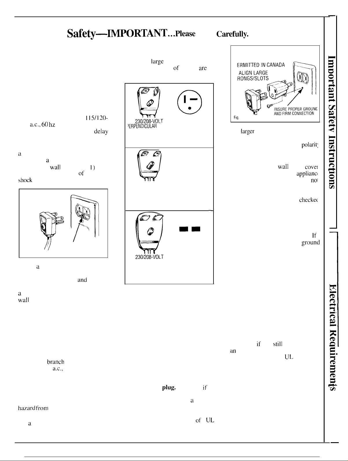
The power cord on these models has
a
three-prong (grounding) plug that
mates with
(grounding)
minimize the possibility
shock
hazard from these appliances.
PREFERRED ,
METHOD
Fig. 1
Where a standard two-prong wall
outlet is encountered, it is your
personal responsibility
obligation to have it replaced with
a
properly grounded three-prong
wall
outlet.
DO NOT. UNDER ANY
CIRCUMSTANCES, CUT OR
REMOVE THE THIRD
(GROUND) PRONG FROM
THE POWER CORD.
230/208-volt models require their
own single branch circuit supplying
230/208-volt
time delay fuse or circuit breaker.
This is recommended for best
performance and to prevent
overloading house wiring circuits,
which
could cause
hazard from
The power cord on these models
has a 230/208-volt perpendicular,
tandem or large tandem type plug
grounded outlet
a
standard three-prong
wall
outlet (Fig. 1) to
+’--
‘%
p
/q
a.c.,
protected with a
a possible fire
overheating wires.
115/120-
delay
of electric
9’
Y,
~
INSURE PROPER
GROUND EXISTS
BEFORE USE
and
that mates respectively with a
230/208-volt perpendicular,
tandem or
outlet. These types
available at most hardware stores.
large
tandem type wall
of outlets
are
@,@
‘Q
*UT
‘ERPENDICUWR
LINE CORD PLUG
REQUIRES 20 AMP TIME DELAY FUSE
OR CIRCUIT BREAKER PROTECTION
-&E
TYPE WALL OUTLET
@
Q
230/208-VOLT
TANDEM TYPE
LINE CORD PLUG
REQUIRES 15 AMP TIME DELAY FUSE
OR CIRCUIT BREAKER PROTECTION
1-
●
MATCHING
0
--
●
o
MATCHING
WALL OUTLET
—
mm
●
o
MATCHING
LARGE TANDEM TYPE
LINE CORD PLUG
REQUIRES 30 AMP TIME DELAY FUSE
OR CIRCUIT BREAKER PROTECTION
Whether your air conditioner is
a 115-volt or a 230/208-volt unit.
it is important to have the wall
outlet and circuit checked by a
qualified electrician if there is
any doubt as to whether a
proper ground exists.
Use of adapter plug
(115-volt models only)
Because of potential safety hazards
under certain conditions, we
strongly recommend against use
of an adapter
you still elect to use an adapter,
where local codes permit,
TEMPORARY CONNECTION
may be made to a properly grounded
two-prong wall outlet by use
listed adapter (Fig. 2) available at
most local hardware stores.
WALL OUTLET
plug.
However,
if
a
of
a
UL
TEMPORARY METHOD
(ADAPTER PLUGS NOT
P
P
Fi~.
2
The
larger
slot in the adapter must
be aligned with the larger slot in the
wall outlet to provide proper
in the connection of the power cord.
CAUTION: Attaching the adapter
ground terminal to
screw does not ground the
unless cover screw is metal, and
insulated, and wall outlet is
grounded through house wiring.
You should have the circuit
by a qualified electrician to make
sure the outlet is properly grounded
When disconnecting the power
cord from the adapter, always
hold the adapter with one hand.
this is not done, the adapter
terminal is very likely to break
with repeated use.
Should the adapter ground
terminal break, DO NOT USE
the appliance until a proper
ground has again been
established.
BEFORE USE
wall
outlet
appliancl
polarit:
covel
nol
checke(
If
ground
Use of extension cords
Because of potential safety
hazards under certain conditions,
we strongly recommend against
the use of an extension cord.
However,
an
extension cord, it is absolutely
necessary that it be a
3-wire grounding type appliance
extension cord and that the current
carrying rating of the cord in
amperes be equal to or greater
than the branch circuit size
shown on the rating nameplate
of the appliance.
if
you
still
elect to use
UL
listed
3
Page 4
Operating Your Air Conditioner Controls
HI
FAN
LO FAN
OFF ■
■
+
—
e
SELECTOR
LO COOL
+
\
■ HI COOL
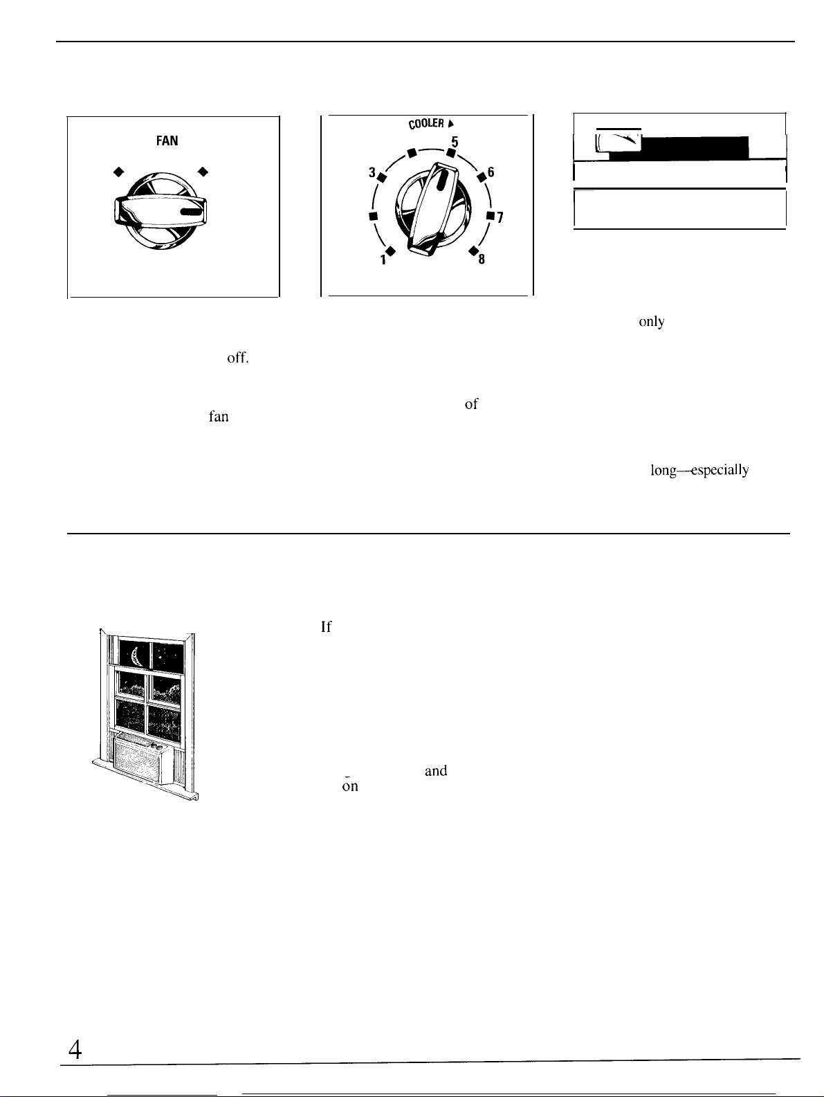
Selector Switch
OFF turns air conditioner
LO FAN provides low fan speed
operation without cooling.
HI FAN provides high
operation without cooling.
LO COOL provides cooling with
low fan speed operation.
HI COOL provides cooling with
high fan speed operation.
fan
off.
speed
COOLER >
4
2
THERMOSTAT
5
7
Thermostat Control
When you move the Thermostat
Control to the desired setting, the
thermostat will automatically
control the temperature of the
indoor air. The higher the number
selected, the cooler the indoor air
will become.
-—
1
I
CLOSE VENT OPEN
—
(ON THE GRILLE FRAME
ABOVE THE CONTROL PANEL)
Ventilation Control
When you move the Ventilation
Control to CLOSE, the vent door is
closed and
room will be circulated and
conditioned. Moving the control to
OPEN opens the vent door,
allowing a small amount of indoor
air to be exhausted from the room.
However, cooling effectiveness is
reduced when this control is set at
OPEN, so we suggest you don’t
keep it there
hot. humid weather.
only
the air inside the
long+specially
in
I
Freezing up
h
Outside air
temperature
dropping
If
you notice that your air
conditioner is not-cooling as it
should, it may be that ice has
formed on the cooling coils. The
ice blocks air flow an-d stops the
unit from cooling the room. This
“freezing up” is a temporary
condition that most often occurs at
night when the Thermostat is set at
a higher number
set
~n
LO COOL.
To correct the condition, set the
and
the Selector is
Selector at HI FAN or HI COOL
and move the Thermostat to the
warmest setting.
Page 5
For normal cooling
For quieter operation
To adjust air direction
1. Set the Selector Switch at HI
COOL.
2. Set the Thermostat Control at
the desired number (usually 4-6 is
a
good starting position). If room
temperature is not satisfactory
after a reasonable time, set the
Thermostat Control at a higher
number
lower number for a warmer room.
3. Set the Ventilation Control at
CLOSE except
when you want to exhaust room air
to the outside.
for
a cooler room or at a
for
brief periods
For maximum cooling
1. Set the Selector Switch at
HI COOL.
2. Turn the Thermostat Control
to 8.
3. Set the Ventilation Control at
CLOSE.
1. Set the Selector Switch at the
LO COOL position.
2. Turn the Thermostat Control to
the desired number.
3. Set the Ventilation Control at
CLOSE.
For nighttime operation
During the cooler evening hours,
we recommend that you set the
Selector Switch
for quieter operation and the
Thermostat Control at mid-range
(4 or 5). Set the Ventilation Control
at CLOSE.
at
LO COOL
For extreme temperatures
For greatest economy and best
performance, we suggest you set
the Selector Switch at HI COOL in
extremely hot weather.
Up and down
The up-and-down air direction
louvers are controlled by tabs
let you position the louvers to
discharge the air up, down or
straight out.
Side to Side
I
I
For
fixed
direction, set the
to ON until the desired air directio
is obtained, then move it to OFF.
For continuous side-to-side air
circulation,
Switch to ON
CIRCULAIRE
OFF
1111111/
m
side-to-side air
Circulaire Switc’
set the Circulaire
and
leave it there.
thal
ON
A
.
Page 6

Care and Cleating
USER MAINTENANCE
INSTRUCTIONS
Turn air conditioner off and
remove the
outlet before cleaning.
Grille & Cabinet
Wipe
lightly dampened with mild liquid
dishwashing detergent. Wash
cabinet with mild
and
lukewarm water.
Outdoor Coil
This coil on the outdoor side
of
the unit should be checked
periodically
clogged with dirt or soot
the atmosphere. If extremely
soiled, it
cleaned, a service available
through your GE service outlet.
Front Grille
Remove the front grille if you need
to
read the
numbers.
To remove the grille:
1. Remove air filter from the grille
by sliding it to the right.
2.
Remove
holds the grille to the chassis.
3. Press inward on the lower right
side of the cabinet until the tab is
clear of the slot and allow the
grille
to come toward you slightly.
4. Repeat this process
left
side.
plug from the wall
front
grille with a clean
soap
or detergent
and
cleaned
may
need to be
mode]
and serial
and save the screw that
for
cloth
if
from
steam
the lower
not pull the bottom edge
Do
toward you more than 3 inches or
damage to the top 2 tabs of the
grille may occur.
5. Grasp the grille’s lower right
and left corner and carefully
straight upward to disengage the
2 top tabs from their slots in
cabinet front edge.
“~
SCREW
To attach the grille:
The grille is attached on the front
the cabinet by
1. Remove air
by sliding it to the right.
2.
Engage
top inside edge with
the cabinet front edge.
3. Press inward on the lower right
side of the metal cabinet at the
location
carefully push the
tab
engages with the slot.
Do not strike or forcibly hit the
plastic
tabs will occur.
4. Repeat this process
left
side.
5. Mount the grille on the t.rent
the cabinet with the screw attached
to the grille during shipping, and
slide the filter back into place.
four
tabs
filter
from the
two tabs on the grille’s
two
of
the slots
grille
or damage to the
and
grille
lift
the
and
a screw.
grille
slots in
then
in until the
for
the lower
of
of
Air Filter
The air
should be washed at least every
days or as often as it needs cleaning
I
To remove the filter,
on the
Vacuum the filter on the dusty side
to remove
filter, cleaner side up, under
tlowing
accumulated dust and lint.
filter
household detergent in the wash
water. Let the filter dry thoroughly
before
When replacing the filter,
the word FRONT is
you slide the filter back into place.
tilter
behind the inlet
grasp the tab
filter
and pull to the right.
light
dust.
Wash
the
water to wash out
If
is very dirty, use a mild
replacing it.
facing
you as
grille
30
gently
the
be sure
6
—
Page 7

Ener~-Saving
Tips
—~—
Questions
● Keep the
●
For
most efficient cooling,
air filter clean.
keep the Ventilation Control in
the CLOSE position except when
you want
to
exhaust air, smoke or
odors from the room.
● Don’ t let the room
get
too
hot. Whenever possible, turn the
unit on before the room heats up.
When heat is “stored up” in walls,
furniture, rugs
and
draperies, your
air conditioner takes longer to
produce the desired comfort
condition.
● Keep windows and doors
closed. Cool, dry air escapes
when they’ re open.
● Keep furnace
cold air returns closed. Cold
floor
registers
and
air
can easily escape through them.
●
Don’t let drapes or furniture block
the top or front
air
flow
when it is operating.
●
It’s best to operate your air
of
unit
and
restrict
conditioner at high speed during
extremely hot weather.
●
Keep the outdoor condenser
coil clean.
●
Turn
air
conditioner
ofi.
before
vacations or extended absences
from
home.
~’
~
~
Use This Problem Solver
PROBLEM
AIR CONDITIONER
DOES NOT OPERATE
AIR CONDITIONER
“DOES NOT COOL
AS IT SHOULD”
OPERATING SOUNDS
POSSIBLE CAUSE
● Not plugged in. Plug may have been bumped
loose by vacuum cleaner or furniture.
● If plugged in, fuse could have blown or
circuit breaker may have tripped.
●
Curtain, blinds or furniture blocking the top or
the front of the air conditioner will restrict air flow.
●
Thermostat Control may not be set high enough.
Move the knob to a higher number. Highest
setting should provide maximum cooling.
● Air filter dirty, should be cleaned at least
every
30
days.
●
Room may have been very hot when air
conditioner was first turned on. Allow time
for it to cool down.
●
Cold air may be escaping through open
furnace floor registers and cold air returns.
● Ventilation Control may be set at OPEN
position, allowing hot outside air to enter
the room.
● Cooling coils have iced up. To melt ice, move
the Selector Switch to
HI
FAN and the
Thermostat Control to a lower number.
● Thermostat click, a metallic sound, may be
heard when compressor cycles on and off. This
is normal.
● Fan runs continuously when Selector
Switch is in COOL or FAN position.
This is normal.
WATER DRIPPING
OUTSIDE
WATER DRIPPING
INSIDE
WATER IN BASE PAN
(ON OUTDOOR SIDE)
● Excess water may overflow in extremely hot
and humid weather. This is normal.
●
Air conditioner must be installed level or
slightly to the outside for proper water disposal.
● This is normal for a short period in areas with
little humidity; normal for a longer period in
very humid areas. Moisture removed from
indoor air drains to rear of cabinet where it is
picked up by a
outdoor condenser coil.
If you need more help...call, toll free:
GE Answer Center
q
800.626.2000
consumer information service
fan
and thrown against the
tilted
7
Page 8

I
INSTALLATION INSTRUCTIONS
BEFORE YOU BEGIN
Read these instructions completely and
carefully.
lMPORTANT–Observe
and ordinances.
lNSTALLER–Be
instructions with the consumer.
CONSUMER—Keep these instructions for
future reference.
sure to leave these
all governing codes
ELECTRICAL REQUIREMENTS
FOR PERSONAL SAFETY:
●
THIS APPLIANCE MUST BE PROPERLY
GROUNDED. See grounding instructions.
● DO NOT, UNDER ANY CIRCUMSTANCES,
CUT OR REMOVE THE THIRD GROUNDING
PRONG FROM THE POWER CORD.
● WE RECOMMEND THAT YOU DO NOT USE
AN EXTENSION CORD OR AN ADAPTER
PLUG WITH THIS APPLIANCE.
● DO NOT CHANGE THE PLUG ON THE
POWER CORD OF THIS APPLIANCE.
● FOLLOW NATIONAL ELECTRICAL CODES
OR LOCAL CODES AND ORDINANCES.
WINDOW REQUIREMENTS
● Standard double-hung window with actual
opening width of
● Clear vertical opening of 1 51\2° minimum from
bottom of sash to stool.
● Install the air conditioner in a window where
there will be enough clearance around the cabinet
to allow ample circulation of air through the unit.
Note:
All
supporting parts should be secured to
firm wood, masonry or metal.
26” to 42”.
115V
15 AMP circuit 20
“parallel” type
II
●
o
● If the electrical supply provided does not meet
the above specifications, call a licensed electrician.
● Aluminum house wiring may pose special
problems–consult a qualified electrician.
● This unit requires a separate circuit serving only
this appliance.
8
230 V/208V 230 V/208V 230 V/208V
AMP circuit 15 AMP circuit
“perpendicular”
type
“tandem” type
30
“tandem”
1-
●
o
AMP circuit
type
Page 9

WINDOW INSTALLATION
TOOLS NEEDED
● Phillips head screwdriver
● Blade-type screwdriver
● Sharp knife or razor blade
● Rule or tape measure
● Pencil
● Level
● Box wrench
SCREWS FURNISHED
Type
Qty-3
A
Type B
Qty-2
(see samples)
Type C
Qly-4
Type D
+
Qty-6
sket
window filler
panel
Sealer (1
Type B
screw
1/2
02.)
L
Type A
screw
+
Right
window fine
panel
(continued next page)
9
Page 10

WINDOW INSTALLATION
❑
❑
REMOVE FRONTGRILLE
See Front Grille section.
~
PREPARE CHASSIS.
1. Remove chassis locking bracket and chassis
locking screw with a Phillips head screwdriver.
(Save for reuse.)
I
b.
1’
Chassis locking screw
\
PREPARE CABINET
1. Install top mounting rail onto top of cabinet
with 3 Type D screws.
(co”t,n”ed)
+
Room side
Top mounting rail
+
r
1~
Chassis locking bracket
2. Remove ground screw and ground wire.
(Save for reuse.)
Ground
w;re
3. Remove chassis from cabinet using the base pan
as a handle.
Type D
screw
2. Install bottom sill channel onto cabinet by
inserting notches on channel into slots located
on bottom of cabinet and securing with 3 Type D
screws.
‘1’ II
10
Page 11

❑
AWACH
1. Slide left window filler panel into top and bottom
mounting rails.
2. Slide retainer panel into window filler panel and
attach to cabinet with 2 Type C screws.
3. Repeat for right side.
wINDowFILLER
PANELs.
5.
Secure top mounting rail with two Type B screws.
Ier
a
Window —
filler panel
o
o
dlF
&
❑
lNS~LL
1. Cut sealing ribbon to window width and stick it
to bottom of the lower window sash.
2. Measure and mark center of window sill to
establish mounting position of cabinet.
3.
Install cabinet into opening and center on line
marked on window sill. Put top of cabinet toward
you and lower window sash behind top mounting
rail.
CABINETIN
Top mounting rail
/
Bottom mounting
Retainer panel
WINDOB
rail
❑
lNS~LL
Cut foam sash gasket to window width and stuff
between top of lower sash and glass panes of
upper sash. Make sure foam gasket is flush with
top of lower sash.
SASH
GASKEZ
– Sealing
ribbon
(ADHESIVE
SIDE)
Center line
4. Extend and secure left and right window filler
panels to window sash with Type A screws, one on
each side.
❑
INSMLL
Install sash locking bracket using Type A screws.
SASH LOCK
Type A
screw
(continued next page)
11
Page 12

WINDOW INSTALLATION
❑
lNS~LL
1.
Slide chassis into cabinet. (Make sure tubing on
unit is not touching wall case.)
2. Lock chassis into cabinet by reinstalling chassis
locking bracket and chassis locking screw removed
in Step 2.
3. Reconnect ground wire removed in Step 2 to
chassis.
4. Remove enough line cord to reach the wall
receptacle.
CHASSIS IN CABINED
Chassis locking bracket
❑
Seal small openings around cabinet with gum-type
sealer, provided.
❑
See Front Grille section.
(Cont,nued)
CHECK FOR AIR LEAKS.
lNSMLL
#RONTGRl[LE
12
Page 13

THROUGH-THE-WALL INSTALLATION
I – –– — — —
THE CABINET MAY BE INSTALLED
THROUGH THE WALL IN BOTH EXISTING
BUILDINGS AND NEW CONSTRUCTION.
❑
PREPARE WALL OPENING.
1.
Determine size of opening. Measure width and
height of cabinet and add 1 /8” to each dimension.
lMPOR~NT
● Any side louvers must project on the
side of the wall.
● The room side of the cabinet must project into
the room at least 1“ from the finished wall.
● The cabinet must be installed level from side to
side and with a 3/8” tilt from front to rear.
oudoor
!
TOOLS REQUIRED
.
Phillips head screwdriver
●
Blade-type screwdriver
●
Magnetic stud finder (optional)
●
Tin snips
✎
Handsaw
✎
Level
●
Chisel
.
Concrete saw (if installing through a masonry wall)
● Hammer
● Caulking gun
● Tape measure
L
ADDITIONAL MATERIALS NEEDED
(obtain locally)
● 12 #10 wood screws, 1“ long
● 1 tube high grade caulking compound
● Wooden framing studs
● Lintel, if required, to support bricks or blocks
above opening
● Flashing, aluminum or galvanized steel
2. Choose the wall opening location. Be sure a
power receptacle is (or will be) installed nearby.
3. Make the opening. Frame it to support the
we;ght
Add metal flashing over bottom of frame opening
and 1“ up on sides to reduce the possibility of
moisture entering the area between the inner and
outer wall. The flashing lip should be 1“ wide and
bent down
❑
Window Installation.
2. With caulking compound or electrical tape,
seal all holes provided in the cabinet for window
installation hardware not used in this installation.
❑
2. Secure cabinet bottom rail to wooden frame
with two 1“ long #10 wood screws.
of the air conditioner.
45:
See the illustration, page 14.
PREPARE THE CABINED
1.
Remove chassis from cabinet. See Step 2 of
lNS~LL
1.
Place cabinet in wall opening.
CABINETIN WALL.
~=~
----
.~,~
,.- . . .
%=-
*\*
~+
q&
+
s.~-
.=
.
\~
?
-\
(continued next page)
13
Page 14

THROUGH-THE-WALL INSTALLATION
❑
INSTALL
3. Secure cabinet sides to wooden frame with six
1“ long # 10 wood screws and secure cabinet top
to frame with four 1“ long #1 O wood screws.
Drill holes in cabinet sides and top, if necessary for
proper installation. If frame is oversize, use shims to
prevent cabinet distortion.
4,
Caulk all four sides on the outdoor side of
cabinet to prevent moisture from getting
through to the interior wall. Use of flashing (a
piece of aluminum or galvanized steel available at
most hardware stores) will further prevent moisture
from getting into interior walls.
5. Install wood trim molding (obtained locally)
around
roomside projection of cabinet, if desired.
CABINETIN WALL
(continued).
——
=
——
~~
~~
Caulking
Flashing Lip
=
Flashing
Flashing
?1
Holes for
#10 1“ Long
Wood
Screws
—-
J
. . .
.
\\
_-__
/
—
. . . .
.—.
—..
:.
\
1
‘1
~
\
;
——-—
,(~
I
i
i-
~in.
<,
/
~:‘,1,,
‘1
(...,,.”,,)
ster
Line
Trim
Molding
(if desired)
INSIDE
~
SllDECHASSISINTO
Lift the chassis and carefully slide it into cabinet. Do
not push on controls or finned coils. Make sure
chassis is firmly seated toward rear of cabinet.
See Step 8 of Window Installation.
❑
/MSMLL
See Care and Cleaning section.
F/LTERAMDGR/lLE
CABINEZ
14
——
Page 15

Wdll
Be There
With the purchase
assurance
from CZE, wdll b;
that if you
there. All you have to do is call–toll-free!
ofyour
ever
new GE appliance, receive the
need information or assistance
GEAnswer Center@
800.626.2000
In-Home Repair
Serv;ce
80MEXARES
(80M32-2737)
A
(;E
(onsumer
will provide exJJcrt
schc~cluled ;tt ii
for you.
(:onlp;itly-opc:r;itecl” loc2itions” off’eiyolI
yotir c(mvenience
Week(i:iys, !):()() Li.111.
rlays).
know
s()
one
M;iny
service
OLli
yoLIr
most rep:iirs
visit.
servi(’c profession:ll”
t-cpilir scIwice,
time
tlla(
convenient
(;E
[;onsuincr
today
01- t.(~tnot-r(~w, (jr iit
(7:()()
to
l’iic:to~-triiirlecl techrrici;ins
iippli;ince inside
c;in
he hiindlecl
a.m.
2:()()
Sen’ice
10
7:()()
p.m.
iincl out-
p.m.
s2l1ul’-
irl,jiIs[
Service Contracts
80@626-2224
W’}]ii(evciyoilt
tll:ilol:i[)pli:irlce,
.
infk)rmiition
h(’lp.
Yolir
will
he
:inswc’red
colirtc’olisly.”
(itnc’. (;F,
open 24
Telecommunicati(
qilestion :ihoilt :in)(;k:
.
Answer
l]ol]t-s 21 (I;iy,
(;E; Allsw,t’t(:erltct-”
scllice
is
(’2ill–>iIld youl” (lLles(i(m-
promptly
And
~’OLl C:itl
(;etltel-”
7
Detice for the Deaf
;iv:iiliil)lc’
:in(~
C2L11
;iny
ser~ice is
(l:iys ii
week.
to
1
Parts
andAccessories
80@626-2002
Individuds quarified to service their
own appliances
pzirts or :iccessf)ries
their home, fic:e ofsllipping ch;~rge!
‘Ihe
(;l~ p~irts system
10
over
47,()()() p;it-ts..
(;cnuine
w:irrimted. VISA, MasIcr(
[Jiscovet ciirds
contained in this
dures intended to be performed
any user. Other Servi;ing
shodd
vice personnel. Caution must be
exercised, since improper servicing
may cause unsafe operation.
Renewal
User maintenance instructions
be referred to quatified ser-
[iin
h:ive
needed
sent directly to
piovidcs
.;ind all
Piirts iit-e fi~lly
2il-e iicc:eptcd.
booktet cover proce-
iic:cess
(;E1
liird
;ind
generfly
by
.“., ,.. .!,,.
. . . . . . .
kr
Customers With
. . . . . . . . .
.,.”.,.
,.,7””5.” ...,.
. . . . . . . . . . . . . . . . . . .
Special Needs...
80f16262000
)
...’,
<.!
I
)
.
Page 16

YOUR GE ROOM AIR CONDITIONER
WARRANTY
Save proof of original purchase date such as your sales slip or
cancelled
check to establish warranty period.
WHAT IS COVERED
WHAT IS NOT COVERED
● Service trips to your home to
teach you how to use the product.
Read your Use and Care material.
If you then have any questions
about operating the product please
contact
Consumer Affairs office at the
address below, or call, toll free:
GE Answer
800.626.2000
consumer information service
your dealer or our
Center@
FULL ONE-YEAR WARRANTY
For one year from date of original
purchase, we
charge,
will provide, free of
pafls and service labor in
your home to repair or replace
any part of the room air
conditioner
of a manufacturing defect.
FULL-FIVE YEAR WARRANTY
For five years from the date of
original purchase, we will provide,
free of charge, parts and service
labor in your home to repair or
replace
that fails because
any
pafl
of
the
sealed
refrigerating system (the
compressor, condenser,
evaporator and all connecting
tubing) that fails because of a
manufacturing defect.
For each of the above warranties:
Transportation
sewice shop and shop service
a
expense to and from
labor if required will be free of
charge.
● Improper installation.
If you have an installation
problem, or if the air conditioner is
of improper cooling capacity for the
intended use, contact your dealer
or installer. You are responsible for
providing adequate electrical
connecting facilities.
● Replacement of house fuses or
resetting of circuit breakers.
●
I
n commercial locations labor
necessary to move the unit to a
location where it is accessible for
service by an individual technician.
This warranty is extended to
the original purchaser and any
succeeding owner for products
purchased for use in the 48
mainland states, Hawaii and
Washington,
warranty is the same except that it
is LIMITED because you must pay
to ship the product to the service
shop or for the service technician’s
travel costs to your home.
All warranty service will be
provided by our Factory Service
Centers or by our authorized
Customer
D.C. In Alaska the
Care@
servicers during
normal working hours.
Look in the White or Yellow Pages
of your telephone directory for
GENERAL ELECTRIC
COMPANY, GENERAL
ELECTRIC FACTORY SERVICE,
GENERAL
FACTORY SERVICE or GENERAL
ELECTRIC CUSTOMER CARE
●
Failure of the product resulting
ELECTRIC-HOTPOINT
@)
from modifications to the product or ‘
due to unreasonable use including
failure to provide reasonable and
necessa~
● Failure due to corrosion on
maintenance.
models not corrosion-protected.
● Damage to product caused
by improper power supply voltage,
accident, fire, floods or acts of God.
WARRANTOR IS NOT
RESPONSIBLE FOR
CONSEQUENTIAL DAMAGES.
I
1
Pub
11-91
Some states do not allow the exclusion or limitation of incidental or consequential damages, so the above limitation or exclusion
may not apply to you. This warranty gives you specific legal rights, and you may also have other rights which
To know what your legal rights are in your state, consult your local or state consumer affairs office or your state’s Attorney General.
Warrantor: General Electric Company
If further help is needed concerning this warranty, write:
Manager—Consumer Affairs, GE Appliances, Louisville, KY 40225
No.
49-7263
CG
I
1
vay
from state to state
A
LA\ll
,
,,”, “ , .
 Loading...