

Page 1
Amersham
™
Typhoon
Operating Instructions
Original instructions
Page 2

Table of Contents
Table of Contents
41 Introduction ..........................................................................................................
51.1 About this manual ................................................................................................................................
61.2 Important user information .............................................................................................................
81.3 Regulatory information ......................................................................................................................
91.3.1 EU Directives ....................................................................................................................................
101.3.2 Eurasian Customs Union ............................................................................................................
111.3.3 Regulations for USA and Canada ...........................................................................................
121.3.4 Korean regulatory information ................................................................................................
131.3.5 Other regulations and standards ............................................................................................
151.4 Abbreviations ..........................................................................................................................................
162 Safety instructions ...............................................................................................
172.1 Radiation ...................................................................................................................................................
192.2 Safety precautions ...............................................................................................................................
272.3 Labels .........................................................................................................................................................
332.4 Emergency procedures ......................................................................................................................
362.5 Recycling information .........................................................................................................................
372.6 Declaration of Hazardous Substances (DoHS) ........................................................................
393 System description ..............................................................................................
403.1 System overview ...................................................................................................................................
433.2 Illustrations ..............................................................................................................................................
473.3 Stages ........................................................................................................................................................
483.3.1 Overview of stages ........................................................................................................................
493.3.2 Fluor stage with accessories .....................................................................................................
533.3.3 Phosphor stage with accessories ...........................................................................................
553.3.4 Multi stage with accessories .....................................................................................................
573.4 Filters ..........................................................................................................................................................
584 Amersham Typhoon Control Software .............................................................
594.1 Main window ...........................................................................................................................................
664.2 Scanning modes ...................................................................................................................................
694.3 General settings ....................................................................................................................................
724.4 Scan area functions .............................................................................................................................
764.5 Image file settings ................................................................................................................................
784.6 View Image mode .................................................................................................................................
815 Installation ............................................................................................................
825.1 Site requirements ..................................................................................................................................
855.2 Delivery and transport .......................................................................................................................
865.3 Setup ...........................................................................................................................................................
885.4 Connections ............................................................................................................................................
2 Amersham Typhoon Operating Instructions 29193226 AC
Page 3

Table of Contents
916 Operation ..............................................................................................................
936.1 Preparing the Amersham Typhoon scanner ............................................................................
946.1.1 Starting the system .......................................................................................................................
976.1.2 Changing the filters .......................................................................................................................
1016.1.3 Custom filters ...................................................................................................................................
1036.2 Preparing the sample .........................................................................................................................
1046.2.1 Preparing a sample for fluorescence imaging ..................................................................
1096.2.2 Preparing a sample for phosphor imaging ........................................................................
1166.2.3 Preparing a sample for densitometry ...................................................................................
1176.3 Performing a scan ................................................................................................................................
1226.4 Procedures after a scan ....................................................................................................................
1247 Maintenance .........................................................................................................
1278 Troubleshooting ...................................................................................................
1288.1 General errors and warnings ..........................................................................................................
1298.2 Error messages ......................................................................................................................................
1319 Reference information ........................................................................................
1329.1 Specifications .........................................................................................................................................
1359.2 Software ....................................................................................................................................................
1369.3 Ordering information ..........................................................................................................................
1389.4 Health and Safety Declaration Forms .........................................................................................
140Index .......................................................................................................................
Amersham Typhoon Operating Instructions 29193226 AC 3
Page 4

1 Introduction
1 Introduction
About this chapter
This chaptercontains importantuser information,descriptions ofsafety notices,regulatory information, and intended use of the Amersham Typhoon system.
In this chapter
This chapter contains the following sections:
See pageSection
51.1 About this manual
61.2 Important user information
81.3 Regulatory information
151.4 Abbreviations
4 Amersham Typhoon Operating Instructions 29193226 AC
Page 5
1.1 About this manual
Purpose of this manual
The Operating Instructions provide you with the information needed to install, operate
and maintain the product in a safe way.
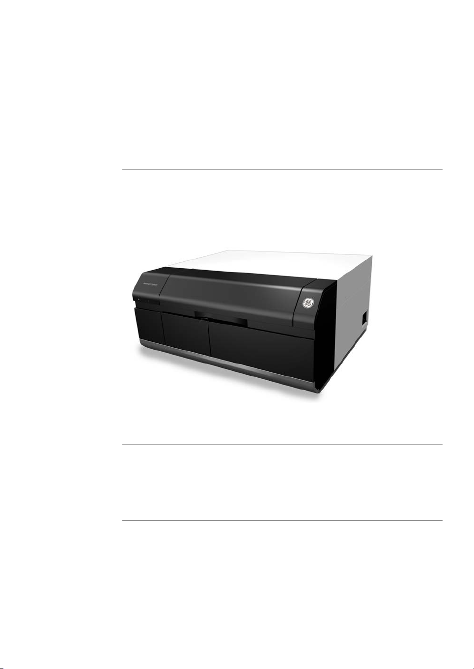
Scope of this manual
The Operating Instructions cover all configurations of Amersham Typhoon scanner and
the Amersham Typhoon Control Software. The illustration below shows the
Amersham Typhoon scanner.
1 Introduction
1.1 About this manual
Descriptions of Amersham Eraser and Amersham Cabinet are not covered in this document.
Typographical conventions
Software items are identified in the text by bold italic text.
Hardware items are identified in the text by bold text (for example, Power switch).
Amersham Typhoon Operating Instructions 29193226 AC 5
Page 6

1 Introduction
1.2 Important user information
1.2 Important user information
Read this before operating the
product
All users must read the entire Operating Instructions before installing, operating or
maintaining the product.
Always keep the Operating Instructions at hand when operating the product.
Do not operate the product in any other way than described in the user documentation.
If you do, you may be exposed to hazards that can lead to personal injury and you may
cause damage to the equipment.
Intended use of the
Amersham Typhoon scanner
The Amersham Typhoon scanner is a versatile laser scanner that can be used for many
different imaging applications, including:
•
imaging of storage phosphor screens
•
fluorescence imaging with multiple lasers, for example for muliplex Western blotting
and two-dimensional difference gel electrophoresis (2D DIGE)
•
imaging of gels with colorimetric stains
•
densitometric imaging, for example of Coomassie™ blue stained gels
Amersham Typhoon scanner is intended for research use only, and shall not be used in
any clinical procedures or for diagnostic purposes.
Prerequisites
In order to operate Amersham Typhoon scanner in the way it is intended, the following
prerequisites must be fulfilled:
•
You must have read and understood the safety instructions in the user documentation.
•
All operations should be performed by qualified personnel who are adequately
trained.
6 Amersham Typhoon Operating Instructions 29193226 AC
Page 7
Safety notices
1 Introduction
1.2 Important user information
•
Amersham Typhoon scanner must be installed in accordance with the site requirements and instructions in Chapter 5 Installation, on page 81.
This user documentation contains safety notices (WARNING, CAUTION, and NOTICE)
concerning the safe use of the product. See definitions below.
WARNING
WARNING indicates a hazardous situation which, if not avoided,
could resultin deathor serious injury. It is important notto proceed
until all stated conditions are met and clearly understood.
CAUTION
CAUTION indicates a hazardous situation which, if not avoided,
could result in minor or moderate injury. It is important not to proceed until all stated conditions are met and clearly understood.
NOTICE
NOTICE indicates instructions that must be followed to avoid
damage to the product or other equipment.
Notes and tips
Note:
Tip:
Amersham Typhoon Operating Instructions 29193226 AC 7
A note is used to indicate information that is important for trouble-free and
optimal use of the product .
A tip contains useful information that can improve or optimize your procedures.
Page 8

1 Introduction
1.3 Regulatory information
1.3 Regulatory information
Introduction
This sectionlists theregulations and standards that applyto Amersham Typhoon scanner.
Manufacturing information
The table below summarizes the required manufacturing information.
In this section
InformationRequirement
GE Healthcare Bio-Sciences AB,Name and address of manufacturer
Björkgatan 30, SE 751 84 Uppsala, Sweden
See pageSection
91.3.1 EU Directives
101.3.2 Eurasian Customs Union
111.3.3 Regulations for USA and Canada
121.3.4 Korean regulatory information
131.3.5 Other regulations and standards
8 Amersham Typhoon Operating Instructions 29193226 AC
Page 9
1.3.1 EU Directives
Conformity with EU Directives
This product fulfills the European Directives listed below. See the EU Declaration of
Conformity for the directives and regulations that apply for the CE marking.
If not included with the product, a copy of the EU Declaration of Conformity is available
on request.
CE marking
1 Introduction
1.3 Regulatory information
1.3.1 EU Directives
TitleDirective
Machinery Directive (MD)2006/42/EC
Electromagnetic Compatibility (EMC) Directive2014/30/EU
Low Voltage Directive (LVD)2014/35/EU
Restriction of Hazardous Substances (RoHS) Directive2011/65/EU
The CE marking and the corresponding EU Declaration of Conformity is valid for the instrument when it is:
•
used according to the Operating Instructions or user manuals, and
•
used in the same state as it was delivered from GE, except for alterations described
in the Operating Instructions or user manuals.
Amersham Typhoon Operating Instructions 29193226 AC 9
Page 10

1 Introduction
1.3 Regulatory information
1.3.2 Eurasian Customs Union
1.3.2 Eurasian Customs Union
Introduction
This section contains additional regulatory information to comply with the Eurasian
Customs Union technical regulations.
Manufacturer and importer
information
The table below summarizes the manufacturer and importer information required by
the Eurasian Customs Union.
ing information about importer
InformationRequirement
See Manufacturing informationName and address of manufacturer
Telephone: + 46 771 400 600Telephone number of manufacturer
GE Healthcare LLCImporter and/orcompany forobtain-
GE Healthcare Life Sciences
Presnenskaya nab., 10C, 12th floor
RU-123 317 Moscow, Russian Federation
Telephone 1: + 7 495 411 9714
Fax nr: + 7 495 739 6932
Email: LSrus@ge.com
10 Amersham Typhoon Operating Instructions 29193226 AC
Page 11

1.3.3 Regulations for USA and Canada
NRTL certification
This symbol indicates that Amersham Typhoon has been certified by a Nationally Recognized Testing Laboratory (NRTL).
NRTL means an organization, which is recognized by the US Occupational Safety and
Health Administration (OSHA) as meeting the legal requirements of Title 29 of the Code
of Federal Regulations (29 CFR), Part 1910.7.
FCC compliance
This device complies with part 15 of the FCC Rules. Operation is subject to the following
two conditions: (1) This device may not cause harmful interference, and (2) this device
must acceptany interference received, includinginterference that maycause undesired
operation.
Note:
This equipment has been tested and found to comply with the limits for a Class A digital
device, pursuant to part 15 of the FCC Rules. These limits are designed to provide reasonable protection against harmful interference when the equipment is operated in a
commercial environment. This equipment generates, uses,and canradiate radiofrequency energy and, if not installed and used in accordance with the instruction manual, may
cause harmful interference to radio communications. Operation of this equipment in a
residential area is likely to cause harmful interference in which case the user will be required to correct the interference at his own expense.
The user is cautioned that any changes or modifications not expressly approved
by GE could void the user’s authority to operate the equipment.
1 Introduction
1.3 Regulatory information
1.3.3 Regulations for USA and Canada
Amersham Typhoon Operating Instructions 29193226 AC 11
Page 12
1 Introduction
1.3 Regulatory information
1.3.4 Korean regulatory information
1.3.4 Korean regulatory information
NOTICE
Class A equipment (equipment for business use).
This equipment has been evaluated for its suitability for use in a
business environment.
When usedin a residential environment, there is a concern of radio
interference.
주의사항
A급 기기 (업무용 방송통신 기자재)
이 기기는 업무용환경에서 사용할 목적으로 적합성평가를 받은
기기
로서 가정용 환경에서 사용하는 경우 전파간섭의 우려가 있습니
다.
12 Amersham Typhoon Operating Instructions 29193226 AC
Page 13

1.3.5 Other regulations and standards
Environmental conformity
This product conforms to the following environmental requirements.
TitleRequirement
Waste Electrical and Electronic Equipment (WEEE) Directive2012/19/EU
1 Introduction
1.3 Regulatory information
1.3.5 Other regulations and standards
China RoHS
Standards, machinery and
electrical equipment
Harmonized standard requirements fulfilledby this product aresummarized in the table
below.
EN 61010-1, IEC 61010-1,
UL 61010-1, CAN/CSAC22.2 No. 61010-1
IEC/EN 61010-2-081,
UL61010-2-081, CAN/CSAC22.2 No. 61010-2-081
EN 61326-1, IEC 61326-1,
FCC Part 15 B Class A,
ICES-003 Class A
Management Methods for the Restriction of the Use of Hazardous Substances in Electrical and Electronic Products.
DescriptionStandard
Safety requirements for electrical equipment for measurement, control, and laboratory use - Part 1: General
requirements.
Particular requirements for automatic and semi-automatic laboratory equipment for analysis and other
purposes.
Electrical equipment for measurement, control and
laboratory use - EMC requirements.
NOTICE
This equipmentis notintended for
use in residential environments
and may not provide adequate
protection to radio reception in
such environments.
EN ISO 12100
Amersham Typhoon Operating Instructions 29193226 AC 13
Safety of machinery. General principles for design. Risk
assessment and risk reduction.
Degrees of protection provided by enclosures.EN60529, IEC60529
Page 14
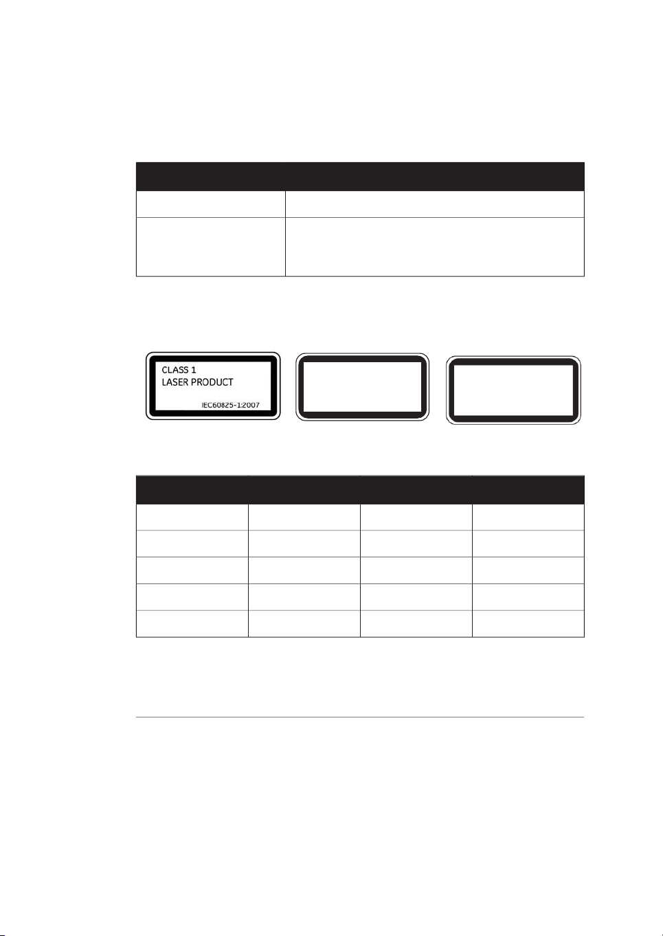
CLASS 1
LASER PRODUCT
EN60825-1 : 2014
CLASS 1
LASER PRODUCT
IEC60825-1:2014
1 Introduction
1.3 Regulatory information
1.3.5 Other regulations and standards
Regulations and standards,
products containing lasers
Subchapter J, Part
1040.10 Laser Products
This instrument is a class 1 Laser Product (IEC60825-1/EN60825-1). This instrument
meets the laser radiation safety requirements specified in the Code of the Federal Regulations (21 CFR, Chapter 1, Subchapter J).
DescriptionRegulation / Standard
Safety of laser productsEN/IEC 60825-1
Safety of laser productsUSA 21 CFR, Chapter I,
The following lasers can be installed in the Amersham Typhoon scanner:
Maximum powerOperating powerWavelengthLaser and class
70 mW25 mW (CW)488 nmLD laser, class 3B
80 mW10 mW (CW)532 nmSHG laser,class 3B
220 mW84 mW (CW)635 nmLD laser, class 3B
290 mW50 mW (CW)685 nmLD laser, class 3B
230 mW100 mW (CW)785 nmLD laser, class 3B
Note:
The beam divergence of all laser modules is collimated.
Different lasers are installed depending on the configuration, see Main components in
Amersham Typhoon scanner, on page 132.
14 Amersham Typhoon Operating Instructions 29193226 AC
Page 15

1.4 Abbreviations
The abbreviations used in this Operating Instructions are defined as follows:
1 Introduction
1.4 Abbreviations
DescriptionAbbreviation
Two-dimensional Difference Gel Electrophoresis2D DIGE
Optical densityOD
Photo-multiplier tubePMT
Red Green BlueRGB
Relative humidityRH
RadioisotopeRI
Second harmonic generation nonlinear optical processSHG
Titer plateTP
Ultraviolet radiationUV
Near-infrared radiationNIR
Amersham Typhoon Operating Instructions 29193226 AC 15
Page 16
2 Safety instructions
2 Safety instructions
About this chapter
This chapter describes safety precautions, labels and symbols that are attached to the
equipment. In addition,the chapterdescribes emergency and recovery procedures, and
provides recycling information.
WARNING
Before installing, operating or maintaining the product, all users
must read and understand the entire contents of this chapter
to become aware of the hazards involved.
In this chapter
See pageSection
172.1 Radiation
192.2 Safety precautions
272.3 Labels
332.4 Emergency procedures
362.5 Recycling information
372.6 Declaration of Hazardous Substances (DoHS)
16 Amersham Typhoon Operating Instructions 29193226 AC
Page 17
2.1 Radiation
Radiation hazard prevention
This instrument is not equipped with any radioisotope or radiation generating unit, and
is therefore not regulated by radiationhazard prevention laws. However, the instrument
is capableof scanningstorage phosphorscreens which may be polluted by radioisotopes.
CAUTION
If radioisotope (RI) pollution occurs, stop use of the instrument immediately andfollow theinstructions of your radiation administrator.
Controlled area
Paragraph 1of Article1 ofthe LawEnforcement Rulesfor Prevention ofRadiation Hazards
due to Radioisotope and so forth (Prime Minister's Office ordinance No. 56) defines the
controlled area as "a place where the dose equivalent related to external radiation exceeds the dose equivalent determined by the Director General of the Science and
Technology Agency (hereinafter referred to as the Director General), the concentration
of radioisotopein theair exceedsthe concentrationdetermined by the Director General,
or the radioisotope density on the surface polluted by radioisotope exceeds the density
determined by the Director General."
2 Safety instructions
2.1 Radiation
Limit of superficial pollution
Paragraph 3 of Article 4 of Notice No. 15 of the Science and Technology Agency that
determines thequantity, etc.of radiatingisotope specifiesthat thedensity of radioisotope
on thesurface polluted by radioisotope must be one tenth of the density defined in Article
8.
Article 8 and Table 3 of this Notice define the limits as shown below:
1
Superficial density of radioisotope that radiates alpha rays: 4 Bq/cm
2
Superficial density of radioisotope that does not radiate alpha rays: 40 Bq/cm
Amersham Typhoon Operating Instructions 29193226 AC 17
2
2
Page 18

2 Safety instructions
2.1 Radiation
Installation site of instrument
This instrument is capable of scanning not only storage phosphor screens but also fluorescent pigment label samples (non-RI method). Therefore, it is recommended that the
user should install it outside the controlled area and use RI-indicated samples without
contacting them with storage phosphor screens directly.
However, as described above, the storage phosphor screen surface may be polluted by
radioisotope (RI), depending on the sample condition, since the instrument sticks the
sample to the3H-compatible storage phosphor screen surface and exposes it in an
auto-radiography experiment of the3H label sample.
The degree of superficial pollution of the storage phosphor screen is greatly influenced
by thedryness of thesample and doseof radioisotopein an experimentand may exceed
the limits mentioned in the section above.
When the instrument reads a storage phosphor screen with a polluted non-exposure
area, it may be polluted. The degree of such superficial pollution greatly differs with
users' operationconditions. Superficialpollution mayexceed thelimit mentionedabove.
Note:
As mentioned above, install this instrument in the RI controlled area if the user
uses RI-indicated samples that will be in direct contact with storage phosphor
screens.
Removal from the controlled
area
If it is necessary to move the instrument and its laboratory, which were installed and
have been used in the controlled area, from the controlled area, make sure that the degree ofthe superficial pollution is below the limits mentioned in Limit of superficial pollu-
tion, on page 17 above.
18 Amersham Typhoon Operating Instructions 29193226 AC
Page 19
2.2 Safety precautions
Introduction
Amersham Typhoon scanner is powered by mains voltage and handles materials that
may be hazardous. Before installing, operating or maintaining the system, you must be
aware of the hazards described in this manual.
Follow the instructions provided to avoid personal injuries, damage to the product ,
or to other personnel and equipment in the area.
The safety precautions in this section are grouped into the following categories:
•
General precautions
•
Personal protection
•
Power supply
•
Installing and moving the system
•
System operation
•
Maintenance
2 Safety instructions
2.2 Safety precautions
General precautions
WARNING
Do notuse theequipment ifsmoke, strangenoises orstrange odors
can be perceived, or if the equipment becomes unusually hot. This
may result in fire or electric shock.
Stop using the equipment immediately, turn off the power switch
and unplug the equipment from the power outlet. Contact your
local GE representative to request repair.
WARNING
Do notdamage thepower supplycord by bending, twisting, heating
or allowing them to become pinned under the equipment. Using
damaged power cords could result in fire or electric shock.
If the power supply cords are damaged, contact your local GE
representative for replacements.
Amersham Typhoon Operating Instructions 29193226 AC 19
Page 20
2 Safety instructions
2.2 Safety precautions
WARNING
Do notallow liquids,flammable materialsor metallicobjects to get
into theAmersham Typhoon.This mayresult infire or electric shock.
In case of malfunction, turn off the power switch, unplug the
equipment from thepower outlet, thencontact you localGE representative.
WARNING
Never detach the inner cover screwed to this instrument. If it is
detached, laser beam may leak with a risk of loss of vision.
WARNING
Never modify the interlocks in this instrument, laser beam may leak
with a risk of loss of vision.
CAUTION
If radioisotope (RI) pollution occurs, stop use of the instrument immediately andfollow theinstructions of your radiation administrator.
CAUTION
Use of controls or adjustments or performance of procedures
other thanthose specifiedherein mayresult in hazardous radiation
exposure.
NOTICE
Avoid anyshock orvibration tothe equipment, asthis maydamage
the equipment.
20 Amersham Typhoon Operating Instructions 29193226 AC
Page 21
Personal protection
Power supply
2 Safety instructions
2.2 Safety precautions
CAUTION
Always wear gloves, protective glasses and a lab coat or similar
when handling samples.
CAUTION
Always wear cotton gloves when handling storage phosphor
screens.
WARNING
Do not use the equipment with a power supply other than that
recommended. Fire and electric shock could result.
WARNING
The Amersham Typhoon scanner must always be connected to a
grounded power outlet.
WARNING
Do not block access to the power switch and power cord. The
power switch must always be easy to access. The power cord with
plug must always be easy to disconnect.
WARNING
Connect thepower supplydirectly to a grounded wallpower outlet.
The useof extension cords ormultiple loads on one electrical outlet
could result in fire and electric shock.
Amersham Typhoon Operating Instructions 29193226 AC 21
Page 22
2 Safety instructions
2.2 Safety precautions
Installing and moving
WARNING
Only use power cords delivered or approved by GE.
CAUTION
Do notuse the samepower supplyas that of large equipmentsuch
as an air conditioner or centrifuge. Malfunction could result.
WARNING
Do not block the ventilation inlets or outlets on the system.
WARNING
Do not place the equipment on unstable tables or on inclined surfaces, asthe equipment couldbe droppedor fall, resultingin injury.
CAUTION
Only authorized service personnel are allowed to install or move
Amersham Typhoon scanner.Contact your localGE representative
for help and advice.
CAUTION
Install the Amersham Typhoon scanner in a location where it will
not come into contact with water or chemicals.
22 Amersham Typhoon Operating Instructions 29193226 AC
Page 23
2 Safety instructions
2.2 Safety precautions
CAUTION
•
Do not connect any USB devices other than the
Amersham Typhoon scanner to the computer in which the
Amersham Typhoon Control Software is installed. Malfunction
could result.
•
Use only the Amersham Typhoon Control Software during
scanning.
CAUTION
Connect the computer hardware on the same power circuit as the
scanner, otherwise the equipment may be influenced by electrical
noise.
CAUTION
Do not block the cooling fans. If they are blocked, the instrument
may malfunction.
NOTICE
Any computer used with the equipment must comply with EN/IEC
60950-1, andbe installedand usedaccording to themanufacturer's
instructions.
Operation
WARNING
Do not use the instrumentwithin or near a sink, or in humid(above
70% RH)or dustyenvironments. Fire andelectric shockcould result.
Amersham Typhoon Operating Instructions 29193226 AC 23
Page 24
2 Safety instructions
2.2 Safety precautions
WARNING
When opening or closing the main scanner door, make sure that
no objects or body parts are caught in the main scanner door.
CAUTION
Do not place heavy objects on the instrument, these may fall off
and cause injury.
CAUTION
Do not open the main scanner door or filter door while the device
is in operation. Injury could result.
CAUTION
Do notscratch or dropparts containingglass suchas lenses, filters
or lights.
CAUTION
Handle the sample stages and the digitization plate with care to
avoid dropping them.
CAUTION
Be careful not to break the glass surface of the fluor stage.
CAUTION
Reagents usedto prepare thesample should be used in accordance
with the manufacturer instructions.
24 Amersham Typhoon Operating Instructions 29193226 AC
Page 25
2 Safety instructions
2.2 Safety precautions
CAUTION
Do notleave samples inthe instrumentafter scanning. Ifleft, these
may degrade and cause damage to the instrument.
CAUTION
Do not insert a storage phosphor screen in Amersham Typhoon
before turning on the machine. If a storage phosphor screen is
detected during the self-diagnosis of the Amersham Typhoon, the
sensitivity of the storage phosphor screen may deteriorate and
reduce the quality of the scanned data.
CAUTION
Do not turn off power during operation as this can cause loss of
data in the internal memory. Only turn off power in an emergency
situation.
CAUTION
Do not use the instrumentwithin or near a sink, or in humid(above
70% RH) or dusty environments. This can result in data failure.
NOTICE
The automatic sleep mode of the computer should be turned off
to prevent the computer from entering sleep mode during a scan.
Otherwise loss of data might occur.
Maintenance
WARNING
Do not attempt to modify the instrument, or fire and electric shock
could result.
Amersham Typhoon Operating Instructions 29193226 AC 25
Page 26
2 Safety instructions
2.2 Safety precautions
WARNING
Do not use excessive amounts of liquids for cleaning the
Amersham Typhoon, this may result in product malfunction or
electric shock.
CAUTION
Wear gloves to prevent direct contact with chemical substances.
CAUTION
Take care when connectingthe power supplycable. Do not tug on
the cable,and do not handle the connection plugs with wethands.
CAUTION
Turn off the power switch and remove connecting cables before
moving the equipment.
CAUTION
Turn the power switch off before cleaning the inside of the equipment.
CAUTION
Unplug the equipment if it will not be used for an extended period.
26 Amersham Typhoon Operating Instructions 29193226 AC
Page 27
2.3 Labels
About this section
This section describes the system label and other safety or regulatory labels that are
attached to Amersham Typhoon scanner.
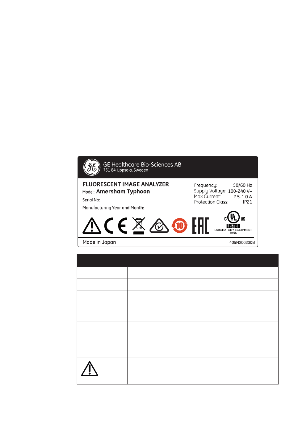
System label
The illustration below shows an example of a system label that is attached to
Amersham Typhoonscanner. The system label identifies the productand showselectrical
data and regulatory compliance.
2 Safety instructions
2.3 Labels
DescriptionLabel text
Instrument modelModel
Instrument serial numberSerial number
Manufacturing year and monthManufacturing
Year and Month
Supply voltage frequencyFrequency
Supply voltageSupply Voltage
Max. current consumptionMax Current
Protection class. Ingress protection according to IEC 60529.Protection class
Warning! Read the user documentation before using the system. Donot openany covers or replaceparts unless specifically
stated in the user documentation.
Amersham Typhoon Operating Instructions 29193226 AC 27
Page 28
2 Safety instructions
2.3 Labels
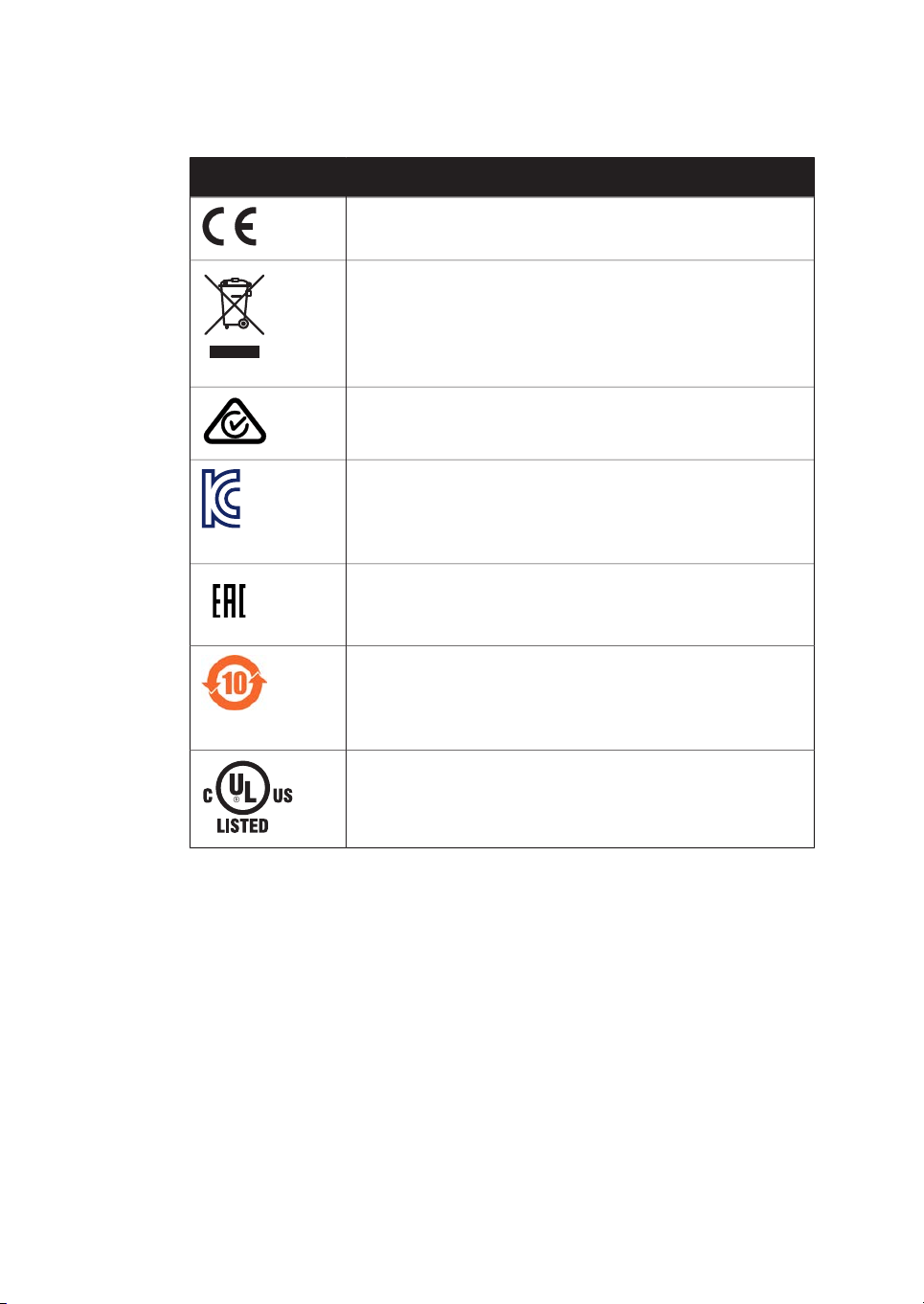
DescriptionLabel text
The system complies with applicable European directives.
This symbol indicates that waste electrical and electronic
equipment must not be disposed as unsorted municipal waste
and mustbe collectedseparately. Pleasecontact anauthorized
representative of the manufacturer forinformation concerning
the decommissioning of equipment.
The systemcomplies withthe requirements for electromagnetic
compliance (EMC) in Australia and New Zealand.
This symbolindicates RRA registration ofcompatibility inKorea.
The registration number of the product will appear beside the
symbol. This equipment has been tested and found to comply
with the limits for a Class A digital device.
Eurasian Conformitymark: thesingle conformitymark indicates
that the product is approved for circulation on the markets of
the member states of the Eurasian Customs Union.
This symbol indicates that the product contains hazardous
materials in excess of the limits established by the Chinese
standard SJ/T11364-2014 Requirements for Concentration
Limits for Certain Hazardous Substances in Electronics.
This symbol indicates that Amersham Typhoon scanner has
been certified by a Nationally Recognized Testing Laboratory
(NRTL).
28 Amersham Typhoon Operating Instructions 29193226 AC
Page 29
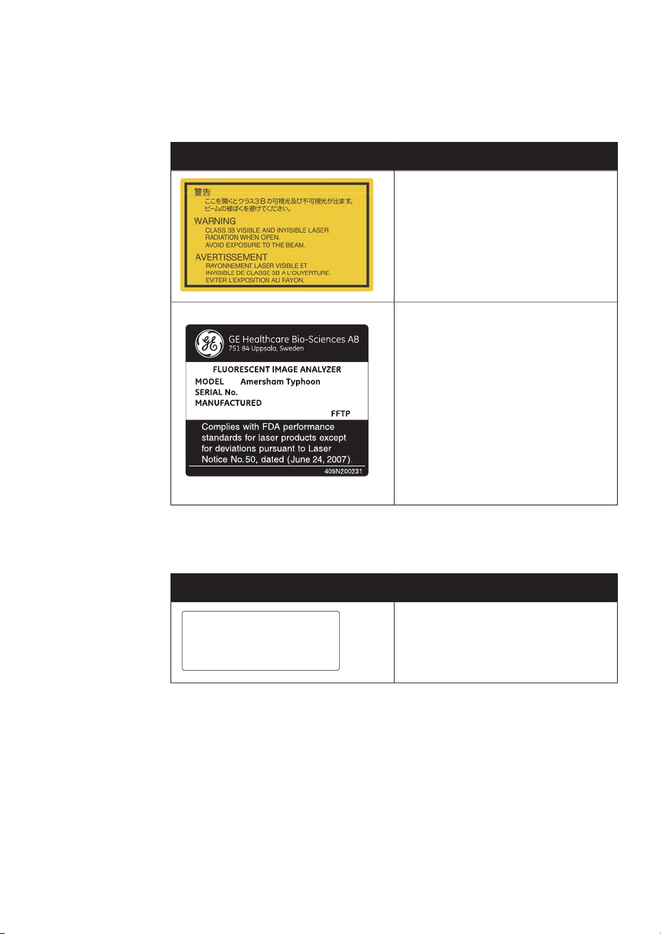
Labels concerning lasers
This device complies with part 15 of the FCC Rules.
Operation is subject to the following two conditions:
(1) This device may not cause harmful interference, and
(2) this device must accept any interference received,
including interference that may cause undersired operation.
CAN ICES-3 (A)/NMB-3(A)
2 Safety instructions
2.3 Labels
MeaningLabel
Warning! The instrument containslasers
and service is only allowed by trained
service engineers. Do not modify the instrument in any way.
This product complies with FDA performance standards for laser products except for deviations pursuant to Laser
Notice No. 50, dated (June 24, 2007).
Other safety labels
Amersham Typhoon Operating Instructions 29193226 AC 29
MeaningLabel
This device complies with part 15 of the
FCC rules.
CAN ICES-3 (A)/NMB-3 (A)
Page 30
2 Safety instructions
2.3 Labels
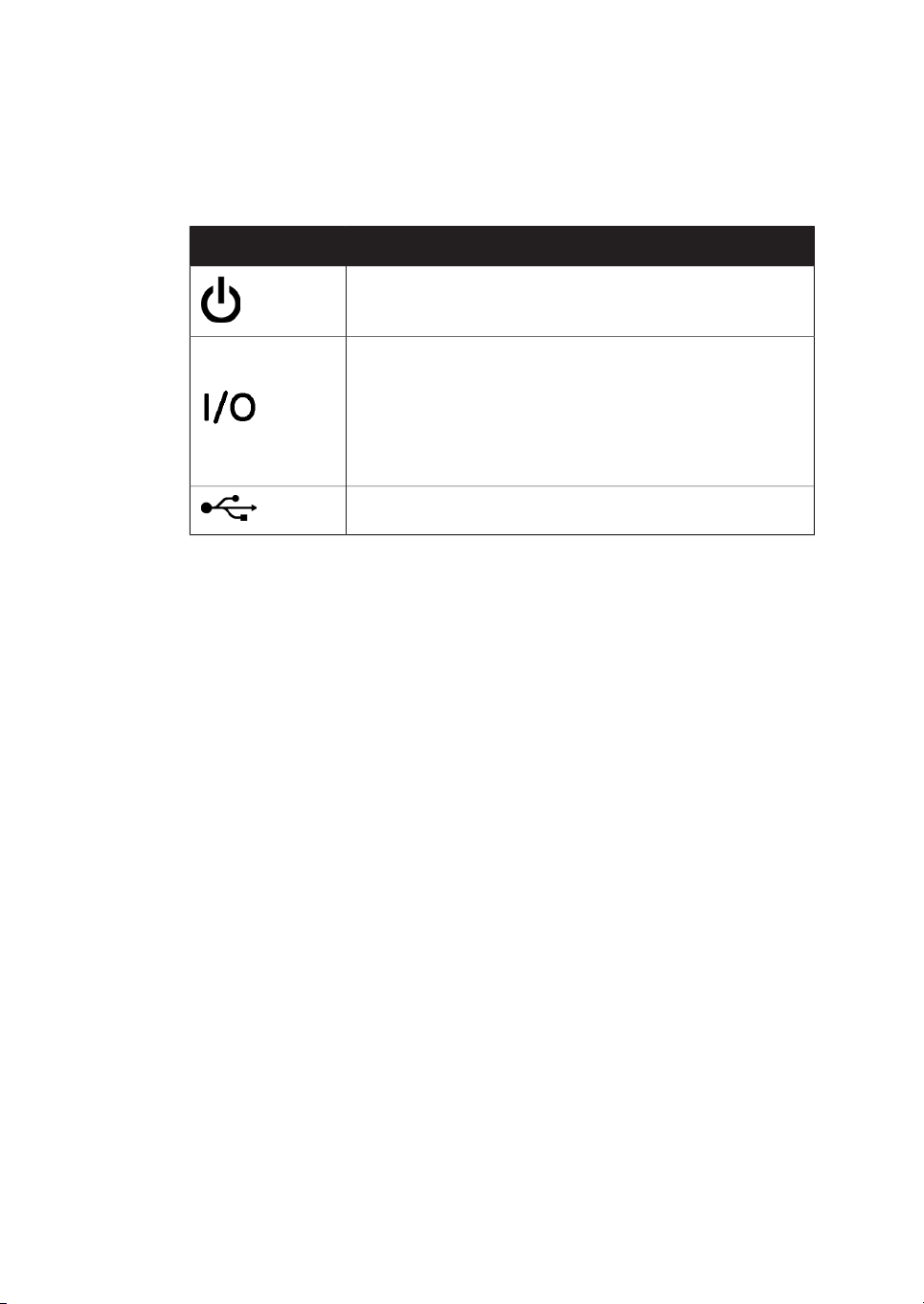
Symbols on the
Amersham Typhoon scanner
MeaningLabel
On/Off switch
Power switch
l: Power ON
O: Power OFF
USB port
30 Amersham Typhoon Operating Instructions 29193226 AC
Page 31

Location of labels and symbols
on the Amersham Typhoon
scanner
2 Safety instructions
2.3 Labels
Amersham Typhoon Operating Instructions 29193226 AC 31
Page 32

2 Safety instructions
2.3 Labels
Interlock parts inside the
Amersham Typhoon scanner
Never insertany foreignobjects into the interlock parts to avoid potential laser exposure
and injury.
32 Amersham Typhoon Operating Instructions 29193226 AC
Page 33

2.4 Emergency procedures
About this section
This sectiondescribes how to do an emergency shutdownof AmershamTyphoonscanner.
The section also describes the results of a power failure.
Precautions
WARNING
Access to power switch and power cord with plug. Do not block
access to the power switch and power cord. The power switch
must always be easy to access. The power cord with plug must
always be easy to disconnect.
2 Safety instructions
2.4 Emergency procedures
Amersham Typhoon Operating Instructions 29193226 AC 33
Page 34

2 Safety instructions
2.4 Emergency procedures
Emergency shutdown
In an emergency situation, follow the steps below to stop the scan:
ActionStep
Click the Stop button in the Amersham Typhoon Control Software.1
2
Turn off the Amersham Typhoon scanner by switching the power switch on
the right side of the instrument to the O position.
Disconnect the power cord from the wall socket.3
34 Amersham Typhoon Operating Instructions 29193226 AC
Page 35

Power failure
2 Safety instructions
2.4 Emergency procedures
The following table describes the consequences of a power failure.
will result in...Power failure to...
Amersham Typhoon
scanner
Computer running the
control software
Amersham Typhoon
scanner and computer
running the control software
Restart after emergency
shutdown or power failure
Follow theinstructions torestart the instrument after an emergency shutdownor power
failure.
ActionStep
1
Make sure that the condition that caused the emergency shutdown or
power failure is corrected.
The scanis interruptedimmediately. Theinstrument
•
is in an undefined state.
The data collected up to the time of the power fail-
•
ure is available in the file created when starting the
scan.
The computer shuts down immediately.
•
The run continues, but no data is saved.
•
The scanis interruptedimmediately. Theinstrument
•
is in an undefined state.
The computer shutsdown immediately andno data
•
is saved.
2
3
Amersham Typhoon Operating Instructions 29193226 AC 35
If powerto theinstrument hasbeen lost, re-start the instrument as described
in Start the Amersham Typhoon scanner, on page 94.
Re-start the computer and Amersham Typhoon Control Software as described in Start the Amersham Typhoon Control Software, on page 95.
Page 36

2 Safety instructions
2.5 Recycling information
2.5 Recycling information
Introduction
This section contains information about the decommisioning of Amersham Typhoon
scanner.
Decontamination
The product must be decontaminated before decommissioning. All local regulations
must be followed with regard to scrapping of the equipment.
General instructions for disposal
When taking Amersham Typhoon scanner out of service, the different materials must
be separated and recycled according to national and local environmental regulations.
Specific instructions for disposal
Measure the superficial radio isotope pollution of the instrument and storage phosphor
screen as mentioned in the Radiation hazard prevention, on page 17.
If the pollution level exceeds the limit, dispose of the instrument as radioactive waste.
Otherwise, dispose of the materials according to applicable laws and regulations for
disposal of industrial waste.
Disposal of electrical
components
Waste ofelectrical andelectronic equipment must not be disposed as unsorted municipal
waste and must be collected separately. Please contact an authorized representative
of themanufacturerfor information concerningthe decommissioning ofthe equipment.
36 Amersham Typhoon Operating Instructions 29193226 AC
Page 37

2 Safety instructions
2.6 Declaration of Hazardous Substances (DoHS)
2.6 Declaration of Hazardous Substances (DoHS)
根据SJ/T11364-2014《电子电气产品有害物质限制使用标识要求》特提供如下有关污染控制方面的
信息。
The following product pollution control information is provided according to SJ/T11364-2014 Marking
for Restriction of Hazardous Substances caused by electrical and electronic products.
电子信息产品污染控制标志说明
Explanation of Pollution Control Label
该标志表明本产品含有超过中国标准GB/T 26572 《电子电气产品中限用物质的限
量要求 》中限量的有害物质。标志中的数字为本产品的环保使用期,表明本产品
在正常使用的条件下,有毒有害物质不会发生外泄或突变,用户使用本产品不会
对环境造成严重污染或对其人身、财产造成严重损害的期限。单位为年。
为保证所申明的环保使用期限,应按产品手册中所规定的环境条件和方法进行正
常使用,并严格遵守产品维修手册中规定的定期维修和保养要求。
产品中的消耗件和某些零部件可能有其单独的环保使用期限标志,并且其环保使
用期限有可能比整个产品本身的环保使用期限短。应到期按产品维修程序更换那
些消耗件和零部件,以保证所申明的整个产品的环保使用期限。
本产品在使用寿命结束时不可作为普通生活垃圾处理,应被单独收集妥善处理。
This symbolindicates theproduct containshazardous materials in excessof thelimits
established by the Chinese standard GB/T 26572 Requirements of concentration
limits for certain restricted substances in electrical and electronic products. The
number in the symbol is the Environment-friendly Use Period (EFUP), which indicates
the period during which the hazardous substances contained in electrical and electronic products will not leak or mutate under normal operating conditionsso that the
use ofsuch electricaland electronicproducts willnot result inany severeenvironmental pollution,any bodily injury or damage to anyassets. Theunit of the period is “Year”.
In order to maintain the declared EFUP, the product shall be operated normally according to the instructions and environmental conditions as defined in the product
manual, and periodic maintenance schedules specified in Product Maintenance Procedures shall be followed strictly.
Consumables or certain parts may have their own label with an EFUP value less than
the product. Periodic replacement of those consumables or parts to maintain the
declared EFUP shall be done in accordancewith theProduct MaintenanceProcedures.
This product must not be disposed of as unsorted municipal waste, and must be
collected separately and handled properly after decommissioning.
Amersham Typhoon Operating Instructions 29193226 AC 37
Page 38

2 Safety instructions
2.6 Declaration of Hazardous Substances (DoHS)
有害物质的名称及含量
Name and Concentration of Hazardous Substances
产品中有害物质的名称及含量
Table of Hazardous Substances’ Name and Concentration
部件名称
Component name
本表格依据SJ/T 11364的规定编制。
This table is prepared according to SJ/T 11364.
0:
X:
•
0:
X:
表示该有害物质在该部件所有均质材料中的含量均在 GB/T 26572规定的限量要求以下。
表示该有害物质至少在该部件的某一均质材料中的含量超出 GB/T 26572规定的限量要
求。
此表所列数据为发布时所能获得的最佳信息。
Indicates that this hazardous substance contained in all of the homogeneous materials for
this part is below the limit requirement in GB/T 26572.
Indicates that this hazardous substance contained in at least one of the homogeneous
materials used for this part is above the limit requirement in GB/T 26572.
有害物质
Hazardous substance
铅
(Pb)
汞
(Hg)
镉
(Cd)
六价铬
(Cr(VI))
多溴联苯
(PBB)
多溴二苯醚
(PBDE)
000X0X29187191
000X0X29187193
00000X29187194
000X0X29238583
•
38 Amersham Typhoon Operating Instructions 29193226 AC
Data listed in the table represents best information available at the time of publication.
Page 39

3 System description
About this chapter
This chapter gives an overview of Amersham Typhoon scanner and a brief description
of its function.
In this chapter
3 System description
See pageSection
403.1 System overview
433.2 Illustrations
473.3 Stages
573.4 Filters
Amersham Typhoon Operating Instructions 29193226 AC 39
Page 40

1
2
3
3 System description
3.1 System overview
3.1 System overview
Introduction
The Amersham Typhoon scanner is a laser scanner that can be used for many different
imaging applications. The scanner is part of the complete Amersham Typhoon system,
that consists of the scanner, an eraser and a cabinet.
For moreinformation on how to safely operate the Amersham Eraser, read theAmersham
Eraser Operating Instructions, 29187307.
Scanner configurations
The Amersham Typhoon scanner is available in four different configurations:
FunctionPart
Amersham Typhoon scanner1
Amersham Eraser2
Amersham Cabinet3
Amersham Typhoon scanner RGB
Intended useConfiguration
Phosphor imagingAmersham Typhoon scanner IP
Fluorescence with three lasers, phosphor
imaging, and densitometry
40 Amersham Typhoon Operating Instructions 29193226 AC
Page 41

3 System description
3.1 System overview
Intended useConfiguration
Amersham Typhoon scanner 5
Amersham Typhoon scanner NIR
For an overview of the types of lasers that are installed, refer to Main components in
Amersham Typhoon scanner, on page 132 and Laser specifications, on page 132.
Scanning modes
The AmershamTyphoon scanner canbe usedfor scanning withthree different scanning
modes.
Fluorescence
Phosphor imaging
Fluorescence with five lasers, phosphor
imaging, and densitometry
Fluorescence with two lasers, 685 nm
and 785 nm, for NIR fluorescence applications.
Used forMode
Scanning fluorescent samplesusing different combina-
•
tions of lasers and filters.
Scanning luminescent samples, with all the lasers
•
turned off and no filters in use.
Scanning storage phosphor screens that have been exposed to radioactive samples, to image and quantify radioligands in the samples.
Densitometry
Scanning gels to obtain digital images of gels for doc-
•
umentation.
Densitometric imaging of stained gels (e.g., Coom-
•
massie-stained gels) for quantitation of samples.
Photomultiplier tubes
The photomultipliertube (PMT)detects lightand converts it to an electric signal. The PMT
potential (in volt) determines the amplitude of the signal.
Different types of photomultiplier tubesare installed in the AmershamTyphoon scanner:
•
Bi-alkali
•
Multi-alkali
Amersham Typhoon Operating Instructions 29193226 AC 41
Page 42

3 System description
3.1 System overview
The bi-alkali PMT is very sensitive in the 400-500 nm wavelength region. It is ideally
suited for phosphor imaging.
The multi-alkaliPMT hasa wide spectral responsefrom theultraviolet tothe nearinfrared
region. It is the detector of choice for fluorescence applications.
Cooling fans
The AmershamTyphoon scanner hascooling fansthat prevent theinternal temperature
from rising.
Instrument control
The AmershamTyphoon scanner is operated usingAmersham TyphoonControl Software.
The scanner also has an instrument panel with indicator lamps that indicate the status
of the instrument. Refer to Instrument panel, on page 45 for more information about the
instrument panel.
42 Amersham Typhoon Operating Instructions 29193226 AC
Page 43

3.2 Illustrations
1
2
3
4
5
6
7
8
Front and right view of the
Amersham Typhoon scanner
3 System description
3.2 Illustrations
FunctionPart
Instrument panel1
Main scanner door2
Scanner door handle3
Instrument cover4
Power cord connector5
Power switch6
Filter module7
Filter door8
Amersham Typhoon Operating Instructions 29193226 AC 43
Page 44

1
2
4
3
3 System description
3.2 Illustrations
Rear and left view of the
Amersham Typhoon scanner
FunctionPart
Air intake filter and fan1
Exhaust outlet2
Exhaust outlet3
USB connector4
44 Amersham Typhoon Operating Instructions 29193226 AC
Page 45

Instrument panel
1 2 3 4
3 System description
3.2 Illustrations
Function/statusColorPart
On/Off buttonWhite1
White LED light2
Blue LED light3
If steady: Instrument is ready
•
If flashing: Instrument is starting up or
•
shutting down
The instrument is scanning, or
•
The filters are being moved inside the
•
scanner (after filter installation).
ErrorRed LED light4
Amersham Typhoon Operating Instructions 29193226 AC 45
Page 46

1
2
3 System description
3.2 Illustrations
Filter module and stage
FunctionPart
Filter module1
Stage2
46 Amersham Typhoon Operating Instructions 29193226 AC
Page 47

3.3 Stages
About this section
This section describes the different stages and accessories that are supplied with the
Amersham Typhoon scanner.
In this section
3 System description
3.3 Stages
See pageSection
483.3.1 Overview of stages
493.3.2 Fluor stage with accessories
533.3.3 Phosphor stage with accessories
553.3.4 Multi stage with accessories
Amersham Typhoon Operating Instructions 29193226 AC 47
Page 48

3 System description
3.3 Stages
3.3.1 Overview of stages
3.3.1 Overview of stages
Stages
Three types of stages can be used with the Amersham Typhoon scanner depending on
the type of scanning:
•
Fluor stage
•
Phosphor stage
•
Multi stage
Accessories
The table below lists the different stages and accessories, and for which applications
the stages and accessories are used.
ApplicationAccessoryStage
stage
Note:
Fluorescence
XMembrane weightFluor stage
XTiter plate holderMulti stage
XGlass slide holder
XGlass plate guide (33 × 42
cm)
The magnetic phosphor stage is used for standard storage phosphor screens.
In addition, the fluor stage can be used to scan unmounted phosphor screens,
and the multi stage can be used to scan mounted phosphor screens.
Phosphor
Imaging
XStorage phosphor screenPhosphor
XCassette
XSuction rod
Densitometry
XDigitization plate
XXSpacers
48 Amersham Typhoon Operating Instructions 29193226 AC
Page 49

3.3.2 Fluor stage with accessories
Illustration of the fluor stage
The fluor stage is used for scanning gels, membranes or other types of samplesthat are
placed directly on the stage. The fluor stage has a glass surface.
3 System description
3.3 Stages
3.3.2 Fluor stage with accessories
Digitization plate
The digitizationplate isa fluorescentplate thatemits lightwhen exposedto a laser beam.
The digitization plate is used together with spacers for densitometry (measurement of
relative optical density) and digitization of samples.
Amersham Typhoon Operating Instructions 29193226 AC 49
Page 50

3 System description
3.3 Stages
3.3.2 Fluor stage with accessories
Spacers
There are two types of spacers that can be used with the fluor stage:
FunctionSpacer type
Sample spacer (single
spacer)
Digitization/OD spacers
(pair of spacers)
The image below shows the sample spacer.
The digitization/OD spacers are used together with the digitization plate for digitization
of samples and for measurements of relative OD in the densitometry scan mode. The
digitization plate rests on the spacers, so that there is space for the sample between the
fluor stage and the digitization plate. The illustration below shows the digitization/OD
spacers.
The digitization/ODspacers canbe usedboth for digitization and for OD measurements,
depending onthe orientation and placement of the spacers. The illustationbelow shows
the orientation in which the spacers are used for digitization.
Used toavoid thatthe sampleis placedoutside thescan
area
Used to hold the digitization plate in position, and to
create space for the sample between the digitization
plate and the fluor stage.
50 Amersham Typhoon Operating Instructions 29193226 AC
Page 51

The illustration below shows the orientation in which the spacers are used for OD mea-
1
1
2
3
4
surements.
The spacers are placed by hooking them onto grooves on the fluor stage. Refer to
Spacer positioning, on page 51 for more information about positioning the spacers.
Spacer positioning
The spacers are placed and secured on the fluor stage by hooking the spacers onto
grooves on the fluor stage. The following illustration shows the positions of the grooves
on the fluor stage.
3 System description
3.3 Stages
3.3.2 Fluor stage with accessories
Amersham Typhoon Operating Instructions 29193226 AC 51
Page 52

3 System description
3.3 Stages
3.3.2 Fluor stage with accessories
(pair)
For digitization, the spacers should be placed with the digitization label facing up, and
the arrows pointing to the scan area. For OD measurements, the spacers should be
placed with the OD label facing up.
Membrane weight
The membrane weight is used to press fluorescent membranes flat against the fluor
stage. The use of a membrane weight improves image quality, since the membrane
weight removes air bubbles and reduces vibration of the membrane during scanning.
PositionType of spacer
Placed between groove 1 and 2Sample spacer
Placed between groove 1 and 2, and between 3 and 4.Digitization/OD spacers
52 Amersham Typhoon Operating Instructions 29193226 AC
Page 53

3.3.3 Phosphor stage with accessories
Phosphor stage
The phosphorstage is used for scanning storage phosphorscreens. Thephosphor stage
is magnetic so that it holds the storage phosphor screen in place.
3 System description
3.3 Stages
3.3.3 Phosphor stage with accessories
Storage phosphor screen
Storage phosphor screens, or phosphor imaging plates (IP), can be scanned by the
Amersham Typhoonscanner to capturetwo-dimensional imagesof radioactively labeled
samples.
A phosphor storage screen contains a layer of a polyester base material that is densely
coated withfine photo-stimulablecrystals, forexample BaFBrdoped withtraces of Eu2+.
When the storage phosphor screen is exposed to radioactively labeled samples, the
energy of the ionizing radiation is absorbed in the crystals. The accumulated radiation
energy can subsequently be detected by the Amersham Typhoon scanner. The surface
of the storage phosphor screen is scanned with a laser inside the scanner, and the exposed areas emit light, which is detected by the photomultiplier tube (PMT). In this way,
the Amersham Typhoon scanner creates a digital image of the radiated areas of the
storage phosphor screen.
Storage phosphorscreens are exposedto radioisotope-labeledsamples byplacing them
in close contact with the samples in an X-ray film-like cassette.
After scanning, the storage phosphor screens can be erased using Amersham Eraser,
so that they can be re-used.
Amersham Typhoon Operating Instructions 29193226 AC 53
Page 54

3 System description
3.3 Stages
3.3.3 Phosphor stage with accessories
Cassette
Exposure cassettes are used for exposing storage phosphor screens to radioactively
labeled samples. The time of exposure varies depending on the samples.
Suction rod
The suction rod is used to lift up or place the storage phosphor screen on the phosphor
stage.
54 Amersham Typhoon Operating Instructions 29193226 AC
Page 55

3.3.4 Multi stage with accessories
1
9
8
7
6
5
4
3
2
Multi stage
The multi stage is used to scan titer plates, glass slides or gels in glass cassettes.
3 System description
3.3 Stages
3.3.4 Multi stage with accessories
FunctionPart
Guide plate position lock screw1
Groove for titer plate holder2
Groove for DIGE gel glass cassette3
6
Screw to secure spring lock4
Spring lock to hold glass cassette or titer plate holder5
Height adjustment ridges for positioning the titer plate holder and glass
cassettes (3 mm and 5 mm)
Movable guide plate7
Lock screw, holds the movable guide plate on the multi stage8
Movable guide plate9
Amersham Typhoon Operating Instructions 29193226 AC 55
Page 56

3 System description
3.3 Stages
3.3.4 Multi stage with accessories
Titer plate holder
The titer plate holder is used when scanning titer plate samples. The titer plate holder is
placed on the multi stage using guide plates. Up to nine titer plates can be analyzed in
one scan.
Glass slide holder (optional)
The glass slide holder is used to place glass slides on the multi stage for scanning. The
glass slide holder is used together with the titer plate holder.
Glass plate guides (optional)
For large glass cassettes (max. 33 × 42 cm), a pair of glass plate guides is available that
keep the glass cassette in place on the multi stage. The glass plate guides are used instead of the default movable guide plates. The thickness of each glass in the glass cassette should be 5 mm.
56 Amersham Typhoon Operating Instructions 29193226 AC
Page 57

3.4 Filters
Filters in the Amersham Typhoon
scanner
Depending on the system configuration, different filters are installed in the
Amersham Typhoon scanner. The installed filters appear in the Instrument status pane
in Amersham Typhoon Control Software, see Instrument status, on page 64. All standard
filters are high performance band-pass filters.
Additional filters
It is possible to install additional filters, for example long-pass filters. These accessory
filters are delivered mounted in filter holders which are recognized by the
Amersham Typhoonscanner. Contact your local GE representative forinformation about
the available filters.
3 System description
3.4 Filters
Custom filters
It is also possible to use custom (third party) filters. Amersham Typhoon scanner is supplied with two accessory custom filter holders in which these custom filters can be
mounted. These filters are recognized by the scanner as Custom1 and Custom2 filters.
For information on how to mount a custom filter into the custom filter holder, refer to
Section 6.1.3 Custom filters, on page 101.
Amersham Typhoon Operating Instructions 29193226 AC 57
Page 58

4 Amersham Typhoon Control Software
4 Amersham Typhoon Control
Software
About this chapter
This chapter describes the user interface of the Amersham Typhoon Control Software.
In this chapter
See pageSection
594.1 Main window
664.2 Scanning modes
694.3 General settings
724.4 Scan area functions
764.5 Image file settings
784.6 View Image mode
58 Amersham Typhoon Operating Instructions 29193226 AC
Page 59

4.1 Main window
1
2
4
3
5
6
8
7
9
Introduction
This section gives an overview of the main window and describes the settings that can
be made.
Example of the main window
When the Amersham Typhoon Control Software is started, the main window appears.
The main window contains the following panes and fields.
4 Amersham Typhoon Control Software
4.1 Main window
Reference/DescriptionFunctionPart
See Scanning mode tabs, on page 60Scanning mode tabs1
See Scan settings, on page 60Scan settings2
See Stage/Area settings, on page 62Stage/Area settings3
See Image file settings, on page 63Image file settings4
See Method and scanning, on page 63Method and scanning5
Amersham Typhoon Operating Instructions 29193226 AC 59
Page 60

4 Amersham Typhoon Control Software
4.1 Main window
Reference/DescriptionFunctionPart
See Instrument status, on page 64Instrument status6
See View Image, on page 65View image7
Scanning mode tabs
The scanning mode can be chosen by clicking on one of the scanning mode tabs.
Depending on the chosen scanning mode, different options will be available in the Scan
settings pane.For examplesof the different scanningmode windows,refer toSection 4.2
Scanning modes, on page 66.
General settings8
FunctionScanning mode
Opens the fluorescence imaging windowFluorescence
Opens the phosphor imaging windowPhosphor Imaging
Opens the densitometry scanning windowDensitometry
See Section 4.3 General settings, on
page 69
Help button9
About the Amersham Typhoon Control
Software
Scan settings
Depending onthe scanningmode, different scansettings canbe chosen.All scansettings
are saved in a Method. There are several pre-programmed methods to choose from
when starting an experiment. If a method is edited by changing any parameter setting,
the user can save the new method with a new method name.
For more information about scan settings in the different scanning modes, refer to Sec-
tion 4.2 Scanning modes, on page 66.
60 Amersham Typhoon Operating Instructions 29193226 AC
Page 61

4 Amersham Typhoon Control Software
scanning.
Note:
In the Fluorescence mode, up to five sequential scans can be performed in one method.
A sample with a smaller pixel size can be
analyzed in more detail, but the scanning
time and the image file size will increase.
tube (PMT).
The higher the PMT voltage, the higher the
sensitivity. However, a too high PMT voltage
may lead to image saturation and a high
background. It is therefore recommended
to optimize PMT voltage for each sample
type.
4.1 Main window
Scanning modeDescriptionScan setting
1
F
2
P
3
D
XXXSelects a pre-programmed method for
4
XXSelects the pixel size for scanning.
X
XXSelects the voltage of the photo-multiplier
XSets the voltage of the PMT automatically
based on a pre-scan.
XSelects the scan speed: Normal or Slow.
Normal scan speed is recommended for
most applications.
To reduce background noise, use a slow
scan speed.A slowscan speedreduces noise
by data averaging.
XAdds additional scans.
XChanges betweenscan areas (DIGEmethod).
XAdds an annotation (DIGE method).
An annotationcan be deleted with the small
cross.
1
Fluorescence mode
2
Phosphor Imaging mode
3
Densitometry mode
Amersham Typhoon Operating Instructions 29193226 AC 61
Page 62

2
1
4 Amersham Typhoon Control Software
4.1 Main window
4
Only for digitization
Stage/Area settings
In the Stage/Area pane, the area that is to be scanned is defined.
FunctionNamePart
Stage/Area1
Scanning surface2
For more information about the Stage/Area settings, refer to Section 4.4 Scan area
functions, on page 72.
62 Amersham Typhoon Operating Instructions 29193226 AC
Selects the stage and area that will be used
for scanning.
Displays the total scanning surface of the
scanner:
White areaindicates anarea that will not
•
be scanned.
Blue area indicates a scan area that will
•
be scanned.
Blue frame (white area) indicates a scan
•
area that has been disabled. A disabled
scan area will be omitted during scanning.
Page 63

Image file settings
In the image file settings pane, the image file settings can be defined.
4 Amersham Typhoon Control Software
4.1 Main window
FunctionField
Displays the folder where the image file will be saved.Image folder
Specifies the folder where the image file will be saved.Browse
File name
Note
For more information about image file settings, refer to Section 4.5 Image file settings,
on page 76.
Method and scanning
Specifies the image file name.
Note:
Details of the used laser and filter combination and the area
name (A, B, C, ...) are automatically added to the file name when
the file is saved. If the file name is not specified, it is automatically
set to date and time.
Selects the image file format.Format(s)
An optional note can be entered. The note is saved with the
image file, and can be viewed with the ImageQuant analyzing
software.
Displays the estimated scanning time.Scan time
Displays the total file size of the image files after scanning.Total file size
FunctionButton
Opens the Input method name dialog box to save the methodSave Method
Deletes the methodDelete Method
Starts a pre-scanPre Scan
Starts a scanScan
Amersham Typhoon Operating Instructions 29193226 AC 63
Page 64

4 Amersham Typhoon Control Software
4.1 Main window
Instrument status
The instrument status pane shows the status of the lasers, filters and photo-multiplier
tubes (PMT).
FunctionField
List of installed lasersLaser
List of installed filtersFilter
List of photo-multiplier tubesPMT
Status
For moreinformation about the installed laser,refer to Laser specifications, on page132.
For more information about the filters, refer to Section 3.4 Filters, on page 57. For more
information about the photo-multiplier tubes,refer to Photomultiplier tubes, on page 41.
Displays thecurrent status of the Amersham Typhoon scanner.
The status of the scanner can be one of the following:
Scanner not connected
•
Initializing
•
Ready
•
Pre-scanning
•
Pre-scan(s) completed
•
Scanning
•
Scan(s) completed and image(s) saved
•
Filter moving
•
Pre-scan(s) stopped
•
Scan(s) stopped and image saved
•
Scan(s) stopped and image not saved
•
64 Amersham Typhoon Operating Instructions 29193226 AC
Page 65

View Image
4 Amersham Typhoon Control Software
4.1 Main window
FunctionButton
View Image
Refer to Section 4.6 View Image mode, on page 78 for more information about the View
Image mode.
Displays the image in the View Image mode after a pre-scan
or a scan.
Amersham Typhoon Operating Instructions 29193226 AC 65
Page 66

4 Amersham Typhoon Control Software
4.2 Scanning modes
4.2 Scanning modes
Fluorescence imaging tab
The following default methods can be selected on the Fluorescence tab:
1
Single channel fluorescence scan for all available lasers.
2
DIGE three-color muliplexing method.
3
Dark scan forluminescent samples. The default dark scan method uses the bi-alkali
PMT, and does not use any lasers or filters.
The scan settings and Stage/Area area settings can be edited in a default method. An
edited method can be saved under a new name for re-use at a later time.
The following illustration shows and example of a DIGE method set up screen.
66 Amersham Typhoon Operating Instructions 29193226 AC
Page 67

Phosphor imaging tab
The following illustration shows an example of a Phosphor Imaging set up screen.
4 Amersham Typhoon Control Software
4.2 Scanning modes
Amersham Typhoon Operating Instructions 29193226 AC 67
Page 68

4 Amersham Typhoon Control Software
4.2 Scanning modes
Densitometry tab
The following default methods can be selected on the Densitometry imaging tab:
1
OD method for measurements of relative optical density
2
Digitization method blue (blue laser)
3
Digitization method green (green laser)
The following illustration shows an example of the OD method set up screen.
68 Amersham Typhoon Operating Instructions 29193226 AC
Page 69

4.3 General settings
Introduction
This section gives a detailed description of the general settings dialog. The General settings dialog is used to set laser and filtercombinations, setauto correction, selectdisplay
scale, and generate service log files.
Laser and filter combinations
Amersham Typhoon scanner comes with a number of default laser and filter combinations. New laser, filter, and detector combinations can be created on the Laser & Filter
tab in the General settings dialog.
4 Amersham Typhoon Control Software
4.3 General settings
FunctionButton
Deletes a laser and filter combination.Delete
Amersham Typhoon Operating Instructions 29193226 AC 69
Page 70

4 Amersham Typhoon Control Software
4.3 General settings
FunctionButton
Edit a laser and filter combination.Edit
The following dialog opens:
Add a new laser and filter combinationAdd
Note:
Note:
Auto correction
Amersham Typhoonscanner is installed with correctionfiles. Itis recommendedto always
use the correction files (auto correction on). The auto correction can be turned off in the
General settings dialog on the Auto correction tab.
The default laser and filter combinations cannot be edited or removed.
For fluorescence scanning, only the multi-alkali PMT can be used.
70 Amersham Typhoon Operating Instructions 29193226 AC
Page 71

Display scale
4 Amersham Typhoon Control Software
4.3 General settings
In the General settings dialog on the Display scale tab, it is possible to select display
scale for Phosphor Imaging. This selection only affects how images are displayed, it
does not affect the saved image.
Service log
In the General settings dialog on the Service tab, a log file can be generated which is
used for instrument service or troubleshooting.
Amersham Typhoon Operating Instructions 29193226 AC 71
Page 72

4 Amersham Typhoon Control Software
4.4 Scan area functions
4.4 Scan area functions
Introduction
This section gives a detailed description of the Stage/Area settings.
Defining the scan area
In the Stage/Area pane, the area that is to be scanned can be defined.
ActionIf you want to...
Click anddrag tocreate anew scanarea.Add a new scan area
Delete a scan area
72 Amersham Typhoon Operating Instructions 29193226 AC
Select thescan areaand press theDelete
key on the computer keyboard.
Click and drag the blue box.Change the position of a scan area
Click and drag the edges of the blue box.Change the size of a scan area
Page 73

Additional scan area functions
A menu containing additional scan area functions opens when you right-click on ascan
area.
4 Amersham Typhoon Control Software
4.4 Scan area functions
FunctionButton
Enables or disables an individual scan area.Enabled
A tick mark indicates that the scan area is enabled and will be
included in the scan.
Note:
A disabled scan area will be omitted during scanning.
Setting...
Duplicates the selected scan area.Duplicate
Assigns a new name to the scan area (A, B, C...).Reorder
When the name of one scan area is changed, all other scan
areas will be renamed as well.
Deletes the scan area.Remove...
Opens the dialog box Scan Area Settings, where the size and
position of the scan area can be adjusted.
Amersham Typhoon Operating Instructions 29193226 AC 73
Page 74

4 Amersham Typhoon Control Software
4.4 Scan area functions
Image Area Settings dialog
To open the Image Area Settings dialog, right-click on a scan area and select Setting....
Grid
Millimeter
FunctionField
Defines the scan area based on the grid on the stage. The
maximum and minimum values are displayed above the list
boxes.
Lower Left sets the position of the lower left corner of the
•
scan area.
Upper Right sets the position of the upper right corner of
•
the scan area.
Defines thescan areabased onthe positionon thestage, based
on the distance from the front left corner of the total scanning
surface (mm).The maximumand minimum valuesare displayed
above the list boxes.
Lower Left sets the position of the lower left corner of the
•
scan area.
Upper Right sets the position of the upper right corner of
•
the scan area.
Assigns a name (A, B, C, ...) to the scan area.Area
When the name of one scan area is changed, all other scan
areas will be renamed as well.
74 Amersham Typhoon Operating Instructions 29193226 AC
Page 75

4 Amersham Typhoon Control Software
4.4 Scan area functions
FunctionField
Enables or disables an individual scan area.Enabled
A tick mark indicates that the scan area is enabled and will be
included in the scan.
Note:
A disabled scan area will be omitted during scanning.
Amersham Typhoon Operating Instructions 29193226 AC 75
Page 76

4 Amersham Typhoon Control Software
4.5 Image file settings
4.5 Image file settings
Available image file formats
Depending onthe scanningmode, theimages canbe savedin .gel, .img, or .tif file format.
FluorescenceFile
format
Description of image file formats
In the fluorescence and phosphor imaging modes, the output log data from the PMT
detectors is first converted to a linear 32-bit floating decimal data format. This data is
stored temporarily for generating 16-bit .img, .gel, and .tif files. Different conversion
functions are used for the different file formats:
•
The .img format uses a logarithmic compression of data which preserves the many
intensity levels of the original data, especially in the low-intensity region. This allows
for measurements overa broaddynamic range.Information aboutthe scanis stored
in a separate text file.
•
The .gelformat usesa squareroot algorithmto accuratelyrepresentsmall differences
in data, whereas a .tif format may assign the same number to two values, particularly in the fainter part of the image. Image files include information about scan
settings, for example date andtime, which canbe viewedafter the scan,for example
using ImageQuant.
In addition to the .img and .gel formats, the .tif format can be used for presentation of
fluorescence and phosphor imaging data.
In thedensitometry mode,the .tifformat isused for saving digitizationimages andrelative
OD scans.
DensitometryPhosphor
Imaging
Digitiz.ODDIGEGeneral
N/AN/AXXX.gel
N/AN/AXN/AX.img
XXXN/AX.tif
76 Amersham Typhoon Operating Instructions 29193226 AC
Page 77

Choosing an image file format
The choice of file format depends on the purpose of the scan and the analysis software.
In the fluorescence and phosphor imaging mode, the .img, .gel and .tif formats are
available.
•
For quantitative analysis use the .img format or the .gel file format.
•
For DIGE applications, and when image properties need to be read in IQTL, use the
.gel format.
In the Densitometry mode, the data is automatically converted and saved as a .tif file.
4 Amersham Typhoon Control Software
4.5 Image file settings
Amersham Typhoon Operating Instructions 29193226 AC 77
Page 78

1
2
3
4
5
4 Amersham Typhoon Control Software
4.6 View Image mode
4.6 View Image mode
View Image window
During and aftera pre-scan ora scan, theimage can be viewed inthe View Image mode.
The ViewImage window is automaticallyopened duringa scan.The followingillustration
gives an example of the View Image window and its possible functions. The actual
functions displayed inthe ViewImage window will varydepending onwhether theimage
is viewed during or after a pre-scan or a scan.
AvailabilityFunctionPart
1
78 Amersham Typhoon Operating Instructions 29193226 AC
2
the PMT.
the area and calculate an estimated PMT that gives
a non-saturated image.
simulate images using different PMT settings.
Pre-scan and scanClick to select the scan that is displayed or adjust
Pre-scanIn the Pre-scan tab of the Adjust PMT field, select
Pre-scanUse the Estimated tab of the Adjust PMT field to
Pre-scan and scanScanned image.3
Page 79

4 Amersham Typhoon Control Software
4.6 View Image mode
AvailabilityFunctionPart
4
5
Image display settings
on page 79.
Scan to start a scan.
port, print and save images.
FunctionButton
Selects themagnification (ratio)at whichthe imageis displayed.
Zooms in and out of the displayed image.
Selects thecolors thatare used to display theimage, forexample:
Negative Gray
Pre-scan and scanImage display settings, see Image display settings,
Pre-scanClick Back to return to the previous window or click
ScanExport Display, Print, and Save as functions to ex-
Black and white display of intensity
levels based on a gray-scale.
Multi Color
Selects the type of tone curve used in the intensity graph.
Exponential
Linear
Sigmoid
Tip:
It is recommended to use the linear curve setting
Amersham Typhoon Operating Instructions 29193226 AC 79
Choose thisoption after a scan toview
multiple scans in different colors.
The lightintensities aredisplayed using
an exponential tone curve.
The lightintensities aredisplayed using
a linear tone curve.
The lightintensities aredisplayed using
a sigmoid (S-shaped) tone curve.
Page 80

4 Amersham Typhoon Control Software
4.6 View Image mode
FunctionButton
Automatically adjuststhe rangeof lightintensities for optimum
display.
Intensity graph: displays the intensity levels of the image, and
can be used to adjust the contrast in the image.
The Low and High values below the graph correspond to the
range of intensities displayed. These values are displayed in
the graph as vertical red lines. To display a larger or smaller
interval of intensities, drag the red lines to adjust the Low and
High values, or type the limits directly in the Low and High
boxes.
80 Amersham Typhoon Operating Instructions 29193226 AC
Page 81

5 Installation
About this chapter
This chapter provides required information to enable users and service personnel to
unpack, install, and transport Amersham Typhoon scanner.
CAUTION
Only authorized service personnel are allowed to install or move
Amersham Typhoon scanner.Contact your localGE representative
for help and advice.
In this chapter
This chapter contains the following sections:
5 Installation
See pageSection
825.1 Site requirements
855.2 Delivery and transport
865.3 Setup
885.4 Connections
Amersham Typhoon Operating Instructions 29193226 AC 81
Page 82

5 Installation
5.1 Site requirements
5.1 Site requirements
Precautions
CAUTION
Install the Amersham Typhoon scanner in a location where it will
not come into contact with water or chemicals.
NOTICE
The Amersham Typhoon is intended for indoor use only.
Space requirements
Required bench space area
Amersham Typhoon scanner
RequirementParameter
110 cm × 90 cm (including required free space at
the left, right and rear)
70 cm at the front of the instrumentFree space required around
10 cmat left, right, top and rear of the instrument
Stable, horizontal surface.Placement
Do not place in direct sunlight or in brightly lit
places.
82 Amersham Typhoon Operating Instructions 29193226 AC
Page 83

Dimensions
90 cm
80 cm
40 cm
5 Installation
5.1 Site requirements
The following illustration shows the dimensions of Amersham Typhoon scanner.
Amersham Typhoon scanner weighs 90 kg.
Environmental requirements
environment
Electrical requirements
RequirementParameter
18°C to 28°CAmbienttemperature,operation
20% to 70%, non-condensingMax. relative humidity,operation
2000 m above sea levelMax. altitude, operation
Pollution Degree 2Pollution degree of the intended
RequirementParameter
100 to 240 V AC ±10%Supply voltage
50 to 60 HzFrequency
2.5 to 1.0 AMax current
Overvoltage category IITransient overvoltages
Amersham Typhoon Operating Instructions 29193226 AC 83
Page 84

5 Installation
5.1 Site requirements
Computer requirements
Minimum requirementParameter
Operating system
Microsoft®Windows®7 Professional SP1 (64-bit) English/Japanese
or
Microsoft Windows 8.1 Pro (64-bit) English/Japanese
or
Microsoft Windows 10 Pro (64-bit) English/Japanese
8 GBInternal memory
Intel®Core i5 processorProcessor
80 GBFree space on hard drive
One USB 2.0 portOther requirements
DVD-ROM drive
NOTICE
The user is responsible for avoiding unauthorized use of the computer that is connected to the scanner.
NOTICE
The automatic sleep mode of the computer should be turned off
to prevent the computer from entering sleep mode during a scan.
Otherwise loss of data might occur.
Note:
84 Amersham Typhoon Operating Instructions 29193226 AC
At installation, the GE service engineer will turn off the automatic sleep mode
of the computer.
Page 85

5.2 Delivery and transport
Upon delivery
Upon receiving Amersham Typhoon scanner, inspect the package for external damage
and check that all items in the packing list are included.
Should you find any external damage, or if any items on the packing list are missing,
notify the delivery company and contact GE for further advice.
Storing the Amersham Typhoon
scanner
Store Amersham Typhoon scanner in an environment according to the requirements in
Section 5.1 Site requirements, on page 82 until the product is unpacked and installed.
Moving the Amersham Typhoon
scanner
5 Installation
5.2 Delivery and transport
CAUTION
Turn off the power switch and remove connecting cables before
moving the equipment.
If you need to transport the Amersham Typhoon scanner, contact your local GE representative for help and advice. See also Removal from the controlled area, on page 18.
Amersham Typhoon Operating Instructions 29193226 AC 85
Page 86

5 Installation
5.3 Setup
5.3 Setup
Precautions
WARNING
Do not block the ventilation inlets or outlets on the system.
WARNING
Do not block access to the power switch and power cord. The
power switch must always be easy to access. The power cord with
plug must always be easy to disconnect.
WARNING
Do not place the equipment on unstable tables or on inclined surfaces, asthe equipment couldbe droppedor fall, resultingin injury.
CAUTION
Do not block the cooling fans. If they are blocked, the instrument
may malfunction.
Place the scanner
Place the Amersham Typhoon scanner on a sturdy, horizontal surface. Make sure that
the following requirements are met when placing the Amersham Typhoon scanner.
•
The airintake fanon therear sideof theAmersham Typhoon scanneris unobstructed.
•
The air exhaust outlets on the right and rear of the Amersham Typhoonscanner are
unobstructed.
•
There issufficient free spacearound thescanner, see Space requirements, on page 82.
Do not place Amersham Typhoon scanner in direct sunlight, or in a brightly lit place.
If theinstrument is to be used for phosphorimaging, refer to Installation site of instrument,
on page 18 for additional requirements for the installation site.
86 Amersham Typhoon Operating Instructions 29193226 AC
Page 87

When the scanner is in place
When the scanner is in place, the Amersham Eraser and Amersham Cabinet can be
placed to the left of the scanner, in such a way that the fronts of the instruments are
aligned.
NOTICE
Do not place the Amersham Eraser and Amersham Cabinet to the
right of the scanner, because then they block the access to the
power switch and power outlet.
5 Installation
5.3 Setup
Amersham Typhoon Operating Instructions 29193226 AC 87
Page 88

5 Installation
5.4 Connections
5.4 Connections
Electrical power
WARNING
Do not use the equipment with a power supply other than that
recommended. Fire and electric shock could result.
WARNING
The Amersham Typhoon scanner must always be connected to a
grounded power outlet.
WARNING
Connect thepower supplydirectly to a grounded wallpower outlet.
The useof extension cords ormultiple loads on one electrical outlet
could result in fire and electric shock.
WARNING
Only use power cords delivered or approved by GE.
CAUTION
Do notuse the samepower supplyas that of large equipmentsuch
as an air conditioner or centrifuge. Malfunction could result.
ActionStep
1
Amersham Typhoon scanner uses a special AC power cord. Only use power cords that
are specified in GE service manuals or by GE service personnel.
88 Amersham Typhoon Operating Instructions 29193226 AC
Plug in the power cord inthe power cord connector on Amersham Typhoon
scanner, and connect the power cord to a grounded wall outlet.
Page 89

Communication
CAUTION
•
Do not connect any USB devices other than the
Amersham Typhoon scanner to the computer in which the
Amersham Typhoon Control Software is installed. Malfunction
could result.
•
Use only the Amersham Typhoon Control Software during
scanning.
NOTICE
Any computer used with the equipment must comply with EN/IEC
60950-1, andbe installedand usedaccording to themanufacturer's
instructions.
ActionStep
5 Installation
5.4 Connections
1
Connect a USB cable to the USB port on the rear side of the
Amersham Typhoon scanner.
Connect the other end of the USB cable to the USB port on the computer.2
Amersham Typhoon Operating Instructions 29193226 AC 89
Page 90

5 Installation
5.4 Connections
Installing Amersham Typhoon
Control Software
All tasks related to software installation require a computer account with administrator
privileges.
90 Amersham Typhoon Operating Instructions 29193226 AC
Page 91

6 Operation
About this chapter
This chapter contains the information required to operate the Amersham Typhoon
scanner.
In this chapter
6 Operation
See pageSection
936.1 Preparing the Amersham Typhoon scanner
1036.2 Preparing the sample
1176.3 Performing a scan
Precautions
1226.4 Procedures after a scan
WARNING
Do not use the instrumentwithin or near a sink, or in humid(above
70% RH)or dustyenvironments. Fire andelectric shockcould result.
WARNING
Do notuse theequipment ifsmoke, strangenoises orstrange odors
can be perceived, or if the equipment becomes unusually hot. This
may result in fire or electric shock.
Stop using the equipment immediately, turn off the power switch
and unplug the equipment from the power outlet. Contact your
local GE representative to request repair.
Amersham Typhoon Operating Instructions 29193226 AC 91
Page 92

6 Operation
CAUTION
Always wear gloves, protective glasses and a lab coat or similar
when handling samples.
CAUTION
Do not turn off power during operation as this can cause loss of
data in the internal memory. Only turn off power in an emergency
situation.
NOTICE
With regards to third party patents related to sample preparation
etc., it is recommend that you consult a lawyer or patent attorney
regarding obtaining appropriate licenses.
NOTICE
The automatic sleep mode of the computer should be turned off
to prevent the computer from entering sleep mode during a scan.
Otherwise loss of data might occur.
92 Amersham Typhoon Operating Instructions 29193226 AC
Page 93

6.1 Preparing the Amersham Typhoon scanner
6.1 Preparing the Amersham Typhoon scanner
About this section
This section describes how to prepare the Amersham Typhoon scanner for a scan.
In this section
6 Operation
See pageSection
946.1.1 Starting the system
976.1.2 Changing the filters
1016.1.3 Custom filters
Precautions
CAUTION
Do not insert a storage phosphor screen in Amersham Typhoon
before turning on the machine. If a storage phosphor screen is
detected during the self-diagnosis of the Amersham Typhoon, the
sensitivity of the storage phosphor screen may deteriorate and
reduce the quality of the scanned data.
NOTICE
Avoid anyshock orvibration tothe equipment, asthis maydamage
the equipment.
Amersham Typhoon Operating Instructions 29193226 AC 93
Page 94

6 Operation
6.1 Preparing the Amersham Typhoon scanner
6.1.1 Starting the system
6.1.1 Starting the system
Start the Amersham Typhoon
scanner
CAUTION
Do not insert a storage phosphor screen in Amersham Typhoon
before turning on the machine. If a storage phosphor screen is
detected during the self-diagnosis of the Amersham Typhoon, the
sensitivity of the storage phosphor screen may deteriorate and
reduce the quality of the scanned data.
ActionStep
Check that there is no stage in the scanner.1
Switch thepower switchon theright side of the instrument to the "I" position.2
Push the On/Off button in the instrument panel.3
94 Amersham Typhoon Operating Instructions 29193226 AC
Page 95

6 Operation
6.1 Preparing the Amersham Typhoon scanner
6.1.1 Starting the system
ActionStep
The following will occur:
The Ready LED flashes.
•
The instrument will make one beeping sound within 5 minutes after the
•
On/Off button is pushed.
The Ready LED is lit.
•
Result: Amersham Typhoon scanner is ready for operation.
Start the Amersham Typhoon
Control Software
ActionStep
1
Start Amersham Typhoon Control Software from the Start menu, or usethe
desktop shortcut.
The following window is displayed while the Amersham Typhoon Control
Software is launched.
Amersham Typhoon Operating Instructions 29193226 AC 95
Page 96

6 Operation
6.1 Preparing the Amersham Typhoon scanner
6.1.1 Starting the system
ActionStep
When the Amersham Typhoon Control Software is ready, the main window
is displayed. See Example of the main window, on page 59.
The instrument status is displayed in the Status field, see also Instrument
status, on page 64.
96 Amersham Typhoon Operating Instructions 29193226 AC
Page 97

6.1.2 Changing the filters
Introduction
The filters that are installed in the Amersham Typhoon scanner are listed in the Instrument status pane in the main windowof the Amersham Typhoon Control Software, see
also Instrument status, on page 64.
It is possible to exchange filters if necessary. However, some of the default filters cannot
be exchanged, these are the phosphor imaging filter and the Cy2, Cy3 and Cy5 bandpass filters. There are four additional positions in the filter module that can be used for
near IR filters, long pass filters, and custom filters. Follow the instructions below to exchange filters.
Remove the filter module from
the scanner
ActionStep
6 Operation
6.1 Preparing the Amersham Typhoon scanner
6.1.2 Changing the filters
1
Make sure theAmersham Typhoon scanner is not scanning.The blue indicator LED on the instrument panel should be off.
Press the button on the filter door to open the filter door.2
Amersham Typhoon Operating Instructions 29193226 AC 97
Page 98

6 Operation
6.1 Preparing the Amersham Typhoon scanner
6.1.2 Changing the filters
ActionStep
Pinch the metal tab on the filter module, and pull out the filter module.3
Replace filters in the filter
module
ActionStep
Slide the holder on the filter module to the left to open the filter module.1
98 Amersham Typhoon Operating Instructions 29193226 AC
Page 99

6 Operation
6.1 Preparing the Amersham Typhoon scanner
6.1.2 Changing the filters
ActionStep
Pull out the filter from under the metal ridge, and remove the filter.2
Insert a new filter in the filter module as follows:3
Hook a new filter under the metal ridge on the rear of the filter module.
1
Lower the front of the filter.
2
4
Slide the holder on the filter module to the right to close the filter module.
Make sure that all filters are stably locked inside the filter module.
Amersham Typhoon Operating Instructions 29193226 AC 99
Page 100

6 Operation
6.1 Preparing the Amersham Typhoon scanner
6.1.2 Changing the filters
Place the filter module in the
scanner
ActionStep
5
7
Insert the filter module in the filter moduleholder. A clicking sound indicates
that the filter holder is in the correct position.
Close the filter door.6
In the Amersham Typhoon Control Software, check the list of filters in the
Instrument status pane. Make sure that the newly installed filters are correctly registered.
Note:
The filters are recognized automatically. Custom filters are designated Cus-
tom1 and Custom2 in the control software. In case the scanner does not
automatically recognizes a filter, or identifies a filter incorrectly, contact a GE
representative for service.
100 Amersham Typhoon Operating Instructions 29193226 AC
 Loading...