

GE Amersham Imager 600, Amersham Imager 600 RGB, Amersham Imager 600 QC, Amersham Imager 600 UV Operating Instructions Manual
Page 1
Amersham
™
Imager 600
Including:
600, 600 UV, 600 QC, 600 RGB
Operating Instructions
Original instructions
Page 2

Table of Contents
Table of Contents
41 Introduction ..........................................................................................................
51.1 Important user information .............................................................................................................
71.2 Regulatory information ......................................................................................................................
112 Safety instructions ...............................................................................................
122.1 Safety precautions ...............................................................................................................................
222.2 Labels .........................................................................................................................................................
252.3 Emergency procedure ........................................................................................................................
262.4 Recycling information .........................................................................................................................
272.5 Declaration of Hazardous Substances (DoHS) ........................................................................
293 Instrument description .......................................................................................
303.1 Introduction .............................................................................................................................................
313.2 Feature overview ..................................................................................................................................
323.3 Illustration of the instrument ...........................................................................................................
333.4 Instrument hardware description .................................................................................................
403.5 Instrument software description ...................................................................................................
413.5.1 Description of the Capture tab .................................................................................................
463.5.2 Description of the Library tab ...................................................................................................
483.5.3 Description of the image view ..................................................................................................
523.5.4 Description of the analysis workflow ....................................................................................
553.5.5 Description of settings views ....................................................................................................
593.6 Accessories ..............................................................................................................................................
624 Installation ............................................................................................................
634.1 Site requirements ..................................................................................................................................
654.2 Instrument setup ..................................................................................................................................
664.3 System settings .....................................................................................................................................
674.3.1 Date and time ..................................................................................................................................
694.3.2 Focus ...................................................................................................................................................
714.3.3 Instrument indicator .....................................................................................................................
724.3.4 Service ................................................................................................................................................
744.4 Network .....................................................................................................................................................
754.4.1 Network setup .................................................................................................................................
794.4.2 Network access from instrument ............................................................................................
814.4.3 Instrument access from network ............................................................................................
845 Operation ..............................................................................................................
855.1 Operation flow chart ...........................................................................................................................
865.2 Turn on the instrument ......................................................................................................................
895.3 Select tray ................................................................................................................................................
905.4 Place the tray in the instrument ....................................................................................................
935.5 Capture an image .................................................................................................................................
945.5.1 Available methods .........................................................................................................................
955.5.2 Chemiluminescence capture .....................................................................................................
2 Amersham Imager 600 Operating Instructions 29-0645-17 AD
Page 3

Table of Contents
1185.5.3 Colorimetric capture .....................................................................................................................
1225.5.4 Fluorescence capture ...................................................................................................................
1445.6 View the image ......................................................................................................................................
1485.7 Save and manage image files ........................................................................................................
1495.7.1 Save locations .................................................................................................................................
1525.7.2 Save images .....................................................................................................................................
1575.7.3 File manage options .....................................................................................................................
1605.8 Analyze the image ................................................................................................................................
1635.8.1 Lane creation ...................................................................................................................................
1655.8.2 Background Subtraction .............................................................................................................
1695.8.3 Band detection ................................................................................................................................
1715.8.4 Molecular weight assignment ..................................................................................................
1745.8.5 Normalization ..................................................................................................................................
1755.8.6 Summary ...........................................................................................................................................
1775.9 Turn off the instrument ......................................................................................................................
1786 Analysis software .................................................................................................
1796.1 Software installation and activation ............................................................................................
1806.1.1 Amersham Imager 600 Analysis Software installation .................................................
1836.1.2 Amersham Imager 600 Analysis Software registration ................................................
1876.2 Software operation ..............................................................................................................................
1916.2.1 Lane creation ...................................................................................................................................
1936.2.2 Background subtraction .............................................................................................................
1986.2.3 Band detection ................................................................................................................................
2006.2.4 Molecular weight assignment ..................................................................................................
2036.2.5 Normalization ..................................................................................................................................
2046.2.6 Summary ...........................................................................................................................................
2077 Maintenance .........................................................................................................
2087.1 Instrument ...............................................................................................................................................
2097.2 Accessories ..............................................................................................................................................
2117.3 Regular inspections .............................................................................................................................
2128 Troubleshooting ...................................................................................................
2138.1 General problems .................................................................................................................................
2158.2 Problems with image quality ...........................................................................................................
2178.3 Problems with the software .............................................................................................................
2209 Specifications ........................................................................................................
224Index .......................................................................................................................
Amersham Imager 600 Operating Instructions 29-0645-17 AD 3
Page 4

1 Introduction
1 Introduction
Purpose of this document
The Operating Instructions provide you with the instructions needed to operate, and
maintain Amersham Imager 600 in a safe way.
Prerequisites
In orderto operateAmersham Imager600 in the intended way, the following prerequisites
must be fulfilled:
•
You have read and understood the safety instructions in this Operating Instruction
•
You should be acquainted with the use of general laboratory equipment and with
handling of biological materials
•
The instrument is installed by GE representatives
About this chapter
This chapter contains important user information, description of safety notices, regulatory information, and a general description of the intended use of Amersham Imager
600.
In this chapter
See pageSection
51.1 Important user information
71.2 Regulatory information
4 Amersham Imager 600 Operating Instructions 29-0645-17 AD
Page 5
1.1 Important user information
Read this before operating
Amersham Imager 600
All users must read the entire Operating Instructions before installing, operating or
maintaining Amersham Imager 600.
Always keepthe Operating Instructions at hand when operating Amersham Imager 600.
Do not operate Amersham Imager 600 in any other way than described in the user
documentation. Ifyou do,you maybe exposed to hazards that can lead to personalinjury
and you may cause damage to the equipment.
Intended use
Amersham Imager600 isa CCDcamera system that produces digitial images of samples
in gels or membranes in three different modes: chemiluminescence, colorimetric, and
fluorescence.
Amersham Imager600 is intended for research use only, and shall not beused in clinical
procedures, or for diagnostic purposes.
1 Introduction
1.1 Important user information
Safety notices
This user documentation contains safety notices (WARNING, CAUTION, and NOTICE)
concerning the safe use of the product. See definitions below.
WARNING
WARNING indicates a hazardous situation which, if not avoided,
could resultin death or serious injury.It is important not toproceed
until all stated conditions are met and clearly understood.
Amersham Imager 600 Operating Instructions 29-0645-17 AD 5
Page 6
1 Introduction
1.1 Important user information
Notes and tips
Note:
A note is used to indicate information that is important for trouble-freeand optimal
use of the product.
Tip:
A tip contains useful information that can improve or optimize your procedures.
CAUTION
CAUTION indicates a hazardous situation which, if not avoided,
could result in minor or moderate injury. It is important not to proceed until all stated conditions are met and clearly understood.
NOTICE
NOTICE indicates instructions that must be followed to avoid
damage to the product or other equipment.
Typographical conventions
Software items are identifiedin thetext by bold italic text. A colonseparates menulevels,
thus File:Open refers to the Open command in the File menu.
Hardware items are identified in the text by bold text (for example, Power).
6 Amersham Imager 600 Operating Instructions 29-0645-17 AD
Page 7

1.2 Regulatory information
This section describes the directives and standards fulfilled by Amersham Imager 600.
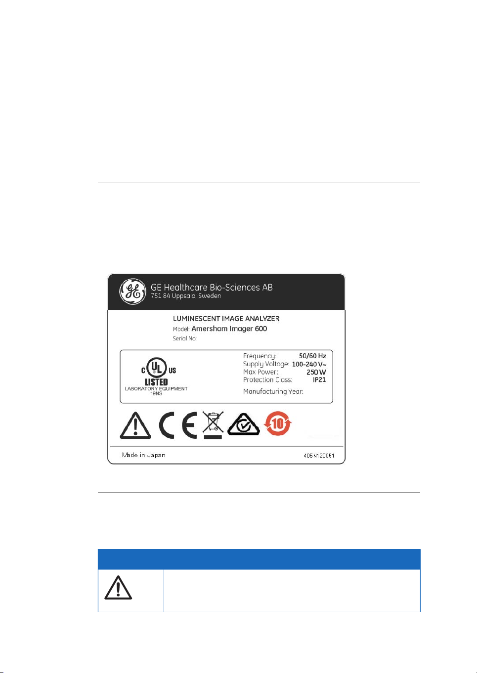
Manufacturing information
The table below summarizes the required manufacturing information. For further information, see the EU Declaration of Conformity (DoC) document.
Conformity with EU Directives
This product complies with the European directives listed in the table, by fulfilling the
corresponding harmonized standards.
A copy of the EU Declaration of Conformity is available on request.
1 Introduction
1.2 Regulatory information
ContentRequirement
GE Healthcare Bio-Sciences AB,Name and address of manufacturer
Björkgatan 30, SE 751 84 Uppsala, Sweden
International Standards
This product fulfills the requirements of the following standards:
IEC/EN 61010-1, IEC
61010-2-010, IEC610102-081, UL 61010-1,
CAN/CSA-C22.2 No.
61010-1
IEC/EN 61326-1,FCC Part
15 B Class A, ICES-003
Class A, EN301 489-1,EN
301 489-17
TitleDirective
Machinery Directive (MD)2006/42/EC
Electromagnetic Compatibility (EMC) Directive2004/108/EC
Safety requirements for electrical
equipment for measurement, control, and laboratory use
Electrical equipment for measurement, control, and laboratory use EMC requirements
NotesDescriptionStandard
EN 61010-1 latest edition
aligned with EN
61010-2-081
EN 61326-1, EN
301 489-1
aligned with
2004/108/EC
Amersham Imager 600 Operating Instructions 29-0645-17 AD 7
Page 8

1 Introduction
1.2 Regulatory information
NotesDescriptionStandard
EN ISO 12100
EN 60529
UL94-V2
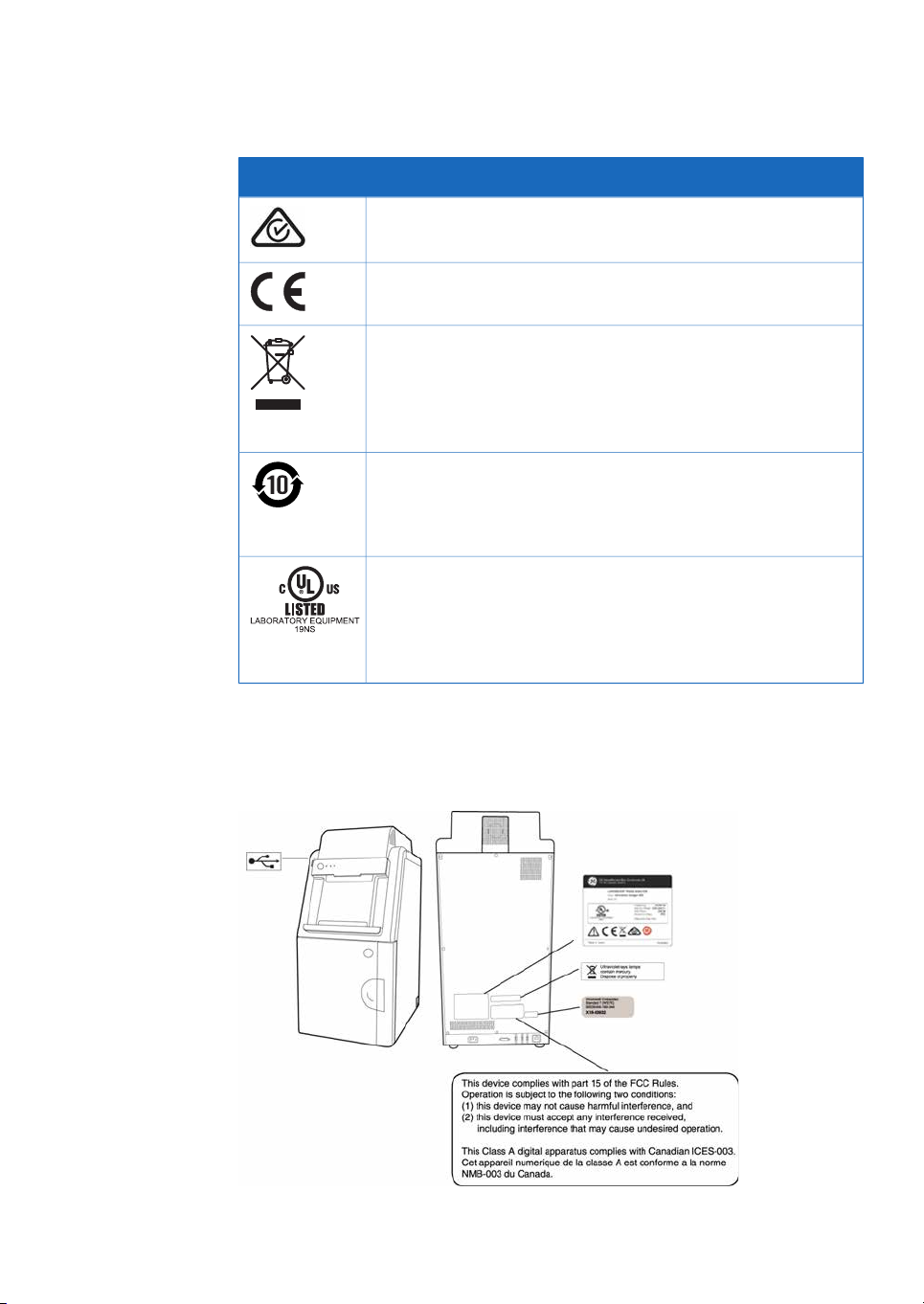
FCC compliance
This device complies with part 15 of the FCC Rules. Operation is subject to the following
two conditions: (1) This device may not cause harmful interference, and (2) this device
must acceptany interference received,including interference that may cause undesired
operation.
Note:
This equipment has been tested and found to comply with the limits for a Class A digital
device, pursuant to part 15 of the FCC Rules. These limits are designed to provide reasonable protection against harmful interference when the equipment is operated in a
commercial environment. Thisequipment generates,uses, andcan radiateradio frequency energy and, if not installed and used in accordance with the instruction manual, may
cause harmful interference to radio communications. Operation of this equipment in a
residential area is likely to cause harmful interference in which case the user will be required to correct the interference at his own expense.
Safety ofmachinery. General principles fordesign. Riskassessment and
risk reduction
Degrees of protection provided by
enclosures
Standard for safety of flammability
of plastic materials for parts in devices and appliances testing
The user is cautioned that any changes or modifications not expressly approved
by GE could void the user’s authority to operate the equipment.
8 Amersham Imager 600 Operating Instructions 29-0645-17 AD
Page 9

CE marking
The CE marking and the corresponding EU Declaration of Conformity is valid for the instrument when it is:
•
used as a stand-alone unit, or
•
connected to other products recommendedor described inthe userdocumentation,
and
•
used in the same state as it was delivered from GE, except for alterations described
in the user documentation.
Environmental Conformity
1 Introduction
1.2 Regulatory information
TitleDirective
Restriction of Hazardous Substances (RoHS) Directive2011/65/EU Annex II
ACPEIP
Regulation (EC) No
1907/2006
Regulatory compliance of
connected equipment
Any electricalequipment connected to Amersham™ Imager600 should meet the safety
requirements of EN/IEC 61010-1, or relevant harmonized standards. Within EU, connected
equipment must be CE marked.
Waste Electricaland ElectronicEquipment (WEEE)Directive2012/19/EU
Administration on the Control of Pollution Caused by Electronic InformationProducts, China Restriction of Hazardous
Substances (RoHS)
Registration, Evaluation, Authorization and restriction of
CHemicals (REACH)
Amersham Imager 600 Operating Instructions 29-0645-17 AD 9
Page 10

1 Introduction
1.2 Regulatory information
Light sources
The safety of the LED light sources in this instrument has been assessed by risk analysis
in accordance with EN 61010-1.
Amersham Imager 600 , depending on configuration, is equipped with some or all light
sources in the table below:
WavelengthLight sources
460 nmBlue LED
520 nmGreen LED
630 nmRed LED
470 nm to 635 nmWhite LED
312 nmTrans-UV-illuminator
10 Amersham Imager 600 Operating Instructions 29-0645-17 AD
Page 11

2 Safety instructions
About this chapter
This chapter describessafety precautions, safety labels, and emergency procedures for
the Amersham Imager 600 instrument, in addition to information on the safe disposal
of the instrument.
In this chapter
2 Safety instructions
See pageSection
122.1 Safety precautions
222.2 Labels
252.3 Emergency procedure
262.4 Recycling information
272.5 Declaration of Hazardous Substances (DoHS)
Amersham Imager 600 Operating Instructions 29-0645-17 AD 11
Page 12
2 Safety instructions
2.1 Safety precautions
2.1 Safety precautions
Introduction
The Amersham Imager 600 instrument is powered by mains voltage, may be equipped
with aUV lightsource, and is usedto capture images of samplesthat maybe hazardous.
Before installing, operating or maintaining the instrument, you must be aware of the
hazards described in the user documentation. Follow the instructions provided to avoid
personal injury or damage to the instrument.
General precautions
WARNING
Do not operate Amersham Imager 600 in any other way than described in the User Manual.
WARNING
Use of this equipment in other ways than those specified in the
user documentation may result in physical damage because of
exposure toirradiated lightor electric shock or injuryfrom touching
an operating part.
WARNING
Do not use the instrument if smoke, atypical noises or odors can
be perceived, or if the instrument becomes unusually hot as this
may result in fire or electric shock.
Stop using the instrument immediately, turn off the power switch,
and unplug the instrument from the power outlet. Contact your
local GE representative to request repair.
12 Amersham Imager 600 Operating Instructions 29-0645-17 AD
Page 13
2 Safety instructions
2.1 Safety precautions
WARNING
Do notdamage thepower supplycord bybending, twisting,heating
or allowing them to become pinned under the equipment. Using
damaged power cords could result in fire or electric shock.
If the power supply cords are damaged, contact your local GE
representative for replacements.
WARNING
Access to power switch and power cord with plug. Do not block
access to the power switch and power cord. The power switch
must always be easy to access. The power cord with plug must
always be easy to disconnect.
WARNING
Do not block vents and ensure that they are kept free of dust and
dirt. Blockagecan causeoverheating andmalfunctioning. To ensure
adequate cooling ensure there is at least 40 cm of free space in
front ofthe instrument and at least 10 cmon all other sides towalls
or other equipment.
Personal protection
WARNING
Hazardous substances. When using hazardous chemicals, take
all suitable protective measures, such as wearing protective
glasses and gloves resistant to the substances used. Follow local
and/or national regulations for safe operation and maintenance
of the system.
Amersham Imager 600 Operating Instructions 29-0645-17 AD 13
Page 14
2 Safety instructions
2.1 Safety precautions
Installation
CAUTION
The instrument is equipped with a safety interlock. If the interlock
is out of order or has been tampered with, UV and visible light may
be emitted, which may cause skin burn and impair vision.
Do not open the instrument door during operation, when the RUN
indicator is lit. If the door is opened and the instrument keeps running, turn off the instrument immediately and contact GE service.
CAUTION
Do not touch the UV unit after UV exposure. There is a risk of skin
burn.
WARNING
As the equipment is heavy, contact a GE service person when
moving or relocating the main body of the equipment. If the
equipment drops, itmay be broken, oryou may get seriously injured
if it drops on your foot.
WARNING
Power cord. Only use power cords with approved plugs delivered
or approved by GE.
WARNING
Protective ground. Amersham Imager 600 must always be con-
nected to a grounded power outlet.
14 Amersham Imager 600 Operating Instructions 29-0645-17 AD
Page 15
2 Safety instructions
2.1 Safety precautions
WARNING
Use a proper power cord that complies with the local laws and
regulations, and is delivered by GE. Do not change power cord to
inappropriate one.
WARNING
In USA and Europe (Belgium, Netherlands, Luxemburg, Germany,
France, Italy, Denmark, Greece, Spain, Portugal, Austria, Finland,
Sweden, Poland, Hungary,Czech, Slovenia,Slovakia, Estonia,Latvia,
Lithuania, and Romania), use the proper power cord included in
the productpackage. Inother countries,use the proper power cord
delivered separately from the product package by GE. Do not
change AC power cord to inappropriate one.
WARNING
Connect thepower supplydirectly toa groundedwall poweroutlet.
The useof extension cords or multiple loads onone electrical outlet
could result in fire and electric shock.
CAUTION
Amersham Imager 600 must be secured before transport or relocation. Contact GE for instructions before transporting the instrument.
NOTICE
Do not connect telephone lines to the Ethernet port.
Only theIEC 60950-I/VL 60950-1 standardnon-shielded cables are
appropriate for connection to this connector.
NOTICE
Only use IEC 60950-1-certified equipment and cables to connect
to the instrument.
Amersham Imager 600 Operating Instructions 29-0645-17 AD 15
Page 16
2 Safety instructions
2.1 Safety precautions
Operation
WARNING
Do not use the instrumentwithin or neara sink, orin humid (above
70% RH) or dusty environments. This can result in fire or electric
shock.
WARNING
In case of thunder, do nottouch the power supply plug, as this can
result in electric shock.
CAUTION
Always useappropriate Personal Protective Equipment(PPE) during
operation and maintenance of Amersham Imager 600.
•
Protective eyewear
•
Protective gloves
•
Protective footware, preferably with steel lining
CAUTION
Reagents usedto prepare thesample shouldbe usedin accordance
with the manufacturer instructions.
CAUTION
Do not lean on the sample door.
CAUTION
Use the handle to open or close the instrument door.
16 Amersham Imager 600 Operating Instructions 29-0645-17 AD
Page 17
2 Safety instructions
2.1 Safety precautions
CAUTION
Do not place heavy objects on top of the instrument.
CAUTION
Handle sample trays and tablet computers with care to avoid
dropping them.
CAUTION
Do not touch the light source in the instrument. The light source
may be hot.
CAUTION
Do notleave samples in the instrumentafter exposure.If left, these
may degrade and cause damage to the instrument.
CAUTION
Do not disable the interlock of the equipment as UV light can be
emitted if the door is opened.
NOTICE
Both the Amersham Imager 600 Control Software and Amersham
Imager 600 Analysis Software do not analyze the image files other
than those captured and generated by Amersham Imager 600.
Analysis offiles otherthan thosecaptured onthe Amersham Imager
600 may introduce errors.
Amersham Imager 600 Operating Instructions 29-0645-17 AD 17
Page 18
2 Safety instructions
2.1 Safety precautions
NOTICE
Do not add and/or remove any files in the folder generated by
Amersham Imager 600 with Amersham Imager 600 Control
Software and Amersham Imager 600 Analysis Software. Do not
modify any folders in which files havebeen addedor removed. This
may prevent a correct analysis afterwards.
NOTICE
Do not use USB ports for recharging external devices. This can
cause instrument malfunction.
NOTICE
Connection of multiple computers to one instrument may impair
performance. Simultaneous use can cause loss of data.
NOTICE
Avoid connecting additional accessories such as computers,
monitors or keyboards to the instrument during operation as this
can stop the exposure or cause loss of data.
NOTICE
Do not turn off power during operation as this can cause loss of
data and damage the Compact flash drive. Only turn off power in
an emergency situation.
NOTICE
Do not open the instrument door during exposure, when the RUN
light indicates operation. This will stop the exposure and data will
not be saved.
18 Amersham Imager 600 Operating Instructions 29-0645-17 AD
Page 19
2 Safety instructions
2.1 Safety precautions
NOTICE
Transferring large amountsof filesto a connected computer during
operation can impair the system’s performance.
NOTICE
Do not touch the light source windows as scratches or dirt may
impair performance.
NOTICE
The tablet computer cannot be recharged with this instrument.
NOTICE
When connectingan externalmonitor to the system, use a monitor
with SVGA resolution. With a low-resolution monitor, operation
buttons cannot be seen.
NOTICE
Remove all traces of acidic solutions to prevent corrosion in the
equipment.
Maintenance
WARNING
Electrical shock hazard. All instrument repairs or modifications
should be performed by service personnel authorized by GE. Do
not open any covers or replace parts unless specifically stated in
the user documentation.
Amersham Imager 600 Operating Instructions 29-0645-17 AD 19
Page 20
2 Safety instructions
2.1 Safety precautions
WARNING
Do notuse excessiveamounts of liquids for cleaning the Amersham
Imager 600 instrument. This may result in instrument malfunction
or electric shock.
CAUTION
Always useappropriate Personal Protective Equipment(PPE) during
operation and maintenance of Amersham Imager 600.
•
Protective eyewear
•
Protective gloves
•
Protective footware, preferably with steel lining
CAUTION
Turn off the power switch before cleaning the inside of the instrument.
CAUTION
UV lamps in Amersham Imager configurations 600 UV, 600 QC,
and 600 RGB containmercury, which mustbe recycled or disposed
of in accordance with local regulations.
NOTICE
Do not use abrasive cleaning materials, such as a scouring pad,
for cleaning. This may cause damage to the instrument.
NOTICE
Dispose of the tablet computer as instructed in its user manual.
20 Amersham Imager 600 Operating Instructions 29-0645-17 AD
Page 21

2 Safety instructions
2.1 Safety precautions
NOTICE
When performingmaintenance ofthe equipment, removethe tablet
computer. There is risk of injury if it falls on your foot.
Amersham Imager 600 Operating Instructions 29-0645-17 AD 21
Page 22
2 Safety instructions
2.2 Labels
2.2 Labels
Introduction
A label on the exterior of the Amersham Imager600 instrument describesthe specifications and precautions necessary to safely use the instrument. This section lists and explains the symbols on the label and the additional symbols used on the instrument.
Amersham Imager 600 system
label
The Amersham Imager 600 instrument serial number is found on the label located on
the back of the instrument.
Symbols used on the labels
The following symbols are found on the label on the instrument:
MeaningLabel
Warning! Read the Operating Instruction before using the system.
Do not open any covers or replace parts unless specifically stated
in the Operating Instruction.
22 Amersham Imager 600 Operating Instructions 29-0645-17 AD
Page 23
2 Safety instructions
2.2 Labels
MeaningLabel
The instrumentcomplies withthe requirementsfor electromagnetic
compliance (EMC) in Australia and New Zealand
The instrument complies with applicable European directives
This symbol indicates that the waste of electrical and electronic
equipment mustnot bedisposed asunsorted municipal waste and
must be collected separately. Please contact an authorized representative of the manufacturer for information concerning the decommissioning of equipment.
This symbolindicates thatthe productcontains hazardousmaterials
in excess of the limits established by the Chinese standard
SJ/T11363-2006 Requirements for ConcentrationLimits for Certain
Hazardous Substances in Electronics.
This symbol indicates that the instrument has been certified by a
Nationally Recognized Testing Laboratory (NTRL). An NRTL is an
organization that the OccupationalSafety andHealth Administration
(OSHA) has recognized as meeting the legal requirements in USA
title 29 of the Code of Federal Regulations (29 CFR) Part 1910.7.
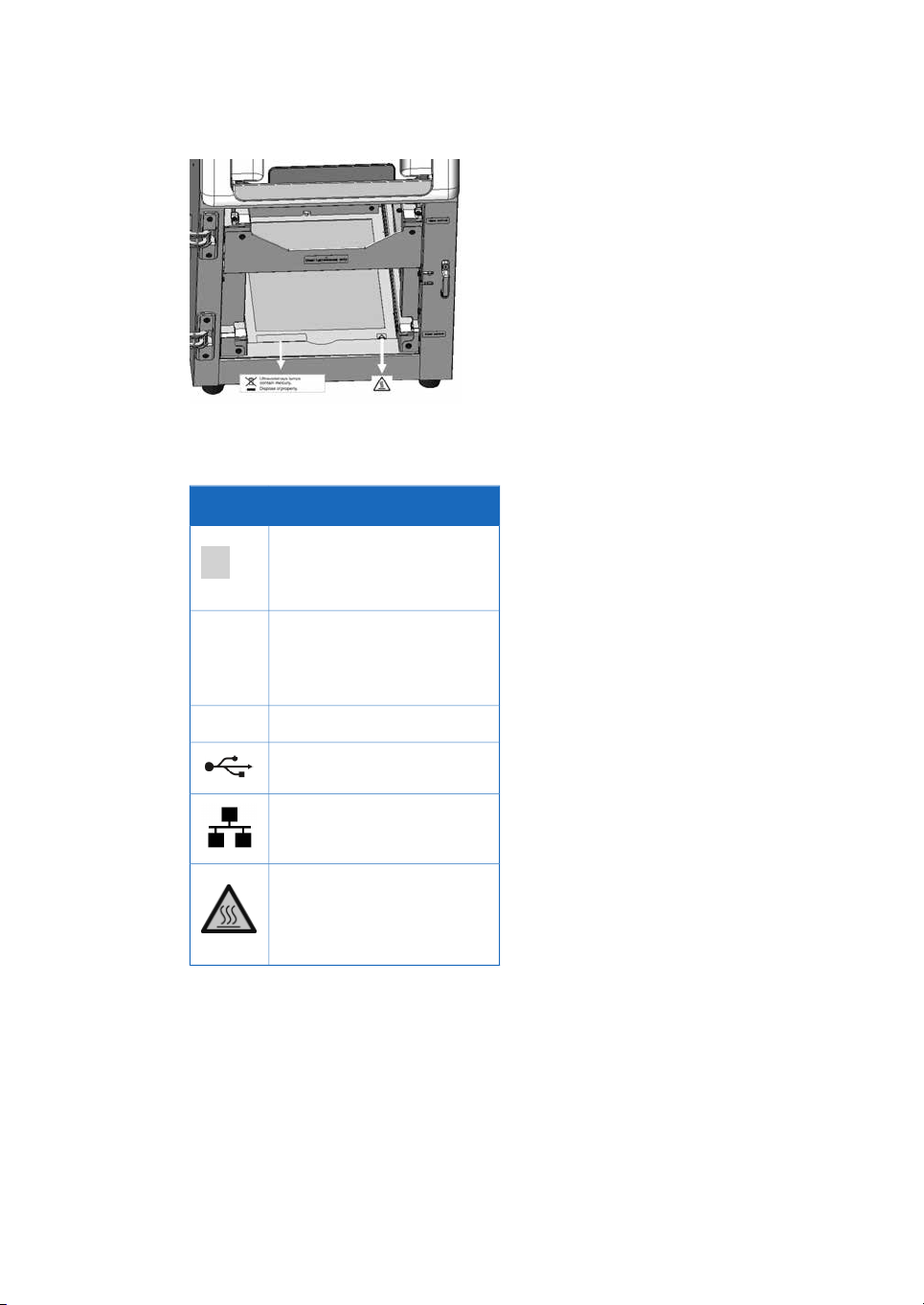
Position of label and additional
symbols
Amersham Imager 600 Operating Instructions 29-0645-17 AD 23
Page 24
2 Safety instructions
2.2 Labels
Note:
For details on symbols see Section 3.4 Instrument hardware description, on
page 33.
DescriptionSymbol
On/Off switch
Power switchI/O
I: Power ON
O: Power OFF
Connector for DVI-D monitorDVI-D
USB port
Ethernet port
Caution, hot surface
24 Amersham Imager 600 Operating Instructions 29-0645-17 AD
Page 25
2.3 Emergency procedure
In case of emergency:
•
Turn off the power by pushing the Power switch to the O position on the bottom
right hand side of the instrument.
•
Disconnect the power cord from the wall socket.
WARNING
Access to power switch and power cord with plug. Do not block
access to the power switch and power cord. The power switch
must always be easy to access. The power cord with plug must
always be easy to disconnect.
2 Safety instructions
2.3 Emergency procedure
Amersham Imager 600 Operating Instructions 29-0645-17 AD 25
Page 26

2 Safety instructions
2.4 Recycling information
2.4 Recycling information
Introduction
This sectioncontains informationabout the decommissioning of Amersham Imager 600.
Decontamination
The equipment and the accessories must be clean from contaminants before decommissioning and all local regulations must be followed with regard to waste disposal.
Samples are to be disposed of according to local regulations.
Disposal, general instructions
When taking the Amersham Imager 600 out of service, the different materials must be
separated and recycled according to national and local environmental regulations.
Recycling of hazardous
substance
The lamps in Amersham Imager 600 configurations: 600 QC, 600 UV, and, 600 RGB
contain mercury vapour. These must be recyled or disposed of in a manner compliant
with national and local environmental regulations.
Disposal of electrical
components
Waste ofelectrical andelectronic equipmentmust notbe disposed as unsorted municipal
waste and must be collected separately. Please contact an authorized representative
of themanufacturerfor informationconcerning the decommissioningof theequipment.
26 Amersham Imager 600 Operating Instructions 29-0645-17 AD
Page 27

2 Safety instructions
2.5 Declaration of Hazardous Substances (DoHS)
2.5 Declaration of Hazardous Substances (DoHS)
根据SJ/T11364-2006《电子信息产品污染控制标识要求》特提供如下有关污染 控制方面的信息。
The following product pollution control information is provided according to SJ/T11364-2006 Marking
for Control of Pollution caused by Electronic Information Products.
电子信息产品污染控制标志说明
Explanation of Pollution Control Label
该标志表明本产品含有超过SJ/T11363-2006《电子信息产品中有毒有害物质的限
量要求》中限量的有毒有害物质。标志中的数字为本产品的环保使用期,表明本
产品在正常使用的条件下,有毒有害物质不会发生外泄或突变,用户使用本产品
不会对环境造成严重污染或对其人身、财产造成严重损害的期限。单位为年。
为保证所申明的环保使用期限,应按产品手册中所规定的环境条件和方法进行正
常使用,并严格遵守产品维修手册中规定的期维修和保养要求。
产品中的消耗件和某些零部件可能有其单独的环保使用期限标志,并且其环保使
用期限有可能比整个产品本身的环保使用期限短。应到期按产品维修程序更换那
些消耗件和零部件,以保证所申明的整个产品的环保使用期限。
本产品在使用寿命结束时不可作为普通生活垃圾处理,应被单独收集妥善处理。
This symbolindicates the product contains hazardous materials in excess of the limits
established bythe Chinesestandard SJ/T11363-2006Requirements for Concentration
Limits for Certain Hazardous Substances in Electronic Information Products. The
number in the symbol is the Environment-friendly Use Period (EFUP), which indicates
the period during which the toxic or hazardous substances or elements contained in
electronic information products will not leak or mutate under normal operating conditions so that the use of such electronic information products will not result in any
severe environmental pollution, any bodily injury or damage to any assets. The unit
of the period is “Year”.
In order to maintain the declared EFUP, the product shall be operated normally according to the instructions and environmental conditions as defined in the product
manual, and periodic maintenance schedules specified in Product Maintenance Procedures shall be followed strictly.
Consumables or certain parts may have their own label with an EFUP valueless than
the product. Periodic replacement of those consumables or parts to maintain the
declared EFUP shall bedone inaccordance withthe ProductMaintenance Procedures.
This product must not be disposed of as unsorted municipal waste, and must be
collected separately and handled properly after decommissioning.
Amersham Imager 600 Operating Instructions 29-0645-17 AD 27
Page 28

2 Safety instructions
2.5 Declaration of Hazardous Substances (DoHS)
有毒有害物质或元素的名称及含量
Name and Concentration of Hazardous Substances
产品中有毒有害物质或元素的名称及含量
Table of Hazardous Substances’ Name and Concentration
Component name
部件名称
The product has not been tested as per the Chinese standard SJ/T11363-2006Requirements for Concentration Limits for Certain Hazardous Substances in Electronic Information Product.
0:
表示该有毒有害物质在该部件所有均质材料中的含量均在SJ/T11363-2006 标准规定的限
量要 求以下
X:
表示该有毒有害物质至少在该部件的某一均质材料中的含量超出SJ/T11363-2006 标准规
定的限量要求
•
0:
此表所列数据为发布时所能获得的最佳信息
Indicates that this toxic or hazardous substance contained in all of the homogeneous materials for this part is below the limit requirement in SJ/T11363-2006.
X:
Indicates that this toxic or hazardous substance contained in at least one of the homogeneous materials used for this part is above the limit requirement in SJ/T11363-2006.
Hazardous substance
有毒有害物质或元素
Pb
铅
Hg
汞
Cd
镉
Cr6+
六价铬
PBB
多溴联苯
PBDE
多溴二苯醚
OOOOOX29-0834-61
OOOXXX29-0834-63
OOOXXX29-0834-64
OOOXXX29-0834-67
•
28 Amersham Imager 600 Operating Instructions 29-0645-17 AD
Data listed in the table represents best information available at the time of publication.
Page 29

3 Instrument description
About this chapter
This chapter presents an overview of Amersham Imager 600 features and different instrument configurations.It alsocontains descriptions of hardwarecomponents, software
displays, and functions.
Note:
Due to cosmetic changes to the software, the screen captures in this manual may
differ sligtly compared to the acutal software. However, the general functions are
the same.
In this chapter
3 Instrument description
See pageSection
303.1 Introduction
313.2 Feature overview
323.3 Illustration of the instrument
333.4 Instrument hardware description
403.5 Instrument software description
593.6 Accessories
Amersham Imager 600 Operating Instructions 29-0645-17 AD 29
Page 30
3 Instrument description
3.1 Introduction
3.1 Introduction
Amersham Imager 600 is an imaging instrument designed to identify and quantify proteins or DNA in gels or membranes. A cooled 3.2 megapixel CCD camera is used to
capture high resolution digital images of protein and DNA bands in gels and on membranes obtained by electrophoresis or western blotting separation methods. The instrument can capture images of chemiluminescent, fluorescent, and colorimetric samples,
depending on the system configuration, and comes with analysis software.
The instrument can be used for research purposes in the academia and life sciences
industry.
30 Amersham Imager 600 Operating Instructions 29-0645-17 AD
Page 31

3.2 Feature overview
The following features are offered by Amersham Imager 600:
•
A highly sensitive CCD camera with 3.2 megapixels
•
Fast detector cooling capacity
•
Ready-to-use within 5 minutes after start-up
•
Tablet computer interface
•
Chemiluminescence imaging with high sensitivity
•
Generation of a combined color image of a chemiluminescence sample image and
a white light image of a color marker
•
Fluorescence imaging using blue, green, and red Epi light sources and UV trans-illuminator
•
Color images of colorimetrically stained gels or membranes obtained by white light
illumination
•
Accurate quantification of stained gels using white trans-illumination
•
Intuitive design with easy to use image analysis workflow
3 Instrument description
3.2 Feature overview
Amersham Imager 600 Operating Instructions 29-0645-17 AD 31
Page 32

3 Instrument description
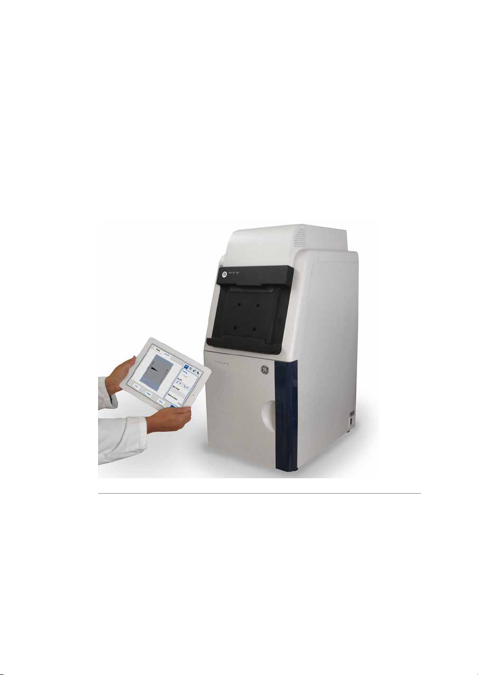
3.3 Illustration of the instrument
3.3 Illustration of the instrument
The Amersham Imager 600 instrument is operated from a wireless connected tablet
computer. It may also be operated from a wired touch screen or a monitor with mouse.
The illustration below displays Amersham Imager 600 setup with tablet computer.
32 Amersham Imager 600 Operating Instructions 29-0645-17 AD
Page 33

3.4 Instrument hardware description
Main components in each
configuration
Amersham Imager 600 is available in four different configurations. Different parts and
functions of Amersham Imager 600 are available depending on configuration.
The table below describes the functions and components of the different instrument
configurations.
3 Instrument description
3.4 Instrument hardware description
Functions
analysis
including lens
Amersham
Imager 600
29-0834-61
Amersham
Imager 600
UV
29-0834-63
Amersham
Imager 600
QC
29-0834-64
Amersham
Imager 600
RGB
29-0834-67
XXXXControl Software for imagecapture and
XXXXChemiluminescence CCD camerahead
XXXXEpi-White light source
XXXFilter changer
XXXTrans-UV light source
XXTrans-White light source
XBlue, Green, and Red Epi light source
Amersham Imager 600 Operating Instructions 29-0645-17 AD 33
Page 34

1
2
3
4
5 6 7 8 9
10 11 12 13
3 Instrument description
3.4 Instrument hardware description
Amersham Imager 600 exterior
The illustrationbelow showsthe main exterior hardwarecomponents ofthe instrument.
DescriptionNamePart
USB port1
2
On/Off button and LED
indicators
A USB 2.0 port for connection of USB flash
drive.
Note:
Password protected USB flash drives are not
supported.
On/Off button: Press the button to turn on
power. Press again to turn off the power.
Power: The LED is lit (white) when the instrument is powered on.
Run: The LED is lit (blue) when the instrument
is operating, or if the Instrument indicator is
selected.
Error: The LED is lit (red) when the instrument
is malfunctioning.
34 Amersham Imager 600 Operating Instructions 29-0645-17 AD
Page 35

3 Instrument description
3.4 Instrument hardware description
DescriptionNamePart
Tablet computer dock3
The dock can hold tablet computers of the
following dimensions and weight:
Width: 222 to 242 mm
Height: 183.5 to 186 mm
Depth: 9.5 mm or less
Weight: 750 g or less
Note:
Some tablet computers cannot fit due to the
shape of corners.
Note:
The tablet computer cannot be recharged on
the instrument.
Note:
With an iPad Air®attachment, iPad Air can be
placed on the dock.
Instrument doorDoor4
Toggle switch:Power switch5
I: Power ON
O : Power OFF
Connector for attaching the AC power cord.Power connector6
Port for connecting a digital only DVI monitor.DVI-D port7
USB port8
Port for additional external devices,for example a printer.
Note:
The tablet computer cannot be recharged with
the instrument.
Connector for a network cable.Ethernet port9
Amersham Imager 600 Operating Instructions 29-0645-17 AD 35
Page 36

1
2
3
4
6
7
8 9 10 11 12 13
5
5
6
3 Instrument description
3.4 Instrument hardware description
Amersham Imager 600 interior
The illustration below shows the main hardware components inside the instrument.
DescriptionNamePart
Guides which support and position the tray.Upper Tray guide1
Guides which support and position the tray.Lower Tray guide2
White lightTrans-White light source3
UV lightTrans-UV light source4
Epi light source5
For configurations 600, 600 UV, and 600 QC:
White light source
For configuration600 RGB: White light plusBlue,
Green, and Red light sources
White lightEpi light source6
Filter changer unitFilter changer7
36 Amersham Imager 600 Operating Instructions 29-0645-17 AD
Page 37

Amersham Imager 600 LED
UP
DOWN
indicators
The table below describes the different states of the LED indicators located at the front
of the instrument, to the right of the On/Off button.
3 Instrument description
3.4 Instrument hardware description
State
Off
on
Mount iPad Air attachment
The descriptionbelow givesthe necessaryinformation for the mounting and dismounting
of the iPad Air attachment to Amersham Imager 600.
POWER
White
light
RUN
Blue light
ERROR
Red light
Indication type and frequency
Flashing ~ 1 HzXPower up
ON = 0.5 s / OFF = 0.5 s
Steady lightXReady / Power
Steady lightXXBusy / Run
Flashing ~ 1 HzXXError
ON = 0.5 s / OFF = 0.5 s
Flashing ~ 1 HzXShutdown
ON = 0.5 s / OFF = 0.5 s
Flashing slowly ~ 0.5 HzXPower save
ON = 0.5 s / OFF = 1.5 s
Mounting the attachment
Note:
Place the attachment as illustrated below.
Amersham Imager 600 Operating Instructions 29-0645-17 AD 37
Page 38

3 Instrument description
3.4 Instrument hardware description
ActionStep
Hold the attachment and slide it upward.1
2
Push the attachment upward firmly into the guide until you hear a clicking
sound.
Connect an iPad Air to the attachment.3
Dismounting the attachment
ActionStep
Push the center of the attachment to release the lock points.1
38 Amersham Imager 600 Operating Instructions 29-0645-17 AD
Page 39

3 Instrument description
3.4 Instrument hardware description
ActionStep
Pull out the attachment downward.2
Amersham Imager 600 Operating Instructions 29-0645-17 AD 39
Page 40

3 Instrument description
3.5 Instrument software description
3.5 Instrument software description
Introduction
The Amersham Imager 600 software is designed to guide you through the workflow of
capturing images and analyzing the image data. The software is normally operated on
a wireless connected tablet computer placed in the dock on the instrument front. This
section describes the main components and functions of the software.
Note:
The software can be controlledfrom a handheld tablet computer,a wire connected
touch screen or a monitor plus mouse.
Note:
The available functions may vary depending on the system configuration.
For details on system configurations see Section 3.4 Instrument hardware descrip-
tion, on page 33.
In this section
This section contains the following:
See pageSection
413.5.1 Description of the Capture tab
463.5.2 Description of the Library tab
483.5.3 Description of the image view
523.5.4 Description of the analysis workflow
553.5.5 Description of settings views
40 Amersham Imager 600 Operating Instructions 29-0645-17 AD
Page 41

3.5.1 Description of the Capture tab
1
2
3
4
5
6
7
9
10
8
Capture view
The Capture tab is displayed as the default start screen when Amersham Imager 600
and the tablet computer are turned on and the start up procedure has finished. It allows
you to select image capturing method and set details for the exposure. The display
changes depending on the choice of method.
The following illustration describes the basic elements of the Capture tab.
3 Instrument description
3.5 Instrument software description
3.5.1 Description of the Capture tab
2
FunctionPart
The selected image capturing method.1
Capture - The tab for selecting image capturing method and starting exposure.
Area displaying options for the selected method.3
The settings icon for accessing the Settings view.4
The help icon for accessing context sensitive online help.5
Start - The start exposure button.6
The date and time.7
Amersham Imager 600 Operating Instructions 29-0645-17 AD 41
Page 42

3 Instrument description
3.5 Instrument software description
3.5.1 Description of the Capture tab
FunctionPart
8
High dynamic range checkbox for image capture withhigh dynamicrange
is available in Auto and Semi-auto capturing methods.
The position of the inserted tray.9
The instrument CCD status displaying one of:10
•
•
Method sensitive displays
The display on the screen shows the selected image capturing method and presents
the options relevant for that method. Depending on system configuration you may or
may nothave access to all methods. The followingsection describesall availablemethod
displays in the Amersham Imager 600 product family.
For details on system configurations see Section 3.4 Instrument hardware description,
on page 33.
Green = The CCD temperature is within specifications and the instrument is ready for use.
Orange = The CCD temperature is not within specifications. Wait for a
green light before proceeding.
42 Amersham Imager 600 Operating Instructions 29-0645-17 AD
Page 43

Chemiluminescence
1
2
3
4
5
The illustration below shows the main components of the Capture tab with the default
setting Chemiluminescence image capturing method and automatic exposure time,
Auto.
3 Instrument description
3.5 Instrument software description
3.5.1 Description of the Capture tab
FunctionPart
1
2
3
5
Amersham Imager 600 Operating Instructions 29-0645-17 AD 43
Chemiluminescence button: the selected chemiluminescence image
capturing method.
Colorimetric marker check box: use the check box forsamples withcolorimetric marker.
Exposure drop down menu:use to select the exposure optionfor chemiluminescence image capturing: Auto , Semi-Auto , Manual, Incremental
and Avanced.
Note:
For more information on manual and incremental settings see Set exposure
time, on page 57.
Start button: use the button to start capturing.4
High dynamic range checkbox: use the checkbox for image capture with
high dynamic range.
Page 44

1
2
3 Instrument description
3.5 Instrument software description
3.5.1 Description of the Capture tab
Colorimetric
The illustration below shows the specific components of the Capture tab with the Colorimetric image capturing method selected.
For more details of the general components, see Capture view, on page 41.
FunctionPart
Colorimetric image capturing method selected1
Options area for the colorimetric image capturing method:2
Epi-illumination (selected here)
•
Trans-illumination
•
Fluorescence
The illustration below shows the specific components of the Capture tab with the Fluorescence image capturing method.Depending on selected options, the display changes
and unavailable options are hidden (greyed out).
44 Amersham Imager 600 Operating Instructions 29-0645-17 AD
For more details of the general components, see Capture view, on page 41.
Page 45

4
1
2
3
3 Instrument description
3.5 Instrument software description
3.5.1 Description of the Capture tab
FunctionPart
Fluorescence image capturing method selected1
Options for the selected image capturing method:2
Epi-RGB
•
Custom (selected here)
•
UV
•
Exposure options:3
Auto (selected here)
•
Semi-Auto
•
Manual
•
Advanced
•
Note:
For more information on manual settings see Set exposure time, on page57.
4
High dynamic range checkbox: Use thecheck box for image capturewith
high dynamic range.
Amersham Imager 600 Operating Instructions 29-0645-17 AD 45
Page 46

1
2 3 4 5 6
7
8
9
10
11
12
13
3 Instrument description
3.5 Instrument software description
3.5.2 Description of the Library tab
3.5.2 Description of the Library tab
The Library tab allows you to find and manage image files.
The illustration below shows the main components of the Library tab.
FunctionPart
1
2
5
The list of files in the selected location. The selected file is highlighted in
blue.
Note:
You may need to scroll or navigate between views to see all files.
The selected file location (here on the instrument): use to view file storage
options, for example USB flash drive or network locations. Select the drop
down menu for more file location options.
Search field: use the field to search for specific files3
Clear button: use the button to clear the search field4
Scroll buttons and bar: use the bar or buttons to navigate among files in
the displayed list of stored files
46 Amersham Imager 600 Operating Instructions 29-0645-17 AD
Page 47

3 Instrument description
3.5 Instrument software description
3.5.2 Description of the Library tab
FunctionPart
6
The selectedSort option: selectthe dropdown menu to view the file sorting
options:
Name - name
•
Date - date
•
Method - method
•
7
The listdisplayed of the number of lists available:use thearrows tonavigate
between lists.
The number of selected files.8
9
Select all/Deselect all button: use the buttons to select all files displayed
or to deselect a selection of files.
Delete button: use the button to delete the selected (marked) file or files.10
Rename button: use the button to rename a saved file.11
Copy/Move button: use the button to copy or move selected files.12
Open button: use the button to open the selected file.13
Amersham Imager 600 Operating Instructions 29-0645-17 AD 47
Page 48

1
2
3
4
5
6 7 8
9
3 Instrument description
3.5 Instrument software description
3.5.3 Description of the image view
3.5.3 Description of the image view
After capturing, the resulting image or images are displayed. The illustration below describes the main components of the image view.
FunctionPart
1
Display of the captured image.
Note:
Incremental and Advanced exposures may result in several images being
displayed two at a time as they are exposed. Navigate among the images
using forward and backward arrows.
48 Amersham Imager 600 Operating Instructions 29-0645-17 AD
Page 49

3 Instrument description
3.5 Instrument software description
3.5.3 Description of the image view
FunctionPart
2
Buttons forcaptured images.A bluetext and frame highlights the displayed
image(s).
Note:
By selecting two or more images a composite image is displayed.
For more information on displayed images for the different capturing
methods see Section 5.5 Capture an image, on page 93.
If the colorimetric marker
option was checked the
tabs will display Sample
and Marker.
If a multichannel fluorescence capture was performed, the tabs will display theselected channels
of Blue, Green, and Red.
3
Information icon:use toaccess additional image and exposure information
such as image file name and exposure time.
Amersham Imager 600 Operating Instructions 29-0645-17 AD 49
Page 50

3 Instrument description
3.5 Instrument software description
3.5.3 Description of the image view
FunctionPart
4
The imagetools menu: use the toolsto modify the settings ofthe captured
image and to view details.
Display
Zoom
Contrast
Intensity tool
For more information on the image tools see Image tools, on page 145.
The selected image tool and options view: Display is the default view.5
6
Done button: Use the button to leave the view without saving.
Note:
A dialog appears asking to confirm the cancellation. This prevents deleting
images by accident.
7
Save button: use the button to save the image. See Section 5.7 Save and
manage image files, on page 148 for further details.
50 Amersham Imager 600 Operating Instructions 29-0645-17 AD
Page 51

3 Instrument description
3.5 Instrument software description
3.5.3 Description of the image view
FunctionPart
8
Analyze button: use the button to open Analyze view. See Section 5.8 Ana-
lyze the image, on page 160 for further details.
9
Print button: use the button to print the image.
Note:
The print function requires that the instrument is connected to a USB connected printer. For installation of a printer contact a representative from
GE.
Amersham Imager 600 Operating Instructions 29-0645-17 AD 51
Page 52

1
2
3
4
5
6
3 Instrument description
3.5 Instrument software description
3.5.4 Description of the analysis workflow
3.5.4 Description of the analysis workflow
This sectiondescribes the analysis workflow options. The workflow allows you to perform
an analysis of the image data. Open the analysis workflow by selecting the Analyze
button. The button is available after capturing or when opening an already captured
image.
The workflow is performed in five steps and results in a summary. After completing a
step, navigate to the next step by selecting the Next button. For more details see Sec-
tion 5.8 Analyze the image, on page 160.
Description
The following illustration shows the start screen and first step of the analysis.
FunctionPart
Contrast button: Use the button to change the contrast of the image.1
Image view button: Use the button to activate the image view.2
3
6
52 Amersham Imager 600 Operating Instructions 29-0645-17 AD
Lane profile button: Use the button to display separate graphical lane
profiles.
Zoom out button: Use the button to zoom out.4
Zoom in button: Use the button to zoom in.5
Analyze workflow buttons: Use the buttons to navigate in the analysis
workflow.
Page 53

Analysis options
The illustration below describes the workflow steps and options.
3 Instrument description
3.5 Instrument software description
3.5.4 Description of the analysis workflow
DescriptionIllustration of stepStep
Open the lane creation step with the button1
Lane Creation is used to define and position lanes to
be used in the subsequent analysis.
Open thebackground subtractionstep withthe button2
Background is used to select method for background
subtraction.
Open the band detection step with the button3
Band Detection is used to detect the bands in each
defined lane.
Amersham Imager 600 Operating Instructions 29-0645-17 AD 53
Page 54

3 Instrument description
3.5 Instrument software description
3.5.4 Description of the analysis workflow
DescriptionIllustration of stepStep
Open the MW calibration step with the button4
MW Calibration is used to create a molecular weight
calibration curvebased on a selected standard marker.
Open the normalization step with the button5
Normalization is used to select bands to be used for
normalization.
Open the summary with the button6
Summary is used to present an overview of the result
data from the analysis.
Use theSave button to save the analysis datatogether
with the image file.
54 Amersham Imager 600 Operating Instructions 29-0645-17 AD
Page 55

3.5.5 Description of settings views
1
2
3
4
5
6
7
8
10
9
This section describes various settings views and options.
General settings view
The settings options found in the Settings view allows you to set specifications for the
instrument. The settings view is displayed by selecting the settings icon:
The illustration below shows the main components of the Settings view. For details see
Section 4.3 System settings, on page 66.
3 Instrument description
3.5 Instrument software description
3.5.5 Description of settings views
FunctionPart
Back button: Use to closethe settingsview and return to the previous view.1
Network button: Use to set up DHCP or Static IP network2
3
Show mouse cursor check box: Use to display a mouse cursor on a connected external monitor by checking the check box.
4
Instrument indicator button: Use to activate the instrument connected
to the tablet computer and light the instrument Run LED light.
Date & Time button: Use to set date and time on the instrument5
Amersham Imager 600 Operating Instructions 29-0645-17 AD 55
7
Focus button: Use to adjust focus6
Sleep button: Use to set the time when the automatic CCD cooling shall
stop after periods of non-use.
Page 56

1 2
3
4
5
6
7
8 9 10
11 12
1 2
4
5
7
8 9 10
3 Instrument description
3.5 Instrument software description
3.5.5 Description of settings views
FunctionPart
Keypad view
8
Service button: Use to viewinstrument serialnumber, version numberand
for accessing Software update and Export log.
9
Analysis software license button: Use to generate license keys for Amersham Imager 600 Analysis Software.
10
Save locations button: Use to add new, edit or remove network locations
for image file storage
The keypad appears when you select text fields where typing is required. Examples of
text fields are: Search, Optional image name prefix, Comment or Rename.
The followingillustration andtable show the main components of thekeypad. Theimage
to the left shows the alphabetic view of the keypad (with lower case letters). The image
to the right shows the numeric and symbol view of the keypad.
FunctionPart
The text field where the typed text is displayed.1
2
Clear button: Use the button to remove all typed text in the text
field.
Keyboard area: Use the keyboard to type text.3
Delete button: Use the button to delete one letter at a time.4
Enter button: Use the button to create a new row.5
Shift button:Use thebutton to change to uppercase letterskeypad.6
56 Amersham Imager 600 Operating Instructions 29-0645-17 AD
Page 57

1
2
3
4
5
6
3 Instrument description
3.5 Instrument software description
3.5.5 Description of settings views
FunctionPart
7
10
11
12
Set exposure time
The Set exposure time view appears when you select Manual or Incremental exposure
in thedrop downmenu and then select the Exposure time button orInterval time button.
It allows you to set the exposure time manually.
The illustration below shows the main components of the Set exposure time view.
Navigation buttons:Use thebuttons to navigate back and forward
in the typed text.
Done button: Use the button to save the changes.8
Space button: Use the button to create a space.9
Cancel button: Use the button to return to the previous window
without saving the changes.
abc button: Use the button to change to the lower case letters
keypad.
@123 button: Use thebutton to change to the numeric andsymbol
keypad.
Note:
Use abc or the ABC button to return to the alphabetic keypad.
Note:
The time displayed in the Set exposure time window, is by default the exposure
time used during the last capture. The time can be set from 0.1 seconds up to 60
minutes.
FunctionPart
Cancel button: Use to return to the Capture tab without saving changes.1
Amersham Imager 600 Operating Instructions 29-0645-17 AD 57
Page 58

3 Instrument description
3.5 Instrument software description
3.5.5 Description of settings views
FunctionPart
Reset button: Use to reset the the exposure time to zero.2
3
Time units area: Use the plus or minus buttons to increase or decrease the
exposure time by Minutes, Seconds, or 1/10 sec.
4
Keypad: Use the right and left arrow buttons to navigate between the
Minutes, Seconds, and 1/10 sec fields. The active field appears blue in the
time units area.
Use the numeric keys to set the time in the selected field.
5
Arrow buttons: Use the buttons to navigate between minutes, seconds,
and 1/10 s in the time units area.
Set button: Use the button to save the changes made.6
58 Amersham Imager 600 Operating Instructions 29-0645-17 AD
Page 59

3.6 Accessories
Accessories delivered with the
instrument
The following table shows the accessories of Amersham Imager 600. Depending on
configuration the included accessories may vary.
3 Instrument description
3.6 Accessories
Black Tray
UV Trans Tray
(transparent)
marked White Trans
Tray
Code no.DescriptionPart
Relevant for configuration:
All configurations29-0834-17Black tray, marked
600 UV29-0834-19UV Trans tray, marked
600 QC
600 RGB
600 QC29-0834-18White Trans tray,
600 RGB
All configurations29-0880-60White Insert, marked
White Insert
(for usewith Black Tray
where applicable)
Amersham Imager 600 Operating Instructions 29-0645-17 AD 59
Page 60

3 Instrument description
3.6 Accessories
Diffuser Board
(for whitelight Trans-illumination)
Operating Instructions
tions of Amersham
Imager 600 Operating
Instructions
Analysis Software
Code no.DescriptionPart
Relevant for configuration:
600 QC29-0834-20Diffuser Board, marked
600 RGB
All configurations29-0645-17Amersham Imager 600
All configurations29-0902-97DVD containingtransla-
All configurations29-1540-84Amersham Imager 600
All configurations19-2448-01AC power cord (for
North America)
All configurations80-6480-33AC power cord (for Eu-
rope)
60 Amersham Imager 600 Operating Instructions 29-0645-17 AD
Page 61

Additional accessories to order
3 Instrument description
3.6 Accessories
Upgrade options
UV-Trans tray)
Code no.DescriptionPart
Code no.Part/Description
Relevant for configuration:
600 UV29-0834-57Gel Sheets 17x25 (for
600 QC
600 RGB
All configurations29-1338-29iPad Air attachment
Relevant for configuration:
60029-0834-22AI600 Upgrade 600 to 600 UV
600 UV29-0834-24AI600 Upgrade 600 UV to 600 QC
600 QC29-0834-25AI600 Upgrade 600 QC to 600 RGB
600 UV29-0834-26AI600 Upgrade 600 UV to 600 RGB
Amersham Imager 600 Operating Instructions 29-0645-17 AD 61
Page 62

4 Installation
4 Installation
About this chapter
This chaptercontains informationon how to preparethe site for Amersham Imager600,
how to set up network connections, and set system settings.
Note:
Installation or transport of the Amersham Imager 600 instrument must be performed by GE authorized personnel. The instrument contains parts that may be
damaged unless they are secured for transportation and handled correctly.
In this chapter
See pageSection
634.1 Site requirements
654.2 Instrument setup
664.3 System settings
744.4 Network
62 Amersham Imager 600 Operating Instructions 29-0645-17 AD
Page 63

4.1 Site requirements
Environmental conditions
The following table describes the environmental requirements for Amersham Imager
600.
CAUTION
Do not use the instrument in a room with a temperature above
+28°C. Higher temperatures does not allow the CCD to cool down
properly (to -25°C).
ConditionParameter
Front of instrument (the operation panel side): 40 cmFree space required around
Amersham Imager 600
Right: 10 cm
Left: 10 cm
4 Installation
4.1 Site requirements
Placement
Other conditions
Rear: 10 cm
Top: 10 cm
A stable laboratory bench with a load capacity of 980 N (100 kg) or
higher
The bench must be level within 2º (two) degrees.
Take into consideration theworkflow andancillary facilitieswhen
1
planning the installation.
Any required construction and electricity/air conditioning work
2
must be completed prior to installation.
It is not desirable to have a heat source near the Amersham
3
Imager 600 air intakes, even if the other environmental requirements have been met.
Do notinstall the equipment near a window. Avoiddirect sunlight.
4
Ensure blinds are attached to nearby windows.
Do notplace objectsnear the power outlet to ensure easy access
5
to the power cord for disconnection in case of emergency.
Amersham Imager 600 Operating Instructions 29-0645-17 AD 63
Page 64

4 Installation
4.1 Site requirements
ConditionParameter
Operating temperature/humidity
conditions
conditions
Temperature:18°C to 28°C (with temperature fluctuation below 10ºC
per hour or lower)
Humidity: 20% to 70% RH (no dew condensation)
Note:
When the above conditions cannot be satisfied, take appropriate
actions.
Temperature: -25°C to 70°CTransportation/storage
Humidity: 5% to 95% RH (no dew condensation)
Note:
When the above conditions cannot be satisfied, take appropriate
actions.
Do not install the instrument:Installation location conditions
where the temperature can vary widely (with temperature fluc-
1
tuation above 10ºC per hour)
near a heat source such as a radiator
2
where it may get wet or flooded.
3
where it may be exposed to corrosive gas
4
in a dusty environment
5
in a place constantly or excessively exposed to vibration or im-
6
pacts
in a place exposed to direct sunlight
7
Indoor useOperation site
2000 m or lowerMaximum operating altitude
70 dB(A) or lowerNoise
Fast Lmax≤60dB(A), andaverage Leq ≤ 54dB(A) (1 m from the instrument)
IP21Protection provided by enclosure
Transient overvoltage category IIOvervoltage category
Pollution degree 2Rated pollution applied
64 Amersham Imager 600 Operating Instructions 29-0645-17 AD
Page 65

4.2 Instrument setup
Introduction
Amersham Imager 600 is initially installed by GE service representatives.
Amersham Imager 600 must be secured before long distance transports. Contact GE
for instructions before transport or relocation of the instrument.
For connectingadditional monitors or peripheral equipmentcontact GE for instructions.
4 Installation
4.2 Instrument setup
Amersham Imager 600 Operating Instructions 29-0645-17 AD 65
Page 66

4 Installation
4.3 System settings
4.3 System settings
Introduction
This section describes how to set system specific settings.
System settings are found under the Settings view. Open the settings view by selecting
the settings icon found in the top right hand corner of the Capture and Library tabs.
For thegeneral components of the Settings view see Section 3.5.5 Description of settings
views, on page 55
66 Amersham Imager 600 Operating Instructions 29-0645-17 AD
Page 67

4.3.1 Date and time
Date and time view
The following illustration describes the Date & Time view.
4 Installation
4.3 System settings
4.3.1 Date and time
Change date
FunctionPart
1
2
3
4
To change the date setting on the instrument, select the plus or minus buttons next to
the Year, Month, and/or Day field, to change the value of year, month or day.
Cancel button: Use the button to return to the Settings window without
saving the changes.
Date field: Use the plus and minus buttons next to Year, Month, and Day
to set values for year, month, and day.
Time field: Use the plus and minus buttons next to Hour and Minute to set
values for hour and minute.
Ok button: Use thebutton tosave the changes to date and time and return
to the Settings window.
Amersham Imager 600 Operating Instructions 29-0645-17 AD 67
Page 68

4 Installation
4.3 System settings
4.3.1 Date and time
Change time
To change the time setting on the instrument, select the plus or minus buttons next to
the Hour or Minute field, to change the value of hour or minute.
Save the changes to date and
time
Select the Ok button to save the changes to the Date & time view.
Select the Cancel button to leave the view without saving changes.
68 Amersham Imager 600 Operating Instructions 29-0645-17 AD
Page 69

4.3.2 Focus
1 2 3 4
5
6
7
8
9
10
11
12
Focus view
The focus is normally fixed. For thick samples this fixed focus may not be adequate and
you may need to temporarily adjust it.
4 Installation
4.3 System settings
4.3.2 Focus
FunctionPart
The image area which displays the image of sample.1
Double arrow buttons: Use the buttons to adjust focus in larger steps.2
The focus value.3
Single arrow buttons: Use the buttons to adjust focus in smaller steps.4
5
Default button: Use the button to reset focus to the default value.
Note:
The default value differs between instruments.
The brightness value.6
Plus and minus buttons: Use the buttons to adjust the brightness value.7
OK button: Use the button to save the new settings.8
Cancel button: Use the button to leave the view without saving changes.9
Amersham Imager 600 Operating Instructions 29-0645-17 AD 69
Page 70

4 Installation
4.3 System settings
4.3.2 Focus
Adjust focus
ActionStep
1
3
4
5
6
Prepare andplace a sample on a tray andplace the tray in the instrument's
lower tray position.
If relevant, point to an area of interest to zoom in on.2
Adjust the brightness of the image to a satisfactory level by using the plus
and minus buttons next to the Brightness value.
Adjust thefocus to a satisfactory level byusing the arrows above and below
the Focus value.
Select OK to save the settings.
Note:
Cancel will close the view without saving changes.
The new focus will be available for captures until a new capturing method
is selected, or until the instrument enters standby mode.
Prior to the capture confirm the use of thenew focus with Yes. Selecting the
No button cancels the adjustments to focus and the normal fixed focus
setting (default) is once again in use.
70 Amersham Imager 600 Operating Instructions 29-0645-17 AD
Page 71

4.3.3 Instrument indicator
The Instrumentindicator is a usefultool when several Amersham Imager 600 instruments
are used in the same location. It identifies which instrument is connected to a certain
tablet computer.
Select theInstrument indicator button. This activates theRun LED light on theinstrument
it is connected to.
4 Installation
4.3 System settings
4.3.3 Instrument indicator
Amersham Imager 600 Operating Instructions 29-0645-17 AD 71
Page 72

4 Installation
4.3 System settings
4.3.4 Service
4.3.4 Service
Introduction
In the Service view the following information can be found:
•
Instrument serial number
•
Software version
•
Firmware version
•
FPGA version
The view also displays buttons for software update and export log functions.
Update software
Follow the instructions below to update the software for Amersham Imager 600.
ActionStep
1
72 Amersham Imager 600 Operating Instructions 29-0645-17 AD
Connect a USB flash drive containing the update file provided by GE stored
at the root level of the USB flash drive.
Select the Software update button.2
Confirm USB insertion by selecting the OK button.3
Select the Yes button to update the software.4
Page 73

4 Installation
4.3 System settings
4.3.4 Service
ActionStep
To return to the Settings window select the OK button.5
Export log
6
Follow the instructions below to export a log from Amersham Imager 600.
Confirm the software, Firmware and FPGA version numbers are correctly
updated.
ActionStep
Select the Export log button.1
Result: A textfile will be created on theinstrument containing theexport log
file.
Insert a USB flash drive and confirm insertion by selecting the OK button.2
Result: The export log file will be transferred to the USB flash drive.
To return to the Settings view, select the OK button.3
Amersham Imager 600 Operating Instructions 29-0645-17 AD 73
Page 74

4 Installation
4.4 Network
4.4 Network
Introduction
Via a network connection you can save image files to a network location, access files
stored on a network location from the instrument and copy and delete image files from
a computer.
This section contains information on network setup options, virus protection, network
settings, and file access.
In this section
See pageSection
754.4.1 Network setup
794.4.2 Network access from instrument
814.4.3 Instrument access from network
74 Amersham Imager 600 Operating Instructions 29-0645-17 AD
Page 75

4.4.1 Network setup
Virus protection
The technical solution for Amersham Imager 600 protects it from virus transfer from infected USB flash drives. Each restart of the instrument resets the software to its original
installation.
Note:
If you, for any reason, suspect that the instrument has been infected by a computer
virus, restart the instrument as soon as possible.
Network connection options
NOTICE
Do not connect telephone lines to the Ethernet port.
Only theIEC 60950-I/VL 60950-1 standardnon-shielded cables are
appropriate for connection to this connector.
4 Installation
4.4 Network
4.4.1 Network setup
Connection to a network enables the instrument to access files from, and to save files
to, a network location.
There are two options for network setup:
1
DHCP
2
Static IP
Note:
If a DHCP network is used the IP address will be assigned automatically by the
DHCP server. If a Static IP network is used the network details have to be entered
manually.
Amersham Imager 600 Operating Instructions 29-0645-17 AD 75
Page 76

4 Installation
4.4 Network
4.4.1 Network setup
Connect to network
Follow the instructions below to connect to a Network:
1
ActionStep
Select the settings icon.
Result: The Settings view will appear.
Select the Network button.2
Result: The Network view will appear.
3
Select the type of network connection and follow the separate instructions
below.
Connect to a DHCP network
Follow the instructions below, to connect to a DHCP network:
76 Amersham Imager 600 Operating Instructions 29-0645-17 AD
Page 77

4 Installation
4.4 Network
4.4.1 Network setup
ActionStep
Connect the network cable to the Ethernet port on Amersham Imager 600.1
Check the DHCP radio button in the Network window.2
3
If desired, check the Workgroup field and use the keypad to enter the
workgroup.
Note:
For detailed information on how to use the keypad, see Keypad view, on
page 56.
Select OK.4
Result: An automatic connection to the DHCP network is established within
a couple of seconds.
Tip:
Reserve the IP address to Amersham Imager 600 for easier access of its network resources.
Connect to a Static IP network
Follow the instructions below, to connect to a Static IP network:
ActionStep
Connect the network cable to the Ethernet port on Amersham Imager 600.1
Amersham Imager 600 Operating Instructions 29-0645-17 AD 77
Page 78

4 Installation
4.4 Network
4.4.1 Network setup
ActionStep
Check the Static IP radio button in the Network window.2
Select the:3
IP address field and use the keypad to enter the IP address.
1
Subnet mask field and use the keypad to enter the subnet mask.
2
If desired, select the :
Gateway field and use the keypad to enter the router.
•
Workgroup field and use the keypad to enter the workgroup.
•
Select OK to save the changes.4
Result: The connection to the network will be established within a couple of
seconds.
78 Amersham Imager 600 Operating Instructions 29-0645-17 AD
Page 79

4.4.2 Network access from instrument
To be able to store and access files on a network location, Amersham Imager 600 must
have access permission to the specific computer or server where the files are to be
stored.
The exact procedure for setting permissions for network file sharing depends on the
computer's Operative System (OS) and your organization's network security settings.
Note:
Contact your GE representative for optional OS instructions or refer to your local
IT support or your own computer's help files.
OS Windows®7 instructions
ActionStep
4 Installation
4.4 Network
4.4.2 Network access from instrument
1
4
10
On the computer: Open Control panel:System and Security:System and
write down the name of the computer (the network identification name).
Create a new folder and name the folder:2
Example: "AmershamImager600".
Right-click on the folder and select Properties:Share with.3
Select which user or group you wish to grantpermission (for example users)
and check the check box Full control.
Note:
Limited permissions, such as Read, will not allow the instrument to export or
analyze saved files on the computer.
Select Share.5
Note the full computer name and go to the instrument.6
On the instrument: Select the settings icon.7
Select the Save locations button.8
Select the Add new button.9
Browse to the location, or type the name of the computer in the field Loca-
tion.
Example: "//HXX-DTKJ8Q9.clients.region.division.compa-
ny.com/AmershamImager600"
Amersham Imager 600 Operating Instructions 29-0645-17 AD 79
Page 80

4 Installation
4.4 Network
4.4.2 Network access from instrument
ActionStep
Select OK.11
Result: This will allow for sharing files from the computer to the instrument
and from the instrument to the computer for users.
Note:
If password-protected sharing is turned on, you must have a user account and
password on your computer for full access to shared items. Password-protected
sharing is located in the Control panel under Advanced sharing settings. Password protection is turned on by default.
80 Amersham Imager 600 Operating Instructions 29-0645-17 AD
Page 81

4.4.3 Instrument access from network
Amersham Imager600 isequipped with a web tool which allows instrument accessfrom
a network. The web tool can be used to copy or delete files on the instrument from a
remote location.
To be able to access Amersham Imager 600 web tool the following conditions must be
fulfilled:
•
The instrument and the computer must be connected through a local network.
•
The instrument's IP address must be known.
Your instrument's IP address is found in the Network view. Open the view by selecting
the settings icon in the top right hand corner and then select the Network button in the
Settings view.
Note:
DHCP networks has a dynamic IP address assignment, therefore the IP address
may vary between connections. When using a DHCP network connection, check
regularly that the IP address is still accurate. If the IP address has changed, use
the new IP address in the Network view.
Access the web tool
Follow the steps below to set up and access files via the web tool.
4 Installation
4.4 Network
4.4.3 Instrument access from network
ActionStep
Open the computer's web browser.1
Amersham Imager 600 Operating Instructions 29-0645-17 AD 81
Page 82

4 Installation
4.4 Network
4.4.3 Instrument access from network
ActionStep
2
Type the instrument's IP address in the browser address field and select
enter.
Example: http://192.168.0.25:8080
Result: A page asking for password is displayed.
Note:
The password can be changed. Press Option in the Login window and follow
the instruction in the Options window.
82 Amersham Imager 600 Operating Instructions 29-0645-17 AD
Page 83

4.4.3 Instrument access from network
ActionStep
Type the default password: AI600user and select Login.3
Result: This opens the Amersham Imager 600 web tool page.
4 Installation
4.4 Network
Use the search function to limit the list.4
Search by date: Use the date format YYYY-MM-DD
•
Example: "2013-11-30"
Search by keyword
•
Select Search to perform the search.
Delete the information in the search fields and select Search to reset the
list.
5
Select the files to be copied or deleted by checking the file's check box.
Note:
A maximum number of 5 files can be copied at one time. You may repeat this
step to copy additional files.
6
Select the Copy button to copy the selected files.
•
Select the Delete button to delete the selected files.
•
Note:
The copied files will be downloaded as a zip-file with an automatically generated name. The download location and procedure will vary with the chosen
web browser's download settings.
Amersham Imager 600 Operating Instructions 29-0645-17 AD 83
Page 84

5 Operation
5 Operation
About this chapter
This chapter describes how to operate Amersham Imager 600.
Prior to operating the Amersham Imager 600 system it is important that you have read
and understoodthe safety information. Make sure to read the relevant safety instructions
prior to operation. See Section 2.1 Safety precautions, on page 12 for details.
In this chapter
WARNING
Do not operate Amersham Imager 600 in any other way than described in the User Manual.
See pageSection
855.1 Operation flow chart
865.2 Turn on the instrument
895.3 Select tray
905.4 Place the tray in the instrument
935.5 Capture an image
1445.6 View the image
1485.7 Save and manage image files
1605.8 Analyze the image
1775.9 Turn off the instrument
84 Amersham Imager 600 Operating Instructions 29-0645-17 AD
Page 85

5.1 Operation flow chart
Select a tray and place sample
Place the tray in the instrument
Capture the image
Analyze the image
Save the image file
Turn on the instrument
The general flow of operation is as follows:
5 Operation
5.1 Operation flow chart
Amersham Imager 600 Operating Instructions 29-0645-17 AD 85
Page 86

5 Operation
5.2 Turn on the instrument
5.2 Turn on the instrument
The following section describes the startup process.
Note:
If using a wired external monitor or touch screen it must be connected to the instrument before start up.
ActionStep
1
Turn onpower tothe instrumentby pressingthe Power switch on the bottom
right side of the instrument to the I position.
Press the On/Off button on the front of the instrument to activate it.2
Result: The instrument's self-diagnostic process will initialize.
Note:
The self-diagnostic process will normally take approximately 5 minutes.
Connection to a network may take longer.
If relevant, connect a USB flash drive to the instrument for file storage.3
The USB flash driver is automatically installed when the USB flash drive is
connected to Amersham Imager 600.
Note:
Password protected USB flash drives are not supported.
86 Amersham Imager 600 Operating Instructions 29-0645-17 AD
Page 87

5 Operation
5.2 Turn on the instrument
ActionStep
4
Select the icon for Amersham Imager 600 on the desktop screen of the
connected tablet computer.
Result:
1. A welcome screen appears.
2. The following screen will be displayed.
Amersham Imager 600 Operating Instructions 29-0645-17 AD 87
Page 88

5 Operation
5.2 Turn on the instrument
ActionStep
Select the Continue button.5
Result: The following screen will be displayed.
Wait for the CCD status to turn green.6
Result: Image capturing can begin.
88 Amersham Imager 600 Operating Instructions 29-0645-17 AD
Page 89

5.3 Select tray
The followingtable describesthe suitable tray and accessory for eachcapturing method.
Note:
Use the correct tray to the selected exposure for optimal image quality.
5 Operation
5.3 Select tray
Tray and accessorySample typeImage capturing method
Chemiluminescence
Chemiluminescence
with colorimetric marker 600 UVWhite Insert
Colorimetric
Epi-illumination 600 UV
Colorimetric
Trans-illumination 600 RGBDiffuser Board
Fluorescence RGB
Epi-illumination
Membrane
•
Membrane
•
Membrane
•
Gel
•
Gel
•
Gel
•
Membrane
•
White Insert or,
White Trans Tray
Available in
configuration
600Black Tray
600 UV
600 QC
600 RGB
600Black Tray +
600 QC
600 RGB
600Black Tray +
600 QC
600 RGB
600 QCWhite Trans Tray +
600 RGBBlack Tray
Fluorescence
Trans-UV 600 QC
Gel
•
(transparent) +
Gel sheet
600 UCUV Trans Tray
600 RGB
NOTICE
With regards to third party patents related to sample preparation
etcetera, werecommend thatyou consulta lawyeror patent attorney on obtaining appropriate licenses.
Amersham Imager 600 Operating Instructions 29-0645-17 AD 89
Page 90

5 Operation
5.4 Place the tray in the instrument
5.4 Place the tray in the instrument
Place the tray
This section describes how to place the sample on the tray and how to place the tray in
the correct tray position in Amersham Imager 600.
ActionStep
Select a tray and accessories suitable for the capturing method.1
2
For Chemiluminescence with colorimetric marker and Colorimetric Epi
capturing, place the White Insert inside the Black Tray.
90 Amersham Imager 600 Operating Instructions 29-0645-17 AD
Page 91

5 Operation
5.4 Place the tray in the instrument
ActionStep
Place the sample(s) on the tray or on the White Insert.3
Take care not to cover the areas outside any visible markings on the tray,
or the White Insert, as they mark the field of view.
It is possible to place more than one membrane or gel provided they fit into
the field of view.
There are two alternative tray positions with different fields of view:
One side indicates the maximum field of view of 8 x 11 cm for the upper
1
tray position.Use the upper tray position for Chemiluminescencecapturing fora smaller field of view of asingle membraneand shorter exposure
time.
The other side indicates the maximum field of viewof 16 x 22 cm for the
2
lower tray position. Use the lower tray position for a larger field of view
for one to four samples.
Amersham Imager 600 Operating Instructions 29-0645-17 AD 91
Page 92

1
2
5 Operation
5.4 Place the tray in the instrument
ActionStep
Note:
For Colorimetric Epi-illumination position the gel so that the lanes are parallel to the long side of the tray as illustrated below. This is important to avoid
capturing artefacts in the image.
Open the instrument door.4
5
Insert the tray in the correct tray position.
Note:
For Chemiluminescence capturing you may also select the upper tray position
(1 in the illustration below).
Close the door.6
92 Amersham Imager 600 Operating Instructions 29-0645-17 AD
Page 93

5.5 Capture an image
This section describes how to capture an image with any of the available methods.
In this section
5 Operation
5.5 Capture an image
See pageSection
945.5.1 Available methods
955.5.2 Chemiluminescence capture
1185.5.3 Colorimetric capture
1225.5.4 Fluorescence capture
Amersham Imager 600 Operating Instructions 29-0645-17 AD 93
Page 94

5 Operation
5.5 Capture an image
5.5.1 Available methods
5.5.1 Available methods
This section describes how to capture an image.
The table below describes the available methods for each Amersham Imager 600 configuration:
(single channel or multichannnel)
with colorimetric marker (single channel)
NOTICE
Do not open the instrument door during exposure, when the RUN
light indicates operation. This will stop the exposure and data will
not be saved.
600
600Method
UV
600
QC
600
RGB
xxxxChemiluminescence
xxxxChemiluminescence - with colorimetric marker
xxxxColorimetric - Epi-illumination
xxColorimetric - Trans-illumination
xxxFluorescence - UV trans-illumination
xFluorescence -Blue, Green,Red, Epi-illumination
xFluorescence -Blue, Green,Red, Epi-illumination
94 Amersham Imager 600 Operating Instructions 29-0645-17 AD
Page 95

5.5.2 Chemiluminescence capture
1
2
Introduction
The chemiluminescence image capture method is available in all configurations of
Amersham Imager 600. The instrument captures the light which is emitted during the
chemical reaction on the membrane. When a colorimetric marker is present in the
sample, an additional color image can be captured using a white light source.
Chemiluminescence image capture is performed
on oneto fourmembranes placedon a Black Tray.
Chemiluminescence imagecapturewith colorimetric markers is performed on one to four membranes placed on a Black Tray with a White In-
sert.
5 Operation
5.5 Capture an image
5.5.2 Chemiluminescence capture
Note:
The White Insert has 2 sides, one for upper tray
position and the other for the lower tray position.
There are two alternative tray positions:
Upper tray position:
1
Use the upper tray position for a
smaller field of view of a single
membrane and shorter exposure
time.
The field of view is 8 x 11 cm.
Lower tray position:
2
Use the lower tray position for a
larger field of view for one to four
membranes.
The field of view is 16 x 22 cm
Amersham Imager 600 Operating Instructions 29-0645-17 AD 95
Page 96

5 Operation
5.5 Capture an image
5.5.2 Chemiluminescence capture
Chemiluminescence exposure
options
There are five exposure options for Chemiluminescence capturing. The table below
suggests the options to use in different situations.
range is required:
Then...When...
Select Auto for automatic exposure.An optimal dynamic
A short pre-exposure isperformed to determine the signal
intensity. Thesystem willuse thisinformation tocalculate
which exposure time will give the highest possible signal
below saturationto enable accurate quantification of the
sample.
To use the fulldynamic rangeof the image file, checkHigh
dynamic range.
To minimize exposure time, leave High dynamic range
unchecked.
Select Semi-automatic.A specific area of a
sample is of interest:
96 Amersham Imager 600 Operating Instructions 29-0645-17 AD
A short pre-exposure is performed which results in an
image. This allows you to select the area of the sample
image to focus on. Thesoftware automaticallycalculates
the optimal exposure time for the specified area.
To use the fulldynamic rangeof the image file, checkHigh
dynamic range.
To minimize exposure time, leave High dynamic range
unchecked.
Page 97

5 Operation
5.5 Capture an image
5.5.2 Chemiluminescence capture
Then...When...
The intensity of the
image is inadequate after automatic exposure
or a known exposure
time is required:
A sequenceof images is
required:
parameters is required
for special applications:
Note:
Do not open the door during exposure as this will stop the exposure and the data
will not be saved.
Chemiluminescence with
automatic exposure time
Follow the instructions below to perform chemiluminescence capture using automatic
exposure time.
ActionStep
In the Capture tab, select Chemiluminescence.1
Result: The options availablefor Chemiluminescencecapturing aredisplayed
to the right on the screen. Automatic exposure is selected by default and
the Exposure options field displays Auto.
Select Manual exposure and set the exposure time manually.
Select Incremental exposure andset thenumber of repe-
titions and interval time of the exposures to capture sequential images.
Select Advanced exposureFull control of exposure
Amersham Imager 600 Operating Instructions 29-0645-17 AD 97
Page 98

5 Operation
5.5 Capture an image
5.5.2 Chemiluminescence capture
ActionStep
2
If your sample contains a colorimetric marker, then select the check box
Colorimetric marker.
To use the full dynamic range of the image file, check High dynamic range.3
To minimize exposure time, leave High dynamic range unchecked.
Select Start.4
Result: The exposure will begin following a pre-exposure. A progress bar
appears onthe screenindicating the time remaining of the imaging process,
the exposure selected and the calculated remaining time.
Note:
Selecting Cancel will cancel the exposure and the Capture view will appear.
98 Amersham Imager 600 Operating Instructions 29-0645-17 AD
Page 99

5 Operation
5.5 Capture an image
5.5.2 Chemiluminescence capture
ActionStep
5
When the exposure is finished the image view appears displaying the image(s). AmershamImager 600creates afolder containing the createdimage
files which can be saved. For details see File formats, on page 154.
Then...If...
The resulting image is displayed in gray scale.No colorimetric marker
was used
Colorimetric
marker was
used
The resulting images are displayed under Sample and
Marker tabs.
Select the relevant tab for the image you wish to
•
display. A selected tab is highlighted with blue text
and frame.
Select bothtabs simultaneouslyto see a composite
•
color image of the Sample and Marker images.
Select the Save button to save the images.6
For other options after capturing see Options after capturing, on page 117.
Amersham Imager 600 Operating Instructions 29-0645-17 AD 99
Page 100

5 Operation
5.5 Capture an image
5.5.2 Chemiluminescence capture
Chemiluminescence with
semi-automatic exposure
Follow the instructions below to perform chemiluminescence capture using semi-automatic exposure time.
ActionStep
In the Capture tab, select Chemiluminescence.1
Result: The options availablefor chemiluminescencecapturing aredisplayed
to the right on the screen.
2
If your sample contains a colorimetric marker, then select the check box
Colorimetric marker.
To use the full dynamic range of the image file, check High dynamic range.3
To minimize exposure time, leave High dynamic range unchecked.
Select Semi-Auto exposure in the exposure drop down menu.4
Select Next and wait for the pre-exposure to finish.5
100 Amersham Imager 600 Operating Instructions 29-0645-17 AD
 Loading...