

Page 1
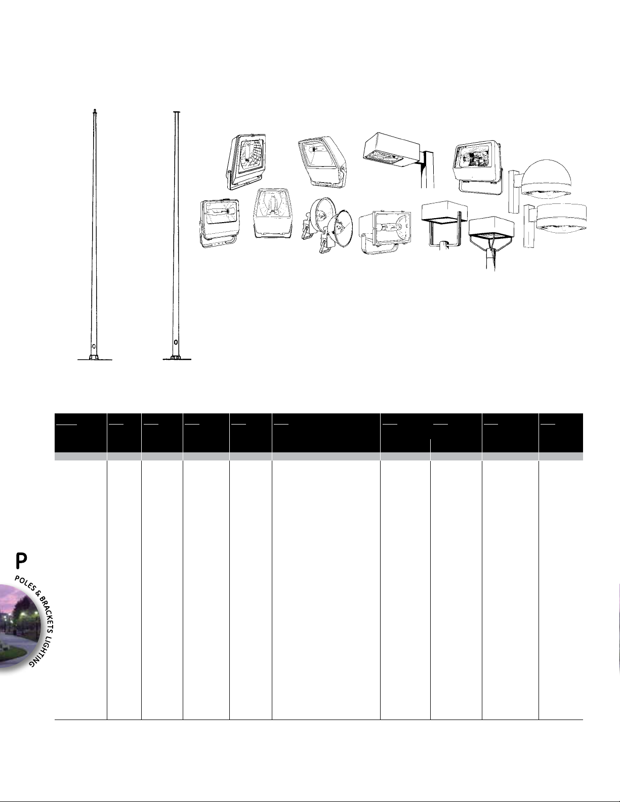
Aluminum ROunD TAPERED AREA liGHTinG POlES
20 TO 45 fEET (6 TO 14 mETERS)
SUGGESTED LUMINAIRE APPLICATIONS
PF4S,
HLUF
PF4T
DSMF, DSMT,
DSA
P54S
VLUF
PF1S,
PF1T
PSFA
SPECIFICATION FEATURES
• Round tapered seamless aluminum shaft
• Satin ground finish
• Shaft lengths from 20 to 45 feet
• Single or multiple luminaire mounting
• Two top tenon sizes
Pole with Top Tenon
(Mounting 2T & 4T)
Pole with Plate Top
Mount (Mounting PB)
• Plate mount for multiple-tenon bracket
• Black and dark bronze finishes available
ORDERING NUMBER LOGIC (See Pole Selection Table for actual Ordering Numbers)
A
PRODUCT IDENT
(LUMINAIRE
USAGE)
X
A = Area T = Tapered A = Aluminum 20 = 20
R
POLE
CROSS
SECTION
X
R = Round
T
SHAFT
SHAPE
X
A
POLE
MATERIAL
X
20
NOMINAL
MOUNTING
HEIGHT (FT)
XX
25 = 25
30 = 30
35 = 35
39 = 39
45 = 45
NOTE: 45
foot poles
have twopiece shafts
with ush
joint (eld
drilled and
bolted)
2T
MOUNTING
XX
2T = 2-3/8 in. OD top tenon
(See illustration above)
4T = 4 in. OD top tenon
(See illustration above)
DB = Drill holes for mounting two
Decashield® luminaires at 90°*
DO = Drill holes for two Decashield
luminaires at 180°*
PB = Plate and bracket mounting
for multiple luminaires
(See illustration above)
Order bracket separately
QD = Drill holes for four Decashield*
SD = Drill holes for single Decashield*
luminaire
TB = Drill holes for three Decashield
luminaires at 90°*
TD = Drill holes for three Decashield
luminaires at 120°*
*Requires pole vibration dampers
NOTE: Order round pole mounting
adapter separately.
NOTE: These mountings can be
used with any of the poles
listed; substitute the correct mounting designation
for XX in ordering number
listed in Selection Table.
NOTE: Drilling templates are the
same for Decashield®,
Dimension®, and DecasphereTM luminaires.
6.0
SHAFT DIMENSIONS
BOTTOM SHAFT
OD (IN.)
XXXX
6.0 = 6.0
7.0 = 7.0
8.0 = 8.0
10.0 = 10.0
DMY
B
WALL
THICKNESS (IN.)
X
B = 0.188
C = 0.219
D = 0.250
PF1K
DMS
DCD
SN
FINISH
XX
BL =
Black
DB = Dark bronze
SN= Satin
ground
(Standard)
NOTE: if black or
dark bronze nish is required,
substitute BL
or DB for SN in
ordering number
listed in Selection Table
DCF
E
OPTIONS
X
E = Electrical
Festoon
Box
NOTE: If this
option is
required, add
E to ordering
number
listed in Pole
Selection
Table.
P-6/2008
GE Lighting Solutions • 1-888-MY-GE-LED • www.gelightingsolutions.com
1 - 8 8 8 - 6 9 - 4 3 - 5 3 3
Page 2
Aluminum ROunD TAPERED AREA liGHTinG POlES
20 TO 45 fEET (6 TO 14 mETERS)
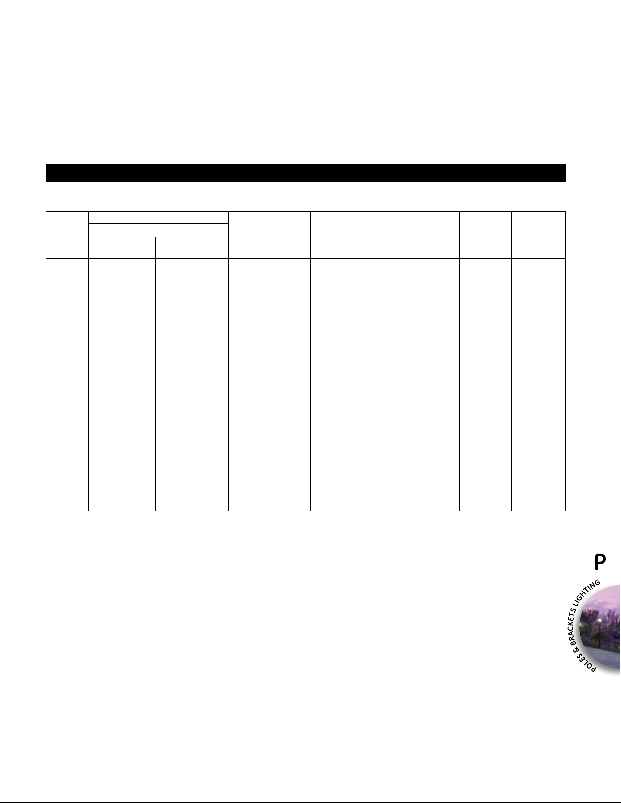
POLE SELECTION TABLE
Shipped with pole: anchor bolts, anchor bolt covers, handhole cover, hardware, and anchor bolt circle template.
Shaft cap included with poles drilled for Decashield® luminaire mounting.
Max Recommended Total Load
Nominal Approximate Data
Mounting Weight 80 90 100 Ordering Bottom OD X Top OD X Length X Thickness Weight Item
Height (ft) (lbs) MPHI MPHI MPHI Number (in. X in. X ft-in. X in.) (lbs) Number
20 230 7.9 6.3 5.1 ARTA20XX6.0BSN 6.0 X 4.0 X 19-8 X 0.188 80 43
20 280 11.7 9.2 7.4 20XX7.0BSN 7.0 X 4.0 X 19-8 X 0.188 90 44
25 165 5.6 4.4 3.4 25XX6.0BSN 6.0 X 4.0 X 24-8 X 0.188 100 43
25 225 8.6 6.7 5.3 25XX7.0BSN 7.0 X 4.0 X 24-8 X 0.188 105 44
25 285 12.2 9.4 7.5 25XX8.0BSN 8.0 X 4.0 X 24-8 X 0.188 125 45
25 330 14.4 11.2 8.9 25XX8.0CSN 8.0 X 4.0 X 24-8 X 0.219 140 45
25 370 16.6 12.9 10.3 25XX8.0DSN 8.0 X 4.0 X 24-8 X 0.250 145 45
30 165 6.4 4.9 3.7 30XX7.0BSN 7.0 X 4.0 X 29-8 X 0.188 130 44
30 190 9.3 7.2 5.6 30XX8.0BSN 8.0 X 4.0 X 29-8 X 0.188 135 45
30 220 11.2 8.7 6.8 30XX8.0CSN 8.0 X 4.0 X 29-8 X 0.219 155 45
30 250 13.0 10.1 8.0 30XX8.0DSN 8.0 X 4.0 X 29-8 X 0.250 170 45
30 425 16.4 12.3 9.2 30XX10.0BSN 10.0 X 6.0 X 29-8 X 0.188 185 46
30 490 19.4 14.7 11.1 30XX10.0CSN 10.0 X 6.0 X 29-8 X 0.219 210 46
30 560 22.4 17.0 13.0 30XX10.0DSN 10.0 X 6.0 X 29-8 X 0.250 235 46
30 680 28.0 21.5 16.6 30XX10.0ESN 10.0 X 6.0 X 29-8 X 0.312 300 46
35 160 6.2 4.7 3.6 35XX8.0BSN 8.0 X 4.0 X 34-8 X 0.188 160 45
35 180 7.6 5.9 4.5 35XX8.0CSN 8.0 X 4.0 X 34-8 X 0.219 185 45
35 205 9.1 7.0 5.6 35XX8.0DSN 8.0 X 4.0 X 34-8 X 0.250 215 45
35 258 11.7 8.7 6.3 35XX10.0BSN 10.0 X 6.0 X 34-8 X 0.188 220 46
35 345 13.8 10.4 7.7 35XX10.0CSN 10.0 X 6.0 X 34-8 X 0.219 240 46
35 390 16.1 12.2 9.2 35XX10.0DSN 10.0 X 6.0 X 34-8 X 0.250 285 46
39 170 7.1 5.4 4.0 39XX8.0DSN 8.0 X 4.0 X 38-9 X 0.250 240 45
39 250 9.3 6.6 4.5 39XX10.0BSN 10.0 X 6.0 X 38-9 X 0.188 250 46
39 285 11.2 8.1 5.7 39XX10.0CSN 10.0 X 6.0 X 38-9 X 0.219 285 46
39 325 13.2 9.7 7.0 39XX10.0DSN 10.0 X 6.0 X 38-9 X 0.250 320 46
45 265 9.1 6.3 3.7 45XX10.0CSN 10.0 X 6.0 X 44-8 X 0.219 315 46
45 300 10.8 7.7 4.8 45XX10.0DSN 10.0 X 6.0 X 44-8 X 0.250 415 46
Shaft DimensionsEective Projected Area (sq ft)
Pole Base
REFERENCES
See Pole Accessories for Bracket Ordering Information
See Area Accessories for Round Pole Mounting Adapter
See Page P-20 for Option Information
See Page P-21 for Pole Base Data
See Page P-2 for Pole Selection Guidelines
GE Lighting Solutions • 1-888-MY-GE-LED • www.gelightingsolutions.com
1 - 8 8 8 - 6 9 - 4 3 - 5 3 3
2008/P-7
 Loading...