

Page 1
g
GE Power Management
ALPS
Advanced Line Protection™ System
Instruction Manual
Firmware Revision: V0004.04AA34 (Rev. A models)
Firmware Revision: V0005.02AA05 (Rev. B models)
Manual P/N: GEK-105555F
Copyright © 2002 GE Power Management
Note: All relays must be powered up at least once per year to avoid
deterioration of electrolytic capacitors and subsequent relay failure.
GE Power Management
215 Anderson Avenue, Markham, Ontario
Canada L6E 1B3
Tel: (905) 294-6222 Fax: (905) 294-8512
Internet: http://www.GEindustrial.com/p m
Manufactured under an
ISO9002 Registered system.
Page 2

Page 3

These instructions do not purport to cover all details or variations in equipment nor provide for every possible contingency
to be met in connection with installation, operation, or maintenance. Should further information be desired or should particular problems arise which are not covered sufficiently for the purchaser’s purpose, the matter should be referred to the
General Electric Company.
To the extent required the products described herein meet applicable ANSI, IEEE, and NEMA standards; but no such
assurance is given with respect to local codes and ordinances because they vary greatly.
Page 4

Page 5

TABLE OF CONTENTS
1. PRODUCT DESCRIPTION
1.1 GETTING STARTED
1.1.1 INSPECTION ..................................................................................................... 1-1
1.1.2 PASSWORDS, FACTORY SET......................................................................... 1-1
1.1.3 REMOTE COMMUNICATIONS VIA LOCAL PC................................................1-2
1.1.4 ALPS-LINK QUICK REFERENCE ..................................................................... 1-2
1.1.5 ORDERING........................................................................................................ 1-3
1.2 INTRODUCTION
1.2.1 DESCRIPTION................................................................................................... 1-4
1.2.2 APPLICATION ................................................................................................... 1-4
1.2.3 PROTECTION FUNCTIONS..............................................................................1-4
1.2.4 GROUND DISTANCE QUADRILATERAL CHARACTERISTICS ...................... 1-5
1.2.5 LINE PROTECTION SCHEMES........................................................................ 1-8
1.3 CUSTOM PROGRAMMABILITY
1.3.1 INTRODUCTION................................................................................................1-9
1.3.2 PROGRAMMABLE LOGIC ................................................................................ 1-9
1.3.3 CONFIGURABL E INPUTS. ... ................... .................... ................... ... ................ 1-9
1.3.4 CONFIGURABL E OUTPUTS.. .................... ................... .................... .............. 1-10
1.4 AUXILIARY PROTECTION FUNCTIONS
1.4.1 POTENTIAL TRANSFORMER FUSE FAILURE (PTFF).................................1- 11
1.4.2 LINE PICKUP................................................................................................... 1-12
1.4.3 REMOTE-OPEN DETECTOR.......................................................................... 1-13
1.4.4 OUT-OF-STEP BLOCKING ............................................................................. 1-14
1.5 OTHER FEATURES
1.5.1 FLASH MEMORY ............................................................................................1-16
1.5.2 LINE OVERLOAD ............................................................................................ 1-16
1.5.3 CURRENT UNBALANCE DETECTION...........................................................1-16
1.5.4 FAULT LOCATION .......................................................................................... 1-16
1.5.5 FAULT REPORT.............................................................................................. 1-16
1.5.6 OSCILLOGRAPHY ..........................................................................................1-16
1.5.7 PLAYBACK ...................................................................................................... 1-17
1.5.8 SEQUENCE OF EVENTS..... .. .................... ................... .................... .............. 1-17
1.5.9 EQUIPMENT DUTY......................................................................................... 1-17
1.5.10 SELECTABLE GROUPS OF SETTINGS .................................... .................... 1-17
1.5.11 TIME SYNCHRONIZATION............................................................................ .1-18
1.5.12 TRIP BUS CHECK........................................................................................... 1-18
1.5.13 TRIP CIRCUIT MONITOR ........ .. ............................... ............................... .. .....1-18
1.5.14 ALARMS .......................................................................................................... 1-19
1.5.15 METERING ...................................................................................................... 1-19
1.5.16 BREAKER CONTROL ................................... ................... .................... ... ........ 1-19
1.6 COMMUNICATIONS
1.6.1 KEYPAD AND DISPL A Y. ... ................... .................... ................... ... ................. 1-20
1.6.2 SERIAL COMMUNICATIONS.......................................................................... 1-20
1.6.3 SCADA DIGITAL TO ANALOG (DTA) INTERFACE........................................ 1-20
1.7 SELF-TEST FEATURES
1.7.1 START-UP SELF-TESTS ................................................................................ 1-21
1.7.2 RUN-TIME SELF-TESTS..................................... ............................. .. .............1-21
1.7.3 CONTINUOUS MONITOR ............................................................................... 1-22
1.8 PROTECTION SCHEMES
1.8.1 INTRODUCTION..............................................................................................1-23
1.8.2 STEP DISTANCE............................................................................................. 1-23
1.8.3 PERMISSIVE UNDERREACH TRANSFER TRIP (PUTT)..............................1-25
1.8.4 PERMISSIVE OVERREACH TRANSFER TRIP (POTT1)............................... 1-27
1.8.5 POTT WITH BLOCKING FUNCTIONS (POTT2).............................................1-27
1.8.6 BLOCKING SCHEME ...................................................................................... 1-30
1.8.7 HYBRID SCHEME ........................................................................................... 1-33
1.8.8 SINGLE PHASE TRIPPING............................................................................. 1-35
1.9 PHASE IDENITIFIED CHANNEL SCHEMES
1.9.1 DESCRIPTION................................................................................................. 1-38
1.9.2 INTER-CIRCUIT FAULTS................................................................................1-38
1.9.3 TWO CHANNEL PHASE IDENTIFIED CHANNEL LOGIC ..............................1-38
1.9.4 FOUR CHANNEL PHASE IDENTIFIED CHANNEL LOGIC ............................ 1-40
GE Power Management
ALPS Advanced Line Protection System i
Page 6

TABLE OF CONTENTS
1.10 OUT-OF-STEP TRIPPING (OPTIONAL)
1.10.1 DESCRIPTION .................................................................................................1-41
1.10.2 OST CHARACTERISTIC SHAPE.....................................................................1-41
1.10.3 OUT-OF-STEP DETECTION............................................................................1-42
1.10.4 TWO-CHARACT E R IS TIC OP E R ATION........... ... ... ................... .................... ...1-43
1.10.5 OUT-OF-STEP OSCILLOGRAPHY CAPTURE................................................1-43
1.11 COMPENSATED POSITIVE SEQUENCE OVERVOLTAGE (OPTIONAL)
1.11.1 DESCRIPTION .................................................................................................1-44
1.11.2 APPLICATION ..................................................................................................1-44
1.12 RECLOSER (OPTIONAL)
1.12.1 DESCRIPTION .................................................................................................1-45
1.12.2 RECLOSING MODE.........................................................................................1-45
1.12.3 RECLOSING PROGRAMS...............................................................................1-45
1.12.4 RECLOSER INPU TS............................. ... .. .................... .................... ..............1 - 46
1.12.5 RECLOSER OUTP UT S............................................... .................... ................. 1 - 47
1.12.6 \SYNCHRONISM CHECK (OPTIONAL)...........................................................1-48
1.12.7 ALPS RECLOSING PROGRAM SUMMARY....................................................1-48
1.13 ELEMENTARY DIAGRAMS
1.13.1 ELEMENTARY DIAGRAMS .............................................................................1-49
2. CALCULATION OF
SETTINGS
2.1 INTRODUCTION
2.1.1 DESCRIPTION ...................................................................................................2-1
2.2 GENERAL SETTINGS
2.2.1 CONFIGURATION..............................................................................................2-2
2.2.2 COMMUNICATIONS ..........................................................................................2-4
2.2.3 OSCILLOGRAPHY.............................................................................................2-6
2.2.4 EQUIPMENT DUTY............................................................................................2-6
2.2.5 PROGRAMMABLE INPUTS...............................................................................2-8
2.3 PROTECTION SETTINGS
2.3.1 Z1DISTANCE .....................................................................................................2-9
2.3.2 ZONE 2, ZONE 3, AND ZONE 4 DISTANCE FUNCTIONS.............................2-13
2.3.3 Z2DISTANCE ...................................................................................................2-14
2.3.4 Z3DISTANCE ...................................................................................................2-16
2.3.5 Z4DISTANCE ...................................................................................................2-18
2.3.6 CURSUPVISN.......................................................................................... ........2-22
2.3.7 OVERCURRNT ........... .. ............................ .. .......................... .. .........................2-2 5
2.3.8 VOLTAGE.........................................................................................................2-27
2.3.9 POSITIVE-SEQUENCE VOLTAGE FUNCTIONS............................................2-28
2.3.10 BLK RECLOS ...................................................................................................2-29
2.3.11 LINEPICKUP ....................................................................................................2-30
2.3.12 REMOTEOPEN ................................................................................................2-31
2.3.13 LINEOVRLD .....................................................................................................2-32
2.3.14 SCHEME ..........................................................................................................2-32
2.3.15 SCHMTIMERS..................................................................................................2-33
2.3.16 LINE INFO ........................................................................................................2-36
2.3.17 SCADA DTA .....................................................................................................2-37
2.3.18 OS BLOCKING .................................................................................................2-38
2.3.19 OS TRIPPING...................................................................................................2-39
2.3.20 RECLOSER ......................................................................................................2-41
2.3.21 NONCRIT_AL ...................................................................................................2-46
2.3.22 OUTPUTS.........................................................................................................2-46
2.4 INVERSE CURVES
2.5 REFERENCE TABLES
2.5.1 INDEX NUMBERS............................................................................................2-51
2.5.2 PROTECTION SETTINGS GUIDE...................................................................2-57
2.5.3 GENERAL SETTINGS GUIDE .........................................................................2-64
2.5.4 PROTECTION SETTINGS DATA SHEETS .....................................................2-66
2.5.5 GENERAL SETTINGS DATA SHEETS............................................................2-73
ii ALPS Advanced Line Protection System
GE Power Management
Page 7

TABLE OF CONTENTS
3. HARDWARE DESCRIPTION
4. ACCEPTANCE/PERIODIC
TESTS
3.1 CASE ASSEMBLY
3.1.1 CONSTRUCTION .............................................................................................. 3-1
3.1.2 ELECTRICAL CONNECTIONS AND WIRING .................................................. 3-3
3.1.3 IDENTIFICATION...............................................................................................3-3
3.1.4 SYSTEM BLOCK DIAGRAM ............................................................................. 3-4
3.2 INSTALLATION
3.2.1 RECEIVING, HANDLING, AND STORAGE....................................................... 3-5
3.2.2 ENVIRONMENT................................................................................................. 3-5
3.2.3 MOUNTING........................................................................................................3-5
3.2.4 EXTERNAL CON N ECT I ONS......................... ................... .................... ............. 3-5
3.2.5 SURGE GROUND CONNECTIONS.................................................................. 3-5
3.3 PRINTED CIRCUIT BOARD MODULES
3.3.1 WARNING.......................................................................................................... 3-6
3.3.2 BASIC CONSTRUCTION..................................................................................3-6
3.3.3 MODULE IDENTIFICATION .............................................................................. 3-6
3.3.4 LOCAL USER INTERFACE (LUI)...................................................................... 3-6
3.3.5 INPUT BOARD............. ... ................... .................... .................... ................... ... .. 3-6
3.3.6 MAGNETICS MODULE .....................................................................................3-8
3.3.7 COMMUNICATIONS INTERFACE .................................................................... 3-9
3.3.8 DIGITAL OUTPUT / POWER SUPPLY BOARD.............................................. 3-10
3.3.9 DSP / ANI / COMM / LUI.................................................................................. 3-11
3.3.10 960 CPU BOARD............................................................................................. 3-12
4.1 OVERVIEW
4.1.1 INTRODUCTION................................................................................................4-1
4.1.2 TEST EQUIPMEN T......... ................... .................... .................... ................... ... .. 4-1
4.1.3 DRAWINGS AND R EF ER E NC E S ........... ... ................... .................... ................ 4-1
4.1.4 EQUIPMENT GROUNDING ............. .. ...............................................................4-2
4.1.5 REQUIRED SETTI N GS .......... ... ... ................... .................... .................... .......... 4-2
4.1.6 GENERAL INSTRUCTIONS .............................................................................. 4-2
4.1.7 SETTING CHANGE S............................... ... ................... .................... ................ 4-3
4.1.8 ENTERING TEST M OD E........ ... ... ................... .................... .................... .......... 4-4
4.1.9 USING COMMUNICATIONS (OPTIONAL)........................................................ 4-4
4.2 GENERAL RELAY TESTS
4.2.1 T1 – RELAY STATUS AND DISPLAY TESTING...............................................4-7
4.2.2 DISPLAY AND KEYPAD TESTS ....................................................................... 4-7
4.2.3 T2 – DIGITAL OUTPUT TEST ........................................................................... 4-8
4.2.4 T3 – CONFIGURABLE INPUT AND OUTPUT TEST ........................................ 4-9
4.2.5 T4 – AC SYSTEM INPUT TEST ...................................................................... 4-10
5. FUNCTIONAL TESTS
(FACTORY SETTINGS)
GE Power Management
5.1 TEST SUMMARY
5.1.1 DESCRIPTION................................................................................................... 5-1
5.2 MEASURING UNIT TESTS
5.2.1 T1 – FAULT DETECTOR TEST......................................................................... 5-2
5.2.2 T2 – IT TRIP SUPERVISION TEST................................................................... 5-2
5.2.3 T3 – IB BLOCKING SUPERVISION TEST ........................................................ 5-3
5.2.4 T4 – GROUND DIRECTIONAL TRIP TEST, IPT + NT...................................... 5-3
5.2.5 T5 – GROUND DIRECTIONAL BLOCK TEST, IPB + NB.................................. 5-3
5.2.6 T6 – PHASE INSTANTANEOUS OVERCURRENT 50 ........... ..........................5-4
5.2.7 T7 – GROUND INSTANTANEOUS OVERCURRENT 50G...............................5-4
5.2.8 T8 – GROUND TIME OVERCURRENT 51G.....................................................5-4
5.2.9 UNDERVOLTAGE TEST....................................................... ............................5-5
5.2.10 T9 – T10 – OVERVOLTAGE TEST ................................................................... 5-5
5.3 ZONE REACH AND TIMER TESTS
5.3.1 GENERAL ZONE REACH TESTING CONSIDERATIONS ............................... 5-8
5.3.2 T11 – ZONE 1 GROUND REACH, M1G GROUND FAULTS . ...........................5-8
5.3.3 T12 – ZONE 2 GROUND REACH, MTG GROUND FAULTS............................5-9
5.3.4 T13 – ZONE 3 GROUND REACH, M3G GROUND FAULTS . ...........................5-9
5.3.5 T14 - ZONE 4 GROUND REACH, M4G GROUND FAULTS...........................5-10
ALPS Advanced Line Protection System iii
Page 8

TABLE OF CONTENTS
5.3.6 T15 – GROUND (ZONE BACKUP) TIMER TESTS..........................................5-11
5.4 PHASE-TO-PHASE ZONE REACH TESTING
5.4.1 T16 – ZONE 1 PHASE REACH, M1 FAULTS ..................................................5-13
5.4.2 T17 – ZONE 2 PHASE REACH, M2 FAULTS ..................................................5-13
5.4.3 T18 – ZONE 3 PHASE REACH, M3 FAULTS ..................................................5-14
5.4.4 T19 – ZONE 4 PHASE REACH, M4 FAULTS ..................................................5-15
5.4.5 T20 – PHASE (ZONE BACK-UP) TIMER TESTS ............................................5-16
5.5 MOB TESTING
5.5.1 T21 – OUT-OF-STEP REACH, MOB................................................................5-19
5.5.2 ENDING FUNCTIONAL TESTS................................................. ......................5-19
6. FUNCTIONAL TESTS (USER
SETTINGS)
6.1 ALPS FUNCTIONAL TESTS
6.1.1 DESCRIPTION ...................................................................................................6-1
6.1.2 DRAWINGS AND R EF ER E NC E S .......................... .. .................... .................... ..6-2
6.1.3 GENERAL INSTRUCTIONS...............................................................................6-3
6.1.4 ENTERING TEST M OD E ........................... .................... .................... ................ 6- 3
6.1.5 USING ALPS-LINK (OPTIONAL) .......................................................................6-3
6.2 GENERAL RELAY TESTS
6.2.1 T1 – LUI RELAY STATUS ..................................................................................6-4
6.2.2 T2 – LUI DISPLAY TEST....................................................................................6-4
6.2.3 T3 – DIGITAL OUTPUT TEST............................................................................6-4
6.2.4 T4 – AC SYSTEM INPUT TEST .........................................................................6-5
6.3 MEASURING UNIT TESTS
6.3.1 WARNING ..........................................................................................................6-6
6.3.2 T5 – IT TRIP SUPERVISION TEST ...................................................................6-6
6.3.3 T6 – IB BLOCKING SUPERVISION TEST (BLOCKING SCHEMES) ................6-6
6.3.4 T7 – GROUND DIRECTIONAL TRIP TEST, IPT + NT.......................................6-6
6.3.5 T8 – GROUND DIRECTIONAL BLOCK TEST, IPB + NB ..................................6-7
6.4 BACKUP PROTECTION TESTS
6.4.1 T9 – PHASE INSTANTANEOUS OVERCURRENT 50......................................6-8
6.4.2 T10 – GROUND INSTANTANEOUS OVERCURRENT 50G..............................6-8
6.4.3 T11 – GROUND TIME OVERCURRENT 51G....................................................6-9
6.5 ZONE REACH TESTS
6.5.1 GENERAL CONSID E RATIONS .................................. .................... .................6 - 10
6.5.2 ZONE 1–4 PHASE-TO-GROUND CALCULATIONS........................................6-10
6.5.3 T12 – ZONE 1 GROUND REACH TEST, M1G GROUND FAULTS................6-12
6.5.4 T13 – ZONE 2 GROUND REACH, MTG GROUND FAULTS ..........................6-13
6.5.5 T14 – ZONE 3 GROUND REACH, M3G GROUND FAULTS...........................6-13
6.5.6 T15 – ZONE 4 GROUND REACH, M4G GROUND FAULTS...........................6-14
6.5.7 ZONE 1 TO 4 PHASE-PHASE REACH CALCULATIONS ...............................6-14
6.5.8 T16 – ZONE 1 PHASE REACH, M1 FAULTS ..................................................6-16
6.5.9 T17 – ZONE 2 PHASE REACH, MT FAULTS..................................................6-16
6.5.10 T18 – ZONE 3 PHASE REACH, M3 FAULTS..................................................6-17
6.5.11 T19 – ZONE 4 PHASE REACH, M4 FAULTS..................................................6-17
6.5.12 ENDING FUNCTIONAL TESTS (USER SETTINGS).......................................6-17
7. SPECIFICATIONS
8. LOCAL USER INTERFACE
7.1 ALPS SPECIFICATIONS
7.1.1 DESCRIPTION ...................................................................................................7-1
8.1 INTRODUCTION
8.1.1 DESCRIPTION ...................................................................................................8-1
8.1.2 DISPLAY AND KEYPAD ....................................................................................8-1
8.1.3 CONTROL KEYS................................................................................................8-2
8.1.4 MESSAGES........................................................................................................8-3
8.1.5 SETTINGS..........................................................................................................8-4
8.1.6 EDIT PROTECTION SETTINGS ........................................................................8-4
8.1.7 [END] KEY ............................ .................... ................... .................... ...................8-6
iv ALPS Advanced Line Protection System
GE Power Management
Page 9

TABLE OF CONTENTS
8.1.8 EDIT GENERAL SETTINGS.............................................................................. 8-7
8.1.9 SELECT ACTIVE SETT GRP ............................................................................ 8-7
8.1.10 MODIFY DATE/TIME......................................................................................... 8-7
8.1.11 ACTIONS ........................................................................................................... 8-8
8.1.12 DISABLE OUTPUTS.......................................................................................... 8-8
8.1.13 ENABLE OUTPUT S................... .................... ................... .................... ............. 8-9
8.1.14 TRIP BREAKER................................................................................................. 8-9
8.1.15 CLOSE BREAKER............................................................................................. 8-9
8.1.16 RELAY TEST ................................................................................................... 8-10
8.1.17 CHANNEL TEST.. ... .. .................... ... ................... .................... ................... ...... 8-11
8.1.18 KEYPAD/DISPL AY INTERFACE TEST................................................ ........... 8-12
8.1.19 DIGITAL OUTPUT TEST ................................................................................. 8-12
8.1.20 PLAYBACK ...................................................................................................... 8-13
8.1.21 CHANGE PASSWORD....................................................................................8-14
8.1.22 ENABLE/DISABLE PASSWORDS .. .. ... .................... ................... .................... 8-15
8.1.23 RESET DATA................................................................................................... 8-15
8.1.24 RESET RECLOSER ........................................................................................8-15
8.1.25 ADJUST CONTRAST ...................................................................................... 8-15
8.2 INFORMATION
8.2.1 DESCRIPTION................................................................................................. 8-16
8.2.2 REQUEST STATUS INFORMATION .............................................................. 8-16
8.2.3 REQUEST FAULT INFORMATION .................................................................8-17
8.2.4 REQUEST PRESENT VALUES....................................................................... 8-18
8.2.5 CONTACT CONVERTER STATUS................................................................. 8-18
8.2.6 DIGITAL OUTPUT STATUS ............................................................................ 8-18
8.2.7 EVENT INFORMATION................................................................................... 8-19
8.2.8 COMMUNICATION PASSWORDS.................................................................. 8-21
8.2.9 REQUEST STATION/LINE ID.......................................................................... 8-21
8.2.10 REQUEST ALPS MODEL/VERSION............................................................... 8-21
8.2.11 OSCILLOGRA PHY SNAPSHOT.............. ... ................... .................... .............. 8-22
8.3 ASCII INTERFACE
8.3.1 DESCRIPTION................................................................................................. 8-23
8.3.2 RECOMMENDED REMOTE COMMUNICATIONS PACKAGE....................... 8-23
8.4 REMOTE COMMUNICATION INTERFACE
8.4.1 HARDWARE SWITCHES ................................................................................ 8-24
8.4.2 MODEM CONNECTIONS AND SETTINGS .................................................... 8-24
8.4.3 PC MODEM ..................................................................................................... 8-25
8.4.4 ALPS MODEM ................ ... ... ................... .................... ................... ................. 8-25
8.4.5 NULL-MODEM CONNECTIONS ..................................................................... 8-27
9. SERVICING
10. ALPS TEST PROGRAM
GE Power Management
9.1 SPARES
9.1.1 DESCRIPTION................................................................................................... 9-1
9.1.2 SERVICING WITH THE RELAY SELF-TEST.................................................... 9-1
9.2 TROUBLESHOOTING
9.2.1 DESCRIPTION................................................................................................... 9-3
9.2.2 THE INFORMATION STATUS COMMAND....................................................... 9-3
9.2.3 SERVICING A CRITICAL FAILURE .................................................................. 9-3
9.2.4 LOCATING THE DEFECTIVE BOARD.............................................................. 9-4
9.2.5 SERVICING A NON-CRITICAL FAILURE ......................................................... 9-4
9.2.6 LOCATING THE DEFECTIVE BOARD.............................................................. 9-4
9.2.7 SERVICE SYSTEM STATUS FAILURES.......................................................... 9-5
10.1 INTRODUCTION
10.1.1 DESCRIPTION................................................................................................. 10-1
10.1.2 STARTING PROGRAM AFTER THE FIRST TIME ......................................... 10-1
10.2 TEST CALCULATIONS
10.2.1 DESCRIPTION................................................................................................. 10-2
10.2.2 ENTERING INPUT QUANTITIES.................................................................... 10-2
10.2.3 ENTERING A VALU E ...................... ................... .................... ................... ... ... 10-3
10.2.4 SELECTING A VALUE..................................................................................... 10-3
ALPS Advanced Line Protection System v
Page 10

TABLE OF CONTENTS
10.2.5 M1 PHASE UNITS – ZONE 1...........................................................................10-3
10.2.6 MT PHASE UNITS – ZONE 2...........................................................................10-4
10.2.7 M3 PHASE UNITS – ZONE 3...........................................................................10-4
10.2.8 M4 PHASE UNITS – ZONE 4...........................................................................10-5
10.2.9 MOB PHASE UNIT...........................................................................................10-5
10.2.10 MIG GROUND UNITS – ZONE 1 .....................................................................10-6
10.2.11 MTG GROUND UNITS – ZONE 2...................................... ..............................10-6
10.2.12 M3G GROUND UNITS – ZONE 3 ................................................. ...................10-7
10.2.13 M4G GROUND UNITS – ZONE 4 ................................................. ...................10-7
10.3 FILE MENU
10.3.1 NEW TEST FILE...............................................................................................10-8
10.3.2 OPEN TEST FILE.............................................................................................10-8
10.3.3 OPEN SETTING FILE ......................................................................................10-8
10.3.4 CLOSE TEST FILE...........................................................................................10-9
10.3.5 SAVE INPUT QUANTITIES..............................................................................10-9
10.3.6 SAVE INPUT QUANTITIES AS ......................................................................10-10
10.3.7 SAVE OUTPUT AS.......... .. ... .................... ................... .................... ...............1 0 - 10
10.3.8 PRINT................................ .................... ................... .................... ... ...............1 0 - 10
10.3.9 PRINT SETUP ........ ... .................... ................... .................... ................... .......10-10
10.3.10 LAST 4 OPENED SETTINGS FILES..............................................................10-10
10.3.11 EXIT................................................................................................................10-10
10.4 EDIT MENU
10.4.1 COPY..............................................................................................................10-11
10.4.2 COPY TEXT ONLY.........................................................................................10-11
10.4.3 COPY MHO CIRCLE ONLY ...........................................................................10-11
10.5 VIEW MENU
10.5.1 DESCRIPTION ...............................................................................................10-12
10.5.2 TOOLBAR.......................................................................................................10-12
10.5.3 STATUS BAR ............ ... ................... .................... ................... .................... ....10-12
10.6 TOOLS MENU
10.6.1 DESCRIPTION .......... .................... .................................... .............................10-13
10.7 WINDOW MENU
10.7.1 DESCRIPTION ...............................................................................................10-15
10.7.2 CASCADE ......................................................................................................10-15
10.7.3 TILE ................................................................................................................10-15
10.7.4 ARRANGE ICONS..........................................................................................10-15
10.7.5 VIEWING MULTIPLE TESTS .........................................................................10-15
10.8 HELP MENU
10.8.1 CONTENTS ....................................................................................................10-16
10.8.2 ABOUT ALPS_TST ........................................................................................10-16
11. ALPS-LINK USER GUIDE
11.1 INSTALLATION
11.1.1 OVERVIEW ......................................................................................................11-1
11.1.2 USING ON-LINE HELP ....................................................................................11-1
11.1.3 SUPPORTED ARCHITECTURE .............. ................... .................... ... ..............1 1- 1
11.1.4 HARDWARE INSTALLATION ..........................................................................11-1
11.1.5 SOFTWARE INSTALLATION...........................................................................11-3
11.2 USING ALPS-LINK
11.2.1 STARTUP .........................................................................................................11-5
11.2.2 MENU BAR.......................................................................................................11-5
11.2.3 TOOLBAR.........................................................................................................11-5
11.2.4 STATUS BAR ............ ... ................... .................... ................... .................... ... ...11-5
11.3 SETTING UP YOUR HOST MACHINE
11.3.1 DESCRIPTION .................................................................................................11-6
11.3.2 COM PORT SETUP .........................................................................................11-6
11.3.3 MODEM SETUP ........ .................... .. .................... ................... .................... ......11-6
11.3.4 PRINTER SETUP.............................................................................................11-7
11.3.5 DEVICE SETUP .. ... ... .................... ................... .................... ................... .........11-7
11.3.6 ADDING A DEVICE..........................................................................................11-7
vi ALPS Advanced Line Protection System
GE Power Management
Page 11

TABLE OF CONTENTS
11.4 CONNECTING TO AND LOGGING OUT OF A DEVICE
11.4.1 DESCRIPTION................................................................................................. 11-9
11.4.2 CONNECT TO A DEVICE................................................................................ 11-9
11.4.3 LOGOUT FROM A DEVICE............................................................................. 11-9
11.5 SETTINGS AND ACTIONS
11.5.1 SETTINGS ..................................................................................................... 11-10
11.5.2 ACTIONS ....................................................................................................... 11-12
11.6 INFORMATION
11.6.1 DESCRIPTION............................................................................................... 11-14
11.6.2 OPEN REPORT ............................................................................................. 11-14
11.6.3 NEW REPORT............................................................................................... 11-14
11.6.4 FAULT REPORT............................................................................................ 11-15
11.6.5 OSCILLOGRA PHY REPORT .......... .. .................... .................... ................... . 11-15
11.6.6 BREAKER HEALTH REPORT....................................................................... 11-15
11.6.7 DEMAND REPORT...... ... ... ................... ... .................... ................... ............... 11- 15
11.6.8 DIAGNOSTICS REPORT .............................................................................. 11-15
11.6.9 EVENT REPORT ........................................................................................... 11-15
11.6.10 PRESENT VALUES REPORT.......................................................................11-15
11.6.11 STAT U S R EP ORT.... ... ... ... ................... .................... ................... .................. 1 1 - 15
11.6.12 CONTACT STATUS REPORT.......................................................................11-16
11.6.13 LUI PASSWORD REPORT............................................................................11-16
11.6.14 OPEN REPORT ............................................................................................. 11-16
11.6.15 SAV E RE PORT....... .. .................... ................... .................... .................... ...... 11-16
11.6.16 PRIN T R EP ORT .. ... ................... .................... ................... .................... ......... 11-16
11.7 LOGGING
11.7.1 SESSION LOG............. ... ... ................... ... .................... ................... ............... 11 - 17
11.7.2 TURN OFF.....................................................................................................11-17
11.7.3 CURRENT SESSION LOG..................... .. ............................ .........................11-17
11.7.4 OPEN SESSION LOG ................................................................................... 11-17
11.7.5 ARCHIVAL ..................................................................................................... 11-17
11.7.6 ARCHIVE ....................................................................................................... 11-17
11.7.7 RETREIVE ..................................................................................................... 11-18
12. ASCII COMMUNICATIONS
13. XPRESSION BUILDER
14. ALPS-SET PC SOFTWARE
12.1 INTRODUCTION
12.1.1 DESCRIPTION................................................................................................. 12-1
12.1.2 ASCII INTERFACE .......................................................................................... 12-1
13.1 INTRODUCTION
13.1.1 OVERVIEW...................................................................................................... 13-1
13.1.2 INSTALLATION................................................................................................ 13-1
13.1.3 DESIGN CONSIDE R A TIO N S ....... ................... .................... .................... ........ 13-1
13.1.4 BOOLEAN OPERATORS, LATCHES, TIMERS, & COUNTERS .................... 13-2
13.2 XPRESSION BUILDER FLAGS
13.2.1 CONTACT CONVERTER INPUTS.................................................................. 13-4
13.2.2 INPUT/OUTPUT FLA G S. ... ................... .................... ... ................... ................. 1 3- 4
13.3 CREATING XPRESSION BUILDER LOGIC
13.3.1 DESCRIPTION................................................................................................. 13-9
13.3.2 COMPILING AND DOWNLOADING XPRESSION BUILDER LOGIC...........13-11
13.3.3 BREAKER FAILU R E EX A M PL E.................................................. .................. 1 3 - 11
14.1 INTRODUCTION
14.1.1 INSTALLATION................................................................................................ 14-1
14.1.2 STARTING THE PROGRAM ........................................................................... 14-1
14.1.3 PRINT SETTINGS REPORT ........................................................................... 14-3
14.1.4 EDIT MENU – COPY SETTINGS REPORT .................................................... 14-3
14.1.5 TOOLS MENU .................................................................................................14-3
14.1.6 HELP MENU .................................................................................................... 14-4
GE Power Management
ALPS Advanced Line Protection System vii
Page 12

TABLE OF CONTENTS
A. FREQUENTLY ASKED
QUESTIONS
B. MODBUS
C. DNP
A.1 FREQUENTLY ASKED QUESTIONS
B.1 MODBUS INTRODUCTION
B.1.1 DESCRIPTION..................................................................................................B-1
B.1.2 COMMUNICATIONS SETTINGS......................................................................B-1
B.1.3 SUPPORTED MODBUS FUNCTIONS..............................................................B-1
B.1.4 EXCEPTION OR ERROR REPLIES.................................................................B-2
B.1.5 DATA FORMATS...............................................................................................B-2
B.2 REGISTER MAPS
B.2.1 SUMMARY........................................................................................................B-3
B.2.2 MODBUS MEMORY MAP.................................................................................B-5
B.2.3 MEMORY MAP DATA FORMATS...................................................................B-15
C.1 OVERVIEW
C.1.1 DESCRIPTION..................................................................................................C-1
C.1.2 MODIFYING SETTINGS USING DNP...............................................................C-1
C.2 DEVICE PROFILE
C.2.1 DNP V3.00 DEVICE PROFILE DOCUMENT....................................................C-2
C.2.2 IMPLEMENTATION TABLE..............................................................................C-4
C.2.3 IMPLEMENTATION TABLE NOTES.................................................................C-5
C.2.4 DEFAULT VARIATIONS....................................................................................C-5
C.3 POINT LISTS
C.3.1 DESCRIPTION..................................................................................................C-6
C.3.2 BINARY INPUT, BINARY INPUT CHANGE......................................................C-6
C.3.3 BINARY OUTPUT, CONTROL RELAY OUTPUT BLOCK..............................C-11
C.3.4 BINARY COUNTER, FROZEN COUNTER.....................................................C-12
C.3.5 ANALOG INPUT, ANALOG INPUT CHANGE.................................................C-13
C.3.6 ANALOG OUTPUT, ANALOG OUTPUT BLOCK............................................C-19
C.3.7 DATA FORMATS – ANALOG INPUT AND OUTPUT POINTS.......................C-26
D. KEYPAD MENUS
E. FIGURES AND TABLES
F. WARRANTY
INDEX
D.1 KEYPAD MENUS
D.1.1 SET KEYPAD MENU.........................................................................................D-1
D.1.2 ACT KEYPAD MENU........................................................................................D-2
D.1.3 INF KEYPAD MENU..........................................................................................D-3
E.1 FIGURES AND TABLES
E.1.1 LIST OF FIGURES............................................................................................E-1
E.1.2 LIST OF TABLES..............................................................................................E-3
F.1 WARRANTY INFORMATION
F.1.1 GE POWER MANAGEMENT WARRANTY.......................................................F-1
INDEX
viii ALPS Advanced Line Protection System
GE Power Management
Page 13

1 PRODUCT DESCRIPTION 1.1 GETTING STARTED
1 PRODUCT DESCRIPTION 1.1 GETTING STARTED 1.1.1 INSPECTION
Before attempting to install or use this relay, it is imperative that all WARNINGS and CAUTIONS in this ma nual are reviewed to help prevent personal injury, equipment damage, and/or downtime.
NOTE
Unpack the relay, the mounting brackets, and the hardware for attaching the mounting brackets to the sides of the relay.
Examine the rela y for an y dam age sustained in t rans it , and if damage is ev id ent, no tify the shipping c om pa ny an d the nearest GE Power Management sales office immediately.
Prior to applying power, ensure that the model number of the relay listed on the front panel corresponds to the model
ordered. Make sure that the DC supply power matches the rated voltage listed on the front panel. Refer to the elementary
diagrams on pages 1–49 to 1–52 for the locations of the DC power inputs
Instructi ons o n using the keypad to c hange s etti ngs an d put t he rel ay in to te st mode can b e fo und in Secti on 4.1 .7: SE TTING CHANGES on page 4–3. Complete instructions on operating the keypad are found in Chapter 8: LOCAL USER
INTERFACE.
GE Power Management contact information:
GE Power Management
215 Anderson Avenue
Markham, Ontario
Canada L6E 1B3
Telephone: Toll Free North America: (800) 547-8629
Europe +34 94 485 88 54
Other Areas (905) 294-6222
Emergency (416) 414-4941
Fax: (905) 201-2098
Email: info.pm@indsys.ge.com
Home Page: www.GEindustrial.com/pm
1
1.1.2 PASSWORDS, FACTORY SET
The ALPS requires passwords to change settings or perform actions. No password is required to obtain information from
the relay, including viewing the existing settings. The relay is shipped from the factory with the following MMI passwords:
SETTINGS: 123.
ACTIONS: 456.
MASTER: 789.
The decimal point following the digits is part of the password. Factory passwords MUST be changed
before the user can modify settings or initiate Actions.
NOTE
In order to change the default password, follow these steps:
1. Press the ACTIONS key [ACT].
2. Press the ENTER key [ENT].
3. Scroll to the CHANGE PASSWORD option.
4. Select the Password Privilege level to be changed.
5. Press [ENT].
6. Enter the factory password (for example: 789. for Master Password).
7. Enter your password.
8. Re-enter your password.
9. Press [END], press [ENT], and then press [CLR].
The keypad passwords stored in the relay may be viewed, in encoded format, via remote communications.
GE Power Management
ALPS Advanced Line Protection System 1-1
Page 14

1.1 GETTING STARTED 1 PRODUCT DESCRIPTION
1.1.3 REMOTE COMMUNICATIONS VIA LOCAL PC
1
To communicate with the relay through a PC, connect the relay to a serial port of an IBM-compatible computer with a
null-modem cable. Connection can be made either to the 25 pin D-connector on the back of the relay (PL2A), or the 9 pin
D-connector on the front (PL1). Cable diagrams are shown in the following:
• Figure 8–2: MODEM CABLE on page 8–23
• Figure 8–3: 25-PIN NULL MODEM CABLE on page 8–23
• Figure 8–4: 25-PIN NULL MODEM CABLE on page 8–27
• Figure 8–5: NULL MODEM CABLE FOR PORT PL1 on page 8–27
The communications software required to access the relay, ALPS-Link, is included on the enclosed Products CD. Follow
instructions in Section 11.1.5 SOFTWARE INSTALLATION on page 11–3 to load ALPS-Link onto the PC.
1.1.4 ALPS-LINK QUICK REFERENCE
The ALPS relay requires the use of passwords to obtain information from the relay, to change Settings, or to perform
Actions. The relay is shipped from the factory with the following communications passwords:
VIEW: VIEW!
SETTINGS: SETTING!
ACTIONS: CONTROL!
MASTER: MASTER!
The exclamation point following the letters is part of the factory password. The factory passwords MUST
be changed before the user can modify Settings or initiate Actions. The user can log into the relay at any
NOTE
password level. After logging into the relay, the password can be changed under the ACTION menu by
selecting CHANGE PASSWORD.
The user must logout from the ALPS before changing another password. The remaining passwords can then be changed
by logging into the ALPS using another default password. The communications passwords may be viewed, in an encoded
format, via the [INF] (information) key.
To log into the relay, follow the instructions in Section 4.1.9: USING COMMUNICATIONS (OPTIONAL) on page 4–4. Any
one of the factory passwords can be used to log on to the relay. The relay UNITID (General Setting 101) is factory set to
"0".
1-2 ALPS Advanced Line Protection System
GE Power Management
Page 15

1 PRODUCT DESCRIPTION 1.1 GETTING STARTED
1.1.5 ORDERING
Table 1–1: ORDER CODES
ALPS * * * * * * * * * * * * – *
Base Unit
Distance Relay
Revision
Tripping Logic
Current Rating
Series
Capacitors
Battery
Voltage
Trip Outputs
Comm Ports
Mounting
Oscillography
ALPS
|||||||||||| |
D
| | | | | | | | | | | |
A
|||||||||| |
B
|||||||||| |
1
| | | | | | | | | |
3
| | | | | | | | | |
1
|||||||| |
5
|||||||| |
U
| | | | | | | |
C
| | | | | | | |
0
|||||| |
1
|||||| |
2
|||||| |
1
| | | | | |
2
| | | | | |
3
| | | | | |
4
| | | | | |
2
|||| |
3
|||| |
H
| | | |
V
| | | |
S
E
OST / Positive
Sequence
Overvoltage
Recloser
Protocol
† These options are applicable to Revision A models only.
|| |
|| |
0
| |
1
| |
2
| |
3
| |
N
R
S
Base Unit
Distance Relay
ALPS Revision A
ALPS Revision B
Single Phase Tripping Logic
Three Phase Tripping Logic
1 Ampere rated current
5 Ampere rated current
For applications without series capacitors
For Applications with series capacitors
48V DC battery voltage
110/125 V DC battery voltage
220/250 V DC battery voltage
SCR trip outputs & contact channel interface
Contact trip outputs & contact channel interface
SCR trip outputs & 5V / 20mA channel interface
Contact trip outputs & 5V / 20 mA channel interface
Front RS232 port & 1 settable RS232/RS485 rear port (GEmodem/ASCII)
Front RS232 port & 2 settable RS232/RS485 rear ports (GEmodem/ASCII)
Horizontal mounting
Vertical mounting
Standard oscillography memory
Extended oscillography memory
No out-of-step tripping or positive sequence overvoltage
With out-of-step tripping
With positive sequence overvoltage units
With positive sequence overvoltage units & out-of-step tripping
No recloser
|
Recloser
|
Recloser with sync check
|
AC
Modbus RTU communication
†
†
†
†
†
EXAMPLE: ALPSDA35U122VE1N = ALPS Digital Line Protection Distance Relay; revision A; three phase tripping logic;
rated at 5 amperes; without series capacitor protection; 110/125 VDC supply; contact tripping outputs; 2 communications
ports; vertical mounting; with extended memory; without OST functions; and no recloser.
1
†
GE Power Management
ALPS Advanced Line Protection System 1-3
Page 16

1.2 INTRODUCTION 1 PRODUCT DESCRIPTION
1.2 INTRODUCTION 1.2.1 DESCRIPTION
1
The Advanced Line Protection System (ALPS) is a microprocessor-based digital relay system that uses waveform sampling with appropriate algorithms to provide three phase or single phase tripping schemes for transmission line protection,
fault location, and related features. The models covered by this instruction book are intended for either three phase or single phase tripping applications. The relay samples the current and voltage inputs from the power system 64 times per
cycle. Protection algorithms process this sampled data in sets of four, sixteen times per cycle. The ALPS uses advanced
Fourier calculation techniques and adaptive measuring functions to achieve high-speed tripping for severe faults.
The ALPS is packaged in a compact 3 Rack Unit high (one RU = 1.75 Inches) 19-in ch rack moun t cas e and is ava il abl e for
either horizontal or vertical mounting. The case outline and mounting dimensions are shown in Figure 3–2: FRONT AND
REAR VIEW on page 3–2.
All models include a f ull ke yp ad a nd a liquid crystal displa y (LCD ) for local access to re lay da ta an d s etti ngs . In add iti on, up
to three communicatio n po rts are pro vided for both l ocal and rem ote ac cess with a PC. Each port may be indepe ndentl y set
for ASCII or GEmodem protocols.
1.2.2 APPLICATION
The models covered by this instruction book are designed to be used on transmission lines of any voltage level, with or
without series capacitor compensation, where either single or three-phase tripping is required. Detailed application considerations are described in this chapter and in Chapter 2: CALCULATION OF SETTINGS.
The ALPS can provide high speed detection and clearing of power system faults, and includes logic for step distance and
five standard pilot tripping schemes. The scheme logic is described in Section 1.8: PROTECTION SCHEMES on page 1–
23. The external connections for the ALPS are shown in the elementary diagrams on pages 1–49 to 1–52.
The ALPS is available with either a contact interface to the pilot channel equipment or an electronic (5 V, 20 mA) interface
so that the relay may b e appl ied with a wi de vari ety of chann el equ ipmen t. Typical cha nnels incl ude: AM and FSK via po wer
line carrier (PLC), FSK via microwave, and multiplexed fiber optic cable.
1.2.3 PROTECTION FUNCTIONS
The measurement functions are listed in Table 1–2: ALPS MEASUREMENT FUNCTIONS on page 1–5.
The Zone 1 distance functions provide secure high-speed tripping for all fault types over most of the protected line. The
Zone 1 ground distance functions can be selected to be either ground variable-Mho distance functions, or ground-reactance distance functions. The ALPS also offers ground quadrilateral distance functions as Zone 1 ground distance functions. A unique adaptive reach for the supervising Mho characteristic is used when ground-reactance functions are
selected.
Overreaching Zone 2 p has e and ground distance func tio ns are us ed fo r pi lot tripping schemes. G ro und -directional overcurrent functions can be selected to replace or supplement the overreaching zone (Zone 2) ground-distance functions in any
of the pilot schemes. The ALPS also offers Zone 2 ground quadrilateral characteristics. The Zone 2 phase and ground distance functions are provided with independent timers for time delayed backup protection.
Overreaching Zone 3 phase and ground distance functions are provided with independent timers for time delayed backup
protection. The ALPS also has the option for quadrilateral ground-distance functions.
The Zone 4 variable-Mho distance functions can be reversed in direction when a reversed or blocking function is required.
When the POTT 2, Blocking or H ybrid scheme i s selected, Zon e 4 is automatic ally set to the rev erse directi on, because
these schemes require a reverse-looking blocking function. The Zone 4 phase and ground distance functions are provided
with independent timers for time delayed backup protection. The ALPS with three phase tripping also has the option to use
Zone 4 ground quadrilateral distance functions for time-delayed backup protection.
When both phase and ground distance functions are used for a zone of protection, six individual measuring functions are
available: three fo r pha se dis tan ce and thre e for ground distance. The alg orit hm that im ple me nts the variable-Mho measuring functions is derived from designs that have evolved through several different families of static analog and digital relay
systems which have accumulated decades of dependable and secure in-service experience.
An instantaneous overcurrent tripping function (50G) provides direct tripping for severe phase-to-ground faults. Time-overcurrent tripping (51G) provides time-delayed backup tripping for phase-to-ground faults. Either or both of these groundovercurrent functions can be controlled by the NT negative-sequence directional trip unit, at the customer’s discretion.
1-4 ALPS Advanced Line Protection System
GE Power Management
Page 17

1 PRODUCT DESCRIPTION 1.2 INTRODUCTION
Table 1–2: ALPS MEASUREMENT FUNCTIONS
ZONE OR TYPE FUNCTIONS
Zone 1 • 3 Variable-Mho phase-distance functions
• 3 Variable-Mho ground-distance functions
• 3 Reactance ground-distance functions with “adaptive reach” Mho supervision
3 Quadrilateral ground-distance functions (Revision B relays only).
Zone 2 (Pilot Zone) • 3 Variable-Mho phase distance functions
3 Variable Mho ground-distance functions
Ground directional-overcurrent functions consisting of:
IPT: Ground Trip overcurrent
NT: Negative Sequence Directional Trip
IPB: Ground Block overcurrent
NB: Negative Sequence directional block
or
3 Quadrilateral ground-distance functions (Revision B relays only)
Zone 3 • 3 Variable-Mho phase-distance functions
• 3 Variable-Mho ground-distance functions,
3 Quadrilateral ground-distance functions (Revision B relays only)
Zone 4 • 3 Reversible variable-Mho phase-distance functions
• 3 Reversible variable-Mho ground-distance functions,
3 Quadrilateral ground-distance functions (Revision B relays only)
Out of Step Blocking (OSB) • 3 Variable-Mho phase-distance functions
Overcurrent Backup • 50: Phase-overcurrent direct trip (directional or nondirectional
• 50G: Ground-overcurrent direct trip (directional or nondirectional)
• 51G: Ground time-overcurrent direct trip (directional or nondirectional)
Overcurrent Supervision • IT: Trip-supervision overcurrent
• IB: Block-supervision overcurrent
Fault Detector • FD
Line-Pickup Overcurrent • I1
Remote-Open Detectors • ROD
Line-Overload Detectors • Level 1 Overcurrent
• Level 2 Overcurrent
Phase Undervoltage • Three fixed pickup phase undervoltage detectors
Phase Over / Undervoltage • T hree adjustable over or under voltage detectors with time delay
Positive-Sequence Voltage
Detectors
Out of Step Tripping (OST) • 3 Variable-Mho positive sequence-distance functions
•V1,
• V1 compensated
and/or
or
or
or
1
1.2.4 GROUND DISTANCE QUADRILATERAL CHA RACTERISTICS
The ALPS relay has been modified to include the option to use either quadrilateral characteristics or variable Mho characteristics for all zones of ground distance protection. The model numbers affected by this modification are: ALPSDB
XXXXXXXXX
(where X may be any valid character) with firmware version V0005.00AA00 or higher. A new version of
ALPS-Link may be required to access the new settings via remote communications (ALPS-Link must be version 3.5 or
higher). If required, the updated version of ALPS-Link may be downloaded from the GE power Management website at
www.GEindustrial.com/pm
.
Many protective re la y engineers prefer to us e a qua dri late r al (p oly gon al ) c hara ct eris tic f or grou nd di stance functions to p rovide more fault resistance coverage than the circular mho characteristic. A typical quadrilateral characteristic is shown in
Figure 1–1: GROUND DISTANCE QUADRILATERAL CHARACTERISTIC. The characteristic is comprised of four straight
lines; the trip zone is the inside area bounded by all four characteristics. The upper boundary, the reactance characteristic,
may also be used with a variable mho function. The variable mho provides both directional supervision for reverse faults.
and resistive limits to prevent operation on load.
GE Power Management
ALPS Advanced Line Protection System 1-5
Page 18

1.2 INTRODUCTION 1 PRODUCT DESCRIPTION
1
X
1
4
3
R
2
Figure 1–1: GROUND DISTANCE QUADRILATERAL CHARACTERISTIC
In the ALPS r el ay t he fo ur strai ght line s of th e qu adri lat eral cha rac teri sti c are deve lop ed b y a combin ati on of th e fo llo wing
three characteristics:
1. Reactance characteristic (section 1). The tilt of the reactance characteristic is determined by the characteristic timer
setting. The range of the setting is 80° to 155° in 1° steps.
2. Restricted directional characteristic (sections 2 and 4)
3. Ri ght (pos iti ve ) resist ive bli nder (section 3)
The following definitions pertain to all of the distance functions:
I
= phase A current at relay
A
I
= phase B current at relay
B
I
= phase C current at relay
C
I
= zero-sequence current at relay
0
V
= phase A to ground voltage at relay
A
V
= phase B to ground voltage at relay
B
V
= phase C to ground voltage at relay
C
X
= positive-sequence component of
1
X
= negative-sequence component of
2
= memory (pre-fault) value of
X
M
Z
x
= Zone x positive-sequence reach setting:
1
Z
x
= Zone x zero-sequence reach setting:
0
Note: The magnitudes of
K
1 = Zone 1 zero-sequence compensation factor: Z1K0
0
K
= zero-sequence compensation factor
0
Zx
X
1
and
X
X
ZxR
∠ POSSEQANG
ZxR
∠ ZERSEQANG
Zx
are identical - these quantities differ in phase angle only.
0
a) REACTANCE CHARACTERSTIC
The reactance characte ris tic us ed f or the ground quadrilateral is the si mi lar a s th e ex is tin g ne gat ive / zero sequence phase
angle comparator reactance characteristic. The function has been modified by the addition of a fourth comparator input
(Pol. #3). The operate and polarizing signals used in this function are:
Operate:
Pol.# 1:
Pol.# 2:
Pol.# 3:
where:
Iφ′Z
–
Vφ
I0Z
1
I2Z
1
I
Z
1
F
1
Iφ′Z
is the compen sated IZ product
Z
is the positive sequence replica impedance
1
Vφ
is the phase to ground voltage
I
is the zero sequence current component
0
I
is the negative sequence current component, referenced to the proper phase.
2
I
is the fault component of the positive sequence current component, referenced to the proper phase.
1
F
The pre-fault load current is removed from this quantity.
1-6 ALPS Advanced Line Protection System
GE Power Management
Page 19

1 PRODUCT DESCRIPTION 1.2 INTRODUCTION
All zones of ground reac tan ce ch arac teri st ics w il l ha ve a c hara cte ris tic tim er wi th a pic ku p ran ge of 90 to 1 55° i n s teps of 1.
The characteristic timer setting will be used to “tilt” the reactance characteristic (Tent) to prevent over-reach on non-homogeneous systems, as shown below. Note that the “tent” is not the same as tilting the reactance because it also tilts down to
the left of the maximu m re ach bal anc e point. By adjusting the an gle of the phase angle comparator rat her th an the angle of
“maximum torque”, the transient over reach is not increased.
X
“TENT” CHARACTERISTIC
1
4
R
3
2
TENTCHAR.CDR
Figure 1–2: TENT CHARACTERISTIC
For the Zone 1 ground function, the signals are:
I
-
I
)·Z11 +
K
1·
I
·Z10 –
·Z10 –
·Z10 –
V
V
A
B
V
C
Phase A: (
Phase B: (
Phase C: (
I
A
I
0
I
A1F
I
I
B
I
0
I
B1F
I
I
C
I
0
I
C1F
A
2
·Z1
-
B
2
·Z1
-
C
2
·Z1
·Z1
·Z1
I
·Z1
·Z1
·Z1
·Z1
0
1
0
1
I
0
1
1
1
)·Z11 +
1
1
)·Z11 +
1
1
0
0
K
1·
I
0
0
K
1·
I
0
0
1
b) RESTRICTED DIRECTIONAL CHARACTERISTIC
The restricted directional characteristic for the ground quadrilateral requires a separate directional unit for each phase. No
settings are required for this characteristic. The input signals to the comparator are:
Phase A:
Phase B:
Phase C:
I
·
ZD
A
V
A
I
·
ZD
B
V
B
I
·
ZD
C
V
C
where ZD is the angle of “maximum torque” and is equal to 65°.
The characteristic timer angle will be fixed at 115°. That is, the function will operate when the input signals are within ±65°
of each other.
If the faulted p has e vo lta ge magnitude is too low (as fo r a c los e-i n Zon e 1 fault), the phase d ire cti ona l fun cti on w il l n ot op er-
ate. This might also occur for a remote fault when the relay is located near a strong source. Therefore, if the phase voltage
is less than the minimum threshold voltage, the positive-sequence memory voltage from the ground Mho functions is used
in place of the phase voltage to polarize the directional function.
GE Power Management
ALPS Advanced Line Protection System 1-7
Page 20

1.2 INTRODUCTION 1 PRODUCT DESCRIPTION
c) RIGHT RESISTIVE BLINDER
The right resistive blinder is a two input phase angle comparator. The input signals for the comparator are:
1
Operate:
Polarize:
Iφ′·RB
Iφ′·RB
1 1
Vφ
where:
The magnitude of
RB
1 (Right Blinder for Zone 1) is the point at which the characteristic intersects the R
axis. The range of adjustment will be 0.1 to 500.0 ohms in 0.1 ohm steps.
The angle of RB1 is be fixed based on the positive sequence line angle, the zero sequence line angle,
K
and the
Iφ
′ is the compensated phase current, (
0 factor. The angle is:
2 POSSEQANG
⋅
------------------------------------------------------------------------------------------------------
K
0ZERSEQANG
⋅
+
2
K
0
+
I
-
A
I
) +
K
1•
0
I
0
0
The characteristic timer angle will be fixed at 90°. For the Zone 1 ground function, the operate and polarizing signals are:
Phase A:
Phase B:
Phase C:
I
′·RB1 –
A
I
′·RB1
A
I
′·RB1 –
B
I
′·RB1
B
I
′·RB1 –
C
I
′·RB1
C
V
A
V
B
V
C
where:
I
I
I
K
A
B
C
0
′ = (
′ = (
′ = (
1 = |
I
-
I
) +
K
1·
A
0
I
-
I
) +
B
0
I
-
I
) +
C
0
K
1| – (ZERSEQANG – POSSEQANG)
0
I
0
0
K
1·
I
0
0
K
1·
I
0
0
1.2.5 LINE PROTECTION SCHEMES
The ALPS provides four zones of distance protection with overcurrent backup functions. The ALPS is a highly flexible system: along with predefined protection schemes, it also has the ability to be programmed by the user. The custom programmability of the ALPS is discussed in the next section.
The ALPS pilot protection schemes are as follows:
• Permissive Underreach Transfer Trip (PUTT)
• Permissiv e Overreach Transfer Trip (POTT1)
• Permissiv e Overreach Transf er Trip with blocking functions (POTT2)
•Blocking
•Hybrid
• Phase Identified Channel
In addition, each of the above schemes includes up to four zones of step distance backup with individual timers for phase
and ground zones.
1-8 ALPS Advanced Line Protection System
GE Power Management
Page 21
1 PRODUCT DESCRIPTION 1.3 CUSTOM PROGRAMMABILITY
WARNING
1.3 CUSTOM PROGRAMMABILITY 1.3.1 INTRODUCTION
The ALPS offers a high degree of custom programmability. Custom programming of the ALPS is accomplished using
Xpression Builder. Xpression Builder is a Windows based program that allows the user to design programmable logic and
make I/O (Input/Output) assignments for the ALPS and other GE Power Management relays. Xpression Builder is included
with ALPS software suite on the GE Power Management CD. A complete description of Xpression Builder is included in
Chapter 13: XPRESSION BUILDER.
1.3.2 PROGRAMMABLE LOGIC
In addition to the pre-programmed line protection schemes and configurable I/O, the ALPS relay includes the capability for
the user to design c ustom lo gic. This l ogic may be use d to suppl ement or to repl ace the built-i n sche me lo gic. Th e program mable logic includes the following: up to 40 logic gates (AND, OR, NOT), each with up to 4 inputs; 8 programmable timers
each with a settable pickup and dropout delay; 8 counters; and 8 latches.
1.3.3 CONFIGURABLE INPUTS
All of the contact converters (Digital Inputs) in the ALPS are user configurable. However, each ALPS relay is shipped with
Default Contact Converter Assignments as shown below and on the default elementary diagrams on pages 1–49 to 1–52.
Each configurable input can be assigned only one flag – assigning more than one flag to a configurable
input may cause maloperation!
Table 1–3: ALPS DEFAULT CONTACT CONVERTER ASSIGNMENTS: SINGLE PHASE MODEL
INPUT DESCRIPTION MNEMONIC INDEX # NOTE
CC1 RECEIVER #1 RCVR1 12
CC2 RECEIVER #2 RCVR2 13 (if used)
CC3 EXTERNAL STOP CARRIER STCR 10 (Blocking Scheme Only)
CC4 BLOCK PILOT TRIPPING BLPTRP 11 (Blocking Scheme Only)
CC5 ENABLE THREE PHASE TRIPPING ETRP3P 7
CC6 REMOTE TARGET RESET RESET 20
CC7 BKR 1 52b PHASE A 52B_1A 1
CC8 BKR 1 52b PHASE B 52B_1B 2
CC9 BKR 1 52b PHASE C 52B_1C 3
CC10 BKR 2 52b PHASE A 52B_2A 4
CC11 BKR 2 52b PHASE B 52B_2B 5
CC12 BKR 2 52b PHASE C 52B_2C 6
1
Table 1–4: ALPS DEFAULT CONTACT CONVERTER ASSIGNMENTS: THREE PHASE MODEL
INPUT DESCRIPTION MNEMONIC INDEX # NOTE
CC1 RECEIVER #1 RCVR1 12
CC2 RECEIVER #2 RCVR2 13 (if used)
CC3 EXTERNAL STOP CARRIER STCR 10 (Blocking Scheme Only)
CC4 BLOCK PILOT TRIPPING BLPTRP 11 (Blocking Scheme Only)
CC5
CC6
CC7 BKR 1 52B 52B_1 1
CC8 BKR 2 52B 52B_2 4
GE Power Management
ALPS Advanced Line Protection System 1-9
Page 22

1.3 CUSTOM PROGRAMMABILITY 1 PRODUCT DESCRIPTION
1.3.4 CONFIGURABLE OUTPUTS
1
All of the output relays in t he AL PS, ex ce pt for the alarm output relays , are us er-c onf igu r abl e. Ho w ever, each ALPS re la y i s
shipped with Default Output Relay Assignments. These are shown below and in Figure 1–28: ELEMENTARY DIAGRAM
WITH DEFAULT I/O (THREE PHASE TRIPPING) on page 1–50 for the three phase model and Figure 1–27: ELEMENTARY DIAGRAM WITH DEFAULT I/O (SINGLE PHASE TRIPPING) on page 1–49 for the single phase model.
Table 1–5: ALPS DEFAULT OUTPUT CONTACT ASSIGNMENTS: SINGLE PHASE MODEL
RELAY DESCRIPTION MNEMONIC INDEX NO.
T1 TRIP BUS PHASE A TRIPA 33
T2 TRIP BUS PHASE A TRIPA 33
T3 TRIP BUS PHASE A TRIPA 33
T4 TRIP BUS PHASE A TRIPA 33
T5 TRIP BUS PHASE B TRIPB 34
T6 TRIP BUS PHASE C TRIPC 34
A1 M ANUAL CLOSE BREAKER 1 MNCLS1 58
A2 M ANUAL CLOSE BREAKER 2 MNCLS2 59
A3 TRIP BUS PHASE A TRIPA 33
A4 TRIP BUS PHASE A TRIPA 33
A5 THREE PHASE RECLOSE INITIATE RI-3P 37
A6 THREE PHASE RECLOSE INITIATE RI-3P 37
A7 RE CLOSE CANCEL OUTPUT FROM SCHEME LOGIC CANCL 38
A8 to A12 UNASSIGNED --- --KT1 KEY TRA N SMITTER 1 / CARRIER START #1 KEY1 39
KT2 KEY TRA NSMITTER 2 / CARRIER STOP #1 KEY2 4 0
KT3 KEY TRA N SMITTER 1 / CARRIER START #1 KEY1 39
KT4 KEY TRA N SMITTER 2 / CARRIER START #2 KEY2 40
C1 NON-CRITICAL ALARM NCALM 52
C2 PT FUSE FAILURE ALARM FF 115
Table 1–6: ALPS DEFAULT OUTPUT CONTACT ASSIGNMENTS: THREE PHASE MODEL
RELAY DESCRIPTION MNEMONIC INDEX NO.
T1 TRIP CIRCUIT #1 TRIPA 33
T2 TRIP CIRCUIT #2 TRIPA 33
T3 TRIP CIRCUIT #3 TRIPA 33
T4 TRIP CIRCUIT #4 TRIPA 33
A1 MANUAL CLOSE CIRCUIT BREAKER #1 MNCLS1 58
A2 MANUAL CLOSE CIRCUIT BREAKER #2 MNCLS2 59
A3 BREAKER FAILURE INITIATE #1 TRIP A 33
A4 BREAKER FAILURE INITIATE #2 TRIP A 33
A5 RECLOSE INITIATE #1 RI_3P 37
A6 RECL OSE INITIATE #2 R1_3P 37
A7 RECLOSE CANCEL CANCL 38
A8 RECLOSE CANCEL CANCL 38
KT1 KEY TRA N SMITTER 1 / CARRIER START #1 KEY1 39
KT2 KEY TRA NSMITTER 2 / CARRIER STOP #1 KEY2 4 0
KT3 KEY TRA N SMITTER 1 / CARRIER START #1 KEY1 39
KT4 KEY TRA N SMITTER 2 / CARRIER START #2 KEY2 40
C1 NON-CRITICAL ALARM NCALM 52
C2 PT FUSE FAILURE ALARM FF 115
1-10 ALPS Advanced Line Protection System
GE Power Management
Page 23
1 PRODUCT DESCRIPTION 1.4 AUXILIARY PROTECTION FUNCTIONS
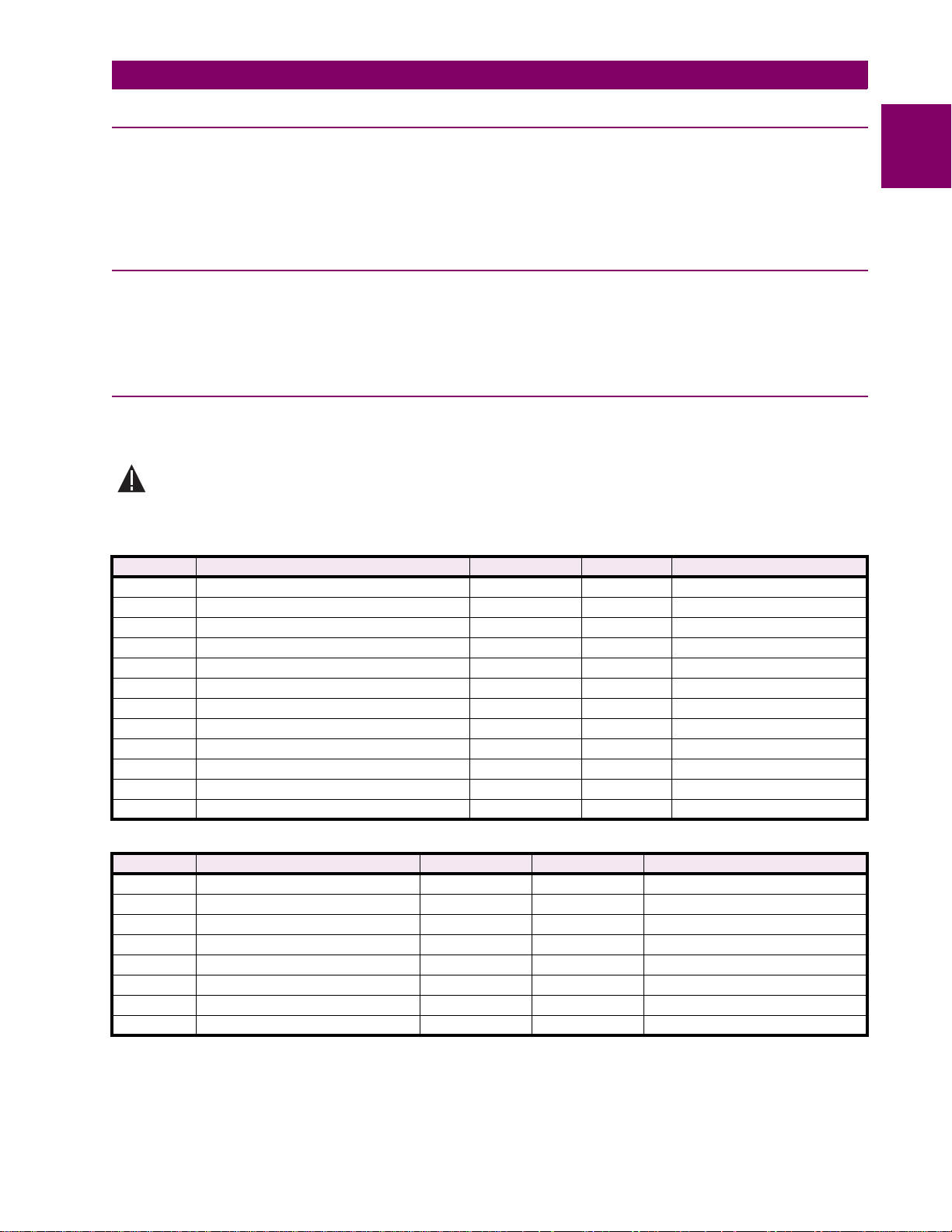
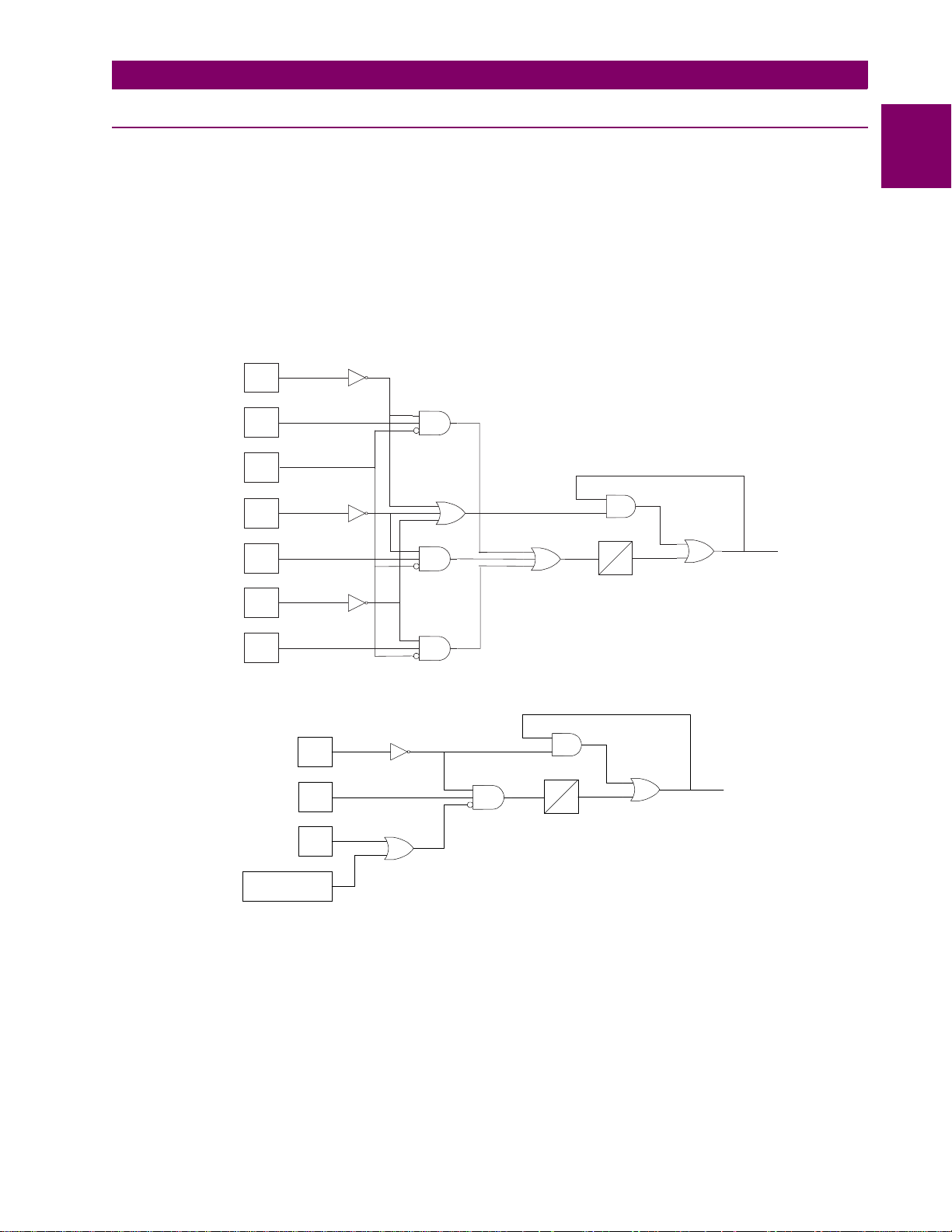
1.4 AUXILIARY PROTECTION FUNCTIONS 1.4.1 POTENTIAL TRANSFORMER FUSE FAILURE (PTFF)
Because a distance o r di rectio nal fun ction ma y o perate fo r a full or parti al los s of AC po tentia l caus ed by one or m ore blo wn
fuses, PTFF is provided to block distance and directional function tripping when a fuse failure is detected. If the backup
overcurrent functions 50, 50G, and 51G are not directionally controlled, they are allowed to trip during a potential fuse failure condition. If any of the backup, overcurrent functions, 50, 50G or 51G, is directionally supervised, then that function is
not allowed to trip. Rather, a second overcurrent function, 50_FF, 50G_FF, or 51G_FF is placed in service during the fuse
failure condition. The pickup level setting of these functions is independent from the normal pickup setting. The PTFF functional logic is shown below.
If AC potential is los t o n one or more phases, th e An y Phase Under Voltage signal pro duc es a lo gic 1 out put, and the upper
input is present at AND1. The phase undervoltage pickup setting is fixed at 75% of nominal and the pickup-to-dropout ratio
is virtually 100%. Th e lower in put to AND1 is d epende nt upon wheth er the fa ult dete ctor FD ha s opera ted or whethe r one or
more phases of the protected line are de-energized (open). When one or more phases of protected line are open, PTFF is
disabled.
PHASE
VOLTAGE
DETECTOR
CURRENT
DETECTOR
FAULT
DETECTOR
PHASE
VOLTAGE
DETECTOR
CURRENT
DETECTOR
PHASE
VOLTAGE
DETECTOR
VA
IB-A
FD
VB
IB-B
VC
1A
SINGLE PHASE TRIPPING MODELS:
1A
1B
1C
1B
2
2
3~
TL1
2
3
PTFF
0
1
CURRENT
DETECTOR
IB-C
1C
THREE PHASE TRIPPING MODELS:
3~
TL1
2
2
PTFF
0
PTFF3.VSD
VOLTAGE
DETECTOR
CURRENT
DETECTOR
FAULT
DETECTOR
ANY PHASE
OPEN
V1
IB
FD
1
1
1
Figure 1–3: POTENTIAL FUSE FAILURE LOGIC DIAGRAMS
If AC potential is lost for any reason, including a blown fuse or fuses, and there is no disturbance on the power system that
operates the fault detector, the AND1 output causes timer TL1 to time out and produce a PTFF output via OR2. The output
of OR2 is route d t o AND2 to seal-in the P TF F o utp ut, ba sed on the Any Phas e Unde r Voltage signal, s o that PTFF output is
maintained as long as th e pote ntial is below normal. Setti ng 714: FUSEFAIL determines whether PTFF operation blocks
distance/directiona l tr ipping (FUSEFAIL = YES) or merely is sues an eve nt (FUSEFAIL = NO). When t he pote ntial r eturns to
normal, the Any Phase Under Voltage signal resets to remove the seal-in, allowing the PTFF output to reset.
When a fault occurs, with an atte ndant d rop i n poten tial, th e Any Pha se Unde r Voltage signa l pick s up, but t he fa ult det ector
operates to prevent an output from AND1. PTFF does not operate on fault conditions.
GE Power Management
ALPS Advanced Line Protection System 1-11
Page 24

1.4 AUXILIARY PROTECTION FUNCTIONS 1 PRODUCT DESCRIPTION
1.4.2 LINE PICKUP
1
a) THREE PHASE TRIPPING
The Line Pickup (close-onto-fault) logic provides tripping in the event that the breaker is closed into a zero-voltage bolted
fault, such as occurs if the grounding chains were left on the line following maintenance. For this three phase zero voltage
fault, the Mho distance functions can not operate because they do not have a source of polarizing voltage. The logic is
shown below:
OVERREACHING PHASE OR
GROUND DISTANCE
I1 CURRENT
DETECTOR
ALL PHASES OPEN
ALL PHASE VOLTAGES
HIGH
MT
MTG
I1
TL402
40
401
45
5
TL401
150
90
0
FAST
RESET
402
TIMER
BYPASS
TL403
403
401
LINE PICKUP
TRIP
Figure 1–4: LINE PICKUP LOGIC DIAGRAM (THREE PHASE TRIPPING)
When the line is de-energized, the open breaker is detected by the All phases Open signal as shown in the above logic.
The resulting output causes timer TL401 to pickup 150 ms later. Consequently, when the line is energized and a fault current higher than the setting of I1 exists, current detector I1 picks up and AND402 produces an output. If the Timer Bypass
setting is set to YES, AND403 im medi ate ly prod uc es an o utp ut t o in itiate trip pin g of the bre ake r. If the Timer Bypass setting
is set to NO, then tripping occurs after the 45 ms pickup delay of timer TL403. Line Pickup is primarily intended to trip for
closing into zero-voltage bolted faults where the distance functions connected to line-side potential will not operate. However, regardless of the I1 pickup setting, it can also be used to trip on any type of permanent fault along the entire line
length that produces voltage at the relay location that is sufficient to operate a Zone 2 distance function, but not enough to
pickup the All Phase Voltages High s ignal . This i s acco mpli shed by routin g Zone 2 p hase-d istan ce or ground -distan ce function outputs to AND401. The step distance backup timers are bypassed by the Line Pickup logic.
If the line is energized and no fault exists, the all Phase Voltages High signal picks up and timer TL401 will begin timing; 40
ms later the output of TL402 resets timer TL401 via the fast reset input. AND401 and AND402 have their lower input
removed at that time to take the three phase Line Pickup out of service.
Timer TL403 is provided for those cases where simultaneous high-speed reclosing is employed at both ends of the line,
and where the I1 function must be set to pick up below the maximum load current that can occur at that time. TL403 then
allows time for the voltage to return to normal and take Line Pickup out of service before it can trip on load current. If simultaneous high-speed reclosing is not used, timer TL403 can be permanently bypassed.
b) SINGLE PHASE TRIPPING
Logic is included to provide high speed tripping when a single phase reclose onto a permanent fault occurs. When a phase
of the circuit breaker is open, the associated timer (TL404, TL405, and TL406) picks up to provide one input to an AND
gate (AND404, AND405, or AND406). This AND gate allows the associated Zone 2 ground distance function to trip without
time delay, and without receiving a permissive channel signal from the remote terminal. The single phase line pickup logic
will be blocked 90 ms after the breaker pole has been closed by the dropout of the timer.
1-12 ALPS Advanced Line Protection System
GE Power Management
Page 25
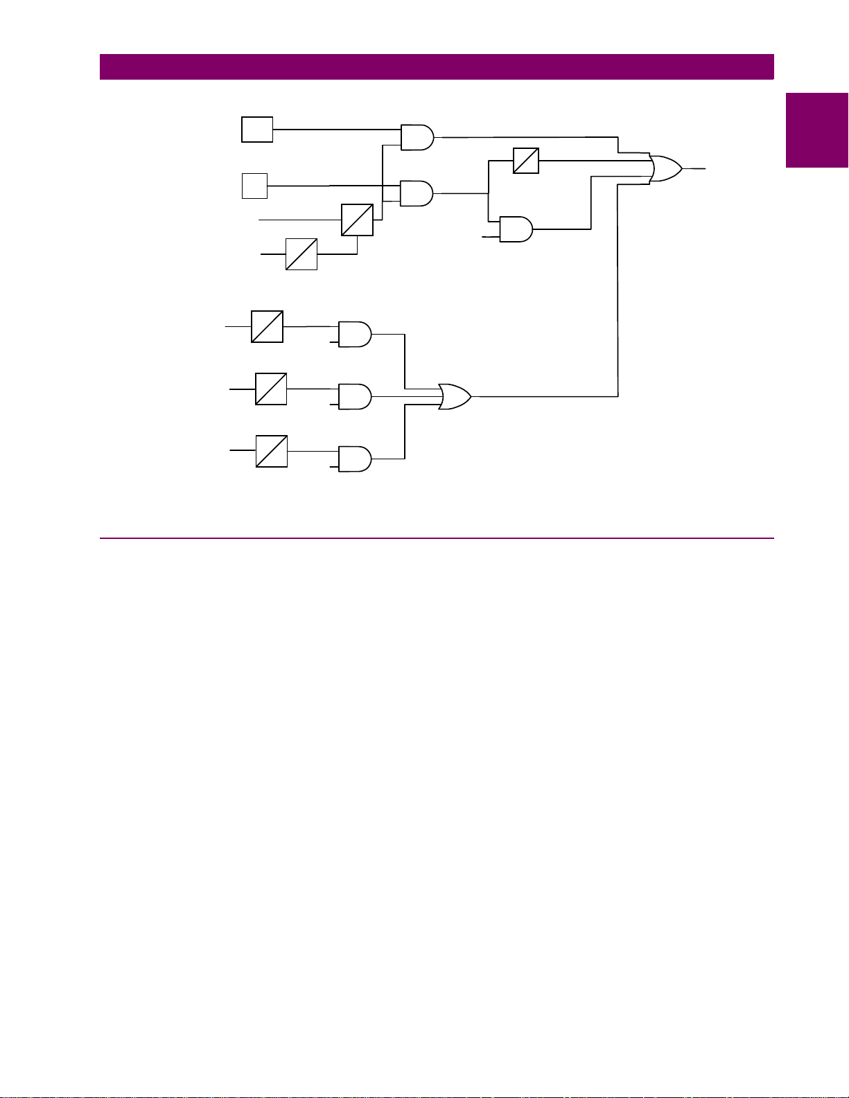
1 PRODUCT DESCRIPTION 1.4 AUXILIARY PROTECTION FUNCTIONS
OVERREACHING PHASE OR
GROUND DISTANCE
I1 CURRENT
DETECTOR
ALL PHASES OPEN
ALL PHASE VOLTAGES
HIGH
PHASE A
OPEN
PHASE B
OPEN
PHASE C
OPEN
Figure 1–5: LINE PICKUP LOGIC DIAGRAM (SINGLE PHASE TRIPPING)
MT
MTG
I1
TL404
150
TL405
150
150
90
90
TL406
90
TL402
40
MTG A
MTG B
MTG C
401
45
5
TL401
150
90
0
FAST
RESET
404
405
406
402
TIMER
BYPASS
402
TL403
403
401
LINE PICKUP
TRIP
1
1.4.3 REMOTE-OPEN DETECTOR
The Remote-Open Detector (ROD) function issues a trip signal when the remote breaker opens during an unbalanced
internal fault. This function detects that the remote breaker has opened by recognizing charging current on one or more
phases following opening of the remote breaker. As shown in the functional logic diagram of Figure 1–6: REMOTE-OPEN
DETECTOR LOGIC (ROD), the ROD output trips via OR2, AND1, OR2, AND2, OR3, and AND4. The Remote-Open Detector will not operate when a balanced three-phase fault is present.
ROD speeds up tri pp ing at the end of the line tha t o therwise would be th e s lo west to respond in a seq ue ntia l-tri pp ing c ond ition. In a Step Distance scheme, ROD tripping is beneficial for any unbalanced internal fault not detected by Zone 1. In a
Blocking scheme, ROD tripping is beneficial where system conditions are such that the fault current redistribution following
breaker opening at one end is normally required before the other end(s) operates. The ROD function should not be considered as a replacement or substitute for pilot schemes.
Figure 1–6: REMOTE-OPEN DETECTOR LOGIC (ROD) is a functional logic diagram of the ROD function. The sequence
of events that results in an ROD output is as follows:
1. No charging current is detected prior to the fault – logic 0 output from AND2.
2. A fault is detected – logic 1 output from OR3.
3. The remote breaker opens – logic 1 output from AND3.
4. The fault is still present, so the two inputs to AND4 persist for the time-delay setting of timer TL20.
If charging current is initially detected but the fault detector (FD) is not picked up, indicating no fault on the power system,
then OR1 and AND1 produce outputs. AND2 produces an output and seals-in on the output of OR1 via OR2. AND3 is now
blocked from pro duc in g a n outp ut as lo ng as charging current is dete cte d, regardless of whethe r FD is picked up or not. If a
subsequent fault occurs and the remote breaker opens, ROD is prevented from producing an output.
GE Power Management
ALPS Advanced Line Protection System 1-13
Page 26
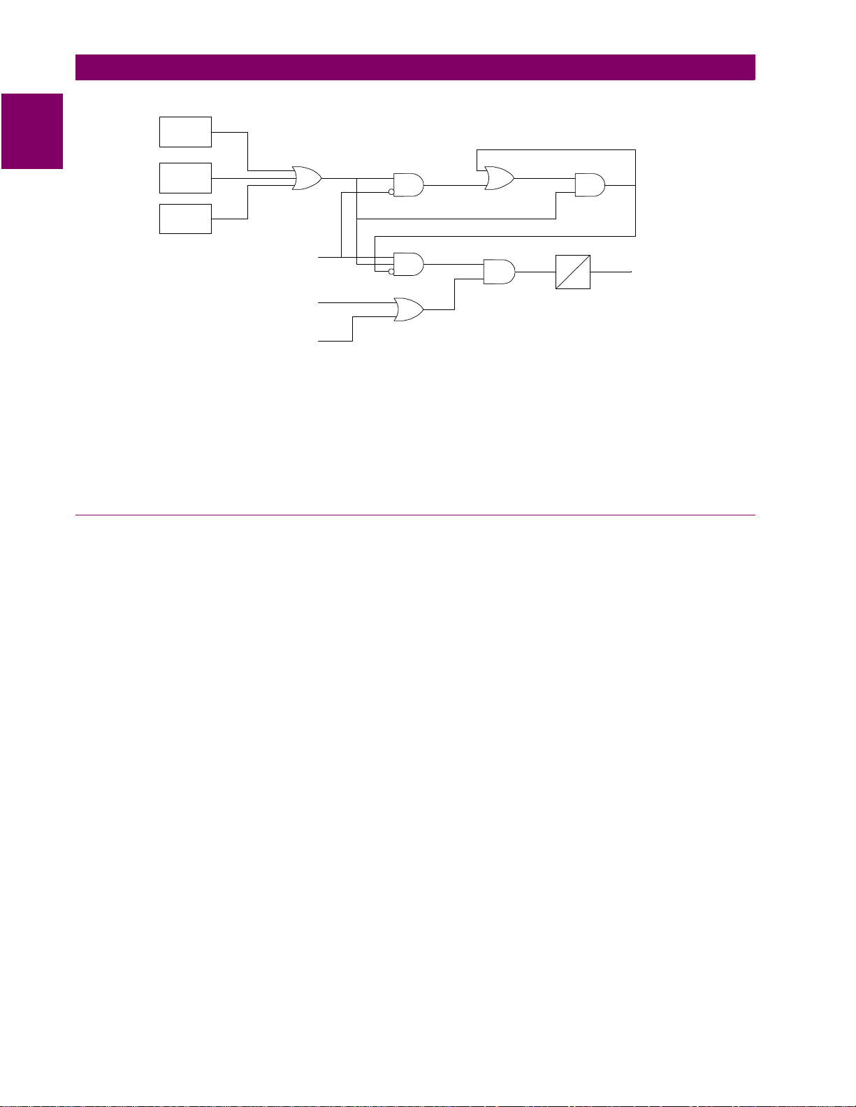
1.4 AUXILIARY PROTECTION FUNCTIONS 1 PRODUCT DESCRIPTION
1
IA LEADS
VA BY 90°
IB LEADS
VB BY 90°
IC LEADS
VC BY 90°
1
FAULT
DETECTOR
ANY ZONE2
PHASE-DISTANCE
FUNCTION
ANY ZONE2
GROUND-DISTANCE
FUNCTION
1
3
2
4
2
TL20
A
0
A = 10 - 100
TRIP
3
RemoteOpen.vsd
Figure 1–6: REMOTE-OPEN DETECTOR LOGIC (ROD)
If sufficient load current is flowing prior to the fault there is no output from OR1, indicating that no charging current is
detected, and AND3 is not blocked, since there is no output from AND2. If an unbalanced fault subsequently occurs, FD
blocks AND1 to prevent an AND2 output. AND3 is allowed to produce an output when the remote breaker opens, provided
there is sufficient charging current to operate one or more of the three charging-current-detectors that are the inputs to
OR1. The capacitive cha rging cu rrent must be 60 mA or mo re (se condary ph ase cur rent) to assure operatio n of ROD. If the
fault is still present as indicated by an output from OR3, an ROD trip follows the expiration of the TL20 security time delay.
1.4.4 OUT-OF-STEP BLOCKING
Figures 1–7: OSB R-X DIAGRAM and 1–8: OSB LO GIC D IAGRAMS rep resent the funct ional l ogic di agrams for out-of -step
blocking and an R-X diagram depicting an assumed swing-impedance locus superimposed on the associated distance
relay characteristics. For an out-of-step condition, the impedance locus will first enter the MOB characteristic, then later
enter the MT (phase-distance trip function) characteristic.
When MOB (A-B) picks up durin g the power s wing , it applies the middle input to AND 20 1. The top i npu t is p res ent fro m th e
NOT via OR202, since MT (A-B) has not operated yet. The bottom NOT input of AND202 is satisfied, since it is assumed
that no phase is open, and the AND202 output energizes timer TL1.
If the impedance stays between the MOB and MT characteristics for the pickup time of TL1, an OSB output results. The
OSB output is routed back to the top input of AND202 via OR202 to seal-in the OSB output for as long as MOB is picked
up. The OSB output resets 50 ms after the swing-impedance locus leaves the MOB characteristic. The same logic is
repeated for the distance functions associated with phase pairs B-C and C-A. OSB can be selected to block tripping of:
1. All functions (Protection Setting 1603: BLOCKWHAT = BLKALL)
2. All distance functions (Protection Setting 1603: BLOCKWHAT = BLKDIST)
3. Only the phase distance functions (Protection Setting 1603: BLOCKWHAT = BLKPHAS)
4. No functions (Protection Setting 1603: BLOCKWHAT = BLKNONE)
For selections 2 an d 3, each of the fou r distan ce zones (Zone 1, 2 , 3, or 4) ma y be ind ividu ally s elect ed to be bl ocke d or not
via Protection Settings 1604 through 1607 (BLOCKZ1, BLOCKZ2, BLOCKZ3, and BLOCKZ4).
Timer TL1 has an adaptive pickup feature with an initial pickup setting of 30 ms for the first slip cycle; the pickup delay
becomes progressively lower during successive slip cycles. This improves the capability to maintain the out-of-step output
during the increasing slip frequencies typically encountered after the first slip cycle.
1-14 ALPS Advanced Line Protection System
GE Power Management
Page 27
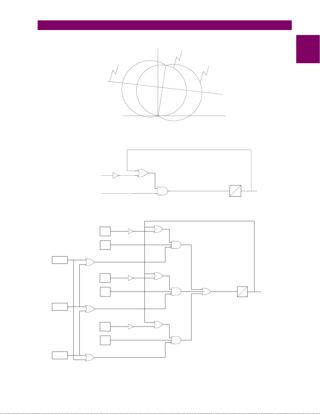
1 PRODUCT DESCRIPTION 1.4 AUXILIARY PROTECTION FUNCTIONS
SWING IMPEDANCE
LOCUS
ALPS WITH THREE-PHASE TRIPPING:
OSB3P.VSD
ANY COORDINATING ZONE
(PHASE OR GROUND)
ANY MOB
ALPS WITH SINGLE-PHASE TRIPPING:
X
MT (ZONE 2 / 3 / 4)
Figure 1–7: OSB R-X DIAGRAM
202
202
MOB
R
OSBRXDiag.CDR
TL1
*
50
30 ms. INITIAL PICKUP TIME
*
ADAPTIVE AFTER FIRST SLIP CYCLE
OSB
1
PHASE A
OPEN
PHASE B
OPEN
PHASE C
OPEN
204
205
206
MT
A - B
MOB
A - B
MT
B - C
MOB
B - C
MT
C - A
MOB
C - A
201
201
202
202
203
203
Figure 1–8: OSB LOGIC DIAGRAMS
TL1
207
* 30 ms. INITIAL PICKUP TIME
ADAPTIVE AFTER FIRST SLIP CYCLE
*
50
OSB1P.VSD
OSB
GE Power Management
ALPS Advanced Line Protection System 1-15
Page 28

1.5 OTHER FEATURES 1 PRODUCT DESCRIPTION
1.5 OTHER FEATURES 1.5.1 FLASH MEMORY
1
The program code resides in Flash memory rather than EPROM. This new technology provides the same functionality during normal operations of the relay. The advantage to the Flash Memory is it can be changed for software upgrades without
opening the relay. The contents can be overwritten through the communications ports already provided in the relay. The
ability to change the cont ents requires special sof tw are an d do es no t come with any of the standa rd co mm uni ca tio ns pack ages available for the ALPS.
1.5.2 LINE OVERLOAD
The Line Overloa d fu nct ion pro vid es an event and a programmabl e s ig nal . Thi s signal can be used to p rov ide al arm ind ic ation (contact closure) that the load current on the protected line has exceeded a set level for a set time interval. Two alarm
levels are included. Level 1 is generally set with a lower pickup setting and a longer time delay than level 2.
1.5.3 CURRENT UNBALANCE DETECTION
If the Fault Detector remains picked up for 60 seconds, a non-critical alarm is issued and an event message generated.
This function indicates sustained unbalanced current conditions such as a shorted or open current transformer.
1.5.4 FAULT LOCATION
A separate algorithm provides fault-loca tio n in form ati on , whi ch is pres en ted as mi les, kilometers, or perce nt of l ine from th e
relay location to the faul t. Th e d is tanc e t o th e fault is based on a li ne l eng th p rov ide d by the user as a setting. Fault location
output is displayed on the front panel liquid crystal display as part of the target information following a relay trip, and it is
also contained in the Fault Report described below.
1.5.5 FAULT REPORT
When a fault or oscillography trigger occurs, pertinent information, consisting of unit ID, date and time, operating time, prefault currents, fault currents and voltages, fault type, trip type, distance to fault, and selected events, is stored in memory.
The number of fault ev ents that are stored is selectable by the user. A relay with sta nda rd m em ory op tio n m ay be s et for: 2,
4, 8, or 12 fault reports. A relay with extended memory option may be set for 6, 12, 24, or 36 fault reports. Each fault report
is associated with an oscillography data file. See Section 8.2.3: REQUEST FAULT INFORMATION on page 8–17 for
obtaining a fault report through the local user interface and Section 11.6: INFORMATION on page 11–14 for fault reports
using ALPS-Link.
1.5.6 OSCILLOGRAPHY
Oscillography data are stored in memory each time the ALPS issues a trip and, optionally when an internal oscillography
trigger flag is set or an external contact is closed. Protection Setting 2026: CONFOSC, allows a configurable oscillography
trigger to be assigned by Xpression Builder. Note that OSC Trigger stores oscillography data, but does not necessarily set
t = 0, the time sample that delineates between prefault and postfault oscillography cycles. The term
defined as the numbe r of cy cl es of o sc il log raph y d ata (prefault plus postfault) as de term in ed by General Setting 301: NUM-
FAULTS. If the internal Fault Detector, FD, comes up initially and OSC Trigger follows within the disturbance period, oscillography data are stored whether or not the ALPS issues a trip.
If the ALPS issues a trip, then a normal fault report is stored as part of the oscillography data. If the ALPS does not issue a
trip, a pseudofault report is created. The trip type is listed as OSC, the trip time is set to when the OSC Trigger occurred,
the operating time is set to zero, and the fault type and location are computed, based on post-OSC Trigger data. The local
LCD display does not show target information, but an event message and fault report are stored in memory. In either case
above, t = 0 is determined by the internal Fault Detector (FD).
If OSC Trigger comes up initially and FD follows within the disturbance period, the same actions occur and FD determines
t = 0. If only OSC Trigger occurs, then a pseudofault report is created and OSC Trigger determines t = 0. This arrangement
assures that the oscillography function always captures an ALPS trip, with FD determining t = 0, regardless of whether an
optional internal or external trigger is used.
disturbance period
is
1-16 ALPS Advanced Line Protection System
GE Power Management
Page 29

1 PRODUCT DESCRIPTION 1.5 OTHER FEATURES
Oscillography data include station and line identification, a complete list of the active relay settings, the fault report, internal
flags, and a selectable number of prefault and postfault data samples. Further information on reading oscillography with
ALPS-Link is found in Section 11.6.5: OSCILLOGRAPHY REPORT on page 11–15. The ALPS does not store flags for
functions that are disabled. For example, if Protection Setting 104: Z1GROUND = NO and a Z1 ground fault is applied, the
Zone 1 ground flag will not operate or be stored.
1.5.7 PLAYBACK
The ALPS has the ability to replay stored digital current and voltage signals from oscillography files through the protection
algorithms. The currents and voltages may be obtained from a factory stored file, from any oscillography file currently
stored in the relay, or from an oscillography file stored on a PC. See Section 8.1.20: PLAYBACK on page 8–13 for a complete description of the Playback feature.
1.5.8 SEQUENCE OF EVENTS
This function time tags and stores the last 150 events in memory. The resolution of the time-tagging is 1 millisecond. The
event list contains power system events, operator actions, and self-test alarms. The sequence of events can be accessed
remotely via the front panel port, PL-1 or PL-2, and a PC. A full event list contained in Section 8.2.7: EVENT INFORMATION on page 8–19.
1.5.9 EQUIPMENT DUTY
When the ALPS is applied with a single breaker, it incorporates the ability to monitor the number of breaker operations and
the breaker duty. Alarm levels can be set for both the total number of breaker operations and the total equipment duty. See
Section 2.2.4: EQUIPMENT DUTY on page 2–6 for a complete description of the Equipment Duty feature.
1
1.5.10 SELECTABLE GROUPS OF SETTINGS
Four separate groups of protection settings may be stored in nonvolatile memory. Only one group can be active at a given
time, but the active group may be selected by external contacts, by a command issued from the local keypad, or remote
communication software. If the selection is to be made by an external switch, then two of the digital inputs (contact converters) are used for this purpose. A four position SB1 or SBM switch with two stages (two effective contacts) could be used to
select the active group of settings, as shown Figure 1–9: SWITCH SELECTION OF ACTIVE SETTING GROUP below.
For this example, CC5 has been assigned to “CGST2” (Change Setting Group Input, Bit 1) and CC6 has
been assigned to “CGST1” (Change Setting Group Input, Bit 0). Other contact converters may be assigned
NOTE
to these functions.
GE Power Management
ALPS Advanced Line Protection System 1-17
Page 30
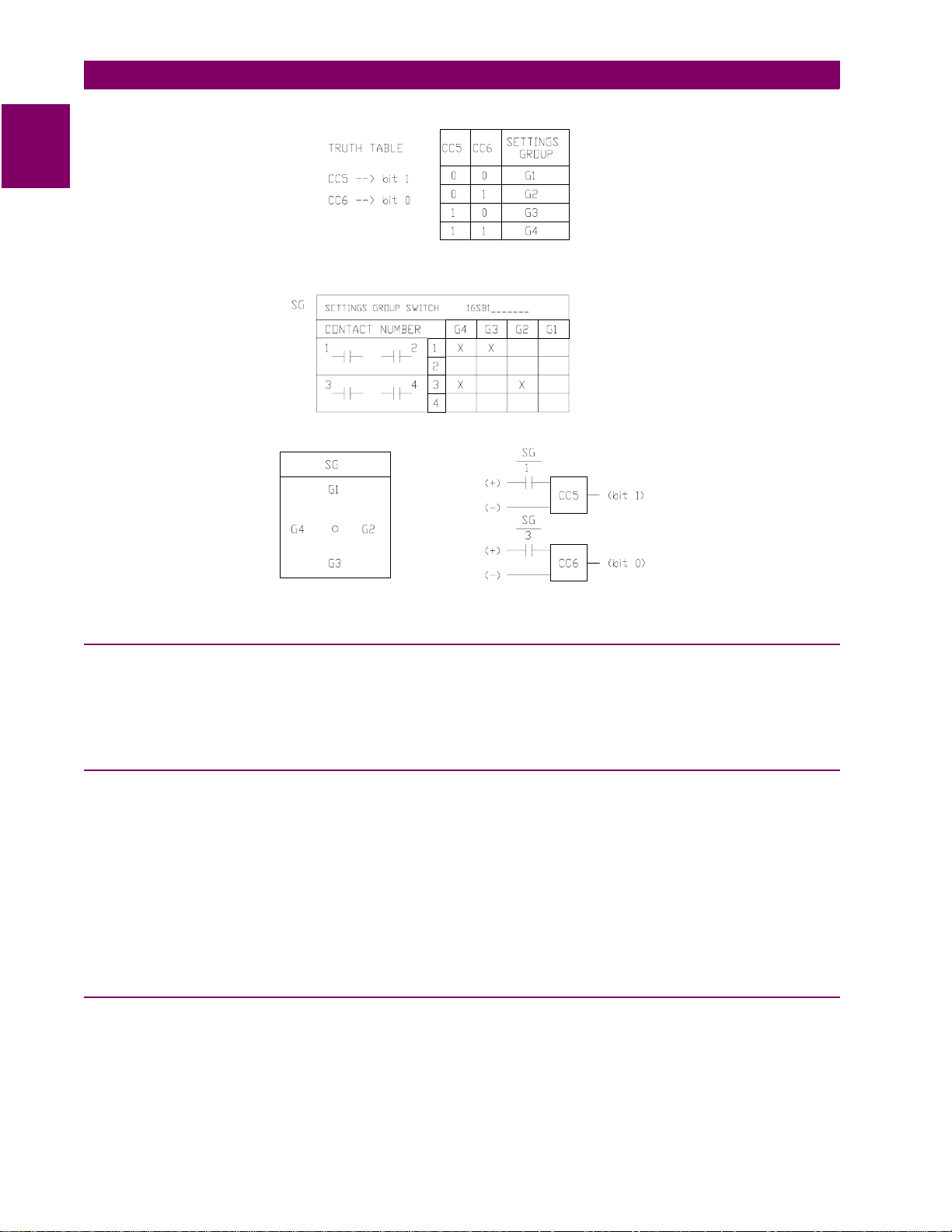
1
1.5 OTHER FEATURES 1 PRODUCT DESCRIPTION
Figure 1–9: SWITCH SELECTION OF ACTIVE SETTING GROUP
1.5.11 TIME SYNCHRONIZATION
The ALPS includes a clock that can run freely from the internal oscillator or be synchronized from an external signal. An
unmodulated IRIG-B signal connected to the IRIG-B terminals, located on terminal block “D” on the rear panel, may be
used to synchronize the clock. The clock in a given ALPS is synchronized to within ±1 ms of any other ALPS clock, if the
two relays are wired to the same synchronizing signal.
1.5.12 TRIP BUS CHECK
After a settings change is made in the active settings group, the ALPS automatically returns to its normal protection-on
mode following storage of the new setting values in nonvolatile memory.
A Trip Bus Check to determine that the changed settings have not caused any of the trip functions to operate for system
conditions (that is, current and voltage at the relay) at that instant. A Trip Bus Check also occurs before a newly selected
settings group is allowe d to become the active settings group. If Trip Bus Check finds a pi cked-up trip function , protect ion is
turned off and a critical alarm is issued.
This check provides a degree of confidence in the new settings, but it does not guarantee that one or more trip functions
might not operate as system co nd itio ns chan ge. For example, a subsequent increase in load current might cause the Zone
3 phase-distance function to operate, even though it did not operate at the instant the Trip Bus Check was made.
1.5.13 TRIP CIRCUIT MONITOR
Within the ALPS relay system the DC battery voltage across each of the open trip contacts (or SCRs) may be continuously
monitored to determine if the associated trip circuit is intact. If the monitored DC voltage drops to zero, then the trip circuit
has failed to op en, or the bre ak er 5 2/a contact, which is no rma ll y wi red in series with the trip c oil , h as op ene d. This function
is intended to replace the red light indicator typically used for trip-circuit monitoring, and it can be selectively disabled for
each breaker.
1-18 ALPS Advanced Line Protection System
GE Power Management
Page 31

1 PRODUCT DESCRIPTION 1.5 OTHER FEATURES
There are four trip contact s (or SCRs ) in the ALPS. Th e volta ge a cro ss ea ch c on tac t (or SCR) i s moni tore d s epa rate ly. Any
combination of trip circuits may be monitored by General Setting 107: NUM_MON.
Operation of the Trip Circuit Monitor causes a noncritical alarm event. If one or more breaker poles are opened in some
manner other than by a trip issued by the ALPS, then the 52/a contact normally wired in series with the trip coil opens and
drops the voltage across the open contact to zero. To avoid a non-critical alarm for this condition, closure of the associated
52/b contact disables the Trip Circuit Monitor function for the involved pole.
1.5.14 ALARMS
Two separate alarms are provided. The output relays associated with these alarms are not user programmable. Both of
these alarms have form C contacts and are energized under normal conditions.
• The critical alarm de-energizes when the relay self-test logic detects a problem that warrants taking the relay system
out of service.
• The power supply alar m de-energiz es when the po wer supply fails or is turned off.
A user programmable non-critical alarm is also provided. Operation of the non-critical alarm will cause an event to be
logged, and may be programmed to a user-assigned output contact. The non-critical alarm is de-energized in normal conditions. The default inputs to the non-critical alarm include the following conditions:
1. Trip Circuit Alarm
2. Zone Flags On Alarm
3. Overcurrent Alarm
4. Unbalance Current Alarm Detector
Additional inputs, such as line overload alarm, may be added by the user via Xpression Builder.
1
1.5.15 METERING
Metering values may be obtained by using the keypad or through remote communications. The following quantities are
available: RMS voltage an d current , phasor voltage and curren t, W att s, Vars, Power Factor, system frequenc y, and Breaker
health. The voltage and c urre nt va lu es a re ac cu rate to 1% of rea din g. Refe r to C ha pte r 8: LOC AL USER INTER FACE for a
description on how to use the metering function.
1.5.16 BREAKER CONTROL
Two different breakers may be selectively tripped or closed via the local keypad or a remote PC connected to the RS232
port. The commands are as follows :
• Trip Breaker 1 and Trip Breaker 2 use the same output contacts or SCRs as a fault trip command.
• Close Breaker 1 and Close Breaker 2 use separate auxiliary relays. The contact of each auxiliary relay must be wired
to the appropriate breaker’s close circuit.
Remote breaker tripping and closing are enabled or disabled with a jumper on the as shown in Figure 3–5: INPUT BOARD
DIAGRAM on page 3–7. The ALPS is shipped from the factory with this jumper and Breaker Control enabled. Install the
jumper to disable Remote Breaker Control.
GE Power Management
ALPS Advanced Line Protection System 1-19
Page 32

1.6 COMMUNICATIONS 1 PRODUCT DESCRIPTION
1.6 COMMUNICATIONS 1.6.1 KEYPAD AND DISPLAY
1
A local user interface, incorporating a keypad and display, is provided to enter settings, display present values, view fault
target information, and access stored data (see Chapter 8 for details). Passwords provide security for keypad access.
Three separate passwords provide local keypad security against inadvertent breaker operations and settings changes. No
password is required to view data stored in the relay. The three levels of password protection are:
CONTROL: Allows control operations (trip and close the breakers).
SETTINGS: Allows settings changes.
MASTER: Allows both control ope rations and settings changes.
Refer to Section 8.1.21: CHANGE PASSWORD on page 8–14 for a description of the keypad password usage.
1.6.2 SERIAL COMMUNICATIONS
A DB-9 plug RS232 port (Port 1) on the front panel provides local serial communication via an IBM PC-compatible computer. One or two rear p orts (RS2 32 or RS4 85) are pr ovided f or serial communi cations . Port 2 i s standar d on all mode ls.
When Port 2 is c onf igu r ed as RS 23 2, co nne cti on is made using a D B2 5 p lug; when Port 2 is co nfi gured as RS485, connec tion is made using a 4-pin Phoenix plug. Port 3 is optional (depending on the model) and uses a DB25 plug for either
RS232 or RS485. The communications protocol for each port may be selected independently as either GE-Modem, ASCII,
or DNP 3.0. Each por t ma y b e se t in dep endently for data communi cat ion s fro m 3 00 t o 96 00 bps. In addition, Port 2 ha s th e
ability to accept a plug in communication module that can support the Modbus RTU communications protocols.
Four different pas swo rds provide remo te seria l commun icati ons se cur ity. The level s of pas sword prot ection for comm unic ations are:
VIEW: Allows remote access to the ALPS to view and retrieve stored data.
CONTROL: Allows control operations (trip and close the breakers).
SETTINGS: Allows settings changes.
MASTER: Allows both control ope rations and settings changes.
Refer to Chapter 11: ALPS-LINK USER GUIDE for a description of AL PS-Li nk and Chap ter 1 2: ASCII COM MUNICATIONS
for ASCII port password usage. The Modbus memory map and DNP 3.0 protocol information are contained in Appendices
B and C, respectively.
1.6.3 SCADA DIGITAL TO ANALOG (DTA) INTERFACE
An internal DTA function, standard on the ALPS, provides the following:
• An analog output proportional to the distance from the relay to the fault as calculated by the fault-location algorithm.
• Four contact outputs that provide fault-type information.
The analog output is intended to be wired into an analog port of a SCADA RTU to provide remote indication of distance to
the fault. The four c ontact output s ar e desi gnated phase A, phas e B, pha se C , and ne utral a nd are i ntende d to be wired into
four separate RTU digital ports. A particular contact closes when its phase (or neutral) is involved in the fault. For a phase
B-to-C-to-ground fault, the phase B, phase C, and neutral contacts close.
The DTA provides either a nominal 0 to 1 mA DC output or a nominal 0 to 5 V DC output. The choice of output ranges is
made by a switch located on the Processor Board. The Processor Board must be removed from the ALPS chassis to
access this switch. For the proper sequence, see Chapter 9: SERVICING.
When the fault location is calculated to be 100% of the line length, the DTA output is either 0.8 mA DC or 4.0 V DC. The
DTA output goes to full scale (either 1 mA DC or 5 V DC) when the fault location is calculated to be greater than 110% of
the line length. Consequently, the usable output ranges are 0 to 0.88 mA DC or 0 to 4.4 V DC, which covers the 0 to 110%
fault-location range. The SCADA system should be programmed to recognize a full-scale output as an indication of an
invalid output, resulting from either an out-of-limit fault-location calculation or a DTA reset.
Two s etti ngs ar e as s oci ate d wi th th e SC ADA D TA Interface. FLTLOCK specifies a time after a f aul t du rin g whi ch fau lt-l oc ation calculations resulting from subsequent faults are prevented from updating the fault-location information stored in the
DTA logic. FLTRESET specifies the time after a fault at which the fault-location information stored in the DTA logic is reset
(output forced to full-scale value) and those fault-type contacts that have closed will open. When either the ALPS date or
time is changed the timers associated with FLTLOCK and FLTRESET are reset and the DTA logic is reset. Fault phase
identification dry contacts for A, B, C, and N phases must be programmed by the user. Refer to Chapter 3 for details.
1-20 ALPS Advanced Line Protection System
GE Power Management
Page 33

1 PRODUCT DESCRIPTION 1.7 SELF-TEST FEATURES
1.7 SELF-TEST FEA T URES 1.7.1 START-UP SELF-TESTS
The most comprehensive testing of the ALPS is performed during a power-up. Since the ALPS is not performing any protection activities at that time, tests (such as RAM tests) that would be disruptive to run-time processing are performed.
Both processors participate in the start-up self-testing. The processors communicate their results to each other so that any
failures can be reported and so that each processor successfully completes its assigned self-tests before the ALPS begins
protection activity.
During power-up, both microprocessors perform start-up self-tests on its associated hardware (including Flash Memory,
EPROM, local RAM, shared RAM, interrupt controller, timer chip, serial I/O ports, nonvolatile memory, analog and digital I/
O circuitry, and Keypad/ LCD D isplay hard ware). In additi on, the ALPS veri fies t hat the PROM v ersio n numb ers on both p rocessor boards are compatible, and that the Model Number stored in nonvolatile memory agrees with the unit’s configuration. The components tested at start-up are listed in Table 9–1: COMPONENTS TESTED DURING START-UP TESTS on
page 9–2.
In most cases, if any critical self-test failure is detected, the ALPS discontinues start-up and does not reset. It attempts to
store the ALPS status to initialize the KEYPAD/LCD DISPLAY and remote communications hardware/software for communicating the status. The critical alarm output is energized.
If no failures are detected, the ALPS completes initialization of its hardware and software; this includes reading information
from the serial Nonvolatile RAM (NVRAM) in the magnetic module, stored during the manufacturing process, to determine
the current rating of the m agn eti c in the un it (1 A or 5 A). Next, the 960 p rocessor enables the ou tpu ts. As the final step, th e
ALPS checks the results of all the tests to determine whether to turn on the green status LED on the front panel.
The start-up procedure takes approximately one minute. As soon as the 960 CPU successfully completes its PROM test
and initializes the display hardware, the message "INITIALIZING" appears on the display. When all ALPS initialization is
completed satisfactorily, the ALPS message is displayed and the ALPS begins acquiring and processing data.
1.7.2 RUN-TIME SELF-TESTS
1
Both of the processors have idle time when the ALPS is not performing fault or post-fault processing. During this idle time,
each processor performs background self-tests that do not interfere with the foreground tasks’ use of serial and parallel
ports and that do not inhibit interrupts to any processor. If any background self-test fails, the test is repeated. For a component to be declared as fai led, the test m ust fail three co nsec utive t imes. In the case of most critic al failu res, the ALPS forc es
a reset to attempt to get the failed component working again.
The ALPS is able to distinguish between a start-up (power-up) and a reset caused automatically by a ALPS malfunction.
The reset is a fault-tolerant feature of the ALPS; it is performed as an attempt to resume operation after an intermittent failure. The reset activities are identic al to the s tart-up ac tivities excep t that not all start-up s elf-tests are performe d. If the r eset
was caused by failure of a specific background self-test, then only the start-up self-tests associated with that same hardware are performed.
A reset is not reported b y the AL PS. If the re set is succ essf ul no fa ilure s tatus is record ed and t he cr itic al alar m outp ut is not
energized; however, during the reset procedure, the red LED on the front panel is lit and a failure code may appear on the
display. Therefore, if the reset is not successful, the processor board is shut down, leaving the Keypad/LCD Display displaying the error information. Refer to Chapter 9.2.7: SERVICE SYSTEM STATUS FAILURES on page 9–5. To prevent
continual resets in the case of a solid failure, both hardware and software permit only four resets in a one-hour period. On
the fifth reset, the ALPS does not initialize, but attempts to initialize the display, communications, and the critical-alarm output, as in the case of a start-up with a critical self-test failure. The reset procedure takes approximately one second,
depending upon which start-up self-tests are to be run.
The components tested in the background are listed in Table 9–2: RUN-TIME BACKGROUND SELF-TESTS on page 9–2.
Testing of I/O hardware is done in the foreground, so that the processors know when a given component or port is in use
and not available for testing. The components tested in the foreground are listed in Table 9–3: RUN-TIME FOREGROUND
SELF-TESTS. Some foreground tests are performed every sample period, while others are performed less frequently.
As with background se lf-test s, any fa iled fo reground test is repe ated and must fail th ree consec utive times to be con sidered
a failure. Although no t spec ifically a self- test, the trip ci rcuit c ontinu ity mo nitorin g is pe rformed as a fore ground t est. R efer to
Section 1.5.13: TRIP CIRCUIT MONITOR on page 1–18 of this chapter.
The operator may initiate a visual-response test of the KEYPAD/LCD DISPLAY components. Refer to Chapter 4: ACCEPTANCE/PERIODIC TESTS for details.
GE Power Management
ALPS Advanced Line Protection System 1-21
Page 34

1.7 SELF-TEST FEATURES 1 PRODUCT DESCRIPTION
1.7.3 CONTINUOUS MONITOR
1
The ALPS relay includes a Continuous Monitor feature in addition to its self test features. The Continuous Monitor is
intended to detect any ALPS tripping units (Zone 2 or Zone 3 distance functions, 50G or 50 overcurrent functions) that are
in the picked up condition without a corresponding operation of the Fault Detector. If such a condition occurs and persists
for 1 second, the ALPS relay will issue a Non-Critical Alarm and log a Continuous Monitor event.
These Continuous Monitor Alarm points are found in Table 2–10: INDEX NUMBERS – SCHEME, RECLOSER, & PROGRAMMABLE LOGIC on page 2–52. The Index numbers used for the Continuous Monitor are as follows:
• 48: Trip Circuit alarm
• 49: ZONE flags on alarm
• 50: Overcurrent Alarm
• 51: Unbalanced Current Detector alarm.
They are assigned in the default settings as inputs to the non-critical alarm. These flags may also be used in configurable
logic, or assigned to other alarm contacts if required.
1-22 ALPS Advanced Line Protection System
GE Power Management
Page 35

1 PRODUCT DESCRIPTION 1.8 PROTECTION SCHEMES
1.8 PROTECTION SCHEMES 1.8.1 INTRODUCTION
The six standard protection schemes are described in this section. Functional logic diagrams Figure 1–10: STEP DISTANCE LOGIC DIAGRAM through Figure 1–18: HYBRID LOGIC DIAGRAM show the scheme logic for the protection
schemes using conventional AND/OR combinational logic. The elementary diagrams on pages 1–49 to 1–52 show the
external connections to the ALPS relay system. Note that all of the output relays and input contact converters included in
the ALPS are fully programmable by the user. However, for ease of application, the ALPS relay is shipped with the inputs
and outputs assigned as shown in Figure 1–27: ELEMENTARY DIAGRAM WITH DEFAULT I/O (SINGLE PHASE TRIPPING) on page 1–49 and Figure 1–28: ELEMENTARY DIAGRAM WITH DEFAULT I/O (THREE PHASE TRIPPING) on
page 1–50. The programmability of the ALPS is discussed in Chapter 13: XPRESSION BUILDER. Figures 1– 11: INTERCONNECTION DIAGRAM FOR PUTT/POTT WITH NS40A through 1–17: INTERCONNECTION DIAGRAM FOR BLOCKING SCHEME WITH CS61C on pages 1–25 to 1–32 show typical interconnections between the ALPS and an appropriate
carrier/tone equipment for three pilot schemes:
• BLOCKING with NS40A
• POTT with CS28A
• HYBRID with Unblocking CS61C
1.8.2 STEP DISTANCE
Figure 1–10: STEP DISTANCE LOGIC DIAGRAM on page 1–27 is the logic diagram for the Step Distance scheme for the
ALPS single phase and three phase models, respectively. Since this non-pilot scheme overlays the other protection
schemes in the ALPS, it is in essence a part of all of them. The Zone 1 distance functions are set to reach no greater than
90% of the positive-sequence impedance of the protected line. All of the ground-distance functions are provided with selfcompensation so that they see only the positive-sequence impedance to a ground fault when the compensation setting is
properly selected to reflect the difference between the zero-sequence and positive-sequence impedance of the line. This
setting is explained in Chapter 2: CALCULATION OF SETTINGS.
There can be as many as three time-delayed zones. At a minimum, Zone 2 should be selected to provide protection for the
last 10% of the protected line not covered by Zone 1. If the application permits, a forward-looking third zone can be used to
provide backup protection for adjacent line sections out of the remote bus. If a reverse-looking zone is desired, the Zone 4
functions can be rev ersed. For som e appl icatio ns it may be des irabl e to im plement b oth a for ward-l ookin g Zone 3 and a f orward-looking Zone 4.
The phase-distance functions can be placed in or out of service by specifying a separate setting for each protection zone.
The same is true for the ground -distanc e functi ons. Zon e 2, Zone 3, and Zone 4 each have two ind epend entl y set zone tim ers. One timer is associated with the phase functions, the other with the ground functions.
1
GE Power Management
ALPS Advanced Line Protection System 1-23
Page 36

1
1.8 PROTECTION SCHEMES 1 PRODUCT DESCRIPTION
PHASE
DISTANCE
ZONE 1
GROUND
DISTANCE
PHASE
DISTANCE
GROUND
ZONE 2
DISTANCE
OVERREACHING ZONE /
REMOTE
OPEN
PHASE
DISTANCE
GROUND
ZONE 3
DISTANCE
PHASE
DISTANCE
GROUND
ZONE 4
DISTANCE
REVERSIBLE
PHASE
BACKUP
GROUND
BACKUP
50P
50G
51G
TL3P
C
TL3G
TL4P
TL4G
0
C
D
D
1
B = 0.2 to 3.0 sec.
TL2P
B
TL2G
B
0
C = 0.4 to 6 sec.
11
0
12
28
(ZONE 4)
0
0
D = 0.4 to 6 sec.
OSB
0
(ZONE 3)
11
OSB
11
OSB
4
(ZONE 2)
8
OSB
10
OSBALL
FFB
Setting 714
13
(CNFTRP)
CONFIGURABLE
TRIP BUS
(TRIP)
7
7
44
TRIP
BUS
13
LINE PICKUP
FAULT
DETECTOR
OVER-
CURRENT
SUPERVISION
OUT OF STEP
BLOCKING
LOGIC
IT
IB
SUPERVISE
ZONE 4
OSB
Settings 1601 to 1607
Figure 1–10: STEP DISTANCE LOGIC DIAGRAM
9
9
BLOCK
RECLOSING
Settings 801-810
6
8
(RI)
RECLOSE INITIATE
(CANCL)
RECLOSE CANCEL
STP_DST3.VSD
1-24 ALPS Advanced Line Protection System
GE Power Management
Page 37

1 PRODUCT DESCRIPTION 1.8 PROTECTION SCHEMES
1.8.3 PERMISSIVE UNDERREACH TRANSFER TRIP (PUTT)
Figure 1–12: PUTT LOGIC DIAGR AM on page 1–29 i s the l ogic d iagram fo r the PU TT schem e. Thi s schem e requi res Zone
1 as well as overreaching zone functions. Zone 1 trips directly via OR1, AND4, OR25, OR3, OR4, AND3, OR13, AND13,
OR7, and AND7 and keys the transmitter to the trip frequency via OR5. Tripping for internal faults not seen by the Zone 1
functions occurs when an overreaching function operates and the receiver(s) produce an output, satisfying the input conditions of the comparator, AND407.
The considerations for receiver connections for a three-terminal line application and 52/b contact keying of the transmitter
with one end open are different from those described above under the POTT1 scheme. As with a POTT1 scheme, a PUTT
three-terminal line application requires two receivers and one transmitter at each terminal, with each frequency-shift transmitter operating at a different frequency. However, the two receivers are ORed together at OR21, rather than ANDed
together as with a POTT1 scheme. This is necessary since the Zone 1 functions at only one end of the three-terminal line
may respond for an internal fault.
For a three-terminal PUTT application, do not use 52/b contact keying of the transmitter. Because the two receivers are
ORed together, a continuous trip signal sent from the open end, when only one end is open, results in over-tripping for
external faults within the reach of the pilot overreaching functions. Unfortunately, this means a portion of the line is not protected by the pilot scheme. In the ALPS, 52/b contact keying of the transmitter is automatically prevented if PICKSCHEME
= 2 [PUTT] and NUMRCVR = 2 [2 RCVRS], as indicated in Figure 1–12: PUTT LOGIC DIAGRAM by the link between
AND5 and OR5. 52/b contact keying of the transmitter should be used for a two-terminal PUTT application.
TYPE NS40A
(WITH RCVR OUTPUT 'T')
(RECEIVER
OUTPUT)
K3
(SWITCHED POSITIVE BATTERY)
TB1
2
1
24
25
60
12
(+) BATTERY
(-) BATTERY
ALPS SET FOR POTT SCHEME
PICKSCHEME
SHOWN FOR THE DEFAULT
KT1
= 1 (PERMISSIVE OVERREACH TRANSFER TRIP)
ALPS I/O ASSIGMENTS
B5
KEY TRANSMITTER
B21
CC1
D2
(RECEIVED
ALPS
TONE)
1
KEY
TRANSMITTER
TO TRIP
(SWITCHED NEGATIVE BATTERY)
Figure 1–11: INTERCONNECTION DIAGRAM FOR PUTT/POTT WITH NS40A
GE Power Management
U9
D18
KEY TRANSMITTER
11
59
INTERCONNECT DIAGRAM
FOR POTT SCHEME
USING NS40A AUDIO TONE SET
AND
ALPS RELAY SYSTEM
ALPS Advanced Line Protection System 1-25
Page 38

1
(
)
(RI)
(
)
(
)CC(
)
(
)
(
)
(
)
(
)
(
)
(
)
g
g
1.8 PROTECTION SCHEMES 1 PRODUCT DESCRIPTION
E = 0 to 200 sec
4
OSBALL
TL5
E
E
TL6
E
E
5
LOGIC 1
[1BREAKER]
[2 BREAKERS]
[1 RCVR]
[2 RCVRS]
Settin
G105
Settin
1202
3
KEY1
5
KEY2
KEY
PERMISSIVE
CHANNEL
13
CNFTRP
CONFIGURABLE
TRIP BUS
7
7
44
CC
RCVR1
RCVR2
PHASE
DISTANCE
GROUND
DISTANCE
ZONE 2
GROUND
OVER-
REMOTE
OPEN
PHASE
PHASE
PHASE
PHASE
TRIP
BLOCK
TL3P
TL3G
TL4P
TL4G
50P
50G
51G
DIRECTIONAL
CURRENT
OVERREACHING ZONE /
DISTANCE
ZONE 1
GROUND
DISTANCE
DISTANCE
GROUND
ZONE 3
DISTANCE
DISTANCE
GROUND
ZONE 4
DISTANCE
REVERSIBLE
BACKUP
GROUND
BACKUP
C
[1 RCVR]
21
1
0
C
D
D
Setting 1202
[2 RCVRS]
REF
Setting
205
REF
C = 0.4 to 6 sec
11
0
0
12
0
D = 0.4 to 6 sec
28
TL2P
TL2G
B
2
0
ZONE 3
OSB
ZONE 4
OSB
B = 0.2 to 3.0 sec
B
0
A = 0 to 50
4
OSB
11
11
A
TL4
A
sec
8
ZONE 2
OSB
25
OSB
10
407
52-1
CC
b
52-2
CC
b
TL1
F = 1 to 50
F
3
50
13
FFB
Setting 714
TRIP
TRIP
BUS
LINE PICKUP
FAULT
DETECTOR
OVER-
CURRENT
SUPERVISION
OUT OF STEP
BLOCKING
LOGIC
IT
IB
SUPERVISE
ZONE 4
OSB
Settings
1601 to 1607
9
9
BLOCK
RECLOSING
SETT# 801-810
6
8
RECLOSE INITIATE
CANCL
RECLOSE CANCEL
PUTT3.VSD
Figure 1–12: PUTT LOGIC DIAGRAM
1-26 ALPS Advanced Line Protection System
GE Power Management
Page 39

1 PRODUCT DESCRIPTION 1.8 PROTECTION SCHEMES
1.8.4 PERMISSIVE OVERREACH TRANSFER TRIP (POTT1)
Figure 1–13: PERMISSIVE OVERREACH TRANSFER TRIP (POTT1) on page 1–31 is the logic diagram for the POTT1
scheme. The POTT1 scheme requires receipt of a tripping signal from the remote end(s) to permit tripping at the local end.
The channel equipment is generally a frequency-shift (FSK) type. When a power-line carrier channel is used, it is possible
that an internal fault may attenuate the carrier signal sufficiently to preclude receipt of the trip signal. For such cases, an
unblocking channel that provides a time window of trip permission for an attenuated signal caused by an internal fault
should be considered.
For any multiphase fault on the protected line, one or more of the overreaching zone variable-Mho functions operates at
each terminal and applies one of the inputs to the comparator, AND407, via OR2 and TL4. The output from OR2 also keys
the transmitter to the trip frequency via OR5. The receiver produces a trip output at each terminal of a two-terminal line.
This received permissive trip signal is supplied to the relay logic via one of the contact converters (CC1, as shipped).
Assuming that the out-of-step blocking function has not operated, an AND407 output results in a trip output via OR3, TL1,
OR4, AND3, OR13, AND13, OR7, and AND7.
This same seque nc e oc cu rs f or an in ternal ground fault when an o ve rreac hi ng z on e g round-distance variabl e-Mho function
or the ground-direc tio nal -ov ercurrent function (or both) o pera tes at ea ch line terminal. Note that if the fau lt-c urre nt c on tribution at one end is insuf fici ent to pic k up the overrea ching trip functi on there, then neith er end can trip via the POTT1 logic. A
hybrid scheme is preferable for such a weak- or zero-in-feed condition.
Timer TL1 allows the relay to ride through spurious outputs that might be produced from the channel during external faults
within the reach of the overreaching trip functions. Timer TL4, in conjunction with timer TL1, prevents a possible misoperation when a fault-current reversal occurs as a result of sequential clearing of a fault on a parallel line. Note that tripping is
supervised by the Fault Detector at AND7, thus confirming that tripping occurs only after a fault on the power system.
The above desc ript ion as su me s a two-terminal line. When a POTT1 schem e i s app lie d on a three-terminal lin e, e ac h t erm inal has two receivers and one transmitter, with each frequency-shift transmitter operating at a different frequency. Now the
trip signal must be received from each of the two remote terminals, as indicated by an output from AND21.
On a line protected by a POTT1 scheme, a problem arises if the line is operated with the breaker at one end open, but the
breaker(s) at the other end(s) closed. For this condition, the relay at the closed end(s) cannot operate for a fault on the line
unless the transmitter at the open end is keyed to the trip frequency. A 52/b contact from the breaker is used to key the
transmitter continuously to the trip frequency when the breaker is open. The default, or As Shipped, contact converter for
the first breaker is CC5; if two breakers are involved, as in a ring bus or breaker-and-a-half bus arrangement, then CC6 is
combined with CC5 at AND5 to indicate that the line is open.
The sequence of operations is similar for an internal ground fault. Ground-distance, ground-directional-overcurrent, or both
functions acting in parall el may be selecte d for ground -fault prot ection . Ground distanc e and groun d-direc tional -overc urrent
each have separate trip and block functions as well as separate transient blocking circuits.
1
1.8.5 POTT WITH BLOCKING FUNCTIONS (POTT2)
Figure 1–14: POTT WITH BLOCKING FUNCTIONS (POTT2) on page 1–32 is the logic diagram for the POTT2 scheme.
The POTT2 scheme performs exactly the same as the POTT1 scheme for all internal faults. In the POTT2 scheme, the
Zone 4 distance functions are set as reverse looking blocking units. The Zone 4 distance functions provide transient blocking for when a fault-current reversal occurs as a result of sequential clearing of a fault on a parallel line. This logic is the
same as that used in the Hybrid scheme.
GE Power Management
ALPS Advanced Line Protection System 1-27
Page 40

1
S
1.8 PROTECTION SCHEMES 1 PRODUCT DESCRIPTION
CC
(RCVR1)
50P
50G
51G
TRIP
BLOCK
TL3P
C
TL3G
TL4P
TL4G
21
CC
(RCVR2)
PHASE
DISTANCE
GROUND
DISTANCE
ZONE 2
GROUND
DIRECTIONAL
OVER-
CURRENT
OVERREACHING ZONE /
REMOTE
OPEN
PHASE
DISTANCE
ZONE 1
GROUND
DISTANCE
PHASE
DISTANCE
ZONE 3
GROUND
DISTANCE
PHASE
DISTANCE
GROUND
ZONE 4
DISTANCE
REVERSIBLE
PHASE
BACKUP
GROUND
BACKUP
[1 RCVR]
[2 RCVRS]
REF
Setting
205
REF
1
C = 0.4 - 6 sec
0
C
0
D
0
D
0
D = 0.4 - 6 sec
Setting 1202
B = 0.2- 3.0 SEC
2
TL2G
B
(Zone 3)
11
OSB
(Zone 4)
12
28
TL2P
0
OSB
TL5
F = 1-50
4
E
E
TL6
E
E
E = 0 to 200
[1BREAKER]
5
[2 BREAKERS]
3
General
Setting
105
5
(KEY1)
(KEY2)
KEY
PERMISSIVE
CHANNEL
CC
52-1
b
CC
52-2
B
0
TL4
A
OSB
A
407
A = 0 - 50
(Zone 2)
8
10
b
TL1
3
F
50
OSB
4
25
OSB
11
13
FFB
Setting 714
11
OSBALL
13
(CNFTRP)
CONFIGURABLE
TRIP BUS
7
7
44
(TRI
TRI
BU
LINE PICKUP
FAULT
DETECTOR
OVER-
CURRENT
SUPERVISION
Supervise Zone 4
9
9
OUT OF STEP
BLOCKING
LOGIC
OSB – Settings 1601 to 1607
BLOCK RECLOSING
Settings 801 to 810
Figure 1–13: PERMISSIVE OVERREACH TRANSFER TRIP (POTT1)
1-28 ALPS Advanced Line Protection System
6
8
(RI)
RECLOSE INITIATE
(CANCL)
RECLOSE CANCEL
POTT1.VSD
GE Power Management
Page 41

1 PRODUCT DESCRIPTION 1.8 PROTECTION SCHEMES
(
)
(RI)
(
)
(
)
(
)
(
)
(
)
(
)
(
)
(
)
(
)
g
TL5
CC
RCVR1
OVER-
21
TRIP
BLOCK
TL3P
TL3G
TL4G
50P
50G
51G
CC
RCVR2
PHASE
DISTANCE
GROUND
DISTANCE
ZONE 2
GROUND
DIRECTIONAL
CURRENT
OVERREACHING ZONE /
REMOTE
OPEN
PHASE
DISTANCE
ZONE 1
GROUND
DISTANCE
PHASE
DISTANCE
GROUND
ZONE 3
DISTANCE
PHASE
DISTANCE
GROUND
ZONE 4
DISTANCE
REVERSIBLE
PHASE
BACKUP
GROUND
BACKUP
[2 RCVRS]
110
C
0
1
D
C
D
REF
Protection
Setting 205
REF
0
0
0
TL4P
[1 RCVR]
Protection
Setting 1202
TL2P
B
2
TL2G
B
0
103
103
BLOCK ZONE 1
Setting 110
Zone 3
11
C = 0.4 to 6 sec.
Zone 4
12
D = 0.4 to 6 sec.
28
0
B = 0.2 to
3.0 sec.
8
2
Zone 2
52-1
CC
b
52-2
CC
b
TL1
F = 1 - 50
407
25
X
TL24
25
F
3
50
4
508
301
302
BLOCK ZONE 1
Setting 110
OSBALL
13
TL25
P
20
503
13
FFB
Setting 714
X
X = 30 - 300
E
TL6
E
E
E
[1BREAKER]
5
[2 BREAKERS]
General
Settin
105
E = 0 - 200
3
404
205
FFB
Setting 714
204
KEY
PERMISSIVE
CHANNEL
5
KEY1
KEY2
OSB
CNFTRP
CONFIGURABLE
TRIP BUS
7
7
44
TRIP
TRIP
BUS
1
LINE PICKUP
FAULT
DETECTOR
OVER-
CURRENT
SUPERVISION
PT FUSE
FAILURE
DETECTION
LOGIC
OUT OF STEP
BLOCKING
LOGIC
Supervise Zone 4
Setting 714
OSB
Settings 1601
to 1607
6
FFB
BLOCKS SELECTED
PHASE AND GROUND
ZONE FUNCTIONS
DURING OUT OF STEP
CONDITION
9
9
BLOCK
RECLOSING
Settings 801 - 810
8
Figure 1–14: POTT WITH BLOCKING FUNCTIONS (POTT2)
RECLOSE INITIATE
CANCL
RECLOSE CANCEL
POTT2.VSD
GE Power Management
ALPS Advanced Line Protection System 1-29
Page 42

1.8 PROTECTION SCHEMES 1 PRODUCT DESCRIPTION
1.8.6 BLOCKING SCHEME
1
The logic for the Blocking scheme is shown in the following diagram. Since a reverse-looking blocking function is required
in these schemes, the Zone 4 distance functions are automatically set for reversed reach when the Blocking scheme is
selected. As for channel operation, a blocking scheme has the opposite sense from a PUTT, POTT, or Hybrid scheme.
For an external fault, the b locki ng func tions at the li ne end n earest th e fault key the tran smitte r, and the recei pt of this block ing signal at the other end of the line prevents a trip output. For an internal fault, the transmitters are not keyed or, if keyed
on initially at fault inception, they are quickly turned off by operation of the overreaching trip functions. Therefore, receiver
output is not required for tripping at either end.
The channel equipment generally used is an ON-OFF carrier set. The sequence of operations is similar for an internal
ground fault. Ground-distance, ground-directional-overcurrent, or both functions acting in parallel may be selected for
ground-fault protection. Ground-distance and ground-directional-overcurrent each have separate trip and block functions
as well as separate transient blocking circuits.
The Blocking scheme has provision for different logics to start the carrier for ground faults. The carrier starting option is
determined by Protection Settings 1204: CARRSTART and 505: IPBKFACTOR. CARRSTART may be set to DIR, IPB, or
FD. The DIR option uses the IPB function ANDed with the NB function to start carrier in the GDOC or MGDOC schemes.
The IPB option uses the IPB overcurrent detector without NB supervision as a non-directional carrier start function. In the
DIR and IPB options, the IPB function may be selected to operate on the zero sequence current without positive sequence
current restraint IPBKFACTOR = 0.0, or with positive sequence current restraint, IPBKFACTOR = 0.066.
The IPB option uses the IPB overcurrent detector without NB supervision as a non-directional carrier start function. The FD
option uses the fault detector (FD) without NB supervision as a type, rather than an FSK type. Note that both Carrier Start
and Carrier Stop contact outputs are provided to control the transmitter in the GE CS28A ON-OFF carrier set.
For any multiphase fault on the protected line, one or more of the overreaching zone variable-Mho functions operates at
each end and app ly on e of the inputs to the c om pa rato r AND 40 7 vi a O R 2. An ou tpu t f rom O R110 inhibits the blocking func tions at AND503 via OR103 and NOT2, and any carrier that may have been started is stopped via OR2, AND209, and
OR213. Consequently, the carrier is stopped or is not started at any terminal of the line; there is no receiver output and no
blocking input applied to comparator AND407 via CC1 and NOT3.
The sequence of operations is similar for an internal ground fault. Ground-distance, ground-directional-overcurrent, or both
functions acting in p arallel may b e selec ted for g rou nd-faul t protec tion. Gr ound-d istanc e and g round-di rectio nal-ov ercurre nt
each have separate trip and block functions as well as separate transient blocking circuits.
The FD option uses the fault detector (FD) without NB supervision as a non-directional carrier start function. Assuming that
the out-of-step blocking function has not operated, AND407 produces an output to initiate tripping following the coordination time-delay pickup set on timer TL1. The coordinating time is required to allow time for receiving a blocking signal from
the remote terminal(s) to prevent misoperation on external faults. The required setting is described in Chapter 2. Tripping,
as in all the schemes, is supervised by the Fault Detector at AND7, thus confirming that a trip only occurs when a disturbance is present on the power system.
For remote external faults within the reach of the local overreaching zone tripping functions, one of the remote blocking
functions operates to key the transmitter ON, sending a blocking signal to the local end. The receiver output is supplied to
the ALPS via one of the co ntac t c onv ert er in pu ts. T he d efault, or As Shipped, contac t co nv erter assigned to the Rece iv er i s
CC1. An input from the re ceive r block s tripp ing at th e loca l end by removi ng the u pper inp ut to AN D407 via CC1 and NOT3.
At the remote end, the output of the blocking functions is applied to the lower NOT input of AND407 to block tripping there.
This lower NOT input to AND407 forms part of the transient blocking logic that blocks tripping when clearing external faults
or during current reversals that occur when clearing faults on a parallel line.
The ground-directional overcurrent (GDOC) transient blocking logic consists of TL24, OR508, AND301, and OR302. After
an external fault, the GDOC blocking function starts the carrier and applies a blocking input to the comparator. If the external fault persists for 25 ms, TL24 produces an output. At this point the GDOC blocking function is set up with an extended
dropout time so that the carrier is maintained and tripping is blocked at the comparator for at least 30 ms following the
clearing of the external fault.
The ground-distance and phase-distance transient blocking logic consists of OR20, AND503, TL25, and OR302. It operates in a similar mann er to the G DOC tra nsien t blockin g logic . Thus, if any of t he overre achin g zone trippin g functi ons op erate as a result of a current reversal or a fault-clearing transient, tripping is initiated because of the blocking output
maintained by the blocking function(s). TL24 never picks up on internal ground faults. On internal phase faults, the tripping
functions take priority over the blocking functions and prevent them from operating, or cause them to reset if an internal
fault occurs following an initial external fault.
1-30 ALPS Advanced Line Protection System
GE Power Management
Page 43

1 PRODUCT DESCRIPTION 1.8 PROTECTION SCHEMES
In a typical application with ON-OFF carrier sets, only one receiver is used at each terminal of the line, regardless of the
number of line terminals. The contact converter (RCVR 1 in the logic diagram) converts the receiver output into a blocking
signal usable by the ALPS. Som e blo ckin g sc hem es use fr equ enc y -shi ft ton e ch ann els , su ch as the GE type NS40A. For a
three-terminal application employing FSK tones, each terminal has two receivers and an additional contact converter must
be assigned. In the default settings, CC2 is used.
1
OVERREACHING ZONE /
REVERSIBLE
ZONE 1
ZONE 3
ZONE 2
ZONE 4
CC
(RCVR1)
CC
(RCVR2)
PHASE
DISTANCE
GROUND
DISTANCE
GROUND
DIRECTIONAL
OVER-
CURRENT
REMOTE
OPEN
PHASE
DISTANCE
GROUND
DISTANCE
PHASE
DISTANCE
GROUND
DISTANCE
PHASE
DISTANCE
GROUND
DISTANCE
PHASE
BACKUP
GROUND
BACKUP
50G
51G
50P
TRIP
BLOCK
TL3G
TL4P
TL4G
110
TL3P
C
21
0
1
C
D
D
[1 RCVR]
REF
0
0
0
Setting
[2 RCVRS]
Setting
205
REF
103
BLOCK ZONE 1
11
C=0.4-6sec
12
D=0.4-6sec
28
1202
T2LP
B
2
B
0
TL2G
103
Setting 110
(Zone 3)
TIME DELAYED TRIP
(Zone 4)
3
B = 0.2- 3.0 SEC
0
(Zone 2)
8
2
25
EXTERNAL
CARRIER STOP
EXTERNAL
BLOCK PILOT
TRIPPING
407
25
X
TL24
X=30-300
CC
(STCR)
CC
(STCR)
3
22
209
FFB
Setting 714
7
208
213
CARRIER
(KEY1)
START
CARRIER
(KEY2)
STOP
(CNFTRP)
CONFIGURABLE
TRIP BUS
7
44
(TRIP)
TRIP
BUS
F=1-50
TL1
3
20
F
50
4
508
OSB
302
TL25
P
X
303
BLOCK ZONE 1
Setting 110
OSBALL
13
301
13
FFB
Setting 714
503
X=30-300
LINE PICKUP
FAULT
DETECTOR
PT FUSE
FAILURE
DETECTION
LOGIC
OUT OF STEP
BLOCKING
LOGIC
IT
IB
Supervise Zone 4
FFB
Setting 714
OSB
Settings
1601 - 1607
BLOCKS SELECTED PHASE AND
GROUND ZONE FUNCTIONS
DURING OUT OF STEP
CONDITION
9
BLOCK RELCLOSING
Settings 801-810
9
6
8
(RI)
RECLOSE INITIATE
(CANCL)
RECLOSE CANCEL
BlockScheme.vsd
OVER-
CURRENT
SUPERVISION
Figure 1–15: BLOCKING SCHEME LOGIC DIAGRAM
External contacts may be used to supervise the relay-channel interface. The EXTERNAL STOP CARRIER signal is
assigned to CC3 in the default settings. EXTERNAL STOP CARRIER turns the local transmitter OFF. This feature is typically used when th e remo te break er must trip to clear a fault f ollowin g a br eake r failure . An exte rnal conta ct cl osur e, ind icat ing a breaker failure, produces an output from CC3 that turns the transmitter OFF, permitting the remote end to trip.
GE Power Management
ALPS Advanced Line Protection System 1-31
Page 44

1.8 PROTECTION SCHEMES 1 PRODUCT DESCRIPTION
The BLOCK PILOT TRIPPING signal is assigned to CC4 in the default settings. BLOCK PILOT TRIPPING disables the
pilot scheme logic , w hi le all ow in g th e b ac kup Zo ne 1 , Zo ne 2 , et c. t o fu nc tion . Typica lly, an external contact wired to CC4 is
1
closed when the associated carrier set is removed from service to prevent overtripping on external faults.
CS28A
(RECEIVER
OUTPUT)
(SWITCHED POSITIVE BATTERY)
(START)
(STOP)
(REDUCED
POWER)
(SUPERVISORY)
(SWITCHED NEGATIVE BATTERY)
U11
U10
U13
U12
14
17
417
318
37 8
RATB1
340
239
1413
13
938
26
510
(+) BATTERY
(-) BATTERY
ALPS SET FOR BLOCKING SCHEME
PICKSCHEME
SHOWN FOR THE DEFAULT
ALPS I/O ASSIGMENTS
B5
KT1
B21
NOTE:
ALSO AVAILABLE FOR CARRIER
INTERCONNECT DIAGRAM
FOR PILOT BLOCKING SCHEME
USING CS28A CARRIER SET
ALPS RELAY SYSTEM
= 4 (BLOCKING)
START
NC CONTACTS ARE
START/STOP.
AND
KT2
B23
STOP
B6
D2
CC1
D18
Figure 1–16: INTERCONNECTION DIAGRAM FOR BLOCKING SCHEME WITH CS28A
ALPS
(RECEIVED
CARRIER)
CS61C
SATB3
4
510
ALPS SET FOR HYBRID SCHEME
PICKSCHEME
(+) BATTERY
(-) BATTERY
USING CS61C UNBLOCKING CARRIER SET
SHOWN FOR THE DEFAULT
ALPS I/O ASSIGMENTS
KT1 KEY TRANSMITTER D18
INTERCONNECT DIAGRAM
FOR HYBRID SCHEME
AND ALPS RELAY SYSTEM
= 3 (HYBRID)
D2
CC1
B5
B21
('U' LOGIC
OUTPUT)
(SWITCHED POSITIVE BATTERY)
(SWITCHED NEGATIVE BATTERY)
KEY
TRANSMITTER
TO TRIP
DC
ISOL.
9
TB2 TA
83
92
65
79
96
87
Figure 1–17: INTERCONNECTION DIAGRAM FOR BLOCKING SCHEME WITH CS61C
ALPS
(RECEIVED
TRIP SIGNAL)
1-32 ALPS Advanced Line Protection System
GE Power Management
Page 45

1 PRODUCT DESCRIPTION 1.8 PROTECTION SCHEMES
1.8.7 HYBRID SCHEME
Figure 1–18: HYBRID LOGIC DIAGRAM on page 1–34 is the logic diagram for the Hybrid scheme. A Hybrid scheme combines aspects of a tripping scheme with aspects of a blocking scheme, but it is perhaps easiest to explain as an enhanced
POTT scheme.
A pure POTT schem e can not tri p any t erm ina l of the protected line f or a n int erna l fau lt that produces little or no fault current
at one terminal, suc h that the trip function s ther e do not operate. A Hybr id sc he me in corporates an echo or r epe at t r ans mi tter-keying circuit th at p erm its th e s tron g i n-fe ed e nd(s) to trip. A weak in-fee d tri p c ircui t permits the weak in-fee d e nd t o tri p
almost simultaneously with the strong in-feed end.
A Hybrid scheme requires reverse-looking blocking functions to implement these enhancements and the same transient
blocking logic used in a Blocking scheme. Like a POTT scheme, a Hybrid scheme generally uses a frequency-shift (FSK)
channel.
When an internal fault produces sufficient fault current to operate the tripping functions at each terminal of the line, the
Hybrid scheme op erates exact ly lik e the P OTT1 s cheme de scrib ed earlier. When a w eak- o r zero-i n-feed c ondit ion ex ists at
one terminal, the n the ec ho ke yi ng circuit is used to per mit the strong in-feed te rmi nal to trip. A selectable wea k in-feed tripping circuit may be used to trip the weak in-feed terminal.
Assume that an internal fault on the protected line is not detected at a weak in-feed terminal. At the strong in-feed terminal(s), the transmitter is keyed to the trip frequency. At the weak in-feed terminal, the blocking functions have not operated
and the receiver produces an output when it receives the trip frequency. This output is applied to timer TL11 and AND102
via OR101. AND102 produces an output until timer TL11 times out 80 ms after receipt of the trip signal. An AND102 output
initiates keying of the transmitter via OR404 and AND204. Transmission (echo) of the trip signal then allows the strong terminal(s) to trip.
For three terminal line applications, the pickup time of TL11 is decreased from 80 to 50 ms and the dropout time of TL25 is
increased from 30 to 60 ms. This is to maintain security when an external fault is cleared quickly. These changes occur
automatically when Protection Setting 1202: NUMRCVR (number of receivers) is set at 2, provided that the select scheme
Setting (Protection Setting 1201: PICKSCHEME) is set for HYBRID.
The echo circuit plus OR305, OR306, AND305, AND306, TL17, AND405, and TL16 comprise the weak in-feed tripping circuit. For the same internal fault condition outlined in the previous paragraph, AND405 produces an output because of the
following:
• The NOT input to AND405 is satisfied because there is no output from the blocking functions.
• There is an output from OR306, since either a) FD has operated, or b) V1 has dropped out.
• The other two inputs to AND405 are satisfied, since a trip signal is being received and timer TL11 has not timed out
yet.
The output from AND406 energizes timer TL16, which produces a trip output when it times out. The adjustable time-delay
pickup of timer TL16 is provided for security against any spurious receiver output that might occur during fault conditions.
1
GE Power Management
ALPS Advanced Line Protection System 1-33
Page 46

1.8 PROTECTION SCHEMES 1 PRODUCT DESCRIPTION
g
g
g
g
g
g
g
1
CC
(RCVR1)
CC
(RCVR2)
PHASE
DISTANCE
GROUND
DISTANCE
GROUND
DIRECTIONAL
ZONE / ZONE 2
OVERREACHING
OVER-
CURRENT
REMOTE
OPEN
PHASE
DISTANCE
ZONE 1
GROUND
DISTANCE
PHASE
DISTANCE
GROUDND
ZONE 3
DISTANCE
PHASE
DISTANCE
GROUND
ZONE 4
DISTANCE
REVERSIBLE
PHASE
BACKUP
101
[1 RCVR]
[2 RCVRS]
Setting 1202
110
TRIP
BLOCK
TL3P
C
TL3G
TL4G
50P
+
1
0
C
D
D
RECEIVER
DEBOUNCE
DETECTOR
80
80
TL11
505
TL2P
REF
Settin
205
REF
TL2G
103
BLOCK ZONE 1
Settin
11
0
C = 0.1 - 10 sec
TL4P
0
12
0
D = 0.1 - 10 sec
RCVR
102
OSB
B = 0.2- 3.0 SEC
B
0
2
B
0
103
110
(Zone 3)
(Zone 4)
2
WI
405
(Zone 2)
8
TL24
25
TL16
G
8
G = 8 - 80
REF
407
25
X
WEAK INFEED
TRIP PERMISSION
Settin
1205
407
3
508
13
20
TL26
F
0
F = 0 - 50
F
301
503
408
TL1
RCVR
F = 1 - 50
50
X = 30 - 300
TL25
25
407
408
4
302
X
BLOCK ZONE 1
Setting 110
OSBALL
13
FFB
714
Settin
TL27
P
10
3
FFB
714
Settin
205
204
404
OSB
KEY
PERMISSIVE
CHANNEL
50G
GROUND
BACKUP
51G
OVER-
CURRENT
SUPERVISION
LINE PICKUP
FAULT
DETECTOR
V1 DETECTOR
V1L
DETECTOR
PT FUSE FAILURE
DETECT LOGIC
OUT-OF-STEP
BLOCKING LOGIC
IT
IB
3
4
28
Supervise Zones 1, 2, and 3
Supervise Zone 4
SINGPTRIP
TL30
50
0
305
OPENPOLE
FFB
714
Settin
OSB
s 1601
Settin
to 1607
305
306
306
BLOCKS SELECTED PHASE
AND GROUND ZONE
FUNCTIONS DURING OUT-
OF-STEP CONDITION
WI
Figure 1–18: HYBRID LOGIC DIAGRAM
CONFIGURABLE
35
(CNFTRP)
TRIP
35
37
TRIP
PERMISSION
1-34 ALPS Advanced Line Protection System
GE Power Management
Page 47

1 PRODUCT DESCRIPTION 1.8 PROTECTION SCHEMES
1.8.8 SINGLE PHASE TRIPPING
This section applies to the ALPS with single phase tripping model only.
NOTE
a) PHASE SELECTION
When used in a single phase tripping application, the ALPS is designed so that only the faulted phase will be tripped for a
single line to ground fault, but all phases will be tripped for any multi-phase fault. To accomplish this goal, the ALPS
includes a faulted phase determination algorithm. This algorithm uses a combination of distance measuring functions and
current-only faulted phase selection algorithms to select the fault type. The output of this algorithm, along with other logic,
determines which tri p o utp uts a r e e nerg iz ed for ea ch fau lt. The Trip Out put lo gic f or th e ALPS is shown in be low for all logic
scheme except the Hybrid; the logic for the Hybrid scheme is shown in Figure 1–20: SINGLE PHASE TRIPPING LOGIC
(HYBRID SCHEME) on page 1–40.
2 OR 3 PHASE TRIP
OPEN-POLE LOGIC
EXTERNAL 3 POLE TRIP ENABLE
3 POLE TRIP ENABLE FLAG (from internal recloser)
3 POLE TRIP MODE FLAG (Setting 1203)
ANY TIME DELAYED TRIP
FAULTED
PHASE
SELECTION
LOGIC
IT OVER-
CURRENT
FAULT
DETECTOR
(Any Zone Timer or TOC)
LINE PICKUP
CONFIGURABLE TRIP
MULTI-PHASE
PHASE A
PHASE B
PHASE C
NO PHASE
SELECTED
PHASE A
PHASE B
PHASE C
CC
SELECT THREE PHASE TRIP
30
39
TRIP BUS SEAL-IN
TRIP
PHASE A
36
32
TRIP BUS SEAL-IN
1
37
33
TRIP BUS SEAL-IN
TRIP BUS
(FROM OR44)
1P-TRIP.VSD
ANY PHASE
TRIP
RECLOSE CANCEL
(Settings 801-810)
38
34
39
43
Figure 1–19: SINGLE PHASE TRIPPING LOGIC (EXCEPT FOR HYBRID SCHEME)
2 OR 3
LOGIC
40
41
PHASE C
31
TRIP
PHASE B
TRIP
ANY PHASE
TRIP
2 OR 3
PHASE
TRIP
RI-3P1
RI-1P1
GE Power Management
ALPS Advanced Line Protection System 1-35
Page 48

1.8 PROTECTION SCHEMES 1 PRODUCT DESCRIPTION
1
2 OR 3 PHASE TRIP
EXTERNAL
3 POLE TRIP
ENABLE
3 POLE TRIP ENABLE FLAG
(from internal recloser)
3 POLE TRIP MODE FLAG
ANY TIME DELAYED TRIP (Any Zone Timer or TOC)
OPEN-POLE LOGIC
CC
(Setting 1203)
LINE PICKUP
CONFIGURABLE TRIP
MULTI-PHASE
PHASE
LOGIC
FAULT
PHASE A
PHASE A
PHASE B
PHASE C
NO PHASE
SELECTED
PHASE A
PHASE B
PHASE C
FAULTED
SELECTION
IT OVER-
CURRENT
DETECTOR
UNDERVOLTAGE
SELECT THREE PHASE TRIP
30
TRIP BUS SEAL-IN
39
TRIP
PHASE A
36
32
TRIP BUS SEAL-IN
TRIP
PHASE B
37
33
TRIP BUS SEAL-IN
PHASE B
UNDERVOLTAGE
TRIP BUS
(FROM OR44)
WEAK INFEED TRIP
PERMISSION
(FROM TL16)
PHASE C
UNDERVOLTAGE
1P-TRIPH.VSD
ANY
PHASE TRIP
RECLOSE CANCEL
(Settings 801-810)
38
34
39
43
2 OR 3
LOGIC
40
41
31
TRIP
PHASE C
ANY PHASE
TRIP
PHASE
RI-3P1
RI-1P1
2 OR 3
TRIP
Figure 1–20: SINGLE PHASE TRIPPING LOGIC (HYBRID SCHEME)
In the Hybrid scheme trip output logic, the phase selection algorithm is supplemented with under voltage detectors in the
case of a weak infeed trip in wh ic h the r e is insufficient current to operate either the groun d di sta nc e fun cti on s or t he c urre n t
only phase selection function.
b) OPEN POLE DETERMINATION
The ALPS includes logic to detect when one or more poles of the circuit breaker is open. This logic is depicted in Figure 1–
21: OPEN POLE DETECTION LOGIC on page 1–41. The logic uses a combination of current and voltage detectors and
breaker auxiliary contacts. The breaker auxiliary contacts (52/b) are not required for the relay to function correctly. The
Open Pole logic detects when any pole is open, when only one pole is open, and when all three poles are open.
1-36 ALPS Advanced Line Protection System
GE Power Management
Page 49

1 PRODUCT DESCRIPTION 1.8 PROTECTION SCHEMES
c) OPEN POLE OPERATION
The functional logic diagrams in Figures 1–3: POTENTIAL FUSE FAILURE LOGIC DIAGRAMS through 1–8: OSB LOGIC
DIAGRAMS do not depict all the logical interactions that occur in the software algorithms during the period that one pole is
open. T wo software flags a nd two ass ociate d masks contro l the op eration du ring an open-po le peri od. The singl e phas e trip
flag, SINGPTRIP, is set when the ALPS issues a single-phase trip. The open-pole flag, OPENPOLE, is set when the poledisagreement logic detects that one pole is open.
A primary function of SINGPTRIP is to disable all the phase-distance function phase pairs that are involved with the open
pole. If pole A is open, then SINGPTRIP disables phase pairs A-B and C-A but allows phase-pair B-C to remain in service
for all zones of protection. This prevents inadvertent operation of the A-B and C-A distance functions during the time that
pole A is open when line-side potential is used. The SINGPTRIP mask disables the ground-distance functions associated
with the open pole.
The OPENPOLE flag is shown on all the functional logic diagrams as one input to OR30. This indicates that once the
OPENPOLE flag is set, any subsequent fault will cause a three-phase trip regardless of the fault type. The Fault Detector
(FD) measurement is modified when the OPENPOLE flag is set. With all poles closed, FD operates on the magnitude of
and
I
, as well as the change in
0
sequence currents but does not operate on the magnitude of
I
and
I
level of
2
.
0
I
,
I
, and
I
1
2
. When the OPENPOLE flag is set, FD operates on the change in the three
0
I
2
and
I
, since an open pole will produce some steady-state
0
The Potential T ransform er Fuse Fai lure De tectio n functio n is indicate d as FFB on the logi c diagram s. For a Hybrid scheme,
the weak-infeed logic is modified as shown in Figure 1–8: OSB LOGIC DIAGRAMS on page 1–15 and described above.
The operation of the Out-of-Step Blocking logic is modified as explained below. If the ground directional overcurrent functions are used as part of a pilot scheme, they are disabled. The ground backup overcurrent functions, 50G and 51G, are
disabled.
As indicated on the logic diagrams, the Phase Selector function indicates the faulted phase for single-phase-to-ground
faults and produces a multi-phase output for all other fault types. Tripping for the initial fault is the faulted phase for singlephase-to-ground faults and all three phases for multiphase faults. Subsequent faults during the open-pole period are
tripped three-phase regardless of fault type.
A single-pole relay configured for three-pole tripping requires the use of three CC inputs: 52b_A, 52b_B,
and 52b_C. This requirement is necessary for open-pole logic to function correctly.
NOTE
1
I
2
OUTPUT OF UV UNITS IS HIGH
WHEN VOLTAGE IS LOW
UVA
IbA
UVB
IbB
UVC
IbC
52b Phase C
Any Voltage
Undervoltage
52b Phase A
52b Phase B52b Phase B
All Phase
Voltages High
Phase A Open
Phase B Open
Phase C Open
Any
Phase
open
Only 1
Phase
open
All
Phases
Open
Figure 1–21: OPEN POLE DETECTION LOGIC
d) RECLOSE CONTROL
The ALPS includes two Re close Initia tion ou tputs. R I-1P pi cks u p when th e ALPS sel ects to trip onl y one o f the thre e phas e
trip outputs. RI-3P picks up whenever the ALPS selects to trip all three poles of the breaker. As shown on Figures 1–23:
OST MHO CHARACTERISTIC on pag e 1–4 2 an d 1–2 4: O U T-OF-STEP TR IPPI NG LO GIC on pa ge 1– 42, the Rec los e In itiation outputs of the ALPS may be blocked by the Reclose Cancel logic. The Reclose Cancel options are discussed in
Chapter 2: CALCULATION OF SETTINGS.
GE Power Management
ALPS Advanced Line Protection System 1-37
Page 50

1.9 PHASE IDENITIFIED CHANNEL SCHEMES 1 PRODUCT DESCRIPTION
1.9 PHASE IDENITIFIED CHANNEL SCHEMES 1.9.1 DESCRIPTION
1
This feature applies to the ALPS with single phase tripping model only.
NOTE
The ALPS with Single Phase Tripping models on series-compensated lines include the ability to use multiple permissive
channels in phase identified channel schemes to improve the phase selection capability of the protection. The model numbers that include this featu re are: ALPSDA1
XXXXXXXXX
and ALPSDB1
XXXXXXXXX
(where X is any valid character) with
firmware version V0004.03AA21 or higher. The use of phase identified channel schemes improves the performance of the
protection scheme in single phase tripping applications where inter-circuit (“cross-country”) faults are possible.
1.9.2 INTER-CIRCUIT FAULTS
The protection of double circuit transmission lines presents a challenging problem when single phase tripping is required.
Consider the simple system shown in Figure 1–22: INTER-CIRCUIT FAULT EXAMPLE below.
BG
PARALLEL LINE
STATION R
PROTECTED LINE
AG
STATION S
Figure 1–22: INTER-CIRCUIT FAULT EXAMPLE
For the fault condition shown, the protective relays on both lines at Station R will detect an AB to ground fault. At Station S,
the relay on the protected line will detect an AG fault, while the relay on the parallel line will detect a BG fault. Note that as
the fault location is moved aw ay from the bus at station S, the relay s at Statio n R will detect th e correc t singl e line to g round
fault. If suitable precautions are not taken, the condition of Fig. A-1 will result in the tripping of all three phases of both line
at Station R, and proper single pole tripping at S t ati on S. The ope rati on o f the relays at Station R is due to th e fa ct that th ey
must rely on the local phase selection to determine the fault type and which phase or phases to trip. The solution to the
problem is to use the fault type information from both the local and remote ends of the line to determine the proper tripping
mode. This solution requires multiple communications channels to transmit the information between the substations. The
ALPS relay offers two phase identified channel solutions to the problem. The first requires the use of two permissive channels with encoding; the second requires the use of four permissive channels. The operation of these schemes is described
in the following section.
1.9.3 TWO CHANNEL PHASE IDENTIFIED CHANNEL LOGIC
a) PILOT TRIPPING
The local faulted phase determination uses the same algorithms as other ALPS relays. The permissive keying is supervised by the fault detecting functions (phase and ground distance, GDOC) and the local fault type determination algorithm.
The channel keying is based on the local fault type as shown in the following table.
Table 1–7: CHANNEL KEYING FOR PILOT TRIPPING (TWO CHANNELS)
LOCAL FAULT TYPE XMTR #1 XMTR #2
AG, BC, BCG X
BG, CA, CAG X
CG, AB, ABG, 3PH X X
The receipt of either channel will be used as the permissive signal in the scheme logic. This allows the relay to determine
that the fault is within the protected line. In addition to the permissive signal, the receiver inputs will be compared with the
selected local fault type per the following table to determine which phase(s) to trip.
1-38 ALPS Advanced Line Protection System
GE Power Management
Page 51

1 PRODUCT DESCRIPTION 1.9 PHASE IDENITIFIED CHANNEL SCHEMES
For the fault conditions shown in Figure 1–22: INTER-CIRCUIT FAULT EXAMPLE, the ALPS relay on the protected line at
the S substation will se nt dete ct an AG fault a nd send c hannel 1 to the r emote t ermina l. The AL PS relay at Substatio n R wil l
detect an ABG fault, and will send both channels 1 and 2 to the relay at S. The ALPS relay at Substation S will issue a single pole phase A trip via th e operati on of the Zone 1 gro und distance functio n. The ALPS re lay at th e R sub statio n will is sue
a single pole phase A trip per the logic of Table II (Local fault type is ABG, and only channel 1 is received).
Table 1–8: SINGLE POLE PHASE A TRIP LOGIC
LOCAL FAULT TYPE RECEIVER PHASES TO TRIP
AG RCVR #1·(!RCVR #2) A
BG (!RCVR #1)·RCVR #2 B
CG RCVR #1·RCVR #2 C
AB, ABG, 3PH RCVR #1·RCVR #2 3 Phase
AB, ABG, 3PH RCVR #1·(!RCVR #2) A
AB, ABG, 3PH (!RCVR #1)·RCVR #2 B
BC, BCG RCVR #1·(!RCVR #2) 3 Phase
BC, BCG (!RCVR #1)·RCVR #2 B
BC, BCG RCVR #1·RCVR #2 C
CA, CAG (!RCVR #1)·RCVR #2 3 Phase
CA, CAG RCVR #1·(!RCVR #2) A
CA, CAG RCVR #1·RCVR #2 C
· A ND; + OR;! NOT
1
Combination of Local Fault type and Receiver not listed above will not allow a permissive trip output.
NOTE
b) ZONE 1 TRIPPING
Faulted phase determination for zone 1 tripping is the same as in the existing ALPS relay. This is to allow the Zone 1 elements to maintain their high speed operation and their independence from the channel.
c) WEAK INFEED TRIPPING
The standard ALPS faulted phase determination algorithm has been supplemented by undervoltage units for Weak Infeed
trips. The phase identified channel logic scheme will use the information in the received signal as well as the undervoltage
units. If there is a local determination of the fault type, the previous table will be used to determine which phases to trip; if
there is no local fault type determination, then the undervoltage functions will be used as in the existing ALPS Hybrid
scheme.
d) REPEAT (ECHO) KEYING
If no local tripping functions have operated, the repeat keying will be determined by the local fault type determination logic
and the received ch annels as not ed belo w. If any local tri p functi ons ha ve ope rated , the ch annel re peat log ic w ill be b locke d
and the local fault type determination will control the keying outputs. If the fault type can not be determined locally, the
received channel(s) will be repeated as received.
T ab le 1–9: REPEAT KEYING LOGIC
LOCAL FAULT TYPE RECEIVER REPEAT KEYING
AG RCVR #1 + RCVR #2 XMTR #1
BG RCVR #1 + RCVR #2 XMTR #2
CG RCVR #1 + RCVR #2 XMTR #1·XMTR #2
Any LL or LLG ---- Repeat as received
GE Power Management
ALPS Advanced Line Protection System 1-39
Page 52

1.9 PHASE IDENITIFIED CHANNEL SCHEMES 1 PRODUCT DESCRIPTION
1.9.4 FOUR CHANNEL PHASE IDENTIFIED CHANNEL LOGIC
1
a) PILOT TRIPPING
The local faulted phase determination uses the same algorithms as other ALPS relays. The permissive keying is supervised by the fault detecting functions (phase and ground distance, GDOC) and the local fault type determination algorithm.
Table 1–10: CHANNEL KEYING FOR PILOT TRIPPING (FOUR CHANNELS)
LOCAL FAULT TYPE XMTR #1 XMTR #2 XMTR #3 XMTR #4
AG X
BG X
CG X
Any interphase faults X
In addition to providing the permissive signal, the receiver inputs will be compared with the selected local fault type per the
following table to determine which phase(s) to trip.
Table 1–11: PILOT KEYING (4 CHANNEL) LOGIC
LOCAL FAULT TYPE RECEIVER PHASES TO
1 2 3 4
AG, AB, ABG, CA,CAG,3PH X A
BG, AB, ABG, BC,BCG,3PH X B
CG, BC, BCG, CA,CAG,3PH X C
Any interphase fault X A, B, & C
AG X A
BG X B
CG X C
TRIP
For the fault conditions shown in Figure 1–22: INTER-CIRCUIT FAULT EXAMPLE, the ALPS on the protected line at the S
substation detects an AG fault a nd send s chan nel 1 to th e remote term inal. Th e ALPS at Subs tation R detects an ABG fau lt
and sends channel 4 to the relay at S. The ALPS at Substation S issues a single pole phase A trip via the operation of the
Zone 1 ground distance function. The ALPS at Substation R issues a single pole phase A trip per the logic above (Local
fault type is ABG, and only channel 1 is received).
b) ZONE 1 TRIPPING
Faulted phase determination for Zone 1 tripping is the same as in the existing ALPS. This is to allow the Zone 1 elements
to maintain their high speed operation and their independence from the channel.
c) WEAK INFEED TRIPPING
The standard ALPS faulted phase determination algorithm has been supplemented by undervoltage units for Weak Infeed
trips. The phase identified channel logic scheme will use the information in the received signal as well as the undervoltage
units. If there is a local determination of the fault type, the previous table will be used to determine which phases to trip. If
there is no local fault type determination, then the undervoltage functions will be used as in the existing ALPS Hybrid
scheme. If there is no local fault type determination and no undervoltage functions have operated, then the received fault
type will be used to select the trip type.
d) REPEAT (ECHO) KEYING
If no local tripping functions have operated, the repeat keying will be determined by the local fault type determination logic
and the received ch annels as not ed belo w. If any local tri p functi ons ha ve ope rated , the ch annel re peat lo gic w ill be b locke d
and the local fault type determination will control the keying outputs. If the fault type can not be determined locally, the
received channel(s) will be repeated as received.
LOCAL FAULT TYPE RECEIVER REPEAT KEYING
AG Any rece ivers XMTR #1
BG Any rece ivers XMTR #2
CG Any receivers XMTR #3
Any LL or LLG or 3PH Any receivers Repeat as received
1-40 ALPS Advanced Line Protection System
GE Power Management
Page 53

1 PRODUCT DESCRIPTION 1.10 OUT-OF-STEP TRIPPING (OPTIONAL)
1.10 OUT-OF-STEP TRIPPING (OPTIONAL) 1.10.1 DESCRIPTION
The Out-of-Step Tripping (OST) option is a positive-sequence static distance relay designed to provide out-of-step tripping
protection. It uses three modified Mho characteristics, all with the same forward and reverse reach along a common maximum reach angle, but each havin g a dif fere nt shap e (such as le ns, circ le or tom ato). It inc ludes logic and time delay c ircuits
that work with the modified-Mho characteristics to detect an out-of-step condition.
The OST function does not have a dedicated output relay, nor does it automatically initiate tripping via the ALPS trip output
relays. Rather, the output of the OST logic must be assigned by the user to an output relay, or to the configurable trip bus
input (CNFTRP, Index #122) if it is desired to trip the same circuit breaker as for a line fault.
Loss of synchronism or a power swing between two areas of a power system is detected by measuring the positive
sequence impedance seen by the relay over a period of time as the power swing develops. Since the OST option measures positive sequence impedance as seen at the relay location, there is less chance of setting up blocking for non-swing
conditions (such as close in single phase to ground faults on series compensated lines where gap flashing and capacitor
reinsertion can cause the fault impedance to vary greatly) than there is for a relay that measures phase impedance.
The OST option includes three positive sequence offset Mho distance relay characteristics. These characteristics have the
same reach along a common angle of maximum reach, but have different reaches along the R- axis. An out-of-step condition is detected by measuring the time it takes for the apparent impedance seen by the OST to travel from a load impedance value to a point along the protected line. A fault on the line will cause this impedance change to occur immediately
and will not set up out-of-step tripping. For a swing condition the impedance will change slowly. If the impedance passes
through the three characteristics in the proper sequence, an out-of-step trip output is produced.
The basic mode of operation is with all three characteristics (OUTER, MIDDLE, INNER). However, by Protection Setting
1702: NUMBRCHAR, the MIDDLE c hara cteristic can be by pas se d, the reby using only the OUTER and INNER cha r act eris -
tics for out-of-step detecti on. The dec ision whether to us e two or three cha racteri stics depends larg ely on the maximum slip
frequency expected during a swing condition. Three characteristics are preferred if the slip frequency is low enough to permit making the mi nim um rec om m end ed settings on TLOS1, TLOS 2 and TL OS3. In some applica t io ns onl y tw o c ha racteristics may be necessa ry, because the combination of a fast movin g swi ng locu s (high slip fre quenc y) and a re str icted OU TER
characteristic (due to heavy load transfer) prevents setting up the proper logic sequence.
There is another setting option that provides a choice between tripping as soon as the out-of-step condition is confirmed;
that is, on entering the INNER characteristic (Protection Setting 1703: TRIPIN_OUT = IN) or delaying tripping until the two
system voltages are more nearly in phase; that is, on leaving the OUTER characteristic (Protection Setting 1703:
TRIPIN_OUT = OUT). Some users prefer this delayed tripping to reduce the risk of damage to the circuit breaker that does
the tripping.
1
1.10.2 OST CHARACTERISTIC SHAPE
The shape of the offset Mho characteristic may be expanded or restricted by changing the characteristic timer setting. The
three Mho characteristics used in the OST function are shown below. All three have the same forward and reverse reach
along the maximum reach angle, but the OUTER characteristic is an expanded Mho (tomato-shaped) while the INNER
characteristic is a restricted Mho (lens shaped). The angle of maximum reach of the three characteristics is determined by
the positive sequence impedance angle of the protected line, Protection Setting 1401: POSSEQANG.
The dotted line in the figure below, SWING LOCUS, represents one possible path that would be followed by the apparent
impedance resulting from a swing, and it may travel either from left to right, or from right to left. Also, the SWING LOCUS
may be above the location shown, depending on the relationship between the relay location and the electrical center of the
power system.
Discrimination between a fault condition and a system swing is accomplished by checking the time taken for the apparent
impedance to move from the load condition (far outside the OUTER characteristic) to a point within the INNER characteristic. This change occurs immediately for a fault condition, but at a much slower rate for a swing.
GE Power Management
ALPS Advanced Line Protection System 1-41
Page 54

1.10 OUT-OF-STEP TRIPPING (OPTIONAL) 1 PRODUCT DESCRIPTION
1
OUTER
NUMBRCHAR
MIDDLE
X
Zf
Middle
Inner
Outer
Swing Line
Zr
R
Figure 1–23: OST MHO CHARACTERISTIC
TLOS1
A
61
61
=
2
61
62
A
A = 1 - 100
TLOS2
A
A
62
66
0
NUMBRCHAR = 2
63
ms
(REF.)
TRIP OUT
TLOS3
A
0
TRIP IN
65
OST
63
INNER
62
64
68
63
TLOS4
A
64
0
70
65
Figure 1–24: OUT-OF-STEP TRIPPING LOGIC
1.10.3 OUT-OF-STEP DETECTION
The actual out-of-step detection in the OST option is accomplished by a software algorithm. This algorithm is represented
by the logic diagram shown in Figure 1–24: OUT-OF-STEP TRIPPING LOGIC on page 1–47.
The operation of the logic diagram in is explained below; this discussion assumes that Protection Setting 1702: NUM-
BRCHAR = 3 and all three OST Mho characteristics are used.
1. The power swing enters the OUTER characteristic. Thus AND61 will have one input from the OUTER and a second
input from OR61 since NOT61 has no input. If the swing impedance remains between the OUTER and MIDDLE characteristics for the pickup setting of TLOS1, TLOS1 operates, seals in one input of AND61.
When a fault occurs, the OUTER and MIDDLE characteristics operate almost simultaneously, and the MIDDLE blocks
AND61 through NOT61 thus preventing TLOS1 from operating.
2. Th e swing now enters the MI DD LE ch arac teri st ic but remains outside the INNER characteris tic . O ne i npu t of AND62 is
energized by TLOS1, a second input is proved by the MIDDLE, and the last is supplied by NOT62. If the swing impedance remains between the MIDDLE and INNER characteristics long enough for TLOS2 to pick up, TLOS2 seals in the
1-42 ALPS Advanced Line Protection System
GE Power Management
Page 55

1 PRODUCT DESCRIPTION 1.10 OUT-OF-STEP TRIPPING (OPTIONAL)
lower two inputs to AND62. AND62 is therefore controlled by TLOS1, which, in turn is controlled by the OUTER characteristic.
3. Th e swing n ow enter s the INN ER charac teristi c. One inpu t to AND63 is provi ded by TLOS2 , the sec ond by the INNER.
If the swing impedance remains inside the INNER characteristic for the pickup setting of TLOS3, TLOS3 provides one
input to AND64. At this point the decision to trip has been made and sealed in. The out-of-step tripping output will be
provided immediately if Protection Setting 1703: TRIPIN_OUT = IN.
4. The swing now leaves the INNER characteristic (traveling in either direction), but remains inside the OUTER characteristic. One input to AND64 is provided by TLOS3, a second input is supplied by the OUTER, the third input is energized by NOT62 through OR64. If the output from AND64 lasts for the pickup setting of TLOS4, TL64 operates and
seals in. The output of TLOS4 also provides one input of AND65.
5. If Protection Setting 1703: TRIPIN_OUT = OUT, tripping is not i nit iate d un til t he sw ing has pas se d thro ugh the O UTER
characteristic for the second time. When the OUTER resets, the second input of AND65 is supplied by NOT63.
AND65, through OR65, picks up the out-of-step tripping relay, OST. This output lasts for 50 milliseconds (three cycles
at 60 Hz) after the OUTER resets, which is the dropout time of TLOS1.
1.10.4 TWO-CHARACTERISTIC OPERATION
Operation with two characteristics instead of three (Protection Setting 1702: NUMBRCHAR = 2) is essentially the same as
described above, except that the MIDDLE characteristic and TLOS2 are taken out of the circuit. Only the OUTER and
INNER characteristics are involved in the two characteristic mode of operation.
1.10.5 OUT-OF-STEP OSCILLOGRAPHY CAPTURE
1
The Out-of-Step Tripping option also includes an out-of-step oscillography feature. The OS data file contains the real and
imaginary components of the phase currents and voltages, sampled once per cycle for 180 cycles (60 pre-trigger samples
and 120 post-trigger samples are stored). Data is stored whenever an out-of-step block (OSB) or an out-of-step trip (OST)
condition is detected. If both an OSB and OST are detected, the data is stored based on the OST operation. Only one OS
data file is stored in the ALPS. Once the data is captured, it will not be overwritten until it is retrieved from the ALPS, or
cleared by an OS data reset Action command.
GE Power Management
ALPS Advanced Line Protection System 1-43
Page 56

1.11 COMPENSATED POSITIVE SEQUENCE OVERVOLTAGE (OPTIONAL) 1 PRODUCT DESCRIPTION
1.11 COMPENSATED POSITIVE SEQUENCE OVERVOLTAGE (OPTIONAL) 1.11.1 DESCRIPTION
1
The positive-sequence overvoltage option includes four separately-adjustable overvoltage functions: an instantaneous unit
and a definite-time overvoltage unit that responds to
V
I
that responds to . The compensated voltage, , is intended to reproduce the positive-sequence
voltage present on the line
Z
–
A
1
A
1
R
Z
ohms from the relay location.
R
AB
V
, and an instantaneous unit and a definite-time overvoltage unit
A1
V
I
Z
–
A
1
A
1
R
I
C1
EE
Z
R
PHASOR DIAGRAM
Breaker B is open
VA1
I
C1
IZ
C1
R
VA1: POSITIVE SEQUENCE VOLTAGE AT RELAY
IC1: POSITIVE SEQUENCE CHARGING CURRENT
ZR: FUNCTION REACH SETTING (=LINE IMPEDANCE)
VA1 – I Z
C1
R
Figure 1–25: COMPENSATED POSITIVE-SEQUENCE OVERVOLTAGE
1.11.2 APPLICATION
The compensated p ositive-s equen ce ove rvo ltage fu nctio n is int ended to provid e trippi ng of tran smis sion li nes w hen the line
voltage is high enough to endanger system operation. The series-compensated overvoltage function provides instanta-
V
neous and time-delayed tripping on either the local positive-sequence voltage (
sequence voltage (
V
– I
Z
A1
). The positive-sequence voltage is intended to measure the voltage at the relay location,
A
1
R
while the compensated positive-sequence voltage is intended to approximate the voltage at the far end of the line when
) or on the compensated positive-
A
1
Z
is set to reflect the rise in the line due to capacitance charging.
These functions provide the following advantages:
• A local measurement of the balanced voltage.
• A remote measurement of the voltage at the far end of the line, which can detect:
1. High voltage due to an open line and trip the energized end. This is important, since with high voltage, more
corona may exist on the line and inhibit the proper reception of a carrier-transfer-trip signal.
2. The open line, creating the bus high voltage and providing selective tripping of the proper line.
This function must be set hig h enough to allow safe normal ope ration w hile trip ping for hi gh volta ges. Becaus e of transi ents
involved in line energization, the instantaneous function should be set at least 15% higher than the voltage obtained or calculated for a steady-state line energization.
If the relay reach,
Z
, is set to half the line impedance, the compensated voltage (
R
V
- IA1Z
A1
) will be approximately equal
R
to the positive-sequence voltage at the remote end of the line (due to the Ferranti effect when the remote terminal is open).
A more accurate setting of
remote line ends (
V
N
and
Z
may be made if the positive-sequence charging current (
R
V
) resulting from an open breaker are known. In this case, the desired reach setting would be:
R
()
–
VRV
--------------------------=
Z
R
N
I
C
I
) and the voltages at the near and
C
R
1-44 ALPS Advanced Line Protection System
GE Power Management
Page 57

1 PRODUCT DESCRIPTION 1.12 RECLOSER (OPTIONAL)
1.12 RECLOSER (OPTIONAL) 1.12.1 DESCRIPTION
The optional reclos er ca n b e u se d w i th the ALPS al one , s epa rate ly w ith a n e xte rna l re lay sys te m, or it c an be u sed s im ult aneously with the ALPS and an external relay system. It can be used in single phase or three phase tripping applications to
provide up to 4 reclose attempts. When used in single phase tripping and reclosing applications, the recloser requires the
following inputs from the associated relays system(s):
1. A single-pole reclose input (1PRI) following tripping for single-line-to-ground faults
2. A three-pole reclose input (3PRI) following tripping for multi-phase faults.
The ALPS produces these inputs internally. The external relay system, if used, must be capable of producing the 1PRI and
3PRI signals as contact outputs for use as inputs into the recloser.
1.12.2 RECLOSING MODE
The recloser can be set to operate in one of the following modes (Protection Setting 1801: RECLMODE):
1. NONE – No reclosing is selected. The three-pole trip enable signal (see outputs) will not be set up at this time. This
mode should be selected when the ALPS recloser is not used.
2. INTERNAL – Reclosing will be controlled by the ALPS only. No external inputs will be recognized.
3. EXTERNAL – Reclosing will be controlled by external inputs (from other relays/systems) only. Inputs from the ALPS
will be ign ored.
4. BOTH – Reclosing will be controlled by signals from the ALPS as well as external inputs (other relays / systems).
5. OFF – No reclosing, either by internal or external control, is allowed. The three phase trip enable output will be set up
at this time. This mode should be selected when automatic reclosing is disabled.
1.12.3 RECLOSING PROGRAMS
1
When reclosing is selected, the recloser can be set to operate in one of the following modes (Protection Setting 1802:
RECLTYPE):
1. 1POLE – Up to four reclosing attempts can be made following an initial single phase trip; there will be no reclosing following an initial three phase trip. The first reclosing attempt requires a 1PRI input thus indicating that single-pole tripping was initiated. Each subsequent reclose (if used) requires a 3PRI signal. Following the initial single-pole reclose, a
three-pole trip enabl e s ign al wi ll be issued so that if a f aul t is cl os ed i nto , the rela y s ys tem (s ) will ini t ia te th ree -pol e tr ipping of the breaker regardless of the fault type. This three-pole trip enable signal is issued internally to the ALPS, but it
must be programmed to drive one of the output relays for use with an external relay system, if such a relay system is
used with the recloser. Four separate timers are provided so that each of the reclosing attempts can be set with a different time if required. For proper operation of the recloser in the 1POLE program, the ALPS must be programmed for
single phase tripping (Protection Setting 1203: TRIPMODE = 1POL or 1POLZ2).
2. 3 POLE – Up to fo ur reclos ing att empts (all three -pole) c an be ma de follo wing an initi al three p hase tri p; there wil l be no
reclosing following an initial single phase trip. Each reclosing attempt requires a 3PRI signal indicating that three-pole
tripping was initiated. In this mode, the three-pole trip enable signal is issued at all times so that the relays will issue a
three-pole trip signal to trip all three poles of the breaker regardless of the fault type. This three-pole trip enable signal
is issued internally to the ALPS, but it must be programmed to drive one of the output relays for use with an external
relay system, if such a relay system is used with the recloser. Four separate timers are provided so that each of the
four reclosing attempts can be set with a different time if required. For proper operation of the recloser in the 3POLE
mode, the ALPS must be programmed for three phase tripping (Protection Setting 1203: TRIPMODE = 3POL).
3. 1POLE3POLE – If this mode of operation is selected, the recloser will operate as follows:
a) The program described under the 1POLE mode of operation will be followed if a single-pole reclose initiate
(1PRI) signal is received by the recloser thus indicating that a single-pole trip occurred.
b) The program described under the 3POLE mode of operation will be followed if a three-pole reclose initiate
(3PRI) signal is received by the recloser thus indicating that a three-pole trip has occurred.
GE Power Management
ALPS Advanced Line Protection System 1-45
Page 58

1.12 RECLOSER (OPTIONAL) 1 PRODUCT DESCRIPTION
The recloser settings (Protection Setting 1802: RECLTYPE) and the relay settings (Protection Setting 1203: TRIP-
MODE) must be compatible. If the ALPS is set for single-pole tripping, then the recloser must be set to 1POLE if
1
NOTE
single-pole reclosing only is to be used, or it must be set to 1POLE3POLE if both modes of reclosing are to be
used. If the ALPS is set for single-pole tripping and the recloser is set to 3POLE, then the recloser will issue the
three-pole trip enable signal to tell the ALPS to trip three-pole regardless of the fault type, and the recloser will be
immediately sent to lockout following any trip. If the ALPS is set for three-pole tripping and the recloser is set to the
1POLE type, then the recloser will go to lockout following any trip, regardless of the fault type.
One to four reclose attempts may be selected for each of the reclosing modes. For 1POLE3POLE, the number of 1POLE
and 3POLE reclose attempts may be set independently. Each of the reclose attempts has an independent time delay setting with a range of 0.1 to 300.0 seconds. The reclose delay time begins when the recloser receives either a single pole
reclose initiate signal (1PRI), or a three pole reclose initiate signal (3PRI).
The reset time setting (RESETTIME) establishes the time that the recloser will wait before going to reset following:
Programmed reclose attempt
•
go to the reset state at the end of the reset time delay. If a fault is closed into or occurs during the reset time and there
is a subsequent reclosure programmed, then the recloser will produce an output to reclose the breaker following the
time delay associated with the next programmed reclose. If a fault is closed into or occurs during the reset time following the last programmed reclose attempt, then the recloser will go immediately to lockout.
Manual close
•
during the reset time, then the recloser will remai n in the lockout state. If th ere a re no faults, then the rec lo ser wi ll go to
the reset state at the end of the reset time delay.
The dwell time setting (Protection Setting 1814: DWELLTIME; range: 0.1 to 2.0 s) establishes the time that the close con-
tacts will remain closed when a reclose is called for by the recloser.
. With this operation, the recloser starts from the lockout state, therefore, if a fault is closed into or occurs
. If there are no faults following any of the programmed reclosures, then the recloser will
1.12.4 RECLOSER INPUTS
a) BREAKER STATUS
The recloser requires breaker “b” auxiliary switches to determine whether the breaker is in the open or closed position.
Because all ALPS inputs are programmable, the correct number of contact converter(s) must be programmed for use as
the breaker “b” switch inputs. In three-pole tripping schemes, only one “b” switch input is required, therefore only one contact converter ne ed be pro gram m ed for tha t in put. In single-pole tr ipp ing s ch eme s, three “b” switch inputs a re re qui red (on e
for each phase), therefore three contact converters must be programmed for those inputs.
b) SINGLE POLE RECLOSE INITIATE (1PRI)
The 1PRI input star ts th e s ingle-pole reclosing mode. T he AL PS pro vid es thi s i npu t di rec tly to th e re cl ose r. If the recl os er i s
set to operate for EXTERNAL or BOTH, then one of the contact converter inputs must be programmed to accept this 1PRI
input, and the external relaying system must be capable of supplying it.
c) THREE POLE RECLOSE INITIATE (3PRI)
The 3PRI input starts the three-pole reclosing mode of operation. The ALPS will provide this input directly to the recloser. If
the recloser is set to operate for EXTERNAL or BOTH, then one of the contact converter inputs must be programmed to
accept this 3PRI input, and the external relay system must be capable of supplying it.
d) HOLD
The hold input controls the reclose output when the hold feature is selected (Protection Setting 1815: HOLD = YES). This
feature allows an external contact to supervise the close output of the ALPS recloser. When the Hold feature is selected,
the recloser waits a preset time for a hold input (Protection Setting 1816: HOLDTIME, range 1 to 1000 s) at the end of a
programmed reclose time. If the hold input is applied during this delay, the reclose contacts initiate closing of the breaker. If
the hold input is no t appli ed durin g the ho ld tim e delay, the recloser goes to lockout when the hold tim e ends. Th e ho ld inp ut
can be programmed to accept either a normally closed or normally open contact. If a normally closed contact is used, then
the hold time will only start when a reclose is called for if the contact is open and will only be stopped to allow reclosing
when contact closes. Note that if the hold input contact is closed when a reclose is called for, then reclosing will be initiated
immediately (there will be no hold time). Conversely, if a normally open contact is used, then the hold time will only start
when a reclose is cal led for if the cont act is closed and wi ll only be stopped to al low recl osing when th e conta ct open s. Note
that if the hold input contact is open w hen a reclos e is cal led for, then reclosin g will be initia ted immedi ately (there will be no
hold time). Note that when the hold feature is selected (HOLD = YES), that it applies to all selected reclosures.
1-46 ALPS Advanced Line Protection System
GE Power Management
Page 59

1 PRODUCT DESCRIPTION 1.12 RECLOSER (OPTIONAL)
e) RECLOSE CANCEL
The reclose cancel signal produces different effects depending on the recloser state when this signal goes ON.
• In Reset, the recloser disregards any reclose initiate while Reclose Cancel is ON and stays in Reset.
• During a reclose cycle, Reclose Cancel sends the recloser to Lockout.
• Reclose Cancel waits until the dwell time has elapsed and the close relay has reset before sending the recloser to
Lockout.
• In Lockout, the Reclose Cancel signal has no effect.
To use this feature, one of the contact converters must be programmed to accept the reclose cancel input.
f) LOCKOUT
The lockout input will immediately send the recloser to the lockout state. The recloser will remain in the lockout state as
long as the lockout input is present. When the lockout input is removed the recloser will:
1. Go to the reset state if the breaker is closed.
2. Remain in the lockout state if the breaker is open.
To use this feature, one of the contact converters must be programmed to accept the lockout input.
g) RESET
The reset input attempts to send the recloser from Lockout to Reset without counting the reset time. It will take the recloser
out of lockout if th e break er is close d (as i ndica ted by the “b” s witch s tatus) b ut will be igno red and ke ep the recloser i n lo ckout if the breaker is open. To use this feature, one of the contact converters must be programmed to accept the reset input.
1
1.12.5 RECLOSER OUTPUTS
All of the recloser output s are progra mmable. To use any of these outputs externally, insure that an ap propria te outpu t relay
is assigned to each of the used outputs. Assignment can be made through ALPS-Link, Xpression Builder, or the keyboard.
The following outputs are provided:
a) CLOSE
The close output controls reclosing of the breaker. The dwell time setting (Protection Setting 1814: DWELLTIME) controls
the time that the output contacts remain closed following a close command from the recloser.
b) THREE POLE TRIP ENABLE
This output is enabled whenever a reclose cycle is started and maintained until the recloser resets. If the recloser goes to
lockout following an unsuccessful reclose cycle, then the three-pole trip enable output is maintained. If the recloser goes to
lockout for any other reason, then the three-pole trip enable output is set at that time. The three-pole trip enable output is
maintained as long as the recloser stays in the lockout mode.
Lockout
RECLMODE = OFF
RECLTYPE = 3POLE
OR
Three- pole Trip
Enable
Figure 1–26: THREE-POLE TRIP ENABLE OUTPUT
The three-pole trip enable output is also produced when Protection Setting 1802: RECLTYPE = 3POLE or when the
recloser is turned off (Protection Setting 1801: RECLMODE = OFF). This output is internally routed to the ALPS and
insures that three-pole tripping will be initiated for all faults (regardless of fault type) as long as the three-pole trip enable
output is maintain ed. If the re clo se r is use d ex tern all y w it h ano the r rela y s ys tem , the n th e N OT of the three -po le tri p enable
output must be programmed (as shown above) to drive a form “b” contact, so that the contact will be closed whenever the
three-pole trip enable output is produced, and will otherwise remain open.
A form “b” contact is required so that it will close and remain closed during the time that the recloser is in lockout, when
three-pole tripping is required . Similar ly, the contac t will also be clos ed when the rec lose r is turned OFF or if power is lost to
the recloser, both situations in which three-pole tripping is also required.
GE Power Management
ALPS Advanced Line Protection System 1-47
Page 60

1.12 RECLOSER (OPTIONAL) 1 PRODUCT DESCRIPTION
c) RECLOSE IN PROGRESS (RIP) & LOCKOUT
This reclose in progress (RIP) output is produced whenever a reclosing cycle is started and it will reset when the recloser
1
goes to reset if reclosing is successful, or to lockout if reclosing is unsuccessful. The lockout output is be produced whenever the recloser is in the lockout state.
1.12.6 SYNCHRONISM CHECK (OPTIONAL)
An optional synchronism check function is available for use with the recloser. The synchronism check provides synchronism check and/or voltage supervision of any or all three-pole reclosures. Protection Setting 1818: SYNCCHECK (range:
YES or NO) establishes whether the synchronism check function is to be used.
The synchronism check function requires voltage inputs from both the BUS and LINE side of the circuit breaker in order to
operate. The ALPS requires three phase potential for proper operation of its protective functions; this three phase voltage
may be supplied from either the bus or the line. In addition to this three phase potential, the synchronism check function
requires a single phase voltage from the other side of the breaker. This single phase voltage may be VA, VB, VC, VAB,
VBC or VCA. Setting 1821: BUSLINE (range: BUS or LINE) tells the recloser where the three-phase voltage used by the
relay system is located, bus or line. Setting 1822: SYNCPHASE (range: VA, VB, VC, VAB, VBC, or VCA) establishes which
phase or phase pair is used to make the angle and voltage check measurements.
In addition to the synchronism check supervision, this option includes voltage supervision. The three voltage supervision
modes are:
LBUSDLINE (live bus dead line); DBUSLLINE (dead bus live line); DBUSDLINE (dead bus dead line)
Four voltage Protection Settings (1832: VBUSLIVE, 1833: VBUSDEAD, 1834: VLINELIVE, and 1835: VLINEDEAD) are
required for the synchronism check to establish live and dead voltage levels for the bus and line potential. Each of these
levels has a range from 0.1 to 130 V. The live voltage setting for the line and bus also establish the minimum voltage that
must be present before the synchronism check functions are allowed to operate. Protection Setting 1819: CLOSEANG setting establishes the angle that the BUS and LINE voltages must be within before reclosing will be permitted. In addition, the
slip frequency between the BUS and LINE voltages must be less than Protection Setting 1820: SLIPFREQ and both criteria
must be satisfied within the time specified by Protection Setting 1823: SYNCHOLD (range: 1 to 100 s). If the closing angle
and slip frequency requirements are not met before the SYNCHOLD time ends, then the recloser will go to lockout.
The synchronism check function also measures the difference in magnitude between the bus voltage and the line voltage.
If the delta voltage supervision is desired, Protection Setting 1840: DELTAVBLK is set to YES. Protection Setting 1839:
DELTAV establishes the maximum difference for which reclosing is allowed. If the voltage difference is greater than the
DELTAV setting, then reclos ing will be blocked even if the bus and line voltages are within the angle established by the
CLOSEANG setting.
SYNCHRONISM CHECK INPUTS
•
- The only additio nal inp ut requ ired to run the s ync hronism c heck function is the sin-
gle-phase voltage input. No contact inputs are required.
•
SYNCHRONISM CHECK OUTPUTS
- The only output produced by the synchMho check function is the synchronism
check/voltage check permission output. This output is run directly to the internal recloser to supervise reclosing. The
output is also programmable, therefore, if an external synch check signal is required. it may be programmed to drive
one (or more) of the output contacts in the ALPS either through ALPS-Link, Xpression Builder, or the keypad.
1.12.7 ALPS RECLOSING PROGRAM SUMMARY
TRIPMODE
(SETTING 1203)
1POL/1POLZ2 1POLE Single phase Up to 4 reclose attempts using 1P delays
3 POL 1POLE Any trip Lockout
3POL 3POLE Any trip Up to 4 reclose attempts using 3P delays
1POL/IPOLZ2 3POLE Any trip Lockout
1POL/1POLZ2 1POLE3POLE Single Phase Up to 4 reclose attempts using 1P delays
3POL 1POLE3POLE Single Phase Up to 4 reclose attempts using 3P delays
1-48 ALPS Advanced Line Protection System
RECLTYPE
(SETTING 1802)
INITIAL TRIP
TYPE
Three phase Lockout
Three phase Up to 4 reclose attempts using 3P delays
Three Phase Up to 4 reclose attempts using 3P delays
PROGRAM
GE Power Management
Page 61

1 PRODUCT DESCRIPTION 1.13 ELEMENTARY DIAGRAMS
1.13 ELEMENTARY DIAGRAMS 1.13.1 ELEMENTARY DIAGRAMS
1
ETR3P
52B_1B
52B_1C
52B_2A
52B_2B
52B_2C
Figure 1–27: ELEMENTARY DIAGRAM WITH DEFAULT I/O (SINGLE PHASE TRIPPING)
GE Power Management
ALPS Advanced Line Protection System 1-49
Page 62

1
1.13 ELEMENTARY DIAGRAMS 1 PRODUCT DESCRIPTION
Figure 1–28: ELEMENTARY DIAGRAM WITH DEFAULT I/O (THREE PHASE TRIPPING)
1-50 ALPS Advanced Line Protection System
GE Power Management
Page 63

1 PRODUCT DESCRIPTION 1.13 ELEMENTARY DIAGRAMS
1
GE Power Management
0145D8389 R08
Figure 1–29: ELEMENTARY DIAGRAM (SINGLE PHASE TRIPPING)
ALPS Advanced Line Protection System 1-51
Page 64

1
1.13 ELEMENTARY DIAGRAMS 1 PRODUCT DESCRIPTION
Figure 1–30: ELEMENTARY DIAGRAM (THREE PHASE TRIPPING)
1-52 ALPS Advanced Line Protection System
GE Power Management
Page 65

2 CALCULATION OF SETTINGS 2.1 INTRODUCTION
2 CALCULATION OF SETTINGS 2.1 INTRODUCTION 2.1.1 DESCRIPTION
There are a number of sett ings th at mus t be ma de in the ALPS relayin g sys tem. These se ttings are d ivide d into t wo categ ories, with each category divided into the sub-groups shown below:
a) GENERAL SETTINGS CATEGORIES
• CONFIGURATION
• COMMUNICATIONS
• OSCILLOGRAPHY
b) PROTECTION SETTINGS CATEGORIES
• Z1DISTANCE
• Z2DISTANCE
• Z3DISTANCE
• Z4DISTANCE
• CURSUPVISN
• OVERCURRNT
•VOLTAGE
• BLK RECLOS
• LINEPICKUP
• REMOTEOPEN
The sub-categories (defined by their mnemonic) are given in the order that they appear when scrolled in the display pro-
vided on the front of the ALPS. Up to four separate and distinct Protection Settings Groups can be programmed and
stored in the ALPS. Selection of the settings group to be used can be made via the keypad, through the communications
link or through external contacts applied to selected programmable inputs. The General Settings category applies to all
schemes and all settings groups regardless of which settings group is selected.
The Genera l Settings category will be discussed first, followed by the Protection Settings category. Scheme specific
requirements (when applicable to a particular setting) will be discussed when that setting is described. A blank settings
form is provided at the end of this section, which may be copied and used to record the settings for any application.
All of the settings us ed in t he ALPS are liste d in Table 2–1 1: PROTEC TION S ETTING S GUIDE on page 2 –57. an d Table 2–
12: GENERAL SETTINGS GUIDE on page 2–64. These tables show setting ranges for both 5 A and 1 A rated systems.
Note that each specific setting in a subgroup has a distinctly assigned number in addition to a unique mnemonic. These
identification numbers can be used to facilitate entering or changing a setting via the keypad or through the ALPS-Link
communications program.
All settings must be entered in secondary values (ohms, amperes, volts) unless per unit (p.u.) or other values are called for.
NOTE
This calculation of settings section can be used to determine and calculate the settings for a particular application. Two
methods can be followed:
1. Work through this section, setting-by-setting, and manually record each setting in the blank forms provided (see Sec-
tion 2.5.4: PROTECTION SETTINGS DATA SHEETS on page 2–66 and Section 2.5.5: GENERAL SETTINGS DATA
SHEETS on page 2–73). Once th e form is com pleted, enter the setting s indivi dually via the keypad locate d on the fro nt
of the ALPS or through the ASC II c ommu nic ati on s port (a long and laborious pr ocess a nd n ot recommended). Alternatively, use the ALPS-Link comm unicati ons pro gram to acce ss and modi fy an e xisti ng sett ings file (a sam ple se ttings file
is included on the program disk). This file can then be downloaded to the ALPS system and saved for possible modification in the future.
2. Use the ALPS-SET program (the easiest method when first starting). This program goes through each category set-
ting-by-setting and allows specific settings to be determined and stored into a file which may then be saved and downloaded into the ALPS via ALPS-Link. This file will then be available for future modification if required.
• EQUIPMENT DUTY
• PROGRAMMABLE INPUTS
• LINEOVERLD
• SCHEME
• SCHMTIMERS
•LINE INFO
• SCADA_DTA
• OS BLOCKING
•OS TRIPPING
• RECLOSER
• NONCRIT_AL
•OUTPUTS
2
GE Power Management
ALPS Advanced Line Protection System 2-1
Page 66

2.2 GENERAL SETTINGS 2 CALCULATION OF SETTINGS
2.2 GENERAL SETTINGS 2.2.1 CONFIGURATION
101: UNITID - Unit ID Number
The UNITID is a decimal number between 0 and 9999 that uniquely identifies an ALPS relay system. When the ALPS system is accessed via one of the serial ports the UNITID must be known to establish communication, thus providing an addi-
tional measure of security. UNITID can only be changed via the keypad. It is not possible to change UNITID via the ALPSLink communications program.
2
102: SYSFREQ - System Frequency
SYSFREQ establishes the operating frequency of the ALPS. It can be set to either 50 Hz or 60 Hz. When this setting is
changed it will only be implemented after turning the DC power off and then on.
103: PHASRROTATE - Phase Rotation
PHASRROTATE can be set to either ABC or ACB to match the positive-sequence phase rotation for the power system
where the ALPS is installed. This setting permits proper reporting of the faulted phase or phase pair.
104: TIMESYNCH - Select Time Synchronization
TIMESYNCH determines the method of synchronizing the ALPS internal clock. It can be set to 0 (INTERNAL) or 1
(IRIG-B). TIMESYNCH = 0 lets the clock run freely from the internal oscillator. TIMESYNCH = 1 synchronizes the clock
using an IRIG-B signal connected directly to the ALPS system via the assigned port.
105: NUM_BKR - Number of Breakers
NUM_BKR can be set to either 1 or 2. When set to 1, the TRIP and CLOSE commands can only be used to activate the
BREAKER 1 trip and close outputs. When set to 2, the TRIP and CLOSE commands can selectively be used to activate
either the BREAKER 1 or BREAKER 2 outputs. When a POTT or PUTT scheme is selected, this setting also determines
whether 52/b contacts from one breaker or two breakers are used to key the transmitter with the breaker(s) open.
106: NUM_TC - Number of Trip Circuits
The number of trip outputs is dependent on whether the three phase or single phase tripping model is used. Assignment of
the trip outputs is made via the NUM_TC setting and is directly coupled to the NUM_BKR setting.
With the Single Phas e Tripping mo del , s ix o utp uts (T1 to T6) are availab le and a ss ig ned pe r t he NUM_TC setting as shown
in Table 2–1: NUM_TC SETTING (SINGLE PHASE MODELS). In this case, outputs T4 to T6 are available for assignment
with Xpression Builder only when one breaker with one set of trip coils is being controlled (NUM_TC = 1).
With the Three Phase Tripping model, four outputs (T1 to T4) are available for tripping and assigned per the NUM_TC setting as shown in Table 2–2: NUM_TC SETTING (THREE PHASE MODELS). If on e b rea ker with a single trip circuit is bein g
used (NUM_TC = 1), then outputs T2 to T4 are available for assignment to different tasks through Xpression Builder. Outputs T3 and T4 are used only if two breakers are being controlled and if each of the breakers has two independent trip circuits (NUM_TC = 2). If independent trip coils are not being used, then the T3 and T4 contacts can be re-assigned with
Xpression Builder.
The ALPS has the ca pab il ity (w h en ena bl ed) to trip the breaker(s) lo ca lly through the keypad o r re mo tel y vi a t he ALPS-Link
program or ASCII commands. In order for the ALPS to recognize which breaker should be tripped, the NUM_TC setting
must be made as given in Table 2–1: NUM_TC SETTING (SINGLE PHASE MODELS) or Table 2–2: NUM_TC SETTING
(THREE PHASE MODELS) and the trip outputs must be connected to the appropriate trip coils as assigned in the tables.
For example, if a three-pole tripping scheme is employed and if NUM_TC = 2, then trip outp ut T1 m us t be co nn ected to the
trip coil TC-1 of breaker number 1 and the output T2 must be connected to the trip coil TC-1 of breaker number 2.
2-2 ALPS Advanced Line Protection System
GE Power Management
Page 67

2 CALCULATION OF SETTINGS 2.2 GENERAL SETTINGS
Table 2–1: NUM_TC SETTING (SINGLE PHASE MODELS)
NUMBER OF
BREAKERS
NUM_BKR
1 1 T1T2T3-----1 2 T1 T2 T3 T4 T5 T6 - - 2 1 T1 T2 T3 - - - T4 T5 T6
where: TC1, TC2 = Trip Coils; T1 to T6 = ALPS Trip Outputs
NUMBER
OF TRIP
CIRCUITS
NUM_TC
BREAKER NO. 1 BREAKER NO. 2
TRIP CIRCUIT 1 TRIP CIRCUIT 2 TRIP CIRCUIT 1
A
Φ
TC1-1
B
Φ
TC1-2
C
Φ
TC1-3
A
Φ
TC2-1
B
Φ
TC2-2
C
Φ
TC2-3
A
Φ
TC1-1
B
Φ
TC1-2
C
Φ
TC1-3
Table 2–2: NUM_TC SETTING (THREE PHASE MODELS)
NUMBER OF
BREAKERS
NUM_BKR
11 T1--1 2 T1 T2 - 21 T1 - T2 2 2 T1 T2 T3 T4
where: TC1, TC2 = Trip Coils; T1 to T4 = ALPS Trip Outputs
NUMBER
OF TRIP
CIRCUITS
NUM_TC
BREAKER NO. 1 BREAKER NO. 2
TRIP CIRCUIT 1
TC-1
TRIP CIRCUIT 2
TC-2
TRIP CIRCUIT 1
TC-1
TRIP CIRCUIT 2
TC-2
2
107: NUM_MON - Trip Outputs To Be Monitored
Trip circuit monitoring can check the integrity of the trip circuit to which the selected trip output is connected. It does this by
sensing the voltage across the trip output as shown in Figure 2–1: TRIP CIRCUIT MONITOR. If the trip circuit is intact,
almost full DC voltag e will be detected across the tri p ou tput . If the trip circ ui t is ope n for some reason, there will b e no vol tage, or very little voltage, across the trip output. The monitoring circuit will detect this condition, store an event and can be
programmed to close an ala rm contact if so desired.
(+) DC
VOLTAGE
MONITOR
TRIP OUTPUT
(FROM ALPS)
52
TC
(-) DC
Figure 2–1: TRIP CIRCUIT MONITOR
The trip contacts are also monitored when a trip is initiated by the ALPS. If the voltage across the contacts does not drop
when the trip is initiated, it is assumed that the trip circuit is not intact and an alarm is issued. If the voltage does drop concurrently with the trip initiation, the trip circuit is considered to have been activated and no alarm is issued.
Any or all of the outputs (T1 to T4 for Three Phase Tripping models; T1 to T6 for Single Phase Tripping models) can be
monitored regardless of whether or not they are used in a trip circuit.
abcdef
For single phase trippi ng mod els, the settin g format for NUM_MON is
(1) as shown below. For three phase tripping models, the setting format for NUM_MON is
, where any positio n can be a zero (0 ) or a one
abcd
, where any position can be
a zero (0) or a one (1) as shown in Table 2–4: SETTING FORMAT FOR NUM_MON (THREE PHASE TRIPPING MODELS). This setting is calculated in binary, but must be converted to a decimal value when entered from the keypad (see
example below).
GE Power Management
ALPS Advanced Line Protection System 2-3
Page 68

2.2 GENERAL SETTINGS 2 CALCULATION OF SETTINGS
Table 2–3: SETTING FORMAT FOR NUM_MON (SINGLE PHASE TRIPPING MODELS)
POSITION A B C D E F
Output T6 T5 T4 T3 T2 T1
ON111111
OFF000000
2
Table 2–4: SETTING FORMAT FOR NUM_MON (THREE PHASE TRIPPING MODELS)
POSITION A B C D
Output T4 T3 T2 T1
ON1111
OFF0000
As an example, if you are using an ALPS with three phase tripping, and if outputs T1 and T3 are to be monitored and T2
and T4 are not, the following setting would be used: NUM_MON = 0101 This setting is entered in to the relay from the LUI
in decimal format (that is, NUM_MON = 5).
108: DISPLAYVAL - Present Value Display Mode
I, V
This setting determines the mode in which present values (
the values in primary quantities, whereas SEC allows secondary values to be displayed.
109: LANGUAGE
Two settings are possible: ENGLISH or SPANISH.
, etc.) are displayed. Two settings are possible: PRI displays
110: SYSTEM INPUTS - Virtual Inputs
Four virtual inputs are available: SYSIN1 to SYSIN4. Virtual inputs are memory locations within the relay that can be
assigned values via c om m uni ca tion s or the local user i nterface. If the va lue s tor ed in v irt ual memory is a 1 (o r YES), the virtual input is ON; like wise , if the v alue i s 0 (or NO), th e virtu al inpu t is O FF. The virtual input states are written to lik e setti ngs:
these values are non-volatile and are available in the memory map.
Each virtual input has two settings in ALPS-Link: YES for as serted 1, NO for non-a sserted 0. Fr om the fro nt keypad, the virtual inputs can be set by following the path SET \ Edit Gen Settings \ Configure \ SYSIN1-4. The setting range is 0 to 15
( decima l) or 0000 t o 1111 (binar y), where t he least- significa nt digit represen ts SYSIN 1 and the mo st-signi ficant d igit repre sents SYSIN4. This value must be entered in decimal format.
The System Inputs can be inc orp ora ted i nto the re lay log ic with Xp res sio n Bui ld er, allowing for gre ate r control of the ov eral l
logic. They can be treated like any digital input or flag. For example, System Inputs can provide supervisory functions for
dedicated logic segments by disabling or enabling these segments. As such, Xpression Builder is mandatory for the successful implementation of System Inputs in the relay logic.
2.2.2 COMMUNICATIONS
201: COMPORT1 - Communications Port 1
COMPORT1 sets the baud rate, parity, and stop bits of RS232 serial port 1. The setting format is xxyz wh e re:
Baud Rate = xx = 03, 12, 24, 48, 96 (x 10)
Parity = y = 0 (none), 1 (odd), 2 (even)
Stop Bits = z = 1, 2
The baud rate setting of 300, 1200, 2400, 4800, or 9600, must be set to match the baud rate of the modem or serial device
connected to the serial port of the ALPS. The parity and stop bits must match those selected for the serial port of the
remote PC. Normally 1 stop bit is selected. However, certain modems or other types of communications hardware might
dictate using 2 stop bits. ALPS-Link communications software can be configured to match this ALPS setting for baud rate,
parity, and stop bits.
2-4 ALPS Advanced Line Protection System
GE Power Management
Page 69

2 CALCULATION OF SETTINGS 2.2 GENERAL SETTINGS
202: COMPORT2 - Communications Port 2
COMPORT2 sets the baud rate, parity, and stop bits of serial port 2. The setting format is ixxyz where:
interface = i = 0 (RS232), 1 (RS485)
Baud Rate = xx = 03, 12, 24, 48, 96
Parity = y = 0 (none), 1 (odd), 2 (even)
Stop Bits = z = 1, 2
The baud rate setting of 300, 1200, 2400, 4800, or 9600, must be set to match the baud rate of the modem or serial device
connected to the se rial p ort of the ALPS relay syste m. The parity and stop bits m ust mat ch th os e sel ec ted fo r the serial port
of the remot e PC . N or ma l ly 1 s top bi t is sel ec t ed . H owe v er, certain mo de ms or o t he r co mm un i ca tio n s h ard w ar e m ig ht d i ctate using 2 stop bits. ALPS-Li nk comm unica tions softw are can be c onfigu red to match th is ALPS se tting fo r baud ra te, parity, and stop bits.
203: COMPORT3 - Communications Port 3
COMPORT3 sets the baud rate, parity, and stop bits of RS232 serial port 3. The setting format is ixxyz where:
interface = i = 0 (RS232), 1 (RS485)
Baud Rate = xx = 03, 12, 24, 48, 96
Parity = y = 0 (none), 1 (odd), 2 (even)
Stop Bits = z = 1, 2
The baud rate setting of 300, 1200, 2400, 4800, 9600, or 19200 must be set to match the baud rate of the modem or serial
device connected to the ALPS. The parity and stop bits must match those set for the serial port of the remote PC. Normally
1 stop bit is selected. However, certain modems or other communications hardware might dictate using 2 stop bits. ALPSLink can set the baud rate, parity, and stop bits.
2
204: PROTOCOL1 - Communication Port No. 1 Protocol
Two settings are possible:
1. GE-MODEM. Use this setting to communicate with the ALPS system via the ALPS-Link communications program as
described in Chapter 11: ALPS-LINK USER GUIDE.
2. ASCII. Use this setting to communication with the ALPS system via the ASCII commands provided in Chapter 12:
ASCII COMMUNICATIONS.
3. DNP 3.0. Use this setting to communicate via the DNP 3.0 protocol. See Appendix C for additional detail.
205: PROTOCOL2 - Communication Port No. 2 Protocol
Three settings are possi ble:
1. GE-MODEM. Use this setting to communicate via the ALPS-Link communications program.
2. ASCII. Use this setting to communicate via the ASCII commands provided in Chapter 12
3. DNP 3.0. Use this setting to communicate via the DNP 3.0 protocol. See Appendix C for additional detail.
206: PROTOCOL3 - Communication Port No. 3 Protocol
Three settings are possi ble:
1. GE-MODEM. Use this setting to communicate with the ALPS via the ALPS-Link communications program.
2. ASCII. Use this setting to communication with the ALPS via the ASCII commands provided in Chapter 12
3. DNP 3.0. Use this setting to communicate via the DNP 3.0 protocol. See Appendix C for additional detail.
.
.
GE Power Management
ALPS Advanced Line Protection System 2-5
Page 70

2.2 GENERAL SETTINGS 2 CALCULATION OF SETTINGS
2.2.3 OSCILLOGRAPHY
301: NUMFAULTS - Number Of Faults To Be Captured
NUMFAULTS selects the maximum number of oscillography "storage events" (faults) that are stored in memory. When the
maximum number of events are reached, the oscillography data associated with a subsequent storage event will overwrite
the data from the oldest event.
This setting allows the user to apportion a fixed amount of memory into different sized blocks for oscillography storage.
Table 2–5: OSCILLOGRAPHY CYCLES PER STORAGE EVENT shows the total number of oscillography cycles allowed
2
per storage event as a function of the NUMFAULTS setting.
Table 2–5: OSCILLOGRAPHY CYCLES PER STORAGE EVENT
STANDARD MEMORY EXPANDED MEMORY
NUMFAULTS STORAGE CYCLES NUMFAULTS STORAGE CYCLES
272672
4 361236
8 182418
12 12 36 12
302: PREFAULT - Number Of Pre-Fault Cycles To Capture
PREFAULT selects the number o f pre- fault o r pre-trig ger cycl es to be s tor ed in e ach o scillog raph y reco rd. It c an be s et ov er
the range from 1 to 8. NUMFAULTS, as explained above, determines the total number of cycles per oscillography record,
and PREFAULT determines how many of these will be pre-fault cycles.
303: SPLITREC - Split Oscillography Record For Long Duration Faults
The ALPS allows a pre-defined number of oscillography records to be captured per the NUMFAULTS set ting described
above. Each record is a specific number of cycles long as determined by this setting. If a fault occurs that is greater in
length than the nu mber o f cyc les s et to be captu red, the SPLITREC se tting wi ll all ow th e reco rd to be split so that th e begi nning and the end of the fault can be captured. Note that SPLITREC does not affect the number of pre-fault cycles that are
captured as determined by the PREFAULT setting. SPLITREC applies only the fault record exclusive of the pre-fault
cycles. SPLITREC is set as a per cen tag e wit h a ra nge of 0 to 100% , an d sp lit s th e rec ord so t hat t he end of th e re cord is
equal to the SPLITREC percentage and the beginning of the record is equal to (100 – SPLITREC). For example, assume
that NUMFAULTS is set to 4 and PREFAULT is set to 4. This means that the record will capture 4 cycles of pre-fault data
and 32 cycles of fault d ata. The ALPS samples at 64 ti me s pe r cy cl e, th erefore, 2048 samples (64 x 32 ) of fau lt d ata wi ll b e
captured. Further assume that SPLITREC is set to 30%. If the fault lasts longer than 32 cycles (2048 samples), then the
oscillography record will be split and the display will show 8.4 cycles (538 samples) at the end and 23.6 cycles (1510 samples) at the beginning. If the fault is less than the set number of cycles then SPLITREC has no effect and the total fault
record will be displayed.
Use a setting for SPLITREC that will display the information most desired in a long duration fault. (more at the beginning
and less at the end or vice versa).
2.2.4 EQUIPMENT DUTY
The ALPS will count the total number of breaker operations as well as ca lcu la te an d ac c um ula te th e to tal breaker duty on a
per phase basis according to the following equation:
Total Duty =
where:
The number of operations and accumulated duty will be compared to set values (entered by user). When the respective
value is reached, an event will be recorded and the non-critical alarm will be initiated if programmed to do so. The number
of operations and the total duty can start from zero, or if the existing number of operations or total duty is known, those values can be entered into the ALPS to use as a starting point. The following settings need to be made.
Ixt
∑
I
= RMS current
t
= breaker operating time
x
= user defined exponent
2-6 ALPS Advanced Line Protection System
GE Power Management
Page 71

2 CALCULATION OF SETTINGS 2.2 GENERAL SETTINGS
401: EXPONENT - Exponent x to use in
EXPONENT can be set from 1 to 2 in 0.1 steps . Use a va lue tha t meets the requ iremen ts of the spec ific bre aker us ed in th e
application.
402: MAX_OP - Maximum Number Of Breake r Operations Permitted
This number can be set from 0 to 9999. Enter the maximum number of operations that the breaker can tolerate before
maintenance is required.
403: MAX_IXT - Maximum Breaker Duty
This number can be entered in the range of 0 to 999.9M in steps of 0.1K. Enter a number equal to the maximum duty recommended by the breaker manufacturer. Index Flag 139: Breaker Equipment Duty Alarm (BRMNDT) is set when the
Breaker duty equals 80% of the set value. This flag may be directly assigned to an output contact or used in configurable
logic.
404: IXTPHASEA - Accumulated Duty, Breaker Phase A
IXTPHASEA can be set over the range of 0 to 999.9M with a step of 0.1K. If the accumulated duty to that point in time is
known, enter that value, otherwise, enter an estimated value or use the default value of zero (0).
405: IXTPHASEB - Accumulated Duty, Breaker Phase B
IXTPHASEB can be set over the range of 0 to 999.9M with a step of 0.1K. If the accumulated duty to that point in time is
known, enter that value, otherwise, enter an estimated value or use the default value of zero (0).
406: IXTPHASEC - Accumulated Duty, Breaker Phase C
IXTPHASEC can be set over the range of 0 to 999.9M with a step of 0.1K. If the accumulated duty to that point in time is
known, enter that value, otherwise, enter an estimated value or use the default value of zero (0).
Calculation
Ixt
2
407: NUM_OP - Present Number Of Breaker Operations
(Three Phase Tripping models only)
NUM_OP can be set o v er th e r ang e of 0 to 9 9 99 wi t h a st ep of 1 . If t h e nu mb e r of op e rat i on s t o th a t po i nt in t i me is k now,
enter that value, otherwise, enter an estimated value or use the default value of zero (0). Index Flag 138: Number of
Breaker Operations Ala rm (BR MNOP) is s et wh en the Breaker duty equa ls the se t valu e. This flag may be di rectly assi gned
to an output contact, or used in configurable logic.
408: NUM_OP_A - Present Number of Breaker Operations for Phase A
409: NUM_OP_B - Present Number of Breaker Operations for Phase B
410: NUM_OP_C - Present Number of Breaker Operations for Phase C
(Single Phase Tripping Models Only)
NUM_OP_1, NUM_OP_2, and NUM_OP_3 can be set over the range of 0 to 9999 with a step of 1. If the number of opera-
tions to that point in time is know, enter that value, otherwise enter an estimated value or use the default value of zero (0).
GE Power Management
ALPS Advanced Line Protection System 2-7
Page 72

2.2 GENERAL SETTINGS 2 CALCULATION OF SETTINGS
2.2.5 PROGRAMMABLE INPUTS
There are eight contact converters provided in three phase tripping models and twelve contact converters provided in single phase tripping models. Th ese contact converters are used to conver t contact inputs into logic signals for use within the
scheme logic. Each of the contact converters can be assigned to any of the signals defined by the first 32 Index Numbers
given in Table 2–9 on page 2–51.
2
501: CC1 - Contact Converter 1 502: CC2 - Contact Converter 2
503: CC3 - Contact Converter 3 504: CC4 - Contact Converter 4
505: CC5 - Contact Converter 5 506: CC6 - Contact Converter 6
507: CC7 - Contact Converter 7 508: CC8 - Contact Converter 8
Assign any of the 32 signals given in Table 2–9 on page 2–51 to define these contact converter functions.
The following contact converter input assignments are recommended when the phase identified channel logic (HYBRIDP)
is used. Note that CC3 and CC4 only need to be assigned when using the four channel scheme.
Table 2–6: CONTACT CONVERTER ASSIGNMENT FOR PHASE IDENTIFIED CHANNEL SCHEME
CONTACT CONVERTER ASSIGNMENT DESCRIPTION INDEX # MNEMONIC
501:
502:
503:
504:
Note that Index items 10 (STCR) and 11 (BPLTRP) use mnemonics that refer to their use in the BLOCKING
*
scheme. When they are used in four channel HYBRIDP scheme logic, they function as the receiver input for the
third and fourth channels.
- Contact Converter 1 RCV R #1 Input 12 RCVR1
CC1
- Contact Converter 2 RCV R #2 Input 13 RCVR2
CC2
- Contact Converter 3 RCV R #3 Input 10 STCR
CC3
- Contact Converter 4 RCV R #4 Input 11 BPLTRP
CC4
*
*
509: CC9 - Contact Converter 9
510: CC10 - Contact Converter 10
511: CC11 - Contact Converter 11
512: CC12 - Contact Converter 12
(Single Phase Tripping models only)
Use any of the 32 signals given in Table 2–9 on page 2–51 to define the function of these contact converters.
2-8 ALPS Advanced Line Protection System
GE Power Management
Page 73

2 CALCULATION OF SETTINGS 2.3 PROTECTION SETTINGS
2.3 PROTECTION SETTINGS 2.3.1 Z1DISTANCE
101: Z1PHASE - Zone 1 Phase Distance Functions
• PUTT Scheme: The Zone 1 functions are required in the PUTT scheme to key the transmitter to insure tripping by the
remote terminal. The following setting must be used:
Z1PHASE = YES
• All Other Schemes: Set Z1PHASE equal to YES if Zone 1 protection for phase faults is desired. Otherwise set
Z1PHASE equal to NO. It is highly desirable to us e Zo ne 1 pro tec tio n in all schemes because it prov id es i nde pendent,
high speed direct tripping for all phase faults within the reach setting.
102: Z1PREACH - Zone 1 Phase Reach Function
• Uncompensated System s: If pot ential tra nsformers (PTs) are used, use a reach setting that is no greater than 90 % of
the positive seque nce imped ance of the line to be pro tected . If capac itor vo ltage tra nsform ers are us ed, refer to the figure below to determine i f additional reduction of the Zone 1 reach is required.
• Compensated Systems: If series compensation is included in the protected line, or in lines adjacent to the protected
line, the Zone 1 settings need to be modified. If the Z1PLEVDET setting is required, then Z1PREACH should be set
equal to 100% of the positive sequence impedance of the line to be protected. If it is determined that the Z1PLEVDET
setting is not required, then Z1PREACH should be set as for an uncompensated system.
100
2
80
60
40
Maximum Reach Setting
20
(% of Positive Sequence Line Impedance)
0
05
Positive Sequence Source to Line Impedance Ratio, ZS/ZL
Figure 2–2: ALLOWABLE ZONE 1 REACH (
10 15 20 25 30
WHEN USED WITH
CVTS)
103: Z1PLEVDET - Zone 1 Phase Level Detector Setting (Series Capacitor Model Only)
I·Z - V
The distance functio ns are me as ured by co mp ari ng the phase relationship of an operate signal (
nal (
V
); where Z is the set reach of the function and I and V are the current and voltage seen by the function. While this
) to a polarizing sig-
measurement alone is sufficient to provide secure and dependable performance on uncompensated lines, it is not suitable
for application on lines with series capacitors. For example, consider the system shown in the figure above and assume
that the potential source for the ALPS is located on the line side of the series capacitor (C2). For a fault at F3, the impedance seen by a distance function is equal to the line impedance minus the impedance of capacitor C3 (
Zline – Xc3
). It
might then be assumed that a Zone 1 function could be set to reach 90% of this compensated impedance to provide high
speed direct tripping for the uncompensated portion of the transmission line. However, the function may overreach on the
low frequency transients that could occur for faults beyond the capacitor if the fault current level is insufficient to cause gap
I·Z - V
flashing or significan t condu ction in the MOVs. To overcome this limitation, the operat ing sig nal (
) in the ALPS Zone 1
functions must be greater than a set level in addition to meeting the phase angle requirement mentioned earlier. The set
level is directly related to the amount of compensation and the type of protection used around the capacitor.
GE Power Management
ALPS Advanced Line Protection System 2-9
Page 74

2.3 PROTECTION SETTINGS 2 CALCULATION OF SETTINGS
F1
Xc1
C1
Infeed
2
F2
Xc2
C2
Bus
Side
Line
Side
Zline
Xc3
F3
F5
C3 C4
gap
F4
Xc4
Infeed
ALPS
MOV
Figure 2–3: POWER SYSTEM ONE LINE DIAGRAM WITH SERIES CAPACITORS
For the fault at F3, the voltage at the relay is:
VIZ
()
=
where if gaps are used
If the Zone 1 function is set with a reach equal to
–
lineXt
XtX
=
C
X
IZ⋅V–IZ
3
= parallel combination of and the MOV impedance when MOVs are used
t
IZ
line
()×
–
×
==
–
lineXt
X
C
3
Z
, then the operating signal for the fault at F3 is:
line
IX
×
t
If gap flashing does not occur, or if there is not significant conduction in the MOV, then the operate signal, , is
equal to , the voltage drop across the capacitor. If the gaps flash, the operate signal will be very small, or if the
IX
×
C
MOVs conduct, the vo lta ge w ill b e l ess t han or equal to the M OV prot ect iv e l ev el. The level detector in th e o perate circuit of
the Zone 1 functions is set greater than the gap flashing level or the MOV protective level, so that the functions cannot
operate for faults beyond the zone of protection even in the presence of low frequency transients.
V
Now consider a fault at F2 directly in front of the Zone 1 functions. For this fault,
I·Z
will therefore equal
. If the source behind the function is very strong and the line is very long (Z is big), the operate sig-
= 0, and the operate signal, ,
nal will be very large and fast operation will result.
To simplify the explanation, the above discussion was predicated on C3 being the only capacitor located between the relay
potential source and the fault. In determining the level detector setting, it is necessary to consider external faults beyond
any capacitor located at the remote bus in adjacent/parallel line sections. All of the capacitors that appear between the
source of the relay potential and those external faults must then be taken into consideration. Consider the forward fault at
location F4 in Figure 2–3: POWER SYSTEM ONE LINE DIAGRAM WITH SERIES CAPACITORS above.
1. Capacitors C3 and C4 need only be considered if line side potential is used.
2. If bus side potential is used then capacitors C2, C3, and C4 must be taken into consideration.
Capacitor C4 should be treated as follows when determining the level detector setting:
1. With gaps: If the minimum fault current for a fault at F4 (including infeed) is above the gap flashing level, then exclude
C4 from the calculation. If the gaps do not flash then use the gap flashing level in making the calculations.
2. With MOVs: If the MOVs are protected with gaps, and if the minimum fault current (including infeed) for a fault at F4 is
above the gap flashing le ve l, then excl ude C4 from the c alcul ation. If there are no g aps arou nd the MO Vs or if the gaps
do not flash, then use the protective level of the MOVs when making calculations.
Note that only one capacitor is shown in location C4 where in actuality there may be more than one line containing capacitors that emanates from the remote bus. Each capacitor must be evaluated individually in determining whether it should be
used in calculating the level detector setting. Use the highest protective/gap flashing level so obtained in calculating the
setting. After deciding which capacitors are involved, the protective levels of those capacitors are defined as follows:
n
1
PL
t
where:
PL
Once has been determined, Z1PLEVDET can be calculated as follows:
ZIPLEVDET =
PL
=
------
n
∑
95
1
n
= number of capacitors involved
PL
= the gap flashing level in peak volts if gaps are used to protect the capacitors,
n
PL
= the protective level in peak volts if MOVs are used to protect the capacitors.
n
t
0.15 1.3
+
PL
2
t
or
IZ⋅V
–
IZ⋅V
–
2-10 ALPS Advanced Line Protection System
GE Power Management
Page 75

2 CALCULATION OF SETTINGS 2.3 PROTECTION SETTINGS
104: Z1GROUND - Zone 1 Ground Distance Functions
• PUTT Scheme: The Zone 1 functions are required in the PUTT scheme to key the transmitter to insure tripping by the
remote terminal. The following setting must be used:
Z1GROUND = YES
• Blocking, Hybrid, POTT1 and POTT2 Schemes: Set Z1GROUND equal to YES to use Zone 1 protection for ground
faults. Otherwise s et Z1GROUND equal to NO . I t i s hig hly d es irab le to us e Zon e 1 protection in al l s c hem es b eca us e it
provides independent, high speed direct tripping for all ground faults within the reach setting.
105: Z1GRDREACH - Zone 1 Ground Reach Setting
• Uncompensated System s: If pot ential tra nsformers (PTs) are used, use a reach setting that is no greater than 90 % of
the positive seque nce impe dance of the lin e to b e protec ted. If ca pacito r voltag e transf ormers (CVTs) are used, refer to
Figure 2–2: ALLOWABLE ZONE 1 REACH (WHEN USED WITH CVTs) on page 2–9 to determine if additional reduction of the Zone1 reach is required.
If single phase tripping is employed, and if the application involves a parallel line (bussed at both ends) where single
phase tripping is also employed, the Zone 1 ground distance functions should not be set greater than 80% of the line
impedance or greater than 80% of the setting determined using the ALLOW ZONE 1 REACH figure.
• Compensated Systems: If series compensation is included in the protected line or in lines adjacent to the protected
line, the Zone 1 settings need to be modified. If the Z1GLEVDET setting is required, then Z1GRDREACH should be
set to 100% of the positive-sequence impedance of the line to be protected. If it is determined that the Z1GLEVDET
setting is not required, then Z1GRDREACH should be set as for an uncompensated system.
106: Z1GRDCHAR - Zone 1 Ground Characteristic
Z1GRDCHAR can be set to either MHO, REACT or QUAD. This setti ng determin es the ty pe of m eas uri ng un it us ed fo r the
Zone 1 ground distance functions, either a Mho function, a Reactance function, or a Quadrilateral function. Except for very
short lines, it is reco mmend ed that th e Mho fun ction be used, s ince its ope rating ti me is s lightl y faster than that of the Reac tance or Quadrilateral function. A “very short line” is one where the positive sequence source impedance (equivalent
source impedance behind the relay location) divided by the positive sequence impedance of the protected line is greater
than 5. Note that the v alu e of 5 is a suggested b oun dary v alu e, n ot a n ab solute cutoff, and t hat a reactance functio n can be
selected for a long line if desired.
2
107: Z1SUREACH - Mho Supervision of Ground Reactance Function
This setting is relevant only when the Zone 1 ground distance functions have been set to be reactance functions (see 106:
Z1GRDCHAR above). Since the reac tan ce func ti on i s n ond ire cti ona l, i t m us t be su perv is ed by a M ho fun cti on, as sh ow n i n
Figure 2–5: MAXIMUM ALLOWABLE REACH on page 2–13. This supervision is automatically implemented whenever the
reactance function is selected via the Z 1GRDCHAR setting described above.
Z1SUREACH sets the
minimum
reach that can be made on the supervising Mho function. This setting is easily calculated
if the maximum l oad fl ow a cro ss th e l ine is k no w n. T he cri terion used for estab lis hi ng the m ini mu m reac h is ba sed on maintaining a 40° angular margin between angles A and B as shown in Figure 2–5: MAXIMUM ALLOWABLE REACH on page
2–13. Angle B is the “constant chord” angle of the characteristic, where the minimum reach is the chord. Since the supervising Mho unit has a circular characteristic, angle B is 90°.
The ALPS uses an adaptive feature to adjust the reach of the supervising Mho function as the load flow changes. The
reach can never be less than Z1SUREACH, but it can be larger. As the load flow decreases, the load impedance becomes
larger, and the reach is increased while maintaining the 40° difference between angles A and B. If the load now increases,
the reach will be decreased but will never be made less than Z1SUREACH. This adaptive feature allows the reactance
function to provide the maximum possible coverage for ground fault impedance.
108: Z1GROUNDK0 - Z1GROUND Zero Sequence Compensation Factor
Z1GROUNDK0 determines the amount of zero-sequence current used in the Zone 1 ground-distance functions to provide
“self-compensation.” This permits the reach setting to be based on the positive-sequence impedance to a ground fault. It
should be set to the following:
0.95
Z
Z1GROUNDK0 =
where: = zero-sequence impedance of line and = positive sequence impedance of line
Z
0
L
Z
⁄()×
0
L
1
L
Z
1
L
GE Power Management
ALPS Advanced Line Protection System 2-11
Page 76

2.3 PROTECTION SETTINGS 2 CALCULATION OF SETTINGS
109: Z1GLEVDET - Zone 1 Ground Level Detector
(Series Capa citor Model Only )
0.15
PL
t
2
PL
+
t
Use the total protective level determined with the Z1PLEVDET setting to calculate Z1GLEVDET:
Z1GLEVDET =
110: Z1BLOCK - Supervise Zone 1 Functions By Blocking Functions
This setting prevents the Zone 1 functions from producing an output if the respective blocking functions have operated.
2
This type of operation is required when series capacitors are located behind the ALPS system as shown in Figure 2–3:
POWER SYSTEM ONE LINE DIAGRAM WITH SERIES CAPACITORS on page 2–10. For this situation, the voltage
applied to the sys tem wou ld rev ers e f or a fault beyond the capac itors i f g ap f las hi ng w ere not to oc cur or if the MOV protection did not conduct significantly. Z1BLOCK can be set to either YES or NO. Set Z1BLOCK to YES if there are series
capacitors located behind the ALPS system as shown in Figure 2–3: POWER SYSTEM ONE LINE DIAGRAM WITH
SERIES CAPACITORS on page 2–10.
111: Z1GCHARANG - Zone 1 Ground Characteristic Timer Angle
(Revision B models only)
Z1GCHARANG can be set from 80° to 155° in increments of 1°. This setting determ ines the “tilt” of the reac tance portio n of
the quadrilateral ground distance characteristic.
A ground distance function employing a reactance/quadrilateral characteristic provides excellent protection on a homoge-
neous system where the fault current at the relay location is essentially in phase with the total fault current for a single line
to ground fault at the remote end of the line; or if the fault current at the relay location is more lagging than the total fault
current for a single line to gro und faul t at the remo te end of th e line. O n a non-ho mogen eous s ystem where the fa ult current
at the relay location is more leading than the total fault current for a single line to ground fault at the remote end of the line,
a conventional reactance/quadrilateral characteristic will tend to overreach, especially when fault resistance is present. In
this situation, the “tent” characteristic shown below should be used.
X
“TENT” CHARACTERISTIC
1
4
R
3
2
Figure 2–4: TENT CHARACTERISTIC
112: Z1RGREACH - Zone 1 Resistive Ground Reach
(Revision B models only)
Z1RGREACH can be set from 0.01 to 100.00 Ω for a 5 A rated relay (0.05 to 500 Ω for a 1 A rated relay). It determines the
position of the right resistive blinder for the ground distance quadrilateral characteristic to provide coverage for resistive
ground faults. If Zone 2 is also set to Quad mode, this setting should be calculated as 0.8 or less of the Zone 2 Resistive
Ground Reach (Protection Setting 211: Z2RGREACH). If Zone 2 is not set to Quad mode, the setting should be calculated
at 0.8 (if “tent” characteristics are used) or less (0.6 to 0.7 if “tent” characteristics are not used) of the positive-sequence
resistance seen by the relay under maximum load conditions and unity power factor. Also, to maintain zone accuracy, it is
recommended that the resistive reach is not greater than 10 times the Ground Distance Reach (Protection Setting 105:
Z1GRDREACH) for this zone.
2-12 ALPS Advanced Line Protection System
GE Power Management
Page 77

2 CALCULATION OF SETTINGS 2.3 PROTECTION SETTINGS
2.3.2 ZONE 2, ZONE 3, AND ZONE 4 DISTANCE FUNCTIONS
The reach setting to be used on the Mho type distance functions will be established by the specific application. It must not
exceed the maximum allowable reach which is dependent on the following:
1. Shape of the characteristic – circle or lens,
2. Angle of maximum reach, and
3. Maximum amount of load flow transferred across the transmission line.
X
*Measured counterclockwise
from R axis
MR
B
D*
MR = Maximum Allowable Reach
ZL = Load Impedance
D = Angle of Maximum Reach
B = Characteristic Angle; < 90 = Lens
C = Load Impedance Angle
A
ZL
C*
R
2
Figure 2–5: MAXIMUM ALLOWABLE REACH
The maximum allowable reach (
40°–()
MR
where
Note that this is the maximum reach that can be safely made based on the given parameters. It is based on maintaining a
40° margin between the angles B and A shown in the figure above. A circular Mho characteristic (
when possible. However, for larger load flows (smaller load impedances) and for longer reaches, it may be necessary to
resort to a lenticular characteristic (B > 90°) to remain within the allo wabl e limi t. Lenticul ar setti ngs gre ater than 120° sh ould
never be use d. Sim ila rly, the charact eris tic angl e sho uld never be se t less t han 90° except in the case of the Zone 4 functions applied as blocking functions in available schemes. In those applications, it is permissible to set the characteristic
angle for Zone 4 to a minimum of 80°.
For each applicat ion , a d es ire d rea ch should be determined then ch ec ke d ag ai nst the MR using a circular Mho characteristic. If the desired reach is less than the
the angle
B
----------------------------------------------=
220°
B–E
Z
= minimum load impedance (ohm s)
L
B
= Characteristic angle (degrees) = 90° for a circle; > 90° for a lens
C
= angle of minimum load impedance (degrees)
D
= angle of maximum reach (degrees)
EDC
–=
B
should be increased until MR equals, or just exceeds the desired reach.
MR
) is based on the criteria shown in Figure 2-4 and is calculated as follows:
Z
×sin
L
–()sin
B
= 90°) should be us ed
MR
, then the setting is acceptable. If the desired reach is greater than the MR, then
GE Power Management
ALPS Advanced Line Protection System 2-13
Page 78

2.3 PROTECTION SETTINGS 2 CALCULATION OF SETTINGS
2.3.3 Z2DISTANCE
201: Z2PHASE - Zone 2 Phase Distance Function
The choice of settings is YES or NO. Set Z2PHASE = YES if the Zone 2 phase functions are to be used, otherwise set
Z2PHASE = NO.
202: Z2PHREACH - Zone 2 Phase Distance Reach
• Step Distance Scheme: In this scheme, the Zone 2 func tions m ust be set to s ee a m ulti-ph ase fau lt at the remote bus,
2
considering such factors as arc resistance and underreach that may be caused by intermediate fault current sources.
Typically, on a two-terminal line, Z2PHREACH would be set for 125 to 150% of the positive sequence impedance of
the protected line. Z2PHREACH should never be set so large as to:
1. Exceed the maximum allowable reach (MR), or,
2. Cause the Zone 2 functions to lose selectivity with the second zone phase distance functions on the shortest
adjoining line section. If this requirement cannot be met by limiting the reach, then it may be necessary to get
this selectivity by setting timer PUTL2P with additional time delay.
OPERATING TIME
REACH (IN PERCENT) 100
Figure 2–6: OPERATING TIME CHARACTERISTIC
• Blocking, Hybrid PUTT, POTT1, and POTT2 Schemes: The primary purpose of the Zone 2 functions in any of the
pilot relaying schemes is to detect a fault anywhere on the transmission line and to work with the pilot channel to provide fast and secure tripping. To this end, the functions must be set to reach beyond the remote terminal of the transmission line and this requirement may be met by setting the functions with a reach of 125 to 200% of the transmission
line. Although the reach requirement would be met with such settings, the operating time might not be at the optimum
when taking into acc ou nt the operating character istics of the distance func tio ns as sho w n ab ov e in the d ia gram ab ov e.
For example, if the reach of the Zone 2 functions is set to 125% of line impedance, then the operating time for remote
faults would fall in the area of the upturn of the operating time characteristic, and tripping will be affected accordingly.
On the other hand, if the reach of the Zone 2 functions is set to 300% of the line or greater, then the operating time for
any line fault would fall along the flat part of the time characteristic, and the fastest possible pilot tripping will be
obtained for any fault. It i s especi ally b enefic ial to use th e setti ngs just descri bed on sh ort lines w here in the fa stest possible tripping is required in terms of system stability.
With settings just described, the Zone 2 functions lose their usefulness to provide Zone 2 time-delayed backup protection since coordination with Zone 2 functions in adjoining lines is not achieved. In that event, the Zone 2 timers can be
turned off or they can be set with a time delay corresponding to Zone 3 time if a third zone of protection is required. To
obtain Zone 2 time-delayed protection, use the Zone 3 functions and set them with a Zone 2 reach (125% of line) and
set the respective Zone 3 timers with a Zone 2 time delay.
In any event, the Zone 2 functions should not be set with a reach any longer than the maximum allowable reach (
described earlier.
203: Z2PCHARANG - Zone 2 Phase Characteristic Angle
This setting determines the characteristic shape and, consequently, the area of resistance coverage provided by the Zone
2 phase distance functions. Z2PCHARANG can be set to 90° to 120° in 5° steps. A 90° setting is recommended. If the
desired re ach, Z2PHREACH, with a 90° characteristic causes the Zone 2 functions to pick up on the maximum load flow,
then a "lens-shaped" characteristic must be used to prevent operation on load without having to reduce the reach. The settings of bot h Z2PHREACH and Z2PCHARANG may be evaluated by using the formula associated with the "Maximum
Allowable Reach" method of Figure 2–5: MAXIMUM ALLOWABLE REACH on page 2–13.
MR
)
2-14 ALPS Advanced Line Protection System
GE Power Management
Page 79

2 CALCULATION OF SETTINGS 2.3 PROTECTION SETTINGS
204: Z2GROUND - Zone 2 Ground Distance Function
The choice of settings is YES o r NO. Set Z2GROUND = YES if the Zone 2 ground distan ce fun cti ons ar e to be used, otherwise set Z2GROUND = NO.
205: Z2GRDCHAR - Zone 2 Ground Function Characteristic
Z2GRDCHAR can be set to eithe r MHO , GDOC, MHOGDOC, MHO2GDO C (singl e pha se mo dels on ly) or QUAD. This set-
ting determines the type of measuring unit used for the Zone 2 ground distance functions and the pilot tripping zone. The
distance function m ay b e set as an Mho (M HO, M HOGDO C, an d MHO 2GDOC) o r a s a qu adrilat eral (QU AD). Th e foll owin g
ground directional overcurrent functions are placed in service whenever Z2GRDCHAR is set to MHO, MHOGDOC,
MHO2GDOC, GDOC, or QUAD:
1. NT: forward looking negative-sequence directional function
2. IPT: zero-sequence overcurrent tripping function (with or without positive-sequence current restraint, depending on the
protection scheme)
3. NB: reverse looking negative-sequence directional function
4. IPB: zero-sequence overcurrent blocking function (with or without positive-sequence current restraint)
Instead of using a dist ance fun ction, the pilot zone may be ap plied i n a ground di rectio nal ove rcurrent schem e (GDOC ); it is
also possible to use both the mho ground distance function and the ground directional overcurrent pilot schemes simultaneously (MHOGDOC). When Z2GRDCHAR is set to MHO2GDOC, the IPT and IPB functions are modified to include a
negative-sequence current operating quantity in addition to the zero-sequence quantity used with the GDOC and MHOGDOC settings. The addition of the negative-sequence operating current allows the Directional Overcurrent function to
detect phase-to-phase faults which do not include zero-sequence current. With this new option, MHO2GDOC, the Directional Overcurrent logic will operate for phase to phase faults, as well as for faults that involve ground. This modification
allows the Directional Overcurrent logic to detect all unbalanced faults that may occur on the protected line, even if they
occur during a power swing (out-of-step) condition. The MHO2GDOC logi c is shown below.
The MHO2GDOC setting option is only available on the ALPS with single phase tripping.
2
NOTE
1.5 × |I2| – 3 × KT2 × |I1|
3 × |I0| – 3 × KT0 × |I1|
I2, V2
FD
3 × |I0| – 3 × KB0 × |I1|
1.5 × |I2| – 3 × KB2 × |I1|
I2, V2
FD
NB
IPB-0
IPB-2
IPT-2
IPT-0
BIAS
ADJUST
MT/MTG
M1/M1G
NT
BIAS ADJUST
3
1
2
3
OSB
BLKDIST
GDOC
1
TRIP
2
4
6
GDOC
5
BLOCK
MHO2GDOC.vsd
Figure 2–7: MODIFIED GDOC LOGIC, MHO2GDOC
• Step Distance Scheme: For a Step Distance scheme, this setting has no affect on the scheme logic, and
Z2GRDCHAR may be set to any value.
GE Power Management
ALPS Advanced Line Protection System 2-15
Page 80

2.3 PROTECTION SETTINGS 2 CALCULATION OF SETTINGS
• PUTT Scheme: Operation of th is sc heme is dependent on th e Zone 1 ground dis tanc e fun cti on s key ing the transmitter
for ground faults. As such, the increased sensitivity provided by the IPT function is of no significant benefit. The following setting is proposed:
Z2GRDCHAR = MHO
• Blocking, Hybrid, POTT1 and POTT2 Schemes: If high resistance ground faults are of concern, the following setting
is proposed:
2
206: Z2GRDREACH - Z2 Ground Distance Function Reach
See the Z2PHREACH phase distance function reach setting (Protection Setting 202); the same philosophy applies.
207: Z2GCHARANG - Z2 Ground Distance Function Characteristic Angle
Z2GCHARANG is adjustable from 80° to 155° and determines the shape of the Zone 2 ground characteristics – circle or
lens. Set Z2GCHARANG equal to Z2PCHARANG as determ ine d earli er.
208: Z2TIMERS - Z2 Timers
Z2TIMERS can be set to YES or NO and determines if the independent Zone 2 timers associated with the Zone 2 phase
and ground distance functions are to be used. If time-delayed backup protection is required, set Z2TIMERS = YES, otherwise, set Z2TIMERS = NO.
209: Z2P_TIME - Z2 Phase Timer
Z2P_TIME can be set over the range of 0.1 to 3.0 seconds and establishes the time delay that the Zone 2 phase functions
can be picked up before trippin g is initi ated. If the Zone 2 phase distan ce funct ions are set to provid e traditi onal Zone 2 protection then set Z2P_ TIME with the n ormal Zone 2 ti me del ay. If the Zone 2 functions are used to provide Zo ne 3 trip ping a s
described under the Z2PHRE ACH setting, the set Z3P_TIME with the normal Zon e 3 time delay. If Z2TIMERS is set to NO,
then this setting is irrelevant and can be ignored.
Z2GRDCHAR = MHOGDOC
210: Z2G_TIME - Z2 Ground Timer (Revision B models only)
Z2G_TIME can be set over the range of 0.1 to 3.0 seconds and establishes the time delay that the Zone 2 phase functions
can be picked up before trippin g is initi ated. If the Zone 2 phase distan ce funct ions are set to provid e traditi onal Zone 2 protection then set Z2 G_TIM E with the n orm al Zon e 2 ti me del ay. If the Zone 2 functions are to be used t o pro vide Zone 3 tripping as described earlier under the Z2GRDREACH setting, then set Z2G_TIME with the normal Zone 3 time delay. If
Z2TIMERS is set to NO, then this setting is irrelevant, and can be ignored.
211: Z2RGREACH - Zone 2 Resistive Ground Reach (Revision B models only)
Z2RGREACH can be set from 0.01 to 100.00 Ω for a 5 A rated relay (0.05 to 500 Ω for a 1 A rated relay). It determines the
position of the right resistive blinder for the ground distance quadrilateral characteristic to provide coverage for resistive
ground faults. If Zone 3 is also set to Quad mode, this setting should be calculated at 0.8 or less of the Zone 3 Resistive
Ground Reach (Protection Setting 310: Z3RGREACH). If Zone 3 is not set to Quad mode, the setting should be calculated
as 0.8 (if “tent” characteristics are used) or less (0.6 to 0.7 if “tent” characteristics are not used) of the positive-sequence
resistance seen by the relay under maximum load conditions and unity power factor. Also, to maintain zone accuracy, it is
recommended that the resistive reach is not greater than 10 times the Ground Distance Reach (Protection Setting 206:
Z2GRDREACH) for this zone.
2.3.4 Z3DISTANCE
301: Z3PHASE - Select Zone 3 Phase
Z3PHASE can be set to either YES or NO. When Zone 3 is us ed as part o f a Step Di stanc e scheme , and Zo ne 3 phase dis-
tance functions are required then set Z3PHASE = YES. If Zone 3 is not used required, set Z3PHASE = NO.
2-16 ALPS Advanced Line Protection System
GE Power Management
Page 81

2 CALCULATION OF SETTINGS 2.3 PROTECTION SETTINGS
302: Z3PHREACH - Zone 3 Phase Reach
In a Step Distance scheme Zone 3 provides backup protection for adjoining line sections out of the remote bus, and
Z3PHREACH should be set to see a multiphase fault at the end of the longest adjoining line section out of the remote bus,
considering such factors as arc resistance and underreach caused by intermediate fault current sources. Z3PHREACH
should never be set so large as to:
MR
1. Exceed the maximum allowable reach (
2. Cause the Zone 3 functions to lose selectivity with the third zone phase distance functions on the shortest adjoining
line section. If this requirement cannot be met by limiting the reach, then it may be necessary to get this selectivity by
setting timer Z3P_TIME with additional time delay.
303: Z3PCHARANG - Zone 3 Phase Characteristic Angle
This setting determines the characteristic shape and, consequently, the area of resistance coverage provided by the Zone
3 phase distance functions. Z3PCHARANG can be set to 90° to 120° in 5° steps. A 90° setting is recommended. If the
desired reach, Z3PHREACH, with a 90° characteristic and with maximum load flow does not allow the maximum allowable
reach criteria to be met, then a "lens-shaped" characteristic must be used. The settings of both Z3PHREACH and
Z3PCHARANG may be evaluated by using the formula associated with the "Maximum Allowable Reach" method of Figure
2–5: MAXIMUM ALLOWABLE REACH on page 2–13.
304: Z3GROUND - Select Zone 3 Ground
Z3GROUND can be set to either YES or NO. When Zone 3 is used as part of a Step Distance scheme, and Zone 3 ground
distance functions are required then set Z3GROUND = YES. If Zone 3 is not used required, set Z3GROUND = NO.
), or,
2
305: Z3GRDREACH - Zone 3 Ground Reach
In a Step Distance scheme Zone 3 provides backup protection for adjoining line sections out of the remote bus, and
Z3GRDREACH should be set to see a multiphase fault at the end of the longest adjoining line section out of the remote
bus, considering such factors as arc resistance and underreach caused by intermediate fault current sources.
Z3GRDREACH should never be set so large as to:
1. Exceed the maximum allowable reach (
2. To cause the Zone 3 func ti ons to lose selectivity w i th the th ird zone ground dis tan ce functions on th e sh orte st adjoining
line section. If this requirement cannot be met by limiting the reach, then it may be necessary to get this selectivity by
setting timer Z3G_TIME with additional time delay.
306: Z3GCHARANG - Zone 3 Ground Characteristic Angle
This setting determines the characteristic shape and, consequently, the area of resistance coverage provided by the Zone
3 phase distance functions. Z3GCHARANG can be set to 80 to 155° in 5° steps. A 90° setting is recommended. If the
desired reach, Z3GRDREACH, with a 90° characteristic and with maximum load flow does not allow the maximum allowable reach c riteria to be met, then a "l ens-sh aped" ch aracter istic mus t be used . The se ttings of both Z3GRDREACH and
Z3GCHARANG may be evaluated by using the formula associated with the "Maximum Allowable Reach" method of Figure
2–5: MAXIMUM ALLOWABLE REACH.
307: Z3P_TIME - Z3 Phase Timer
Z3P_TIME can be set from 0.10 to 10.00 seconds. If the Zone 3 phase distance functions are applied to provide traditional
third zone protection, then the Z3P_TIME time delay should be set long enough to coordinate with the second zone timers
in adjoining line sections. If the Zone 3 phase distance functions are used to provide traditional second zone protection
(described earlier), set Z3P_TIME with the appropriate time delay.
308: Z3G_TIME - Z3 Ground Timer
Z3G_TIME can be set from 0.10 to 1 0.00 se conds . If the Zon e 3 g round di stanc e functi ons are applie d to prov ide trad itiona l
third zone protection, then the Z3G_TIME time delay should be set long enough to coordinate with the second zone timers
in adjoining line sections. If the Zone 3 ground distance functions are used to provide traditional second zone protection
(described earlier), set Z3G_TIME with the appropriate time delay.
MR
), or,
GE Power Management
ALPS Advanced Line Protection System 2-17
Page 82

2.3 PROTECTION SETTINGS 2 CALCULATION OF SETTINGS
309: Z3GRDCHAR - Zone 3 Ground Characteristic (Revision B models only)
Z3GRDCHAR can be set to MHO or QUAD. This setting determines the measuring unit used for the Zone 3 ground dis-
tance functions. The distance function may be set as an Mho (MHO) or as a quadrilateral (QUAD).
310: Z3RGREACH - Zone 3 Resistive Ground Reach (Revision B models only)
Z3RGREACH can be set from 0.01 to 100.00 Ω for a 5 A rated relay (0.05 to 500 Ω for a 1 A rated relay). It determines the
position of the right resistive blinder for the ground distance quadrilateral characteristic to provide coverage for resistive
2
ground faults. If Zone 4 is also set to Quad mode looking forward, this setting should be calculated at 0.8 or less of the
Zone 4 Resistive Ground Reach (Protection Setting 413: Z4RGREACH). If Zone 3 is not set to Quad mode, the setting
should be calculated as 0.8 (if “tent” characteristics are used) or less (0.6 to 0.7 if “tent” characteristics are not used) of the
positive-sequence resistance seen by the relay under maximum load conditions and unity power factor. Also, to maintain
zone accuracy, it is reco mm en ded that the resistive reach is not g r ea ter th an 1 0 ti me s th e G round Distance Reach (Protec tion Setting 305: Z3GRDREACH) for this zone.
2.3.5 Z4DISTANCE
The settings to be used on the Zone 4 distance functions in the ALPS system depend on the application and the scheme
selected. Both the phase and ground distance functions can be set to look in the reverse direction relative to the Zone 1,
Zone 2 and Zone 3 phase and ground distance functions (see below). The reverse direction is required in certain applications and/or schemes as described below.
X
Z4PHREACH
Zr
Forward
R
Reverse
Z4PHREACH.CDR
Figure 2–8: GROUND DISTANCE FUNCTION CHARACTERISTIC
Historically, Zone 4 distance functions have been provided with offset to include the origin of the R-X diagram within their
characteristics (see below). Without the offset, memory would have to be relied on to provide an output for a zero voltage
fault right at th e relay location, and t he output would last only as long as the memory lasted. Wi th the offset, th e fun cti on w ill
operate on current alone and thus provide a continuous output for a zero voltage fault right at the relay location. A continuous output is required f rom the Zone 4 funct ions i n som e sche mes to insure that inc orrect trippin g does not occ ur for ce rtain
fault conditions.
X
OFFSET
Zr
R
Figure 2–9: R-X DIAGRAM FOR ZONE 4 DISTANCE FUNCTIONS
2-18 ALPS Advanced Line Protection System
GE Power Management
Page 83

2 CALCULATION OF SETTINGS 2.3 PROTECTION SETTINGS
For example, consider the fault at F1 shown below and assume that a blocking scheme is being used in the protected line.
A continuous blocking signal must be sent to the remote terminal to block tripping there until the fault is cleared. Offset in
the Zone 4 functions will assure this condition. Offset will also assure that Zone 4 time delayed backup (when used) will
also be provided for zero voltage faults.
Z2A
A
PROTECTED LINE
Z4B
B
F1
Figure 2–10: ZONE 4 FAULT EXAMPLE
The ALPS Zone 4 phase distance functions are not provided with offset since they use an adaptive memory feature to provide the operation needed for bolted three-phase faults at the relay location. The adaptive memory works as follows:
1. If the fault voltage is less than 10% of rated voltage then the voltage prior to the fault will be used to polarize the Zone
4 functions. This voltage will be held, and the functions will remain picked up, until the fault is cleared, at which time
they will reset.
2. If the voltage is greater than 10% of rated voltage, then the voltage prior to the fault will be held for 5 cycles and will
then revert to the actual fault voltage. The functions will stay picked up for the duration of the fault and will reset when
the fault clears.
In either case, the functions will pr ovide a continuous output for th e duratio n of the fault and wil l thus mee t the requi rement s
of the particular application.
401: Z4PHASE - Z4 Phase Distance
Z4PHASE can be set to YES or NO and determines whether Zone 4 phase distance functions are used in the application.
• Blocking, Hybrid and POTT2 Schem es: The Zon e 4 phas e dist ance f unctio ns are always require d in the se sc hemes ;
therefore, set:
Z4PHASE = YES
• Step Dista nce an d P OTT1 S che mes : If the Zone 4 phase distance functions are to be used to provide time delayed
backup protection, then set Z4PHASE = YES; otherwise, set Z4PHASE = NO.
2
402: Z4PHREACH - Z4 Phase Distance Reach
• Blocking, Hybrid and POTT2 Schemes: In a blocking scheme, the Zone 4 functions key the transmitter to send a
blocking signal to the remote terminal of the line to block tripping for an external fault (F1, for example) within reach of
the Zone 2 functions located at the remote terminal.
In a hybrid scheme, the Zone 4 functions prevent keying of the transmitter to block echoing of the trip signal received
as a result of the operation of the remote Zone 2 functions for an external fault (at F1 for example) within their reach.
In a POTT2 scheme the Zone 4 functions establish transient blocking circuitry to prevent tripping during fault clearing
and fault current reversals.
In all of these schemes, it is imperative that the blocking functions be set with a reach that will allow them to see all
faults that the remote Zone 2 functions will see. The following guidelines are proposed:
1. If the reach of the Zone 2 phase distance function (Z2PHREACH
) at the remote end of the line is less than
R
twice the positive-sequence impedance of the line, then the proposed setting is:
Z4PHREACH = 0.85 x Z2PHREACH
R
2. If the reach of the Zone 2 functions at the remote end is greater than twice the positive-sequence impedance
of the line, then the proposed settings are:
Z4PHREACH = 1.7 x (Z2PHREACHR -
where: Z2PHREACH
Z
= positive sequence impedance of protected line
1
L
= reach of phase Zone 2 functions at remote line terminal
R
Z
)
1
L
With these proposed settings, proper coordination will be obtained between the tripping and blocking functions at the
remote terminal of the line. It may be possible to use a shorter setting or a longer setting than proposed, but:
GE Power Management
ALPS Advanced Line Protection System 2-19
Page 84

2.3 PROTECTION SETTINGS 2 CALCULATION OF SETTINGS
1. If a longer setting is used, the reach should be checked per the maximum allowable reach procedure given
under Section 2.3.2: ZONE 2, ZONE 3, AND ZONE 4 DISTANCE FUNCTIONS on page 2–13. See Figure 2–
5: MAXIMUM ALLOWABLE REACH on page 2–13.
2. If a s ho rter reac h setting is used, then th e reach should be chec ked to assure that the fun ct ion wil l o perate for
all faults that the remote Zone 2 function can operate for.
When series capacitors are used on the protected line or in lines adjacent to the protected line, set the Zone 4 phase
distance functions with a reach that is equal to or greater than the reach of the phase distance pilot tripping functions
2
(normally Zone 2) at the remote end of the transmission line. For example:
Z4PHREACH ≥ Z2PHREACH
where Z2PHREACHR is the reach of the pilot tripping functions (Zone 2 in this example) at the remote end of the line.
• Step Distance and POTT2 Schemes : In all other schemes, th e Zo ne 4 phase distance f unc tio ns ca n p r ovide an additional zone of time delayed backup protection. They can be used to provide a fourth zone of protection in a straight
step distance scheme, or they can be reversed in direction to provide the so-called reversed third zone of protection.
The Zone 4 functions should be set with a reach commensurate with the application, considering underreach caused
by intermediate fault current sources. Z4PHREACH should never be set so large as to:
1. Exceed the maximum allowable reach (MR), or,
2. To cause loss of selec tiv it y w i th p hase distance func tion s prov iding time delayed bac k up on any adjoining line
section. If this requiremen t cannot be met by lim iting th e reach, the n it may be ne cess ary to get thi s selec tivit y
by setting timer Z4P_TIME with additional time delay.
403: Z4PCHARANG - Z4 Phase Characteristic Angle
• Blocking, Hybrid and POTT2 Schemes: Set the Zo ne 4 char acteris tic an gle sett ing to 10° le ss tha n the char acteris tic
angle setting (Z2PCHARANG
Z4PCHARANG = Z2PCHARANG
• Step Distance and POTT1 Scheme s: This setting determines the characteristic shape and, consequently, the area of
resistance coverage provided by the Zone 4 phase distance functions. Z4PCHARANG can be set to 80° to 120° in 5°
steps. A 90° setting is recommended; values lower than 90° should not be used except in blocking, hybrid and POTT2
schemes. If the desired reach, Z4PHREACH, with a 90° characteristic and with maximum load flow does not allow the
maximum allowable reach criteria to be met, then a "lens-shaped" characteristic must be used. The settings of
Z4PHREACH and Z4PCHARANG may be evaluated by using the formula associated with the method of Figure 2–5:
MAXIMUM ALLOWABLE REACH on page 2–13.
R
) of the Zone 2 functions at the remote terminal of the line; that is:
R
– 10°
R
405: Z4GRND - Z4 Ground Distance
Z4GRND can be set to YES or NO and determines whether or not the functions are to be used in the application.
• Blocking, Hybrid, and POTT2 schemes: The Zone 4 ground distance functions are always required in these
schemes; th erefore, set Z4 GRND = YES
• Step Distance and POTT1 Schemes: If the Zone 4 ground distance functions are to be used to provide time delayed
backup protection, then set Z4GRND = YES, otherwise, set Z4GRND = NO.
406: Z4GRDREACH - Z4 Ground Reach
• Blocking , Hybrid , and POT T2 Schem es: In a blocking scheme, the Zone 4 functions key the transmitter to send a
blocking signal to the remote terminal of the line to block tripping for an external fault (F1 for example) within reach of
the Zone 2 functions located at the remote terminal (see Figure 2–10: ZONE 4 FAULT EXAMPLE on page 2–19).
In a hybrid scheme, the Zone 4 functions prevent keying of the transmitter to block echoing of the trip signal received
as a result of the operation of the remote Zone 2 functions for an external fault (at F1 for example) within their reach.
In a POTT2 scheme the Zone 4 functions establish transient blocking circuitry to prevent tripping during fault clearing
and fault current reversals.
In all of these schemes, it is imperative that the blocking functions be set with a reach that will allow them to see all
faults that the remote Zone 2 functions will see. The following guidelines are proposed:
2-20 ALPS Advanced Line Protection System
GE Power Management
Page 85

2 CALCULATION OF SETTINGS 2.3 PROTECTION SETTINGS
1. If the reach of the Zone 2 ground distance functions (Z2GRDREACH) at the remote end of the line is less
than twice the positive-sequence impedance of the line, then the proposed setting is:
Z4GRDREACH = 0.85 x Z2GRDREACH
R
2. If the reach of the Zone 2 ground distance functions at the remote end is greater than twice the positivesequence impedance of the line, then the proposed settings are:
Z4GRDREACH = 1.7 x Z2GRDREACHR –
where Z2GRDREACH
Z
= positive sequence impedance of protected line
1
L
= reach of phase Zone 2 functions at remote line terminal
R
Z
1
L
With these proposed settings, proper coordination will be obtained between the tripping and blocking functions at the
remote terminal of the line. It may be possible to use a shorter setting or a longer setting than proposed, but
1. If a longer setting is used, then the reach should be checked per the maximum allowable reach procedure
given in Section 2.3.2: ZONE 2, ZONE 3, AND ZONE 4 DISTANCE FUNCTIONS on page 2–13.
2. If a s ho rter reac h setting is used, then th e reach should be ch ec ked to as su re t hat the function will opera te f or
all faults that the remote Zone 2 function can operate for.
When series capacitors are used on the protected line or in lines adjacent to the protected line, set the Zone 4 ground
distance functions with a reach that is equal to or greater than the reach of the ground distance pilot tripping functions
(normally Zone 2) at the remote end of the transmission line. For example:
Z4GRDREACH ≥ Z2GRDREACH
R
where Z2GRDREACHR is the reach of the ground distance pilot tripping functions (Zone 2 in this example) at the
remote end of the line.
• Step Distance and POTT1 Schemes: In a ll o ther s ch em es , the Z one 4 gro und dis tan ce functions can be used to p r ovide an additional zone of time delayed backup protection. They can provide a fourth zone of protection in a straight
step distance scheme, or they can be reversed in direction to provide the so-called reversed third zone of protection.
The Zone 4 ground distance functions should be se t w ith a rea ch com m ens ura te to the application, con si deri ng und erreach caused by intermediate fault current sources. Z4GRDREACH should never be set so large as to:
1. Exceed the maximum allowable reach (
MR
), or
2. Cause loss of selectivity with any ground distance functions providing time delayed backup on any adjoining
line section. If th is req uireme nt cannot b e met by lim iting the reac h, then it may be ne cess ary to g et this selec tivity by setting timer Z4G_TIME with additional time delay.
2
407: Z4GCHARANG - Z4 Ground Characteristic Angle
• Blocking and Hybrid Schemes: Set the Z one 4 c haract eris tic angl e set ting t o 10° le ss tha n the charact eris tic an gle
setting (Z2GCHARANG
Z4CHARANG = Z2CHARANG
) of the Zone 2 functions at the remote terminal of the line; that is:
R
– 10°
R
• Step Distance, POTT1, and POTT2 Schemes: This setting determines the characteristic shape and, consequently,
the area of resistance cov erag e pro vi ded by the Zone 4 pha se distance functions. Z4PCHARANG can be s et to 80 ° to
155° in 5° steps. A 90° setting is recommended; values lower than 90° should not be used except in blocking, hybrid
and POTT2 schemes. If the des ired reac h, Z4GRDREACH, wi th a 90° c harac teristi c and w ith ma ximu m load flow does
not allow the maximum allowable reach criteria to be met, then a "lens-shaped" characteristic must be used. The settings of Z4GRDREACH and Z4GCHARANG may be evaluated by using the formula associated with the method of
Figure 2–5: MAXIMUM ALLOWABLE REACH on page 2–13.
408: Z4DIRECTN - Z4 Direction
Z4DIRECTN determines the direction of the principle reach of the Zone 4 phase and ground distance functions. The direc-
tion can be set to FORWRD or REVERS with the direction to be used dictated by the particular scheme/application.
• Blocking, Hybrid, POTT2 Schemes, and Reversed Third Zone Applications: Z4DIRECTN = REVERS
• All other schemes: Z4DIRECTN = FORWRD
GE Power Management
ALPS Advanced Line Protection System 2-21
Page 86

2.3 PROTECTION SETTINGS 2 CALCULATION OF SETTINGS
409: Z4_TIMERS - Z4 Timers
Z4_TIMERS can be set to either YES or NO. If the Zone 4 functions are to be used to provide time delayed backup protec-
tion, set Z4_TIMERS = YES. Set Z4_TIMERS = NO to put both the phase and ground timers out of service.
410: Z4P_TIME - Z4 Phase Timer
If Z4_TIMERS = YES and if the Zone 4 phase distance functions are to provide time delayed backup protection, then the
Z4P_TIME time delay should be set long enough to coordinate with the time delayed operation of the appropriate zone of
2
phase distance relays in adjacent line sections. If Z4_TIMERS = NO then the Z4P_TIME can be set to an y v alu e within its
range with no affect on scheme operation.
411: Z4G_T IME - Z4 Ground Timer
If Z4_TIMERS = YES and if the Zone 4 ground distance functions are to provide time delayed backup protection, then the
Z4G_TIME time delay should be set long enough to coordinate with the time delayed operation of the appropriate zone of
ground distance relays in adjacent line sections. If Z4_TIMERS = NO then the Z4G_TIME can be set to any value with in it s
range with no affect on scheme operation.
412: Z4GRDCHAR - Zone 4 Ground Characteristic (Revision B models only)
Z4GRDCHAR can be set to either MHO or QUAD. This setting determines the measuring unit used for Zone 4 ground dis-
tance functions. The distance function may be set as an Mho (MHO) or as a quadrilateral (QUAD).
413: Z4RGREACH - Zone 4 Resistive Ground Reach (Revision B models only)
Z4RGREACH can be set from 0.01 to 100.00 Ω for a 5 A rated relay (0.05 to 500 Ω for a 1 A rated relay). It determines the
position of the right resistive blinder for the ground distance quadrilateral characteristic to provide coverage for resistive
ground faults. This setting should be a balance between desired fault resistance coverage and load encroachment. It
should be calculated as 0.8 (if “tent” characteristics are used) or less (0.6 to 0.7 if “tent” characteristics are not used) of the
positive-sequence resistance seen by the relay under maximum load conditions and unity power factor. Also, to maintain
zone accuracy, it is reco mm en ded that the resistive reach is not g r ea ter th an 1 0 ti me s th e G round Distance Reach (Protec tion Setting 406: Z4GRDREACH) for this zone.
2.3.6 CURSUPVISN
501: IT_PICKUP - Trip Supervision Current
502: IB_PICKUP - Block Supervision Current
• Step Distance, PUTT, POTT1 and POTT2 Schemes: Th es e two ov erc urren t functions provide s up erv isi on fo r th e dis -
tance functions. IT is also used in the trip bus seal-in circuit. To obtain maximum sensitivity, the following settings are
proposed:
IT_PICKUP = minimum; IB_PICKUP = minimu m
• Blocking and Hybrid Schemes: The IT overcurrent function provides supervision for the tripping-zone distance functions, and is also used in the trip bus seal-in circuit. The IB overcurrent function provides supervision for the reversed
phase and ground distance functions. For a Blocking or Hybrid scheme, the local IT and remote IB functions must
coordinate. This is accomplished by setting IB more sensitively (with a lower pickup) than IT. To obtain maximum sensitivity, the following settings are proposed:
IB_PICKUP = minimum
IT_PICKUP = 1.3 x IB_PICKUP
where: IB_PICKUP
I
= positive-sequence line charging current (include effect of any non-switched shunt reactors)
c
503: IPT_PICKUP - GDOC Trip Current
504: IPB_PICKUP - GDOC Block Current
The IPT and IPB functio ns are pl aced in servic e whenev er Z2GRDCHAR is set to MHO, GDOC, or MHOGDOC. The use of
these functions will provide more sensitive protection for high resistance ground faults than can be obtained with ground
distance functions alone.
R
+
I
c
R
= pickup setting of IB function at remote terminal of line
2-22 ALPS Advanced Line Protection System
GE Power Management
Page 87

2 CALCULATION OF SETTINGS 2.3 PROTECTION SETTINGS
• Step Dista nce Scheme: These functions only work with the pilot channel therefore, when this type of scheme is
selected, they will have no effect regardless of what setting is used for Z2GRDCHAR and what setting is made for
these functions. In simple terms, don’t worry about IPT and IPB if a step distance scheme is selected.
• PUTT Scheme: The IPT and IPB functions should not be used in this scheme. Therefore, insure that Z2GDCHAR is
set to MHO as proposed under the Z2GDCHAR setting descr ip tion.
• POTT1 Scheme: IPT is logically ANDed with the forward looking negative sequence directional function, NT, to form
the pilot tripping. The IPT operating quantity is:
IPT
= 3·
I
op
0
It is proposed that IPT_PICKUP be set to its minimum value of 0.25 amps. IPB is not used therefore any setting that is
made is irrelevant.
• Hybrid and POTT2 Schemes: IPT is logically ANDed with the forward looking negative sequence directional function,
NT, to form the pilot tripping. The IPT operating quantity is:
3
I
0.3
IPT
op
=
I
–
0
1
IPB is logically ANDed with the reverse looking negative sequence directional function, NB, to form the pilot blocking
function. The IPB operating quantity is:
IPT
= 3·
I
op
- IPBKFACTOR x 3·
0
The IPBKFACTOR controls the amoun t of pos iti ve se que nc e c urre nt re stra int that is used with the
I
1
IPB
function. IPBK-
FACTOR can be set equal to 0 or 0.066. A setting of 0.066 is proposed for these schemes. Positive sequence current
restraint is used in both the tripping and blo ckin g functions to provide inc rea se d s ec urit y fo r an y c urre nt unbalance that
may occur during load flow or external fault conditions.
IPT and IPB must be s et so as to provide pro per co ordi nat ion. This is done by setting the IPB function more sensitively
than the IPT function. The following settings are proposed:
IPB_PICKUP = minimum
+
IPT_PICKUP = 1.3 x IPB_PICKUP
I
oc
R
where: IPB_PICKUPR = setting of IPB function at remote terminal of transmission line.
I
= zero sequence line charging current (include effect of any non-switched shunt reactors)
oc
• Blocking Scheme: IPT is logically ANDed with the forw a rd l ook in g ne ga tiv e s equ enc e dire cti onal function, NT, to form
the pilot tripping function. The IPT operating quantity is:
IPT
= 3·
I
- (0.3)·
op
0
I
1
Positive sequence c urren t re straint is used to prov id e i nc r ea sed s ec urit y for any c urre nt unb ala nc e that m ay oc cu r d uring load flow or external fault conditions.
Depending on the CARRSTART setting (1204) described under the SCHEME category, IPB may be:
1. Logically ANDed with the negative sequence blocking function NB to form the pilot tripping function.
2. Used alone to form the carrier start function.
3. Not be used at all in the carrier start circuit.
When IPB is used, either alone or with NB, the operating quantity is
The IPBKFACTOR controls the amoun t of pos iti ve se que nc e c urre nt re stra int that is used with the
IPT
op
= 3·
I
- IPBKFACTOR x 3·
0
I
1
IPB
function. IPBK-
FACTOR can be set equal to 0 or 0.066. The proposed settings for a blocking scheme are dependent on the
CARRSTART setting and are given below in Table 2–7: PROPOSED SETTINGS FOR BLOCKING SCHEME.
Table 2–7: PROPOSED SETTINGS FOR BLOCKING SCHEME
CARRSTART IPBKFACTOR
DIR (NB and IPB) 0.066
IPB (IPB alone) 0.0
FD (Fault Detector) Don’t Care
2
GE Power Management
ALPS Advanced Line Protection System 2-23
Page 88

2.3 PROTECTION SETTINGS 2 CALCULATION OF SETTINGS
505: IPBKFACTOR - IPB I1 Restraint
The IPB operating quantity is:
IPB
op
= 3
·I
– IPBKF ACTOR x 3·
0
I
1
The IPBKFACTOR controls the amount of positive sequence current restraint that is used in the IPB function. IPBKFAC-
TOR can be set to 0 or 0.066. Please refer to the description under the IPB_PICKUP setting to determine the IPBKFAC-
TOR setting to be used.
506: NT_OFFSET: NT/NB Offset
2
The NT/NB functions use an offset to provide a reliable polarizing quantity for the conditions shown in Figure 2–11: NT/NB
FUNCTIONS. Shown in this Figure are the negative sequence networks and corresponding voltage profiles for an uncompensated system and a system using series capacitors.
In the uncompensated system, the voltage (V) at the relay is in the proper direction to provide correct directional sensing,
but, depending on the s ource t o line impedan ce rati on (Zs /ZL), the magn itu de of th e vol tage m ay not be suf fi cient to prov ide
a reliable polarizing quantity. The problem is most onerous on a long transmission line with a strong source impedance
behind the relay (Zs /ZL is qu ite sm al l). The effect of the offset in this cas e i s t o add a component to the ac tua l v olt age s o as
to replicate the voltage at a point some distance down the transmission line.
In the system with series capacitors, and with line-side potential as shown in Figure 2–11: NT/NB FUNCTIONS on page 2–
24, the effect of the capacitor is to cause the voltage to reverse as shown. This will lead to incorrect directional sensing
unless something is done to overcome the reversal. The offset in this case provides a compensating voltage that is opposite to and larger than the drop in the capacitor so that when it is added to the actual voltage a signal is produced that is in
the proper direction to provide correct directional sensing.
If bus-side potential is used, the voltage will never reverse and, as is done for an uncompensated line, it is only necessary
to use an offset setting that is sufficient to cause a reliable polarizing source.
NT_OFFSET is a per unit impedance setting. The base ohms for this setting is:
100
--------- -
I
n
, where
I
= Magnetics Module CT rating (1A or 5A)
n
Use the values determined as follows and make the next lowest available setting. For example, if the calculated value is
0.027, set NT_OFFSET = 0.02.
1. Uncompensated Lines
NT_OFFSET should be set to 0.05, or the value determined by the following if it is less than 0.05:
Z
)·(
I
NT_OFFSET = (0.005)·(
where
Z
= positive sequence impedance of protected line (in secondary ohms)
I
1
= Magnetics Module CT rating (1A or 5A)
n
Series Compensated System:
)
1
n
Uncompensated System:
Zs ZL
Xc > Zs
Zs ZL
Xc > Zs
Xc
VF
V
Xc
Line-
Bus-
side
side
Vf
F
V
Figure 2–11: NT/NB FUNCTIONS
2-24 ALPS Advanced Line Protection System
Vf
GE Power Management
Page 89

2 CALCULATION OF SETTINGS 2.3 PROTECTION SETTINGS
2. Compensated Lines:
a) Series compensated line, no capacitor at the relay end of the line.
Set the NT_OFSET per the uncompensated line procedure.
b) Series compensated line, Bus-side Potential
NT_OFFSET = (0.0055)·(
Z
-
X
)·(
I
1
)
t
n
c) Series compensated line, Line-side Potential
NT_OFFSET = (0.022)·(
where
:Z
= positive sequence impedance of protected line (in secondary ohms)
1
X
= total series capacitive reactance connected between the bus-side source of potential and the source
t
X
)·(
I
)
c
n
of potential of the relays located at the remote end of the line (in secondary ohms)
X
= series capacitive reactance (in secondary ohms) of capacitor located between line-side potential source
c
and bus directly behind relay (
I
= Magnetics Module CT rating (1A or 5A)
n
X
above in Figure 2–11: NT/NB FUNCTIONS).
c
507: UNBALALARM - Unbalanced Current Alarm
The ALPS system is supervised by a fault detector (FD) that uses the following operating quantity:
2
op
=
I
∆
++
1I2I0
FD
Tripping will not be permitted unless there is a concurrent output from the fault detector, therefore an increase in security is
obtained. The ALPS monitors the output of the fault detector, and if it produces an output that lasts for more than 60 seconds, then it is an indication:
1. Th at t here is an u nbalance in the current on t he s ys te m a s in di cated by the presence o f ne gati ve se quence current (
I
and/or zero sequence current (
).
0
I
2. The fault detector has failed (unlikely).
If either of these conditions is detected, then an UNBALARM signal is produced. This signal can be routed via the Xpres-
sion Builder program to drive one of the programmable outputs, or it may be used as an input to one of the programmable
outputs that may already have been selected for alarm duty.
2.3.7 OVERCURRNT
601: 50 - Phase Instantaneous Overcurre nt
The 50 function can be use d in man y a ppl ic atio ns to pro vi de hi gh spe ed, d irec t tri ppi ng for heavy close in faults. To use the
phase instantaneous overcurrent trip function, set 50 = YES, otherwise set 50 = NO. See Protection Settings 602 and 603
for further discussion on use of 50 function. Also, Protection Setting 201: Z2PHASE must be set to YES.
602: 50_DIRCNL - Directional Control Of 50
The 50 function ca n be set to di rect ional or nondi rect ional. Direct ional ity is ob tain ed with t he Zone 2 ph ase dis tance functions. Protection Setting 201 must be set to Z2PHASE = YES to make the 50 function directional.
If 50 is made directional, the setting to be made on the function is based on the maximum fault current for a fault at the
remote end of the line. When 50 is made non-directional, then the setting is based on the maximum fault current for a fault
at either end of the line. If the maximum fault current for a fault at either end of the line is approximately the same, then it is
proposed that the 50 function be made non-directional.
)
2
603: 50PICKUP - 50 Pickup Setting
50 provides direct tripping for multiphase faults, and it operates on the highest of the three delta currents, IA-IB, IB-IC, or
IC-IA. This permits 50 to have the same response for all multiphase faults at the same location. If 50PICKUP is non-directional, then it s hou ld be se t a t l eas t 2 5% gre ater than the maximum d el ta three-phase fault cu rren t fo r a fau lt at e ith er terminal of the line. If 50PICKUP is directional, then it should be set at least 25% greater than the maximum delta three-phase
fault current for a fault at the remote terminal of the line. The setting is calculated on the basis of the delta current which for
a three phase fault is equal to the square root of three times the phase current.
GE Power Management
ALPS Advanced Line Protection System 2-25
Page 90

2.3 PROTECTION SETTINGS 2 CALCULATION OF SETTINGS
604: 50PICKUPFF - 50 Pickup During Fuse Failure
If 50 is made directional and pote nti al is lost to the relay, then direction al co ntro l w ill be lo st an d the 50 function will not provide any protection. To overcome this drawback, a second setting (50PICKUPFF) provides some backup during a loss of
potential . A 50PICKUPFF setting must always be made and it must always be set at least 25% greater than the maximum
delta three-phase fault current for a fault at either terminal of the line.
605: 50G - Ground Instantaneous Overcurrent
2
The 50G function can be used in many applications to provide high speed, direct tripping for heavy close-in faults. To use
the ground instantaneous overcurrent trip function, set 50G = YES, otherwise set 50G = NO. See Protection Settings 606
and 607 for further discussion on use of 50G function.
606: 50G_DIRDNL - Directional Control Of 50G
The 50G function can be set to be either directional or nondirectional. Directionality is obtained through the use of the negative sequence directional functions by requiring operation of the NT (forward looking) function AND non-operation of the
NB (reverse looking) function.
If 50G is made directional, the setting to be made on the function is based on the maximum fault current for a fault at the
remote end of the line. When 50G is made non-directional, then the setting is based on the maximum fault current for a
fault at either end of the lin e. If the ma ximum fault cu rrent for a fau lt at eithe r end of the l ine is ap proxim ately the same, then
it is proposed that the 50 function be made non-directional.
607: 50GPICKUP - 50G Pickup Setting
The considerations used to determine the 50G setting depend on whether 50G is nondirectional or directionally controlled.
If 50G is nondirectional, then it must be set not to operate on the worst case external fault at
either
end of the line. If 50G is
controlled by the negative sequ enc e di rec tion al fu nc tio ns, then it must be s et no t t o operate for the worst ca se external fault
at the
remote
end of the line . I n gen eral , d ire cti ona l control should be us ed when the operating c urren t for a fault behind the
relay location is much greater than the operating current for a fault at the remote end of the line.
50G provides direct tripping for single-line-to-ground faults, and its operating quantity is:
3
op
0
I
×
= - 50GRESTNT x
50G
3
I
×
1
where 50GRESTNT = 0 or 0.3. When 50GRESTNT is set to 0.3, positive-sequence current restraint is used to provide
secure operation during steady state unbalances, error currents, and external faults. The 50G setting is established by first
determining the
maximum positive value
ting). 50GPICKUP is then this maximum operate signal plus a margin of 25% of the value from this same maximum
of the operating quantity listed above (taking into account the 50GRESTNT set-
3
I
×
0
operate signal.
3
I
50GPICKUP = - 50GRESTNT × + 0.25 ×
×
0
3
I
×
1
3
I
×
0
608: 50GPCKUPFF - Pickup During Fuse Failure
If 50G is made directional and potential is lost to the relay, then directional control will be lost and the 50G function will no t
be able to provide any protection. To overcome this drawback, a second setting (50GPCKUPFF) can be made on th e 50G
function to provide some backup during a loss of potential. A 50GPCKUPFF setting must always be made and it must
always be set as given above and based on the maximum operating quantity that can be obtained for a fault at either end
of the line.
609: 50GRESTNT - 50G Restraint Setting
50GRESTNT can be set to 0 or 0.3, and it determines whether or not a portion of the positive-sequence current, is used to
3
I
restrain the operating quantity, . The effect of positive sequence current restraint is to make the 50G function more
×
0
secure during external faults, steady state unbalances and/or error currents.
610: 51G - Select Ground Time Overcurrent (TOC)
51G can be set to either YES or NO. This setting determines whether the 51G function is in service (YES) or out of service
(NO).
2-26 ALPS Advanced Line Protection System
GE Power Management
Page 91

2 CALCULATION OF SETTINGS 2.3 PROTECTION SETTINGS
611: 51G_DIRCNL - Select Directional Control of TOC
51G_DIRCNL can be set to either YES or NO. This setting determines whether 51G is directionally controlled (YES) or not
directionally controlled (NO).
612: 51GPICKUP - Ground Time Overcurrent Setting
51G provides time delayed backup tripping for single-line-to-ground faults. Its operating quantity is:
3
I
×
0
The curve shape used for 51G is determined by the 51GCURVE setting as described below. The pickup and time dial settings should be selected to provide coordination with similar functions in adjacent line sections.
613: 51GPCKUPFF - 51G Pickup During Fuse Failure
If 51G is directional and potential is lost to the relay, then di rectio nal con trol will be lo st and the 51G functio n will n ot provide
any protection. To overcome this drawback, a second setting (51GPCKUPFF) provides some backup during a loss of
potential . A 51GPCKUPFF setting must always be set as given above and is based on the maximum operating quantity
that can be obtained for a fault at either end of the line.
614: 51GCURVE - Select 51G Characteristic Curve
51GCURVE determines the characteristic curve shape for the 51G function. The choices are inver se curve (INV, Figure 2–
18: INVERSE CURVE on page 2–48), very inverse curve (V-INV, Figure 2–19: VERY INVERSE CURVE on page 2–49),
extremely inverse curve (E-INV, Figure 2–20: EXTREMELY INVERSE CURVE on page 2–50), user-defined custom curve
(CUSTOM), and definite time (DEFT).
2
615: 51GTIMDIAL - Ground Time Overcurrent Time Dial
51GTIMDIAL selects the 51G time dial setting. 51GTIMDIAL can be set from 0.5 to 10.0. The pickup and time dial settings
should be selected to provide coordination with similar functions in adjacent line sections.
616: DEFTIMDELY - Definite Time Delay
When the 51G function is selected to have a definite time characteristic, DEFTIMDELY determines the associated fixed
time delay. Select a time that meets the specific application.
617: 51G_RESET - Select Time Overcurrent Reset Characteristic
The 51G function can be set to have a very fast reset (approximately 50 milliseconds for the definite time curve and 4 milliseconds for the variable time curves) following its pickup, or it can be set to have a reset characteristic that emulates the
reset time of an electro mechani cal d evice wit h a si milar time curv e. Sel ect FAST for the fast re set o r EM to em ulate a n elec tromechanical function.
2.3.8 VOLTAGE
701: RATEDVOLTS - Rated Per Unit Voltage
This setting esta blishes the vo ltag e on whi ch per unit vo ltage v alues are ba se d. RATEDVOLTS can be set to 100, 105, 110,
115 or 120 volts. Use a setting that is closest to the voltage that is applied to the ALPS.
702: PHASEOVER - Select Phase Overvoltage
If the phase overvoltage function is to be used, set PHASEOVER = YES, otherwise set PHASEOVER = NO.
703: PHOVPICKUP - Phase Overvoltage Pickup
PHOVPICKUP can be set from 0.0 to 1.4 Per unit based on the RATEDVOLTS setting. Use a setting that meets the spe-
cific application.
704: PHOVTMDLY - Phase Overvoltage Time Delay
PHOVTMDLY establishes a time delay that is started when the phase overvoltage function operates. PHOVTMDLY can be
set from 0.0 to 10.0 seconds. Use a setting that meets the specific application.
GE Power Management
ALPS Advanced Line Protection System 2-27
Page 92

2.3 PROTECTION SETTINGS 2 CALCULATION OF SETTINGS
2.3.9 POSITIVE-SEQUENCE VOLTAGE FUNCTIONS
The settings in this section apply to overvoltage models only
NOTE
The ALPS can be supplied with positive-sequence overvoltage functions if desired. Two types are provided:
1. An uncompensated overvoltage function (V1OVER) that operates on positive sequence voltage alone:
2
V1OVER =
V
1
2. A compensated overvoltage function (V1COMP) that operates on positive sequence voltage and a compensating volt-
age that is related to the positive sequence current and a compensating impedance:
V1COMP =
where
V
- (
I
x
Z
1
V
= positive sequence voltage at the relay
1
I
= positive sequence current at the relay
1
Z
= compensating positive sequence impedance
1
C
)
1
1
C
The uncompensated function responds to the positive-sequence voltage developed directly at the relay location. The compensated function responds to the positive-sequence voltage at some point (
Z
example, if
is set equal to the positive-sequence impedance of the protected line, then V1COMP measures the posi-
1
C
Z
ohms) in front of the relay location. For
1
C
tive-sequence voltage developed at the end of the line remote from the relay.
705: V1OVER - Select Positive Sequence Overvoltage
If the uncompensated positive sequence voltage function is to be used, set V1OVER = YES. Otherwise, set V1OVER =
NO.
706: V1OVINSTPU - Instantaneous Positive V1OVER Pickup
V1OVINSTPU establishes the pic ku p s etti ng o f the ins tan tane ou s V1OVER fu nct ion and can be s et fro m 1 .0 to 1.4 p er un it
volts based on the RATEDVOLTS setting. If V1OVER is selected, make a V1OVINSTPU setting that is suitable to the par-
ticular application .
707: V1OVTIMPU- Time Positive Sequence Overvoltage Pickup
V1OVTIMPU establishes the pickup setting of the time delayed V1OVER function and can be set from 1.0 to 1.4 per unit
volts based on t he RATEDVOLTS setting. If V1OVER is selected, make a V1OVTIMPU setting that is suitable to the partic-
ular application.
708: V1OVTIMDLY - Positive Sequence Overvoltage Time Delay
V1OVTIMDLY establishes the time delay to be used with the time delayed positive sequence overvoltage function and can
be set from 0 to 10.0 se conds . If V1OVER is selec ted, make a V1OVTMDLY setting that is suita ble to th e p articular a pplic a-
tion.
709: V1COMP - Compensated Positive Sequence Overvoltage Function
If the compensated positive sequence voltage function is to be used, set V1COMP = YES. Otherwise, set V1COMP = NO.
710: V1COMPRCH - V1COMP Impedance
V1COMPRCH establishes the point (in positive-
sequence
Ω) in front of the relay where the positive-sequence voltage will
be measured. If V1COMP is selected, set V1COMPRCH to suit the particular application.
711: V1COMPINPU - V1COMP Instantaneous Pickup
V1COMPINPU establishes the pickup setting of the instantaneous V1COMP function and can be set from 1.0 to 1.4 per
unit volts based on the RATEDVOLTS setting. If V1COMP is selec te d, make a V1COMPINPU setting that is suitable to the
particular application.
2-28 ALPS Advanced Line Protection System
GE Power Management
Page 93

2 CALCULATION OF SETTINGS 2.3 PROTECTION SETTINGS
712: V1COMPTDPU - V1COMP Function Time Delayed Pickup
V1COMPTDPU establishes the pickup setting of the time delayed V1COMP function and can be s et from 1.0 to 1.4 p er un it
volts based on the RATEDVOLTS setting. If V1COMP is selected, make a V1COMPTDPU setting that is suitable to the
particular application.
713: V1COMPTDLY - V1COMP Overvoltage Function Time Delay
V1COMPTDLY establishes the time de lay to be use d with the time de layed posit ive se quenc e overv oltag e funct ion and ca n
be set from 0 to 1 0.0 s ec ond s. If V1COMP is s elected, make a V1COM PTDLY setting that is suitable to t he particular appli-
cation.
714: FUSEFAIL - Potential Fuse Failure Blocking
Since a distance or directional function may operate for a full or partial loss of AC potential caused by one or more blown
fuses, FUSEFAIL is provided to block distance and directional function tripping when a fuse failure is detected. If the
backup overcurrent functions 50, 50G, and 51G are non-directional they will be allowed to trip. If 50, 50G or 51G are direc-
tional, then they will not be allowed to trip. Figure 1–3: POTENTIAL FUSE FAILURE LOGIC DIAGRAMS on page 1–11
shows the functional logic for the FUSEFAIL function.
If AC potential is lost, the positive-sequence voltage detector V1 drops out, NOT1 produces a logic 1 output to the upper
input of AND1. The V1 pickup setting is fixed at 75% of RATEDVOLTS. The middle input to AND1 is present if load current
is sufficient to operate the current detector IB, while the bottom input is dependent upon whether the fault detector has
operated or one or more poles of the breaker are open. When the POLE DISAGREEMENT logic detects that one or more
poles of the circuit breaker(s) are open, FUSEFAIL is disabled.
If AC potential is lost for any reason, including a blown fuse or fuses, and there is no disturbance on the power system so
that the fault detector has no t ope rated, AND1 pro duces an outpu t that tim es-out TL 1 and pro duces a FUSEF AIL output via
OR2. The output of OR2 is routed to AND2 to seal in the FUSEFAIL output, based on the output of V1, so that FUSEFAIL
output is maintained as long as the potential is below normal. When the potential returns to normal, V1 and NOT1 reset to
remove the seal-in, allowing the FUSEFAIL output to reset.
When a fault occurs, with an atte ndant d rop in po tentia l, the V1 f unctio n reset s, but th e fault detect or op erates to pr eve nt an
output from AND1. FUSEFAIL does not operate on fault conditions.
FUSEFAIL can be set to NO o r YES. If BLOCK is selected, then an out put will be prev en ted from an y func ti on t hat requ ire s
potential to operate (distance, directional and any directionally controlled function). If NO is selected, nothing will be
blocked in the event a potential failure occurs.
2
2.3.10 BLK RECLOS
The following Protection Settings (801 to 810) determine which functions or logic outputs are used to block the Reclose Initiate (RI) output and to operate the Reclose Cancel (RC) output. Each of the settings may be set to YES or NO to select or
not select the function/logic output respectively.
801: ALL_BELOW - Block Reclosing for all Selectable Functions
Setting ALL_BELOW to YES will b lo ck rec lo si ng and en erg ize th e re clos e c an cel c on tac ts for all of the fu nc tion s contro lle d
by Settings 802 through 810.
802: OUTOFSTEP - Block For Out Of Step
Set OUTOFSTEP = YES if reclosing is to blocked for a trip resulting during an out of step condition.
803: ALL_3_Z2PH - Block For Three Phase Faults
Set ALL_3_Z2PH = YES i f reclos ing is to be bloc ked for all three-p hase fa ults as in dicat ed by the op eration of all t hree (AB,
BC and CA) of the Zone 2 phase distance functions.
804: 50G_BLOCK - Block For 50G
Set 50G_BLOCK = YES if reclosing is to be blocked following a trip initiated by the 50G ground overcurrent function.
GE Power Management
ALPS Advanced Line Protection System 2-29
Page 94

2.3 PROTECTION SETTINGS 2 CALCULATION OF SETTINGS
805: Z2TIMETRIP - Block For Zone 2 Time-Delayed Trip
Set Z2TIMETRIP = YES if reclosing is to be blocked following a Zone 2 time-delayed trip.
806: Z3TIMETRIP - Block For Zone 3 Time-Delayed Trip
Set Z3TIMETRIP = YES if reclosing is to be blocked following a Zone 3 time-delayed trip.
807: Z4TIMETRIP - Block For Zone 4 Time-Delayed Trip
2
Set Z4TIMETRIP = YES if reclosing is to be blocked following a Zone 4 time-delayed trip.
808: Z1PHASTRIP - Block For Zone 1 Phase Trip
Set Z1PHASTRIP = YES if reclosing is to be blocked following a Zone 1 instantaneous trip.
809: ANYZ2PHASE - Block For Any Zone 2 Phase Fault
Set ANYZ2PHASE = YES if reclosing is to be blocked for following any trip in which any Zone 2 phase distance function
operates.
810: CONFGTRIP - Block For Configurable Trip Logic
The ALPS logic can be configured so that tripping can be initiated via an external contact input. Set CONFGTRIP = YES if
reclosing is to be blocked following a configurable trip.
2.3.11 LINEPICKUP
Line Pickup provides tripping in the event that the breaker is closed into a zero-voltage bolted three-phase fault, such as
occurs if the grounding chains are left on the line following maintenance. Figure 1–4: LINE PICKUP LOGIC DIAGRAM
(THREE PHASE TRIPPING) on page 1–12 and Figure 1–5: LINE PICKUP LOGIC DIAGRAM (SINGLE PHASE TRIPPING) on pag e 1–13 show the functional logic for Line Pickup.
When the line is de-energized, the open breaker detector (formed by IB and the positive-sequence voltage detector V1)
produces an output indicating that the line is dead. The resulting output from AND4 causes timer TL2 to operate 150 ms
later.
If the line is energized and no fault exists, V1 picks up and timer TL1 will begin timing; 25 ms later the output of TL1 resets
timer TL2 via the fast reset input. AND1 and AND2 have the lower inputs removed at that time to take Line Pickup out of
service.
If the line is energized and a fault exists, current detector I1 or one of the Zone 2 distance functions will operate and AND1
and/or AND2 will produce an output.
If BYPASSTL3 = YES, then the bottom input of AND3 is connected to (+), and AND3 immediately produces an output to
initiate tripping of the breaker. If BYPASSTL3 = NO then the bottom input of AND3 is connected to reference (REF), and
tripping will occur after the 45 ms pickup delay of timer TL3.
Timer TL3 is provided where simultaneous high-speed reclosing is employed at both ends of the line, and where the I1
function must be set to pick up below the maximum load current that can occur at that time. TL3 then allows time for the
voltage to return to no rma l a nd tak e L ine Pic ku p o ut o f s erv ice be fore it can trip on load curren t. If si mu ltan eou s hig h-s pee d
reclosing is not used, timer TL3 can be permanently bypassed.
Line Pickup via the I1 function is intended primarily to trip for zero-voltage bolted faults wherein the distance functions connected to line-s ide po tent ial w il l n ot o pe rate. As an additional f eatu r e, ope rati on of any on e of the Zone 2 distan ce fun cti on s
will also initiate a line pickup trip. This is accomplished by routing the Zone 2 phase-distance or ground-distance function
outputs to the upper inp ut o f AN D1. T he o t her inp ut to AND 1 c omes from the norm al li ne-p ic kup-en abl e ou tput of timer TL2
as previously described. Operating time for the distance functions will be slower than normal since the pre-fault voltage is
zero (assuming line-side potential) and it takes the relay several cycles to establish a memory polarizing voltage. However,
this feature still res ul ts i n fa st er tri ppi ng for permanent faults past th e Z one 1 reach, and below th e pi ck up of t he I1 function.
901: LINEPICKUP - Select Line Pickup
Set LINEPICKUP = YES if the line pickup logic is to be used, otherwise set LINEPICKUP = NO.
2-30 ALPS Advanced Line Protection System
GE Power Management
Page 95

2 CALCULATION OF SETTINGS 2.3 PROTECTION SETTINGS
902: BYPASSTL3 - Bypass Line Pickup Time Delay
If simultaneous reclosing is used and if I1PICKUP (Setting 903) must be set below full load, then set BYPASSTL3 = NO,
otherwise set BYP A SSTL3 = YES.
903: I1PICKUP - I1 Pickup Setting
I1 is the overcurrent trip unit used in the Line Pickup function, and it operates on the magnitude of the positive-sequence
current.
I1PICKUP should be set no greater than 2/3 of the minimum fault current for an internal three-phase fault at the relay location. If the minimum fault current is greater than the maximum load current on the protected line, then the I1 setting can be
reduced to provide greater coverage of the line. For this case, a setting of 110% of the maximum load current is proposed.
2.3.12 REMOTEOPEN
The Remote-Open Detector (ROD) function issues a trip signal when the remote breaker opens during an unbalanced
internal fault. This function detects that the remote breaker has opened by recognizing charging current on one or more
phases following opening of the remote breaker. The Remote-Open Detector will not operate for a balanced three phase
fault.
ROD tripping can speed up tripping at the end of the line that otherwise would be the slowest to respond in a sequentialtripping condition. In a Step Distance scheme, ROD tripping is beneficial for any unbalanced internal fault not detected by
Zone 1. In a Blocking sch em e, RO D tripp ing is bene fic ia l w her e sy st em con dit ion s are su ch th at the fault current redistribution following breaker opening at one end is normally required before the other end(s) operates. The ROD function should
not be considered as a replacement or substitute for a pilot scheme. A functional logic diagram of the ROD function is
shown below. The sequence of events that results in an ROD output is as follows:
IA LEADS
VA BY 90°
2
IB LEADS
VB BY 90°
IC LEADS
VC BY 90°
ANY ZONE2
PHASE-DISTANCE
FUNCTION
ANY ZONE2
GROUND-DISTANCE
FUNCTION
1
FAULT
DETECTOR
1
3
2
4
2
TL20
A
0
A = 10 - 100
TRIP
3
Figure 2–12: ROD LOGIC DIAGRAM
1. No charging current is detected prior to the fault – logic 0 output from AND2.
2. A fault is detected – logic 1 output from OR3.
3. The remote breaker opens and charging current is detected – logic 1 output from AND3.
4. The fault is still present, so the two inputs to AND4 persist and a trip output will be produced following the time-delay
setting of timer TL20.
If charging current is initially detected but the fault detector (FD) is not picked up, indicating no fault on the power system,
then OR1 and AND1 prod uc e ou tpu ts. AND2 produces an outpu t an d s eal s itself in on the output of OR 1 via O R2 . AND 3 i s
now blocked from producing an output as long as charging current is detected, regardless of whether FD is picked up or
not. If a subsequent fault occurs and the remote breaker opens, ROD is prevented from producing an output.
GE Power Management
ALPS Advanced Line Protection System 2-31
Page 96

2.3 PROTECTION SETTINGS 2 CALCULATION OF SETTINGS
If sufficient load current is flowing prior to the fault, there is no output from OR1, indicating that no charging current is
detected, and AND3 is not blocked, since there is no output from AND2. If an unbalanced fault subsequently occurs, FD
blocks AND1 to prevent an AND2 output. AND3 is allowed to produce an output when the remote breaker opens, provided
there is sufficient charging current to operate one or more of the three charging-current-detectors that are the inputs to
OR1. The capacitive charging current must be 60 milliamperes or more (secondary phase current) to assure operation of
ROD. If the fault is still present, as indicated by an output from OR3, a ROD trip is initiated following TL20 security time
delay setting.
2
1001: REMOTEOPEN - Select Remote Open Detector
Set REMOTEOPEN = YES if the remote open detection function is to be used, otherwise set REMOTEOPEN = NO.
1002: TL20PICKUP - Remote Open Detector Time Delay
TL20PICKUP the time required for a remote open trip to be initiated following opening of the remote breaker and subse-
quent detection of charging current flow. Longer settings will provide greater security but slower tripping and vice versa.
Use a TL20PICKUP setting that meets the specific application.
2.3.13 LINEOVRLD
The Line Overload function consists of two overcurrent units, Level 1 and Level 2, with independent time delays. Level 1 is
intended to be used with the lower pickup and longer time delay. Level 2 is intended to be used with the higher pickup and
shorter time delay. The pickup and time delay settings should be based on short time and emergency loading situations for
the protected line.
1101: LINEOVERLD - Select Line Overload Protection
Set LINEOVERLD = YES if line overload protection is to be used, otherwise set LINEOVERLD = NO. If LINEOVERLD =
NO, ignore Protection Settings 1102 to 1105.
1102: LEVEL1PU - Level 1 Pickup Current
Use a LEVEL1PU setting that meets the specific application.
1103: LEVEL2PU - Level 2 Pickup Current
Use a LEVEL2PU setting that meets the specific application.
1104: LEVEL1TDLY - Level 1 Time Delay
Use a LEVEL1TDLY setting that meets the specific application.
1105: LEVEL2TDLY - Level 2 Time Delay
Use a LEVEL2TDLY setting that meets the spec ific application.
2.3.14 SCHEME
1201: PICKSCHEME - Select Scheme Logic
Any one of the following schemes can be selected:
1. STEPDST - step distance
2. PUTT - Permissive Underreac hing Transfer Trip
3. POTT1 - Permissive Overreaching Transfer Trip (uses traditional transient blocking for current reversals)
4. POTT2 - Permissive Overreaching Transfer Trip (uses blocking functions to establish transient blocking)
5. HYBRID - Hybrid Scheme (uses channel repeat circuitry and weak infeed tripping if desired)
6. BLOCK - A directional comparison Blocking scheme
7. HYBRIDP - Hybrid scheme with Phase Identified channel logic (for both two and four channel schemes)
Set PICKSCHEME to the desired scheme.
2-32 ALPS Advanced Line Protection System
GE Power Management
Page 97

2 CALCULATION OF SETTINGS 2.3 PROTECTION SETTINGS
1202: NUMRCVR - Select Number Of Receivers
Set NUMRCVR equal to the number of receivers to be used with the selected scheme.
1203: TRIPMODE - Select 1-Phase / 3-Phase Trip Mode (Single Phase Tripping model only)
Any one of the following modes of tripping can be selected:
1. 3POLE -with this selection, three-pole tripping will be initiated for all faults regardless of the fault type
2. 1POLE -with this selection, single-pole tripping will be initiated for single line to ground faults and three-pole tripping
will be initiated for all multi-phase faults
3. 1POLEZ2 - with this selection, tripping will be the same as with the 1POLE setting with the additional feature that single-pole tripping will also be initiated for Zone 2 time delayed single-line-to-ground faults
1204: CARRSTART - Function to Start Carrier in BLOCKING Scheme
This setting determines the function that will be used to start carrier (in addition to the phase and ground distance blocking
functions) when a BLOCKING scheme is selected. Any one of the following can be selected:
1. DIR - with this selection, carrier will be started by the operation of the NB and IPB functions.
2. IPB - with this selection carrier will be started by the operation of the IPB function.
3. FD - with this selection will be started by the operation of the fault detector (FD) function.
1205: WKINFTRIP - Select Weak Infeed Tripping in HYBRID Scheme
This setting determines if the Weak Infeed Trip logic will be used when a HYBRID scheme is selected. One of the following
can be selected:
1. YES - with this selection, the Weak Infeed Tripping logic is enabled.
2. NO - with this selection, the Weak Infeed Tripping logic is disabled, but the Channel Repeat (Echo) logic remains in
service.
A Voltag e Fault Dete ctor (VFD) is used with the Curr ent Fault Detector (FD ) in the Hybri d sche me. The wea k sides produc e
little or no fault current at the weak terminal and the current values may not be sufficient to pick up the FD flag. In such
cases, the VFD is used to detect unbalance conditions or disturbances.
2
2.3.15 SCHMTIMERS
1301: TL1PICKUP - Trip Integrator
• Step Distance Scheme: Timer TL1 is not used in a step distance scheme, therefore it is not necessary to make a setting because any setting that is made will be ignored.
• Blocking Scheme: Timer TL1 delays tripping at the local end until a blocking signal can be received from the remote
end of the line for an external fault beyond the remote terminal. The setting is determined by:
1. Th e wo rst-c as e t im e c oord ina tio n b etw ee n th e re mo te blocking functions an d th e l oca l pilot tripping functions .
2. The total remote-transmitter-keying to local-receiver-output time delay, which is equal to the back-to-back
channel time plus the channel propagation time.
Based on the above , use th e foll owing s etting: TL1PICKUP = 3 + chann el tim e + pr opaga tion tim e, where ch annel time
and propagation time are entered in milliseconds.
• PUTT, POTT1, POTT2 and HYBRID Schemes: For these schemes, timer TL1 provides security against spurious
channel output during external faults within the reach of the overreaching trip functions. TL1PICKUP should be based
on the maximum output, if any, expected from the channel under these conditions.
• Phase Iden tified Channel Schemes : For the HYBRIDP scheme, TL1PICKUP should be set to the larger of the following:
TL1PICKUP = 10 – channel time – propagation time, or TL1PICKUP = 3
GE Power Management
ALPS Advanced Line Protection System 2-33
Page 98

2.3 PROTECTION SETTINGS 2 CALCULATION OF SETTINGS
1302: TL4PICKUP: POTT1 Coordination Timer Pickup
• POTT1 Scheme: For a POTT1 scheme , the pickup time delays of timers TL4 and TL1 prov ide tran si ent-b lo ck ing co ordination to prevent a mi sopera tion for cu rrent reve rsals that can oc cur when a fault on a parallel li ne is cl eared se quentially. If there is no parallel line, set TL4PICKUP to 0 and set TL1PICKUP as described above under TL1PICKUP. If
there is a pa rallel line, then use the following settings:
TL1PICKUP = 4 ms
TL4PICKUP = 13 ms + channel release time
2
Channel release time is defined as the time for the receiver at one end to drop out (release) after transmitter keying at
the other end has stopped.
• PUTT Scheme: A PUTT scheme does not require a transient-blocking time delay. Since Zone 1 functions are used to
key the transmitter, the transmitter is not keyed to the TRIP frequency during an external fault, and there is no race
between the re set of the receiver and pickup of a local pil ot overr eaching function followin g current revers als associ ated with sequential clearing of faults on a parallel line. As such, set TL4PICKUP to 0.
1303: TL4DROPOUT - POTT1 Coordination Timer Dropout
• PUTT and POTT1 Schemes: Set TL4DROPOUT to 0.
• Step Distance, POTT2, Blocking and Hybrid Schemes: Timer TL4 is not used in these schemes therefore any
TL4DROPOUT setting that is made is irrelevant and will be ignored.
1304: TL5PICKUP - BKR1 b sw Coordination Timer Pickup
• POTT1, POTT2 and PUTT Schemes: For these schemes, the breaker 52/b contacts are required to key the local
transmitter to the TRIP frequency when all three poles of the breaker(s) are open. TL5 and TL6 provide coordinating
times to synchronize the breaker 52/b switch contact operation with the opening and closing of the breaker's main
interrupting contacts. The pickup times (TL5PICKUP and TL6PICKUP) should be set so that an output will be produced just after the main c ontacts of the bre aker op en. The dropou t times (TL5DROPOUT and T L6DROPOUT) should
be set so that the timer output resets just before the main contacts of the breaker close. The outputs of the timers are
ANDed together when two breakers are used. The switch shown below in Figure 2–13: TL5PICKUP / TL6PICKUP
REPRESENTATION is not a physical switch but rather a logical representation that is digitally controlled by General
Setting 105: NUM_BKR as described in Section 2.2.1: CONFIGURATION on page 2–2.
Figure 2–13: TL5PICKUP / TL6PICKUP REPRESENTATION on page 2–35 shows the connections for both threephase and single-phas e trippin g sche mes. Fo r three- phase tripping , the 52/b c ontact s are wired fro m breaker 1 to C C5
and from breaker 2 to CC6. For single-phase tripping, the 52/b contacts are wired from breaker 1 to CC8 (phase A),
CC9 (phase B), and C C10 (p has e C ). Th e o utp uts of TL5 and TL6 are also us ed by th e AL PS to pro vi de a tim e-ta gge d
event to indicate that the breaker is either open or closed.
• Blocking and Hybrid Schemes: Keying of the transmitter is not re quired in these schemes; however, the ALPS uses
these timer outputs to provide a time-tagged event to indicate that the breaker is either open or closed. If these events
are required, then wire the 52/b contacts as shown in Figure 2–13: TL5PICKUP / TL6PICKUP REPRESENTATION on
page 2–35. The setting requirements for TL5 and TL6 are the same as described above.
1305: TL5DROPOUT - BKR1 b sw Coordination Timer Dropout
1306: TL6PICKUP - BKR2 b sw Coordination Timer Pickup
1307: TL6 DROPOUT - BKR2 b sw Coordination Timer Dropout
See description for TL5PICKUP (Protection Setting 1304).
1308: TL16PICKUP - Weak Infeed Trip Timer
The pickup delay of timer TL16 prov ide s security in the weak infeed tripping lo gic . TL16PICKUP s ho uld be set long enoug h
to ride over any outputs fro m the rece iver dur ing weak fa ult conditi ons where in weak in feed tr ippin g is not des ired (low le vel
faults beyond the remote line terminal for example).
If weak infeed tripping is used, TL1 6PICKUP should never be set greater than the pickup delay of timer TL11. For a Hybrid
scheme the pickup delay of TL11 is automatically set to 80 milliseconds for two-terminal applications (NUMRCVR = 1) and
50 milliseconds for three terminal applications (NUMRCVR = 2).
If weak infeed is employed and if the Zone 2 ground distance characteristic (Protection Setting 205) is set to GDOC or
MHOGDOC, then TL16 should never be set less than 16 milliseconds.
2-34 ALPS Advanced Line Protection System
GE Power Management
Page 99

2 CALCULATION OF SETTINGS 2.3 PROTECTION SETTINGS
If weak infeed tripping is not required, it can be turned off by setting WKINFTRIP = No (Protection Setting 1205).
Three Phase Tripping:
Single Phase Tripping:
52-1A
b
52-1B
b
52-1C
b
52-2A
b
52-2B
b
52-2C
b
52-1A
b
52-2A
b
CC
7
CC
8
CC
9
CC
10
CC
11
CC
12
CC
5
CC
6
TL5
E
E
E = 0 - 200 ms
TL6
E
E
AND
E = 0 - 200 ms
AND
NUM_BKR = 2
(+)
E
E
NUM_BKR =2
E
E
(+)
AND
NUM_BKR = 1
NUM_BKR =1
AND
KEY
XMTR
2
KEY
XMTR
Figure 2–13: TL5PICKUP / TL6PICKUP REPRESENTATION
1309: TL24DRPOUT - GDOC Blocking Timer
• Step Distance and POTT1 Schemes: Timer TL24 is not used in these schemes. Therefore it is ignored and any set-
ting made is irrelevant.
• Blocking, Hybrid and POTT2 Schemes: Timer TL24 is used to establish transient blocking for the ground directional
overcurrent functions (GDOC). Transient blocking is used to prevent tripping during
1. current reversals that can occur as a result of sequential clearing of faults on a parallel line,
2. voltage reversals that can occur for faults near capacitors on series compensated lines, and
3. transients that can occur for external fault clearing.
The following settings are proposed:
1. Uncompensated Lines: TL24DRPOUT = 30 ms
2. Series Compensated Lines or Lines Adjacent to a Series Compensated Line: TL24DRPOUT = 125 ms
1310: TL25DRPOUT - Distance Blocking Timer
• Step Distance and POTT1 Schemes: Timer TL25 is not used in these schemes, therefore it will be ignored, and any
setting that is made is irrelevant.
• Blocking, Hybrid and POTT2 Schemes: Timer TL25 is used to establish transient blocking for the phase and ground
distance functions (Z4PHASE and Z4GROUND). Transient blocking is used to prevent tripping during:
GE Power Management
ALPS Advanced Line Protection System 2-35
Page 100

2.3 PROTECTION SETTINGS 2 CALCULATION OF SETTINGS
Z
BlocalZTremote
<
1. Current reversals that can occur as a result of sequential clearing of faults on a parallel line,
2. voltage reversals that can occur for faults near capacitors on series compensated lines, and
3. transients that can occur for external fault clearing.
The following settings are proposed:
1. Uncompensated Lines,
Single-pole tripping schemes: TL25DRPOUT = 30 ms
2
Three-pole tripping schemes: TL25DRPOUT = 50 ms
2. Series Compensated Lines or Lines Adjacent to a Series Compensated Line: TL25DRPOUT = 125 ms
1311: TL26PICKUP - Repeat Delay Timer
• Step Distance, Blocking, POTT1 and POTT2 Schemes: Timer TL26 is not used in these schemes, therefore it will
be ignored, and any setting that is made is irrelevant.
• Hybrid Scheme: Timer TL26 i s use d to dela y repea t of the c hannel trip si gnal tha t is receiv ed from the rem ote term inal
of the line. It is included to provide coordination with a scheme other than an ALPS system that may be used at the
remote terminal of the line.
The following settings are proposed. With an ALPS system at the remote terminal of the line:
TL26PICKUP = 0 ms
With other than an ALPS system at the remote terminal of the line:
TL26PICKUP =
where: is the maximum difference in operating time between the blocking functions in the ALPS
Z
BlocalZTremote
Z
BlocalZTremote
–
–
PC
++
and the tripping functions in the system at the remote end of the line. If , ignore this
term in the calculation
C is the channel time of the communications channel.
P is the channel propagation time from the remote terminal to the local terminal.
2.3.16 LINE INFO
1401: POSSEQANG - Positive Sequence Impedance Angle
POSSEQANG is common to all of the distance functions and establishes the positive sequence angle of maximum reach.
Set POSSEQANG to a value that is equal to or just larger than the angle of the positive-sequence impedance of the protected line.
1402: ZERSEQANG - Zero Sequence Impedance Angle
ZERSEQANG is common to all of the ground distance functions and establishes the zero sequence angle of maximum
reach. Set ZERSEQANG to a value that is equal to, or just larger than, the angle of the zero-sequence impedance of the
protected line.
1403: ZLINE - Positive Sequence Line Impedance
ZLINE is used in determining fault location. Set ZLINE equal to the positive-sequence impedance of the protected line.
1404: ZEROSEQK0 - Zero Sequence Current Compensation
ZEROSEQK0 establishes the amount of zero-sequence current that is used in all of the ground distance functions (except
Zone 1) to provide "self-compensation." This permits the reach setting for the ground distance functions to be based on the
positive-sequence impedance of the protected line. Use the following setting:
Z
ZEROSEQK0 = , where = zero-sequence impedance of line and = positive-sequence impedance of line.
Z
⁄
0
L
1
L
Z
0
L
Z
1
L
1405: LINELENGTH - Line Length
LINELENGTH is used as part the fault location algorithm and allows the ALPS system to report the location of the fault in
miles or kilometers (see Protection Setting 1406 below) relative to the relay location. Set LINELENGTH equal to the length
of the line in terms of the units used in Protection Setting 1406.
2-36 ALPS Advanced Line Protection System
GE Power Management
 Loading...