

Page 1
Contents
Ak Condlioner
Adapter Plug
Air Direction
Air Filter
Appliance Registration
Care and Cleaning
Condenser Coils
Consumer Services
Control Settings 3,4
Electrical Requirements
Ener~-Saving
Extension Cords
Grille and Cabinet
Tips
Heat/Cool Models
AJJ09D AJK06L
AJJ1OD
AJKOM
AJJ1lD AJK1OD
15
9
5
6
2
6
6
8
2
9
6
Grounding
Installation Instructions
Model and Serial Numbers
Problem Solver
Safety Instructions
User Maintenance Instructions 6
Warranty
Back Cover
8-13
2,6
GEAmww CeMeP
8M.62E2000
9
7
2
GEAppiances
Page 2
Help us
hportant
Safety
help you...
Before
air conditioner, read
this book carefully.
It is intended to help you operate
and maintain your new air
conditioner properly.
Keep it handy for answers to your
questions.
If you don’t understand something
or need more help, write (include
your phone number):
Consumer Affairs
GE Appliances
Appliance Park
Louisville, KY 40225
Write down the model
and serial numbers.
You’ll find them on a label on the
frame of the air conditioner behind
the front grille. See how to remove
the front grille on page 6.
These numbers are also on the
Consumer Product Ownership
Registration Card that came with
your air conditioner. Before sending
in this card, please write these
numbers here:
usiW
your
Instructions
Read dl
usiW
When using this appliance,
exercise basic safety precautions,
including the following:
Q
Use this appliance only for its
intended purpose
this Use and Care Guide.
● This air conditioner must be
properly installed in accordance
with the Installation Instructions
before it is used. See
instructions on page 9.
●
Never unplug your air conditioner
by pulling on the power cord.
Always grip plug firmly and pull
straight out from the receptacle.
● Repair or replace immediately
all electric service cords that
have become frayed or otherwise
damaged.
shows cracks or abrasion damage
along its length or at either the
plug or connector end.
● Unplug your air conditioner
before
We strongly recommend that any
servicing be performed by a
qualifid
Mructiom
this appliance.
as described in
grounding
Do not use a cord that
m~ng
any repairs.
individual.
before
always
Note:
If You Need Service
To obtain service, see the
Consumer Services page in the
back of this book.
We’re proud of our service and
want you to be pleased. If for some
reason you are not happy with the
service you receive, here are three
steps to follow for further help.
FIRST, contact the people who
serviced your appliance. Explain
why you are not pleased. In most
cases, this will solve the problem.
NEXT, if you are still not pleased,
write all the details (including your
phone number) to:
Manager, Consumer Relations
GE Appliances
Appliance Park
Louisville, Kentucky 40225
FINALLY, if your problem is still
not resolved, write:
Major Appliance
Consumer Action Panel
20 North
Chicago, Illinois 60606
Wacker
Drive
Model Number
Serial Number
Use these numbers in any
correspondence or service calls
concerning your air conditioner.
If you received a damaged
air conditioner . . .
Immediately contact the dealer (or
builder) that sold you the air
conditioner.
Save time and money.
Before you request
service . . .
Check the Problem Solver on page
7. It lists causes of minor operating
problems that you can correct
yourself.
. For your safety..
use combustible materials, gasoline
or
otier
flammable vapors or
liquids in the vicinity of this or
any other appliance.
SAVE
.do
not store or
THWE
INSTRUCTIONS
2
.;.—
Page 3
Opemting
Your
Mr
Conditioner
Controk
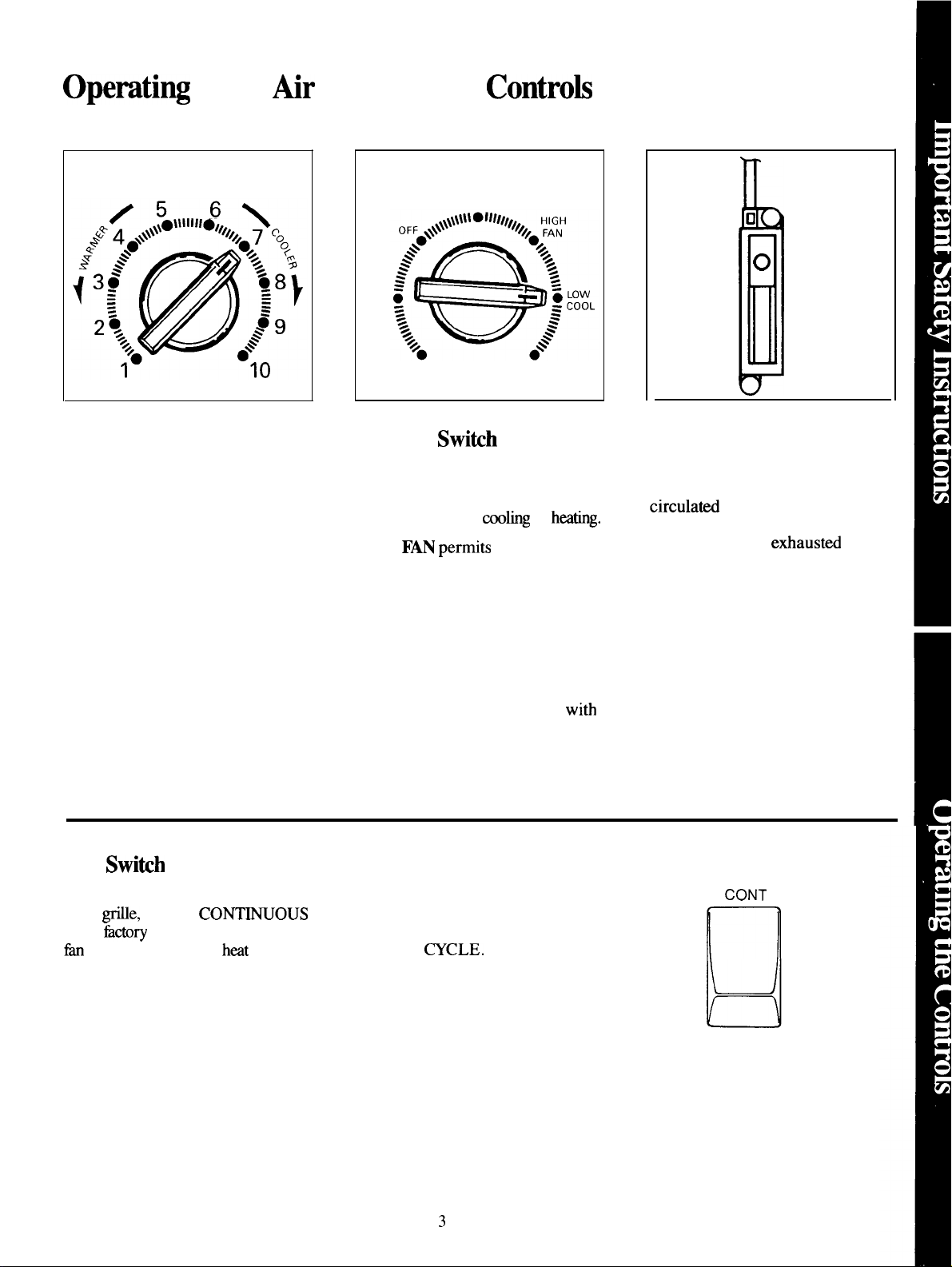
THERMOSTAT
Thermostat Control
When you turn this control to
the desired setting, the thermostat
will automatically control the
temperature of the indoor air.
The higher the number selected,
the cooler the indoor air will be.
The lower the number selected, the
warmer the indoor air will be.
SELECTOR
LOW
FAN
LOW
HEAT
HIGH HIGH
HEAT
COOL
Selector Switih
OFF
turns air conditioner off.
HIGH FAN
operation without
LOW
speed operation without cooling
or heating.
LOW COOL permits cooling with
low fan speed operation.
permits high fan speed
mbg
F~ permiw
low fan
or
hating.
n
VENT
o
CLOSE
OPEN
I
Ventilation Control
When this control is set at CLOSE,
only the air inside the room can be
circulati
it’s in the OPEN position, some
indoor air can be
the room.
and conditioned. When
etiausted
from
Fan Swikh
The Fan Switch, located behind the
front
@e,
is set at
at the tictory to provide continuous
h
operation in cool or
See how to remove the front grille
on page 6.
CON~OUS
h=t
modes.
HIGH COOL permits cooling
with high fan speed operation.
LOW HEAT permits heating
low fan speed operation.
HIGH HEAT permits heating with
high fan speed operation.
If you want the fan to cycle on and
off with the compressor or
resistance heater, set the Fan
Switch at
~CLE.
witi
FAN
CONT
n
CYCLE
3
Page 4
Opemtiq
Your Air Conditioner
Controk(~~.ti.~~)
For Normal Cooling
1. Set Selector Switch at HIGH
COOL.
2. Set Thermostat Control at
desti
number
is a good starting position). If room
temperature is not satisfactory after
a reasonable time, set the temperature
control at a higher number for a
cooler room or at a lower number
for a warmer room.
For
~imum
1. Set Selector Switch at HIGH
COOL.
2. Set Thermostat
3. Set Ventilation Control at
CLOSE position.
4. Shift Fan Switch to
CONTINUOUS.
(usdy
Cooling
Con~l
the midpoint
at 10.
For Quieter Operation
1.
Set Selector Switch at LOW
COOL.
2. Set Thermostat Control at
desired number.
3. Set Ventilation Control at
CLOSE position.
4. Shift Fan Switch to desired
position—CONTINUOUS or
~CLE.
For Nighttime Operation
During the cooler evening hours,
it is recommended that you set the
Selector Switch at LOW COOL for
very quiet operation and the
Thermostat Control at mid-range
(5
or
6).
When the Thermostat Control is set
on 9 or 10 and the Fan is set on low
speed, moisture may freeze on the
coils and prevent the unit from
cooling. If this happens, set the
Fan at high speed and set the
Thermostat Control to a lower
number.
For Etireme
For greatest economy and best
performance, we suggest you
always set the Selector Switch at
HIGH COOL in extremely hot
weather.
~mperatures
For air circulation and
filtering without cooling
or heating
Set Selector Switch at HIGH FAN
or LOW FAN.
For Ventilation
Whether controls are set for
heating or fan
Ventilation Control at OPEN lets
room air be exhausted to the
outside. This is helpful in removing
stale air, smoke or odors from the
room, and permits outdoor air to
enter through normal openings in the
house. However, cooling
is reduced when this control is set
at OPEN, so we suggest you don’t
keep it there long—especially in
hot, humid weather.
ody
operation, setting
coohg,
effmtiveness
For Normal Heating
1. Set Selector Switch at HIGH
HEAT.
2. Set Thermostat Control at
desired number
is a good starting position). If room
temperature is not satisfactory after
a-enable time, set the temperature
control at a lower number for a
warmer room or at a higher number
for a cooler room.
For
Mti
1. Set Selector Switch at HIGH
HEAT.
2. Set Thermostat Control at 1.
3. Set Ventilation Control at
CLOSE position.
4. Shift Fan Switch to
CONTINUOUS.
(us~y
the midpoint
urn Heating
4
Page 5
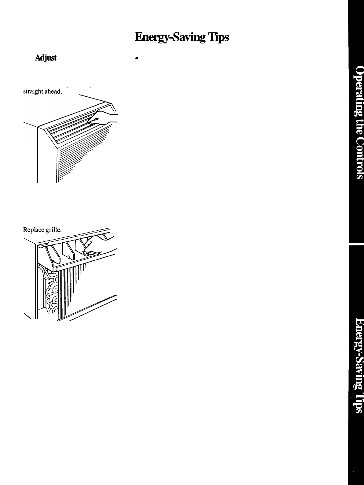
To
Mjti
Air Direction
Up-and-down air direction:
Adjust louvers with your fingertips
to direct discharged air
up,
down or
Side-to-side air direction:
Remove the front grille (see page 6),
Adjust louvers with your fingertips
to direct discharged air to the left,
to the right or straight ahead.
Repl
c
Keep the air filter clean. (See
instructions on page 6.)
●
For most efficient cooling, keep
vent in closed position except when
you want to exhaust air, smoke or
odors from the room.
●
Don’t let the room get too hot or
too cold. Whenever possible, turn
the unit on before the room heats
up or cools down.
●
Keep windows and doors
closed. Conditioned air escapes
when they’re open.
● Keep furnace floor registers and
cold air returns closed. Conditioned
air can easily escape through them.
●
Don’t block front of unit when it
is operating. Curtains or drapes
blocking it will restrict air flow.
●
It’s best to operate your air
conditioner at high speed during
extremely hot or cold weather.
●
\.
Keep outdoor condenser coil
clean. (See page 6.)
●
Turn air conditioner off before
vacations or extended absences
from home.
\
5
Page 6

Care and
Cleani~
USER
~EN~CE
~STRU~IONS
Turn air conditioner off and
remove the plug from the wall
outlet before cleaning.
Grille & Cabinet
Wipe both sides of grille with a
clean cloth lightly dampened with
mild liquid
or clean with a
brush. Be careful not to force the
movable louvers out of position.
Other areas behind the grille may
be wiped or vacuumed, taking care
not to damage the coil fins.
Wash cabinet with mild soap or
detergent and lukewarm water.
Never use strong chemicals,
solvenb or bleaching agenti.
dishwashing
vacuum
detergent,
cleaner
Condenser Coils
These coils on the weather side
of the unit should be checked
periodically and cleaned if clogged
with dirt or soot from the atmosphere.
If extremely soiled, they may need
to be steam
through your GE service outlet.
clmd,
a service
dable
Air
Hlter
The air filter behind the front grille
should be checked and cleaned at
least every 30 days or as
needs cleaning.
To remove the filter:
Grasp the tab at the air outlet on the
front grille and pull it straight up.
Clean the filter
cleaner to remove light dust. Wash
the filter in lukewarm, soapy water
and rinse in clear water to remove
sticky dust.
When replacing the filter, be sure
the word FRONT is facing you as
you slide the filter back into place.
with a vacuum
ofien
/
as it
~ont
Grille Removal
The front grille can be removed
for more thorough cleaning or to
make the model and serial numbers
accessible,
To remove the front grille:
1.
Grasp the bottom of the grille
and swing it toward you about 4
inches.
2. Slide the grille upward to free
the three
from slots in the top of the chassis.
To replace the grille, hook top of
grille onto top of chassis and push
bottom of grille in until it snaps
into place.
tibs
at the top of the grille
6
Page 7

-
m
---
UseThis ~oblem
-
Questions?
Solver
PROBLEM
AIR CONDITIONER
DOES
AIR CONDITIONER
COOL AS
OPERATING
SOUNDS
N~
OPERATE
“DOES NOT HEAT OR
~ SHO~D”
POSSIBLE CAUSE AND REMEDY
●
Not plugged in. Plug may have been bumped loose by vacuum cleaner or furniture.
●
If~lu~ed
●
Curtains, blinds or furniture blocking front of air conditioner
●
Thermostat Control may not be set high or low enough. Also, when Fan Switch
is at
CONTINUOUS. Turn knob to another number. Highest setting should provide
maximum cooling.
. Air filter dirty, should be cleaned at least every 30 days. See instructions on page 6.
. Room may have been very hot or cold when air conditioner was first turned on. Allow
time for it to cool down or warm up.
● Condition air maybe escaping through open furnace floor registers and cold air
returns.
●
Ventilation Control maybe set at OPEN, allowing outside air to enter room.
●
Cooling coils have iced up. To melt ice, set the Fan at high speed and the
Thermostat Control to a lower number.
●
Thermostat click, a metallic sound, maybe heard when compressor cycles on and off.
This is normal.
~CLE,
in,
fise
could have
the temperature in the room will vary more than when it’s at
blown
or circuit
bre~er
may have been tripped.
wfil
restrict airflow,
. Fan cycles on and off with compressor when Fan Switch behind front grille is
at
~CLE
continuously when air conditioner is on.
WATER
OUTSIDE
WATER
INSIDE
WATER IN BASE PAN
(ON OUTDOOR SIDE)
If you need more help.. call, toll free:
GE
800.626.2000
consumer information service
hswer
DWPPING
DWPPING
Center”
●
Excess water may overflow in extremely hot and humid weather. This is
●
Air conditioner must be installed level or tilted
disposal.
. This is normal for a short period in areas with little humidity; normal for a longer
period in very humid areas. Moisture removed from indoor air drains to rear of
cabinet where it is picked up by a fan and thrown against the outdoor condenser coil.
and Selector Switch is in cool or heat position. Otherwise, fan runs
norrnd.
slightiy
to the outside for proper water
7
Page 8

Instillation Instructions
~PORTANT: have
OWNER: Keep these
Electrical
Safety—
these instructions with the appliance.
i~ructions
MPO~~T...
Please Read Carefully.
How to connect electricity
For personal safety, this
appliance must be properly
grounded.
Electrical requirement
~-volt
volt a.c., 60 hz grounded outlet
protected with a 15 amp time delay
fuse or circuit breaker.
The power cord on these models has
a three-prong (grounding) plug that
mates with a standard three-prong
(grounding) wall outlet (Fig. 1) to
minimize the possibility of electric
shock hazard from these appliances.
PREFERRED
METHOO
Fig. 1
Where a standard two-prong wall
outlet is encountered, it is your
personal
to have it replaced with a properly
grounded three-prong wall outlet.
models require a
am
\ >, ,:
~ \
Vt
responsibfiity
h.
“
n
INSURE PROPER GROUND
EXISTS BEFORE USE
and obligation
115/120-
for future use.
230/208-volt models
own single branch circuit supplying
230/208-volt a.c., protected with a
time delay fuse or circuit breaker.
This is recommended for best
performance and to prevent
overloading house wiring circuits,
which could cause a possible fire
hazard from overheating wires.
The power cord on these models
has a 230/208-volt perpendicular,
tandem or large tandem type plug
that mates respectively with a
230/208-volt perpendicular,
tandem or large tandem type wall
outlet. These types of outlets are
available at most hardware stores.
require their
Q@
230/208-VOLT
PERPENDICULAR TYPE WALL OUTLET
LINE CORD PLUG
REQUIRES 20 AMP TIME DELAY FUSE
OR CIRCUIT BREAKER PROTECTION
@@
230/208-VOLT
TANDEM TYPE
CORO
LINE
PLUG
REQUIRES 15 AMP TIME DELAY FUSE
OR CIRCUIT BREAKER PROTECTION
MATCHING
MATCHING
WALL OUTLET
-0
mm
(.’
\
@
●
@o
230/208-VOLT
LARGE TANDEM TYPE WALL OUTLET
LINE CORD PLUG
REQUIRES 30 AMP TIME DELAY FUSE
OR CIRCUIT BREAKER PROTECTION
Whether your air conditioner is a
~-volt
is important to have the wall
outlet and circuit checked by a
qualified electrician if there is
any doubt as to whether a proper
ground exists.
or a 230/208-volt unit, it
MATCHING
DO
N~,
UNDER
C~CUMSTANC~, Cm
OR
REMO~ = T~
(GROUND) PRONG
T~
POWER CORD.
Am
~OM
———
8
Page 9

Use of adapter
(~-volt modek
pl~
only)
Because of potential safety hazards
under certain conditions, we
strongly recommend against use
of an adapter plug.
if you still
elect
However,
to use an adapter,
where local codes permit, a
TEMPORARY
CONNE~ION
may be made to a properly grounded
two-prong wall outlet by use of a
UL fisted-adapter (Fig. -2) available
at most local hardware stores.
TEMPORARY METHOD
(ADA~ER
PLUGS NW
PERMl~ED IN ~NADA)
ALIGN LARGE
PRONGS/SL~
&
The
larger
@m
slot in the
aligned-with the larger
~~J•tÁJ•dÂJ•
.
.
,-
adapter
must be
sl~t
in the wall
outlet to provide proper polarity in
the connection of the power cord.
CAUTION:
Attaching the adapter
ground terminal to wall outlet cover
screw does not ground the appliance
unless cover screw is
insulated, and
wdl outlet is
meti,
and not
groundd
through house wiring. You should
have the circuit checked by a qualified
electrician to make sure the outlet
is properly grounded.
men
disconnecting the power cord
from the
adapter with
ada~ter. always
~ne
hand. if this is not
hold the
done, the adapter ground terminal is
very likely to break with repeated use.
Should the adapter ground
terminal break, DO NOT USE the
appliance until a proper ground
has again been established.
Use of
e*nsion
cords
Because of potential safety
hazards under certain conditions,
we
stro@y
use of an extension cord.
recommend against the
However,
if you SW elect to use an extension
cord, it is absolutely necessary that
it be a
UL listed 3-wire grounding
type appliance extension cord and
that the current carrying rating of
the cord in amperes be equal to or
greater than the branch circuit size
shown on the rating nameplate of
the appliance.
9
Page 10

Window Mounting
0
~“..,
I
I <*, ‘ ~
I
1
1
1
I
1<
I‘Q ,, ‘ ‘
~.~’
\
.-
Q
Screws
N
.>
\\
\
/
Type A
(4)
\
‘r.
,L,
<
.%
0. ;
“(’”
\
\
4
\’
\
I
b
/
(w
\
0
\
0
0
/
/
models)
;01
/
0
0
0
/
/
I
I Stool Seal
1
Gasket
I
. . . . . . .
I
w,.::.,,:,,
I
+
1
/
. . -. . ., .
Type B
Screws (2)
s
Sill Sup~ort (2)
Adjusting—
Bolt (2)
Closure Panel
,(two
panels cut from
one piece provided)
Y
Spring Clips
)
e
A
Type
4
-Lock
(4)
acer
Nut (2)
Screws
+
(4)
(2)
Type
A
Qty-4
Type B
Qty-4
Type C
~ainted
Qty-6
Type D
Qty-4
Type E
Qty-4
Type F
Qty-4
T
i
T
f
T
T
Took
Needed
c
Phillips head screwdriver
● Adjustable wrench
. Wood saw
Q
Scissors or
hife
Window Requirement
●
Standard double-hung window
with actual opening width of
31“ to41“.
●
Clear, vertical opening of 17”
minimum from bottom of sash to
stool.
c
Stool offset (height between sill
and stool) must be less than
Note: All supporting parh should
be secured to
firm
wood,
masonry or metal.
10
172”.
~
wall
Page 11

1.
Repare
(MK models
shipped only with chassis and front
grille.)
1.
Remove chassis from cabinet.
2. Loosen the locking screw (A),
then turn the chassis locking plate
90° downward as shown.
the Chassis.
only–NJ models are
2. Mount the Rear Grille.
1.
While holding the grille at
angle, insert it into clips at the top of
th~case and push it toward the unit.
Keep slight upward pressure on the
grille until it fits flush with the
bottom of the cabinet.
Clip
a45°
Clip
4. Install the Sill
Type B
Screws (2)
Type A
Screws
Supper@.
(4)
e
Chassis
Locking Plate
MK
Models
3. Loosen the ground screw (B),
then remove the ground wire. Save
the ground wire for reinstallation
later.
I
1
-’”?~
Cabinet
4. Pull the bottom corners of the
chassis and slide it out from the
cabinet.
B
Ground Screw
o
,,, ..,,,..
. . . . . . .
. . . . . . .
. . . . . . . ~
. . . . . .
. . . . . . . . .
. . . . . . .
\
2. Secure the bottom of the grille
with 2 long grille screws provided
with the grille.
Note: The rear grille may be
installed from the room side with 2
short screws provided with the grille.
3.
1.
Measure and mark
the window sill to establish the
mounting position of your unit.
2. Mark the stool 12~’’totheleft
and right of the center of the window
opening. These are the centerlines
for the sill
3. Mark the stool 13~’’totieleft
and right of the center of the window
opening. These are the panel index
marks.
%-3
Eepare
SUDDOrtS.
0.
Type-F Screws
the Window.
.,
. . . . . . ..-. -.’’’’-’’”
‘-’’’”
. . ,.
.
Type E Screws
thecenterof
.......-.-~:.
.-”
,,
. . . . . . . .
..
. . . . . . .
~~~~~ ‘
..
m
1
w@
1. Assemble sill
supports. Do not
tighten spacer
mounting screws
at this time.
2. Place sill support assemblies on
window stool and select spacer
position that will place the spacer
near the outermost point on the sill.
Tighten screws.
or
mna)
3.
Install sill support assemblies by
locating “V” notch in sill support,
and aligning with sill support mark
on stool. Secure with 2 type F
screws (on each sill support) to rear
of stool. Then install 1
screw through one of the two sill
support holes and into the sill.
4. Adjust sill supports to be level or
1/8” pitch toward the outside by
adjusting bolt and tightening lock
nut. If the sill is wood, the large
washers, provided, should be used
between the bolt head and the sill.
R%MSIDE
‘Spacer (2)
-
-Lock
+
—Adjusting
$
, e Washer (2)
~pe
stool
Nut (2)
Bolt
B
/
i
Ill
(2)
11
(continued
natpage)
Page 12

Window Mounting
(continued)
(~Kmodels)
5. Instill Closure
1.
Measure from the edge of the
finek.
panel index mark to the inside of
the sash track.
(
‘A” ;
Centerline
“’’B’;’
2. Mark A & B dimensions on the
panel (position of notches mark
panels for identification) and cut.
1
●
●
m
1
3.
Assemble panels to angles with
3
~pe
I
1
I
I
1
I
!
1
1
1
1
I
1
1
1
1
I
1
I
I
I
I
C screws on each panel.
0
1
I
I
1
1
1
I
1
1
1
1
I
I
1
1
I
1
I
,
1
1
1
●
d
Panel A must be assembled to the
lefi
case angle and Panel B to the
right case angle.
Angle
Gasket
~ngle
!.
=
,
.
,.
Type C
Screws
4.
Remove paper backing from the
gasket and apply the gasket to the
6. Instill Cabinet
in Window.
edge of the pan and angle. Push
1.
pencil point through the gaskets to
locate holes in the angles.
Strip backing off stool seal
gasket and place adhesive side
down, with rear edge of gasket
5. Install 2 spring clips to the
on line with rear of stool.
outside edge of each panel, about
3“ from the top and bottom.
ring Clips
●
2. Carefully slide empty cabinet
into window until preselected holes
inside cabinet line up with holes in
cabinet angles. Pull lower sash
down behind top flange of closure
panel angles.
●
●
6.
Insert the tab at the bottom of the
closure panel assembly into the slot
in the sill support. Insert the outer
edge of the closure panel assembly
into the sash track, and squeeze
clips on the panel to fit in the sash
track.
til
Be sure cabinet is installed right
side up.
●
Be sure seal gasket and panel
gaskets remain in position and do
not roll with the case.
3. From inside the cabinet, install 2
~pe
A screws through each side of
the cabinet, through gaskets and
into holes in case angles.
1- .=. -
~
?ype
Screws
<
.
A
I
P&nel
@
.1
.
.
~
7. Repeat on opposite side.
4. Remove backing paper from
case top gasket and apply to top of
cabinet under sash gasket.
5. Position the sash gasket along
the top of the case and insert tabs in
the cabinet angles through the slots
in the gaskets.
12
Page 13

To
w
,/
Imtill
Chassis into Cabinet or Wall Sleeve...
6. Using scissors or a knife, cut
gasket neatly to window width on
each side. Ends of gaskets should
be flush with the sash trim.
7. Make sure gasket is positioned
correctly along the top of the
cabinet and the panels, and that the
rear flange extends out and under
the lower sash.
&
Make sure the lower sash is
tightly behind the tab of the cabinet
angles, and onto the rear flange of
the gasket. Then bend the sash
gasket downward to expose the tab
of the case angles and install 2
~pe
D screws through the case
angles and into the lower sash.
Adjust to give neat appearance and
tight seal.
1.
Slide the chassis into the
installed cabinet (provided with
AJK models) or wall sleeve
RAB36, RAB37
provided) designed for AJJ models.
Make sure that the tubing on the
unit is not touching the wall case
and that the wall case insulation is
secure.
2. Turn the chassis locking plate
90° upward and lock the chassis
with the plate.
or
RAB38
(not
Ground Wire on MK models,
disconnected when the chassis was
removed from the cabinet, must be
reconnected to the cabinet as
shown in step 3 under
Chassis
WHEN THE LINE CORD RUN
IS
THE UNIT,
reach the wall receptacle. (Excess
cord length may be stored in the
space just below the electrical
component box). Insert the line
cord under the clamp provided with
the unit.
TO
THE
on page 11.
LE~
extend enough cord to
Prepare the
SIDE OF
Panel Groove
9.
Install the sash locking bracket
using a Type E screw.
Sash Bracket
//”
,, :
‘“
w
10.
width and stuff it between the top
of the lower sash and glass panes of
the upper sash. The foam gasket
should be flush with the top of the
lower sash.
,,
~~Ü‹˜@d•àó••ðü•• æ••€ïÜ‹¤LG•
/“
,,,;
.,
.,,,
“>” ,m
Cut the sash gasket to window
1
f’
‘
~
,1’
~
Type E
Screw
1
—
,
AJK Models
3.
Secure the line cord to the base
pan with the clamp provided.
\
Chassis
-clamp
—
This step must be followed before
reinstalling the chassis locking
plate.
4. Mount the grille on the front of
the chassis by hooking the top of
the grille onto the top of the chassis
and pushing bottom of grille in
until it snaps into place.
Is
@;-
“
\
\\
*.-
—%—
‘“
!
13
-—
—
Page 14

14
Page 15

Wdll
.“. —. ..- - ..-—... . . . ,,
Be There
With the purchase of your new GE appliance, receive the
assurance that if you ever need information or
assis~nce
from GE, we’ll be there. Al you have to do is cdl—toll-free!
GEAnswer Center@
80~626.2000
In-Home
Repak
Service
800-GE-CARES
AGE Consumer Service professional
will provide expert repair service,
scheduled at a time that’s convenient
for you.
company-operated locations offer you
service today or tomorrow, or at your
convenience
weekdays,
days). Our factory trained technicians
know
so most repairs can be
one visit.
hlany GE
your appliance inside and out-
Consumer Service
(7:00
a.m. to
9:00
a.m. to
7:00
2:00
p.m. Satur-
handed
p.m.
in just
Service Contracts
800-626-2224
You can have the secure feeling that
GE Consumer Service will
here
after your warranty expires. Purchase a GE contract while your warranty is still in effect and you’ll receive
a substantial discount. With a
year contract, you’re assured of future
service at today’s prices.
still
be
multiple-
Whatever your question about any
maior appliance, GE Answer Cente@
.
inf’orrnation
help. Your cdl—and your question—
will be answered
courteously And you can
time. GE Answer
open 24 hours a day, 7 days a week.
Telecommunication Device for the Deaf
service is available to
prompdy and
cdl
CenteF
service is
GE
any
Patis andAccessories
800-626-2002
Individu* quflled
own
apphances can have needed
parts
or accessories sent
heir
home, free of shipping charge!
The GE
to over 47,000 parts.. and
Genuine Renewal Parts are
warranted. VISA,
Discover cards are accepted.
contained in this
dws
any user. Other servicing
should be
vice personnel. Caution must be
exercised, since improper servicing
may cause unsafe operation.
par~ system provides access
User maintenance instructions
intended to be performed by
refemd
to service their
directiy
to
dl
GE
filly
MasteKard
hooMet cover proce-
to
qutiled
and
genedy
ser-
For Customers
Special Needs...
80~62E2000
cdl
--- -- . . . . ,., ---- —-
Wtih
Upon request, GE will provide Braille
controls
and a brochure to assist in planning a
barrier-free kitchen for persons with
limited mobility
free of charge,
or speech who have access to a
or
to request information or service.
fc~r
a variety of
cdl
Consumers with impaired hearing
a conventional teletypewriter may
800-TDD-GMC (800-833-4322)
CJE applimces,
T(J
obtain
800.626.2000.
these
items,
TDD
Page 16

YOUR GE ROOM AIR CONDITIONER
WARRANTY
Save
proof of original purchase date such as your sales slip or cancelled check to establish warranty period.
WHAT IS COVERED
FULL ONE-YEAR WARRANTY
For one year from date of original
purchase, we will provide, free of
charge, parts and on-site service
labor to repair or replace
of
the
room air conditioner
fails because of a manufacturing
defect.
FULL FIVE-YEAR WARRANTY
For five years from the date of
original purchase, we will provide,
free of charge, parts and on-site by our authorized Customer
service labor to repair or replace
any
prt
of the
system
(the compressor, condenser,
evaporator and all connecting
tubing) that fails because of a
manufacturing defect.
kr
each of the above warranties:
Transportation expense to and
from a service shop and shop
service labor if required will be
free of charge.
saal~
any part
that
refrigerating
This warranty is extended to
the original purchaser and any
succeeding owner for products
purchased
states, Hawaii and Washington,
In Alaska the warranty is the same
except that it is LIMITED because you
must pay to ship the product to the
service shop or for the service
technician’s travel costs to your home.
All warranty service will be provided
by our Factory Service Centers or
servicers during normal working
hours.
Look in the White or Yellow Pages
of your telephone directory for
GENERAL ELECTRIC COMPANY,
GENERAL ELECTRIC FACTORY
SERVICE, GENERAL
HOTPOINT FACTORY SERVICE or
GENERAL ELECTRIC CUSTOMER
CARE@ SERVICE.
for use in the 48 mainland
ELECTRIC-
D.C.
Care@
WHAT IS NOT COVERED
s
Service trips to teach you how to
use the product.
Read your Use and Care material.
If you then have any questions is of improper cooling or heating
about operating the product,
please contact your dealer or our contact your dealer or installer.
Consumer Affairs office at the
address below, or call, toll free:
GE Answer
800.626.2000
consumer information service
may not apply to you. This warranty gives you specific legal rights, and you may also have other rights which vary from state to state.
CenteF
Some states do not allow the exclusion or limitation of incidental or consequential damages, so the above limitation or exclusion
To know what your legal rights are in your state, consult your local or state consumer affairs office or your state’s Attorney General.
If further help is needed concerning this warranty, write:
Manager—Consumer Affairs, GE Appliances, Louisville, KY 40225
● Improper installation. ● Failure of the product resulting from
If you have an installation
problem, or if the air conditioner
capacity for the intended use,
You are responsible for providing
adequate electrical connecting
facilities.
. Replacement of fuses or
resetting of circuit breakers.
. In commercial locations labor
necessa~
location where it is accessible for
service by an individual technician.
Warrantor: General Electric Company
to move the unit to a
modifications to the product or due to
unreasonable use including failure to
provide reasonable and necessary
maintenance.
. Failure due to corrosion on models
not corrosion-protected.
. Damage to the product caused
by improper power supply voltage,
accident, fire, floods or acts of God.
WARRANTOR IS
FOR CONSEQUENTIAL DAMAGES.
NOT
RESPONSIBLE
Pub.
10-90
CG
No.
49-7239
AJJ09D AJK06L
AJJ1OD
AJJ1lD
Printed
AJK08A
AJK1OD
on
Singapore
 Loading...