

Page 1

AGQ12
Safety Instructions . . . . . . . .2, 3
Operating Instructions
. . . . .4, 5
Care and Cleaning
Air Filter . . . . . . . . . . . . . . . . . .6
Grille and Case . . . . . . . . . . . . .6
Outdoor Coils . . . . . . . . . . . . . .6
Installation Instructions
Preparing to Install the
Air Conditioner . . . . . . . . . . . . .7
Through-the-Wall
Installation—Optional . . . . . . .13
Window Installation . . . . . . .8–12
Troubleshooting Tips . . . . . .14
Normal Operating Sounds . . .15
Consumer Support
Consumer Support . . . . . . . . .20
Product Registration . . . . .17, 18
Warranty . . . . . . . . . . . . . . . . .19
3828A21031M 49-7564 11-06 JR
Owner’s Manual and
Installation Instructions
Write the model and serial numbers here:
Model # __________________________
Serial # __________________________
Find these numbers on a label on the
side of the air conditioner.
Air Conditioners
Room
ge.com
Page 2
IMPORTANT SAFETY INFORMATION.
READ ALL INSTRUCTIONS BEFORE USING.
WARNING!
For your safety, the information in this manual must be followed to minimize the risk of fire, electric shock
or personal injury.
■ Use this appliance only for its intended
purpose as described in this Owner’s
Manual.
■ This air conditioner must be properly
installed in accordance with the Installation
Instructions before it is used.
■ Never unplug your air conditioner by pulling
on the power cord. Always grip plug firmly
and pull straight out from the receptacle.
■ Replace immediately all electric service
cords that have become frayed or otherwise
damaged. A damaged power supply cord
must be replaced with a new power supply
cord obtained from the manufacturer and
not repaired. Do not use a cord that shows
cracks or abrasion damage along its length
or at either the plug or connector end.
■ If the receptacle does not match the plug,
the receptacle must be changed out by a
qualified electrician.
■ Turn the unit OFF and unplug your air
conditioner before making any repairs
or cleaning.
NOTE: We strongly recommend that any servicing
be performed by a qualified individual.
■ For your safety…do not store or use
combustible materials, gasoline or other
flammable vapors or liquids in the vicinity
of this or any other appliance.
■ All air conditioners contain refrigerants,
which under federal law must be removed
prior to product disposal. If you are getting
rid of an old product with refrigerants, check
with the company handling disposal about
what to do.
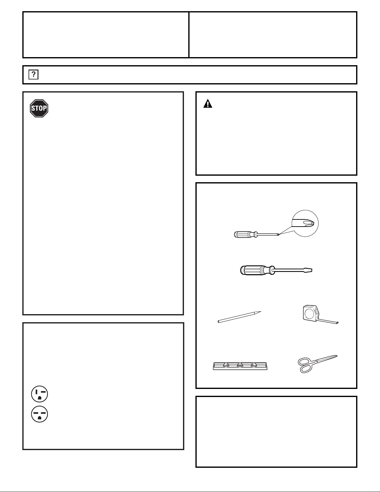
SAFETY PRECAUTIONS
Do not, under any circumstances, cut or remove
the third (ground) prong from the power cord. For
personal safety, this appliance must be properly
grounded.
DO NOT use an adapter plug with this appliance.
The power cord of this appliance is equipped
with a 3-prong (grounding) plug which mates
with a standard 3-prong (grounding) wall
outlet to minimize the possibility of electric
shock hazard from this appliance.
Power cord includes a current interrupter
device. A test and reset button is provided on
the plug case. The device should be tested on a
periodic basis by first pressing the TEST button
and then the RESET button. If the TEST button
does not trip or if the RESET button will not
stay engaged, discontinue use of the air
conditioner and contact a qualified
service technician.
Have the wall outlet and circuit checked by a
qualified electrician to make sure the outlet is
properly grounded.
Where a 2-prong wall outlet is encountered,
it is your personal responsibility and obligation
to have it replaced with a properly grounded
3-prong wall outlet.
The air conditioner should always be
plugged into its own individual electrical
outlet which has a voltage rating that matches
the rating plate.
This provides the best performance and also
prevents overloading house wiring circuits
which could cause a fire hazard from
overheated wires.
See the Installation Instructions, Electrical
Requirements section for specific electrical
connection requirements.
HOW TO CONNECT ELECTRICITY
Consumer Support Troubleshooting Tips
Operating Instructions Safety InstructionsInstallation Instructions
2
Page 3
3
Consumer SupportTroubleshooting Tips
Operating Instructions
Safety Instructions Installation Instructions
WARNING!
CAUTION:
DO NOT use an extension cord with any of the
230/208 volt models.
EXTENSION CORDS
READ AND FOLLOW THIS SAFETY INFORMATION CAREFULLY.
SAVE THESE INSTRUCTIONS
ge.com
Page 4
4
Consumer Support Troubleshooting Tips
Operating Instructions Safety InstructionsInstallation Instructions
■ To ensure proper operation, aim the remote
control at the signal receiver on the air
conditioner.
■ The remote control signal has a range of
up to 20 feet.
■ Make sure nothing is between the air conditioner
and the remote control that could block the
signal.
■ Make sure batteries are fresh and installed
correctly as indicated on the remote control.
About the controls on the air conditioner.
Features and appearance will vary.
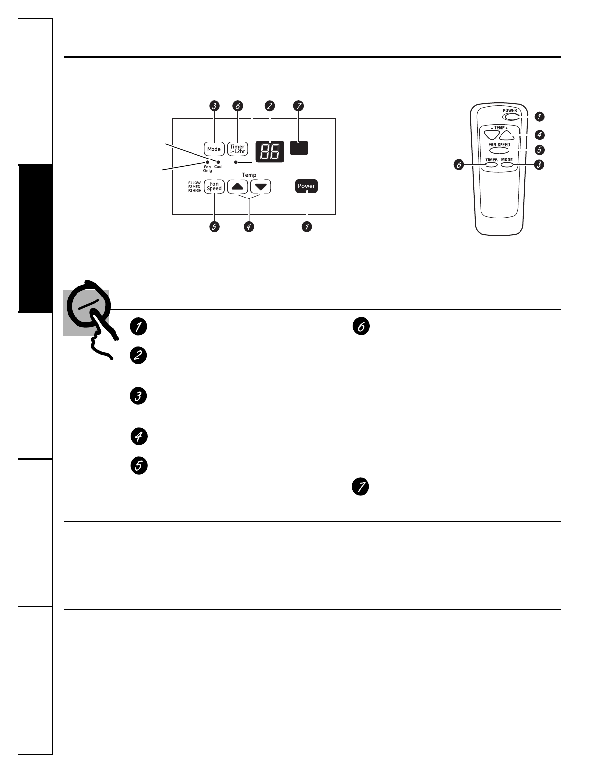
Air Conditioner Controls
Controls
ON/OFF Pad
Turns air conditioner on and off.
Display
Shows the set temperature or time remaining
on timer.
Mode
Use to set the air conditioner to Cool or
Fan mode.
Increase ▲ /Decrease ▼ Pads
Use to set temperature when in Cool mode.
Fan Speed Pad
Use to set the fan speed to LOW (F1), MED (F2)
or HIGH (F3).
Timer Pad
ON—When the air conditioner is off, it can be
set to automatically come on in 1 to 12 hours
at its previous setting. Each touch of the Tim er
pad or the INCREASE ▲ / DECREASE ▼ pads
will set the timer in hours.
OFF—When the air conditioner is on, it can
be set to automatically turn off in 1 to 12
hours. Each touch of the Tim er pad or the
INCREASE ▲ / DECREASE ▼ pads will set the
timer in hours.
To cancel the timer, press the Timer pad until
the display time disappears.
Remote Control Signal Receiver
Remote Control
This cool-only air conditioner was not designed for
freezing outdoor conditions. It must not be used in
freezing outdoor conditions.
Do Not Operate in Freezing Outdoor Conditions
Remote Control
Cool on
Fan
Only on
Timer on
Page 5
ge.com
Lights next to the touch pads on the air conditioner
control panel indicate the selected settings.
Cool Mode
Use the Cool mode with HIGH (F3), MED (F2) or
LOW (F1) fan for cooling. Use the INCREASE ▲ /
DECREASE ▼ pads to set the desired temperature
between 60°F and 86°F in 1°F increments.
An electronic thermostat is used to maintain the
room temperature. The compressor will cycle on
and off to keep the room at the set level of comfort.
Set the thermostat at a lower number and the indoor
air will become cooler. Set the thermostat at a higher
number and the indoor air will become warmer.
NOTE: If the air conditioner is off and is then turned on
while set to a Cool setting or if turned from a fan setting
to a Cool setting, it will take approximately 3 minutes
for the compressor to start and cooling to begin.
Cooling Descriptions
For Normal Cooling—Select the Cool mode and
HIGH (F3) or MED (F2) fan with a middle set
temperature.
For Maximum Cooling—Select the Cool mode
and HIGH (F3) fan with a lower set temperature.
For Quieter & Nighttime Cooling—Select the
Cool mode and LOW (F1) fan with a middle set
temperature.
NOTE: If you switch from a Cool setting to OFF or to a fan
setting, wait at least 3 minutes before switching back to a
Cool setting.
Fan Speed Mode
Use the fan at HIGH (F3), MED (F2) or LOW (F1) to
provide air circulation and filtering without cooling.
Since fan only settings do not provide cooling,
a temperature setting will not be displayed.
Consumer SupportTroubleshooting Tips
Operating InstructionsSafety Instructions Installation Instructions
Vent Control
The vent control is located above the control
panels.
When set at CLOSE, only the air inside the room
will be circulated and conditioned. When set at
OPEN, some inside air is exhausted outside.
To open the vent, pull the lever toward you.
To close it, push it in.
Air Direction—Side-to-Side
The side-to-side air direction is adjusted by moving
the lever to the left or right.
5
Air Direction—Up and Down
Fingertip pressure on the horizontal louvers
adjusts the air direction up or down.
In the case of a power outage or interruption, the
unit will automatically re-start in the settings last
used after the power is restored. If the Tim er
feature was set, it will resume its countdown.
You may need to set a new time if desired.
Power Outage Recovery Feature
Page 6

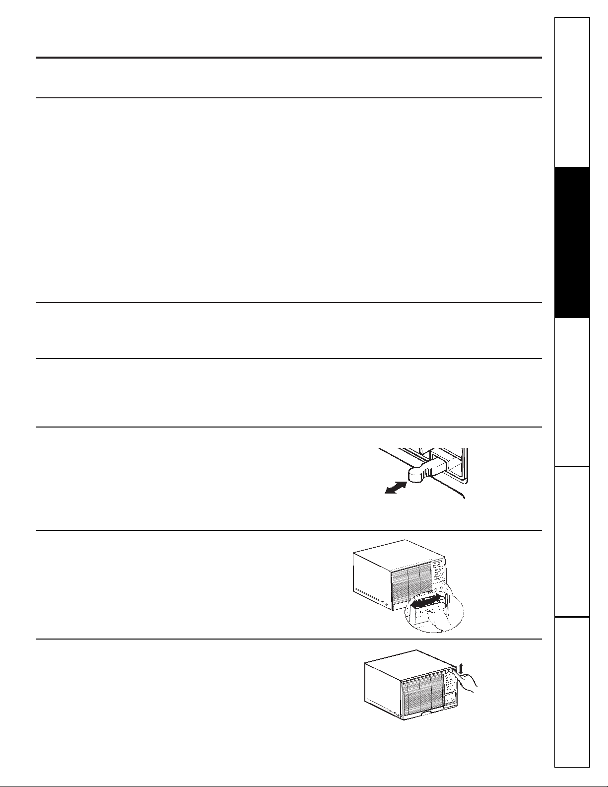
Air Filter
The air filter behind the front grille should be
checked and cleaned at least every 30 days or
more often if necessary.
To remove:
Open the inlet grille upward by pulling out the
bottom of the inlet grille.
Using the tab, pull up slightly on the filter
to release it and pull it down.
Clean the filter with warm, soapy water. Rinse and
let the filter dry before replacing it.
CAUTION: DO NOT operate the air
conditioner without a filter because dirt and lint will clog it
and reduce performance.
2
1
Outdoor Coils
The coils on the outdoor side of the air conditioner
should be checked regularly. If they are clogged
with dirt or soot, they may be professionally
cleaned.
Grille and Case
Turn the air conditioner off and remove the
plug from the wall outlet before cleaning.
To clean, use water and a mild detergent. Do not
use bleach or abrasives.
Care and cleaning of the air conditioner.
6
Consumer Support Troubleshooting Tips
Operating Instructions Safety InstructionsInstallation Instructions
Page 7
BEFORE YOU BEGIN
Read these instructions completely
and carefully.
•
IMPORTANT
— Save these
instructions for local inspector’s use.
•
IMPORTANT — Observe all
governing codes and ordinances.
• Note to Installer – Be sure to leave these
instructions with the Consumer.
• Note to Consumer – Keep these
instructions for future reference.
• Skill level – Installation of this appliance
requires basic mechanical skills.
• Completion time – Approximately 1 hour
• We recommend that two people install
this product.
• Proper installation is the responsibility
of the installer.
• Product failure due to improper installation
is not covered under the Warranty.
• You MUST use all supplied parts and use
proper installation procedures as described
in these instructions when installing this
air conditioner.
Questions? Call 800.GE.CARES (800.432.2737) or Visit our Website at: ge.com
Installation
Air Conditioner
Instructions
The 3-prong grounding plug minimizes the
possibility of electric shock hazard. If the wall
outlet you plan to use is only a 2-prong outlet,
it is your responsibility to have it replaced with
a properly grounded 3-prong wall outlet.
Some models require 230/208-volt a.c.,
protected with a time delay fuse or circuit
breaker. These models should be installed
on their own single branch circuit for
best performance and to prevent
overloading house or apartment wiring
circuits, which could cause a possible
fire hazard from overheating wires.
ELECTRICAL REQUIREMENTS
CAUTION:
Do not, under any circumstances, cut or
remove the third (ground) prong from the
power cord.
Do not change the plug on the power cord
of this air conditioner.
Aluminum house wiring may present special
problems—consult a qualified electrician.
7
TOOLS YOU WILL NEED
Phillips head screwdriver
Ruler or tape measurePencil
Level
Scissors or knife
Flat-blade screwdriver
Power cord includes a current interrupter
device. A test and reset button is provided on
the plug case. The device should be tested on a
periodic basis by first pressing the TEST button
and then the RESET button. If the TEST button
does not trip or if the RESET button will not stay
engaged, discontinue use of the air conditioner
and contact a qualified service technician.
Page 8
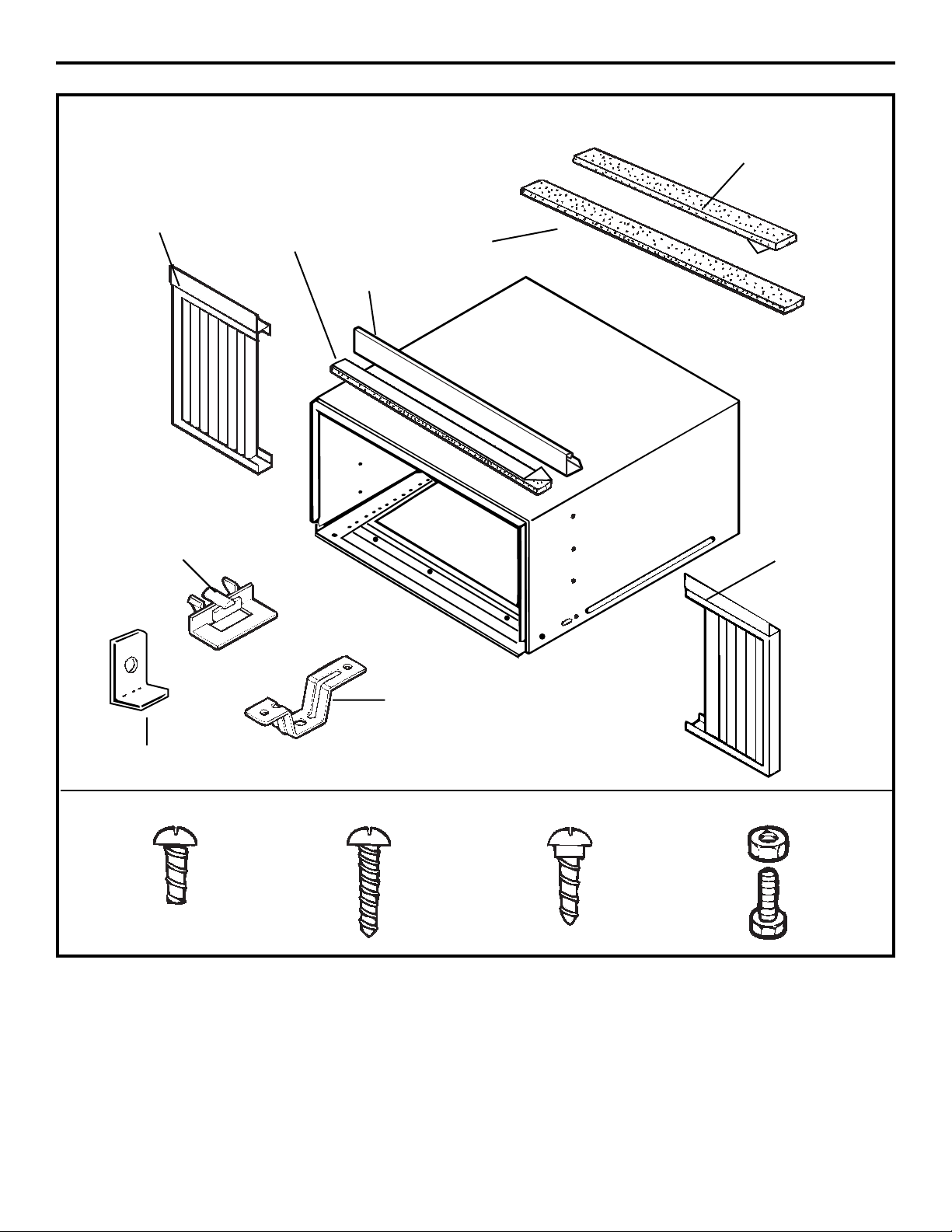
Type A (16)
Sill support (2)
Window locking
bracket
Frame guide (2)
Top
mounting
rail
Top
mounting
rail seal strip
Right
accordion
panel
Foam top
window gasket
Window
sash seal
Left
accordion
panel
Type B (3)
Type C (5)
Bolt (2)
Nut (2)
PARTS INCLUDED
(Appearance may vary)
8
Window Installation Instructions
Page 9
Window Installation Instructions
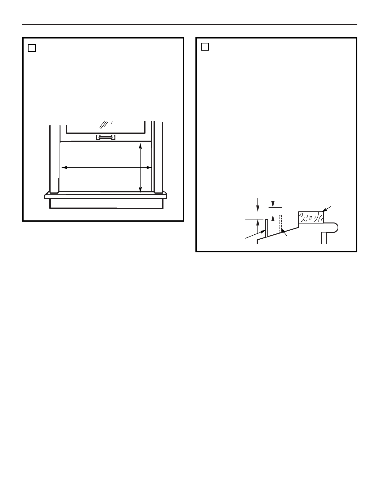
WINDOW REQUIREMENTS
• These instructions are for a standard
double-hung window. You will need to
modify them for other types of windows.
• All supporting parts must be secured
to firm wood, masonry or metal.
• The electrical outlet must be within
reach of the power cord.
1
16″ min.
27″ to 39″
(With accordion panels)
9
STORM WINDOW REQUIREMENTS
A storm window frame will not allow the
air conditioner to tilt toward the outside,
and will keep it from draining properly.
To adjust for this, attach a piece of wood
to the stool.
WOOD PIECES–
WIDTH: 2″
LENGTH: Long enough to fit inside the
window frame.
THICKNESS: To determine the thickness,
place a piece of wood on the stool to
make it 1/2″ higher than the top of the
storm window frame or the vinyl frame.
Attach securely with nails or screws
provided by the installer.
2
1/2″ higher
than storm
window
frame
Storm window
frame
Wood
Stool
1/2″ higher
than vinyl frame
(on some windows)
Vinyl frame
Page 10
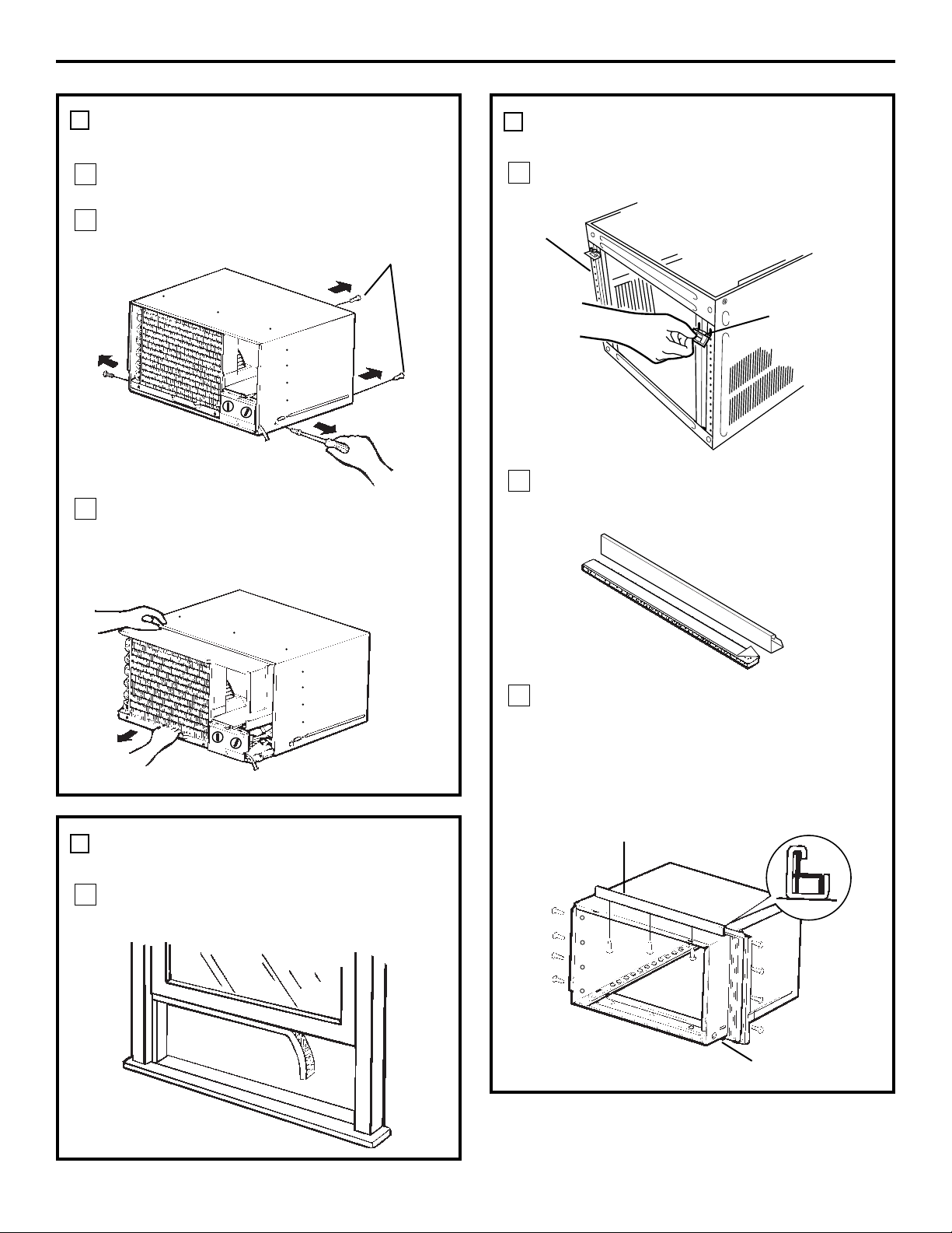
REMOVE THE AIR CONDITIONER
FROM THE CASE
Remove the 2 shipping screws from the
back of the case.
Remove the 2 screws on each side of the
case. Keep these for later use.
Slide the air conditioner from the case by
gripping the base pan handle and pulling
forward while bracing the case.
C
B
A
3
Shipping screws
PREPARE THE WINDOW AND
THE CASE (CONT.)
Carefully insert the plastic frame guides
into the bottom of the case on each side.
Remove the backing from the top mounting
rail seal strip and attach it to the bottom of
the top mounting rail.
Install the top mounting rail with 3 type A
screws on the inside of the case. Insert the
frames for the accordion panels into the top
mounting rail and the frame guides. Attach
the accordion panels to the side of the case
using 4 type A screws on each side.
D
C
B
4
Window Installation Instructions
PREPARE THE WINDOW AND
THE CASE
Cut the window sash seal to the proper
length. Peel off the backing and attach the
seal to the underside of the window sash.
A
4
Bottom of case
Frame guide
Top mounting rail
Frame guides
10
Page 11
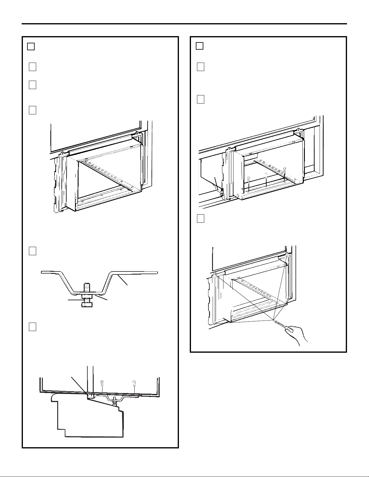
INSTALL THE CASE IN THE
WINDOW
Open the window and mark the centerline
of the window stool.
Carefully place the case on the window
stool and align the center mark on the
bottom front with the centerline of the stool.
Pull the window down behind the top
mounting rail.
NOTE: Do not shut the window so tightly that
movement of the accordion panels is
restricted.
Loosely assemble the sill supports.
Select the position that will place the sill
supports near the outermost point on the
sill. Attach the sill supports to the case track
hole in relation to the selected position
using 2 type A screws in each support.
E
D
C
B
A
5
Window Installation Instructions
Bolt Nut
Sill support
OUTDOORINDOOR
Frame guide
INSTALL THE CASE IN THE
WINDOW (CONT.)
Adjust the bolt and the nut in each support
so that the case is installed with a slight tilt
to the outside. Use a level; about 1/3 bubble
will be the correct case slant to the outside.
Secure the case to the window stool by
using 3 type B screws.
Pull the accordion panels to each window
sash track. Attach them on each side to the
window sash and the window stool using
4 type C screws.
H
G
F
Sill
support
11
5
Page 12
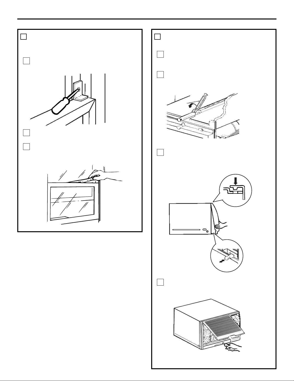
INSTALL THE AIR CONDITIONER
IN THE CASE
Slide the air conditioner into the case.
Reinstall the 2 screws removed earlier on
each side of the case.
Before installing the front grille, pull out the
vent control lever located above the unit
control knobs, as shown.
Attach the front grille to the case by inserting
the tabs on the grille into the slots on the
front of the case. Push the grille in until it
snaps into place.
Lift the inlet grille and secure the front frame
with a type A screw through the front grille.
Lower the inlet grille back into place.
Caulk or weather-strip any gaps or openings
to the outside to seal the installation.
D
C
B
A
Window Installation Instructions
INSTALL A SUPPORT BRACKET
AND THE FOAM TOP WINDOW
GASKET
Attach a support bracket with a Type C
screw.
Cut the foam top window gasket to the
window width.
Stuff the foam between the glass and the
window to prevent air and insects from
getting into the room.
C
B
A
6 7
Guide the lever carefully
through the grille as you
push it in.
12
Page 13

13
Through-the-Wall Installation Instructions—Optional
The case may be installed through-the-wall
in both existing and new construction.
Read completely, then follow step-by-step.
NOTE: Obtain all materials locally for
mounting the air conditioner throughthe-wall.
IMPORTANT
Through-the-wall installation is not
appropriate if any of the side or top louvers
in the case will be obstructed by the wall.
All side and top louvers in the case must
project on the outdoor side of the wall.
The room side of the case must project
into the room far enough to maximize the
balance of the unit.
The case must be installed level from sideto-side and with a slight tilt from front to
rear. Use a level; no more than a 1/2 bubble
will be the correct case slant to the outside.
Lintel angle is required to support bricks or
blocks above opening.
Flashing is required and should extend the
length of the opening to ensure no inside
cavity leakage occurs.
Remove the air conditioner from the case.
For specific instruction, refer to the Window
Installation Instructions.
Make certain that a wall receptacle is
available close to the hole location or make
arrangements to install a receptacle.
Place the case in the wall opening and
place wood support strips between the case
bottom and the flashing on both sides of the
bottom rail. They should be the same height
as the bottom rail and the same length as
the wall opening.
1
A
B
FINISH THE WALL OPENING
Caulk all four sides on the outdoor side of
the case to prevent moisture from getting
through to the interior wall. Use of flashing
(drip rail) will further prevent water from
dripping inside the wall and down the
outside of the building.
Place the air conditioner into the case.
For specific instruction, refer to the Window
Installation Instructions.
2
IMPORTANT (cont.)
Secure with 14 wood screws anchored at
least an inch into the wall support structure.
NOTE: Drill pilot holes, if necessary, for
proper installation. If the frame is oversized,
use shims to prevent case distortion.
1
D
A
B
Lintel angle
Plaster line
Trim molding
(if desired)
INSIDE
Bottom rail
Wood filler and
caulking (above
and below the
flashing)
Air louvers
(top and
sides must
project on the
outdoor side
of the wall)
OUTSIDE
Flashing
(Drip rail)
Case
bottom
Bottom
rail
Flashing
(Drip rail)
Wood support strips
Caulking
C
Page 14

Consumer Support Troubleshooting Tips
Operating Instructions Safety InstructionsInstallation Instructions
Problem Possible Causes What To Do
Air conditioner The air conditioner • Make sure the air conditioner plug is pushed completely
does not start is unplugged. into the outlet.
The fuse is blown/circuit • Check the house fuse/circuit breaker box and replace
breaker is tripped. the fuse or reset the breaker.
Power failure. • The unit will automatically re-start in the settings last
used after the power is restored.
• There is a protective time delay (approximately
3 minutes) to prevent tripping of the compressor
overload. For this reason, the unit may not start
normal cooling for 3 minutes after it is turned
back on.
The current interrupter • Press the RESET button located on the power cord plug.
device is tripped.
• If the RESET button will not stay engaged, discontinue
use of the air conditioner and contact a qualified service
technician.
Air conditioner does not Airflow is restricted. • Make sure there are no curtains, blinds or furniture
cool as it should blocking the front of the air conditioner.
The temp control may not • In Cool mode, press the DECREASE ▼pad.
be set correctly.
The air filter is dirty. • Clean the filter at least every 30 days.
See the Operating Instructions section.
The room may have been hot. • When the air conditioner is first turned on, you need to
allow time for the room to cool down.
Cold air is escaping. • Check for open furnace floor registers and cold air returns.
• Set the air conditioner’s vent to the closed position.
Cooling coils have iced up. • See “Air conditioner freezing up” below.
Air conditioner Ice blocks the air flow and • Set the controls at HIGH (F3) Fan or HIGH (F3) Cool and set
freezing up stops the air conditioner the thermostat to a higher temperature.
from cooling the room.
The remote control The batteries are inserted • Check the position of the batteries. They should be
is not working incorrectly. inserted in the opposite (+) and (–) direction.
The batteries may be dead. • Replace the batteries.
Water drips outside Excessively hot and • This is normal.
humid weather.
Water drips indoors The air conditioner is not • For proper water disposal, make sure the air conditioner
tilted to the outside. slants slightly from the case front to the rear.
Water collects in Moisture is removed from • This is normal for a short period in areas with little
base pan indoor air and drains into humidity; normal for a longer period in very humid areas.
rear of a cabinet where a fan
blows it against the outdoor
condenser coil.
Timer feature not A power outage or interruption • In the case of a power outage or interruption, the unit
working properly occurred. Tim er feature will reset to the original setting. You may
need to set a new time if desired.
Troubleshooting Tips.
Troubleshooting Tips. Save time and money! Review the chart below
first and you may not need to call for service.
14
Page 15

15
ge.com
Normal Operating Sounds
■ You may hear a pinging noise caused by water being
picked up and thrown against the condenser on rainy
days or when the humidity is high. This design feature
helps remove moisture and improve efficiency.
■ You may hear the thermostat click when the compressor
cycles on and off.
■ Water will collect in the base pan during high humidity
or on rainy days. The water may overflow and drip from
the outdoor side of the unit.
■ The fan may run even when the compressor does not.
Consumer SupportTroubleshooting Tips
Operating InstructionsSafety Instructions
Installation Instructions
Page 16

16
Consumer Support Troubleshooting Tips
Operating Instructions Safety InstructionsInstallation Instructions
Notes.
Page 17

17
General Electric Company
Warranty Registration Department
P.O. Box 32150
Louisville, KY 40232-2150
GE Service Protection Plus
™
GE, a name recognized worldwide for quality and dependability, offers you
Service Protection Plus
™
---comprehensive protection on all your appliances---
No Matter What Brand!
Benefits Include:
• Backed by GE
• All brands covered
• Unlimited service calls
• All parts and labor costs included
• No out-of-pocket expenses
• No hidden deductibles
• One 800 number to call
You will be completely satisfied with our service protection or you may request your money back
on the remaining value of your contract. No questions asked. It’s that simple.
Protect your refrigerator, dishwasher, washer and dryer, range, TV, VCR and much more---any brand!
Plus there’s no extra charge for emergency service and low monthly financing is available. Even icemaker
coverage and food spoilage protection is offered. You can rest easy, knowing that all your valuable
household products are protected against expensive repairs.
Place your confidence in GE and call us in the U.S. toll-free at 800.626.2224
for more information.
*All brands covered, up to 20 years old, in the continental U.S.
We’ll Cover Any Appliance.
Anywhere. Anytime.*
Please place in envelope and mail to:
✁
Cut here
Page 18

18
Consumer Product Ownership Registration
Important
Mail
Today!
First
Name
Mr. ■■ Ms. ■■ Mrs. ■■ Miss ■■
Street
Address
City
State
Date Placed
In Use
Month
Day
Year
Zip
Code
Apt. #
Last
Name
Phone
Number
_
_
Consumer Product Ownership Registration
Dear Customer:
Thank you for purchasing our product and thank you for placing your confidence in us.
We are proud to have you as a customer!
Follow these three steps to protect your new appliance investment:
Important: If you did not get a registration card with your
product, detach and return the form below to
ensure that your product is registered, or register
online at ge.com.
1
23
Model Number Serial Number
✁
Cut here
Complete and mail
your Consumer
Product Ownership
Registration today.
Have the peace of
mind of knowing we
can contact you in
the unlikely event of
a
safety modification.
After mailing the
registration below,
store this document
in a safe place. It
contains information
you will need should
you require service.
Our service number is
800.GE.CARES
(800.432.2737).
Read your Owner’s
Manual carefully.
It will help you
operate your new
appliance properly.
Model Number Serial Number
E-mail Address*
* Please provide your e-mail address to receive, via e-mail, discounts, special offers and other
important communications from GE Appliances (GEA).
■■ Check here if you do not want to receive communications from GEA’s carefully selected
partners.
FAILURE TO COMPLETE AND RETURN THIS CARD DOES NOT DIMINISH YOUR
WARRANTY RIGHTS.
For information about GEA’s privacy and data usage policy, go to ge.com and click on “Privacy
Policy” or call 800.626.2224.
GE Consumer & Industrial
Appliances
General Electric Company
Louisville, KY 40225
ge.com
Page 19

19
Consumer SupportTroubleshooting Tips
Operating InstructionsSafety Instructions
Installation Instructions
GE Air Conditioner Warranty.
For The Period Of: GE Will Replace:
One Year Any part of the air conditioner which fails due to a defect in materials or workmanship.
From the date of the During this limited one-year warranty, GE will also provide, free of charge, all labor and related
original purchase service to replace the defective part.
■ Service trips to your home to teach you how to
use the product.
■ Improper installation, delivery or maintenance. If you
have an installation problem, or if the air conditioner
is of improper cooling capacity for the intended use,
contact your dealer or installer. You are responsible
for providing adequate electrical connecting facilities.
■ Failure of the product resulting from modifications to
the product or due to unreasonable use including failure
to provide reasonable and necessary maintenance.
■ In commercial locations labor necessary to move the
unit to a location where it is accessible for service
by an individual technician.
■ Replacement of house fuses or resetting of circuit
breakers.
■ Failure due to corrosion on models not corrosion-
protected.
■ Damage to the product caused by improper power supply
voltage, accident, fire, floods or acts of God.
■ Incidental or consequential damage caused by possible
defects with this air conditioner.
■ Damage caused after delivery.
■ Product not accessible to provide required service.
What Is Not Covered:
This warranty is extended to the original purchaser and any succeeding owner for products purchased for home
use within the USA. If the product is located in an area where service by a GE Authorized Servicer is not available,
you may be responsible for a trip charge or you may be required to bring the product to an Authorized GE Service
location for service. In Alaska, the warranty excludes the cost of shipping or service calls to your home.
Some states do not allow the exclusion or limitation of incidental or consequential damages. This warranty gives
you specific legal rights, and you may also have other rights which vary from state to state. To know what your
legal rights are, consult your local or state consumer affairs office or your state’s Attorney General.
Warrantor: General Electric Company. Louisville, KY 40225
All warranty service provided by our Factory Service Centers,
or an authorized Customer Care
®
technician. To schedule service,
on-line, 24 hours a day, visit us at ge.com, or call 800.GE.CARES
(800.432.2737). Please have serial number and model number
available when calling for service.
Staple your receipt here.
Proof of the original purchase
date is needed to obtain service
under the warranty.
EXCLUSION OF IMPLIED WARRANTIES—Your sole and exclusive remedy is product repair as provided in this
Limited Warranty. Any implied warranties, including the implied warranties of merchantability or fitness for a
particular purpose, are limited to one year or the shortest period allowed by law.
Page 20

Consumer Support.
GE Appliances Website
ge.com
Have a question or need assistance with your appliance? Try the GE Appliances Website 24 hours a day,
any day of the year! For greater convenience and faster service, you can now download Owner’s Manuals,
order parts or even schedule service on-line.
Schedule Service ge.com
Expert GE repair service is only one step away from your door. Get on-line and schedule your service at
your convenience 24 hours any day of the year! Or call 800.GE.CARES (800.432.2737) during normal
business hours.
Real Life Design Studio ge.com
GE supports the Universal Design concept---products, services and environments that can be used by
people of all ages, sizes and capabilities. We recognize the need to design for a wide range of physical and
mental abilities and impairments. For details of GE’s Universal Design applications, including kitchen
design ideas for people with disabilities, check out our Website today. For the hearing impaired, please call
800.TDD.GEAC (800.833.4322).
Extended Warranties ge.com
Purchase a GE extended warranty and learn about special discounts that are available while your warranty
is still in effect. You can purchase it on-line anytime, or call 800.626.2224 during normal business hours.
GE Consumer Home Services will still be there after your warranty expires.
Parts and Accessories ge.com
Individuals qualified to service their own appliances can have parts or accessories sent directly to their
homes (VISA, MasterCard and Discover cards are accepted). Order on-line today, 24 hours every day
or by phone at 800.626.2002 during normal business hours.
Instructions contained in this manual cover procedures to be performed by any user. Other servicing generally
should be referred to qualified service personnel. Caution must be exercised, since improper servicing may cause
unsafe operation.
Contact Us ge.com
If you are not satisfied with the service you receive from GE, contact us on our Website with all the details
including your phone number, or write to: General Manager, Customer Relations
GE Appliances, Appliance Park
Louisville, KY 40225
Register Your Appliance ge.com
Register your new appliance on-line----at your convenience! Timely product registration will allow for
enhanced communication and prompt service under the terms of your warranty, should the need arise.
You may also mail in the pre-printed registration card included in the packing material.
20
Printed in China
Page 21

Instrucciones de seguridad . . .2, 3
Instrucciones de operación . . .4, 5
Cuidado y limpieza
Bobinas para exteriores . . . . . . . .6
Filtro de aire . . . . . . . . . . . . . . . . .6
Rejilla y caja . . . . . . . . . . . . . . . . .6
Instrucciones de instalación
Instalación a través
de la pared—opcional . . . . .13, 14
Instalación en ventanas . . . . .8–12
Preparándose para instalar
el acondicionador de aire . . . . . .7
Solucionar problemas . . . .15–16
Sonidos normales
de operación . . . . . . . . . . . . . . .16
Apoyo al consumidor
Apoyo al consumidor . . . . . . . .20
Garantía . . . . . . . . . . . . . . . . . . .19
Escriba los números de modelo
y serie aquí:
# de Modelo ___________________
# de Serie _____________________
Puede encontrar estos números
en una etiqueta en el costado del
acondicionador de aire.
Manual del propietario e
Instrucciones de Instalación
Acondicionadores de Aire
ge.com
AGQ12
3828A21031M 49-7564 11-06 JR
Page 22

2
INFORMACIÓN IMPORTANTE DE SEGURIDAD.
LEA TODAS LAS INSTRUCCIONES ANTES DE USAR.
¡ADVERTENCIA!
Por su seguridad, se debe seguir la información en este manual para minimizar el riesgo de incendios,
descargas eléctricas o lesiones personales.
■ Use este electrodoméstico solamente para
el propósito determinado según se describe
en el Manual del propietario.
■ Este acondicionador de aire debe instalarse
correctamente de acuerdo con las
Instrucciones de instalación antes de su uso.
■ Nunca desenchufe su acondicionador de
aire tirando del cable eléctrico. Siempre
agarre firmemente el enchufe y tire de
él directamente hacia afuera.
■ Reemplace inmediatamente todos los
cables eléctricos que se hayan pelado o que
se hayan dañado de alguna otra manera.
Un cable de corriente dañado no debe
repararse, sino que debe ser sustituido por
uno nuevo que se adquiera del fabricante.
No use un cable eléctrico que muestre
evidencias de deterioro, o daños de abrasión
en su superficie en alguno de sus extremos.
■ Si el receptáculo no coincide con el
enchufe, un electricista calificado debe
reemplazar el receptáculo.
■ Apague la unidad y desenchufe
su acondicionador de aire antes de hacer
cualquier reparación o limpiar.
NOTA: Recomendamos enérgicamente que cualquier
servicio llevado a cabo en este equipo lo realice un
individuo calificado.
■ Por su seguridad… no almacene ni use
materiales combustibles, gasolina u otros
vapores o líquidos inflamables en la
proximidad de éste o algún otro
electrodoméstico.
■ Todos los acondicionadores de aire
contiene refrigerantes, los que por Ley
Federan deben ser removidos antes de
desecharlos. Si usted planea deshacerse de
algún producto que contenga refrigerantes,
póngase en contacto con la compañía que
se encarga de recoger su basura para que le
indiquen qué hacer.
PRECAUCIONES DE SEGURIDAD
Bajo ninguna circunstancia, corte o remueva la
tercera púa (tierra) del cable eléctrico. En pos
de la seguridad personal, este electrodoméstico
debe siempre conectarse a tierra.
NO use un enchufe adaptador con este
electrodoméstico.
El cable eléctrico de este electrodoméstico está
equipado con un enchufe de tres púas (tierra)
que combina con un tomacorriente estándar
de tres tomas de pared para minimizar la
posibilidad de una descarga eléctrica.
El cable de alimentación incluye un
dispositivo para interrupción de corriente.
Se incluye un botón de prueba y de reinicio
en el dispositivo. El dispositivo debe ponerse
a prueba periódicamente: primero se presiona
el botón de TEST (prueba) y luego RESET
(reinicio). Si el botón TEST no se dispara
o si el botón RESET no queda enganchado,
deje de utilizar el acondicionador de aire y
comuníquese con un técnico calificado.
Pida a un técnico que inspeccione el
tomacorriente y el circuito para cerciorarse
de que el tomacorriente está conectado a
tierra de la manera apropiada.
Donde exista un tomacorriente de dos tomas,
es su responsabilidad y obligación personal
hacer que dicho tomacorriente sea
reemplazado por uno de tres tomas con
conexión a tierra.
El acondicionador de aire debería siempre
estar conectado a un tomacorriente individual
con su circuito de voltaje correspondiente.
Esto proporciona el mayor rendimiento y
además evita que los circuitos del resto de
la casa se sobrecarguen, lo cual podría causar
incendios por el sobrecalentamiento
del cableado.
Ver las Instrucciones de instalación, en la
sección Requisitos Eléctricos para los requisitos
específicos de conexión.
CÓMO CONECTAR LA ELECTRICIDAD
Apoyo al consumidor
Solucionar problemas
Operación SeguridadInstalación
Page 23

3
Apoyo al consumidor
Solucionar problemasOperaciónSeguridad Instalación
ge.com
¡ADVERTENCIA!
PRECAUCIÓN:
NO USE un cable de extensión con ninguno
de los modelos de 230/208 voltios.
CABLES DE EXTENSIÓN
LEA Y SIGA ESTAS INSTRUCCIONES DE SEGURIDAD CUIDADOSAMENTE.
GUARDE ESTAS INSTRUCCIONES
Page 24

4
■ Para garantizar una operación apropiada, oriente
el control remoto hacia el receptor de señal del
acondicionador de aire.
■ El receptor de señal tiene un rango máximo de
20 pies.
■ Cerciórese de que no haya nada entre el
acondicionador de aire y el control remoto que
pueda bloquear la señal.
■ Cerciórese de que las baterías sean frescas y se
instalen correctamente según se indica en el
control remoto.
Acerca de los controles en el acondicionador de aire.
Las funciones y el aspecto pueden variar.
Controles del acondicionador de aire
Controles
ON/OFF (ENCENDIDO/APAGADO)
Apaga y prende el acondicionador de aire.
Pantalla
Muestra la temperatura ajustada o el tiempo
restante en el sincronizador.
Modo
Usado para ajustar el acondicionador de aire
al modo Cool (Frío) o Fan (Ventilador).
Teclas de Increase ▲ (Aumentar)
/
Decrease
▼ (Reducir)
Usado para ajustar la temperatura cuando se
encuentre en el modo Cool (Frío).
Fan Speed (Velocidad de ventilador)
Usado para ajustar la velocidad del ventilador a
LOW (F1) (BAJO), MED (F2) o HIGH (F3) (ALTO).
Timer (Sincronizador)
ON (ENCENDIDO)—Cuando el acondicionador
de aire está apagado, puede ajustarse para que
se encienda automáticamente dentro de 1 a 12
horas en el nivel previo. Cada toque de la tecla
Timer (Sincronizador) o teclas de
INCREASE ▲
(AUMENTAR)/ DECREASE ▼ (REDUCIR) ajustará
el tiempo en horas.
OFF (APAGADO)—Cuando el acondicionador de
aire está encendido, puede ajustarse para que se
apague automáticamente dentro de 1 a 12 horas.
Cada toque de la tecla Timer (Sincronizador) o
teclas de
INCREASE ▲ (AUMENTAR)/ DECREASE
▼ (REDUCIR) ajustará el tiempo en horas.
Para cancelar el sincronizador, presione la tecla
Timer (Sincronizador) hasta que el tiempo en la
pantalla desaparezca.
Receptor de la señal del control remoto
Control remoto
Control remoto
Apoyo al consumidor
Solucionar problemas
Operación SeguridadInstalación
Enfriamiento
encendido
Ventilador
solamente
encendido
Sincronizador encendido
Este acondicionador de aire no es diseñado para
usar en temperaturas externas debajo el punto de
congelación. No use en las condiciones externas
debajo el punto de congelación.
No use en las condiciones externas debajo el punto de congelación
Page 25

ge.com
Las luces al lado de las teclas de toque en el panel de control del acondicionador de aire indicarán
los ajustes seleccionados.
Modo Cool (Frío)
Use el modo Cool con ventilador HIGH (F3) (ALTO),
MED (F2) (MEDIO) o LOW (F1) (BAJO) para enfriar. Use
las teclas de INCREASE ▲ (AUMENTAR)/ DECREASE ▼
(REDUCIR) para ajustar a la temperatura deseada
entre 60ºF y 86ºF en incrementos de 1ºF.
Se usa un termostato electrónico para mantener la
temperatura de la habitación. El compresor hará
ciclo entre apagado y encendido para mantener
la habitación a la temperatura deseada. Ajuste el
termostato a un número menor y el aire interno
se enfriará más. Si lo ajusta a un número mayor,
la temperatura del aire interno se calentará más.
NOTA: Si el acondicionador de aire está apagado y luego
se enciende mientras está ajustado en un ajuste Cool (Frío)
o si se cambia de un ajuste de ventilador a uno de Cool
(Frío), tomará aproximadamente 3 minutos para que el
compresor comience a enfriar otra vez.
Descripciones de enfriamiento
Para enfriamiento normal—Seleccione el modo de
ventilador Cool (Frío) y HIGH (F3) (ALTO) o MED (F2)
(MEDIO) con una temperatura de ajuste media.
Para enfriamiento máximo—Seleccione el modo
de ventilador Cool y HIGH F3 (ALTO) con una
temperatura de ajuste menor.
Para enfriamiento silencioso y enfriamiento nocturno—
Seleccione el modo de ventilador Cool y LOW (F1)
(BAJO) con una temperatura de ajuste media.
NOTA: Si cambia de un ajuste Cool (Frío) a OFF
(APAGADO) o a un ajuste de ventilador, espere
aproximadamente 3 minutos antes de cambiar otra
vez al ajuste de Cool (Frío).
Modo de Fan Speed (Velocidad de ventilador)
Use el ventilador en HIGH (F3) (ALTO), MED (F2)
(MEDIO) o LOW (F1) (BAJO) para proporcionar
circulación de aire y filtración sin enfriamiento.
Debido a que los niveles de ventilador únicamente
no proporcionan enfriamiento, el nivel de
temperatura no se muestra en la pantalla.
Control de la ventilación
El control de ventilación está localizado encima de
los paneles de control.
Cuando está ajustado en CLOSE (CERRADO),
solamente el aire en el interior de la habitación
circulará y se acondicionará. Cuando está ajustado
en OPEN (ABIERTO), un poco del aire interno es
expelido hacia afuera.
Para abrir la rejilla, tire de la palanca hacia
usted. Para cerrarla, empújela hacia adentro.
Dirección del aire—de lado a lado
La dirección de lado a lado del aire es ajustada
moviendo la palanca hacia la derecha o izquierda.
5
Dirección del aire—hacia arriba y hacia abajo
Apoyo al consumidor
Solucionar problemasOperaciónSeguridad Instalación
Una presión sencilla con los dedos en las parrillas
horizontales ajustará la dirección del aire hacia
arriba o hacia abajo.
En caso de la pérdida de la energía o interrupción,
la unidad reiniciará automáticamente en las
funciones de la última vez que fue usado una
vez la energía sea restablecida. Si la función del
Sincronizador estaba definida, continuará la cuenta
regresiva. Es posible que usted necesite ajustar un
tiempo nuevo si así lo desea.
Función de recuperación de pérdida de energía
Page 26

Filtro de aire
El filtro de aire detrás de la rejilla frontal debe
inspeccionarse y limpiarse por lo menos cada
30 días o más a menudo si fuese necesario.
Para retirarlo:
Abra la parrilla de entrada hacia arriba
tirando de la misma desde el fondo.
Usando la orejilla, tire hacia arriba
ligeramente sobre el filtro para liberarlo
y extráigalo.
Limpie el filtro con agua tibia y jabón. Enjuáguelo y
permita que se seque antes de colocarlo otra vez en
su lugar.
PRECAUCIÓN: NO OPERE el
acondicionador de aire sin el filtro debido a que la suciedad y
las pelusas lo obstruirán y reducirán su rendimiento.
2
1
Bobinas para exteriores
Se deben inspeccionar con frecuencia las bobinas
en el lado exterior del acondicionador de aire. Si
las mismas están obstruidas con suciedad u hollín,
podrían limpiarse profesionalmente.
Rejilla y caja
Apague el acondicionador de aire y retire el
enchufe del tomacorriente de la pared antes
de limpiar.
Para limpiar, use agua y un detergente suave.
No use cloro o materiales abrasivos.
Cuidado y limpieza del acondicionador de aire.
6
Apoyo al consumidor
Solucionar problemas
Operación SeguridadInstalación
Page 27

7
¿Preguntas? Llame 800.GE.CARES (800.432.2737) o Visite nuestra página en la red en: ge.com
Instrucciones
Acondicionador
de instalación
de aire
El enchufe de tres púas con conexión a tierra
minimiza la posibilidad de descargas eléctricas.
Si el tomacorriente de la pared que usted planea
usar solamente tiene 2 tomas, es su
responsabilidad hacer que un técnico lo
reemplace por uno de tres tomas con conexión
a tierra.
Algunos modelos requieren 230/208
voltios, de corriente alterna, protegidos
por un fusible de dilatación de tiempo
o un cortacircuitos. Estos modelos
deberían instalarse en un ramal
exclusivo del circuito para un
rendimiento más notable y para prevenir
sobrecargas en los circuitos de
cableados de su casa o apartamento,
lo cual podría representar un riesgo
de incendio por el sobrecalentamiento
de los alambres.
REQUISITOS ELÉCTRICOS
PRECAUCIÓN:
Bajo ninguna circunstancia corte o remueva
la tercera púa (conexión a tierra) del cable
eléctrico.
No cambie el enchufe en el cable eléctrico
de este acondicionador de aire.
Los cables caseros de aluminio podrían
presentar problemas especiales. Consulte
a un técnico electricista calificado.
ANTES DE INICIAR
Lea estas instrucciones completa y
cuidadosamente
•
IMPORTANTE — Guarde estas
instrucciones para uso del inspector local.
•
IMPORTANTE
— Observe todos
los códigos y órdenes de ley.
• Nota al instalador – Asegúrese de dejar
estas instrucciones con el consumidor.
• Nota al consumidor – Conserve estas
instrucciones para referencia futura.
• Nivel de destreza – La instalación de este
aparato requiere de destrezas mecánicas
básicas.
• Tiempo de ejecución – Aprox. 1 hora
• Recomendamos dos personas para
la instalación de este producto.
• La instalación apropiada es la
responsabilidad del instalador.
• La falla del producto debido a una
instalación inadecuada no está cubierta
por la garantía.
• Cuando instale este acondicionador
de aire, DEBE usar todas las piezas
suministradas y usar procedimientos
adecuados de instalación.
El cable de alimentación incluye un
dispositivo para interrupción de corriente. Se
incluye un botón de prueba y de reinicio en el
dispositivo. El dispositivo debe ponerse a prueba
periódicamente: primero se presiona el botón de
TEST (prueba) y luego RESET (reinicio). Si el
botón TEST no se dispara o si el botón RESET
no queda enganchado, deje de utilizar el
acondicionador de aire y comuníquese
con un técnico calificado.
Page 28

Tipo A (16)
Soporte del
umbral (2)
Soporte de cierre
de la ventana
Guía del marco (2)
Riel de
montaje
superior
Cinta de sellado
del riel de
montaje superior
Panel de
acordeón
derecho
Parte superior de la
espuma de la junta
de la ventana
Banda de sello
de la ventana
Panel de
acordeón
izquierdo
Tipo B (3)
Tipo C (5)
Tornillo (2)
Tuerca (2)
PARTES INCLUIDAS
(apariencia puede variar)
Instrucciones de instalación en una ventana
8
HERRAMIENTAS QUE NECESITARÁ
Un destornillador de estrella
Una regla o cinta métrica
Lápiz
Nivel
Tijeras o cuchilla
Un destornillador
con hoja plana
Page 29

Instrucciones de instalación en una ventana
REQUISITOS PARA LA VENTANA
• Estas instrucciones son para una
ventana estándar de dos pliegues.
Usted necesitará modificar el proceso
para otros tipos de ventanas.
• Todas las partes de apoyo deben quedar
totalmente aseguradas a algún metal,
mampostería o a la madera.
• El tomacorriente eléctrico debe estar al
alcance del cable eléctrico del
acondicionador de aire.
1
16″ mín.
27″ a 39″
(con paneles de acordeón)
9
REQUISITOS DE UNA VENTANA
DE TORMENTAS
Un marco de ventana de tormentas no
permitirá que el acondicionador de aire se
incline hacia el exterior y evitará que drene
apropiadamente. Para solucionar este problema,
adhiera un pedazo de madera a la repisa.
PEDAZOS DE MADERA–
ANCHO: 2″
LONGITUD: Lo suficientemente largo
como para ajustar en el interior del marco
de la ventana.
GRUESO: Para determinar el grueso, coloque
un pedazo de madera en la repisa para
hacerla 1/2″ más alta que la parte superior
del marco de la ventana de tormentas o del
marco vinilo.
Péguelo firmemente con clavos o con
tornillos proporcionados por el instalador.
1/2″ más alto
que el marco
de ventana
de tormentas
Marco de
ventana de
tormentas
Repisa
2
1/2″ mas alto que el
marco vinilo (en algunas
ventanas)
Marco vinilo
Madera
Page 30

RETIRE EL ACONDICIONADOR
DE AIRE DE LA CAJA
Remueva los 2 tornillos de envío de la parte
posterior de la caja.
Retire los 2 tornillos en cada lado de la caja.
Guárdelos para más tarde.
Deslice el acondicionador de aire de la caja
agarrando la empuñadura del cárter base y tire
hacia adelante mientras sostiene la caja.
C
B
A
3
Tornillos de envío
PREPARE LA VENTANA Y
LA CAJA (CONT.)
Con cuidado, inserte las guías del marco
plástico en el fondo de la caja en cada lado.
Remueva la parte posterior de la banda de
sellado del riel de montura superior y únala
al fondo del riel de montaje superior.
Instale el riel de montaje superior con
3 tornillos tipo A en el interior de la caja.
Inserte los marcos para los paneles de
acordeón en el riel de montaje superior y
las guías del marco. Una los paneles de
acordeón al lado de la caja usando
4 tornillos tipo A en cada lado.
D
C
B
4
Instrucciones de instalación en una ventana
PREPARE LA VENTANA Y
LA CAJA
Corte el sello de la banda de la ventana a la
longitud apropiada. Pele la parte posterior y
pegue el sello a la parte inferior de la banda
de la ventana.
A
4
Fondo de la caja
Guía del marco
Riel de montaje superior
Guías del marco
10
Page 31

Instrucciones de instalación en una ventana
INSTALE LA CAJA EN
LA VENTANA
Abra la ventana y marque la línea central de
la repisa de la ventana.
Cuidadosamente coloque la caja en la
repisa de la ventana y alinee la ventana con
la marca central en el fondo con la línea
central en la repisa.
Tire de la ventana hacia abajo detrás del riel
de montaje superior.
NOTA: No apriete la ventana tanto que el
movimiento de los paneles de acordeón
quede restringido.
Ensamble los apoyos del umbral y déjelos
flojos.
Seleccione la posición en que colocará los
soportes del umbral cerca del punto más
alejado en el umbral. Una los soportes del
umbral al agujero de trayectoria de la caja
en relación con la posición seleccionada
usando dos tornillos tipo A en cada soporte.
E
D
C
B
A
5
Tornillo Tuerca
Soporte del umbral
EXTERIORINTERIOR
Guía del marco
INSTALE LA CAJA EN
LA VENTANA (CONT.)
Ajuste el tornillo y la tuerca en cada soporte
de forma tal que la caja esté instalada con
una inclinación ligera hacia el exterior. Use
un nivel; una burbuja de aproximadamente
1/3 es la inclinación correcta con respecto a
la ventana.
Asegure la caja a la repisa de la ventana
usando 3 tornillos tipo B.
Tire de los paneles de acordeón hacia cada
paso del marco de la ventana. Únalos a
cada lado del marco de la ventana y la
repisa de la ventana usando 4 tornillos
tipo C.
H
G
F
Soporte
del
umbral
5
11
Page 32

INSTALE EL ACONDICIONADOR
DE AIRE EN LA CAJA
Deslice el acondicionador de aire en la caja.
Reinstale los 2 tornillos removidos
anteriormente en cada lado de la caja.
Antes de instalar la parrilla frontal, tire
hacia afuera de la palanca de control de
ventilación localizada encima de los botones
de control de la unidad, como se muestra.
Una la parrilla del frente a la caja insertando
las orejillas en la parrilla en las ranuras en el
frente de la caja. Empuje la parrilla hasta que
encaje en su lugar.
Levante la parrilla de entrada y asegúrela al
marco frontal con un tornillo tipo A. Baje la
parrilla de entrada a su lugar.
Calafatee todas las aberturas al exterior
para sellar la instalación.
D
C
B
A
INSTALE EL SOPORTE DE CIERRE
DE LA VENTANA Y LA JUNTA
DE ESPUMA SUPERIOR DE
LA VENTANA
Una el soporte de cierre de la ventana
con un tornillo tipo C.
Corte la parte superior de la espuma de la
junta al ancho de la ventana.
Rellene la espuma entre el vidrio y la
ventana para evitar que aire e insectos se
introduzcan en la habitación.
C
B
A
6 7
Guíe la palanca
cuidadosamente a través
de la parrilla mientras
la empuja.
12
Instrucciones de instalación en una ventana
Page 33

13
Instrucciones de instalación a través de la pared—opcional
La caja podría instalarse a través de la pared
en construcciones existentes o nuevas.
Lea completamente, luego siga paso por paso.
NOTA: Obtenga todos los materiales en tiendas
para montar el acondicionador de aire a través
de la pared.
IMPORTANTE
La instalación a través de la pared no
es apropiada si alguna de las persianas
laterales o superiores está obstruida por
la pared.
Todas las persianas laterales y superiores
en la caja deben proyectarse hacia el lado
exterior de la pared.
El lado de la habitación de la caja debe
proyectarse hacia el interior de la habitación
con la distancia suficiente como para
maximizar el equilibrio de la unidad.
La caja debe instalarse a nivel, de lado a
lado, y con una ligera inclinación desde el
frente hacia la parte posterior. Use un nivel;
la inclinación correcta será una inclinación no
superior a 1/2 burbuja.
Es necesaria una escuadra de lintel para
dar soporte a los ladrillos o bloques que se
encuentran por encima de la abertura.
Se necesitan tapajuntas que deben
extenderse a lo largo de la abertura para
asegurarse de que no se produzcan fugas
dentro de la cavidad.
Retire el acondicionador de aire de la caja.
Para instrucciones específicas, refiérase a las
Instrucciones para la instalación en una
ventana.
Cerciórese de que existe un tomacorriente
disponible cerca del orificio o haga arreglos
para que se instale uno.
1
IMPORTANTE (cont.)
Coloque la caja en la abertura de la pared
y coloque las bandas de soporte de madera
entre la parte inferior de la caja y los
tapajuntas de ambos lados del riel inferior.
Deben ser de la misma altura que el riel
inferior y de la misma longitud que la
abertura de la pared.
Asegure con 14 tornillos para madera fijados
al menos una pulgada hacia el interior de
la estructura de soporte de la pared.
NOTA: Taladre los agujeros piloto, si es
necesario, para una instalación apropiada.
Si el marco es demasiado grande, use cuñas
para evitar la distorsión de la caja.
1
A
B
C
D
Page 34

Instrucciones de instalación a través de la pared—opcional
14
TERMINE LA ABERTURA
EN LA PARED
Calafatee los cuatro lados del lado exterior
de la caja para evitar que la humedad
penetre a través de la abertura en la pared.
El uso de tapajuntas (riel de goteo) evitará
aún más que el agua gotee hacia el interior
de la pared y hacia el exterior de la
construcción.
Coloque el acondicionador de aire hacia
el interior de la caja. Para instrucciones
específicas, refiérase a las Instrucciones
para la instalación en una ventana.
2
Ángulo del lintel
Línea
del yeso
Moldeado
del marco
(si se desea)
INTERIOR
Riel inferior
Relleno de madera
y calafateo (por
encima y por debajo
del tapajuntas)
Persianas
de aire
(persianas
superiores y
laterales debe
proyectar
hacia el lado
exterior de
la pared)
EXTERIOR
Tapajuntas
(riel de goteo)
Fondo
de la
caja
Riel
inferior
Calafateo
Tapajuntas
(riel de goteo)
Bandas de soporte
de madera
A
B
Page 35

15
Solucionar problemas. ge.com
Problema Causas posibles Qué hacer
El acondicionador de aire El acondicionador de aire • Cerciórese de que el acondicionador de aire está
no enciende está desconectado. enchufado totalmente en el tomacorriente.
El fusible se disparó / • Inspeccione los fusibles / caja de interruptores de la casa
el cortacircuitos se disparó. y reemplace cualquier fusible o reajuste el interruptor.
Interrupción en el • La unidad se reiniciará automáticamente con la
suministro eléctrico. configuración utilizada por última vez luego de
reestablecer la electricidad.
• Existe un retraso de tiempo por protección
(de aproximadamente 3 minutos) para evitar la
desconexión por sobrecarga del compresor. Por esta
razón, es posible que la unidad no comience a enfriar de
forma normal hasta transcurridos 3 minutos desde que
volvió a encenderse.
El dispositivo de interrupción • Presione el botón RESET ubicado en el cable de
de corriente se ha activado. alimentación.
• Si el botón RESET no se mantiene en su lugar, no
utilice más el acondicionador de aire y comuníquese
con un técnico calificado.
El acondicionador de aire El flujo de aire está restringido. • Cerciórese de que no existe ninguna cortina, persiana o
no enfría como debería mueble bloqueando el frente del acondicionador de aire.
El control de temperatura no • En el modo Cool (Frío), presione la tecla DECREASE ▼.
está ajustado apropiadamente.
El filtro de aire está sucio. • Limpie el filtro cada 30 días por lo menos. Ver la sección
de Instrucciones de Operación.
La habitación podría haber • Cuando el acondicionador de aire se enciende, usted
estado caliente. necesita darle tiempo para que enfrié la habitación.
El aire frío se está escapando. • Cerciórese de que los registros de la calefacción no están
abiertos y se encuentran retornando el aire frío.
• Coloque la ventanilla del acondicionador de aire en
la posición cerrada.
Las bobinas de enfriamiento • Ver “Acondicionador de aire congelándose” más adelante.
se congelaron.
El acondicionador de aire El hielo bloquea el flujo • Coloque los controles en HIGH (F3) Fan (Ventilador ALTO)
se está congelando de aire hacia el acondicionador ó HIGH (F3) Cool (Frío ALTO) y ajuste el termostato a una
de aire evitando que se enfríe temperatura más alta.
la habitación.
El control remoto Las baterías están insertadas • Inspeccione la posición de las baterías. Deben estar
no funciona incorrectamente. insertadas en la posición indicada, (+) y (–).
Las baterías están agotadas. • Reemplace las baterías.
Hay agua goteando Calor excesivo y • Esto es normal.
afuera tiempo húmedo.
Hay agua goteando en el El acondicionador de aire • Para drenar el agua apropiadamente, cercíorese de que
interior de la habitación no está inclinado hacia afuera. el acondicionador de aire está inclinado ligeramente
desde el frente hacia atrás.
Apoyo al consumidor
Solucionar problemasOperaciónSeguridad Instalación
Page 36

16
Solucionar problemas.
Sonidos de operación normales
■ Quizás escuche un sonido metálico causado por
el agua tomada y tirada contra el condensador en
los días lluviosos o cuando la humedad es alta.
Esta característica de diseño ayuda a remover la
humedad y mejora la eficiencia.
■ Quizás escuche que el termostato hace clic
cuando el compresor hace ciclo entre encendido
y apagado.
■ El agua se acumula en la bandeja durante días
lluviosos o con mucha humedad. El agua podría
derramarse y gotear desde el lado externo de la
unidad.
■ El ventilador podría funcionar aun si el
compresor no lo hace.
Apoyo al consumidor
Solucionar problemas
Operación SeguridadInstalación
Problema Causas posibles Qué hacer
Se acumula agua en La humedad es removida • Esto es normal por un corto período en áreas con poca
la bandeja del aire interno y drenada hacia humedad; normal por un período de tiempo más
la parte posterior del gabinete postergado en áreas más húmedas.
donde un ventilador la empuja
contra el embobinado del
consumidor.
La función de Una pérdida en el suministro • En el caso de una pérdida del suministro eléctrico o
Sincronizador (Timer) eléctrico o una interrupción una interrupción, la función de Sincronizador en la
no está funcionando ha ocurrido. unidad se reajustará al ajuste original. Es posible que
apropiadamente usted necesite ajustar un tiempo nuevo si así lo desea.
Page 37

17
Notas.
Apoyo al consumidor
Solucionar problemasOperaciónSeguridad Instalación
Page 38

Notas.
Apoyo al consumidor
Solucionar problemas
Operación SeguridadInstalación
18
Page 39

Apoyo al consumidor
Solucionar problemasOperaciónSeguridad Instalación
Garantía de su acondicionador de aire de GE.
Por el período de: GE reemplazará:
Un año Cualquier parte del acondicionador de aire que falle debido a defectos en los materiales o en
A partir de la fecha la fabricación. Durante esta garantía limitada de un año, GE también proporcionará, sin costo
de la compra original alguno, toda la mano de obra y el servicio relacionado—para reemplazar partes defectuosas.
■ Viajes de servicio a su casa para mostrarle cómo
funciona el equipo.
■ Instalación, entrega o mantenimiento inapropiada.
Si usted tiene un problema durante la instalación,
o si su acondicionador de aire no tiene la capacidad
de enfriamiento que usted necesita, póngase en
contacto con nuestro distribuidor o instalador.
Usted es responsable de proporcionar las facilidades
de conexión eléctrica necesarias.
■ Fallo del producto resultante de modificaciones al
producto o debido a uso irrazonable incluyendo no
proporcionar mantenimiento razonable y necesario.
■ En locales comerciales, la mano de obra necesaria para
retirar la unidad hacia un lugar para revisión por parte
de un técnico individual.
■ Reemplazo de fusibles de la casa o reajuste del sistema
de circuitos.
■ Fallos debido a la corrosión en modelos que no están
protegidos contra la corrosión.
■ Daño al producto causado por voltaje inapropiado hacia
el equipo, accidentes, incendios, inundaciones o actos
de la naturaleza de fuerza mayor.
■ Daños incidentales o consecuenciales causados por
defectos posibles con este acondicionador de aire.
■ Daños causados después de la entrega.
■ Producto no accesible para facilitar el servicio requerido.
Lo que no está cubierto:
Esta garantía se extiende al comprador original y cualquier comprador posterior de productos comprados para uso
residencial dentro de Estados Unidos. Si el producto está situado en un área que no dispone de servicio por parte
de un proveedor de servicio autorizado de GE, podría tener que hacerse cargo de los costes de envío o bien podría
solicitársele que lleve el producto a una centro de servicio de GE autorizado para realizar la reparación. En Alaska,
la garantía excluye el costo de envío o las visitas de servicio a su casa.
Algunos estados no permiten la exclusión o las limitaciones de daños incidentales o consecuenciales. Esta garantía
da derechos legales específicos, y usted podría tener otros derechos que variarán de estado a estado. Para saber cuáles
son sus derechos legales, consulte a la oficina de asuntos del consumidor local o la oficina del Attorney General en
su localidad.
Garante: General Electric Company. Louisville, KY 40225
Todos los servicios de garantía los proporcionan nuestros Centros
de Reparación de Fábrica o nuestros técnicos Customer Care
®
autorizados. Para concertar una cita de reparación, en línea,
24 horas al día, visítenos al ge.com, o llame al 800.GE.CARES
(800.432.2737). Cuando llame para solicitar servicio, por favor
tenga a mano el número de serie y el número de modelo.
Grape aquí su recibo.
Se requiere facilitar prueba
de la fecha de compra original
para obtener un servicio
bajo la garantía.
EXCLUSIÓN DE GARANTÍAS IMPLÍCITAS—Su único y exclusivo derecho es la reparación del producto, tal y
como se indica en esta Garantía limitada. Cualquier garantía implícita, incluyendo las garantías implícitas de
comerciabilidad o adecuación para un fin determinado, están limitadas a un año o el período de tiempo más
breve permitido por la ley.
19
Page 40

Apoyo al consumidor.
Página Web de GE Appliances
ge.com
¿Tiene alguna pregunta sobre su electrodoméstico? ¡Pruebe la página Web de GE Appliances 24 horas al
día, cualquier día del año! Para mayor conveniencia y servicio más rápido, ya puede descargar los Manuales
de los Propietarios, pedir piezas o incluso hacer una cita en línea para que vengan a realizar una reparación.
Solicite una reparación ge.com
El servicio de expertos GE está a tan sólo un paso de su puerta. ¡Entre en línea y solicite su reparación
cuando le venga bien 24 horas al día cualquier día del año! O llame al 800.GE.CARES (800.432.2737)
durante horas normales de oficina.
Real Life Design Studio (Estudio de diseño para la vida real)
ge.com
GE apoya el concepto de Diseño Universal—productos, servicios y ambientes que pueden usar gente de
todas las edades, tamaños y capacidades. Reconocemos la necesidad de diseñar para una gran gama de
habilidades y dificultades físicas y mentales. Para más detalles cobre las aplicaciones de GE Diseño Universal,
incluyendo ideas de diseño para la cocina para personas con discapacidades, mire nuestra página Web hoy
mismo. Para personas con dificultades auditivas, favor de llamar al 800.TDD.GEAC (800.833.4322).
Garantías ampliadas ge.com
Compre una garantía ampliada y obtenga detalles sobre descuentos especiales disponibles mientras su
garantía está aún activa. Puede comprarla en línea en cualquier momento, o llamar al (800.626.2224)
durante horas normales de oficina. GE Consumer Home Services estará aún ahí cuando su garantía termine.
Piezas y accesorios ge.com
Aquellos individuos con la calificación necesaria para reparar sus propios electrodomésticos pueden
pedir que se les manden las piezas o accesorios directamente a sus hogares (aceptamos las tarjetas
VISA, MasterCard y Discover). Haga su pedido en línea hoy, 24 horas cada día o llamar por teléfono
al 800.626.2002 durante horas normales de oficina.
Las instrucciones descritas en este manual cubren los procedimientos a seguir por cualquier usuario. Cualquier
otra reparación debería, por regla general, referirse a personal calificado autorizado. Debe ejercerse precaución
ya que las reparaciones incorrectas pueden causar condiciones de funcionamiento inseguras.
Póngase en contacto con nosotros ge.com
Si no está satisfecho con el servicio que recibe de GE, póngase en contacto con nosotros en nuestra página
Web indicando todos los detalles así como su número de teléfono o escríbanos a:
General Manager, Customer Relations
GE Appliances, Appliance Park
Louisville, KY 40225
Registre su electrodoméstico ge.com
¡Registre su nuevo electrodoméstico en línea–cuando usted prefiera! El registrar su producto a tiempo le
proporcionará, si surgiera la necesidad, una mejor comunicación y un servicio más rápido bajo los términos
de su garantía. También puede enviar su tarjeta de registro pre-impresa que se incluye en el material de
embalaje o recorte y use el formulario de este Manual del Propietario.
20
Impreso en China
 Loading...