

GE AEH18 Series, AEM18 Series, AEH25 Series, AEQ24, AEV24 Owner's Manual And Installation Instructions
...Page 1
©
Safety Instructions . ....... 2, 3
Operating Instructions
Additional Controls .......... 7
Control Knob Models ......... 6
Normal Operating Sounds ..... 7
Touch Pad Models ......... 4, 5
Care and Cleaning
Air Filter ................... 8
Grille and Case .............. 8
Outdoor Coils ............... 8
Installation Instructions
Through-the-Wall
Installation--Optional ....... 15
Window Installation ....... 9-14
ge.com
AEHI 8*
AEM 18 *
AEQ24
AEV24
AEW24
AE H 2 5-'_
AEM25*
Troubleshooting Tips ....... 16
Consumer Support
Consumer Support ...Back Cover
Product Registration ..... 17, 18
Warranty .................. 19
'_ENERGY STAR ® labeled product
I
ENERGYSTAR
As an ENERGY STAR ® partnei, GE has
determined that this product meets
the ENERGY STAR ® guidelines for
energ T efficiency.
Writethemodelandserial numbershere:
Model #
Serial #
Find these numbers on a label on the
side of the air condifione_.
49-7587 11-07JR
Page 2
IMPORTANTSAFETYINFORMATION.
READALLINSTRUCTIONSBEFOREUSING.
WARNING!
Foryour safety, the information in this manual must be followed to minimize the risk of fire, electric shock
or personal injurjz
SAFETYPRECAUTIONS
Use this appliance only for its intended
purpose as described in this Owner's
Manual.
This air conditioner must be properly
installed in accordance with the Installation
Instructions before it is used.
Never unplug your air conditioner by pulling
on the power cord. Always grip plug firmly
and pull straight out from the receptacle.
Replace immediately 'all electric ser\,ice
cords that have become flayed or otherwise
damaged. A damaged power supply cord
must be replaced with a new power supply
cord obtained from the manufacturer and
not repaired. Do not use a cord that shows
cracks or abrasion damage along its length
or at either the plug or connector end.
HOWTOCONNECTELECTRICITY
Do not, under any circumstances, cut or remove
the third (ground) prong from the power cord. For
personal safety, this appliance must be properly
grounded.
DONOT use anadapterplug with this appliance.
The power cord of this appliance is equipped
with a 3-prong (grounding) plug which mates
with a standard 3-prong (grounding) wall
outlet to minimize the possibility of electric
shock hazard fiom this appliance.
Power cord includes a current intermpmr
dex,ice. A test and reset button is prox,ided on
the plug case. The dex,ice should be tested on a
periodic basis by first pressing the TESTbutton
and then the RESErbutton while plugged into
the outlet. If the TESTbutton does not trip
or if the RESETbutmn will not stay engaged,
discontinue use of the air conditioner and
contact a qualified ser\,ice technician.
Have the wall outlet and circuit checked by a
qualified electrician to make sure the outlet is
properly _ounded.
Where a 2-prong wall outlet is encounmred,
it is your personal responsibility and obligation
to have it replaced with a properly grounded
3-prong wall outlet.
The air conditioner should always be
plugged into its own indix,idual electrical
outlet which has a voltage rating that matches
the rating plate.
This pro\,ides the best performance and also
prevents overloading house wiring circuits
which could cause a fire hazard from
overheamd wires.
See the Installation Instructions, Electrical
Requirements section fbr specific electrical
connection requirements.
If the receptacle does not match the plug,
the receptacle must be changed out by a
qualified electrician.
Turn the unit OFFand unplug your air
conditioner before making any repairs
or cleaning.
NOTE: Westronglyrecommendthatanyservicing
be performedbya qualified individual
For your safety...do not store or use
combustible mamrials, gasoline or other
flammable vapors or liquids in the x,icinity
of this or any other appliance.
All air conditioners contain refrigerants,
which under federal law must be removed
prior m product disposal. If you are getting
rid of an old product with refiigerants, check
with the company handling disposal about
what to do.
2
Page 3
ge.com
WARNING!
CORDS
CAUTION:
DO NOT use an extension cord with any of the
230/208 volt models.
READANDFOLLOWTHISSAFETYINFORMATIONCAREFULLY.
SAVETHESEINSTRUCTIONS
3
Page 4
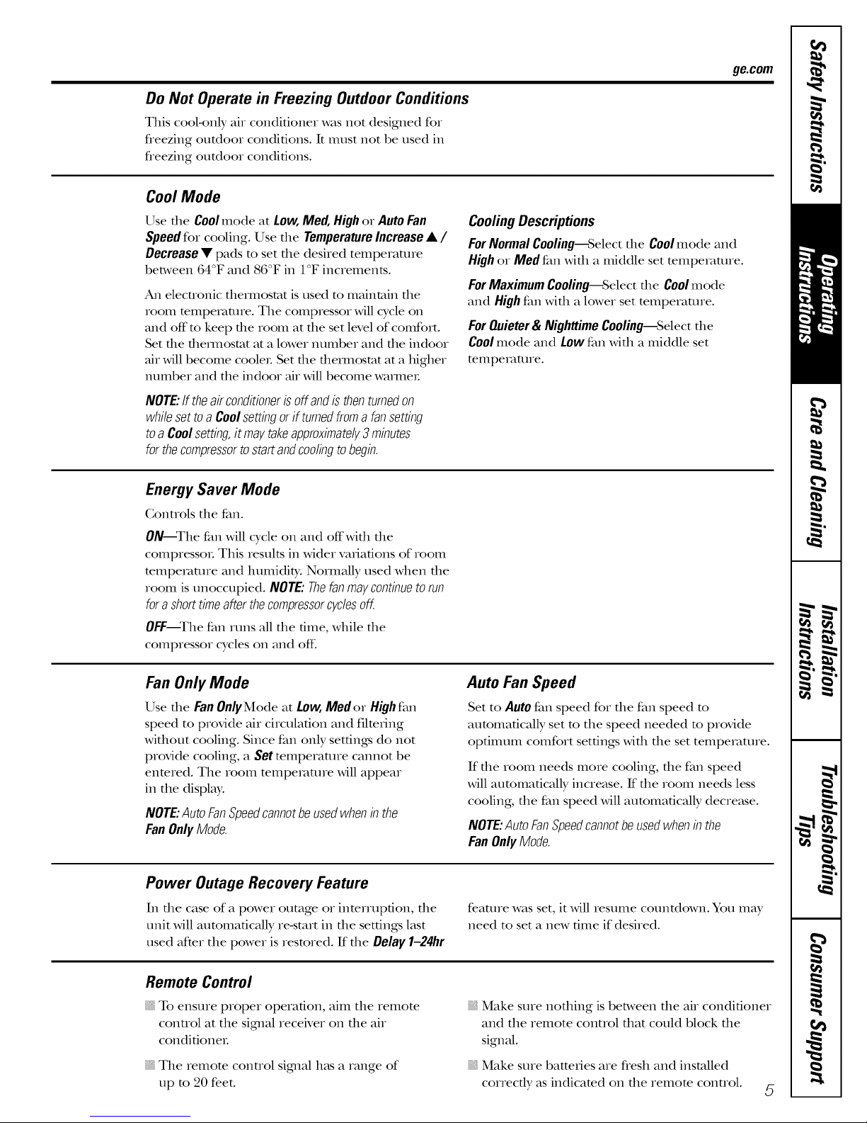
Aboutthecontrolsonthe air conditionermmodels with touchpads.
Lights next to the touch pads on the air conditioner control panel indicate the selected settings.
Thedisplayalwaysshowsthe room is in the temperatureor
temperatureexceptwhensetting the delaytimeSetmode.
SettemperatureoA th2 Delay timer. _I.1___ _
Lightindicatesthe unit
-.,o, oooo,y
: :Ec::;gys.... '- i4tyiilid2e?ti:Sst2
Lightindicates
Circulaireison.
Air Conditioner Controls
Controls
The air conditioner conuols are locmed behind die
control panel dooL Press to open and close die doo_:
NOTE:The remora conuol will work with the conuol
panel door open or closed.
O ower Pad
Turns air conditioner on and off: When
turned on, the display will show the room
temperature.
0 Display
Shows the room temperature or time
remaining on the Del W fimeL Shows the Set
mmperamre while setting the temperature in
Coolor Energy Saver modes. The Set light will
mrn on while setting.
NOTE:The display will change to show the
room temperature after settings have been
made. To recall the Setmmpexamre, press the
remp Increase • or Decrease • pads.
O emp Increase •/Decrease • Pads
Use to set temperature when in Coolor Energy
Savermode. The Setlight will turn on while
setting.
O Delay fimerlncrease • (+)/Decrease • (-)
Pads
Each touch of the Increase •/Decrease •
pads on the unit or the Increase +/Decrease -
pads on the remote control will set the delay
time when using the Delay 1-24hr diner (@).
The Setlight will mrn on while setting.
i an Speed Pads
Use to set the fan speed to LOW,Med, High
or Auto on the unit. NOTE: On the remote
control, use the fan speed Increase +/
Decrease -pads to set the fan speeds to LOW,
Med or High. Use the Auto pad to turn Auto
4
fail Oil.
0 Delay1-24hr
Delaytimer
Decrease
O Modeselect
O Fanspeed
Decrease
O Temperature
setlncrease
andDecrease
Delaytimer increase
Circulaire
Auto Fanon/off
Fanspeed Increase
Unit power on/off
Remote Control
O ode Pad
Use to set the air conditioner to Cool,Energy
Saveror FanOnlymode.
Delay Pads
0
Delay ON--When the air conditioner is off. it
can be set to automaticaUy come on in 1 to 24
hours at its pre_'ious mode and fan settings.
Delay OFF_\¥hen the air conditioner is on,
it can be set to automatically mrn offin 1 to
24 hours.
Howtoset:
Press file Delay 1-24hr pad on the unit or
die O pad on file remora conuol. Each touch
of the Increase •/Decrease • pads on the
unit or the Increase +/Decrease -pads on
the remora conuol will set the timer in
1-hour intervals. The Setlight will mrn on
while setting.
To review file remaining time on die Delay
1-24hr time_; press the Delay 1-24hr pad on the
unit or the @ pad on the remote control. Use
the Increase •/Decrease • pads on the unit
or the Increase +/Decrease -pads on the
remote control to set a new time if desired.
Tocancel the timer, press d_e Delay 1--24hr pad
until file light on the Delay 1-24hrpad goes off:
CIRCULAIREPad
0
Turn on to provide continuous side-to-side
air circulation.
For fixed side-to-side air direction, turn on
until the desired air direction is obtained,
then turn it off:
Page 5
Do Not Operate in Freezing Outdoor Conditions
This cool-only air conditioner was not designed for
fleezing outdoor conditions. It must not be used in
freezing outdoor conditions.
CoolMode
ge.com
Use the Coolmode at Low,Med,Highor AutoFan
Speedfor cooling. Use the TemperatureIncrease• /
Decrease• pads to set the desired temperature
between 64°F and 86°F in 1°F increments.
An electronic fllemlostat is used to mMntain file
room temperature. The compressor will cycle on
and off to keep file room at file set level of comfort.
Set file fllemlostat at a lower number and file indoor
air will become cooleL Set file thealilostat tit a higher
number and the indoor air will become wamleL
NOTE:ff theairconditionerisoffandisthenturnedon
whilesettoa Coolsettingorif turnedfromafansetting
toa Coolsetting,it maytakeapproximately3minutes
forthecompressortostartandcoolingtobegin.
Energy Saver Mode
Gontrols the fan.
ON--The fan will cycle on and offMfll file
compressoL This results in Mder variations of room
temperature and humidity. NonnMly used when file
room is unoccupied. NOTE: Thefan maycontinue to run
fora short time after the compressorcyclesoff.
OFF--The fan runs all file time, while file
compressor cycles on and off:
CoolingDescriptions
ForNormalCooling--Selectthe Coolmode and
Highor IViedfan with a middle set temperature.
For Maximum Cooling--Select the Cool mode
and High fan with a lower set temperature.
For Quieter & Nighttime Cooling--Select the
Coolmode and Low fan with a middle set
temperature.
Fan Only Mode
Use the Fan OnlyMode at Low, Medor Highfan
speed to provide air circulation and filtering
without cooling. Since fan only settings do not
provide cooling, a Set mmperamre camlot be
enmred. The room mmpemmre will appear
in the displ W.
NOTE:AutoFanSpeedcannotbeusedwheninthe
FanOnlyMode.
Power Outage Recovery Feature
In the case of a power outage or interruption, the
unit will automatically re-start in the settings last
used after the power is restored. If the Delay1-24hr
Remote Control
To ensure proper operation, aim the remote
control at the signal receiver on the air
condifioneL
The remote control sigmal h_tsa range of
lap to 20 feet.
Auto Fan Speed
Set to Auto fan speed for the fan speed to
automatically set to the speed needed to provide
optimum comfort settings with the set tempemtme.
If the room needs more cooling, the fan speed
will automatically increase. If the room needs less
cooling, the fan speed will automatically decre_tse.
NOTE:AutoFanSpeedcannotbeusedwheninthe
FanOnlyMode.
feature was set, it will resume countdown. You may
need to set a new time if desired.
, Make sure noflfing is between file air conditioner
and the remote control fllat could block file
signal.
, Make sure batteries are flesh and installed
correctly as indicated on file remote conuol.
5
Page 6
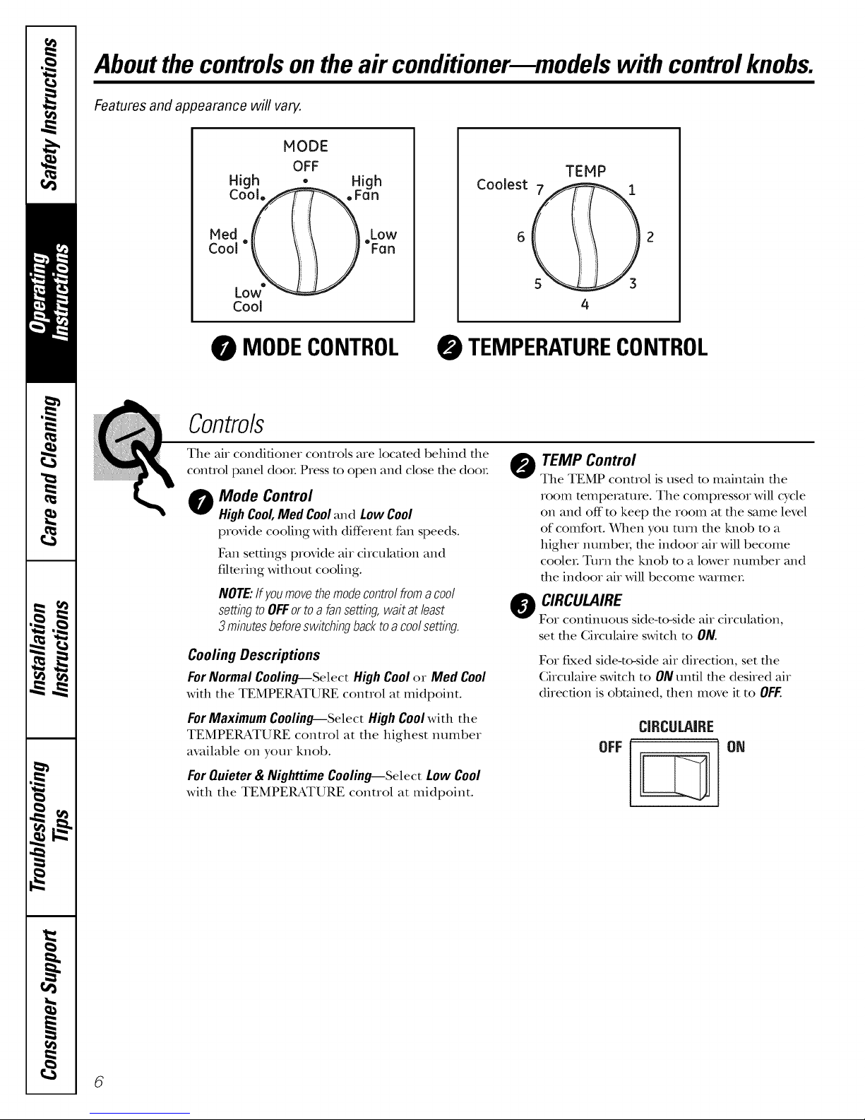
Aboutthecontrolsonthe air conditionermmodelswith controlknobs.
Features and appearance will vary.
NODE
OFF
High _ High
COOJ, y ,,i _,Farl
Coolest 7 1
TENP
\
6
Low"
CoN
MODECONTROL
TEMPERATURECONTROL
Contro/s
The air conditioner controls are located behind the ,_
Mode Control
O
High Cool,Med Cool and Low Cool
provide cooling with (liff_rent fan speeds.
Fan settings provide air circulation and
filmring without cooling.
NOTE:If youmovethemodecontrolfroma cool
settingtoOFFortoa fansetting,waitat least
3 minutesbeforeswitchingbacktoa coolsetting.
Cooling Descriptions
ForNormal Cooling--Select HighCoolor Med Cool
with the TEMPERATURE control at midpoint.
For Maximum Cooling--Select High Cool with the
TEMPERATURE control at the highest number
available on your knob.
ForQuieter& NighttimeCooling--Select Low Cool
with the TEMPERATURE control at midpoint.
5 3
TEMP Control
r.#control panel doo_. Press to open and close the dooL
The TEMP control is used to maintain the
room temperature. The compressor will cycle
on and off m keep the room at the same level
of comfort. When you ann the ]_lob to a
higher numbex; the indoor air will become
cooler. Turn the knob m a lower number and
the indoor air will become warme_.
O CIRCULAIRE
For continuous side-to-side air circulation,
set the Circulaire switch to ON.
For fixed side-to-side air direction, set the
Circulaire switch to ON until the desired air
direction is obtained, then move it to OFF.
OFF
ON
6
Page 7
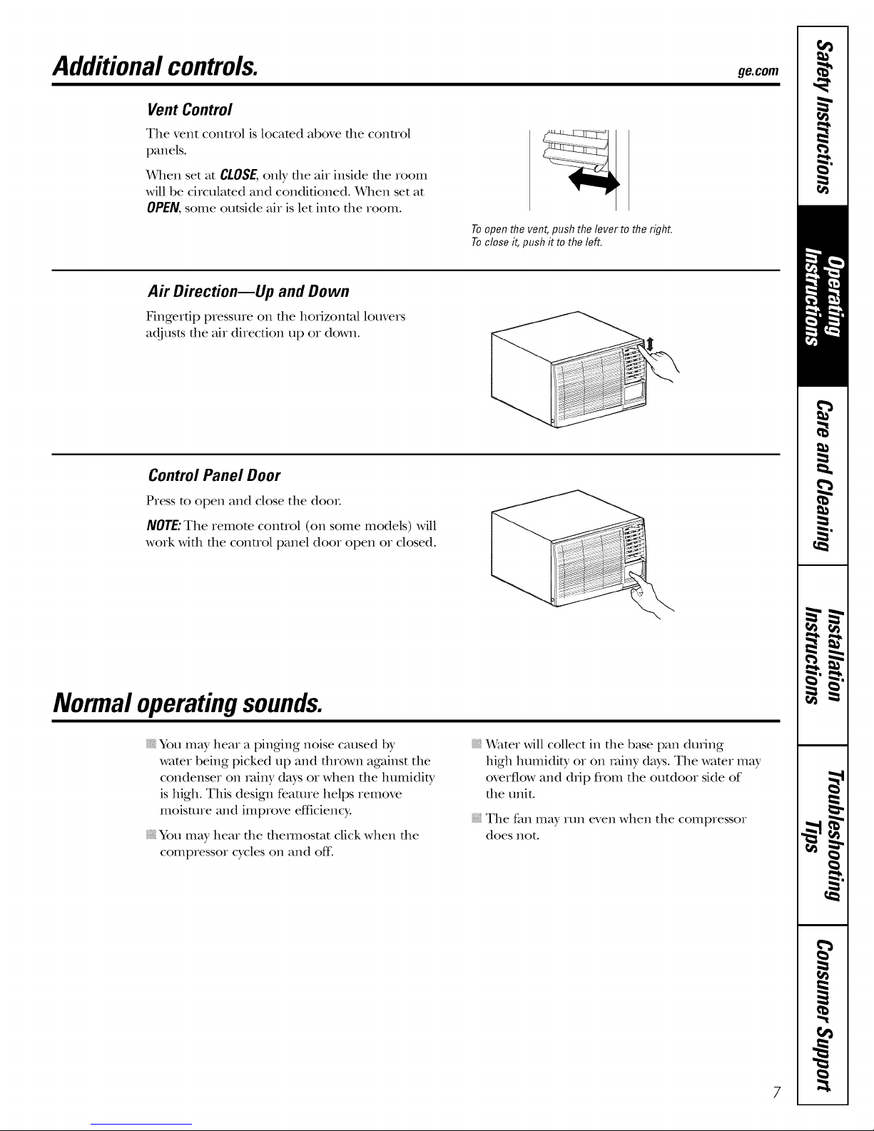
Additionalcontrols, geoom
Vent Control
The vent control is located above tile control
panels.
When set at CLOSE,only tile air inside tile room
will be circulated and conditioned. When set at
OPEN, some outside air is let into tt_e room.
Toopen the vent, push the lever to the right.
Toclose it, push it to the left.
A# D#ection--Up and Down
Fingertip pressure on the horizontal louvers
adjusts the air direction up or down.
Control Panel Door
Press to open and close the dooL
NOTE: The remote control (on some models) will
work with tile control panel door open or closed.
Normal operatingsounds.
You may hear a pinging noise caused by
wamr being picked up and thrown against the
condenser on _vfinydays or when the humidity
is high. This design feature helps remove
moisture and improve efficienc>
You may hear file flleimostat click when file
compressor cycles on and off:
Water will collect in die b_tse pan during
high humidity or on _finy days. The water may
overflow and d;ip flom the outdoor side of
the unit.
The fan may run even when the compressor
does not.
Page 8
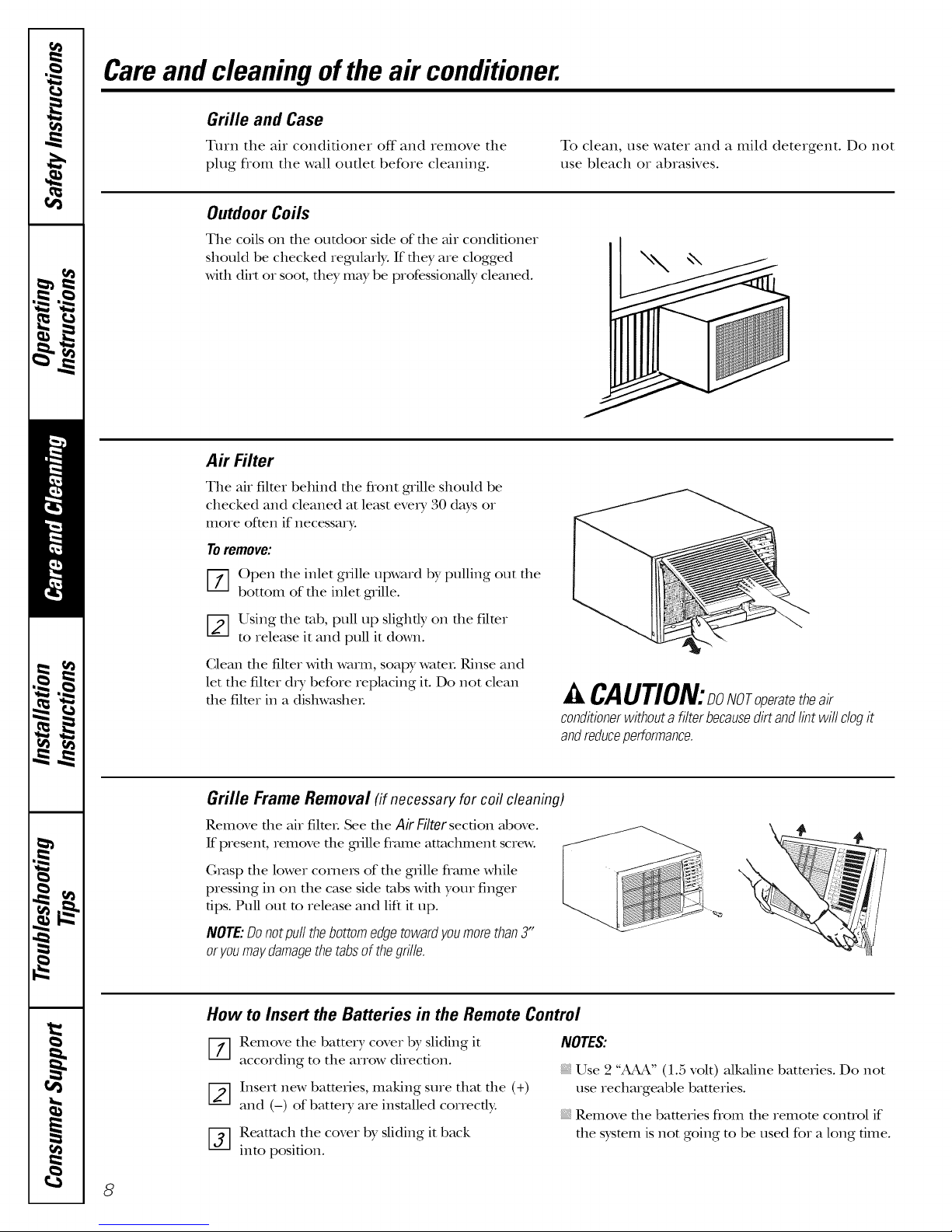
Careand cleaning ofthe air conditioner.
Grille and Case
Turn the air conditioner off and remove the To clean, use water and a mild detergent. Do not
plug flom the wall outlet before cleaning, use bleach or abrasives.
OutdoorCoils
The coils on the outdoor side of the air conditioner
should be checked regularly: If flley are clogged
Mr1 dirt or soot, flley may be professionMly cleaned.
Air Filter
The air filter behind the front grille should be
checked and cleaned at least eve_T 30 days or
more often if necessary.
Toremove:
[-_ Open the inlet grille upward by pulling out the
bottom of the inlet grille.
[-2--]Using the rob, pull up slightly on the filter
to release it and pull it down.
Clean the filter with winm, soapy wamL Rinse and
let the filmr d_T before replacing it. Do not clean
the filter in a dishwasheL
conditionerwithoutafilterbecausedirt andlintwill clogit
andreduceperformance.
Grille Frame Removal (if necessary for coil cleaning)
Remove the air filteL See the Air Filtersection above.
If present, remove the gnille fl_mle attachment screw.
Grasp the lower comets of the gIille flmne while
pressing in on the case side robs with your finger
tips. Pull out to release and lift it up.
NOTE:Donotpullthebottomedgetowardyoumorethan3"
oryoumaydamagethetabsofthegrille.
How to Insert the Batteries in the Remote Control
k, CAUTION:DoNoToperatetheair
[-_ Remove the battery cover by sliding it
according to the arrow direction.
Insert new batteries, making sure that the (+)
and (-) of battery are installed conecd):
[-_ Reatmch the cover by sliding it back
into position.
8
NOTES:
Use 2 "_" (1.5 volt) alkaline bmtefies. Do not
use rechmgeable batteries.
Remove the batteries flom the remora control if
the sysmm is not going m be used for a long time.
Page 9
ilnsta,,at,onnsttuct,onsIAirC°ndit'°nerl
I_ Questions? Call 800.GE.CARES (800.432.2737) or Visit our Website at: ge.com I
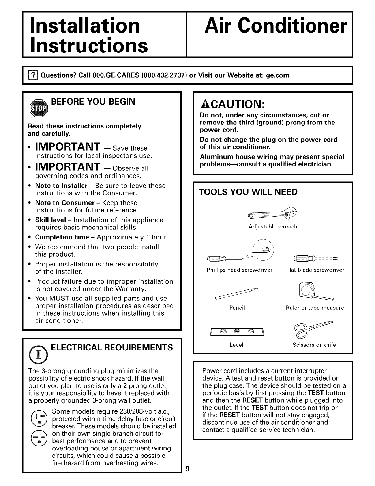
BEFORE YOU BEGIN
Read these instructions completely
and carefully.
IMPORTANT - Savethese
instructions for local inspector's use.
• IMPORTANT - Observeall
governing codes and ordinances.
• Note to Installer- Be sure to leave these
instructions with the Consumer.
• Note to Consumer- Keep these
instructions for future reference.
• Skill level - Installation of this appliance
requires basic mechanical skills.
• Completion time- Approximately 1 hour
• We recommend that two people install
this product.
• Proper installation is the responsibility
of the installer.
Product failure due to improper installation
is not covered under the Warranty.
You MUST use all supplied parts and use
proper installation procedures as described
in these instructions when installing this
air conditioner.
- CAUTION:
Do not, under any circumstances, cut or
remove the third (ground) prong from the
power cord.
Do not change the plug on the power cord
of this air conditioner.
Aluminum house wiring may present special
problemsmconsult a qualified electrician.
TOOLS YOU WILL NEED
Adjustable wrench
Phillips head screwdriver
Pencil
Flat-blade screwdriver
Ruler or tape measure
_ ELECTRICAL REQUIREMENTS
The 3-prong grounding plug minimizes the
possibility of electric shock hazard. If the wall
outlet you plan to use is only a 2-prong outlet,
it is your responsibility to have it replaced with
a properly grounded 3-prong wall outlet.
Some models require 230/208-volt a.c.,
protected with a time delay fuse or circuit
breaker. These models should be installed
on their own single branch circuit for
best performance and to prevent
overloading house or apartment wiring
circuits, which could cause a possible
fire hazard from overheating wires.
Level
Power cord includes a current interrupter
device. A test and reset button is provided on
the plug case. The device should be tested on a
periodic basis by first pressing the TEST button
and then the RESET button while plugged into
the outlet. If the TEST button does not trip or
if the RESET button will not stay engaged,
discontinue use of the air conditioner and
contact a qualified service technician.
9
Scissors or knife
Page 10
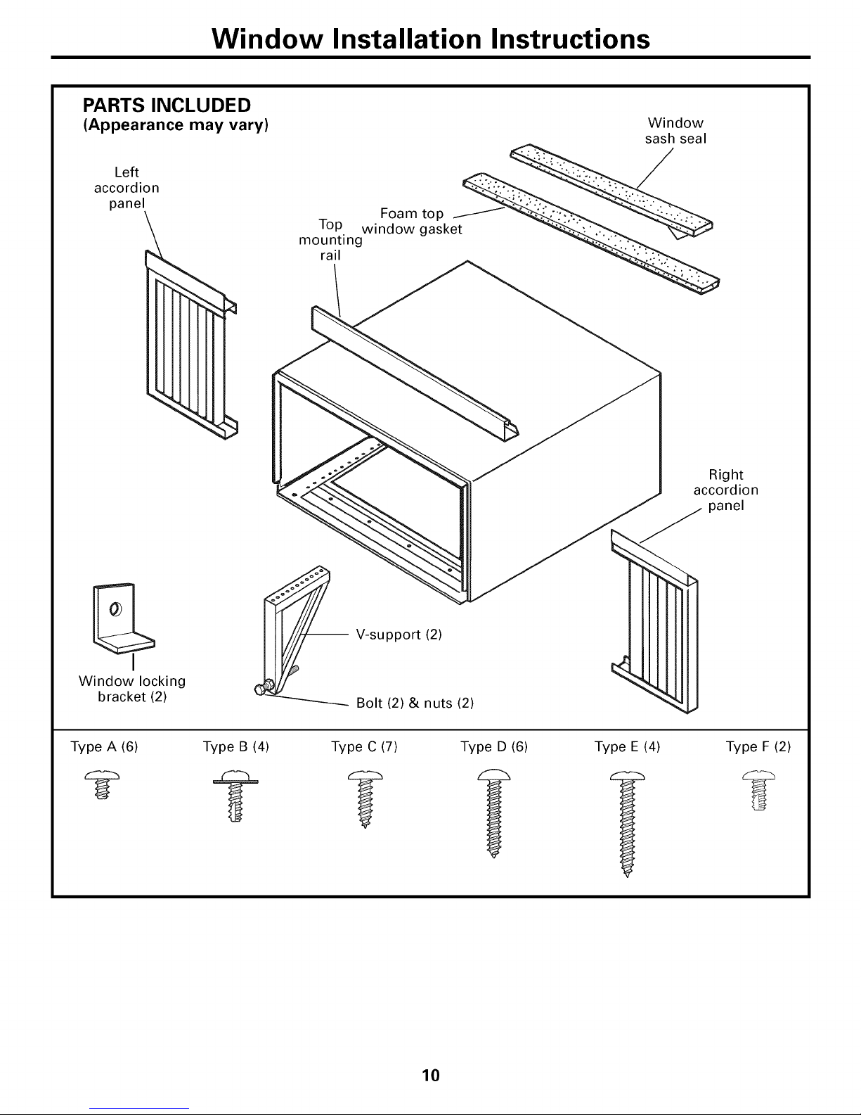
Window Installation Instructions
PARTS INCLUDED
(Appearance may vary)
Left
accordion
panel
Window
sash seal
mounting
rail
Right
accordion
panel
-- V-support (2)
Window locking
bracket (2)
Type A (6) Type B (4) Type C (7) Type D (6) Type E (4) Type F (2)
Bolt (2) & nuts (2)
10
Page 11
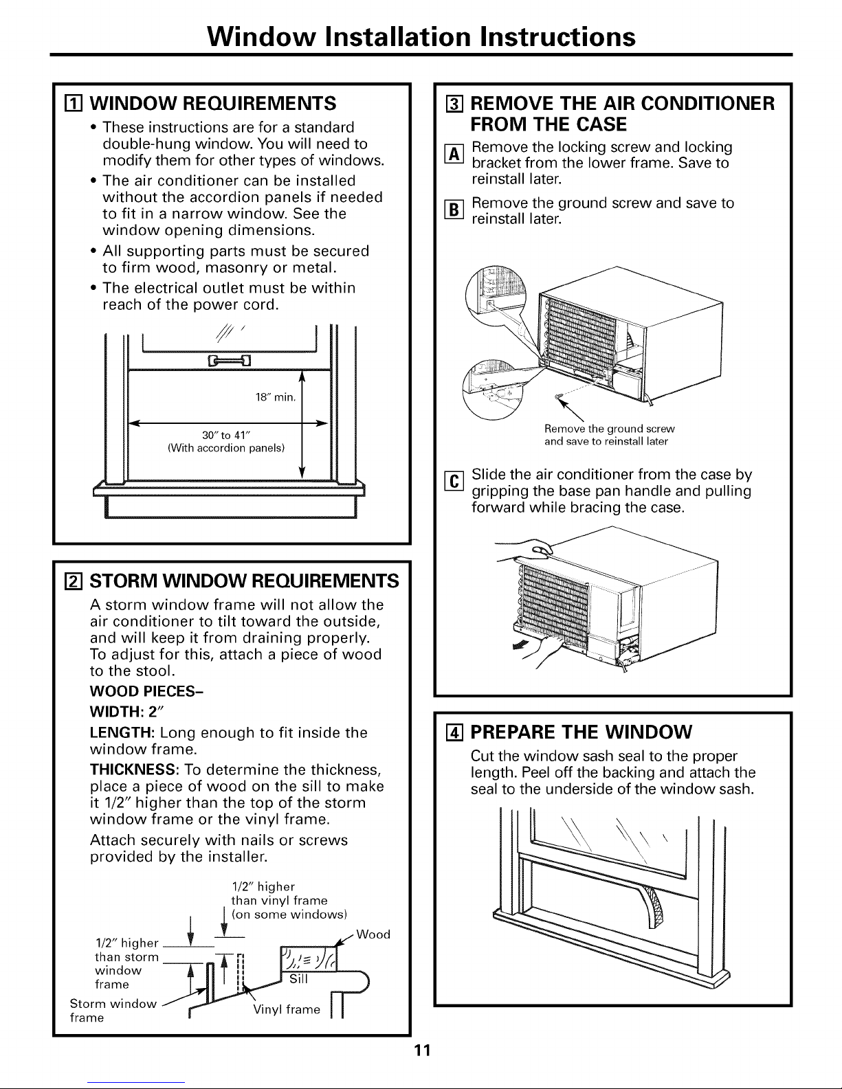
Window Installation Instructions
WI WINDOW REQUIREMENTS
• These instructions are for a standard
double-hung window. You will need to
modify them for other types of windows.
• The air conditioner can be installed
without the accordion panels if needed
to fit in a narrow window. See the
window opening dimensions.
• All supporting parts must be secured
to firm wood, masonry or metal.
• The electrical outlet must be within
reach of the power cord.
[ //"
18" min.
30" to 41"
(With accordion panels)
[] REMOVE THE AIR CONDITIONER
FROM THE CASE
Remove the locking screw and locking
bracket from the lower frame. Save to
reinstall later.
Remove the ground screw and save to
reinstall later.
Remove the ground screw
and save to reinstall later
3h
J
[] Slide the air conditioner from the case by
gripping the base pan handle and pulling
forward while bracing the case.
[_] STORM WINDOW REQUIREMENTS
A storm window frame will not allow the
air conditioner to tilt toward the outside,
and will keep it from draining properly.
To adjust for this, attach a piece of wood
to the stool.
WOOD PIECES-
WIDTH: 2"
LENGTH: Long enough to fit inside the
window frame.
THICKNESS: To determine the thickness,
place a piece of wood on the sill to make
it 1/2" higher than the top of the storm
window frame or the vinyl frame.
Attach securely with nails or screws
provided by the installer.
1/2" higher
than vinyl frame
L (on some windows)
/
w
than storm
1/2" higher--_T- rl_ _Wood
window
frame _Sill [._
Storm window
frame - r'_ Vinyl frame I I
141PREPARE THE WINDOW
Cut the window sash seal to the proper
length. Peel off the backing and attach the
seal to the underside of the window sash.
11
Page 12
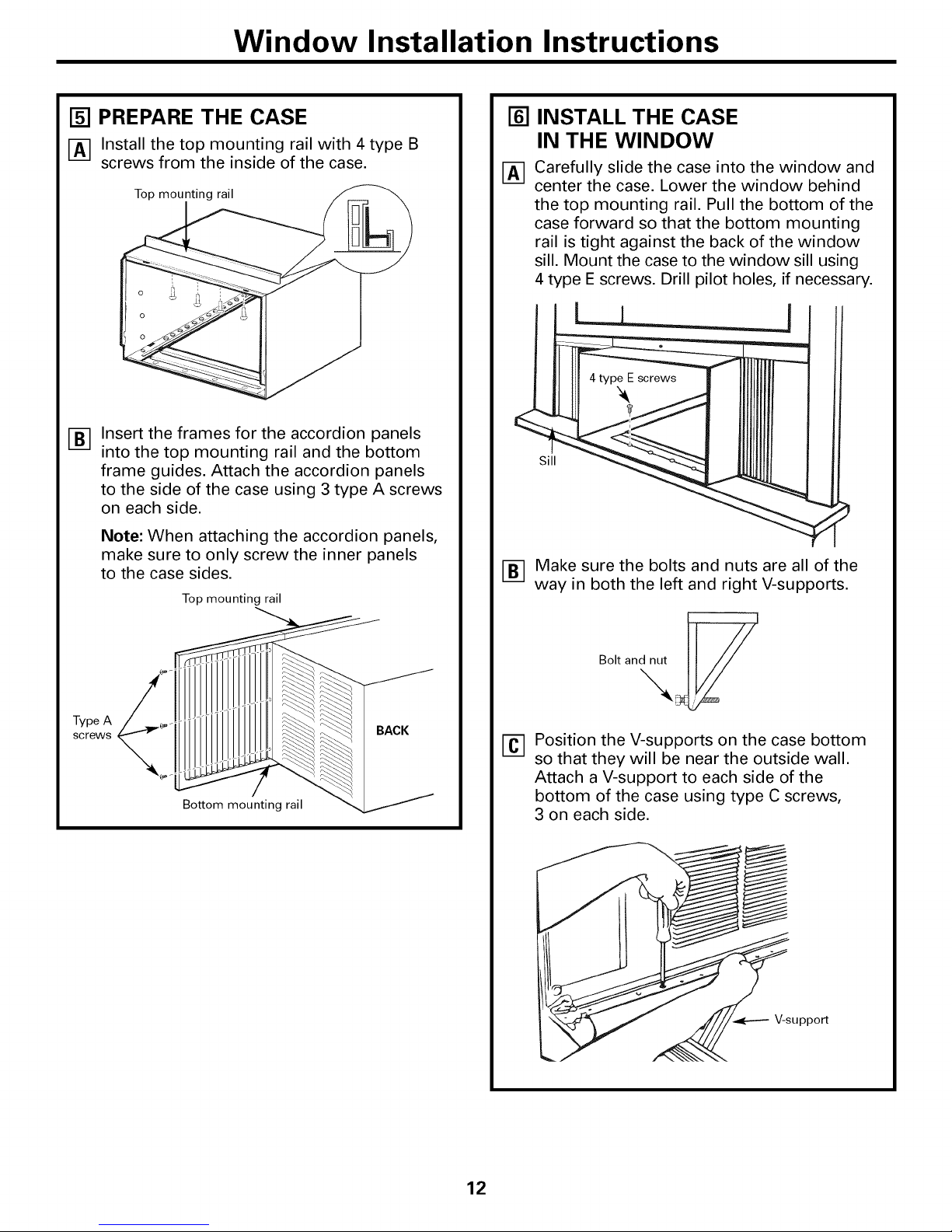
Window Installation Instructions
[] PREPARE THE CASE
I-A-] Install the top mounting rail with 4 type B
screws from the inside of the case.
Insert the frames for the accordion panels
®
into the top mounting rail and the bottom
frame guides. Attach the accordion panels
to the side of the case using 3 type A screws
on each side.
Note: When attaching the accordion panels,
make sure to only screw the inner panels
to the case sides.
Top mounting rail
INSTALL THE CASE
IN THE WINDOW
Carefully slide the case into the window and
center the case. Lower the window behind
the top mounting rail. Pull the bottom of the
case forward so that the bottom mounting
rail is tight against the back of the window
sill. Mount the case to the window sill using
4 type E screws. Drill pilot holes, if necessary.
__J
Sill
® Make sure the bolts and nuts are all of the
way in both the left and right V-supports.
Type A
screws
Bottom mounting rail
BACK
Position the V-supports on the case bottom
[]
so that they will be near the outside wall.
Attach a V-support to each side of the
bottom of the case using type C screws,
3 on each side.
V-support
12
Page 13

Window Installation Instructions
[] INSTALL THE CASE
IN THE WINDOW (cont.)
[_ Use a wood block (obtained locally) between
the leveling bolts and the wall if the wall is
weak or if the weight of the air conditioner
falls between the studs in the wall.
[_ Adjust the leveling bolts and nuts against the
outside wall so that the case has a slight tilt
to the outside. -Iqghten nuts with an adjustable
wrench. Use a level; no more than a 1/2 bubble
will be the correct case slant to the outside.
171INSTALL SUPPORT BRACKETS
AND THE FOAM TOP WINDOW
GASKET
[_] Drill pilot holes and attach the support
brackets with two type D screws, one on
each side.
l I
Cut the foam top window gasket to the
__J
window width.
Stuff the foam between the glass and the
window to prevent air and insects from
getting into the room.
[_ Extend the left and right accordion panels
to the vertical window sashes. Drill pilot
holes and attach the top and bottom corners
with 4 type D screws.
Top mounting rail
Type D
screw
Type D
screw
Type D
screw
Type D
screw
13
Page 14

Window Installation Instructions
[] INSTALL THE AIR CONDITIONER
IN THE CASE
_-] Make sure the ground
wire is off to the side _
and slide the air
conditioner into the
case. Do not push
on the controls or the
finned coils. Make
sure the air
conditioner is
firmly seated.
[_ Reinstall the locking bracket and screw
removed earlier.
Reconnect the ground wire to the air
FCq
conditioner using the screw removed earlier.
IMPORTANT: The ground wire must be
reinstalled to ensure a proper ground.
INSTALL THE AIR CONDITIONER
IN THE CASE (cont.)
[_ Pull the coiled power cord from its shipped
position in the air discharge area. Attach
the front grille frame to the case by inserting
the tabs on the grille frame into the slots
on the front top of the case.
Guide the lever carefully
through the grille frame
as you push it in.
Press the grille frame in around the power
Fm
cord on the right side. Secure the grille with
a type F (painted) screw on each side and a
type C screw in the front.
Type F
screw
[_ Remove the front grille from its box and
remove the shipping tape.
[_ Grasp the inlet grille at the bottom corners
and pull it forward. Unhook it from its top
hinges and set it aside.
[_ Using the tab, pull up slightly on the filter
to release it and pull it down and out.
,/
Type F
screw
Type C screw
_-I Reinstall the filter.
[] Reinstall the inlet grille. Connect power.
Caulk or weather-strip any gaps or openings
to the outside to seal the installation.
14
Page 15

Through-the-Wall Installation InstructionsmOptional
The case may be installed through-the-wall
in both existing and new construction.
Read completely, then follow step-by-step.
NOTE: Except for the V-support
assemblies (included), obtain all materials
locally for mounting the air conditioner
through-the-wall.
ITI IMPORTANT
Through-the-wall installation is not
appropriate if any of the side or top louvers
in the case will be obstructed by the wall.
All side and top louvers in the case must
project on the outdoor side of the wall.
The room side of the case must project
into the room far enough to maximize the
balance of the unit.
The case must be installed level from side-
to-side and with a slight tilt from front to
rear. Use a level; no more than a 1/2 bubble
will be the correct case slant to the outside.
Lintel angle is required to support bricks or
blocks above opening.
Flashing is required and should extend the
length of the opening to ensure no inside
cavity leakage occurs.
Remove the air conditioner from the case.
L/_.tJ
For specific instruction, refer to the Window
Installation Instructions.
[_ Make certain that a wall receptacle is
available close to the hole location or make
arrangements to install a receptacle.
ITI IMPORTANT (cont.)
[_ Secure with 14 wood screws anchored at
least an inch into the wall support structure.
NOTE: Drill pilot holes, if necessary, for
proper installation. If the frame is oversized,
use shims to prevent case distortion.
Install the V-supports. See the INSTALL
THE CASE IN THE WINDOW section in the
Window Installation Instructions.
121FINISH THE WALL OPENING
[] Caulk all four sides on the outdoor side of
the case to prevent moisture from getting
through to the interior wall. Use of flashing
(drip rail) will further prevent water from
dripping inside the wall and down the
outside of the building.
Plaster line
Lintel angle
Caulking _ (if desired)
OUTSIDE l_ INSIDE
Air louvers P
(top and //_'Jlv _
•. / ._Y_" -- Bottom rail
sides must _'- I _ /
project on the I _ /
outdoor side I _ /
°fthewal') I _
Wood filler and X_._/'/_/_ ,_,./I J_
caulking (above/_ A I "IdOl I
and below the " \Y, I1 Ilf/_/ll/lll
flashing) _/_ l ] [ _I l "
V-supports / _
Flashing / bottom rail
/ Case Bottom
Trim molding
[] Place the case in the wall opening and place
wood support strips between the case
bottom and the flashing on both sides of the
bottom rail. They should be the same height
as the bottom rail and the same length as
the wall opening.
15
(Drip rail) _
Flashing
(Drip rail)
Place the air conditioner into the case.
i-'1
For specific instruction, refer to the Window
Wood support strips
Installation Instructions.
Page 16

TroubleshootingTips.
Troubleshooting -tips.Save time and money! Review the chart below
first and you may not need to call for service.
Possible Causes What ToDo
Airconditioner
doesnotstart
Airconditionerdoes not Airflow is restricted. • Make sure there me no curtains, blinds or fiunitme
cool as it should blocking the flont of the air condifioneL
The air conditioner
is unplugged.
The fuse is blown/circuit
breaker is tripped.
Power failure.
• Make sure file air conditioner plug is pushed completely
into file outlet.
• Check the house fllse/circuit breaker box and replace
the fuse or reset the breakeL
• The unit will automatically re-start in the settings last
used after the power is restored.
• There is a promctive time del W (approximately 3 minutes)
m prevent uipping of the compressor overload. For this
reason, the unit m W not start normal cooling for
3 minums after it is turned back on.
The current interrupter • Press the RESETbutton located on the power cord plug.
device is tripped. • If the RESErbuttonwill not stay engaged, discontinue
use of the air conditioner and contact a qualified service
teclmician.
The temp control may not • On models with touch pads: In the Cool mode, press the
be set correctly. Decrease • pad.
• On models wifll control knobs, mrn file temperature
knob to a higher numbeL
The air filter is dirty. • Glean the filter at least every 30 days. See the
Care and Cleaning section.
The room may have been hot. • When file air conditioner is fi,st turned on, you need to
Cold air is escaping.
allow time for file room to cool down.
• Check fox open flxxnace floor xegismxsand cold air xemms.
• Set the air condifionex"s vent to the closed position.
• See "Air conditionerfreezingup" below.
• On models with control knobs, setthe mode control at
HighFanor HighCoolwiththe TempatI or 2
• On models with touch pads, set the controls at HighFan
Air conditioner
freezingup
Cooling coils have iced up.
Ice blocks the air flow and
stops the air conditioner
from cooling the room.
or HighCooland set the tl_em_ostatto a higher
tempemtme.
Theremote control The batteries are inserted * Gheck the position of file batteries. They should be
is not working incorrectly, inserted in the opposite (+) and (-) direction.
The batteries may be dead. *Replace the batteries.
Water drips outside Excessively hot and • This is normal.
humid weather.
Waterdrips indoors The air conditioner is not • Fox proper water disposal, make sure file air conditioner
tilted to the outside, slants slightly flom the case flont to the real
Water collects in
base pan
Moisture is removed from
indoor air and drains into
rear of a cabinet where a fan
blows it against the outdoor
condenser coil.
• This is nomlal for a short period in areas widl little
humidity; normal for a longer period in vexy humid areas.
Delay1-24hrfeaturenot
workingproperly
A power outage or interruption
occurred.
16
* The unit will automatically re-start in the settings last used
after the power is restored. If the Delay 1-24hrfeature was
set, it will resume countdown. You m W need m set a new
time if desired.
Page 17

GE Service Protection Plus TM
GE, a name recognized worldwide for quality and dependability, ()tiers you
Service Protection Plus"*--comprehensive protection on all your appliances--
No Matter What Brand!
Benefits Include:
• Backed by GE
• All brands covered
• Unlimited service calls
• All parts and labor costs included
• No out-of-pocket expenses
• No hidden deductibles
• One 800 number to call
You will be completel), satisfied with ou_ seevice p_otection o_ you ma), _equest you_ money back
on the _emaining value of you_ cont,act. No questions asked. It's that simple.
P_otect you_ _eflige_ato_; dishw_she_; washe_ and d_ye_; _ange, TV, VCR and much moie--any brand!
Plus the_e's no ext_a chaige fo_ emeigency seevice and low monthly financing is ttwailable. Even icemake_
cove__tge and food spoilage piotecfion is off_ed. You can iest easy, knowing that all you_ valuable
household p_oducts a_e p_otected against expensive _epai_s.
Place youx con_deilce in (_E and call us in the U.S. toll-f_ee at 800.626.2224
fo_ mo_e infomlation.
_:All brands (:ox'ered, tlI) lo 20 v( _a_'sold, in lh(_ (:onlin(_nl_al U.S.
We71CoverAnyAppfiance.
Anywhere. Anytime.*
.................. ....
Pleaseplacein envelopeandmail to:
General Electric Company
Warranty Registration Department
P.O. Box 32150
Louisville, KY 40232-2150
17
Page 18

Consumer Product Ownership Registration
Dear Customer:
Thank you for purchasing our product and thank you for placing your confidence in us.
We are proud to have you as a customer!
Follow these three steps to protect your new appliance investment:
Complete and mail
your Consumer
Product Ownership
Registration today.
Have the peace of
mind of knowing we
can contact }Oil iI]
the unlikely event of a
satet} modification.
Afer mailing the
registration bel(m,
store this document
in a sate' place. It
contains intormation
}ou will need should
}ou require service.
Our service nmnber is
800.(;E.CARES
(800.432.2737).
Model Number Serial Number
Important: If you did not get a registration card with your
product, detach and return the form below to
ensure that your product is registered, or register
online at ge.com.
Consumer Product Ownership Registration
Read }our ()_aler's
Mamml careflHly.
It will help }ou
operate }otlr ilew
appliance properl}
,_.._ (;ut here
Model Number Serial Number
M_; Ms. Mrs. Miss
First I_st
Namel I I I I I I I I I I Name I I I I
Street [
Address I I I I I I I I I I I I I I I I I I I I I I I
I I
ap_.#l , I I I I I , I E-maUA_ress*
Zip
Date Placed
'"_1 , I Da,I , I ,_arl. I Pho.e_.mberl I, I-I,, Iq
Month
* Please provide )our e-mail address to receive, via e-mail, discotmts, special offers and other
GE Consumer & Industrial
Appliances
General Electric Company
Louisville, KV40225
ge.com
18
important commtmications fl'om GE Appliances (GEA).
Check here if }ou do not want to receive commtmications fl'om GEA's carefull} selected
partners.
FAILURE TO COMPLETE AND RETURN THIS CARD DOES NOT DIMINISH YOUR
_,t_kRRANTY RIGHTS.
For information about GEA's privacy and data usage policy, go to ge.com and click on "Privacy
Policy" or call 800.626.2224.
Page 19

GEAir ConditionerWarranty.
Aft warranty service provided by our Factory Service Centers,
or an authorized Customer Care®technician. Toschedule service,
on-line, visit us at ge.com, or carl 800.GE.CARES(800.432.2737).
Have serial number and model number available when cafling
for service.
GE Will Replace:
OneYear
Fromthe!dateofthei!
originalpurchase
Service trips to your home to teach you how to
use the product.
Improper installation, delivery or maintenance. If you
have an installation problem, or if the air conditioner
is of improper cooling capacity for the intended use,
contact your dealer or installer. You are responsible
for providing adequate electrical connecting facilities.
Failure of the product resulting from modifications to
the product or due to unreasonable use including failure
to provide reasonable and necessary maintenance.
In commercial locations, labor necessary to move the
unit to a location where it is accessible for service
by an individual technician.
Anypartof file air conditioner which fails due to a defect in materials or workmanship.
During this limited one-year warranty, GE will also provide, free of charge, all labor and relamd
se_Mce to replace the defective part.
Staple your receipt here.
Proof of the original purchase
date is needed to obtain service
under the warranty.
Replacement of house fuses or resetting of circuit
breakers.
Failure due to corrosion on models not corrosion-
protected.
Damage to the product caused by improper power supply
voltage, accident, fire, floods or acts of God.
Incidental or consequential damage caused by possible
defects with this air conditioner.
Damage caused after delivery.
EXCLUSION OFIMPLIED WARRANTIES--Your sole and exclusive remedy isproduct repair as provided in this
Limited Warranty. Any implied warranties, including the implied warranties of merchantability or fitness for a
particular purpose, are limited to one year or the shortest period allowed by law.
This warranty is extended to the original purchaser and any succeeding owner for products purchased for home
use within the USA. In Alaska, the warranty excludes the cost of shipping or service calls to your home.
Some states do not allow the exclusion or limitation of incidental or consequential damages. This warranty gives
you specific legal rights, and you may also have other rights which vary from state to state. To know what your
legal rights are, consult your local or state consumer affairs office or your state's Attorney General
Warrantor: General Electric Company.Louisville, KY 40225
19
Page 20

ConsumerSupport.
GEAppliancesWebsite
Have a question or need assistance with your appliance? Try the GE Appliances Website any day of the year!
Fox greater convenience and faster service, you can now download Owner's Manuals, order parts or even
schedule sex_qceon-line.
ScheduleService
Expert GE repair service is only one step away from your doox. Get on4ine and schedule your service at
your convenience 24 horns any day of the year[ Or c_fll800.GE.CARES 800.432.2737) during nomml
business hours.
RealLifeDesignStudio
GE supports the Universal Design concept--products, services and envuonments that can be used by
people of aU ages, sizes and capabilities. We recogmize the need m design for a wide range of physical and
mental abilities and impaimlents. Fox derails of GE's Univexsal Design applications, including kitchen
design ideas for people with disabilities, check out our Website today. Fox the hearing impaired, please call
800.TDD.GEAC (800.833.4322).
ExtendedWarranties
ge.com
ge.com
ge.com
ge.com
Purchase a GE extended warranty and learn about special discounts that are available while your warranty
is still in effect. You can purchase it on-line anytime, or call 800.626.2224 during nomml business horns.
GE Consumer Home Sex_ices will still be there meteryour warranly expires.
PartsandAccessories
IndMduals qualified to service their own appliances can have parts or accessories sent directly to their
homes (VISA, MasterCard and Discover cards are accepted). Order on-line today, 24 horns every day
or by phone at 800.626.2002 during nomml business horns.
Instructionscontainedinthismanualcoverprocedurestobeperformedbyanyuser.Otherservicing generally
shouldbe referredto qualifiedservicepersonnelCautionmustbeexercised,sinceimproperservicingmaycause
unsafeoperation.
ContactUs
If you are not satisfied wit1 die service you receive flom GE, contact us on our Website wit1 all die derails
including your phone numbex; or wrim m: General Managex; Customer Relations
GE Appliances, Appliance Park
I,ouisville, KY40225
RegisterYourAppliance
ge.com
ge.com
ge.com
Register your new appliance on-line--at your convenience! Timely product registration will allow for
enhanced communication and prompt sexa_iceunder the temls of your warranly, should the need arise.
You may also mail in the pre-printed registration card included in the packing material.
20 Printed in China
Page 21

Ins*rucciones de seguridad ..... 2, 3
Ins_ucdones de operaci6n
Controles adicionales ............ 7
Modelos con botones de control...6
Modelos con teclas de toque .... 4, 5
Sonidos de operaci6n
normales ...................... 7
Cuidado y limpieza
Bobinas para exteriores .......... 8
Fihro de aire .................... 8
Rejilla y caja ................... 8
Instrucciones de instalaci6n
Instalaci6n a tray,s
de la pared--opcional ....... 15, 16
Instalaci6n en una ventana .... 9-14
ge.com
AEHI 8*
AEM18*
AEQ24
AEV24
AEW24
AE H25-'_
AEM25*
©
Solucionar problemas ...... 17, 18
Apoyo al consumidor
Apoyo al consumidor ........... 20
Garan6a ...................... 19
Producto etiquetado :_:ENERGYSTAR®
Como socio de ENERGYSTAR ®,
GE ha confirmado que este
producto cumple las direcuices
de ENERGYSTAR®relativas al
rendimiento energ_fico.
Escribalos mJmemsde modelo
y serie aqui:
©
# de Modelo
#de Serie
Puede encontrar estos nfimeros
en una efiqueta en el costado del
acondicionador de aire.
49-7587 11-07dfl
Page 22

INFORMACIONIMPORTANTEDESEGURIDAD.
LEATODASLASINSTRUCCIONESANTESDEUSAR.
iAD VERTENCIA!
Porsu seguridad,sedebeseguirla informaciSnenestemanualparaminimizarelriesgo deincendios,
descargasel6ctricaso lesionespersonales.
PRECAUCIONESDESEGURIDAD
Use este electrodom_stico solamente para
el prop6sito determinado se_n se describe
en el Manual del propietano.
iiiiiiiiiiii_iii
Este acondicionador de aire debe instalarse
correctamente de acuerdo con las
Instmcciones de instalaci6n antes de su uso.
iiiiiiiiiiii_iii
Nunca desenchufe su acondicionador de
aire tirando del cable el_ctfico. Siempre
agarre firmemente el enchuIe y fire de
_1directamente hacia aIhera.
iiiiiiiiiiii_iii
Reemplace inmediatamente todos los
cables el_ctficos que se hayan pelado o que
se hayan dafiado de alg_na otra manera.
Un cable de corriente dafiado no debe
repararse, sino que debe ser sustituido por
uno nuevo que se adquiera del fhbricante.
No use un cable el_ctrico que muestre
e:\,idencias de deterioro, o dafios de abrasi6n
en su superficie en alguno de sus extremos.
iiiiiiiiiiii_iii
Si el receptaculo no coincide con el
enchufe, un electricista calificado debe
reemplazar el receptdculo.
Apag_e la unidad y desenchufe
su acondicionador de aire antes de hacer
cualquier reparaci6n o limpiar.
NORA: Recomendamosen_rgicamentequecualquier
servicioIlevadoa cabo eneste equipoIorealice un
individuoca/ificado.
Por su seg_fidad.., no almacene ni use
matefiales combustibles, gasolina u otros
vapores o lfquidos inflamables en la
proximidad de _ste o algdn otro
electrodom_sfico.
iiiiiiiiiiii_iii
Todos los acondicionadores de aire
confiene ret_igerantes, los que pot i,ey
Federal deben ser remox,idos antes de
desecharlos. Si usmd planea deshacerse de
algdn producm que contenga refiigeranms,
p6ngase en contacto con la compafiia que
se encarga de recoger su basura para que le
indiquen quO hater.
COMOCONECTARLAELECTRICIDAD
Bajo ninguna circunstancia, corte o remueva la
tercera pEla(tierra) del cable el6ctrico. Enpos
de la seguridad personal, este electrodom6stico
debe siempre conectarse a tierra.
NO use un enchufe adaptador con este
electrodomestico.
E1cable el_ctdco de este electrodom_sdco esta
equipado con un enchufe de tres pdas (derra)
que combina con un tomacorriente estandar
de tres tomas de pared para minimizar la
posibilidad de una descarga el_ctrica.
E1cable elOctdco incluye un dispositivo para
intermpci6n de cornente. Se incluye un bot6n
de pmeba y de reinicio en el dispositivo.
E1dispositivo debe ponerse a pmeba
ped6dicamenm: pnmero se presiona el bot6n
derEsr(pmeba) y luego RESET (reinicio)
mientras se encuentra enchuIhdo al
tomacorrienm. Si el bot6n rEsr.ose dispara
o si el bot6n RESET no queda enganchado,
2
de,je de udlizar el acondicionador de aire y
comunfquese con un t_cnico caliIicado.
Pida a un t_cnico que inspeccione el
tomacorfiente y el circuito para cerciorarse
de que el tomacorfiente est_ conectado a
tierra de la manera apropiada.
Donde exista un tomacorriente de dos tomas,
es su responsabilidad y obligaci6n personal
hacer que dicho tomacorriente sea
reemplazado por uno de tres tomas con
conexi6n a fierra.
E1 acondicionador de aire deberfa siempre
estar conectado a un tomacorfiente indix,idual
con su circuito de volta,je correspondiente.
Esm proporciona el mayor rendimiento y
ademfts ex,ita que los circuims del resto de
la casa se sobrecarg_en, lo cual podrfa causar
incendios pot el sobrecalentamienm
del cableado.
Ver las Instmcciones de instalaci6n, en la
secci6n Requisitos EI6ctricospara los requisitos
espedficos de conexi6n.
Page 23

ge.com
iAD VERTENCIA!
CABLESDEEXTENSION
_ PRECAUCION:
NO USEun cable de extension con ningunode los
modelos de230/208 voltios.
LEAYSIGAESTASINSTRUCCIONESDESEGURIDADCUIDADOSAMENTE
GUARDEESTASINSTRUCCIONES
3
Page 24

Acerca de los controlesen el acondicionadorde aire--
modelosconteclas de toque.
Lasluces allado delas teclasdetoqueen elpanel de controldel acondicionadorde aireindicar#nlos ajustesseleccionados.
Lapantallamuestrasiemprela
temperaturaambient< exceptoal
configurarlatemperaturaDefinida
oel Sincronizadorde retardo.
Laluz indica quala unidad est_en el modode
Ajuste de temperatura o de Tiempode retardo.
J el temporizador
J = High = Fon Onlg de retardo est_
I Med Energg Saver _. .
[ • 00,°D
Auto
m LOW m Cool / "
e od ul 24ffr_
I
La luzindica que
Circulaireesta activado.
C0ntr01esdel ac0ndici0nad0rdeaire Control remoto
Controles
I,os conUoles del acondicionador de aire est_in
siulados demis de la puerto del panel de conuol.
Pulse para abdr y cerrar la puerto.
NORA:E1control remote funcionar_i con la puerto
del Dmel de control abierm o cem_da.
O TecladePower(Encendido)
Apaga y prende el acondicionador de aire.
A1encenderse, la panmlla mostra_ la
temperamra ambiente.
Pantalla
O
Muestra la temperamra ambiente o el tiempo
resmnm en el Sincronizador de remrdo.
Muesua la mmperamra Oefinidaal configumr
la temperatura en los modes Cool (Frio)o de
EnergySaver(Ahorrodeenergia).Ia luz de
Ajustese encendex_ durante la configuraci6n.
NOTA:la pantalla cambiard para mosuar la
mmperamra ambienm una vez que sehwa
realizado la configumcidn. Para resfimir la
temperamra Definida, pulse las teclas de Temp
(Temperatura)Aumento• o Reduccion•.
TeclasdeTempAumento•/Reduccion •
@
Usado para @1star la mmpemmm cuando
se encuentre en el mode Cool (Frio)o Energy
Saver(Ahorrode energia).I,a luz de Ajustese
encender_i dumnm la configumcidn.
TeclasdeSincronizadorderetardoAumento•
0
(+)/Reduccion• (-)
Cada vezque toque lasteclasAumento• /
Reduccion• de la unidad o lasteclas Aumento
+/Reduccion- en el control remote definird
el tiempo de reuudo al utilizar el Delay1-24hr
timer (Sincronizador deretardo1-24h) (_).
I_aluz de Ajusteseencende_ durante
la configuraci6n.
TeclasdeFanSpeed(Velocidaddel ventilador)
0
Usado para @1starla velocidad del ventilador
a Low(Bajo),Med (Medio),High(Alto)oAuto
(Automgltica)en la unidad. NOTA:en el control
remote, utilice lasteclasAumento+/Reduccion
- velocidad de ventilador para _justar la
velocidad del venfilador en Low(Bajo),Med
4
(Medio)o High(Alto).Utilice la tecla Autopara
activar el ventilador automdtico.
La luz indicaque
connguraeo
O1-24 hde retardo
O Reducci6ndesincronizador
de retardo
O Selecci6ndemodo
O Reducci6ndevelocidad
delventilador
O Aumentoy reducci6n __
de ajuste de temperatura
TecladeMODO
0
Usado para _justar el acondicionador de aire
al mode Cool(Frio),EnergySaver(ahorrode
energia)o FanOnly(Soloventilador).
TeclasdeDelay(Retardo)
0
DelayON(ENCENDIDORetardo)--Cuando
el acondicionador de aire estfi apagado,
puede _jusmrse para que se encienda
aummdficamente dentro de 1 a 24 hems en el
mode y configuracidn de venfilador anmdo,.
DelayOFF(APAGADORetardo)_ ]uando el
acondicionador de aire estfi encendido, puede
_jusmise pare que se apague aumm_ificamenm
denuo de 1 a 24 hems.
Comerealizarelajuste:
Pulsela tecla Delay1-24hr(Retardo1-24h)en
la unidad oen la tecla @_del control remote.
Cada tuque de l_tsmclas Aumento•/
ReduccilJn • en la unidad o las mclas Aumento
+/ReduccilJn - en el conuol remora definir_i
el mmporizador en intervalos de 1 hera.
I_aluz de Ajuste se encendex_ duranm
la configuracidn.
Para revisar el fiempo resmnm en el
Sincronizador de retardo 1-24 h, pulse la tecla
de Delay1-24hr(Retardo1-24h)en la unidad o
en la tecla @' del control remote. Utilice las
teclas Aumento•/ReduccitJn • en la unidad
o las teclas Aumento +/ReduccilJn - en el
control remora para definir un nuevo
fiempo, si lo desea.
Paracancelarelsincronizador,pulse la mcla
Delay1-24hr(Retardo1-24h)hasm que la luz
de dicho control se apague.
TecladeCIRCULAIRE
0
Para proporcionar circulaci6n de aire
continua de lade a lade, @1sin el interrupmr
de Circulaire en ON(ENCENDIDO).
Para logmr circulacidn de aire fija de lade a
lade, coloque en encendido hasta que la
circulacidn de aire deseada sea lograda, luego
coloque en apagado.
Aumentode sincronizador
de retardo
Circuiaire
I
I
!
Encendido/apagado
automaticodel ventilador
Aumentode velocidad
delventilador
Encendido/apagado
de la unidad
Page 25

No use en las condiciones externas debajo el punto de congelacion
Este acondicionador de aire no es disefiado pare
usar en mmperannas exmrnas deb_jo el ptmm de
congelacidn. No use en las condiciones exmrnas
deb_io el punm de congelacidn.
Modo Cool (Frio)
Use el modo Cool(Frio)a Low(Bajo),Med (Medio),
High(Alto)o AutoFanSpeed(Velocidadde ventilador
automMica)para enffiaL Use las teclas de
Temperature(remperatura)Aumento• (+1/Reduccion
• (-)para _jusmr a la temperatura deseada entre
64°F y 86°F en incremenms de I°E
Se usa un mmlosmto electrdnico para mantener
la temperature ambienm. E1 compresor hard
ciclo enue apagado y encendido para mantener
la habimcidn a la mmperamra deseada. Ajusm el
mrmosmm a un nfimero menor y el aire inmrno
se enfliaM mgts. Silo _jusm a un nfimero mayoi;
la temperamra del aire interno se c_flenmrfi mils.
NORA:si elacondicionadordeaireest_apagadoyso
enciendemientrasestdconfiguradoenunajusteCool(Frio)
o sisecambiadeunajustedeventiladoraunodeCool
(Frio),puedequepasenaproximadamenteunos3minutos
hastaqueel compresorarranquey comienceelenfriamiento.
Descripcionesdeenfriamiento
Para enfriamientonormaI--Seleccione el modo
Cool(Frio)yvenfilador High(Alto)o Med (Medio)
con una temperatura de _juste media.
Para enfriamientomaximo--Seleccione el modo
Cool(Frio)yvenfilador High(Alto)con una
tempemtura de _juste menoL
Para enfriamiento silencioso y enfriamiento
noctumo--Seleccione el modo Cool (Frio)y
ventilador Low (Bajo) con una temperature
de @lste media.
ge.com
Energy Saver Mode (Modo de ahorro de energia)
Conuola el venfiladoL
ON (ENCENDIDO)--EI venfilador har_ un ciclo
de encendido y apagado con el compresoL Este
resulm en variaciones mayores en la temperature
de la habimcidn yen la humedad. Nommlmenm
usado cuando la habimcidn no est;i ocupada.
Modo de Fan Only (Solo ventilador)
Use el modo Fan only (Solo ventilador) a velocidad
Low(Baja),Med(Media)o High(Alta)pam
proporcionar circulacidn de aire yfiltmcidn
sin enffiamiento. Debido a que los niveles
de venfilador finicamente no proporcionan
enfriamiento, no se puede introducir una
temperature Definida.Aparecer_ en
panmlla la temperature ambiente.
NORA:la Velocidaddeventiladorautom_ticanopuede
ufilizarseenelmodoFanonly(Soloventilador).
Funcion de recuperacion de perdida de energia
En caso de la p&dida de la enetgfa o inmrrupcidn,
la unidad reiniciaM aummgficamente en las
flmciones de la filfima vez que tim usado una
vez la ener_a sea resmblecida. Si la funcidn del
NORA:puedeque el venfiladorsiga funcionandodurante un
corto tiempo despu_sde desacfivarseel ciclo de/compresor.
OFF(APAGADO)--EI ventilador funciona todo el
dempo, mientras que el compresor pasa por los
ciclos de encendido y apagado.
Velocidad de ventilador automMica
Indique la opcidn en Velocidad de venfilador
autom_idca para definir aummfificamenm la
velocidad necesafia pare proporcionar una
configuracidn de comodidad 6pdma con la
mmpemmra elegdda.
Si la habimcidn necesim rods enfliamienm,
la velocidad del venfilador aumenmm
aummgdcamente. Si la habimcidn necesim
menos enfriamiento, la velocidad del venfilador
descender_ aummgficamenm.
NORA:/aVelocidaddeventiladorautom_ticanopuede
ufilizarseenelmodoFanonly(Soloventilador).
Delay1-24hr(Retardo1-24h)estaba definido,
confinuarg la cuenm regresiva. Es posible que usmd
necesim @1star un fiempo nuevo si aSl lo desea.
Control remoto
Para garantizar una opemci6n apropiada, oriente
el conuol remoto hacia el receptor de serial del
acondicionador de aire.
E1receptor de serial fiene un tango mgximo de
20 pies.
Cercidrese de que no haya nada enue el
acondicionador de aire y el conuol remora que
pueda bloquear la serial.
Cerci6rese de que las bamrfas sean ffescas y se
insmlen correcmmente segdn se indica en el
control remoto.
5
Page 26

Acerca de los controlesen el acondicionadorde aire--modelos con
botonesdecontrol.
Las funciones y el aspecto pueden variar.
NODE
OFF
Coolest 7
TEMP
Ned °w 2
CoN
CONTROLDEMODO
Controles
I,os controles del acondicionador de aire est:hl
simados detms de la puerta del panel de control.
Pulse para abfir y cermr la puerto.
Control de modo
O
HighCool(FrioAlto),Med Cool
(FrioMedio)y LowCool(FrioBajo)
proporcionan enffiamiento con
diferenms velocidades del ven61adoL
I,os @_stes del venfilador proporcionan
circulacidn de aire y filnacidn sin enflia_.
NORA:Siustedmueveelcontroldemododeunnivel
frfoaOFF(APAGADO)oaunniveldeventilador,
esperepor/omenos3 minutosantesdecambiarotra
vezaunniveldeenfriamiento.
Descripciones de enfriamiento
Paraenfriamientonormal--SeleccioneHighCool
(FrioAlto)o MedCool(FrioMedio)con el control
de TEMPERATURA en el medio.
Para enfriamiento maximo--Seleccione High Cool
(FrioAIto) con el conuol de TEMPERATURA en
el ndmero mayor disponible en su teclado.
Para enfriamiento silencioso durante la noche---
Seleccione Low Cool (Frio Bajo) con el control de
TEMPERATURA en el nivel medio.
5 3
4
CONTROLDE
TEMPERATURA
Control de TEMP
O
E1control de TEMP es usado para
manmner la mmpemmra ambiente. E1
compresor ham ciclo enne encendido y
apagado para manmner el mismo nivel de
mmperamra en la habimcidn. Cuando usmd
gdra el bot6n hacia un nfimero mwoi; el aire
inmrno se enfriar_i m_is.Si lo @1sin a un
nfimero menor, la temperature del aire
inmrno se calenmm m_is.
O CIRCULAIRE
Para circulaci6n del aire de lado a lado
continua, _juste el Circulaire a la posicidn
ON(ENCENDIDO).
Para direccidn del aire fija de lado a lado,
_juste el inmrrupmr de Circulaire (circulado
del aire) en ON (ENCENDIDO) hasm que la
direccidn del aire deseada sea obmnida, luego
mu&:alo hasm OFF (APAGADO).
CiRCULAiRE
OFF
0N
6
Page 27

Controlesadicionales, ge.oom
Control de la ventilacion
E1conuol de venfilacidn estfi localizado encima
de los paneles de conuol.
Guando est_ @_smdo en CLOSE(CERRADO),
solamente el aiIe en el inteIio_ de la habitaci6n
ciicula__i y se acondiciona_L Cuando estfi @lstado
en OPEN(ABIERrOJ,un poco del aite extevno se
pemlim que enue en la habimcidn.
Direccion del a#e--hacia arriba y hacia abajo
Una presi6n sencilla con los dedos en las pa_villas
hoiizonmles _jusm_-_ila direccidn del aire hacia
a_Tiba o hacia ab_jo.
Puerta del panel de control
Presione para ab_ir y ce_ra_ la pue_ta.
NOTA:en algunos modelos el conuol remora
flmciona_fi con la puevta del panel de conuol
abie_m o cev_v_da.
Paraabrir la rejilla, empuje la palanca hacia la derecha.
Paracerrafla, empSjelahacia la izquierda.
Sonidosde operacionnormales.
Quizds escuche un sonido metfilico causado pot
el agua ramada y drada contra el condensado_
en los dias lluviosos o cuando la humedad es aim.
Esm caracmvfsdca de disef/o wuda a remover la
humedad y mejora la eficiencia.
Q.uizds escuche que el mmlosmto hace clic
cuando el compreso_ hace ciclo enue encendido
y apagado.
E1agua se acumula en la bandeja dinante dfas
lluviosos o con mucha humedad. E1agua podria
de_ramaIse y gotea_ desde el lado exmvno de
la unidad.
E1venfilado_ pochfa flmciona_ aun si el
comp_eso_ no lo hace.
Page 28

Cuidadoy limpieza del acondicionadorde aire.
Rejilla y caja
Apague el acondicionador de aire y retire el
enchufe del tomacorriente de la pared antes
de limpia_.
Bobinas para exteriores
Se deben inspeccionar con flecuencia las bobinas
en el lado exmdor del acondicionador de aire. Si
las mismas est5n obsu-uidas con suciedad u hollfn,
podrfan limpia_se profesionalmenm.
Filtro de aire
E1 filtro de aire detMs de la rejilla flonml debe
inspeccionarse y limpia_se pot lo menos cada
30 dfas o m_s a menudo si flmse necesario.
Para limpiar, use agua y un detergente suave.
No use cloro o materiales abrasivos.
Pararetirarlo:
l--f] Abra la rejilla de entrada hacia arriba
fimndo de la misma desde el fondo.
[-2--]Usando la orejilla, fire hacia arriba
ligeramente sobre el filtro para libemrlo
y extmigalo.
I.impie el filtro con agua tibia yjabdn. E_,jufiguelo y
pemlim que se seque antes de colocarlo otto vez en
su luga_. No lave el filtro en un lavav_jillas.
Retirar el marco de la rejilla (si es necesario para limpiar las bobinas)
Quite el filtro de aire. Consulte la seccidn Ffltro do
afro, que se encuenti_ iiMs arriba. Si est_ presente,
quite el tornillo de fijacidn del marco de la rejilla.
Agarre las esquinas inferiores del marco de la rejilla
miennas presiona hacia adelmO en las orejillas en
los lados de la c_ja con las punms de sus dedos. Tire
hacia afuera pare liberarla y levanm.
NOTA:Notiredelextremoinferiorhaciaustedrodsde3"
oustedpodrfada_arlasorejil/asdelarejil/a.
tLPRECAUCION:NoO fRfe/
acondicionadordeairesinelfiltrodebidoaque/asuciedad
y/aspelusasIoobstruir#nyreducir#nsurendimiento.
Como insertar las pilas en el control remoto
[--_ Retire la cubierm de la pila deslizdndola
de acuerdo con la direccidn de la flecha.
Inserte pilas nuevas cerciorMKlose de que
D
los polos positivos (+) y negafivos (-) est:hl
orienmdos correcmmente.
[j] Coloque la cubierm otra vez desliz_indola
8
en su lugaI.
NOTAS:
Use 2 pilas alcalinas "_" de 1,5 volfios.
No use pilas recargables.
Retire l_tspilas del control remoto si no va
a usar el sistema por un perfodo prolongado.
Page 29

Instrucciones
Acondicionador
de instalacion
I_ i Preguntas? Llame 800.GE.CARES (800.432.2737) o Visite nuestra pagina en la red en: ge.com I
de aire
ANTES DE INICIAR
O REQUISITOS ELECTRICOS
Lea estas instrucciones completa y
cuidadosamente
IMPORTANTE - Guardeestas
instrucciones para uso del inspector local.
• IMPORTANTE - Observetodos
los codigos y ordenes de ley.
• Nota al instalador- AsegQrese de dejar
estas instrucciones con el consumidor.
• Nota al consumidor- Conserve estas
instrucciones para referencia futura.
• Nivel de destreza- La instalacion de este
aparato requiere de destrezas mecanicas
basicas.
• "13empo de ejecucion - Aprox. 1 hora
• Recomendamos dos personas para
la instalacion de este producto.
• La instalacion apropiada es la
responsabilidad del instalador.
• La falla del producto debido a una
instalacion inadecuada no esta cubierta
por la garantfa.
• Cuando instale este acondicionador
de aire, DEBE usar todas las piezas
suministradas y usar procedimientos
adecuados de instalacion.
El enchufe de tres pQas con conexion a tierra
minimiza la posibilidad de descargas electricas.
Si el tomacorriente de la pared que usted
planea usar solamente tiene 2 tomas, es su
responsabilidad hacer que un tecnico Io
reemplace por uno de tres tomas con conexion
a tierra.
(_ Algunos modelos requieren 230/208
(_ o un cortacircuitos. Estos modelos
El cable electrico incluye un dispositivo para
interrupcion de corriente. Se incluye un boton
de prueba y de reinicio en el dispositivo.
El dispositivo debe ponerse a prueba
periodicamente: primero se presiona el boton de
TEST (prueba) y luego RESET (reinicio) mientras
se encuentra enchufado al tomacorriente. Si el
boton TEST no se dispara o si el boton RESET
no queda enganchado, deje de utilizar el
acondicionador de aire y comunfquese con
un tecnico calificado.
voltios, de corriente alterna, protegidos
por un fusible de dilatacion de tiempo
deberfan instalarse en un ramal
exclusivo del circuito para un
rendimiento mas notable y para
prevenir sobrecargas en los circuitos de
cableados de su casa o apartamento,
Io cual podrfa representar un riesgo de
incendio por el sobrecalentamiento de
los alambres.
PRECAUCION:
Bajo ninguna circunstancia corte o remueva
la tercera pua (conexion a tierra) del cable
electrico.
No cambie el enchufe en el cable electrico
de este acondicionador de aire.
Los cables caseros de aluminio podrian
presentar problemas especiales. Consulte
a un tecnico electricista calificado.
9
Page 30

Instrucciones de instalacion en una ventana
HERRAMIENTAS QUE NECESITARA
Tijeras o cuchilla
Un destornillador de estrella
Un destornillador con hoja plana
PARTES INCLUlDAS
(apariencia puede variar)
Panel de
acordeon
izquierdo
Riel de __
Junta de /
espuma superior _ /
de la ventana __ __.._.
Lapiz
Llave ajustable
Nivel
m
Una regla o cinta metrica
Sello de la banda
de la ventana
&,
Soporte de cierre
de la ventana (2)
mupntaje _'__
Panel de
acordeon
derecho
Apoyo en V
Perno (2) & tuercas (2)
-Iqpo A (6) Tipo B (4) -Iqpo C (7) -Iqpo D (6) -Iqpo E (4) -Iqpo F (2)
10
Page 31

Instrucciones de instalacion en una ventana
ITI REQUlSITOS PARA LA VENTANA
• Estas instrucciones son para una ventana
estandar de dos pliegues. Usted necesitara
modificar el proceso para otros tipos de
ventanas.
° El acondicionador de aire puede instalarse sin
los paneles de acordeon para ajustarse a una
ventana mas estrecha. Ver las dimensiones
de la abertura de la ventana mas adelante.
° Todas las partes de apoyo deben quedar
totalmente aseguradas a algun metal,
mamposteria o a la madera.
° El tomacorriente electrico debe estar
al alcance del cable electrico del
acondicionador de aire.
[3===43
30" a 41"
(con paneles de acordeon)
18" mfn.
m
[
[] RETIRE EL ACONDICIONADOR
DE AIRE DE LA CAJA
I-_ Retire el tornillo y soporte de seguridad del
marco inferior de la unidad. Guardelo para
la instalacion mas tarde.
Remueva el tornillo a tierra y guardelo para
[-_ la instalacion mas tarde.
j_-f
\
Remueva el tornillo a
tierra y guardelo para
la instalacion mas tarde
Deslice el acondicionador de aire de la caja
agarrando la empu5adura del carter base y
tire hacia adelante mientras sostiene la caja.
[] REQUlSITOS DE UNA VENTANA
DE TORMENTAS
Un marco de ventana de tormentas no permitira
que el acondicionador de aire se incline hacia el
exterior y evitara que drene apropiadamente.
Para solucionar este problema, adhiera un
pedazo de madera a la repisa.
PEDAZOS DE MADERA-
ANCHO: 2"
LONGITUD: Lo suficientemente largo como
para ajustar en el interior del marco de la
ventana.
GRUESO: Para determinar el grueso, coloque
un pedazo de madera en el umbral para hacerla
1/2" mas alta que la parte superior del marco de
la ventana de tormentas o del marco vinilo.
Peguelo firmemente con clavos o con tornillos
proporcionados por el instalador.
| 1/2" mas alto que el
1/2" mas alto '--_-ventanas)
que el marco re _ Madera
de ventana II i J,; _ fffri
de tormentas _ Umbralr_
ventana de
Marco de / _ Marcovinilo I !
tormentas
I _ marco vinilo (en algunas
[] PREPARE LA VENTANA
Corte el sello de la banda de la ventana a
la Iongitud apropiada. Pele la parte posterior
y pegue el sello a la parte inferior de la banda
de la ventana.
11
Page 32

Instrucciones de instalacion en una ventana
[] PREPARE LA CAJA
Instale el riel de montaje superior con
_-_ 4 tornillos tipo B del interior de la caja.
Riel de montaje superior
Inserte los marcos para los paneles de
®
acordeon en el riel de montaje superior
y las guias inferiores del marco. Una los
paneles de acordeon al lado de la caja
usando 3 tornillos tipo A en cada lado.
Nota: Cuando se encuentre pegando los
paneles de acordeon, asegOrese de atornillar
solamente los paneles internos a los lados
de la caja.
Riel de montaje superior
I-6]INSTALE LA CAJA
EN LA VENTANA
Con cuidado deslice la caja en la ventana y
®
centrela. Baje la ventana detras del riel de
montaje superior. -fire del fondo de la caja
hacia adelante de forma tal que el riel de
montaje del fondo quede apretado contra
la parte posterior del umbral de la ventana.
Monte la caja en el umbral de la ventana
usando 4 tornillos tipo E. Taladre agujeros
pilotos, si es necesario.
__j
Umbral
® AsegtJrese de que los pernos y las tuercas
estan completamente insertados en los
apoyos en V de la derecha y de la izquierda.
Tornillos
tipo A
Riel de montaje inferior
PARTE
POSTERIOR
Perno y tuerca,x_l__
[] Coloque los apoyos en V en el fondo de la
caja de forma tal que esten cerca de la pared
exterior. Pegue un apoyo en V a cada lado
del fondo de la caja usando tornillos tipo C,
3 en cada lado.
Apoyo en V
12
Page 33

Instrucciones de instalacion en una ventana
[] INSTALE LA CAJA
EN LA VENTANA (cont.)
[] Use un bloque de madera (obtenido
Iocalmente) entre los pernos de nivelaci6n
y la pared si la pared es debil o si el peso del
acondicionador de aire cae entre columnas
en la pared.
Ajuste los pernos y los tuercas de nivelaci6n
®
contra la pared exterior de forma tal que la
caja tenga una ligera inclinaci6n hacia la
parte de afuera. Apriete las tuercas con
una Ilave ajustable. Use un nivel; la inclinaci6n
correcta para la parte de afuera sera una
inclinacion no superior a 1/2 burbuja.
1711NSTALE SOPORTES DE
ClERRE Y LA JUNTA DE ESPUMA
SUPERIOR DE LA VENTANA
[] Taladre agujeros piloto y fije los soportes
de cierre con dos tornillos tipo D, uno a
cada lado.
I
Corte la junta de espuma superior de
la ventana al ancho de la ventana.
Rellene la espuma entre el vidrio y la
ventana para evitar que aire e insectos
se introduzcan en la habitacion.
/
Extienda los paneles de acordeon izquierdos
%
y derechos al marco vertical de la ventana.
Taladre agujeros pilotos y pegue las
esquinas superiores y inferiores con cuatro
tornillos tipo D.
Riel de montaje superior
Tornillo
tipo D
Tornillo
tipo D
Tornillo
tipo D
Tornillo
3o D
13
Page 34

Instrucciones de instalacion en una ventana
[] INSTALE EL ACONDICIONADOR
DE AIRE EN LA CAJA
_-_ AsegQrese de que
el cable de conexion a
tierra se encuentra en
el lateral y deslice el
acondicionador de aire
en la caja. No empuje
los controles o las
bobinas de aleta.
AsegOrese de que el
acondicionador de aire este firmemente asentado.
Reinstale el soporte de cierre y el tornillo
retirado anteriormente.
Vuelva a conectar el cable de conexion a
L__
tierra al acondicionador usando el tornillo
retirado anteriormente. IMPORTANTE: El
cable de conexion a tierra se debe reinstalar
para asegurar una conexion a tierra correcta.
r............................ q
1-81INSTALE EL ACONDICIONADOR
DE AIRE EN LA CAJA (cont.)
I-_ Hale el cable electrico embobinado de su
posicion de envio en al area de descarga de
aire. Una el marco de la rejilla frontal a la
caja insertando las orejillas en el marco
dentro de las ranuras de la pared superior
frontal de la caja.
Guie la palanca cuidadosamente
a traves del marco de la rejilla
mientras Io empuja hacia adentro.
_-_ Empuje el marco de la rejilla alrededor el
cable electrico en el lado derecho. Asegure
la rejilla con un tornillo tipo F (pintado) en
ambos lados y un tornillo tipo C en el frente.
Tornillo
tipo F
Quite la rejilla frontal de su caja y quitele
la cinta de envio.
I-_ Agarre la rejilla de entrada en las esquinas
inferiores y tire de elias hacia adelante.
Desenganchela de sus bisagras superiores
y pongala en un lado.
I-_ Usando la orejilla, tire ligeramente hacia
arriba en el filtro para liberarlo y tire hacia
abajo y hacia afuera.
,/
Tornillo
tipo F
Tornillo tipo C
_T_ Reinstale el filtro.
I-_ Reinstale la rejilla de entrada. Conecte
la energ[a.
14
Calafatee todas las aberturas al exterior
para sellar la instalacion.
Page 35

Instrucciones de instalacion a traves de la paredmopcional
La caja podria instalarse a traves de la pared
en construcciones existentes o nuevas.
Lea completamente, luego siga paso por paso.
NOTA: A excepcion de los conjuntos de montaje
de los apoyos en V (incluidos), obtenga todos
los materiales en tiendas para montar el
acondicionador de aire a traves de la pared.
ITI IMPORTANTE
La instalacion a traves de la pared no
es apropiada si alguna de las persianas
laterales o superiores esta obstruida por
la pared.
Todas las persianas laterales y superiores
en la caja deben proyectarse hacia el lado
exterior de la pared.
El lado de la habitacion de la caja debe
proyectarse hacia el interior de la habitacion
con la distancia suficiente como para
maximizar el equilibrio de la unidad.
La caja debe instalarse a nivel, de lado a
lado, y con una ligera inclinacion desde el
frente hacia la parte posterior. Use un nivel;
la inclinacion correcta sera una inclinacion no
superior a 1/2 burbuja.
Es necesaria una escuadra de lintel para
dar soporte a los ladrillos o bloques que se
encuentran por encima de la abertura.
Se necesitan tapajuntas que deben
extenderse a Io largo de la abertura para
asegurarse de que no se produzcan fugas
dentro de la cavidad.
m IMPORTANTE (cont.)
Coloque la caja en la abertura de la pared
[]
y coloque las bandas de soporte de madera
entre la parte inferior de la caja y los
tapajuntas de ambos lados del riel inferior.
Deben ser de la misma altura que el riel
inferior y de la misma Iongitud que la
abertura de la pared.
Asegure con 14 tornillos para madera fijados
®
al menos una pulgada hacia el interior de
la estructura de soporte de la pared.
NOTA: Taladre los agujeros piloto, si es
necesario, para una instalacion apropiada.
Si el marco es demasiado grande, use cu5as
para evitar la distorsi6n de la caja.
Instale los apoyos en V. Ver la seccion
%
INSTALE LA CAJA EN LA VENTANA en las
Instrucciones de instalacion en una ventana.
_-] Retire el acondicionador de aire de la caja.
Para instrucciones especificas, refierase a las
Instrucciones para la instalacion en una
ventana.
[-_ Cerciorese de que existe un tomacorriente
disponible cerca del orificio o haga arreglos
para que se instale uno.
15
Page 36

Instrucciones de instalacion a traves de la paredmopcional
I_] TERMINE LA ABERTURA
EN LA PARED
I-A-] Calafatee los cuatro lados del lado exterior
de la caja para evitar que la humedad
penetre a traves de la abertura en la pared.
El uso de tapajuntas (riel de goteo) evitara
aQn masque el agua gotee hacia el interior
de la pared y hacia el exterior de la
construccion.
Lfnea
del yeso
D,ngulo del lintel
Calafateo
Persianas
EXTERIOR i--
de aire
(persianas _
supenores y
laterales debe
proyectar
hacia el lado
exterior de
la pared)
Relleno de madera
y calafateo (por
encima y por debajo
del tapajuntas)
Apoyos en
Tapajuntas de la
(riel de goteo) caja
Moldeado
del marco
(si se desea)
INTERIOR
Riel inferior
J
Fondo
Riel
inferior
Tapajuntas
(riel de goteo) Bandas de soporte
de madera
[_ Coloque el acondicionador de aire hacia
el interior de la caja. Para instrucciones
especificas, refierase a las Instrucciones
para la instalacion en una ventana.
16
Page 37

Solucionarproblemas, ge.com
Ideas para la identificaciSn y soluciSn de problemas: iAhorre dinero y tiempo!
Causasposibles Qu#hacer
Elacondicionador de aire El acondicionador de aire • Gerci6rese de que el acondicionador de aire estfi
no enciende estfi desconectado, enchufado totalmente en el tomacorriente.
H fusible se dispar6 / • Inspeccione los fusibles / caja de interruptores de la casa
el cortacircuitos se dispar6, y reemplace cualquier fiMble o re@lste el inmrrupmL
Interrupd6n en el
suministro el6ctrico.
H dispositivo de interrupci6n
de corriente se ha activado.
Elacondicionadordeaire H flujo de aire estfi restringido. * Gerci6rese de que no existe ninguna corfina, persiana o
no enfriacomodeberia mueble bloqueando el flente del acondicionador de aire.
El control de temperatura no • En los modelos con teclado: En el modo Cool (Frio),
esta ajustado apropiadamente, presione la tecla ReduccitJn V.
El filtro de a_ire estfi sucio. • I,impie el filtro cada 30 dfas pot lo menos. Vet la secci6n
ta habitaci6n podria haber * Guando el acondicionador de aire se enciende, usted
estado caliente, necesim darle fiempo para que enfli(" la habimci6n.
El a_ire frio se esta escapando. • Gerci6rese de que los regfisuos de la calefacci6n no estfin
]_asbobinas de enfriamiento • Vet "acondicionador de aire se estglcongelanda' m_s
se congelaron, adelante.
Elacondicionador deaire El hielo bloquea el flujo • En modelos con los botones de control, coloque
se esta congelando de aire hacia el acondicionador el connol de modo en High Fan (VentiladorAIto)
de aire evitando que se enfrie 6 High Cool(Frio Alto) con la temperatura en 16 2
la habitaci6n. * En los modelos con teclas de toque, coloque los
El controlremoto Las baterias estfin insertadas • Inspeccione la posici6n de las baterfas. Deben esmr
no funciona incorrectamente, insermdas en la posici6n indicada, (+) y (-).
l_as baterias estfin agotadas. • Reemplace las baterfas.
Hay agua goteando Calor excesivo y • Esm es nomlal.
afuera tiempo hfiInedo.
Hayaguagoteandoenel
interiordela habitacion
El acondicionador de aire
no estfi inclinado hacia afuera.
• I,a unidad se reinicimd aummddcamente con la
configuracidn udlizada pox fildma vez luego de
reestablecer la electficidad.
• Exism un rem_so de fiempo pox protecci6n (de
aproximadamenm 3 minums) para evimr la desconexi6n
pox sobrecmga del compresoL Pox esm raz6n, es posible
que la unidad no comience a enfliar de fox,ha normal
hasm transcurridos 3 minums desde que voh'i6 a
exlcexldexse.
• Presione el bot6n RESETubicado en el cable de
alimenmci6n.
• Si el bot(m RESETnose manfiene en su lugar, no
ufilice rods el acondicionador de aire y comunfquese
con un tg-cnico calificado.
• En los modelos con bomnes, gfire la tempe_um_ a un
ndmero mayoL
de Cuidado y limpioza.
abierms y se encuennan retornando el aire flfo.
• Goloque la venmnilla del acondicionador de aire en
la posici6n cerrada.
conUoles en High Fan (Ventilador Alto) 6 High Cool (Frio
Alto) y _juste el termostato a una temperattn_ mils alta.
*Para drenar el agua apropiadamenm, cercforese de que
el acondicionador de aire estfi inclinado ligexvmlente
desde el flenm hacia auds.
17
Page 38

Solucionarproblemas.
Seacumulaaguaen
labandeja
LafunciondeDelay1-24hr
(Retardo1-24h)noesta
funcionandoapropiadamente
Causasposibles
La humedad es removida
del aire interno y drenada hacia
la parte posterior del gabinete
donde un ventilador la empuja
contra el embobinado del
constunidor.
Una p6rdida en el suministro
el6ctrico o tma interrupci6n
ha ocurrido.
Quehacer
• Esto es nomlal pot un corto perfodo en _reas con poca
humedad; normal pot un perfodo de tiempo m_'ts
postergado en greas m_'ts hdmedas.
La unidad reinicim5 automgficamente en las flmciones
de la filfima vez que tim usado una vez la energffa sea
restablecida. Si la fimci6n del Delay 1-24hr (Retardo 1-24h)
estaba definido, confinuai_ la cuenta regresiva. Es posible
que usted necesite _justm un fiempo nuevo si asf lo desea.
18
Page 39

Garantiade su acondicionadorde aire de GE.
Todos los servicios de garantfa los proporcionan nuestros Centros
de ReparaciSn de F#brica o nuestros tficnicos Customer Care®
autorizados. Para concertar una cita de reparaciSn, en linea,
visftenos al ge.com, o Ilame a1800.GE.CARES (800.432.2737).
Cuando Ilame para soficitar servicio, tenga a la mano el n6mero
de serie y el de modelo.
GEreemplazar&
Cualquierpartedel acondicionador de aire que falle debido a defectos en los mamIiales
A partirdelafecha
de la compraoriginal
Viajes de servicio a su casa para mostrarle c6mo
funciona el equipo.
Instalaci6n, entrega o mantenimiento inapropiada.
Si usted tiene un problema durante la instalaci6n,
o si su acondicionador de aire no tiene la capacidad
de enfriamiento que usted necesita, p6ngase en
contacto con nuestro distribuidor o instalador.
Usted es responsable de proporcionar las facilidades
de conexi6n el6ctrica necesarias.
Fallo del producto resultante de modificaciones al
producto o debido a uso irrazonable incluyendo no
proporcionar mantenimiento razonable y necesario.
En locales comerciales, la mano de obra necesaria para
retirar la unidad hacia un lugar para revisi6n pot parte
de un t6cnico individual.
o en la fabricacidn. Dtmmm esm garantialimitadade una#o, GE tambi_n proporcionar_,
sin costo alguno, mda la mano de ob_ y el se_vicio relacionado pa_ reemplazar partes defectuosas.
Grapeaquf su recibo.
Se requiere facilitar prueba
de la fecha de compra original
para obtener un servicio
bajo la garantfa.
Reemplazo de fusibles de la casa o reajuste del sistema
de circuitos.
Fallos debido a la corrosi6n en modelos que no estfin
protegidos contra la corrosi6n.
Dafio al producto causado por voltaje inapropiado hacia
el equipo, accidentes, incendios, intmdaciones o actos
de la naturaleza de fuerza mayor.
Dafios incidentales o consecuenciales causados por
defectos posibles con este acondicionador de aire.
Dafios causados despu6s de la entrega.
EXCLUSIt_NDE GARANTIAS IMPLJCITAS--Su #nico y exclusivo derecho es la reparacion del producto, tal y
como se indica en esta Garantia limitada. Cualquier garantia implicita, incluyendo las garantias implicitas de
comerciabilidad o adecuacion para un fin determinado, estan limitadas a un a#o o el periodo de tiempo mas
breve permitido por la ley.
Esta garantfa se extiende al comprador original y cualquier comprador posterior de productos comprados para uso
residencial dentro de Estados Unidos. EnAlaska, la garantia excluye el costo de envio o las visitas de servicio a su casa.
Algunos estados no permiten la exclusiSn o las limitaciones de dafios incidentales o consecuenciales. Esta garantfa
da derechos legales especfficos, y usted podda tener otros derechos que variar#n de estado a estado. Para saber curies
son sus derechos legales, consulte a la oficina de asuntos del consumidor local o la oficina del Attomey General en
su Iocalidad.
Garante: General Electric Company.Louisville, KY 40225
/9
Page 40

Apoyoal consumidor.
P_ginaWebde GEAppliances
qTiene alguna pregunta sabre su electrodom_sfico? iPmebe la p5gina Web de GE Appliances cualquier
dfa del aria! Para mayor conveniencia y servicio rags Mpido, ya puede descargar los Manuales de los
Propiemrios, pedir piezas o incluso hacer una cim en lfnea para que vengan a realizar una reparacidn.
Soliciteunareparaci6n
E1servicio de expertos GE est5 a mn s61o un paso de su puerto. [Entre en lfnea y solicite su reparaci6n
cuando le venga bien 24 horas al dfa cualquier dfa del alia[ O llame al 800.GE.CARES (800.432.2737)
durante hams normales de oficina.
RealLifeDesignStudio(Estudiodedisefioparalavidareal)
GE apoya el concepm de Disefio Univers_fl--producms, se_Mcios y ambientes que pueden usar genre de
mdas las edades, mmafios y capacidades. Reconocemos la necesidad de disefiar para una gmn gama de
habilidades y dificulmdes ffsicas ymenmles. Para mils demlles cobre las aplicaciones de GE Disefio Universal,
incluyendo ideas de disefio para la cocina pare peisomts con discapacidades, mire nuesna pfigina Web hay
mismo. Pare personas con dificulmdes audifivas, favor de ll_unar al 800.TDD.GEAC (800.833.4322).
garantfasamplbdas
Compre una garanffa ampliada y obtenga demlles sabre descuentos especiales disponibles mientras su
garantfa est5 afin acfiva. Puede comprarla en lfnea en cualquier momenta, o llamar al (800.626.2224)
dtmmte hams nommles de oficina. GE Consumer Home Se_Mces esmr_ adn aid cuando su gamntfa temline.
ge.com
ge.com
ge.com
ge.com
Piezasf accesorios
Aquellos indMduos con la cMificacidn necesaria para repaint sus propios elecuodom_sficos pueden
pedir que se les manden las piezas o accesorios direcmmenm a sus hogares (acepmmos las m_jetas
VISA, MasterCard y Discover). Haga su pedido en lfnea hay, 24 hams cada dfa o llamar par ml_fono
al 800.626.2002 dumnm hams normales de oficina.
Lasinstruccionesdescritasen estemanualcubrenlosprocedimientosaseguirporcualquierusuario.Cualquier
otrareparaciondeberia,porreglageneral,referirseapersonalcalificadoautorizado.Debeejercerseprecaucion
ya quelasreparacionesincorrectaspuedencausarcondicionesdefuncionamientoinseguras.
P6ngaseencontactoconnosotros
Si no estd satisfecho con el servicio que recibe de GE, pdngase en conmcm con nosouos en mmsua pdgina
_reb indicando mdos los detalles asf coma su ndmero de ml_fono o escrfl)anos a:
General Manage_; Customer Relations
GE Appliances, Appliance Park
I,ouisville, KY40225
Registresuelectrodom_stico
electrodom_stico linea---cuando usted E1 le
iRegistre su nuevo en prefiera! registrar su producto a fiempo
proporcionaM, si smgiera la necesidad, una mejor comunicacidn y un servicio rods mpido N_jo los t&minos
de su garantfa. _mg)i&l puede enviar su m_jem de registro pre-impresa que se incluye en el material de
embak_je o recorte y use el formulario de este Manual del Propiemfio.
ge.com
ge.com
ge.com
20 Impreso on China
 Loading...