

Page 1
❑
Air Conditioner
●
Problem Solver
More questions
800.626.2000
❑
:
Operating
Air Direction
Control
Energy Saver
Energy-Saving
5
❑
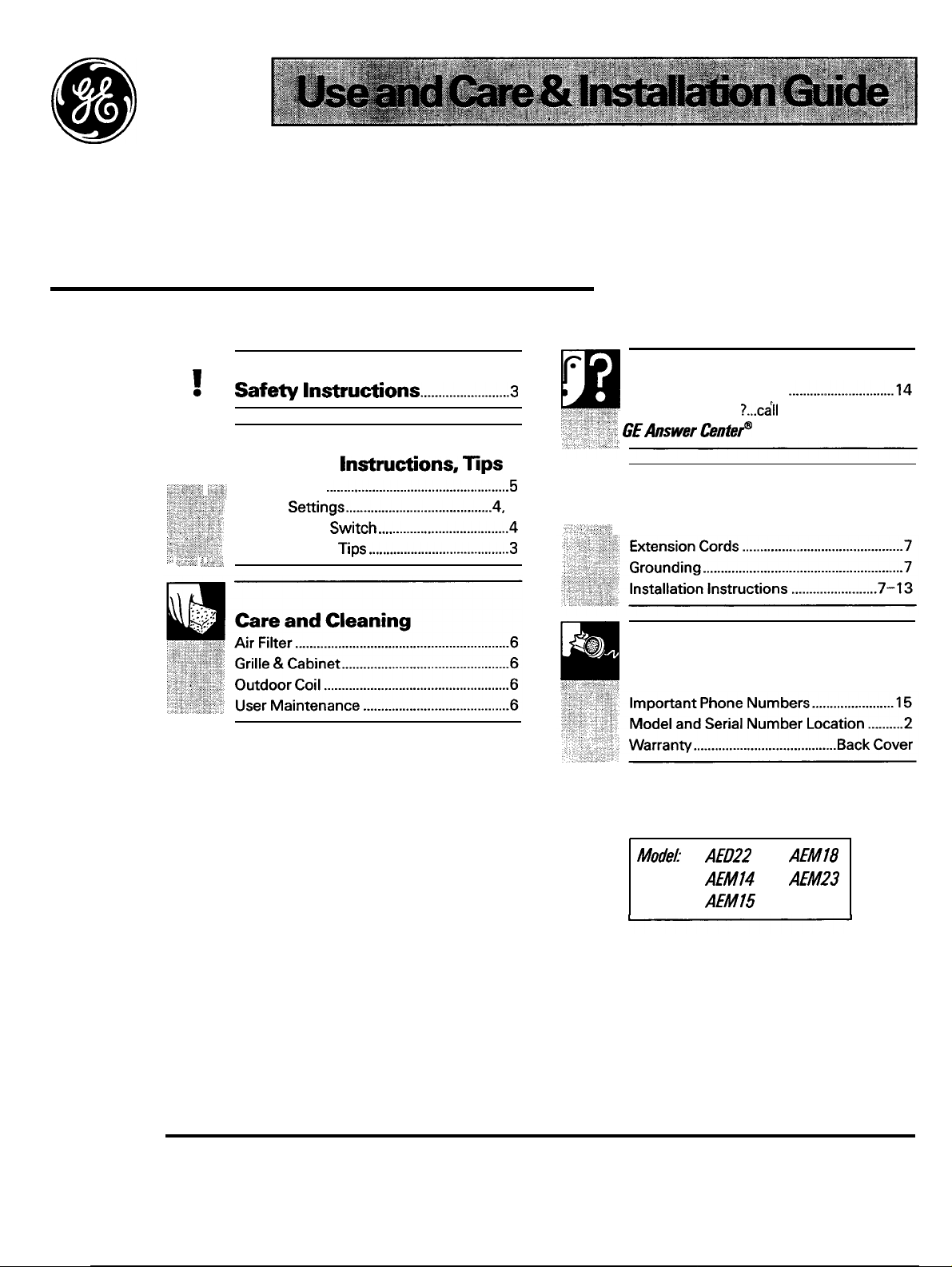
Installation
Electrical Requirements ...............................7
Consumer Services
Appliance Registration .................................2
..................15
GE Appliances
Page 2
US
YOU
Before using your air
conditioner, read
It is intended to help you operate
and
conditioner properly.
Keep it handy for answers to your
questions.
If you don’t understand something
or need more help, write (include
your phone number):
Consumer Affairs
GE Appliances
Appliance Park
Louisville, KY 40225
your new air
book
Write
model and
serial numbers.
You’ll find them on a label above
the power cord at its exit point
from the case.
These numbers are
Consumer Product Ownership
Registration Card that came with
your air conditioner. Before
sending in this card, please write
these numbers here:
Serial
Use these numbers in any
correspondence or service calls
concerning your air conditioner.
YOU
on the
a damaged
air conditioner...
Immediately contact the
(or builder) that sold you the
air conditioner.
Save time and money,
Before you request
service...
Cheek the Problem Solver
of this guide. It lists causes of
minor operating problems that you
can correct yourself.
To obtain service, see the Consumer Services page in
the back of this guide.
We’re proud of our service and want you to be
pleased. If for some reason you are not happy with the
service you
further help.
contact the people who serviced your
appliance. Explain why you are not pleased. In most
cases, this will solve the problem.
here are three steps to follow for
if you are still not pleased, write
details-including your phone number—to:
Manager, Consumer Relations
GE Appliances
Appliance Park
Louisville, KY 40225
if your problem is still not resolved, write:
Major Appliance Consumer
Action Panel
20 North
Chicago,
the
2
Page 3
● Keep the air filter clean.
●
For most efficient cooling, keep the Ventilation
Control in the CLOSED position except when you
want to exhaust air, smoke or odors from the room.
●
Don’t let the room get too hot.
turn the unit on before the room heats up.
possible,
heat
is “stored up” in walls, furniture,
your air conditioner takes longer to produce the
desired comfort condition.
●
Keep windows and doors closed. Cool, dry air
escapes when they’re open.
●
Keep furnace floor registers and cold air returns
closed. Cold air can easily escape through them.
●
Don’t let drapes or
block the front of the
unit and restrict air flow when it is operating.
●
It’s best to operate your air conditioner at high
speed during extremely hot weather.
●
Keep the outdoor coil clean.
●
the air conditioner off before vacations or
extended absences from home.
3
Page 4
CONTROLS
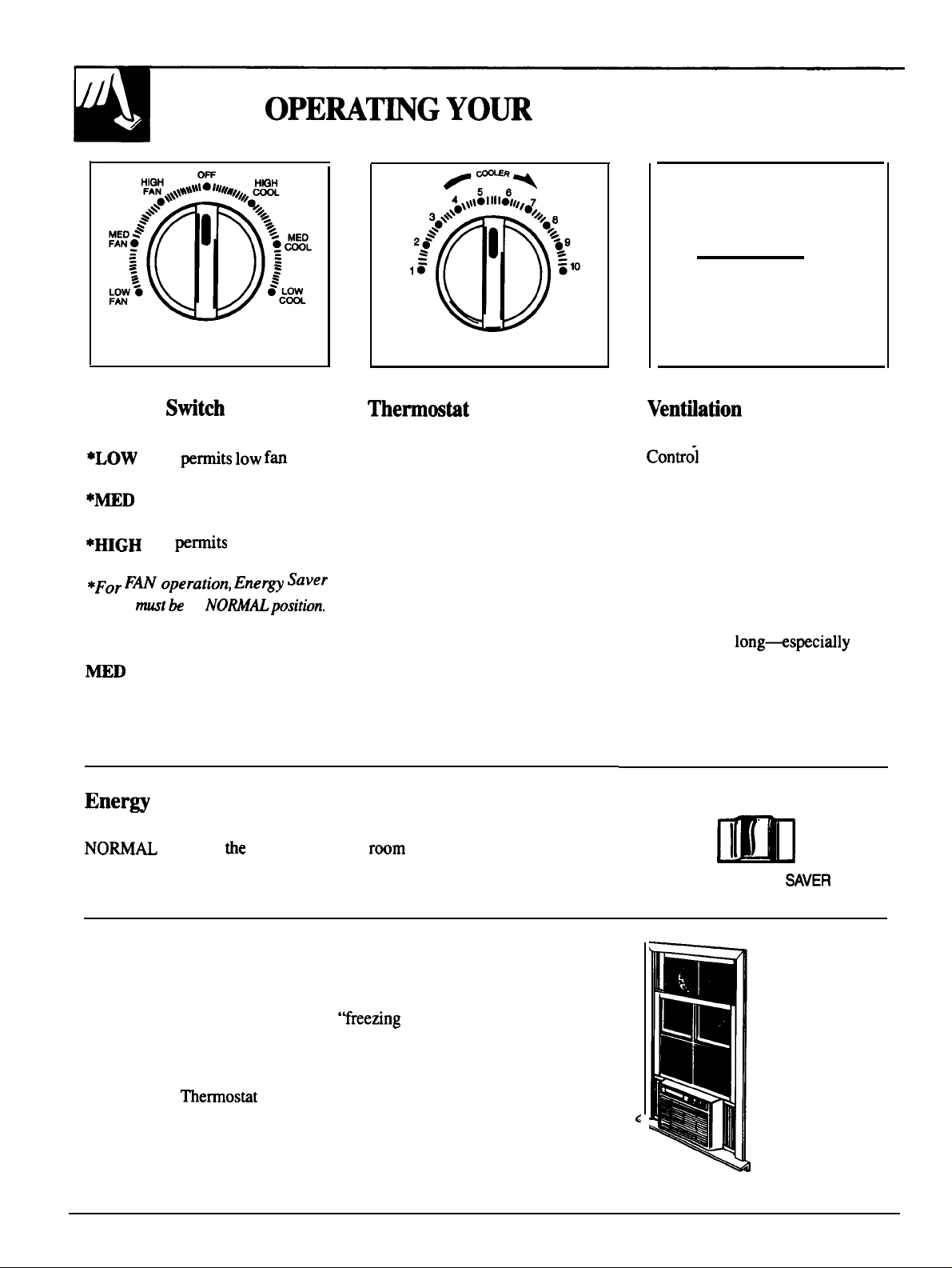
SELECTOR
Selector
OFF turns air conditioner off.
speed
operation
FAN permits medium fan
speed operation without cooling.
speed operation without cooling.
Switch
LOW COOL permits cooling with
low fan speed operation.
COOL permits cooling with
medium fan speed operation.
HIGH COOL permits cooling
with high fan speed operation.
without cooling.
in
high fan
THERMOSTAT
Control
When you turn the Thermostat
Control to the desired setting, the
thermostat will automatically
control the temperature of the
indoor air. The higher the number
selected, the cooler the indoor air
will be.
OPEN
❑
CLOSED
VENTILATION
Control
When you move the Ventilation
to CLOSED, the vent door
is closed and only the air inside the
room will be circulated and
conditioned. Moving the control to
OPEN opens the vent door,
allowing a small amount of indoor
air to be exhausted from the room.
However, cooling effectiveness is
reduced when this control is set at
OPEN, so we suggest you don’t
keep it there
hot, humid weather.
in
Saver Stitch
The Energy Saver Switch controls the fan operation. When it’s in the
position,
in the SAVE position, the fan will automatically cycle on and off with the
compressor.
fan will circulate
air continuously. When it’s
Freezing up
If you notice that your air conditioner is not cooling as it should, it may be
that ice has formed on the cooling coils. The ice blocks air flow and stops
the unit from cooling the room. This
that most often occurs at night when the Thermostat is set at a higher
number and the Selector is set on LOW COOL.
To correct the condition, set the Selector at HIGH FAN or HIGH COOL
and move the
to the warmest setting.
up” is a temporary condition
NORMAL
SAVE
ENERGY
Outside air
temperature
dropping
Page 5
For Normal
1.
Set the Selector Switch at
HIGH COOL.
2. Set the
desired number
good
temperature is not satisfactory
after a reasonable time, set
Control at a higher
number for a cooler room or at a
lower number for a warmer room.
Control at the
5-7 is a
position). If room
3.
Set the Energy Saver Switch at
fan operation or at SAVE position
to automatically cycle the fan on
and off with the compressor.
4. Set the Ventilation Control
at CLOSED except for brief
periods when you want to
exhaust room air to the outside.
For Quieter Operation
1.
Set the Selector Switch at LOW COOL position.
2.
the
When the
the Fan is set on low speed, moisture may freeze on
the coils and prevent the unit from cooling. If this
happens, set the
Control to a lower number.
Control to the desired number.
Control is set on 9 or 10
at high speed and set the
position for continuous
3. Set the Ventilation Control at CLOSED.
4. Set the Energy Saver Switch at the
position.
When the Energy Saver Switch is at the SAVE
position, changes in the sound level maybe more
noticeable than when it’s at
For Maximum
1.
Set the Selector Switch at
HIGH COOL.
2.
3. Set the Ventilation Control
4. Set the Energy Saver Switch
the
to 10.
at CLOSED.
at the
Control
position.
position.
For
During the cooler evening hours, we recommend that
you set
quiet operation and the
(5 or 6). Set the Ventilation
Energy Saver Switch at NO
Operation
Switch at LOW COOL for very
Control at mid-range
at CLOSED and the
or SAVE position.
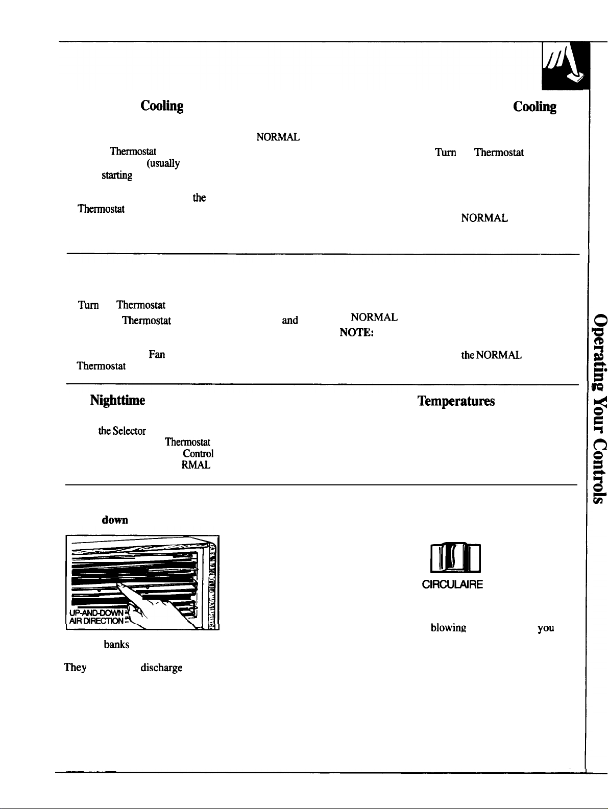
To Adjust Air Direction
Up and
Separate
are controlled by fingertip pressure on the louvers.
regulate air
straight out.
of up-and-down air direction louvers
upward, downward or
For Extreme
For greatest economy and best performance, we
suggest you set the Selector Switch at HIGH COOL
in extremely hot weather.
Side to side
OFF
Some models have a Circulaire Switch. For fixed
side-to-side air direction, slide the Circulaire Switch
to ON until the air is
want, then move it to OFF.
For continuous side-to-side air circulation, set the
Circulaire Switch to ON and leave it there.
For models without the Circulaire feature, adjust the
side-to-side air direction by using the levers on both
sides of the louvers. Pull the lever outward as you
move it side to side.
ON
in the direction
-
5
Page 6
Maintenance
off
remove
plug from the
& Cabinet
Wipe the front grille with a clean cloth lightly
dampened with mild liquid
Wash the cabinet with mild soap or detergent and
lukewarm water.
detergent.
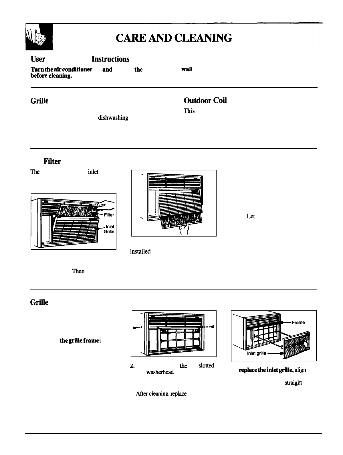
Air
air filter behind the
should be washed at least every 30
days or as often as it needs cleaning.
grille
outlet
coil on the outdoor side of the unit should be
checked periodically and cleaned if clogged with dirt
or soot from the atmosphere. If extremely soiled, it
may need to be steam cleaned, a service available
through your GE service outlet.
Vacuum the filter on the dusty
side to remove light dust. Wash
the filter, cleaner side up, under
gently flowing water to wash out
accumulated dust and lint. If the
filter is very dirty, use a mild
household detergent in the wash
water.
before replacing it.
the filter dry thoroughly
To remove the filter,
upper part of the inlet grille and
pull toward you.
filter up and out.
grasp the
pull the
Frame Removal
The grille frame can be removed
for more thorough cleaning or
to make the model and rating
information easier to read.
To remove
1.
Grasp the upper part of the
inlet grille and pull it away
from the frame. Do the same to
the lower part of the inlet grille.
Then pull the grille straight out
and off the frame.
NOTE:
can pull the lower part of the inlet
grille toward you and pull the filter
down and out.
3.
If the air conditioner is
high through a wall, you
Remove and save
hex
two side retaining screws that
hold the frame to the chassis.
Use a magnetic-tipped screwdriver
to attach the frame with the four
screws removed in step 2.
two S1ON
screws and the
the frame.
To repbce
large tabs on the grille with the slots
on the frame and push
until the grille snaps into pi=.
the
on
6
Page 7
OWNER:
Keep these instructions for future use.
Electrical
HOW
FOR PERSONAL
The
fuse or circuit breaker.
The power cord on these models has a
(grounding) plug
(grounding) wall outlet (Fig.
of electric shock hazard from these appliances.
Where a standard
prong wall outlet is
encountered, it is your
personal responsibility
and obligation to have it
replaced with a properly
grounded
wall outlet.
models require a
outlet protected with a
that
mates with a standard
THIS APPLIANCE
60
time delay
minimize the possibility
PREFERRED
METHOD
INSURE PROPER
Fig.
GROUND EXISTS
BEFORE USE
Please Read Carefully
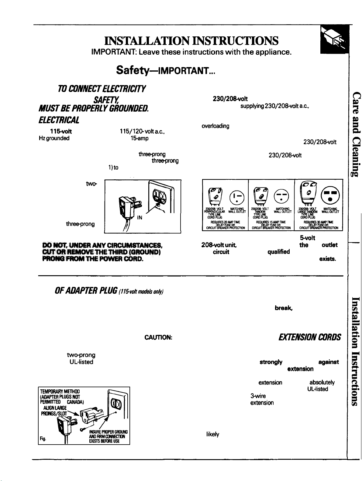
The
branch circuit
with a time delay fuse or circuit breaker. This is
recommended for best performance and to prevent
house wiring circuits, which could cause a
possible fire hazard from overheating wires.
The power cord on these models has a
perpendicular, tandem or large tandem-type plug that
mates respectively with a
tandem or large tandem-type wall outlet. These types
of outlets are available at most hardware stores.
Whether your air conditioner is a 11
and
is any doubt as to whether a proper ground
checked by a qualtied electrician if there
models require their own single
it is important to have
protected
perpendicular,
wall
or a 230/
USE
Because of potential safety
hazards under certain conditions,
we strongly recommend
against use of an adapter plug.
However, if you still elect to use
an adapter, where local codes
permit, a temporary connection
may be made to a properly
grounded
by use of a
(Fig. 2) available at most local
hardware stores.
M~OD
WGS
2
wall outlet
adapter
The larger slot in the adapter must
be aligned with the larger slot in
the wall outlet to provide proper
polarity in the connection of the
power cord.
Attaching the adapter
ground terminal to wall outlet
cover screw does not ground the
appliance unless cover screw is
metal, and not insulated, and wall
outlet is grounded through house
wiring. You should have the circuit
checked by a qualified electrician
to make sure the outlet is properly
grounded.
When disconnecting the power
cord from the adapter, always
hold the adapter with one hand. If
this is not done, the adapter
ground terminal is very
break with repeated use.
to
Should the adapter ground
terminal
appliance until a proper ground
has again been established.
DO NOT USE the
USE OF
Because of potential safety
hazards under certain renditions,
we atrong~ recommend
the use of an etiension cord.
However, if you still elect to use
an
necessary that it be a
carrying rating of the cord in
amperes be equal to or greater than
the branch circuit size shown on the
rating nameplate of the appliance.
cord, it is
grounding type appliance
cord and that the current
7
Page 8
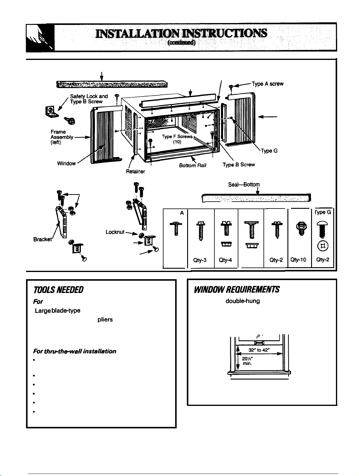
Window Sash Seal
Top Rail
I
Foam
Gasket
Frame
Assembly
(right)
Screw
Filler
Panel
Type C Screws ,
and Locknuts
‘ ‘
o
Window
support
Sill
Angle Bracket
window installation
●
blad~type screwdriver
● Adjustable wrench or
● Rule or tape measure
●
Sharp knife or razor blade
Side
Type D Bolt
● Pencil
Type A
@-2
Rail to Unit
.,,.,7
Type B
.
Type C
.
Type D
Type E
Type F
@-2
●
Standard doubl~hung window with actual
opening width and minimum vertical opening.
✎
From bottom of sash to stool as follows
(depending on your model):
All the tools above
(except knife or razor blade) plus
Magnetic stud finder (optional)
Tin snips (optional)
Hammer
Chisel
● Handsaw
● Level
●
Caulking gun
Concrete saw
(if installing through a masonry wail)
8
NOTE: All supporting parts should be secured
to firm wood, masonry or metal.
Page 9

A l/2’’ clearance below the window
stool is required.
If the storm window frame does not allow this
clearance, attach a 1
along the entire length of the window opening,
flush with the back side of the stool, or remove
the storm window for the air conditioning season.
or
Storm
Window Frame
or Other
strip of wood
Sash
2.
1. Attach foam gasket to top rail as shown.
2. Install top rail and side retainers to cabinet
as shown, using 10 Type F screws.
AND SIDE
Remove the side retaining screws from
either side of the case.
Slide chassis from cabinet by holding with left
hand while pulling on handle at bottom front of
unit. Be careful of sharp edges on the coil fins.
your unit has corrugated packing material inside
the cabinet it must be removed. Do not remove
the foam pads inside the cabinet Foam blocks on or
around the compressor are to be removed. See note
attached to compressor for which blocks to remove.
NOTE: Handle is NOT intended for lifting the
unit. It is only for sliding the chassis out of the
cabinet for cleaning or maintenance.
9
Page 10

3. ASSEMBLE WINDOWFILLER
Place cabinet on floor, bench or table.
Plastic
Frame
3. Shift cabinet left or right as needed to line up
center of cabinet on center line marked on stool.
r
2. Slide the “
-
1
section of the window filler panel
into the panel retainer on the side of the
cabinet as shown above. Do both sides.
3. Insert top and bottom legs of the window filler
panel frame into
the channel in the top support
angle and bottom rail. Do both sides.
Plastic
Air Condition
Frame
Linking
Screw
Hole
Window Filler
Panel
4. Insert two Type A screws into holes in the top
leg of the filler panel frame. Do not
should slide easily.
4. LOCATE
Open window and mark center ofwindowstool.
2. Place cabinet in window with bottom stool
angle firmly seated over window stool as
shown. Bring window down temporarily
behind top rail to hold cabinet in place.
Fasten cabinet to window stool with 2 Type B
screws. (You may want to drill pilot holes.)
5.
C Screws and
(2 required for each support bracket)
~/
LEFT
●
0
(1 required for each support bracket)
Sill
Hold each support
bracket flush
against outside of
sill and tight to
bottom of cabinet
as shown. Mark
brackets at top
level of sill and remove them.
2. Assemble sill angle brackets to support
brackets at positions previously marked, as
shown. Hand tighten only—some adjustment
may be required later.
10
3. Install
brackets, with sill angle
brackets attached, to cabinet as shown.
4. Tighten all 6 bolts and screws securely.
Page 11
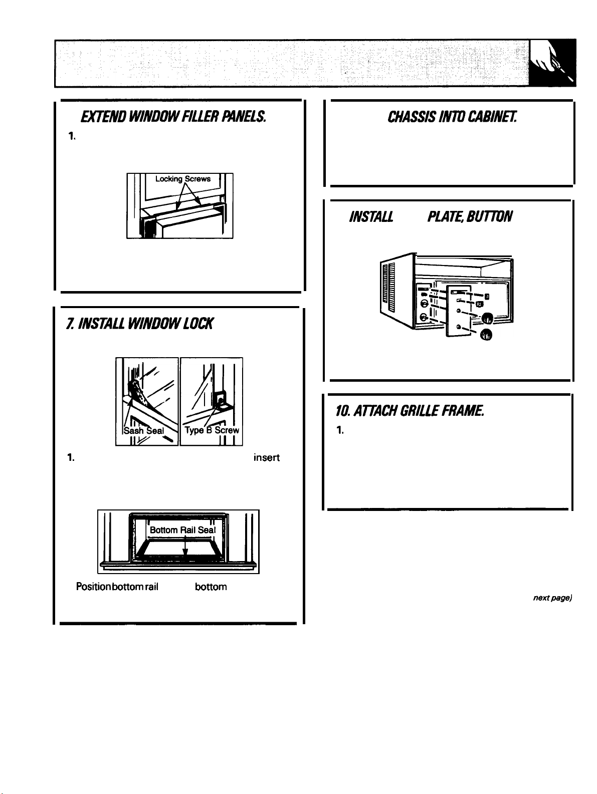
6.
8. SLIDE
Carefully raise window to expose filler panel
locking screws. Loosen screws (Type A) so
panels slide easily.
2. Extend panels to fill window opening
completely and tighten locking screws on top.
3. Close window behind top rail.
AND SASH SEAL.
Y
/
Be sure handle at bottom of unit is up. Then lift
chassis and carefully slide it into cabinet. Do not
push on controls or finned coils. Make sure
chassis is firmly seated toward rear of cabinet.
9.
AND KNOBS.
If dial plate has a protective film, peel the film off
carefully.
DIAL
I
@~
Do not scratch the surface of the plate.
Trim sash seal to fit window width and inseti
into space between upper and lower sashes.
2. Attach right angle safety lock with Type B
screw as shown.
3.
with front edge of rail and in contact with
side seals.
seal on
rail flush
Remove inlet grille (see Care and
Cleaning section).
2. Attach grille frame to unit
(see page 13, step 6).
3. Reinstall inlet grille (see Care and
Cleaning section).
(continued
11
Page 12
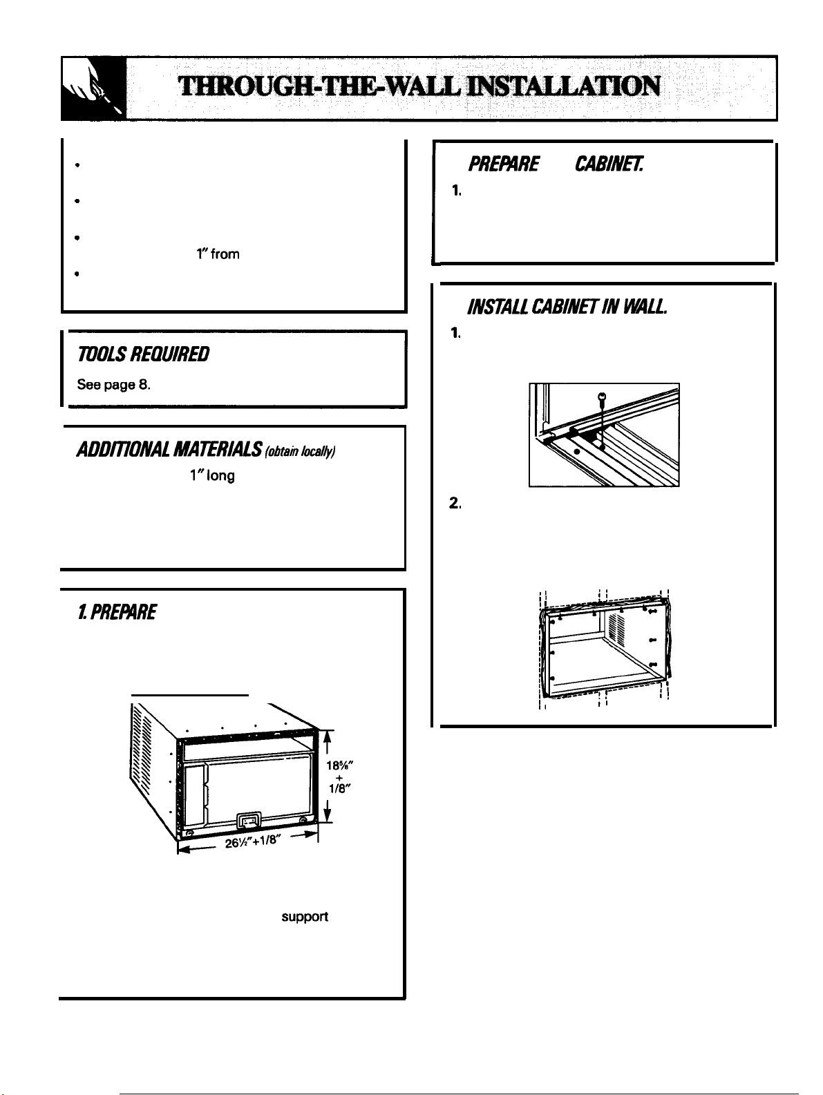
The cabinet may be installed through the wail in
both existing buildings and new construction.
The side louvers must project on the outdoor
side of the wall.
The room side of the cabinet must project into
the room at least
the finished wall.
The cabinet must be installed level from side to
side and with a 3/8” tilt from front to rear.
MAERIALS
● 2 wood screws,
● 10 #10 wood screws, 1“ long
●
1 tube high grade caulking compound
●
Lintel, if required, to support bricks or blocks
above opening.
2. PREMRE WE CABINfl
Remove chassis from cabinet.
2. With caulking compound or electrical tape,
seal 10 holes provided in cabinet for top rail
and side retainers not used in this installation.
3.
Place the cabinet into the wall opening with
the bottom rail resting firmly on the bottom
of the wood frame.
1“ long wood screws obtained locally.
3. Secure cabinet to wooden frame with ten # 10
1“ long screws or nails obtained locally. If frame
is oversize, use shims to eliminate distortion.
WALL OPENING
1. Determine size of opening. Measure width
and height of cabinet and add 1/8” to each
dimension.
2. Choose the wall opening location. Be sure
wall receptacle is (or will be) installed nearby.
3. Make the opening. Frame it to
the
weight of the air conditioner. Add metal flashing
over bottom of frame opening and 1“ up on sides
to reduce the possibility of condensate entering
the area between the inner and outer wall.
,--
---
-----
-------- , ,
,1
12
Page 13
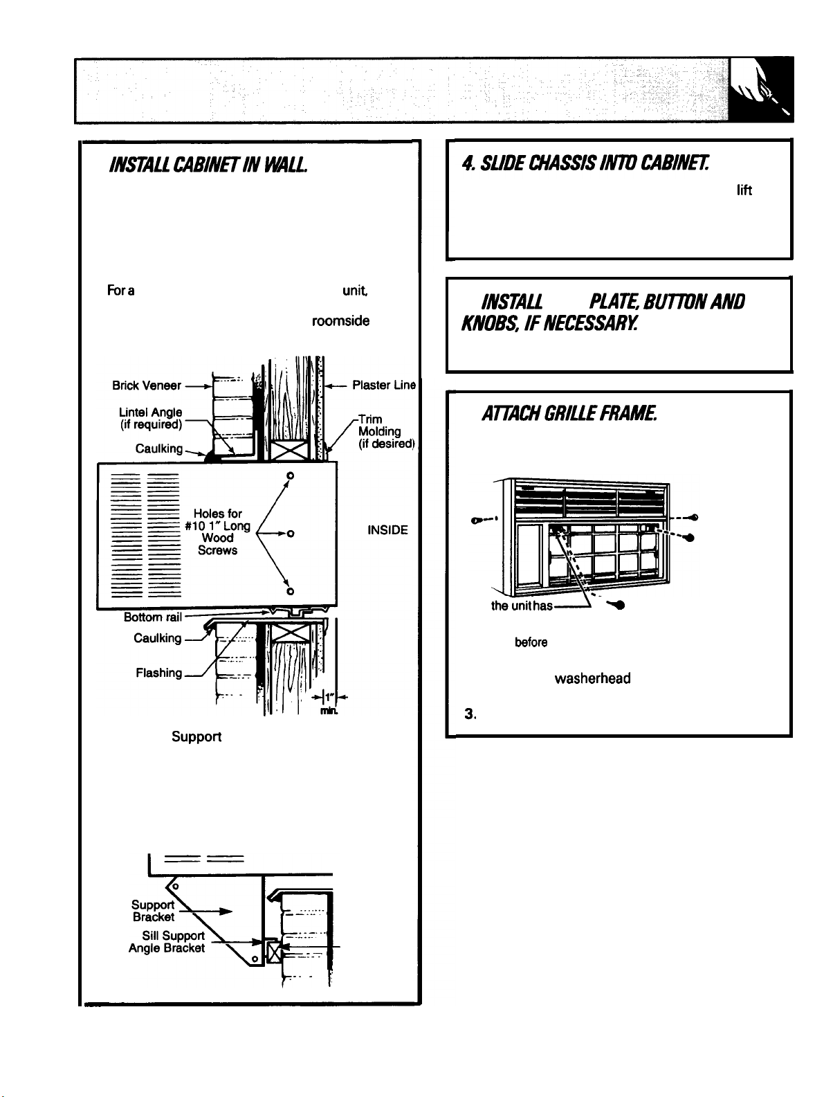
3.
(continued)
4. Caulk all four sides on the outdoor side of
cabinet to prevent moisture from getting
through to the interior wall. Use of flashing (a
piece of aluminum or galvanized steel available
at most hardware stores) will further prevent
moisture from getting into interior walls.
5.
tight seal along the bottom of the unit
caulk around the bottom rail. Install wood trim
molding (obtained locally) around
projection of cabinet if desired.
Be sure handle at bottom of unit is up. Then Iifi
chassis and carefully slide it into cabinet. Do not
push on controls or finned coils. Make sure
chassis is firmly seated toward rear of cabinet.
5.
DIAL
See page 11, step 9.
6.
1. Remove the inlet grille from the grille frame.
(See page 6.)
TypeG Screw
Optional: Suppon brackets maybe used.
Installation of brackets are recommended for
walls under 5“.
Refer to Step 5 of window installation for
assembly of support brackets. A wooden strip
nailed to the outside wall should be used in
conduction with the sill support angle brackets.
Wooden
strip
-
‘
If
a screw in this
location, remove and discard the
screw
installing the grille frame.
Type E Screw
2. Attach the grille frame to the unit with two
Type E Hex
screws and with two
Type G side retaining screws as shown above.
13
Page 14

USE THIS PROBLEM SOLVER
CAUSE
need more help... call,
GE Answer
S00.626.2000
information
14
free:
Page 15
Be
With the purchase
or assistance from GE,
/dome
AGE consumer service professional will provide expert repair service,
scheduled at a time that’s convenient for you. Many GE Consumer Service
locations offer you
convenience
Our
repairs can be handled in just one visit.
Whatever your question about any GE major appliance, GE Answer Center”
information service is available to help. Your call–and your question-will be
answered prompdy and courteously. And you can call any time. GE Answer
Center” service is open 24 hours a day, 7 days a week.
a.m. to
technicians know your appliance inside
p.m. weekdays,
GE appliance, receive the
there. All you have to do is dl–toll-free!
today or tomorrow, or at your
a.m. to
p.m. Saturdays).
and out–so most
that
ever need
Upon request, GE will provide
Braille controls for a
appliances, and a brochure to call 800-TDD~EAC (80043
assist in planning a barrier-free information or service.
kitchen for persons with limited
mobility. To obtain
free of charge, call 800.626.2000.
You can have the
after your warranty expires. Purchase a GE contract while your warranty is
in effect and you’ll receive a substantial discount. With a multiple-year contract,
you’re assured of future service at today’s prices.
can have
their
47,000
fully warranted.
are accepted.
needed
home. The GE parts system provides access to over
secure feeling that GE Consumer Service will still be there
to
or accessories sent
VISA, MasterCard and Discover cards
tick own appliances
SpecialNeeds...
Consumers with impaired hearing or speech who have
of GE access to a
items,
User
to
cover prwedures intended to
service
improper
or a conventional teletypewriter may
instructions
Caution must be
to request
in this
performed
be referred to
since
unsafe operation.
Page 16
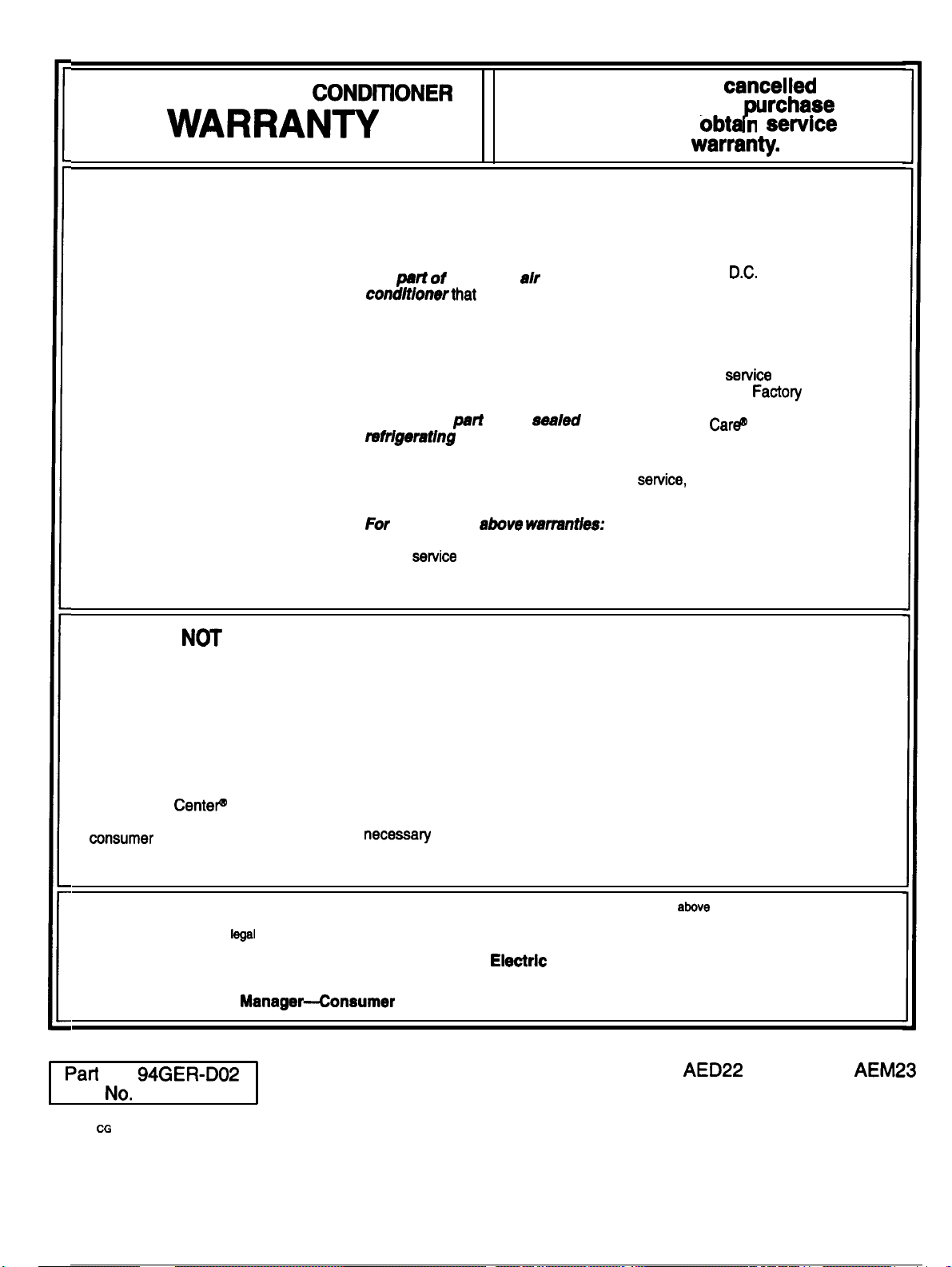
YOUR GE ROOM AIR
Staple sales slip or
here. Proof of original
is needed to
n
under warran~.
check
date
WHAT IS COVERED
WHAT IS
●
Service trips to teach you how to
use the product.
Read your Use and Care material.
If you then have any questions
about operating the product,
please contact your dealer or our
Consumer Affairs office at the
address below, or call, toil free:
GE Answer
800.626.2000
information service
COVERED
FULL ONE-YEAR WARRANTY
For one year from date of original
purchase, we will provide, free of
charge, parts and service labor in
your home to repair or replace
any
the room
fails because
of a manufacturing defect.
FULL FIVE-YEAR WARRANTY
For five years from the date of
original purchase, we will provide,
free of charge, parts and service
labor in your home to repair or
replace any
of the
compressor, condenser,
evaporator and all connecting
tubing) that fails because of a
manufacturing defect.
each of the
warrsntbs:
Transportation expense to and
from a
shop and shop
service labor if required will be free
of charge.
●
Improper installation.
If you have an installation
problem, or if the air conditioner is
of improper cooling capacity for the
intended use, contact your dealer
or installer. You are responsible for
providing adequate electrical
connecting facilities.
●
Replacement of fuses or resetting
of circuit breakers.
●
In commercial locations labor
to move the unit to a
location where it is accessible for
service by an individual technician.
This warranty is extended to
the original purchaser and any
succeeding owner for products
purchased for use in the 48
mainland states, Hawaii and
Washington,
In Alaska the
warranty is the same except that it
is LIMITED because you must pay
to ship the product to the service
shop or for the service technician’s
travel rests to your home.
Ail warranty
will be
provided by our Factoy Service
Centers or by our authorized
Customer
servicers during
normal working hours.
Should your appliance need
during warranty period
or beyond, call 1-800-GE-CARES
(1-800-432-2737).
●
Failure of the product resulting
from modifications to the product or
due to unreasonable use including
failure to provide reasonable and
necessary maintenance.
●
Failure due to corrosion on
models not corrosion-protected.
●
Damage to product caused
by improper power supply voltage,
accident, fire, floods or acts of God.
WARRANTOR IS NOT
RESPONSIBLE FOR
CONSEQUENTIAL DAMAGES.
Some
may not apply to you. This warranty gives you specific legal rights, and you may also have other rights which vary from state to state.
To know what your
No. 94GER-D02
Pub
12-93
49-7290
states
do not allow the exclusion or limitation of incidental or consequential damages, so the
rights are in your state, consult your local or state consumer affairs office or your state’s Attorney General.
Warrantor: General Electrlc Company
If further help Is needed concerning this warranty, write:
Affairs, GE Appliances, Louisville, KY 40225
limitation or exclusion
AEM15
AEM14 AEM18
Printed in the United States
 Loading...