

GE ADT521PGF4BS, GDF520PGD4CC, GDF510PGD4BB, GDF520PGD4WW, GDT530PGD4WW Installation Instructions Manual
...Page 1
Installation Instructions
Built-in Dishwasher
Ifyou have questions, call 800.GE.CARES(800.432.27371or visit our Website at: GEAppliances.com.
InCanada, please call 1.800.561.3344or visit www.geappliances.ca
BEFOREYOU BEGIN
Read these instructions completely and
carefully.
IM PORTANT - Observeallgoverningcodesand
ordinances.
. Note to Installer - Be sure to leave these instructions for the
consumer's and local inspector's use.
Note to Consumer - Keep these instructions with your
Owner's Manual for future reference.
Skill Level - Installation of this dishwasher requires
basic mechanical, electrical and plumbing skills. Proper
installation is the responsibility of the installer. Product
failure due to improper installation is not covered under
the GE Appliance Warranty. See warranty information.
Completion Time - 1 to 3 Hours. New installations require
more time than replacement installations.
READ CAREFULLY.
KEEP THESE INSTRUCTIONS.
IM PORTANT - The dishwasherMUST be installed
to allow for future removal from the enclosure if service is
required.
Care should be exercised when the appliance is installed or
removed, to reduce the likelihood of damage to the power
supply cord.
If you received a damaged dishwasher, you should immediately
contact your dealer or builder.
Optional Accessories - Seethe Owner's Manual for available
custom panel kits.
FOR YOUR SAFETY
Read and observe all CAUTIONSand WARNINGSshown
throughout these instructions. While performing
installations described in this booklet, gloves, safety glasses
or goggles should be worn.
Printedin the UnitedStates 3"1-3"1506-3 04-"13 GE
Page 2
Installation Preparation
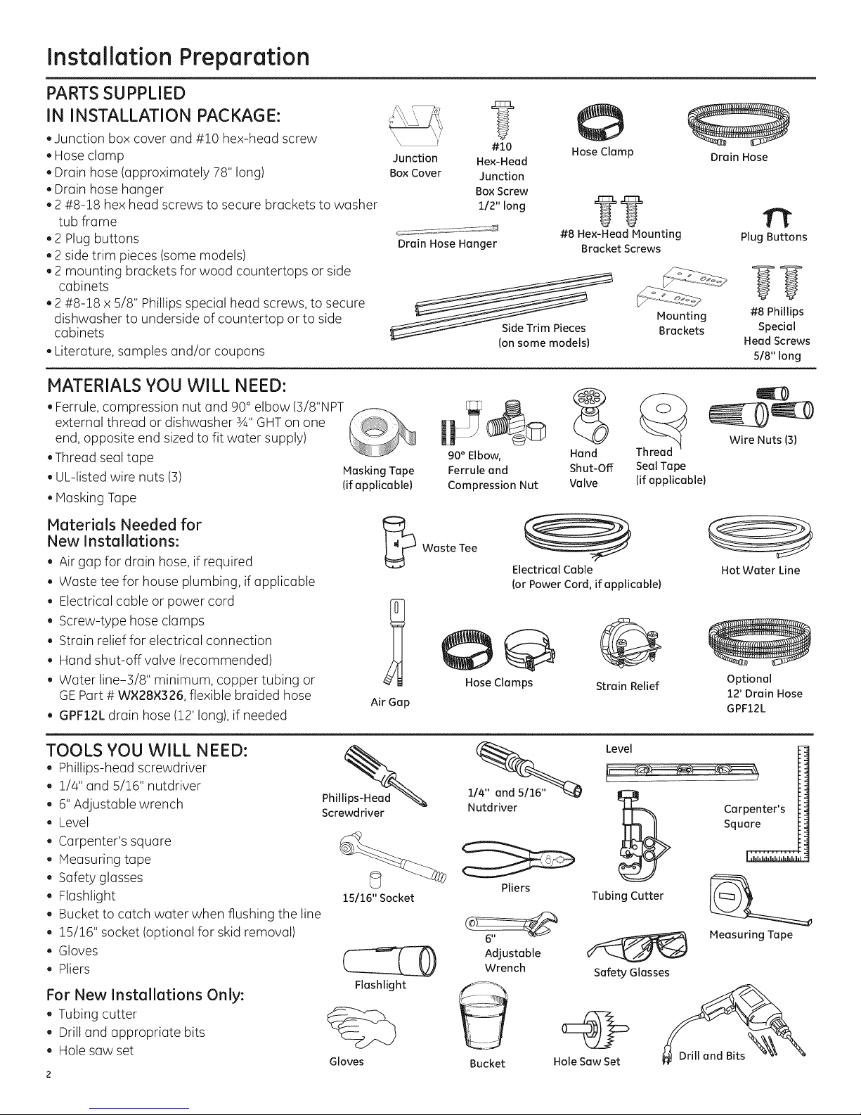
PARTS SUPPLIED
IN INSTALLATION PACKAGE:
. Junction box cover and #!0 hex-head screw
. Hose clamp
. Drain hose (approximately 78" long)
. Drain hose hanger
.2 #8-!8 hex head screws to secure brackets to washer
tub frame
.2 Plug buttons
.2 side trim pieces (some models)
.2 mounting brackets for wood countertops or side
cabinets
.2 #8-18 x 5/8" Phillips special head screws, to secure
dishwasher to underside of countertop or to side
cabinets
Literature, samples and/or coupons
MATERIALS YOU WILL NEED:
. Ferrule, compression nut and 90 ° elbow (3/8"NPT
external thread or dishwasher sA"GHT on one
end, opposite end sized to fit water supply)
Thread seal tape
. UL-listed wire nuts (3) Masking Tape
(if applicable)
Masking Tape
Junction
Box Cover
Drain Hose Hanger
?
#10
Hex-Head
Junction
Box Screw
112" long
(onsome models)
90° Elbow,
Ferrule and
Compression Nut
Hose Clamp
??
#8 Hex-Head Mounting
Bracket Screws
Mounting
Brackets
Hand
Shut-Off
Valve
Seal Tape
(ifapplicable)
Drain Hose
n
Plug Buttons
#8 Phillips
Special
Head Screws
5/8" long
Wire Nuts (3)
Materials Needed for
New InstaiJations:
. Air gap for drain hose, if required
. Waste tee for house plumbing, if applicable
. Electrical cable or power cord
Screw-type hose clamps
Strain relief for electrical connection
Hand shut-off valve (recommended)
Water line-3/8" minimum, copper tubing or
GEPart # WX28X326, flexible braided hose
GPF12Ldrain hose (12' long),if needed
TOOLS YOU WILL NEED:
. Phillips-head screwdriver
1/4" and 5/16" nutdriver
6"Adjustable wrench
Level
, Carpenters square
, Measuring tape
Safety glasses
Flashlight
Bucket to catch water when flushing the line
15/16" socket (optional for skid removal)
Gloves
Pliers
For New Installations Only:
Tubing cutter
Drill and appropriate bits
Hole saw set
Phill2ad_
Screwdriver
15/16" Socket
Flashlight
Gloves
Air Gap
Waste Tee
Electrical Cable
(or Power Cord, if applicable)
Hose Clamps
Nutdriver
Pliers
Adjustable
Wrench
Bucket
Strain Relief
Level
Tubing Cutter
Safety Glasses
Hole Saw Set
Hot Water Line
Optional
12' Drain Hose
GPF12L
Carpenter's
Square
Measuring Tape
Page 3
Installation Preparation
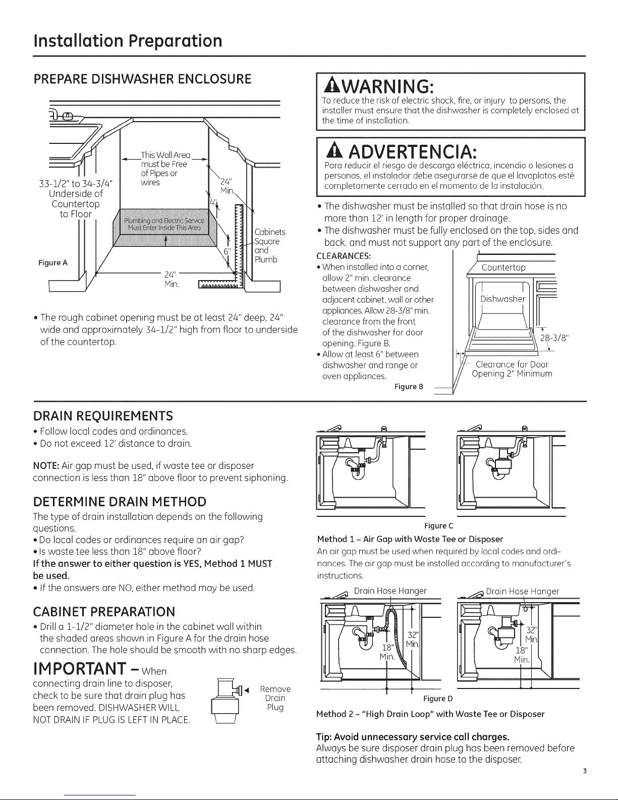
PREPARE DISHWASHER ENCLOSURE
ThisWallArea
mustbe Free
of Pipesor
33-1/2" to 3/4-3/4"
Underside of
Countertop
to Floor
Figure A
. The rough cabinet opening must be at least 2/4"deep, 2/4"
wide and approximately 34-1/2" high from floor to underside
of the countertop.
wires
£abinets
Square
and
Plumb
kWARNING:
Toreducethe riskofelectricshock,fire,or injury to persons,the
installermustensurethat the dishwasheris completelyenclosedat
thetime of installation.
A ADVERTENCIA:
Parareducirelriesgode descargael@ctrica,incendioolesionesa
personas,elinstaladordebeasegurarsedeque el lavaplatosest@
completamentecerradoen el momentadelainstalaci6n.
The dishwasher must be installed so that drain hose is no
more than 12' in length for proper drainage.
The dishwasher must be fully enclosed on the top, sides and
back, and must not support any part of the enclosure.
CLEARANCES:
• When installed into a corner,
allow 2"rain. clearance
between dishwasher and
adjacent cabinet, wall or other
appliances.Allow 28-5/8" rain.
clearance from the front
of the dishwasher for door
opening. Figure B.
Allow at least 6" between
dishwasher and range or
oven appliances.
FigureB
L
J Countertop
/ Clearancefor Door
Opening2"Minimum
DRAIN REQUIREMENTS
, Follow local codes and ordinances.
Do not exceed 12' distance to drain.
NOTE:Air gap must be used, if waste tee or disposer
connection is less than 18" above floor to prevent siphoning.
DETERMINE DRAIN METHOD
The type of drain installation depends on the following
questions.
. Do local codes or ordinances require an air gap?
. Iswaste tee less than 18"above floor?
If the answer to either question is YES,Method 1 MUST
be used.
. If the answers are NO,either method may be used.
CABINET PREPARATION
, Drill a 1-1/2" diameter hole in the cabinet wall within
the shaded areas shown in Figure Afor the drain hose
connection. The hole should be smooth with no sharp edges.
IMPORTANT -When
connectingdrainlinetodisposer,
checktobesurethatdrainplughas
beenremoved.DISHWASHER WILL
NOT DRAIN IFPLUG ISLEFTINPLACE.
Drain
Plug
4 Remove
Figure C
Method I - Air Gap with Waste Tee or Disposer
Anairgap mustbe usedwhen requiredby local codesandordi-
nances.Theair gap must beinstalledaccordingto manufacturer's
instructions.
DrainHoseHanger
_Hanger
\
L
Figure D
Method 2 - "High Drain Loop" with Waste Tee or Disposer
Tip: Avoid unnecessary service call charges.
Always be sure disposer drain plug has been removed before
attaching dishwasher drain hose to the disposer.
Page 4
Installation Preparation
PREPARE ELECTRICAL WIRING
WARNING:
FORPERSONALSAFETY:Removehousefuseoropencircuit breaker
beforebeginninginstallation.Donot useanextensioncordor
adapter plugwiththis appliance.
ADVERTENCIA:
PARASEGURIDADPERSONAL:Quiteelfusibleoabra elinterruptor
de circuitosantesde comenzarlainstalaci6n.No utiliceun cable
de extensi6nounenchufeadaptador conesteartefacto.
Electrical Requirements
. This appliance must be supplied with !20V, 60 Hz.,and
connected to an individual properly grounded branch circuit,
protected by a 15- or 20-ampere circuit breaker or time-delay
fuse.
. Wiring must be 2 wire with ground and rated for 75°C(176%).
. If the electrical supply does not meet the above requirements,
call a licensed electrician before proceeding.
Grounding Instructions-Permanent Connection
This appliance must be connected to a grounded metal,
permanent wiring system, or an equipment-grounding
conductor must be run with the circuit conductors and be
connected to the equipment-grounding terminal or lead on
the appliance.
Grounding Instructions-Power Cord Models
This appliance must be grounded. In the event of a malfunction
or breakdown, grounding will reduce the risk of electric shock
by providing a path of least resistance for electric current.
This appliance is equipped with a cord having an equipment-
grounding conductor and a grounding plug. The plug must
be plugged into an appropriate outlet that is installed and
grounded in accordance with all local codes and ordinances.
AWARNING:
Theimproper connectionof theequipmentgroundingconductor
can resultina riskofelectricshock.Checkwith a qualified
electricianor servicerepresentativeifyou are indoubt that
the applianceis properlygrounded.
/ I
_//_/_ _'_ Alternate
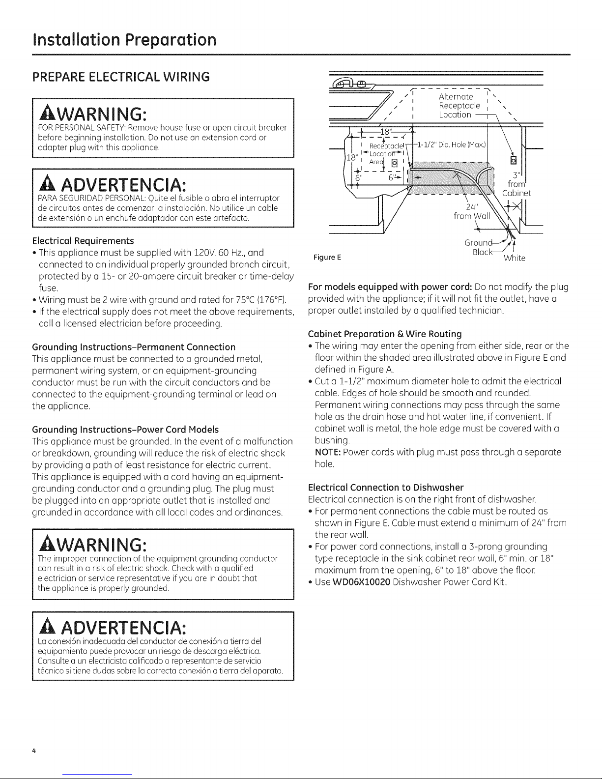
Figure E White
For models equipped with power cord: Do not modify the plug
provided with the appliance; if it will not fit the outlet, have a
proper outlet installed by a qualified technician.
Cabinet Preparation & Wire Routing
. The wiring may enter the opening from either side, rear or the
floor within the shaded area illustrated above in Figure Eand
defined in Figure A.
. Cut a 1-1/2" maximum diameter hole to admit the electrical
cable. Edgesof hole should be smooth and rounded.
Permanent wiring connections may pass through the same
hole as the drain hose and hot water line, if convenient. If
cabinet wall is metal, the hole edge must be covered with a
bushing.
NOTE:Power cords with plug must pass through a separate
hole.
Electrical Connection to Dishwasher
Electrical connection is on the right front of dishwasher.
. For permanent connections the cable must be routed as
shown in Figure E.Cable must extend a minimum of 24" from
the rear wall.
. For power cord connections, install a 3-prong grounding
type receptacle in the sink cabinet rear wall, 6" min. or 18"
maximum from the opening, 6" to 18" above the floor.
. Use WD06×lO020 Dishwasher Power Cord Kit.
_ Receptacle
Location
\
\
Cabinet
A ADVERTENCIA:
Laconexi6ninadecuadadelconductordeconexi6natierradel
equipamientopuedeprovocarunriesgodedescargael_ctrica.
Consultea unelectricistacalificadoorepresentantedeservicio
t_cnicositienedudassabrelacorrectaconexi6natierradelaparato.
Page 5

Installation Preparation
PREPARE HOT WATER LINE
NOTE:GErecommends copper tubing for the water line, but if
you choose to useflexible hose, use GE'sW×28×326, flexible
braided hose.
. The water supply line (3/8" copper tubing or flexible braided
hose) may enter from either side,rear or floor within the
shaded area shown in Figure F.
. The water supply line may pass through the same hole as the
electrical cable and drain hose.Or,cut an additional 1-1/2"
diameter hole to accommodate the water line. Ifpower cord
with plug is used,water line must not pass through power
cord hole.
ACAUTION:
Do not remove wood base until you are ready to install the
dishwasher. The dishwasher will tip over when the door is
opened if base isremoved.
PRECAUCION:
Noquite la base de madera hasta queest_ listo para instalar el
lavaplatos. Sisequita la base, el lavaplatos sevolcar6 cuando
se abra lapuerta.
il Shut-off_
Hot
From
Cabinet
Cabinet
FigureF
2" From Floor
Water Line Connection
. If using a flexible braided supply hose, labelthe hose with the
installation date to use as reference. Flexible braided hoses
should be replaced in 5 years.
. Turn off the water supply.
. Install a hand shut-off valve in an accessible location, such
as under the sink. (Optional, but strongly recommended and
may be required by local codes.)
. Water connection is on the left side of the dishwasher. Install
the hot water inlet line, using no less than 3/8" copper tubing
or aflexible braided hose. Route the line as shown in Figure F
and extend forward at least 19"from rear wall.
. Adjust water heater for 120°Fto 1/40°Ftemperature.
. Flush water line to clean out debris.
. The hot water supply line pressure must be20-120 PSI.
Turn page to begin dishwasher installation,
Page 6
Dishwasher Installation
STEP 1:PREPARATION
Locate the items in the installation package:
, Screws
Junction box cover
, Drain hose and clamp
, Mounting brackets
, Trim pieces (on some models)
, Drain hose hanger
, Owner's Manual
, Product samples and/or coupons
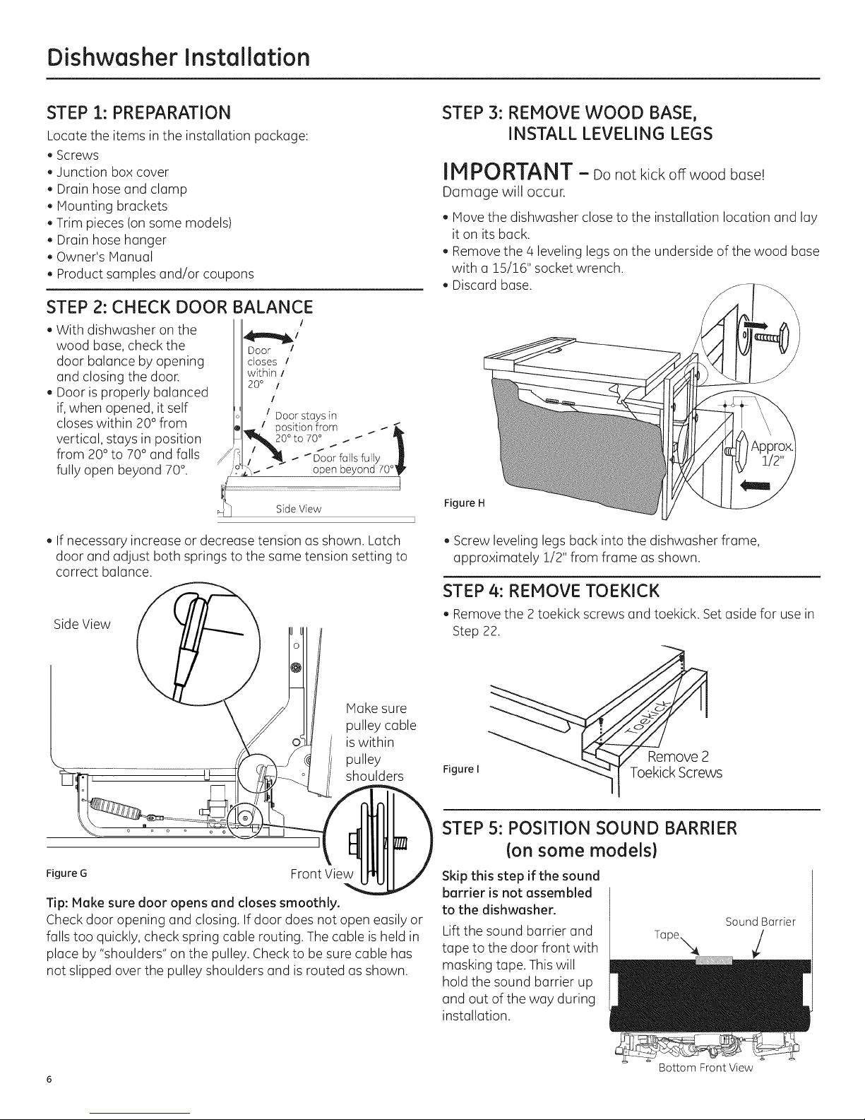
STEP 2: CHECK DOOR BALANCE
, With dishwasher on the
wood base, check the
door balance by opening
and closing the door.
, Door isproperly balanced
if, when opened, it self
closes within 20°from
vertical, stays in position
from 20°to 70° and falls
fully open beyond 70°.
Door _
closes /
within /
20 ° /
/
/ Door stays in
Position from _- _ _IL
20°to 70_ . -- -- "_
STEP 3: REMOVE WOOD BASE,
INSTALL LEVELING LEGS
IMPORTANT - Do not kickoffwood bose!
Damage willoccur.
, Move the dishwasher close to the installation location and lay
it on its back.
, Remove the 4 leveling legs on the underside of the wood base
with a !5/16" socket wrench.
, Discard base.
/
_Door falls fully ._
open beyond 70°_
Figure H
, If necessary increase or decrease tension as shown. Latch
door and adjust both springs to the same tension setting to
correct balance.
Side View
Make sure
pulley cable
iswithin
pulley
shoulders
Figure G Front View
Tip: Make sure door opens and closes smoothly.
Check door opening and closing. If door does not open easily or
falls too quickly, check spring cable routing. The cable is held in
place by "shoulders" on the pulley. Check to be sure cable has
not slipped over the pulley shoulders and isrouted as shown.
, Screw leveling legs back into the dishwasher frame,
approximately 1/2" from frame as shown.
STEP 4: REMOVE TOEKICK
, Remove the 2 toekick screws and toekick. Set aside for use in
Step 22.
Remove 2
FigureI Toekick Screws
STEP 5: POSITION SOUND BARRIER
Ion some models}
Skip this step if the sound
barrier is not assembled
to the dishwasher.
Lift the sound barrier and
tape to the door front with
masking tape. This will
hold the sound barrier up
and out of the way during
installation.
Sound Barrier
6
Bottom Front View
Page 7
Dishwasher Installation
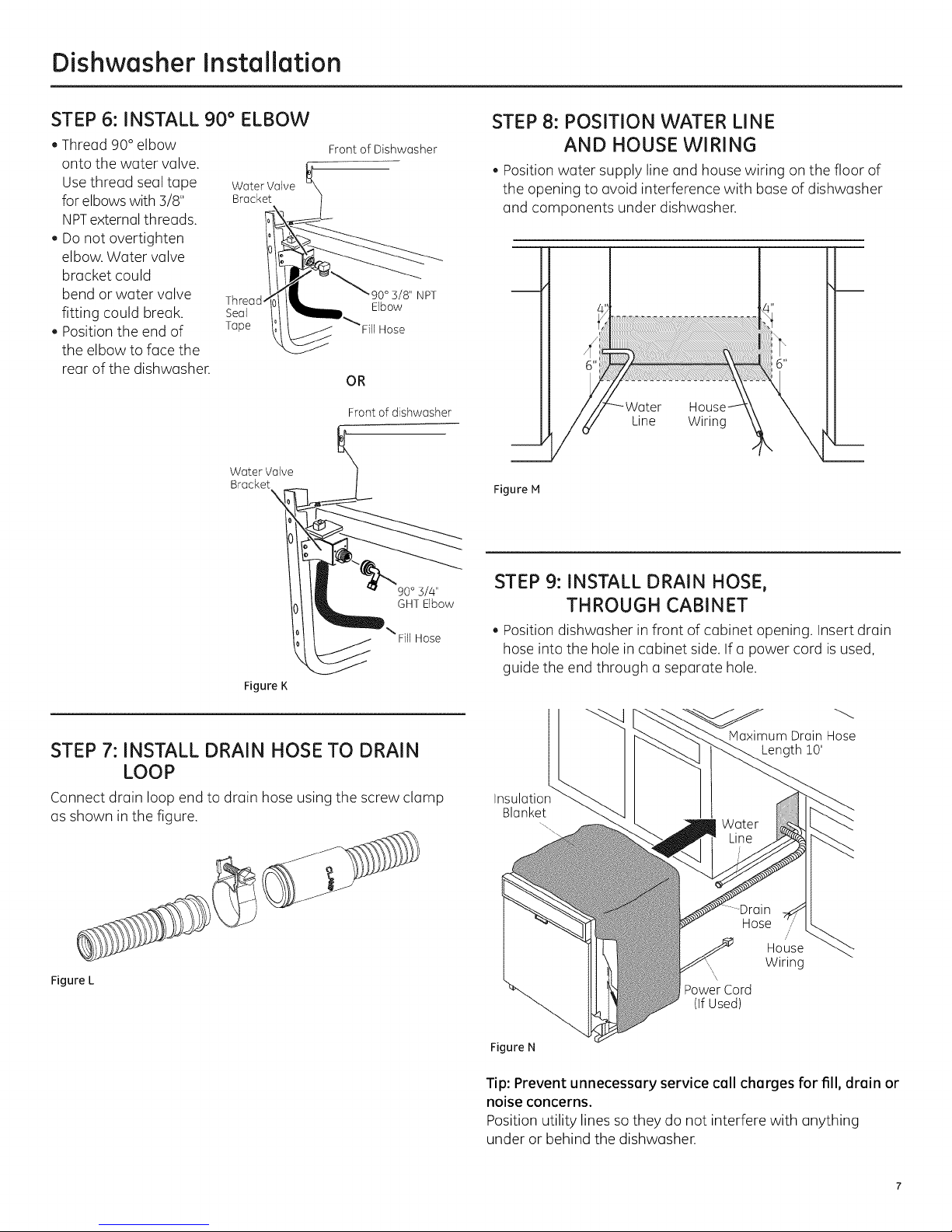
STEP 6: INSTALL 90 ° ELBOW
, Thread 90° elbow
onto the water valve.
Use thread seal tape Water Valve
for elbows with 3/8" Bracket
NPTexternal threads.
, Do not overtighten
elbow. Water valve
bracket could
bend or water valve Thread
fitting could break. Seal
, Position the end of Tape
the elbow to face the
rear of the dishwasher.
Water Valve
Bracket
\
Front of Dishwasher
NPT
Elbow
Fill Hose
OR
Frontof dishwasher
STEP 8: POSITION WATER LINE
AND HOUSE WIRING
, Position water supply line and house wiring on the floor of
the opening to avoid interference with base of dishwasher
and components under dishwasher.
Line Wiring
Figure M
\ Fill Hose
Figure K
STEP 7: INSTALL DRAIN HOSE TO DRAIN
LOOP
Connect drain loop end to drain hose using the screw clamp
as shown in the figure.
Figure L
STEP 9: INSTALL DRAIN HOSE,
THROUGH CABINET
, Position dishwasher in front of cabinet opening. Insert drain
hose into the hole in cabinet side. If a power cord is used,
guide the end through a separate hole.
Maximum Drain Hose
Length 10'
Blanket
Hose
//
House
, Wiring
\
PowerCord
(IfUsed)
Figure N
Tip: Prevent unnecessary service call charges for fill, drain or
noise concerns.
Position utility lines sothey do not interfere with anything
under or behind the dishwasher.
Page 8
Dishwasher Installation
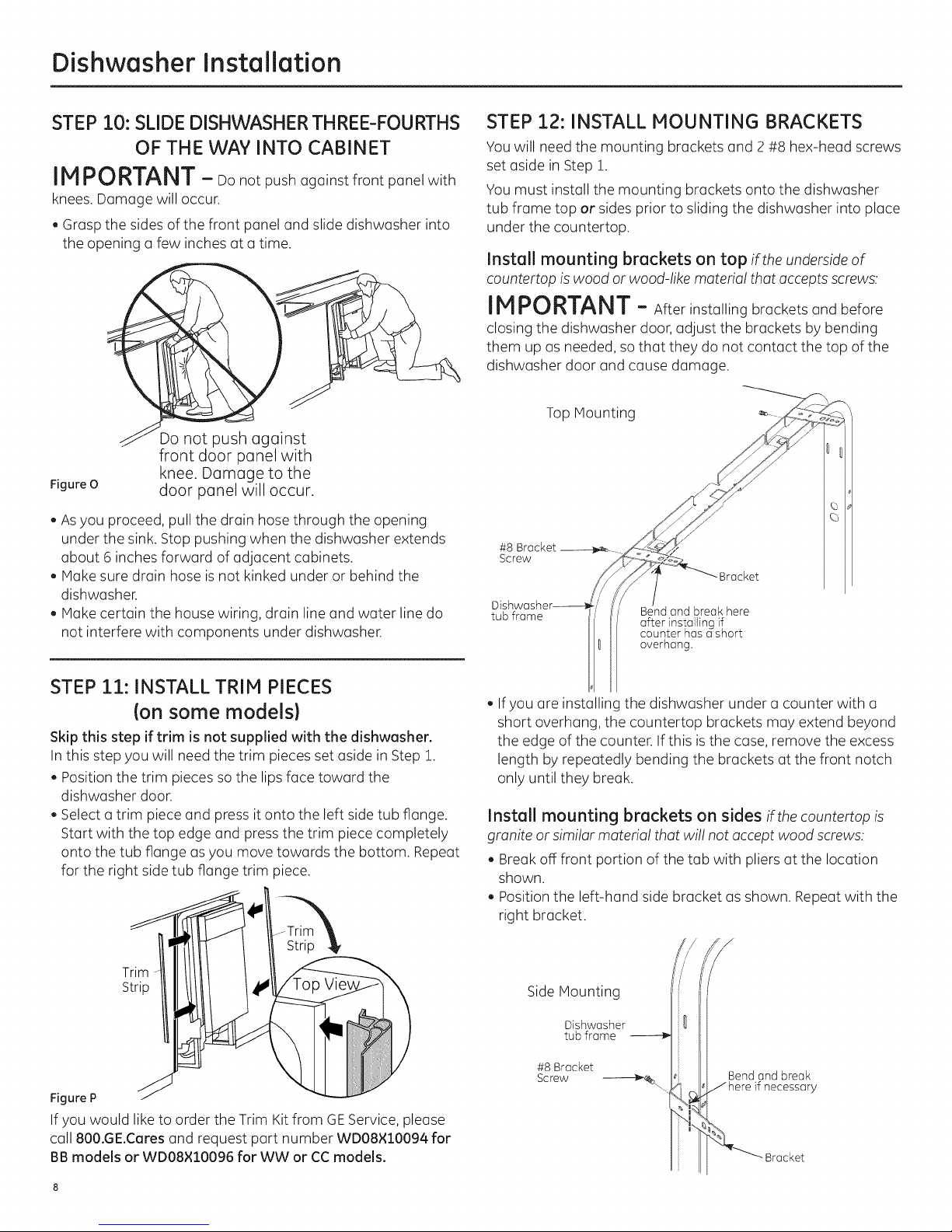
STEP 10: SLIDE DISHWASHER THREE-FOURTHS
OF THE WAY INTO CABINET
IMPORTANT- oonotpushagainstfrontpanelwith
knees. Damage will occur.
, Grasp the sides of the front panel and slide dishwasher into
the opening a few inches at a time.
Do not push against
front door panel with
Figure O
. As you proceed, pull the drain hose through the opening
under the sink. Stop pushing when the dishwasher extends
about 6 inches forward of adjacent cabinets.
. Make sure drain hose is not kinked under or behind the
dishwasher.
. Make certain the house wiring, drain line and water line do
not interfere with components under dishwasher.
knee. Damage to the
door panel will occur.
STEP 12: INSTALL MOUNTING BRACKETS
You will need the mounting brackets and 2 #8 hex-head screws
set aside inStep 1.
You must install the mounting brackets onto the dishwasher
tub frame top or sides prior to sliding the dishwasher into place
under the countertop.
Install mounting brackets on top if the underside of
countertop is wood or wood-like material that accepts screws:
IMPORTANT - Afterinstalling bracketsandbefore
closing the dishwasher door, adjust the brackets by bending
them up as needed, so that they do not contact the top of the
dishwasher door and cause damage.
Top Mounting
#8 Bracket
Screw
Bracket
DL_
tub frame Bend and break here
after installing if
counter has ashort
overhang.
STEP 11: INSTALL TRIM PIECES
{on some models)
Skip this step if trim is not supplied with the dishwasher.
Inthis step you will need the trim pieces set aside in Step 1.
. Position the trim pieces so the lips face toward the
dishwasher door.
. Select a trim piece and press it onto the left side tub flange.
Start with the top edge and press the trim piece completely
onto the tub flange as you move towards the bottom. Repeat
for the right side tub flange trim piece.
Figure P
If you would like to order the Trim Kitfrom GEService, please
call 800.GE.Cares and request part number WD08×10094 for
BB models or WD08×10096 for WW or CCmodels.
, If you are installinc the dishwasher under a counter with a
short overhang, the countertop brackets may extend beyond
the edge of the counter. If this is the case, remove the excess
length by repeatedly bending the brackets at the front notch
only until they break.
Install mounting brackets on sides if the countertop is
granite or similar material that will not accept wood screws:
. Break off front portion of the tab with pliers at the location
shown.
. Position the left-hand side bracket as shown. Repeat with the
right bracket.
Side Mounting
Dishwasher
tub frame
#8 Bracket
Screw --_%.
Bend and break
Jhere if necessary
Bracket
Page 9
Dishwasher Installation
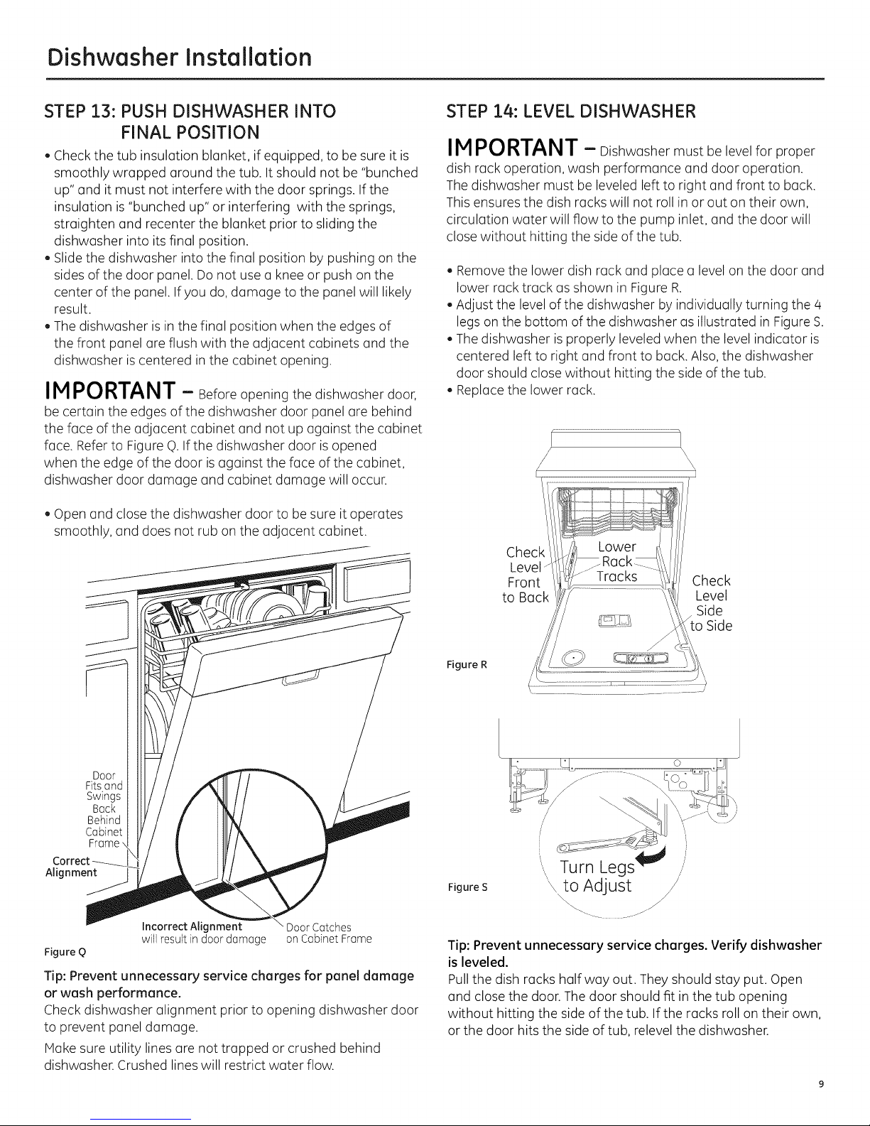
STEP 13: PUSH DISHWASHER INTO
FINAL POSITION
, Check the tub insulation blanket, if equipped, to be sure it is
smoothly wrapped around the tub. It should not be "bunched
up" and it must not interfere with the door springs. If the
insulation is"bunched up" or interfering with the springs,
straighten and recenter the blanket prior to sliding the
dishwasher into its final position.
. Slide the dishwasher into the final position by pushing on the
sides of the door panel. Do not use a knee or push on the
center of the panel. If you do, damage to the panel will likely
result.
The dishwasher isin the final position when the edges of
the front panel are flush with the adjacent cabinets and the
dishwasher is centered in the cabinet opening.
IMPORTANT - Before opening the dishwasher door,
be certain the edges of the dishwasher door panel are behind
the face of the adjacent cabinet and not up against the cabinet
face. Refer to Figure q).If the dishwasher door isopened
when the edge of the door isagainst the face of the cabinet,
dishwasher door damage and cabinet damage will occur.
, Open and close the dishwasher door to be sure it operates
smoothly, and does not rub on the adjacent cabinet.
STEP 14: LEVEL DISHWASHER
IMPORTANT - Dishwasher must be level for proper
dish rack operation, wash performance and door operation.
Thedishwasher must be leveled left to right and front to back.
This ensures the dish racks will not roll in or out on their own,
circulation water will flow to the pump inlet, and the door will
close without hitting the side of the tub.
, Remove the lower dish rack and place a level on the door and
lower rack track as shown in Figure R.
Adjust the level of the dishwasher by individually turning the 4
legs on the bottom of the dishwasher as illustrated in Figure S.
Thedishwasher isproperly leveled when the level indicator is
centered left to right and front to back. Also, the dishwasher
door should close without hitting the side of the tub.
Replace the lower rack.
_\\\\
Check
Level"
Front
to Buck
Check
Level
Side
to Side
Door
Fits and
Swings
Back
Behind
Cabinet
Frame
Alignment
Incorrect Alignment DoorCatches
Figure Q
will resultindoor damage on CabinetFrame
Tip: Prevent unnecessary service charges for panel damage
or wash performance.
Check dishwasher alignment prior to opening dishwasher door
to prevent panel damage.
Hake sure utility lines are not trapped or crushed behind
dishwasher. Crushed lines will restrict water flow.
Figure R
Figure S
'\to Adjust /
Tip: Prevent unnecessary service charges. Verify dishwasher
is leveled.
Pull the dish racks half way out. They should stay put. Open
and close the door.The door should fit in the tub opening
without hitting the side of the tub. If the racks roll on their own,
or the door hits the side of tub, relevel the dishwasher.
Page 10
Dishwasher Installation
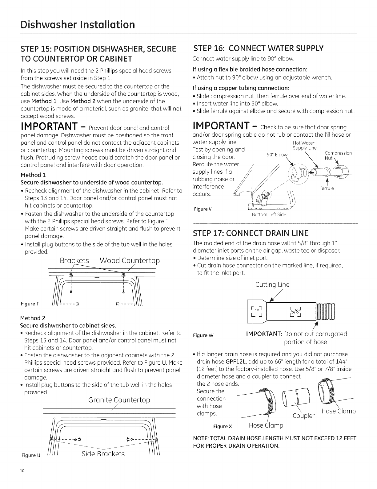
STEP 15: POSITION DISHWASHER, SECURE
TO COUNTERTOP OR CABINET
Inthis step you will need the 2 Phillipsspecial head screws
from the screws set aside in Step 1.
The dishwasher must be secured to the countertop or the
cabinet sides. When the underside of the countertop is wood,
use Method 1. UseMethod 2when the underside of the
countertop is made of a material, such as granite, that will not
accept wood screws.
IMPORTANT - Preventdoorpaneland control
panel damage. Dishwasher must be positioned so the front
panel and control panel do not contact the adjacent cabinets
or countertop. Mounting screws must be driven straight and
flush. Protruding screw heads could scratch the door panel or
control panel and interfere with door operation.
Method 1
Secure dishwasher to underside of wood countertop.
. Recheck alignment of the dishwasher in the cabinet. Referto
Steps 13 and 1/4.Door panel and/or control panel must not
hit cabinets or countertop.
. Fasten the dishwasher to the underside of the countertop
with the 2 Phillips special head screws. Refer to Figure T.
Make certain screws are driven straight and flush to prevent
panel damage.
• Install plug buttons to the side of the tub well inthe holes
provided.
Brackets Wood Countertop
STEP 16: CONNECT WATER SUPPLY
Connect water supply line to 90° elbow.
If using a flexible braided hose connection:
Attach nut to 90° elbow using an adjustable wrench.
If using a copper tubing connection:
Slide compression nut, then ferrule over end of water line.
Insert water line into 90° elbow.
Slide ferrule against elbow and secure with compression nut.
IMPORTANT - Checktobesurethatdoorspring
and/ordoorspringcabledo notruborcontactthefillhoseor
water supply line.
Test by opening and
closing the door.
Reroute the water
supply lines if a
rubbing noise or
interference
occurs.
Figure V
90° Elbow \ Compression
Bottom Left Side
STEP 17: CONNECT DRAIN LINE
The molded end of the drain hose will fit 5/8" through 1"
diameter inlet ports on the air gap, waste tee or disposer.
Determine size of inlet port.
Cut drain hose connector on the marked line, if required,
to fit the inlet port.
Hot Water
Supply Line
\ \ Nut
Ferrule
Figure T
Method 2
Secure dishwasher to cabinet sides.
. Recheck alignment of the dishwasher in the cabinet. Refer to
Steps 13 and 1/4.Door panel and/or control panel must not
hit cabinets or countertop.
. Fasten the dishwasher to the adjacent cabinets with the 2
Phillips special head screws provided. Refer to Figure U. Make
certain screws are driven straight and flush to prevent panel
damage.
Install plug buttons to the side of the tub well inthe holes
provided.
Granite Countertop
Figure U
/
/
/
Cutting Line
/
#
Figure W
. If a longer drain hose is required and you did not purchase
drain hose GPF12L,add up to 66" length for o total of 14/4"
(12 feet) to the factory-installed hose. Use5/8" or 7/8" inside
diameter hose and a coupler to connect
the 2 hose ends.
connection
with hose
Secure the
clamps. Coupler
Figure × Hose Clamp
NOTE: TOTAL DRAIN HOSE LENGTH MUST NOT EXCEED 12 FEET
FOR PROPER DRAIN OPERATION.
IMPORTANT: Do not cut corrugated
portion of hose
Hose Clamp
lO
Page 11

Dishwasher Installation
STEP 17: CONNECT DRAIN LINE (Cont.)
. Connect drain line to air gap, waste tee or disposer
using the previously determined method. Secure hose
with a screw-type clamp.
Method 1 - Air gap with waste tee or disposer
Waste Tee Installation Disposer Installation
Figure Y
Method 2 - "High drain loop" with waste tee or disposer
With this method you will need the drain hose hanger set aside
in Step 1.
Fasten drain hose to underside of countertop with the provided
hanger.
__ Drain Hos,e Hanger
STEP 18: CONNECT POWER SUPPLY
Ifa power cord with plug is already installed proceed to
Step 19.
AWARNING:
If house wiring is not 2-wire with ground, a ground must be
provided by the installer. When house wiring is aluminum, be sure
to useUL-Listedanti-oxidantcompoundandaluminum-to-copper
connectors.
A ADVERTENCIA:
Sielcableadodom@sticonocuentaconuncablede2hiloscon
conexi6natierra,uninstaladordeberealizarunaconexi6na tierra.
Cuandoelcableadodom@sticoesdealuminio,asegOresedeusar
uncompuestoantioxidanteyconectoresdealuminioacobre
aprobadosparUL
In this step you will need the junction box cover and the
#10 Hex head screw from the screws set aside in Step 1.
. Secure house wiring to the back of the junction box with a
strain relief.
. Locate the 3 dishwasher wires, (white, black and green) with
the stripped ends coming out of the ACjumper. Use ULlisted
wire nuts of appropriate size to connect incoming ground to
green, white to white and black to black.
. Install the junction box cover using #10 hex head screw.
Check to be sure that wires are not pinched under the cover.
. Hake sure that the junction box cover is resting on the
mounting bracket.
WasteTeeInstallation
Figure Z
DisposerInstallation
IMPORTANT - When connecting drain line to
disposer, check to be sure that drain plug has been removed.
DISHWASHERWILL NOTDRAINIFPLUGISLEFTINPLACE.
Drain
Plug
4 Remove
Tip: Avoid unnecessary service call charges for a no drain
complaint.
Make sure excess drain hose has been pulled through
the cabinet opening. This will prevent excess hose in the
dishwasher cavity from becoming kinked or crushed by the
dishwasher.
NOTE:Do not remove the
Junction Box Bracket.
White
Figure AA
Black
Ground
AC
Ground
Screw
11
Page 12

Dishwasher Installation
STEP 19:PRETEST CHECKLIST
Reviewthislistafterinstallingyourdishwashertoavoid
chargesfora servicecallthatisnotcoveredbyyour
warranty.
,Check to be sure power is OFF.
,Open door and remove all foam and paper packaging.
,Locate the Owner's Manual set aside in Step 1.
,Read the Owner's Manual for operating instructions.
,Check door opening and closing. Ifdoor does not open and
close freely, check for proper routing of spring cable over
pulley. If door drops or closes when released, adjust spring
tension. See Step 2,
. Check to be sure that wiring is secure under the dishwasher,
not pinched or in contact with door springs or other
components. See Step 18.
, Check door alignment with tub. If door hits tub, level
dishwasher. SeeStep 1/4.
,Pull lower rack out, about halfway. Checkto besure it does
not roll back or forward on the door. If the rack moves, adjust
leveling legs. SeeStep 1/4.
,Check door alignment with cabinet. If door hits cabinet,
reposition dishwasher. See Step 13.
,Check that door spring does not contact water line,fill hose,
wiring or other components. See Step 15.
STEP 20: DISHWASHER WET TEST
,Turn on power supply or plug power cord into outlet,
if equipped.
, Select acycle to run and push the Start/Reset pad.
, Ensurethe door is latched. Dishwasher should start.
,Check to be sure that water enters the dishwasher. If water
does not enter the dishwasher, check to be sure that water
and power are turned on.
,Check for leaks under the dishwasher. If a leak isfound, turn
off power at the breaker, and then tighten water connections.
Restore power after leak is corrected.
,Check for leaks around the door.A leak around the door could
be caused by door rubbing or hitting against
adjacent cabinets. Reposition the dishwasher if necessary.
SeeStep 13.
Pressand hold the Start/Reset pad for 3 seconds to cancel
the cycle. The unit will begin to drain. Check drain lines. If
leaks are found, turn off power at the breaker and correct
plumbing as necessary. Restore power after corrections are
made. SeeSteps 7,9, 10 and 17.
,Open dishwasher door and make sure all of the water has
drained. If not, check that disposer plug has been removed
and/or air gap is not plugged. Also check drain hose to be
sure it is not kinked underneath or behind dishwasher. See
Step 17.
,Verify water supply and drain lines are not kinked or in
contact with other components. Contact with motor or
dishwasher frame could cause noise.
,Turn on the sink hot water faucet and verify water
temperature. Incoming water temperature must be between
120°Fand 140°F.A minimum of 120°F temperature is
required for best wash performance. See "Prepare Hot Water
Line,"page 5.
,Add 2 quarts of water to the bottom of the dishwasher to
lubricate the pump seal.
,Turn on water supply. Check for leaks. Tighten connections if
needed.
, Remove protective film if present from the control panel and
door.
PressStart/Reset pad once again and run dishwasher
through another cycle. Check for leaks and correct if
required.
Repeat this step as necessary.
12
Page 13

Dishwasher Installation
STEP 21: POSITION SOUND BARRIER
AND INSULATION
{on some models)
Skip this step if the sound barrier is not assembled to the
dishwasher.
. Locate the sound insulation package inside the dishwasher.
, Locate the control box.
Control
Box
, Peeloff the paper from the insulation.
, Apply the insulation to the underside of the control box and
flush with its front face as shown.
Insulation shown adhered to bottom edge of the control
box, flush with the front face, and correctly placed along
dishwasher bottom.
, Remove the masking tape from the sound barrier, and door
front. Re-position the sound barrier over the sound insulation.
Sound
STEP 22: REPLACE TOEKICK
. Place toekick against the legs of the dishwasher.
Screws
Figure CC
Align the toekick with the bottom edge and make sure it is
against the floor.
Insert and tighten the 2toekick attachment screws. The
toekick should stay in contact with the floor.
When reinstalling the toe kick on models with a sound barrier,
ensure that the bottom edge of the rubberized flap isflush
with the floor. Any excess material should be tucked up
behind the outer door. Donot allow excess rubberized flap to
lay on the floor. Ifany excess is not tucked completely behind
the outer door, it will bunch up between the door and toe kick
and impede proper opening and closing of the door. Thiswill
be noticeable because the door will not stay fully open and
will spring up.
Tip: Reduce sound from under the dishwasher.
Hake sure toekick is against floor.
STEP 23: LITERATURE
, Besure to leave complete literature package, these
Installation Instructions and product samples and/or coupons
with the consumer.
L
Burrier
13
Page 14

Notes
14
Page 15

Notes
15
Page 16

SPECIFICATIONS SUBJECT TO CHANGE WITHOUT NOTICE
GEAppliances
General Electric Company
Louisville, Kentucky/40225
GEAppliances.com
© 2013 General Electric Company
Page 17

Appareils m@nagers
Directivesd'instailation
Lave-vaisselleencastr@
Pourtoute question, composez le 1.800.561.3344 ou visitez notre site Web:
www.electromenagersge.ca
AVANT DE COMMENCER
Veuillez lira attentivement toutes lesdirectives
qui suivent.
IMPORTANT - Observeztouslescodeset
ordonnances en vigueur.
. Note 6 I'instellateur - Veuillez laisser les pr6sentes directives
au consommateur pour I'inspecteur local.
. Note au consommateur - Veuillez conserver les pr6sentes
directives avec votre Manuel d'utilisation pour consultation
ult6rieure.
. Comp_tences requises - L'installation de ce lave-vaisselle
exige des comp6tences de base en m6canique, en 61ectricit_
et en plomberie. L'installateur est responsable de la qualit_
de I'instellation. Toute d@failJancedu produit ettribuable
6 une installation ined@uate n'est pus couverte par la
garantie de GE. Reportez-vous a la garantie du produit.
. Dur@ede I'installation - Entre 1 et 3 heures. L'installation
d'un nouveau lave-vaisselle exige plus de temps qua
le remplacement d'un ancien mo@le.
VEUILLEZ LIRE ATTENTIVEMENT
ET CONSERVER CES DIRECTIVES.
IMPORTANT - Le lave-vaisselle DOIT_tre install6 de
mani_re 6 ce qu'il puisse _tre sorti de son emplacement si des
r@arations sont n6cessaires.
II importe d'user de prudence Iorsque I'appareil est install6
ou d@lac6 afin de pr6venir I'endommagement du cordon
d'alimentation.
Si lelave-vaisselle que vous avez request endommag6,
communiquez imm6diatement avec votre d6taillant ou
I'entrepreneur en construction.
Accessoires facultatifs - Reportez-vous au Hanuel d'utilisation
pour conndtre les ensembles pour panneau d6coratif
personnalis6 offerts.
POURVOTRES CUR T
Veuillez lira et observer toutes les raises en garde
(ATTENTION et AVERTISSEMENT} donn_es dens les pr_sentes
directives. Pour effectuer I'instellation d_crite dans les
pr_sentes directives, il faut porter des gents et des lunettes
de s_curit_.
Imprimd auxEtats-Unis 31-31506-3 04-13 GE
Page 18

Pr6paration pour I'installation
PIt CESFOURNIES DANS UEMBALLAGE:
, Couverclede la bottedejonction etvis 6t6te
hexagonalen° 10
, Collier
, Boyaudevidange (198cm/78 po de long)
, Supportde twau devidange)
, 2vis(3t6te hexagonaleno 8-18pourfixer lessupports
au cadre delacuvedulave-vaisselle
, 2 Boutonsdebouchon
, 2 Moulureslat6rales(certainsmod61es)
, 2supportsdemontage pour comptoirsou armoires
lat6ralesen bois
, 2vis(3t6te sp6cialePhillipsn°8-18 x !5,8 mm
(5/8po)pourfixerlelave-vaisselleau dessous
du comptoir ouarmoireslat6rales
, Documentation,#chantillonset(ou)bans
MATI RIEL NI CESSAIRE:
, Coudede90°,bagueet#crou (_compression(filetageexterneNPT
de 9,5mm (3/8po)ou 19,! mm [5/4po]filet pour tuyaud'arrosage
dejardin pourlave-vaisselle5 uneextr#mit#et I'autreextr#mit#
conquepour leraccordement5 laconduited'alimentationeneau)
, Rubanpourjoints filet#s
, Connecteursvissableshomologu#sUL(3)
, Ruban-cache
Pour une nouvelle installation: (s'il y a lieu)
, Coupureanti-refoulementpour leboyaudevidange,sin#cessaire
, RaccordenT pour la plomberiede la r#sidence,s'ily a lieu
, C_ble#lectriqueoucordon d'alimentation
, Colliers5 vissansfin
, Bagueanti-traction pour leraccordement 61ectrique
, Robinetd'arr6t(recommand6)
, Conduited'alimentationeneau - twau en cuivred'aumains
9,5mm (5/8po)ou un boyauflexibletress6noW×18×326de GE
, BoyaudevidangeGPF12L(5.66m/!2 pidelong),sin6cessaire
\
Couvercle de la
boTte de jonction
et vis 6 t_te
hexogonole n°10
Support de tuyou
de vidange
Ruban-cache
?
Vis 6 t_te
hexagonale n° 10
de 12,7 mm {1/2 po)
de long pour boTte
dejonction
(sur certoins modules)
Coude de 90 °,
bogue et _crou
a compression
?
Roccord en T
Colliers avis sans fin
Coupure
onti-refoulement
Collier
??
Vis 6 t@te hexagonole
n° 8 pour support de
montage
Supports de
montage
©
Robinet
d'orr_t
CSble _lectrique (ou cordon
d'alimentation, s'il y a lieu)
Bogue anti-traction
Rubon pour
joints filet_s
(sill y a lieu)
Boyaudevidange
n
Boutons de
bouchon
Visa t_te
sp_ciole
Phillips n°8
de 15,8 mm
(5/8 po) de long
Connecteurs
vissables {3)
Conduited'eou
chaude
Boyau de vidange
facultotif GPF12L
de 3.66 m (12 pi)
OUTILS NI CESSAIRES:
, TournevisPhillips
, Tourne-6crousde6,3 mm(1/4 po)et
de 7,9mm(5/16 po)
, CI65 molette de15,2cm(6po)
, Niveau
, Equerrede charpentier
, Ruban5 mesurer
, Lunettesdes_curit#
, Lampedepoche
, Seaupour recueillirI'eauIorsdu rinqage
de laconduited'eau
, CI_5 douillede 23,8mm (15/16po)
(facultatif- pour enleverlabasedebois)
, Gants
, Pince
, Pour une nouvelle installation:
, Coupe-tubes
, Perceuseetforetsappropri#s
, Jeu descies-cloche
Phillips
CI_ 6 douille de
23,8 mm (15116 po)
Lampe de poche
Gants
Tou
de 6,3 mm 11/4 po)
et de 7,9 mm (5/16 po)
Pince
CI6 6 molette
de 15,2 cm
(6 po)
Seou
Niveou
I_querre de
charpentier
Coupe-tubes
Ruban 6 mesurer
Page 19

Preparation pour I'installation
PRI_PARATION DE L'OUVERTURE DANS
LESARMOIRES
Lemur du fond
doit _tre exempt
de tuyaux ou
de ills
33-1/2 po to 34-3/4 po
du dessous du
comptoir au
plancher
Armoires (3
1'6querre et
_d'aplomb
Figure A
61,0 cm
(24 po) min.
. L'ouverture dons les armoires doit mesurer au moins
61,0 cm (24 po)de largeur et de profondeur, et environ
87,6 cm (34-!/2 po) de hauteur 6 partir du plancher
jusqu'au-dessous du comptoir.
AVERTISSEMENT:
Pourr_duirelesrisquesdechoc_lectrique,d'incendieou de
blessures,I'installateurdoits'assurerque lelave-vaisselleest
compl_tementencastr_au momentdeI'installation.
Lelave-vaisselle doit _tre install6 de faqon 6 ce que le boyau
de vidange mesure au maximum 3.66 m_tres (12 pieds) pour
assurer une vidange ad6quate.
Ledessus, lesc6t6s et I'arri_re du lave-vaisselle doivent
_tre compl_tement dissimul6s 6 I'int@ieur de I'ouverture.
Lelave-vaisselle nedoit soutenir aucune pattie de la
structure des armoires.
DI_GAGEMENTS:
. Dans le cos d'une
installation duns un
coin, veuillez pr@oir un
d6gagement d'au moins
5,1 cm (2po) entre le Iove-
vaisselle et lesarmoires, le
mur ou un 61ectrom6nager
adjacent. Veuillez pr6voir
un d6gagement d'au moins
72 cm (28-3/8 po)a I'avant
du lave-vaisselle pour
I'ouverture de la porte.
Reportez-vous (_la Figure B.-
. Laisserunespaced'au moins -
!5,2 cm (6po)entreleIove-
vaisselle,la cuisini@eou autres
appareilsavecfour.
Comptoir
72#1283,8pol
7/ S,1 cm(2 po) minimum pourI'ouverture de la porte
Figure B
EXIGENCES RELATIVES AU SYSTEME
DE VIDANGE
. Veuillezobserverlesordonnonces et lescodesIocauxen vigueur.
. Leboyau de vidange doitavoir une Iongueur maximale de
3.66m_tres (!2 pieds).
REHARQUE:IIfaut installerune coupure anti-refoulement si le
raccord au broyeura d6chetsou au raccord enTsetrouve a moins
de 46 cm (18po)au-dessusduplancher (]fin d'@iter un siphonage.
CHOI× DE LA MI_THODE DE VIDANGE
Letype d'installation de vidange d6pend des conditions suivantes.
. Lesordonnancesou codesIocauxen vigueurexigent-ils
une coupure anti-refoulement?
. Leraccorclen Tsetrouve-t-il (_moinsde 46cm (18po)
du plancher?
Sivous r6pondez OUl 6 I'une ou I'autre de ces questions,
vous DEVEZutiliser la m_thode n° 1.
. Sivous r_pondez NON,vouspouvezemployer I'uneou I'autre
desm@hodes.
PR(=PARATION DES ARMOIRES
. Percezun trou de 3,8cm (1-1/2 po)dediam_tre densk] paroi de
I'armoirequi setrouve dans la partie ombr6e de I(] FigureApour
leboyau devidange.Assurez-vousque I'orificenepr6sente pas
d'ar@esvives.
Figure C
H_thode n° 1 - Coupure anti-refoutement avec raccord en T ou
broyeur 6 d_chets
IIfaut installer une coupure anti-refoulement Iorsqu'elle est exig_e par
les ordonnances et les codes Iocaux en vigueur. Cette coupure anti-
refoulement doit _tre install_e conform_ment aux directives donn_es
par le fabricant.
Crochet pour boyau de vidange j,M9 Crochet pour boyau t vidange
Iql / (C_l I82cm F
/ pl III [ _llS2; _°1/
m,n. IIII .V cd.?t /
118po)min _ (18po)_ L
Figure D
IMPORTANT - Lorsquevous
bronchezleboyoudevidongea un
broyeur(_d6chets,ossurez-vousd'enlever
lebouchondevidonge.LELAVE-VAISSELLE
NE POURRA PASSEVIDER SI VOUS LAISSEZLEBOUCHON EN PLACE,
bouchon
de vidange
4 nlevezle
M@thode n° 2 - Boucle de vidange @lev@eavec raccord en T ou
broyeur a d@chets
Conseil: Pour @viter des frois de r(_poration inutiles.
Assurez-vous d'enlever le bouchon de vidange du broyeur a
d6chets ovont d'y broncher le boyou de vidonge du Iove-voisselle.
3
Page 20

Preparation pour I'installation
PRE PARATION DU C#,BLAGE E LECTRIOUE
AVERTISSEMENT:
POURVOTRESECURITEPERSONNELLE:Enlevezlefusibleou
d@clenchezledisjoncteurau panneaudedistributionprincipal
avant de commencerI'installation.N'utilisezpasune rallonge
@lectriqueou un adaptateurdefiche aveccetappareil.
Alimentotion @lectrique
.Cet appareil doit _tre aliment6 par un courant de 120 Vet
60 Hz,et branch6 6 un circuit individuel correctement mis
6 laterre et prot6g_ par un disjoncteur de !5 ou 20 amperes
ou un fusible temporis6.
. Le c@ble61ectriquedoit poss6der deux fils, plus un fil de mise
6 laterre, et r6sister 6 une temp6rature nominale de 75 °C
(176 °F).
. Sivotre alimentation 61ectrique ne r6pond pas 6 ces
exigences, appelez un 61ectricien agr66 avant de poursuivre
I'installation.
Mise 6 la terre- Branchement permanent
Cet appareil doit _tre branch6 6 un r6seau _lectrique
permanent mis 6 la terre. Sinon, il faut installer un conducteur
de raise 6 la terre avecles conducteurs du circuit et le brancher
6 la borne de raise 6 la terre du r6seau ou au fil de raise 6 la
terre de I'appareil.
Mise 6 la terre - ModUles dot_s d'un cordon d'alimentotion
Cet appareil doit _tre mis 6 la terre. Encas de mauvais
fonctionnement ou de d6faillance, la raise6 la terre r6duira
les risques de choc 61ectrique en fournissant au courant
61ectrique un circuit de moindre r6sistance. Cet appareil est
dot6 d'un cordon d'alimentation poss_dant un conducteur
de raise 6 laterre et une fiche de raise 6 la terre. Lafiche
doit _tre branch6e clans une raise appropri6e, install6e et
raise 6 laterre en conformit6 avec tousles codes Iocaux et
ordonnances en vigueur.
A AVERTISSEMENT:
Un branchement inad_quat du conducteur de raise 6 la terre
peutpr@senterdes risquesdechoc @lectrique.Sivousn'@tespas
certain que I'appareilestcorrectementmis6 laterre,consultez
unr@parateurou un @lectricienqualifi@.
_'/ /_- Autreemplacement _'\
46 cm (18 po)
-- 46 cm i÷ la prise d_--_l
(18po) I c°urclr"tIS1
/ _ possiblepourla l \
_ i prisede courant i \I \
"Trou de 3,8 cm
/1÷'-
15cm 16po) 15 cm-_
Mise 6 la terre
Figure E Blanc
Dons le cos des modules dot_s d'un cordon d'alimentotion:
Ne modifiez pas la fiche fournie avec I'appareil; si vous ne
pouvez pas la brancher dans la prise de courant, faites installer
une prise de courant appropri6e par un technicien qualifi6.
Preparation des ormoires et cheminement des ills
. Les fils peuvent entrer dans I'ouverture du c6t_ droit, du c6t_
gauche, de I'arri_re ou du plancher dans la pattie ombr6e de
la Figure Eet de la FigureA.
. Percez un trou de 3,8 cm (1-!/2 po) de diam_tre au maximum
pour le passage du cable 61ectrique.Le bard du trou doit
_tre lisse et arrondi. Les fils 61ectriques pour le branchement
permanent peuvent passer par le m_me trou que le boyau
de vidange et la conduite d'eau chaude, si c'est plus pratique.
Si letrou est pratiqu6 dans une paroi en m6tal, les bards de
I'orifice doivent _tre recouverts d'un passe-fils pour prot6ger
les fils.
REMARQUE:Lecordon d'alimentation dot6 d'une fiche doit
passer par un autre trou.
Branchement _lectrique du lave-voisselle
Le branchement _lectrique s'effectue du c6t_ avant droit du
lave-vaisselle.
Dans lecas d'un branchement permanent, le c_ble doit _tre
achemin_ de la faqon indiqu_e 6 la Figure E.Lec_ble doit
avoir une Iongueur minimale de 61 cm (24 po) 6 partir du tour
arri_re.
Dans lecas d'un branchement avec un cordon d'alimentation,
installez une prise de courant raise 6 la terre 6 trois broches
sur la paroi de I'armoire adjacente, entre 15cm (6 po) et
46 cm (18 po) de I'ouverture, et entre 15 cm (6 po) et 46 cm
(18 po)du plancher.
Utilisez WD06×10020 Trousse de cordon d'alimentation pour
lave-vaisselle.
7,6cm (3po)
des armoires
Noir
Page 21

Preparation pour I'installation
PRI PARATION DE L'ALIMENTATION EN
EAU CHAUDE
REMARQUE:GErecommande I'utilisation d'un tuyau en cuivre
pour la conduite d'alimentation en eau, mais vous pouvez choi-
sir un boyau flexible tress# no W×28×326 de GE.
, La conduite d'alimentation en eau (tuyau de cuivre de 9,5 mm
[3/8 po] ou boyau flexible tress#) peut entrer du c6t# gauche,
du c6t_ droit, de I'arri_re ou du pluncher dans la partie
ombr#e indiqu#e dans la Figure F.
, La conduite d'alimentation en eau doit passer dans le m_me
trou que le cable 61ectrique et le boyau de vidange. Ou vous
pouvez percer un trou suppl#mentaire de 3,8 cm (1-1/2 po) de
diam_tre pour le passage de la conduite d'eau. Si I'appareil
est dot# d'un cordon d'alimentation pourvu d'une fiche, la
conduite d'eau chaude ne doit pas passer par le m_me trou
que le cordon d'alimentation.
Raccordement de la conduite d'eau chaude
, Sivous utilisez un boyau flexible tress_, @iquetez le boyau
et indiquez la date d'installation 6 des fins de r#f@ence. Les
boyaux fiexibles tress#s doivent _tre remplac#s dens 5 ans.
, Coupez I'alimentation en eau.
, Installez un robinet d'arr_t 6 un endroit accessible, par
exemple sous I'#vier.(Cette installation est facultative,
mais fortement recommand#e, et peut m_me _tre exig#e
par lescodes Iocaux en vigueur.)
, Le raccordement de la conduite d'eau s'effectue du c6t#
gauche du lave-vaisselle. Installez la conduite d'eau chaude
en utilisant un tuyau en cuivre de 9,5 mm (3/8 po) ou plus ou
un boyau flexible tress#. Acheminez la conduite d'eau de la
faqon indiqu#e dens la Figure Fet amenez-la vers I'avant 6
au moins 48,2 cm (19 po) dumur arri@e.
, R#glez le chauffe-eau 6 une temp@ature variant entre 49 °C
(120 °F)et 65 °C(140°F).
, Rincez laconduite d'eau pour _liminer tousles d#bris.
Recueillez I'eau et lesd#bris 6 I'aide d'un seau.
, La pression de la conduite d'alimentation en eau chaude doit
verier entre 1,4 bar (20Ib/po 2)et 8,3 bars (120 Ib/po2).
Tournez la page pour commencer
I'installation du lave-vaisselle.
ii Robinet dedk].
Eau _ d'arr@
chaude _...........
(2po)de
I'ormoire
Devant des
armoires
Figure F
Trou de
3,8cm
A ATTENTION:
N'enlevezpaslabasedeboisavantd'etre pr_t6 installerle lave-
vaisselle.Sivousenlevezla basedebois,le lave-vaissellepourrait
basculerIorsquevousouvrezla porte.
48,2 cm (19 po)
5,1cm (2po)
du plancher
Page 22

Installation du lave-vaisselle
I_TAPEi: PRI_PARATION
Prenezles pisces fournies dans I'emballage et mettez-les de c8t6:
, Ensemble de vis
, Couvercle de la boTtedejonction
, Boyau de vidange et collier
, Supports de montage
, Moulures (certains mod61es/
, Crochet pour boyau de vidange
, Manuel d'utilisation
, Echantillons et(out bons
I_TAPE 2: VITRIFICATION DE L'F'-QUILIBRE
DE LA PORTE
, Sans enlever labase de
bois du lave-vaisselle,
v6rifiez 1'6quilibrede la
porte en I'ouvrant et en la
fermant.
. La porte est correctement
6quilibr6e si, 6tant ouverte,
elle se referme d'elle-
m#me a I'int@ieur de 20°
de la verticale, reste en
position de 20°6 70°,et
s'ouvre enti@ement au-
del6 de 70°.
. Au besoin, augmentez ou diminuez la tension de la faqon
indiqu6e dans I'illustration. Verrouillez la porte et r6glez
les ressorts de mani_re 6 obtenir un 6quilibre appropri6.
Vue lat6rale
L9 porte se !
reTerme /
&Pint6rieur
de 20° /
/
/
/ La porte reste
_,_ / en position de ..- _.
/J / _ _ _ _ La porte_
y , _ / _s'ouvre enti@ement
S.._ ..a..u_.:del6de 70° _"
_L] Vue lat6rale
20°(370 ° _ _
S'assurer
que le c_ble
de poulie
se trouve
entre les
6paulements
de la poulie
I_TAPE 3: ENLI_VEMENT DE LA BASE DE BOIS,
INSTALLATION DES PIEDS
DE NIVELLEMENT
IMPORTANT - Ne frappez pas sur la base
de bois pour l'enlever! Vous endommagerez ainsi
l'appareil.
,Amenez le lave-vaisselle 6 proximit6 de son emplacement
d6finitif et couchez-le sur le dos.
, Enlevez les quatre pieds de nivellement sous la base de bois
6 I'aide d'une cl6 6 douille de 23,8cm (15/!6 po).
. Enlevez etjetez la base de bois.
1,27 cm (1/2
po) approx
Figure H
Remettez en place les pieds de nivellement sur le lave-
vaisselle, 6 1,27cm (1/2 po) environ du cadre, comme indiqu6
dans I'illustration.
I_TAPE4: ENLI_VEMENT DU PANNEAU
INFI_RIEUR
. Enlevezles deux vis du panneau inf@ieur,ainsi que le
panneau inf@ieur. Mettez-les de c6t6 pour les r6utiliser
6 I'@ape 22.
Vue avant
Figure G
Conseil: Pour que la porte ouvre et se ferme facilemento
V@ifiez la porte en I'ouvrant et en la fermant. Sielle n'ouvre
pas facilement ou s'ouvre trop rapidement, v@ifiez la
disposition du cSble du ressort. LecSble est retenu en place
par des <<6paulements>>sur la poulie. Assurez-vous que le
cSble est bien install6 sur les 6paulements de la poulie comme
indiqu&
Figure I
Enlevezlesdeu×
visdu panneau
inf@ieur
Page 23

Installation du lave-vaisselle
I_TAPE5: INSTALLATION DU MATI_RIAU
INSONORISANT (sur certaJns modules)
Passez6 l'@tapesuJvant
si le lave-vaisselle n'est
pas @quip_de mat_riau
insonorisant
iVlatariau
insonorisant
Relevezle mat#riau
insonorisant et le ruban et
fixez-le au panneau frontal
6 I'aide du ruban-cache.
Ceci permettra de garder
le mat@iau insonorisant
relev6 et de dagager la
zone de travail pendant
I'installation.
Vue avant du uanneau inf@ieur
I_TAPE6: INSTALLATION
DU COUDE DE 90 °
, Vissezle coude de 90° dans
1'61ectrovanne.Utilisez du
ruban pour joints filet@s
sur les coudes 6 filetage
ext@ieur 3/8 po NPT.
, Neserrezpaslecoudede
faqon excessive;lesupport
deI%lectrovannepourrait
sed@formerou le
raccorddeI'@lectrovanne
pourraitsecasser.
TournezI'extr@mit@du
coudepour qu'ilpointe
vers I'arri@redu lave-vaisselle.
Support de
1'61ectrovanne
Ruban
pour
joints
filetas
Devant du lave-vaisselle
Coudede 90°
3/8 po NPT
remplissage
OU
Devantdulave-vaisselle
I_TAPE8: POSITIONNEMENT DE LA
CONDUITE D'EAU ET DE
L'ALIMENTATION ELECTRIQUE
, Positionnezlaconduite d'alimentation en eauet le cablage de la
rasidencesurleplancher de I'ouvertureafin qu'ilsn'entrent pas en
contact avec la basedu lave-vaisselleet lespi_cessousI'appareil.
i0,icm
de la rasidence
Figure M
I_TAPE9: INSERTION DU BOYAU DE VIDANGE
DANS L'ORIFICE DE L'ARMOIRE
Placezle lave-vaissellevis-a-visde I'ouverturedans lesarmoires.
Ins@ezle boyau devidange dans I'orificequevous avez
prac@demmentperc6dansla paroides armoires.SiI'appareil
est dot_ d'un cordon d'alimentation,faites passer I'extramit6
du cordon dans un trou distinct.
"<'_ Longueurmaximale du boyau
de vidange:Sm (10pi)
Support de
1'61ectrovanne
\ Iso]ant
Coudede 90°
3/4 po GHT
remplissage
Figure K
I_TAPE7: RACCORDEMENT DU BOYAU DE
VIDANGE/_, LA BOUCLE DE VIDANGE
Raccordez I'extramit6 de la boucle de vidange au boyau de
vidange 6 I'aide du collier de serrage 6vis sans fin, comme
illustr#. __
Figure L
61ectriquede
Cordon
d'alimentation
(siutilisa)
Figure N
la rasidence
Conseil:Pour_viter des frais de r_paration inutiles pour
desprobl@mesde remplissage, de vidange ou debruit.
Placezla conduite d'eau et lecable #lectrique de mani@e6ce qu'ils
n'entrent pasen contact avec quoi que ce soit a I'arri@reou en
dessousdu lave-vaisselle.
Page 24

Installation du lave-vaisselle
I_TAPE 10: INSERTION AU× TROIS QUARTS
DU LAVE-VAISSELLE DANS
L'OUVERTURE
IMPORTANT - Ne poussez pas surle panneau
avant avec vos genoux. Vous pourriez endommager l'appareil.
. Saisissezle panneau avant de I'appareil par lescat@set
faites glisser le lave-vaisselle dans I'ouverture de quelques
centim@tresou pouces 6 la fois.
Figure 0
. Tirezsur le boyau devidange et le cordon d'alimentation, s'ily a
lieu,par lestrous des armoires adjacentes au fur eta mesure.
Arratez Iorsquele lave-vaisselledapassele devant des armoires
adjacentes d'environ 15 cm (6po).
. Assurez-vousque le boyau devidange n'est pas pli6 aI'arriare
ou en dessousdu lave-vaisselle.
. Assurez-vousque lecable 6lectrique de la rasidence,le boyau
de vidange et la conduite d'eau n'entrent pas en contact avec
despiaces sousle lave-vaisselle.
I_TAPE 11: INSTALLATION DES MOULURES
Sautezcette 6tape siaucune mouJuren'est fournie avec
le lave-vaisselle.Aucoursdecette @ape,vousaurezbesoindes
mouluresmisesde cat66 I'@ape!.
. Placezlesmouluresde mani@eque lesI_vressoientorientaesvers
la portedulave-vaisselle.
PrenezunemoulureIongueet appuyez-lasur lerebordgauche de
lacuve.Encommenqantpar I'extr_mit6sup@ieure,appuyezsurla
moulurepour qu'ellesoit bienins@_esur lebarddela cuveenvous
d_plaqantvers lebasde lamoulure.Proc_dezde la m_me faqon
pour la mouluresur lereborddroit dela cuve.
Houlure --
Nepoussezpas sur le panneau avant dela porte avec votre
genou. Vous risquezd'endommager le panneau de porte.
(certains modules)
Houlure
I_TAPE12: INSTALLATION DES SUPPORTS
DE MONTAGE
Vous aurez besoin des supports de montage et de deux (2)vis 6
t_te hexagonale no 8 mises de c6t6 6 I'@ape !.
Vous devez poser les supports de montage sur le dessus ou les
c6t_s du cadre de la cuve du lave-vaisselle avant de glisser le
lave-vaisselle en place sous le comptoir.
Posez les supports de montage sur le dessus si le
dessousdu comptoir est en bois ou un matdriau similaire qui
accepte lesvis :
IMPORTANT - Apr sinstallation des supports et avant
de fermer laporte du lave-vaisselle,ajustezlessupports en les
pliant de faqon a cequ'ils ne soient pasencontact avec le haut de
la porte du lave-vaisselleet ne causent pas de dommage.
Hontage sur le dessus
Vis de
support
no° 8
Cadre
cure du lave-
vaisselle
Courber et casser ici
apr@sPinstallation si le
comptoir pr@sente un
lager surplomb
.Si vous installez le lave-vaisselle sous un comptoir dont la
profondeur est plus courte, il est possible que les supports
pour le comptoir dapasse 6 I'avant du comptoir.Si c'est le cas,
supprimez la Iongueur excadentaire en courbant a rap@ition
les supports vis-a-vis de I'encoche avant seulement, jusqu'a
la cassure.
Posez les supports de montage sur les cat,s si/e
comptoir esten granite ou un matdriau similaire qui n'accepte
pas les vis 8 bois:
. Cassez la pattie avant de la languette a I'aide de pince a
I'endroit indiqu&
. Placez le support lat@al gauche tel qu'indiqu& Faites de
m_me avec le support droit.
Hontagelat@al
Support
Figure P ....--_z
jJ"
Si vous souhaitez commander I'ensemble de moulures du
Service GE,veuillez composer le 1.800.561.3344 et demander
le num@o de piece WD08×10094 pour les mod@lesBB, ou le
no WD08×10096 pour les modules WW ou CO.
Cadredelacuredu------_
lave-vaisselle
Visde _%
support "-.
no ° 8
Courber et
ici le
cas 6ch6ant
pport
Page 25

Installation du lave-vaisselle
I TAPE 13: INSTLLATION DU LAVE-VAISSELLE
DANS SON EMPLACEMENT
DI FINITIF
, V6rifiez I'isolant de la cuve, s'il y alieu, pour vous assurer
qu'il enveloppe compl6tement la cuve. L'isolant nedoit pas
<<retrousser>>ou entrer en contact avec les ressorts de la
porte. SiI'isolant est <<d6plac6>>ou entre en contact avec
les ressorts, replacezde correctement avant de faire glisser
I'appareil dans son emplacement d6finitif.
, Faites glisser le lave-vaisselle dans son emplacement
d6finitif en poussant sur les c6t6s du panneau de la porte.
Ne poussez passur lecentre du panneau avec votre genou.
Vous pourriez endommager le panneau.
, Le lave-vaisselle est 6 son emplacement d6finitif Iorsque
les bords du panneau avant sont c_6galit6 avec les armoires
adjacentes et que le lave-vaisselle est bien centr6 dans
I'ouverture.
iMPORTANT - Avantd'ouvrirlaporte dulave-
vaisselle, assurez-vous que lesbords du panneau de porte
du lave-vaisselle sont en retrait par rapport au devant des
armoires adjacentes, et non pas appuy6s contre le devant des
armoires. Reportez-vous c_la Figure Q.Sivous ouvrez la porte
du lave-vaisselle et que le bord de la porte est appuy# contre
le devant des armoires, vous pourriez endommager la porte du
lave-vaisselle etles armoires.
I TAPE 14: MISE DE NIVEAU DU
LAVE-VAISSELLE
IMPORTANT =Lelave-vaisselledoit tredeniveau
pour assurer le bon fonctionnement des paniers et de la porte
du lave-vaisselle et obtenir une bonne efifcacit_ de lavage. Le
lave-vaisselle doit _tre mis de niveau de gauche (_droite, et de
I'avant vers I'arri@e. Decette fuqon, les paniers de I'appareil
ne rentreront pas ou ne sortiront pas tout seuls, I'eau circulera
correctement vers I'orifice d'entr_e de la pompe et la porte se
fermeru suns frotter sur les c6t#s de lu cuve.
, Enlevez le panier inf@ieur et placez un niveau sur la porte
et sur le rail du panier inf@ieur, comme indiqu# (_le Figure R.
, Mettez le lave-vaisselle de niveau en vissant ou d6vissant
chacun des quatre pieds de nivellement sous I'appareil,
comme indiqu6 (_la Figure S.
, Le lave-vaisselle est correctement de niveau Iorsque
I'indicateur de niveau est centr# de gauche (_droite et
de I'avant vers I'arri@e. Laporte du lave-vaisselle devrait
sefermer sans frotter contre lesc6t#s de lacuve.
, Remettez en place le panier inf@ieur.
\
\\\
'i
7
, Ouvrez et fermez la porte du lave-vaisselle pour vous assurer
qu'elle fonctionne correctement et qu'elle ne frotte pas contre
lesarmoires adjacentes.
Un alignement incorrect
causera des dommages 6
la porte
Figure 0
Laporte est appuy6e contre
le devant desarmoires
Conseil: Pour 6viter des frais de r_paration inutiles pour
des dommages au panneau event ou un probl_me
d'efficacit6 de lavage.
V@ifiez I'alignement du lave-vaisselle avant d'ouvrir la porte
afin de pr#venir tout dommage au panneau de la porte.
Assurez-vous que la conduite d'eau et le c_ble _lectrique
ne sont pas coinc6s ou 6cras6s (3I'arri@e du lave-vaisselle.
Une conduite #cras#e r#duit led#bit d'eau.
V#rifiezsi I'appareil
est de niveau de
I'avantvers I'arri@e
V@ifiezsiI'appareil
est de niveau de
gauche 6 droite
G_
/
Figure R
Figure S
\ S '
t
Vissezoud6vissez
lespiedspour
mettredeniveau
Conseil: Pour _viter des frais de r_paration inutiles, v_rifiez si
le lave-vaisselle est de niveau.
Sortez les paniers 6 moiti#, lls doivent demeurer immobiles.
Ouvrez et fermez la porte. La porte doit _tre bien ajust#e (]
I'ouverture de la cuve sans frotter sur les c6t#s. Si les paniers
rentrent ou sortent tout seuls ou si la porte frotte contre les
c6t#s de la cuve, remettez le lave-vaisselle de niveau.
Page 26

Installation du lave-vaisselle
I TAPE 15: FIXATION DU LAVE-VAISSELLE AU-
DESSOUS DU COMPTOIR OU AUX
COTI S DES ARMOIRES
Au cours de cette @ape,vous aurez besoin des deux vis 6 t_te
sp6ciole Phillipsmises de c6t6 6 I'@ope !.
LeIove-voisselle doit _tre fix6 au dessous du comptoir ou aux
c6t6s des armoires. Lorsque ledessous du comptoir est en bois,
utilisez Iom@thode n° 1. Lorsque le dessous du comptoir est
fabriqu_ 6 I'oide d'un mot@iou qui n'occepte pos lesvis 6 bois,
par exemple en granite, utilisez Io m@thode n° 2.
IMPORTANT- Pour6viter tout dommoge ou
ponneou de Io porte et ou tableau de commonde, illout que
le Iove-voisselle soit instoll_ de moni@e que le ponneou ovont
et le tableau de commonde n'entrent posen contact ovec les
ormoires odjocentes ou le comptoir. Vissez lesviscompl_tement
et bien droites. Lest_tes de vis qui d_possent pourroient
6grotigner le ponneou de porte ou letableau decommonde
et cr6er de I'interf@ence Iorsde I'ouverture de Io porte.
M@thoden° 1
Fixation du lave-vaisselle au dessous d'un comptoir en bois.
° Rev@ifiezI'olignement du Iove-voisselle dons I'ouverture des
ormoires. Reportez-vous oux @apes 13 et !4. Le ponneou de
porte et(ou)le tableau de commonde nedoivent pos entrer
en contact ovec les ormoires ou le comptoir.
. Fixez leIove-voisselle ou dessous du comptoir (3I'oidedes
deux vis (3t_te sp6ciole Phillips. Reportez-vous (3Io Figure T.
Assurez-vous de visser compl_tement les vis bien droites ofin
que lest_tes soient offleurontes pour ne pos endommoger
le ponneou.
• Instollez les boutons de bouchon sur lec6t6 de Io cuve dens
lestrous pr_vus 6 cet effet.
Supports ; Comptok enbois
I TAPE 16: RACCORDEMENT DE
L'ALIMENTATION EN EAU
RoccordezIoconduited'olimentotion en eou ou coudede 90°.
Si vous d@cidezde loire le raccordement avec un bayou
flexible tress@:
• Fixez lecoude de 90° ovec une cl6 (3molette
ISivous d@cidezde faire le raccordement avec un tuyau en
cuivre :
• Glissez 1'6crou5 compression puis la bague d'extr6mit6 5
I'extr6mit6 de la conduite d'alimentation en eau.
• Ins@ezlaconduite d'alimentation en eau dons lecoude de 90°.
• Glissez la bague d'extr6mit6 centre le coude et fixez avec
1'6crou6 compression.
IMPORTANT - Assurez-vousquelesressortset(ou)
lescSblesdesressorlsde laporten'entrentpasencontactavec
leboyaude remplissageou laconduite
d'olimentotion en eou.Pour
v@ifietouvrez et refermez
Ioporte. D6plocezIo
conduite d'olimentotion
en eou ou pliez
16g@ementlesupport
de I'_lectrovonne si
vous entendez un
bruit de frottement
ou s'ily o de
I'interf@enceIors
de I'ouverture de
Ioporte.
Figure V
Coudede90 °
C6t6 inf6rieur gauche
Conduite Ecrou6
d'alimentation compression
en eau chaude
Bague
M@thoden° 2
Fixation du lave-vaisselle aux c6t@sdes armoires.
° Rev@ifiezI'olignement du leve-vaisselle dens I'ouverture des
ormoires. Reportez-vous oux @apes 13 et 1/4.Le ponneou de
porte et(ou)le tableau de commonde nedoivent pos entrer
en contact ovec les ormoires ou le comptoir.
• Fixez leIove-voisselle ou dessous du comptoir (3I'oide des
deux vis (3t_te sp6ciole Phillips. Reportez-vous (3Io Figure U.
Assurez-vous de visser compl_tement les vis bien droites ofin
que lest_tes soient off]eurontes pour ne pos endommoger
le panneou.
• Instollez les boutons de bouchon sur lec6t6 de Io cuve dens
lestrous pr_vus 6 cet effet.
Comptoir en granite
.//
Figure U
lO
Page 27

Installation du lave-vaisselle
ETAPE 17: RACCORDEMENT DU BOYAU
DE VIDANGE
L'extr6mit6moul6edu boyaude vidange estconque pour s'instuller
sur I'orificed'entr6ed'un diam6tre variant entre 15,8 mm (5/8po)et
25,4mm (1po)de la coupure anti-refoulement, du raccorden Tou
du broyeur6d6chets.
, Mesurezlediam6tre de I'orificed'entr6e.
. Coupezleruccorddu
boyau de vidunge
6 I'endroitindiqu6,
au besoin,pour
qull suit bien
adapt6 6 I'orifice
d'entr6e.
Figure W
. Sivousavezbesoind'un boyaude vidangepluslongmaisn'avez
pusachet6 le boyuudevidungeGPF!2L,ujoutezau boyau de
vidangeinstall66I'usineuneIongueurmaximale de!67.64 cm (66
po)pour une Iongueurtotalede 3.66m_tres(!/44po).Pourcefuire,
utilisezunboyaudont ledium_tre int6rieurestde!5,8 mm (5/8po)
ou de 2!,7 mm (7/8po)et un raccordpour relier
I'extr6mit6desdeux
leruccord5
I'uidedecolliers.
boyaux.Fixez _
REMARQUE: POUR UNEVIDANGEADEOUATEDE L'APPAREIL,LA
LONGUEURTOTALEDU BOYAUDEVIDANGE NE DOlT PASDEPASSER
3.66 HETRES(12 PIEDS).
25,4 mm 11po)
IMPORTANT: Ne coupez pus la portie ondul6e du boyau
Figure X Collier
Ligne de coupe
,_ lS,8 mm po)
Raccord
I__l
IS/8
,
Collier
. Branchezleboyau de vidange 6la coupure anti-
refoulement, au raccord en Touau broyeur6 d6chets
6 I'aidede la m6thode choisiepr6c_demment. Fixez
solidement leboyau 6 I'aided'un collier6 vis sansfin.
M_thode n° 1 - Coupure anti-refoulement avec raccord en
T ou broyeur 8 d_chets
Installation avec raccord en T
FigureY
M_thode n° 2 - Boucle de vidange _lev_e avec raccord enT ou
broyeur 8 d_chets
Pourcette m_thode, vous aurez besoindu crochet pour boyau
de vidange mis de c6t_ 5 I'_tape 1.
Fixezleboyau de vidange au-dessous du comptoir 5 I'aide
du crochet fourni.
Crochet du boyau
_ ___ devidange
i
Installation avec broyeur
5 d@chets
Installationavec raccordenT
Figure Z
Installationavec broyeur
6 d@chets
IM PO RTANT - Lorsquevousraccordezleboyau
devidange6 unbroyeur6 d6chets,assurez-vousd'enlever
lebouchondevidange.LELAVE-VAISSELLENE SEVIDERAPAS
SILEBOUCHON ESTLAISSEEN PLACE,
bouchon
de vidange
41 nlevez le
Conseil: Pour _viter les frais de r_paration inutiles pour
un probl_me de vidange.
Tirez sur le boyau de vidange par l'ouverture pratiqu_e duns
les armoires afin d'emp_cher le lave-vaisselle d'6craser ou
de plier une longueur excessive de boyau.
11
Page 28

Installation du lave-vaisselle
I_TAPE 18: BRANCHEMENT DE
L'ALIMENTATION I_LECTRIQUE
Si un cordon d'alimentation pourvu d'une fiche est d_j6
install_ sur l'appareil, passez 6 l'_tape 19.
A AVERTISSEMENT:
Silec_blage#lectrique dela r#sidencen'estpasconstitu_dedeuxills
plusunfil de mise6 laterre,I'instullateurdoitinstallerunfil demise
6 laterre.SilecSblage61ectriquedelar6sidenceestenaluminium,
utilisezunagentantioxydantetdesconnecteurspourraccords
<<aluminium-cuivre>>homologu6sUL.
Au cours de cette 6tape, vous aurez besoin du couvercle
de laboTtedejonction et de la vis 6t_te hexagonale n° 10, mis
de c8t6 6 I'@ape 1.
. Fixez lec@blagede la r6sidence (3I'arri@e de la boTte
dejonction 6 I'aide d'une bague anti-traction.
. Rep@ezlestrois (3)ills du lave-vaisselle, (blanc, noir et
vert) avec les bouts d6nud6s d6passant des cavaliers CA.
Utilisez lescapuchons de connexion homologu6s ULde taille
appropri6e pour connecter le fil de terre arrivant au fil vert, le
blanc au blanc et le noir au noir.
. Installez le couvercle de la boTtedejonction (3I'aide de la vis .
(_t_te hexagonale n° !0. Assurez-vous que les ills ne sont pas
coinc6s sous lecouvercle.
. Assurez-vous que le couvercle de la botte dejonction repose .
sur le support de montage.
REMARQUE:N'enlevez pas le
support de la boTtedejonction
Mise 6 la
Blanc terre (Vert)
Noir
Cavalier
Visde
mise6
laterre
Support de
la boTtede
jonctionFigure AA
I_TAPE19: LISTE DE CONTROLE
PRI_LIMINAIRE
Passez en revue cette liste apr_s I'installation de votre
lave-vaisselle pour _viter des frais de r_paration inutiles
non couverts par votre garantie.
. Assurez-vous que le courant 61ectrique est coup6
6 la source.
Ouvrez la porte du lave-vaisselle et enlevez tout lemat@iel
d'emballage en carton et en mousse.
e
Prenezle Manuel d'utilisation mis de c6t6 (3I'@ape 1.
e
Veuillez lire le Manuel d'utilisation pour vous familiariser avec
le fonctionnement de I'appareil.
V@ifiezI'ouverture et la fermeture de la porte. Si la porte
n'ouvre pas et ne seferme pas librement, v@ifiez si le
c_ble du ressort est install6 sur la poulie. Si la porte s'ouvre
compl_tement ou se ferme Iorsque vous la relachez, r6glez
la tension du ressort. Reportez-vous (3I'@ape 2.
Assurez-vous que le c_blage _lectrique est bien plac6 sous le
lave-vaisselle, qu'il n'est pas coinc6 ou qu'il n'entre pas
en contact avec les ressorts de la porte ou d'autres pi_ces
de I'appareil. Reportez-vous (3I'@ape 18.
V@ifiezsi la porte est bien parall_le par rapport 6 la cuve. Si
la porte frotte sur la cure, mettez le lave-vaisselle de niveau.
Reportez-vous aux 6tapes !4.
Sortez le panier inf@ieur (3moiti6. Assurez-vous qu'il ne
sort pas compl_tement ou qu'il ne rentre pas dans le lave-
vaisselle. Sitel est le cas, r6glez les pieds de nivellement.
Reportez-vous (3I'@ape 1/4.
V@ifiezsi la porte du lave-vaisselle est bien parall_le par
rapport aux armoires. Si la porte frotte contre les armoires,
repositionnez le lave-vaisselle. Reportez-vous 6 1'6tape !3.
Assurez-vous que les ressorts de la porte n'entrent pas
en contact avec la conduite d'alimentation, leboyau de
remplissage, le c0blage 61ectrique ou toute autre piece
de I'appareil. Reportez-vous (3I'@ape !3.
Assurez-vous que la conduite d'alimentation en eau et le
boyau de vidange ne sont pas pli6s ou n'entrent pas en
contact avec d'autres pi@ces.Tout contact avec le moteur ou
le cadre du lave-vaisselle pourrait provoquer I'apparition de
bruits.
Ouvrez le robinet d'eau chaude de 1'6vieret v@ifiez si la
temp@ature de I'eau varie entre 49 °C(120 °F)et 60 °C
(140 °F). Latemp@ature de I'eau doit _tre d'au moins
49 °C(120 °F)pour assurer une efficacit6 de lavage optimale.
Reportez-vous (3la section <<Preparation
de I'alimentation en eau chaude>>(3la page 5.
. Versez deux litres d'eau dans le fond du lave-vaisselle
pour lubrifier lejoint de la pompe.
. Ouvrez I'alimentation en eau chaude. V@ifiez s'ily a
des fuites. Serrez les raccords au besoin.
12
. Enlevezla pellicule protectrice, s'il y a lieu, sur le tableau
de commande et la porte.
Page 29

Installation du lave-vaisselle
I TAPE 20: ESSAI DU LAVE-VAISSELLE
AVEC DE L'EAU
, R6tablissez I'alimentation 61ectrique ou si I'appareil est dot6
d'un cordon d'alimentation, branchez-le dans la prise de
courant murale.
. S61ectionnezun cycle (3ex6cuter et pressez la touche Start/
Reset (Ddmarrer/Rdinitialiser).
. V@ifiez que la porte est verrouill6e. Le lave-vaisselle devrait
d6marrer.
, Assurez-vous que le lave-vaisselle se remplit. Sile lave-
vaisselle ne se remplit pus d'eau, v@ifiez si le robinet de la
conduite est ouvert et si le lave-vaisselle est sous tension.
, V@ifiez s'il y a des fuites sous le lave-vaisselle. Si tel est le
cas,coupez I'alimentation 61ectriqueen d6clenchant le
disjoncteur, serrez les raccords, puis r@ablissez le courant.
, V@ifiez s'il y a des fuites autour de la porte. Cesfuites
peuvent @recaus6es par le frottement de la porte du
lave-vaisselle contre les armoires adjacentes. Repositionnez
le lave-vaisselle au besoin. Reportez-vous 5 I'@ape 13.
P1aintenezenfonc6e la touche Start/Reset (Ddmarrer/
Rdinitialiser) durant 3 secondes pour annuler le cycle.
L'appareil commencera 5 sevidanger. V6rifiez le boyau
de vidange. S'il pr6sente des fuites, coupez I'alimentation
61ectrique en d6clenchant le disjoncteur et corrigez le
probl_me de plomberie, au besoin. R6tablissez lecourant
apr_s avoir colmat6 la fuite. Reportez-vous aux @apes 7, 9,
10 et 17.
I TAPE 21" INSTALLATION DU MATI RIAU
INSONORISANT ET DU MATI RIAU ISOLANT
(sur certains modules)
Passez6 l'_tape suivant si le lave-vaisselle n'est pas _quip_
de mat_riau insonorisant.
. Rep@ezI'emballage du mat@iau isolant 6 I'int@ieur du lave-
vaisselle.
. Rep@erla bastede commande.
Bone de
, Peler le papier du mat@iau insonorisant.
, Caller le mat@iau insonorisant en dessous de la boTtede
commande et 6 niveau avec lepanneau frontal, comme illustr6.
. Ouvrez la porte du lave-vaisselle et assurez-vous que
la majeure partie de I'eau a 6t_ vidang6e. Si I'appareil nes'est
pas vid6, assurez-vous que le bouchon de vidange
du broyeur 6 d6chets a 6t6 enlev6 et(ou)que la coupure
anti-refoulement est exempte de d_bris. V@ifiez6galement
le boyau de vidange pour vous assurer qu'il n'est pas coinc6
en dessous ou 6 I'arri@e du lave-vaisselle. Reportez-vous 6
I'@ape 17.
, Appuyez sur la touche Start/Reset (Ddmarrer/Rdinitialiser)
une lois de plus et lancer le lave-vaisselle dans un autre
cycle. V@ifiezI'absence de fuites et apportez des correctifs si
n6cessaire.
, R6p6tez cette @ape si n6cessaire.
Le mat@iau insonorisant illustr_ estaccol_ au bard inf@ieur
de laboTtede commande et 6 niveau avec ledevant, dispos_
correctement le long de la partie inf@ieure du lave-vaisselle.
, Retirez leruban-cache du mat@iau insonorisant et de
panneau frontal. Replacez le mat@iau insonorisant par-dessus
le mat@iau isolant.
Hat@iau
\
13
Page 30

Installation du lave-vaisselle
ETAPE 22: REINSTALLATION DU PANNEAU
INFERIEUR
. Appuyez le p(]nne(]u inf6rieur contre lespieds de nivellement
du I(]ve-v(]isselle.
Visdefi×ation
Figure CC
. Alignez le p(]nne(]u inf6rieur par rapport (]u b(]s de I(] porte
et (]ssurez-vous qu'il repose sur le pl(]ncher.
. Ins6rez et serrez les deux vis de fixation du p(]nne(]u inf6rieur.
Le p(]nne(]u inf6rieur doit demeurer en contact (]vec le
pl(]ncher.
. Lorsque vous r6inst(]llez le p(]nne(]u inf6rieur sur les modules
(]vec 6cr(]n (]coustique, (]ssurez-vous que le bard inf6rieur de
I(]b(]nde de caoutchouc est 6 nive(]u (]vec le sol. Tout exc_s
de m(]t_ri(]u doit _tre regroup6 derriere I(]porte ext6rieure.
Ne laissez (]ucun exc_s de b(]nde de caoutchouc toucher le
sol. L'exc_sde m(]t6ri(]u qui n'est p(]s compl_tement regroup6
derriere I(] porte ext6rieure se coincer(] entre I(] porte et le
p(]nne(]u inf6rieur et nuir(] 6 I'ouverture et 6 I(]fermeture de
I(]porte. Ceci se rem(]rque f(]cilement p(]rce que I(] porte ne
rester(] p(]s enti_rement ouverte et rebondir(].
Conseil: Pour att_nuer le bruit provenant du dessous du
lave-vaisselle.
Assurez-vous que le p(]nne(]u inf6rieur repose sur le pl(]ncher.
I TAPE 23: DOCUMENTATION
. Laissez le Manuel d'utilis(]tion, lesdirectives d'inst(]ll(]tion,
les6ch(]ntillons et(ou)les bans (]u consomm(]teur.
14
Page 31

Notes
15
Page 32

LES SPECIFICATIONS PEUVENT ETRE MODIFII_ES SANS PREAVIS
GEAppliances
General Electric Company
Louisville, Kentucky/40225
www.electromenagersge.ca
© 2013 General Electric Company
 Loading...