

Page 1
GE
Security
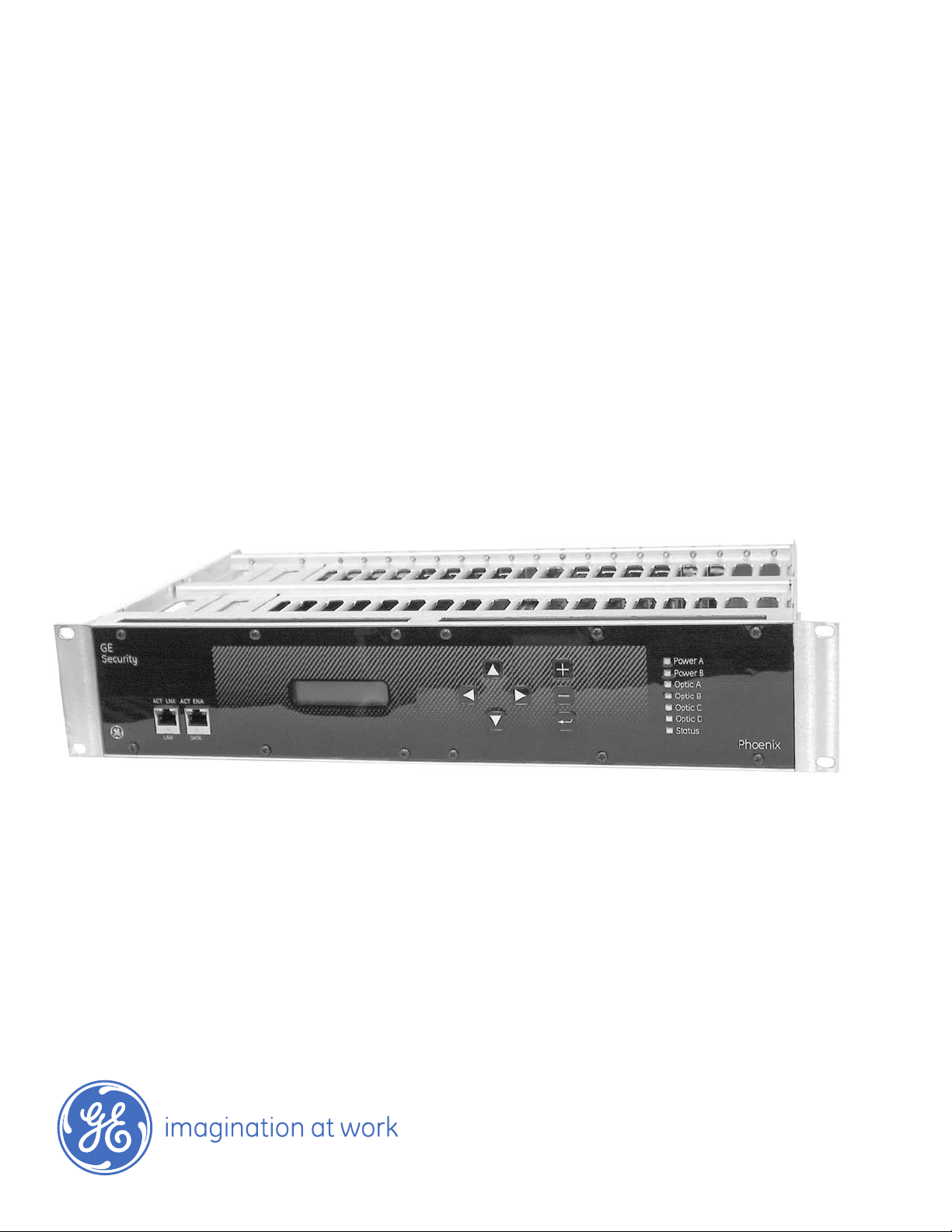
Phoenix Fiber Optic Communication System
A8950CC
installation instructions
11-A8950C
C
Page 2

Installation Instructions
EFORE YOU BEGIN
B
GETTING STARTED 2
Overview 2
etermine Mounting Configuration 2
D
Installing Power Supply 2
INSTALLING THE OPTICAL TRANSCEIVER MODULE 3
Point-to-Point, Repeater, Self-Healing Ring Diagrams 4
LED Operating Status 5
INSTALLING THE DATA MODULE 6
Configuring the Data Module 6
Install Data Module 7
Connect Data Module 7
Channel Mapping 7
Connection Instructions 8
RS-232, TTL, RS-422, RS-485, Manchester/Biphase Interface 9
RS-485, Sensornet, Test Mode 9
Data Module - Channel Sequence 10
INSTALLING THE ETHERNET MODULE 11
Install Ethernet Module 11
Connect Ethernet Module 12
INSTALLING THE VIDEO MODULE 13
Install Video Input Module 13
Install Video Output Module 13
Connection Instructions 14
Video Module - Channel Sequence 15
INSTALLING THE AUDIO MODULE 16
Configuring the Audio Module 16
Audio Input Termination Diagrams 17
Audio Input/ Output Charts 18
Audio Module - Channel Sequence 19
INSTALLING THE CONTACT CLOSURE MODULE 20
Install Contact Closure Module 20
Connection Instructions 21
RJ45, Contact Input/ Contact Output Charts 22
Contact Input/ Contact Output - Channel Sequence 22
CONFIGURING THE PHOENIX FIBER OPTIC COMMUNICATION SYSTEM 23
T
urn on power and check status 23
Select the system topology
Set the node ID
FRONT PANEL MENU TREE AND DESCRIPTIONS 27
Main Menu Options 28-31
Menu Options: Video 31-33
Menu Options: Data 34-36
Menu Options: Ethernet 37
Menu Options: Audio 38-39
Menu Options: Contact Closure 39-41
MAIN LOCAL POWER/ MAIN LOCAL TEST/ MAIN LOCAL ABOUT 41-42
MAIN REMO
ANK P
BL
OPTICAL TRANSCEIVER MODULE SPECIFICATIONS 45
DATA MODULE SPECIFICATIONS 46
THERNET MODULE SPECIFICATIONS
E
VIDEO MODULE SPECIFICATIONS 48
AUDIO MODULE SPECIFICATIONS 49
CONT
CUSTOMER SUPPORT 50
TE/ MAIN ABOUT
ANEL SPECIFICA
OSURE MODULE SPECIFICA
CT CL
A
TIONS AND LIMITED W
TIONS
ARRANT
Phoenix Fiber Optic Communication System
1
24-26
26
42-43
Y
44
47
50
Page 3

Before You Begin
Read these instructions before installing or operating this product.
Note: This installation should be made by a qualified service person and should conform to local codes.
his manual provides installation and operation information.
T
To use this document, you must have the following minimum qualifications:
• A basic knowledge of CCTV systems and components
• A basic knowledge of electrical wiring and low-voltage electrical hookups
Intended Use
Use this product only for the purpose for which it was designed; refer to the product
specification and user documentation.
Customer Support
For assistance in installing, operating, maintaining, and troubleshooting this product,
refer to this document and any other documentation provided. If you still have questions,
please contact technical support during normal business hours (Monday through Friday,
excluding holidays, between 6 a.m. and 5 p.m. Pacific Time).
GE Security
Call: 888 437-3287 (US, including Alaska and Hawaii; Puerto Rico; Canada)
Outside the toll-free area: 503 885-5700
Fax: 561 998-6224
Note: You should be at the equipment and ready with details before calling Technical Support.
Conventions Used in this Manual
Boldface or button icons highlight command entries. The following WARNING,
CAUTION, and Note statements identify potential hazards that can occur if the
equipment is handled improperly:
* WARNING:
Improper use of this equipment can cause severe bodily injury or equipment damage.
** CAUTION:
Improper use of this equipment can cause equipment damage.
Note:Notes contain impor
* This symbol indicates electrical warnings and cautions.
** This symbol indicates general warnings and cautions.
tant information about a pr
oduct or procedure.
1
Page 4
Getting Started
** CAUTION:
This product contains ESD-sensitive components. Although all precautions have been made to
reduce ESD susceptibility, use good grounding techniques when handling uninstalled modules
Overview
Installing the Phoenix chassis is a three-step process:
1. Install mounting hardware and power supplies.
2. Install modules and connect cabling.
3. Configure the system.
Determine Mounting Hardware
Mounting brackets are adjustable. Choose the best location to fit your application and
position brackets using the supplied hardware. Remove screws holding front mounting
bracket, move to top, bottom, back or front and refasten.
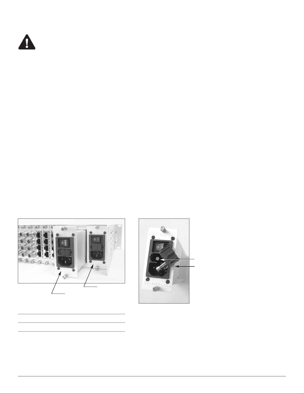
Installing Power Supplies
.
All installation should be from rear of rack unit.
To install power supply, slide power supply in slot "A" and secure with hardware. Remove
center support panel and use to cover open slot if redundant power supply is not used.
Optional Redundant Power Supply: When using the redundant power supply, remove panel
and insert second power supply in slot "B" and secure.
t Number
ar
Specifications
Model A8960AC
Size
Weight
1.65 in. W x 3.30 in. H x 8.00 in. D (42 x 84 x 203 mm)
1.25 lb
. (5.67 g)
Model
Model
Slot B
Model Part Number
Optional Redundant Power Supply
Slot A
A8960AC
.
Electrical
• Input power: 100 V to 240 V, 60 to 50 Hz
• Current requirement: 2 A
• Power consumption: 40 W
• Protection: 250 V, 2 A fuse
Model P
Model Part Number
Spare fuse
use
e f
Activ
Module Installation
The Optical Transceiver is the first module to be installed.
2
Page 5
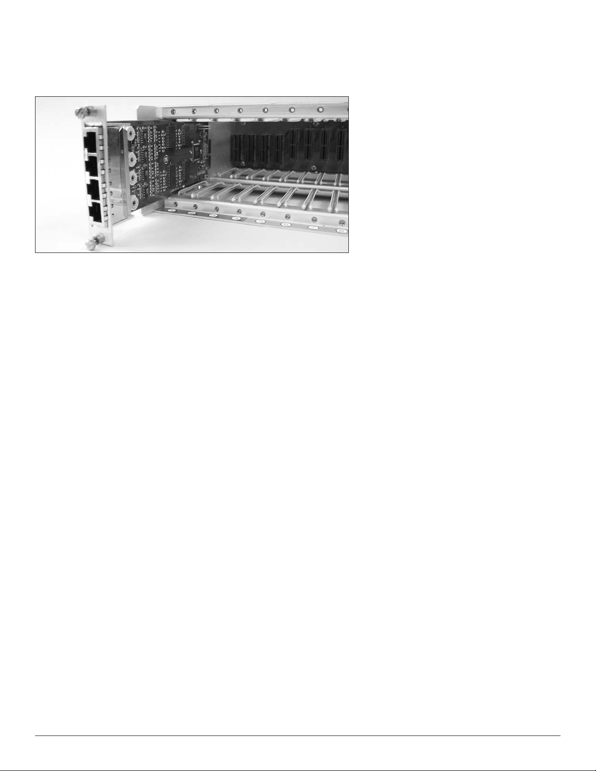
Installing the Optical Transceiver Module
Overview
The Phoenix optical transceiver module is used to provide connectivity to the fiber
connections between nodes. The A8972FLC optical transceiver module contains a single
optical transceiver with dual LC connectors and is used as an ‘end node’ in either a point
to point, or linear system. The A8974FLC optical transceiver module features two optical
transceivers with two dual LC connectors and is used in repeating nodes within a linear
system as well as all nodes in a self-healing ring system.
Tools and materials required
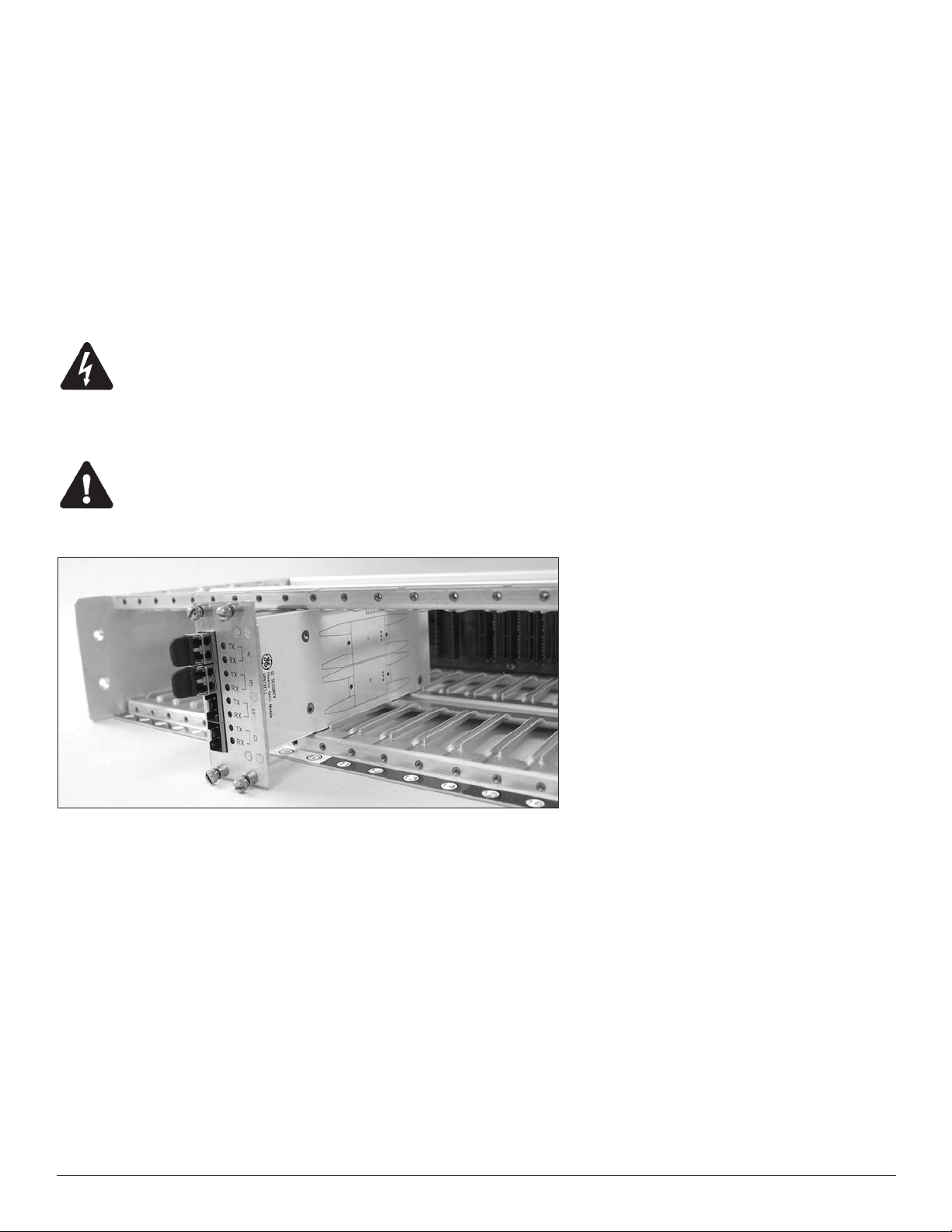
The optical module is held in place with simple thumbscrews with screwdriver slots.
The only tool recommended is a small flat blade screwdriver.
* WARNING:
Insure main power is off when installing or removing.
Installation instructions:
1. Install optical transceiver module in slots 9 and 10 (color-keyed white) and secure.
** CAUTION:
Use caution when inserting it into a slot adjacent to an existing module. It is best to install this
module in your node first, to avoid potential damage to components on the back of this module.
INSERT OPTICAL TRANSCEIVER MODULES IN SLOTS 9-10 (White)
2. Connect fiber:
Connect single-mode fiber optic cables by using LC connectors. Each port connects to a
pair of fibers. The top fiber in a port is the laser output (Tx) and the bottom fiber is the
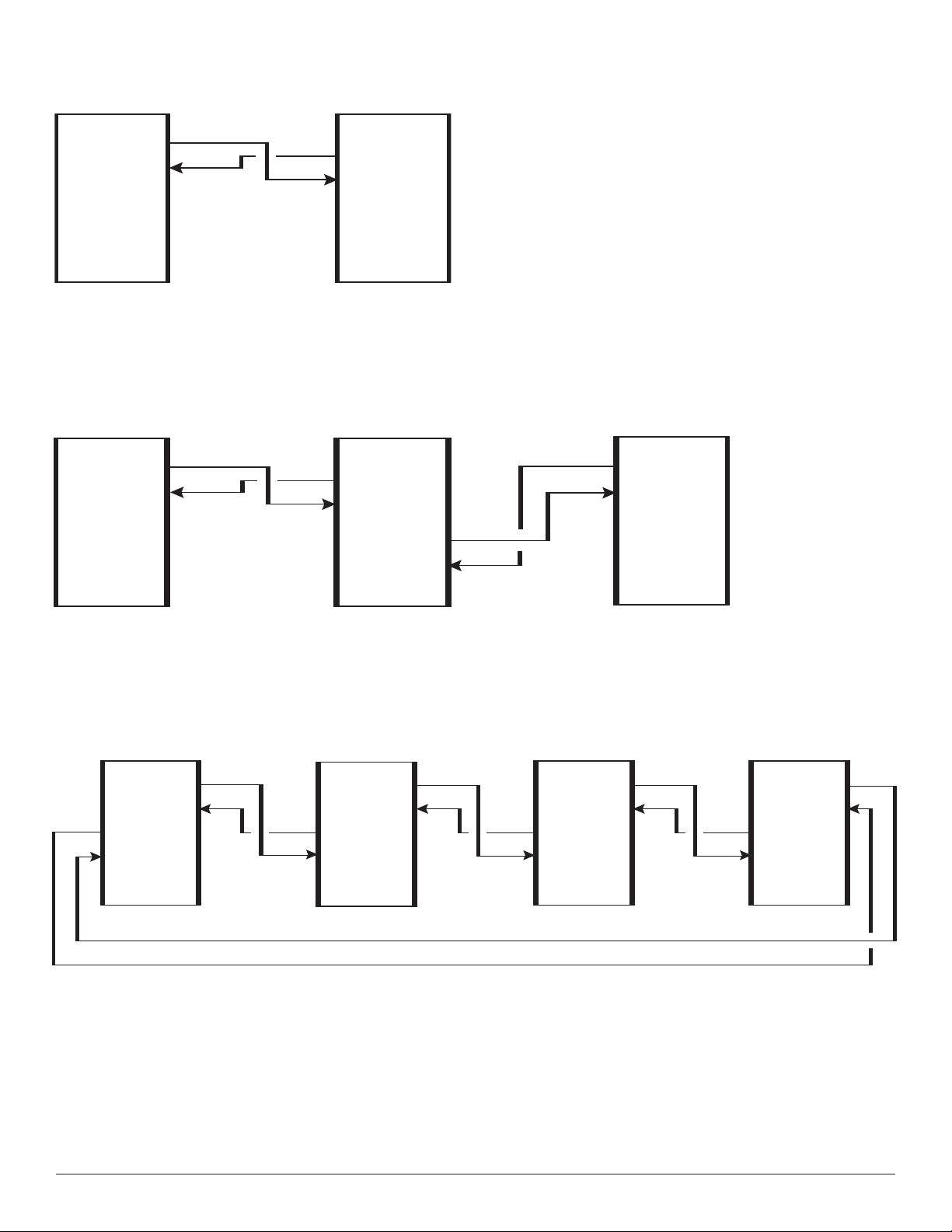
photo diode input (Rx). In a point-to-point system, connect the optic in port A from the
first node to the optic in port A in the second node. Remember that the two fibers need
to be crossed, so that the laser output on one node is connected to the photodiode
input in the other node. This can be verified by observing the corresponding LEDs as
shown in the table below.
In a linear system, connect the fiber to Optic A in the end node (node with only one
fiber transceiver) to Optic B in the subsequent node. Repeat until the ‘headend’ node
is reached, where the fiber must go into Optic A .
In self-healing ring systems, simply connect Optic A from one node to Optic B on the
next node, throughout the ring.
3
Page 6
Point-to-Point Connect
Tx A
Rx A
A8972FLC
x A
T
Rx A
A8972FLC
Repeater Connect
Tx A
Rx A
A8972FLC A8972FLC
Tx A
Rx A
Tx B
Rx B
A8974FLC
Tx A
Rx A
HEAD END MIDDLE NODES
Self-Healing Connect
Tx A
Rx A
Tx B
Rx B
A8974FLC A8974FLC A8974FLC A8974FLC
Tx A
Rx A
Tx B
Rx B
Tx B
Rx B
FIELD END NODE
Tx A
Rx A
x B
T
Rx B
Tx A
Rx A
4
Page 7

3. Verify fiber connectivity:
Using the LEDs on the back of the unit adjacent to the optic module, verify proper
operation as shown in the table below. Both optical launch power and optical receive
power, as well as transceiver status, can be verified from the LCD front panel.
LED operating status
Optic LED
RED Indicates faulty LASER or no module installed
Tx
OFF LASER operating within specifications
GREEN Indicates sufficient power received and frame synchronization
Rx
OFF Indicates insufficient optical power
5
Page 8

Installing the Data Module
Overview
The Phoenix A8910MPD data module is capable of inserting/extracting
4 channels of multiprotocol serial data (MPD) per module. With a maximum of four
cards per node, the system capacity is 16 channels. Each channel is capable of
transmitting and receiving serial data throughout the Phoenix system. The card is not
limited to any single data type so that various formats can be mixed on a single card.
As with other GE Security MPD products, data translation capabilities are included.
Tools and materials required
The data modules are held in place with simple thumbscrews with screwdriver slots.
The only tool recommended is a small flat blade screwdriver.
Installation instructions:
1. Configure data module:
Prior to installation, you must specify the appropriate data format using the rotary
switches on the module. For each channel on the data module, rotate the dial switch to
the desired format. If you want to select the data format from the front panel, leave the
switch in position 0.
Setting Mode
0 Softw
are-selectable (factory preset)
1 RS-232 (3-wire)
2 RS-232 + handshake
3 TTL
4 RS-422 2-wire
5 Manchester/biphase
6 RS-485 2-wire standard/Sensornet
7 RS-485 2-wire 1V
Setting Mode
8 RS-485 2-wire 2 V
9 RS-485 4-wire standard
A RS-485 4-wire 1 V
B RS-485 4-wire 2 V
C Reserved
D Reserved
E Reserved
F Test Mode
NOTE: The DATA SELECT switches are shipped in the Software-Selectable setting.
As with all GE Security MPD products, data translation can easily
be accomplished using the table information below.
Translation
TTL RS-232, 3-wire
RS-232, 3-wire TTL
TTL RS-422
RS-422 TTL-wire
RS-232, 3-wir
e RS-422
Input
3
1
3
4
1
Output
1
3
4
3
4
Comment
Signal level conversion.
Signal level conversion.
Single ended to differential conversion.
Differential to single ended conversion.
Single ended to differ
ential conv
ersion.
RS-422 RS-232, 3-wire
RS-232, 5-wire RS-485
RS-485 RS-232, 5-wire
4
2
7 - A
1
7 - A
2
sion.
ential to single ended conv
Differ
RS232 Handshaking bit is used to indicate Tri-state.
Tri-state detection circuitry activates handshaking bit.
er
6
Page 9
2. Install data module:
Up to four data modules can be installed in the Phoenix node.
From left, locate and insert data modules into slot 1, 2, 3, or 4
(color-keyed red) and secure.
INSERT DATA CARDS IN SLOTS 1-4 (Red)
3. Connect:
Each data module is shipped with (four) RJ45 cables and (four) breakout boxes to aid in
connecting to the Phoenix. Use the tables below to determine pinout information for
your application. GE Security recommends using shielded cable for all single ended
applications and twisted shielded cable for all differential formats. Wire gauge is
dependent on copper run length. Refer to manufacturer of data equipment for
specific recommendations. Once the data equipment has been connected, confirmation
of data activity can be verified on the front panel LCD.
The channel order is sequential, beginning with the top RJ45 in slot 1 as Channel 1,
working vertically such that the bottom RJ45 in slot 1 is Channel 4, and the top RJ45 in
slot 2 is Channel 5. This continues to the bottom RJ45 in slot 4, which is mapped to
Channel 16.
7
Page 10
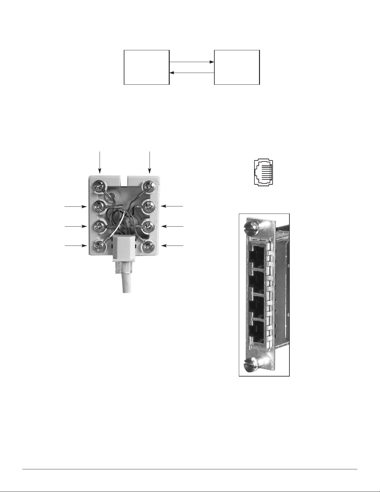
D
ATA EQUIPMENT
F
IBER LINK
Pin
1 8
DATA OUT
DATA IN
DATA IN
DATA OUT
igure 1. Fiber Link Data Connections
Pin
1 8
F
Figure 1. Terminal Block Pin Assignments
5
6
7
8
4
3
2
1
Using the breakout box
A breakout box with a 3’ CAT 5 patch cord
(supplied) can be used to interface to the
Phoenix system. Pinouts are shown in the
tables and figures above.
Figure 2. RJ45 Socket
(Viewed from the rear of the unit)
RJ45-A
RJ45-B
RJ45-C
RJ45-D
8
Page 11

NOTE: When making data connections listed in Tables 3 through 11, always connect the pins labeled IN
on the fiber unit to the pins labeled OUT on the external equipment, and the pins labeled IN on the
external equipment to the pins labeled OUT on the fiber unit.
ABLE 4: RS-232 WITH HANDSHAKING INTERFACE
TABLE 3: RS-232 INTERFACE
ATA SELECT Switch: Position 1
D
T
DATA SELECT Switch: Position 2
Pin
1
2
3
4
5
6
7
8
TABLE 5: TTL INTERFACE
DATA SELECT Switch: Position 3
Pin
1
2
3
4
Signal
RS-232 Out
N/C
GND/SHIELD
N/C
N/C
GND
N/C
RS-232 In
Signal
N/C
TTL Out
GND/SHIELD
N/C
Pin
1
2
3
4
5
6
7
8
TABLE 6: RS-422 INTERFACE
DATA SELECT Switch: Position 4
Pin
1
2
3
4
Signal
RS-232 Out
RTS/CTS Out
GND/SHIELD
N/C
N/C
GND
RTS/CTS In
RS-232 In
Signal
RS-422 Out (+)
RS-422 Out (-)
GND/SHIELD
N/C
5
6
7
8
TABLE 7: MANCHESTER/BIPHASE INTERFACE
DATA SELECT Switch: Position 5
Pin
1
2
3
4
5
6
7
8
N/C
GND/SHIELD
TTL In
Tie to pin 6
Signal
Manchester/Biphase Out (+)
N/C
Manchester/Biphase Out (-)
N/C
ermination, tie to 8 if req’d.
T
GND/SHIELD
Manchester/Biphase In (-)
Manchester/Biphase In (+)
5
6
7
8
T
ABLE 8: RS-485 2-WIRE INTERFACE
DATA SELECT Switch: Position 6 (<200mV),
osition 7 (<1V), P
P
Pin
1
2
3
4
5
6
7
8
Termination, tie to 8 if req’d.
GND/SHIELD
RS-422 In (-)
RS-422 In (+)
osition 8 (<2V)
Signal
N/C
N/C
GND
+5 VDC Bias Out
Termination, tie to 8 if req’d.
GND/SHIELD
RS-485 (-)
RS-485 (+)
9
Page 12

TABLE 9: RS-485 4-WIRE INTERFACE
DATA SELECT Switch SW1:
osition 9 = standard offset
P
osition A = 1V offset
P
Position B = 2V offset
TABLE 10: SENSORNET INTERFACE
DATA SELECT Switch: Position 6
Pin
1
2
3
4
5
6
7
8
TABLE 11: TEST MODE LOOPBACK INTERFACE
DATA SELECT Switch: Position F
Pin
1
2
Signal
RS-485 Out (+)
RS-485 Out (-)
GND/SHIELD
+5 VDC Bias Out
Termination, tie to 8 if req’d.
GND/SHIELD
RS-485 In (-)
RS-485 In (+)
Signal
Tie to pin 8
Tie to pin 7
Pin
1
2
3
4
5
6
7
8
Signal
N/C
N/C
GND
N/C
Termination, tie to 8 if req’d.
GND/SHIELD
Sensornet (-)
Sensornet (+)
3
4
5
6
7
8
N/C
N/C
N/C
N/C
Tie to pin 2
Tie to pin 1
Data module - channel sequence
Slot 1
RJ45-A Ch 1 IN/OUT
RJ45-B
Ch 2 IN/OUT
RJ45-C Ch 3 IN/OUT
RJ45-D Ch 4 IN/OUT
Slot 2
Ch 5 IN/OUT
Ch 6 IN/OUT
Ch 7 IN/OUT
Ch 8 IN/OUT
Slot 3
Ch 9 IN/OUT
Ch 10 IN/OUT
Ch 11 IN/OUT
Ch 12 IN/OUT
Slot 4
Ch 13 IN/OUT
Ch 14 IN/OUT
Ch 15 IN/OUT
Ch 16 IN/OUT
10
Page 13
Installing the Ethernet Module
Overview
The Phoenix A8911ETH Ethernet module provides Ethernet connectivity to the Phoenix
system. Each module has three RJ-45 ports supporting full-duplex 10/100Base-T interfaces.
Each port also supports Auto-Negotiation and automatic MDI/MDI-X selection.
Unlike other modules used in the Phoenix system, the ethernet module does not use “channels”. Each slot position provides access to one of four independent Ethernet
networks. Every port on a module can communicate with every other port on other
modules connected to the same network (i.e. modules plugged into the same slot number
at different nodes). There is no restriction to the number of modules connected to a
network, however they must share bandwidth between nodes. Each network can sustain
25Mbps throughput between nodes.
Note: Ethernet is inherently a bi-directional communication protocol. Therefore all nodes in
a Phoenix system with Ethernet modules must be connected with duplex fiber connections.
Simplex connections between nodes will cause the network to fail.
Tools and materials required
The Ethernet modules are held in place with simple thumbscrews with screwdriver slots.
The only tool r
ecommended is a small flat blade screwdriver.
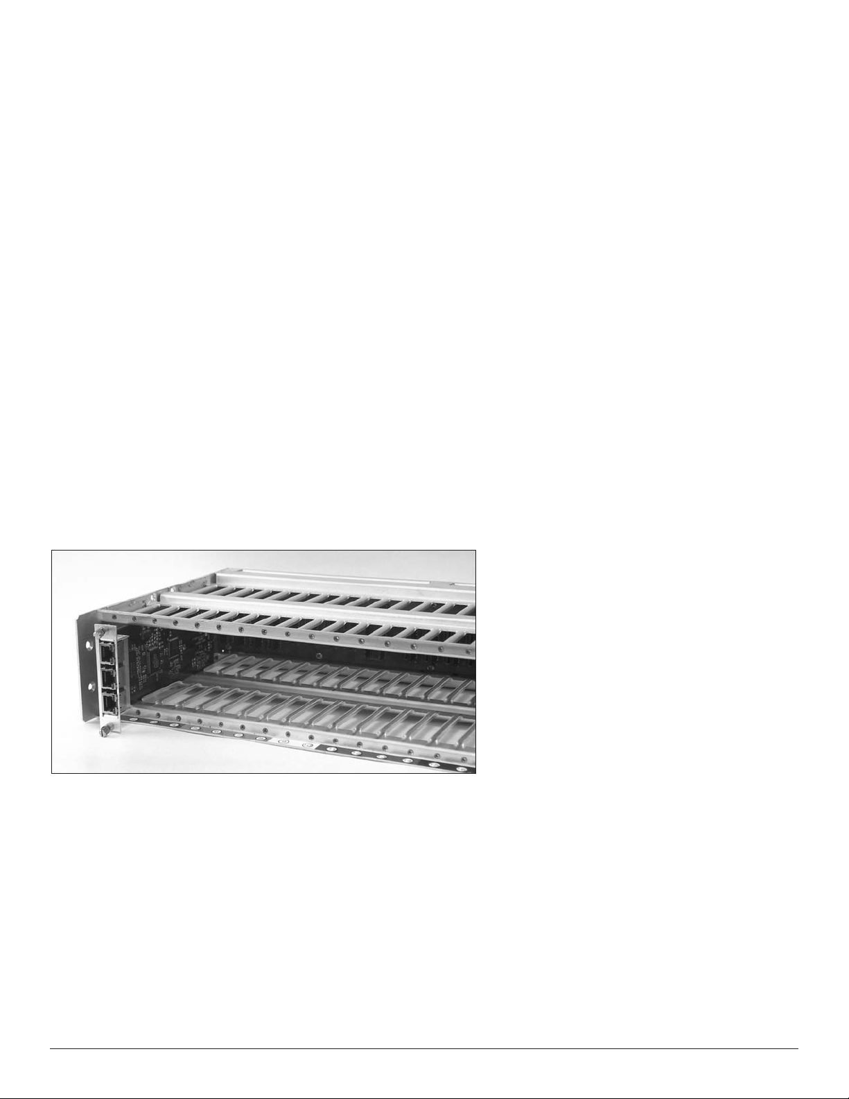
Installation instructions:
1. Install the Ethernet module:
Up to four Ethernet modules can be installed in the Phoenix node. From left, locate and
insert Ethernet modules into slot 1, 2, 3, or 4 (color-keyed red) and secure.
INSERT ETHERNET MODULES IN SLOTS 1-4 (Red)
11
Page 14

2. Connect:
Connect Ethernet-capable equipment directly to the Ethernet module using CAT5 twistedpair cables with male RJ-45 connectors at both ends. Do not use breakout boxes.
Standard CAT5 cabling used for Ethernet is available with either straight-through or
crossover connections. Either variety may be used with the Ethernet module. The
auto-MDI/MDI-X feature of each port automatically detects the type of cable
connection to establish link.
3. Configure:
At power-up, every port has Auto-Negotiation enabled. This should work seamlessly
with most Ethernet equipment. However, if necessary, Auto-Negotiation, Link Speed
and Duplex can be configured manually via the Phoenix chassis’s front panel.
Refer to the section Front Panel Menu Tree and Descriptions for more information.
12
Page 15
Installing the Video Module
Overview
The Phoenix A8900VI input module is capable of inserting up to four baseband,
composite video signals per card. A maximum of four cards can be installed in any node,
allowing up to 16 inputs per node.
The Phoenix A8905VO output module is capable of outputting up to 4 base band, composite
video signals per card. A maximum of four cards can be installed in any node, allowing up
to 16 outputs per node.
Tools and materials required
The video modules are held in place with simple thumbscrews with screwdriver slots.
The only tool recommended is a small flat blade screwdriver.
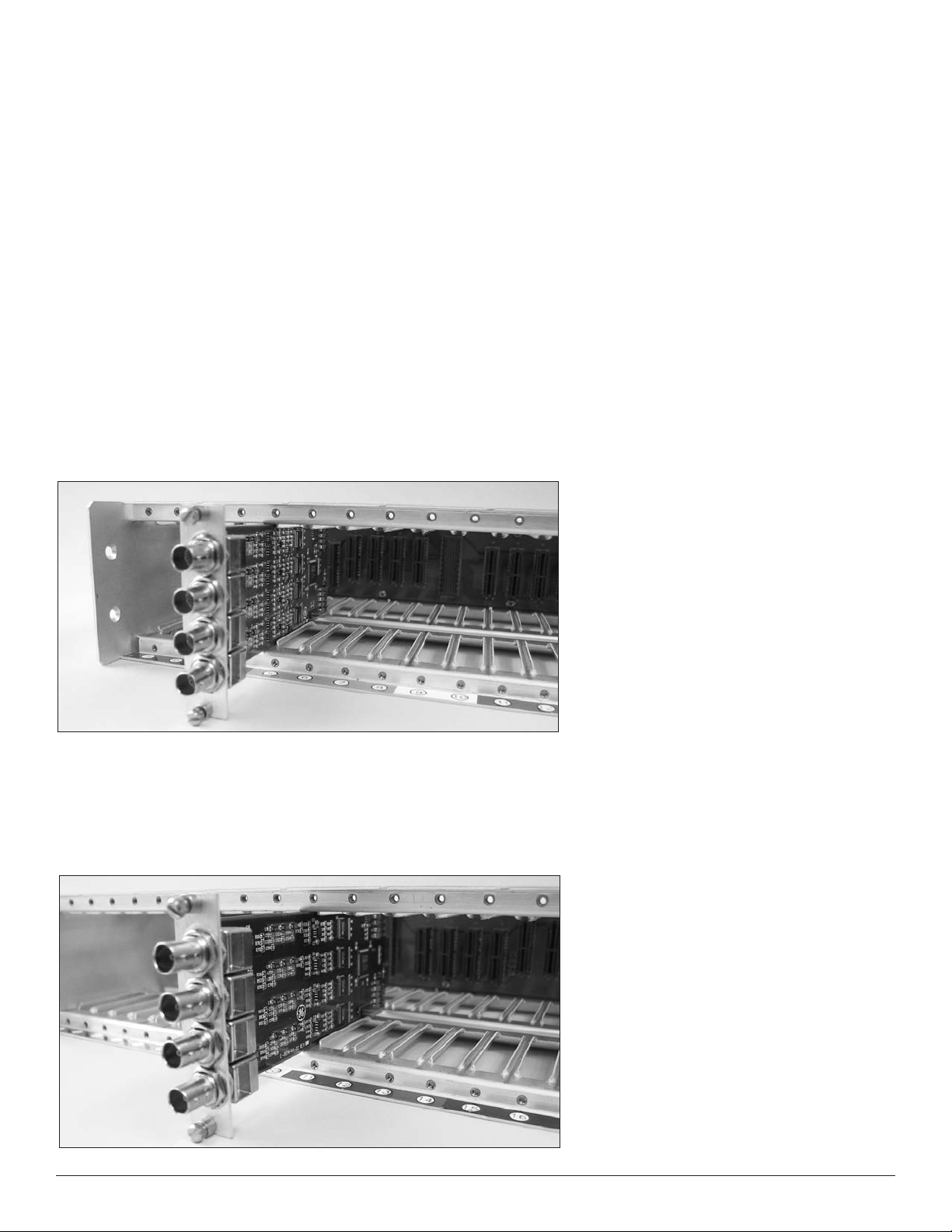
Installation instructions:
1. Install video input module:
As shown below, install video Input modules in slots 5, 6, 7, or 8 (color-keyed green)
and secure. Up to four modules may be installed per Phoenix node. Up to four incoming
video signals can be installed per module by connecting to BNC mounts (four) on each card.
INSERT VIDEO INPUT MODULES IN SLOTS 5-8 (Green)
2. Install video output module:
As shown below, install video output modules in slots 11, 12, 13, or 14 (color-keyed blue)
and secure. Up to four modules may be installed per Phoenix node. Up to four outgoing
video signals for monitoring or recording can be installed per module by connecting to
BNC mounts (four) on each card.
INSERT VIDEO OUTPUT MODULES IN SLOTS 11-14 (Blue)
13
Page 16

Connection instructions
Video Inputs:
Connect video source equipment such as cameras or matrix switcher outputs to the
video input modules using the BNCs on the back of the panel. Confirmation of video
presence can be confirmed on the front panel LCD. The channel order is sequential,
beginning with the top BNC in slot 5 as Channel 1, working vertically such that the
bottom BNC in slot 5 is assigned Channel 4, and the top BNC in slot 6 is
assigned Channel 5. This continues to the bottom BNC in slot 8, which is mapped
to Channel 16.
Video Outputs:
Connect video monitoring equipment including monitors and recording devices, to
the video output cards using the BNCs on the back of the panel. Confirmation of video
output can be confirmed on the front panel LCD. As with the inputs cards, the channel
order is sequential, beginning with the top BNC in slot 11 as Channel 1, working vertically
such that the bottom BNC in slot 11 is assigned Channel 4, and the top BNC in slot 12 is
assigned Channel 5. This continues to the bottom BNC in slot 14, which is Channel 16.
14
Page 17

Video Input module - channel sequence
lot 5
S
BNC A Ch 1 IN
Slot 6
Ch 5 IN
Slot 7
Ch 9 IN
Slot 8
Ch 13 IN
BNC B Ch 2 IN
BNC C Ch 3 IN
BNC D Ch 4 IN
Ch 6 IN
Ch 7 IN
Ch 8 IN
Video Output module - channel sequence
Slot 11
BNC A Ch 1 OUT
BNC B Ch 2 OUT
BNC C Ch 3 OUT
BNC D Ch 4 OUT
Slot 12
Ch 5 OUT
Ch 6 OUT
Ch 7 OUT
Ch 8 OUT
Ch 10 IN
Ch 11 IN
Ch 12 IN
Slot 13
Ch 9 OUT
Ch 10 OUT
Ch 11 OUT
Ch 12 OUT
Ch 14 IN
Ch 15 IN
Ch 16 IN
Slot 14
Ch 13 OUT
Ch 14 OUT
Ch 15 OUT
Ch 16 OUT
BNC A
BNC B
BNC C
BNC D
15
Page 18

Installing the Audio Module
Overview
The Phoenix A8920A audio module is capable of inputting and outputting up to 4 audio
channels. The audio module occupies one audio slot (color coded black) and with up to
four slots available, each node has a capacity of 16 channels. The audio interface
connector is four, ganged RJ45 connectors located on each card. The audio module
supports an audio test pattern, similar to GE Security standards.
Tools and materials required
The audio modules are held in place with simple thumbscrews with screwdriver slots.
The only tool recommended is a small flat blade screwdriver.
Installation instructions:
1. Configure audio module:
Prior to installation, the audio modules need to be configured for proper
use in the system. Refer to the Fig. 1 and Fig. 2 for switch locations and settings.
a. Input termination: Input termination should be set depending on your system
requirements. You can choose either high-impedance (default) or 600 ohm
termination on an individual channel basis.
b. Input range: Based on the level of input signal you will be applying the
specific channel, you may choose to modify the input range selection switches.
By default, the switches are set to high range (+18dBu) and will transmit any
audio signal within the specifications of the unit. If lower level input signals are
expected, you may change the input range to low (+8dBu) to increase the overall
signal to noise ratio. Clipping (distortion) however, will occur if input levels exceed
+8dBu. Note that for each channel, two switches must be thrown to change
the input range.
c. Output range: To normalize the system, you must switch the output range
switch to the same setting as the CORRESPONDING input range switch. Note, this
does not mean that the switches on the same board need to be the same, just
that the switches at the input node, must match the switches at the output node.
If multiple outputs are mapped (broadcast mode) than all outputs must be set to
the same gain range.
UDIO INPUT
A
TERMINATION
AUDIO OUTPUT
RANGE
AUDIO INPUT
RANGE
Figure 1. Audio Level Switch Locations
16
Page 19

AUDIO INPUT TERMINATION
Note: One switch per channel
AUDIO INPUT RANGE
Note: Two switches per channel
AUDIO OUTPUT RANGE
Note: One switch per channel
N
O
S1
Ch A
Ch B
High Z
ON
S2
High Z
600Ω
Ch C
Ch D
600Ω
The A8920A units are shipped
with the input impedance set
at (high-Z). To select a 600Ω
input impedance in place of the
high-Z input, set switches SW1
and SW2 on the audio to 600Ω.
Figure 2. Audio Level Switch Positions
S3
S4
S5
S6
Low
Low
Low
O
ON
ON
ON
N
High
High
High
Ch A
Ch B
Ch C
N
O
S7
Ch A
Ch B
Low
S8
Low
High
ON
Ch C
Ch D
High
If a low audio level causes the output
audio signal to degrade, the input
sensitivity of the A8920A can be
increased by switching to the 8 dBu
maximum scale.
You can set the transmitter input to
8 dBu and the receiver output to 18
dBu to add 10 dB of gain to the
system, however, this also increases
system signal-to-noise ratio (S/N).
Ch C
Low
High
2. Installing audio modules:
Audio modules must be installed in slots 15, 16, 17, or 18 (color coded black).
Up to four Audio modules can be installed per Phoenix node.
The channel sequence is as follows:
Slot 15, top RJ45 connector is assigned to Channel Inputs 1 and 2.
The second RJ45 connector gets assigned to Channel Inputs 3 and 4.
The third RJ45 connector gets assigned to Channel Outputs 1 and 2.
The bottom RJ45 connector gets assigned to Channel Outputs 3 and 4.
Subsequent modules, placed in slots 16, 17, and 18 are assigned
to Channels 5-8, 9-12, and 13-16 respectively.
17
Page 20

INSERT AUDIO CARDS IN SLOTS 15-18 (Black)
3. Connecting to audio modules:
GE Security recommends connecting to the terminal block using high-quality shielded,
twisted-pair wire for best audio performance.
The I/O for the audio inputs and outputs are as follows:
RJ45 - A (Top) AUDIO INPUTS - CHANNELS A-B
Pin
1
2
3
4
5
6
7
8
RJ45 - C AUDIO OUTPUTS - CHANNELS A-B
Pin
1
2
3
Audio Signal
IN A (+)
IN A (-)
GND/SHIELD
GND
GND
GND/SHIELD
IN B (+)
IN B (-)
Audio Signal
OUT A (+)
OUT A (-)
GND/SHIELD
RJ45 - B AUDIO INPUTS - CHANNELS C-D
Pin
1
2
3
4
5
6
7
8
RJ45 - D (Bottom) AUDIO OUTPUTS - CHANNELS C-D
Pin
1
2
3
Audio Signal
IN C (+)
IN C (-)
GND/SHIELD
GND
GND
GND/SHIELD
IN D (+)
IN D (-)
Audio Signal
OUT C (+)
OUT C (-)
GND/SHIELD
4
5
6
7
8
GND
GND
GND/SHIELD
OUT B (+)
OUT B (-)
4
5
6
7
8
GND
GND
GND/SHIELD
OUT D (+)
OUT D (-)
18
Page 21

P
in
1 8
Figure 1. Terminal Block Pin Assignments
5
4
Figure 2. RJ45 Socket
Viewed from the rear of the unit)
(
6
7
8
3
2
1
Using the breakout box
A breakout box with a 3’ CAT 5 patch cord
(supplied) can be used to interface to the
Phoenix system. Pinouts are shown in the
tables and figures above.
RJ45-A
RJ45-B
RJ45-C
RJ45-D
Audio module - channel sequence
Slot 15
RJ45-A Ch 1-2 IN
RJ45-B Ch 3-4 IN
RJ45-C Ch 1-2 OUT
RJ45-D Ch 3-4 OUT
Slot 16
Ch 5-6 IN
Ch 7-8 IN
Ch 5-6 OUT
Ch 7-8 OUT
Slot 17
Ch 9-10 IN
Ch 11-12 IN
Ch 9-10 OUT
Ch 11-12 OUT
Slot 18
Ch 13-14 IN
Ch 15-16 IN
Ch 13-14 OUT
Ch 15-16 OUT
19
Page 22

Installing the Contact Closure Module
Overview
The Phoenix A8930C contact closure module is capable of supporting up to
8 contact closure inputs, and 8 contact closure outputs per module. With up to 4
modules available per system, up to 32 contact inputs and outputs can be transmitted.
Contact closure modules are color coded black, and can be installed in slots 15, 16, 17,
or 18. The input/output interface is four, ganged RJ45 connectors located on each card,
See contact closure pin-out connection in Fig. 2.
Tools and materials required
The contact closure modules are held in place with simple thumbscrews with screwdriver
slots. The only tool recommended is a small flat blade screwdriver.
Installation instructions:
1. Install contact closure module:
Install contact closure modules in slots 15, 16, 17, or 18 (color-coded black) and secure.
Up to four contact closure modules can be installed in each node. Connect contact
closure wires to terminal blocks on each card by using the RJ45 connectors.
The channel sequence is as follows:
Slot 15, top RJ45 connector is assigned to Channel Inputs 1, 2, 3, and 4.
The second RJ45 connector gets assigned to Channel Inputs 5, 6, 7, and 8.
The third RJ45 connector gets assigned to Channel Outputs 1, 2, 3, and 4.
The bottom RJ45 connector gets assigned to Channel Output 5, 6, 7, and 8.
Subsequent modules, placed in slots 16, 17, and 18 are mapped
to Channels 9-16, 17-24, and 25-32 respectively.
INSERT CONTACT CLOSURE CARDS IN SLOTS 15-18 (Black)
20
Page 23

Pin
1 8
2. Connect to the module:
Each contact closure module is shipped with (four) RJ45 cables and (four) breakout
boxes to aid in connecting to the Phoenix. Use the tables below to determine pin out
information for your application. GE Security recommends using shielded cable for all
single ended applications and shielded twisted-pair for all differential formats.
Wire gauge is dependent on copper run length. Refer to manufacturer of data
equipment for specific recommendations.
Figure 1. Terminal Block Pin Assignments
5
6
7
8
4
3
2
1
Using the breakout box
A breakout box with a 3’ CAT 5 patch cord
(supplied) can be used to interface to the
Phoenix system. Pinouts are shown in the
tables and figures below.
Figure 2. RJ45 Socket
(Viewed from the rear of the unit)
RJ45-A
RJ45-B
RJ45-C
RJ45-D
21
Page 24

RJ45 - A (Top) CONTACT INPUTS - CHANNELS A-D
RJ45 - B CONTACT INPUTS - CHANNELS E-H
Pin
1
2
3
4
5
6
7
8
RJ45 - C CONTACT OUTPUTS - CHANNELS A-D
Pin
1
2
3
4
Contact Signal
N A
I
(GND)
IN B
(GND)
IN C
(GND)
IN D
(GND)
Contact Signal
C A
N/O A
C B
N/O B
Pin
1
2
3
4
5
6
7
8
RJ45 - D (Bottom) CONTACT OUTPUTS - CHANNELS E-H
Pin
1
2
3
4
Contact Signal
IN E
(GND)
IN F
(GND)
IN G
(GND)
IN H
(GND)
Contact Signal
C E
N/O E
C F
N/O F
5
6
7
8
To activate a relay, provide a connection from an IN (+) to GROUND.
C C
N/O C
C D
N/O D
Contact Input module - channel sequence
Slot 15
RJ45-A Ch 1-4 IN
RJ45-B Ch 5-8 IN
RJ45-C Ch 1-4 OUT
RJ45-D Ch 5-8 OUT
Slot 16
Ch 9-12 IN
Ch 13-16 IN
Ch 9-12 OUT
Ch 13-16 OUT
5
6
7
8
• IN
• GND
Slot 17
Ch 17-20 IN
Ch 21-24 IN
Ch 17-20 OUT
Ch 21-24 OUT
C G
N/O G
C H
N/O H
Slot 18
Ch 25-28 IN
Ch 29-32 IN
Ch 25-28 OUT
Ch 29-32 OUT
22
Page 25

Configuring the Phoenix Fiber Optic Communications System
This section explains how to configure a Phoenix chassis using the front panel. The front
panel has seven status LEDs, an LCD display, seven push buttons and two RJ-45 ports.
These RJ-45 ports (labeled LAN and DATA) are currently unused. Do NOT connect any
cables or equipment to these ports; it may damage the Phoenix chassis.
Basic configuration of a Phoenix chassis is a three-step process:
1. Turn on power and check status.
2. Select the system topology.
3. Set the node ID.
If your system requires non-default settings (e.g. channel mapping, PAL video, etc.),
please refer to the section titled FRONT PANEL MENU TREE AND DESCRIPTIONS after
you have completed the basic configuration.
If you have not already done so, install the Power Supply Module(s), Optic Module, and
any other plug-in modules (i.e. Data, Video Input, Video Output, etc.) and connect cabling
as instructed in the previous sections of this manual
23
Page 26

1. Turn on power and check status
Turn on the power to the Phoenix chassis using the switches on the Power Supply
modules. If two power supplies are installed, turn on both switches. The LEDs perform a
brief test when the chassis powers up: all seven LEDs turn green and then turn red. After
the test has completed the LEDs indicate the status of the power supplies and optics.
Power A and Power B: If a module is installed, and the power switch is on, and the
supply is working properly the corresponding LED will be green. If the supply is installed,
but the power switch is off or a problem has been detected the LED will turn red.
If either power supply slot is empty then the corresponding LED will be off.
Optic A and Optic B: If an optic transceiver is installed in one of the top two Optic
Module transceiver slots, the corresponding LEDs indicate the status of the following
conditions:
1. The transmit laser is working properly.
2. The receive photodiode detects sufficient light over the fiber.
3. The receiver detects another Phoenix node at the other end of the fiber.
If all three of these conditions are true, then the LED will be green. If any of these
conditions is not true, then the LED will be red. If an optic transceiver module slot is
empty, then the LED will be off.
Optic C and Optic D: These LEDs are unused. After the power-on test,
they will always be off.
Status: This LED indicates the status of the ring when the Phoenix system is configured
as a Self-Healing Ring (SHR). If the ring is complete (no fiber breaks) the LED will be green.
If a single fiber break is detected the LED turns amber/orange. If a double fiber break is
detected the LED turns red. Note that a single fiber break will not result in a loss of video,
audio, or data. A double fiber break
may result in lost video, audio, or data. The LED is off
if the system is a Linear topology.
2. Select the system topology
In order for a Phoenix chassis to r
oute information over its fiber links correctly, it must
know the topology of the entire system. A chassis can be part of either a Linear or
Self-Healing Ring topology. If you are configuring a Self-Healing Ring topology, then
each node must also know the total length of optical fiber used in the ring. Once set,
the topology (and ring length) will be remembered if the chassis loses power.
24
Page 27

The topology and node ID are set using the front panel LCD display. The LCD displays a
GE SECURITY
Phoenix
Main Menu
1. Local
2. Remote
3. About
Local Menu
1. Node: 0 - Linear
2. Optics AB
3. Video 1/0 - 4/0
menu from which sub-menus or features can be selected. The push buttons allow you to
navigate through the menus. A small black arrow is used as a cursor. The "up" and
"down" buttons move the cursor up or down one line in the menu, respectively. The
"enter" button selects the sub-menu or feature at which the cursor is pointing. The "left"
button takes you back up one level in the menu hierarchy. The remaining three buttons,
"right", "+", and "-" are menu-specific and are described later.
A brief initialization routine is displayed on the LCD when the chassis powers up.
A splash screen showing the GE logo and Phoenix product name is displayed after
the routine completes. After approximately one minute of inactivity the LCD display
will turn off. The display can be re-enabled by pressing any of the seven buttons on
the front panel.
If the splash screen is displayed or if the display is blank press the "enter" button one
time. This will bring up the Main Menu. If any other menu is displayed, then press the
"left" button until the Main Menu is shown:
Use the "up" and "down" buttons to move the cursor to "1. Local".
Press the "enter" key to select the Local Menu:
25
Page 28

Press "enter" again to select the Node Menu:
Node Menu
1
. ID - 0
2. Type - Linear
3. Load Defaults
Topology Menu
1. Linear
2. Self Healing Ring
Node ID: 0
If you are configuring a system with a linear topology, and item 2 in the menu reads, "2.
Type – Linear", then you do not have to make any changes and can continue to Step 3,
below. Otherwise, select item 2 from the menu. This displays the Topology Menu:
Move the cursor to the topology of the system from the menu’s choices: Linear or SelfHealing Ring (SHR). Press "enter". A new screen will appear asking you to confirm your
choice for topology. Move the cursor to "Accept" and press "enter". The next screen will
ask you whether or not you would like to load defaults. Move the cursor to "Accept" and
press "enter". If you chose Linear then you can continue to Step 3 after you have been
returned to the Node Menu.
If you chose Self-Healing Ring, then you must also specify the length of fiber used in the
entire ring. The "+" key increments the length by 10km. The "-" key decrements the
length by 10km. Round up when selecting the ring length. Press "enter" when you are
done. You must confirm your selection on the following screen by moving the cursor to
"Accept" and pressing, "enter". The topology is now set and you are returned to the Node
Menu. Note that the topology (and ring length) is indicated on item 2 in the menu.
3. Set the Node ID.
Every Phoenix node (i.e. chassis) in a system should have a unique node ID number. The
node ID is set to 0 the first time a Phoenix chassis is switched on. This is an invalid ID; it
must be a number between 1 and 255. Once set, the node ID will be remembered if the
chassis loses pow
er.
Navigate to the Node Menu if it is
not currently displayed on the LCD.
Move the cursor to "1. ID" and press "enter":
The ID will increment by one if you press “+”. Similarly, the ID will decrement by one if
you press “-”. If you press and hold either of these buttons, the node ID will slowly
increment or decrement. The rate will increase if you continue pressing the button.
Once you have the node ID set, pres the “enter” button. Another menu will ask you
to confirm your selection. Move the cursor to “Accept” and press “enter”. The node ID is
now set and you are returned to the Node Menu. Note that the node ID is now shown
after “1. ID” in the menu.
Congratulations! You have completed the basic configuration. If your system requires
non-default settings (e.g. channel mapping or PAL video), or if you would like to learn
more about the available menus and features refer to the following section.
26
Page 29

FRONT PANEL MENU TREE AND DESCRIPTIONS
The menus accessible from the front panel are shown in the menu tree below:
Navigating through the menu tree is accomplished using the push buttons and LCD
display. The LCD shows menus from which sub-menus or features can be selected.
A small black arrow is used as a cursor. The "up" and "down" buttons move the cursor up
or down one line in the menu, respectively. The "enter" button selects the sub-menu or
feature at which the cursor is pointing. The "left" button takes you back up one level in
the menu hierarchy. The remaining three buttons, "right", "+", and "-" are menu-specific
and are described later.
27
Page 30

Main Menu:
Main Menu
1. Local
2. Remote
3. About
Local Menu
1. Node: 1 - Linear
2. Optics AB
3. Video 1/0 - 4/0
Node Menu
1. ID - 3
2. Type - Linear
3. Load Defaults
The menus accessible from the front panel are shown in the menu tree below:
Pressing any key from the opening screen will take you to the Main Menu.
Main -> Local:
There are nine selections available to configure and monitor the local node.
Some of the choices show information regarding the node or the modules installed:
1. Node: Shows node ID, topology (and ring length if SHR).
2. Optics: Shows optic ports that have transceivers installed.
3. Video I/O: Shows the number of input and output video channels installed.
4. Data: Shows the number of installed data channels.
5. Audio: Shows the number of installed audio channels.
6. Contacts: Shows the number of installed contact channels.
7. Power: Shows which power supplies are installed.
8. Test
9. About
Only three of the menu choices are visible on the LCD at one time. Pressing the "down"
button when the cursor is at the bottom of the screen will display the next three menu
choices. Similarly, pressing the "up" button when the cur
sor is at the top of the screen
will display the previous three menu choices.
Main -> Local -> Node:
28
Page 31

The Node Menu shows the node ID and topology.
Node Menu
1. ID - 3
2. Type - Linear
3. Load Defaults
Topology Menu
1. Linear
2. Self Healing Ring
Main -> Local -> Node -> ID
Every Phoenix node (i.e. chassis) in a system must have a unique node ID number.
The node ID is set to zero the first time a Phoenix chassis is switched on, or if you Load
Defaults. Zero is an invalid node ID; it must be a number between 1 and 255.
Once set, the node ID will be remembered if the chassis loses power.
The ID will increment by one if you press "+". Similarly, the ID will decrement by one
if you press "-". If you press and hold either of these buttons, the node ID will slowly
increment or decrement. The rate will increase if you continue pressing the button.
Once you have the node ID set, press the "enter" button. You will be asked to
confirm your selection.
Main -> Local -> Node -> Topology
In order for a Phoenix chassis to route information over its fiber links correctly, it must
know the topology of the entire system. A chassis can be part of either a Linear or
Self-Healing Ring topology. If you are configuring a Self-Healing Ring topology, then
each node must also know the total length of optical fiber used in the ring.
Once set, the topology will be remembered if power to the chassis is lost.
Select the topology of the system from the menu’s choices: Linear and Self-Healing Ring
(SHR). A new screen will appear asking you to confirm your choice for topology. Note
that SHR is an acronym for Self-Healing Ring used throughout the menus. The next
screen will ask you whether or not you would like to load defaults.
IMPORTANT: If you
choose to load defaults, the node ID will be set to zero and all channel mapping
information for this node will be lost. Select cancel if you do not wish to load defaults.
If you chose Linear then you are returned to the Node Menu after you confirm your
selection. If you chose Self-Healing Ring, then you must also specify the length of fiber
used in the entire ring. The "+" key increments the length by 10km. The "-" key
decrements the length by 10km. Round up when selecting the ring length. Press
"enter" when you are done. You must confirm your selection before continuing.
29
Page 32

Main -> Local -> Node -> Load Defaults
Optic Menu
1. Transmit
2. Receive
3. Info
Tx Optic B C D
4.23 mW
Status: Good
A
Rx Optic: ABCD
3.97 mW
Status: Good
This feature sets the node ID back to zero and clears all channel mapping information
for this node. The topology is retained.
Main -> Local -> Optics:
Information about the fiber optic transceivers can be accessed from the sub-menus.
Main -> Local -> Optics -> Transmit:
This screen shows the optical launch power of the selected optic transceiver. Use the "+"
button to select the next transceiver. Use the "-" button to select the previous transceiver.
The launch power is displayed in milliwatts (mW). Values around +4mW are normal.
Additionally, the transceiver transmit (TX) status is displayed. The status is reported as
either Good, Faulty, or Not Found if the selected transceiver is not installed.
Main -> Local -> Optics -> Receive:
This screen shows the optical receive power of the selected optic transceiver. Use the "+"
button to select the next transceiver. Use the "-" button to select the previous transceiver.
The power is displayed in milliwatts (mW). The receive power can be used to verify path
loss if the transmit launch power at the other end of a fiber is known. Sensitivity must be
greater than 0.04 mW to insure enough optical power is being received. Additionally, the
transceiver receive (RX) status is displayed. The status is reported as Good, Sync Loss,
Signal Loss or Not Found if the selected transceiver is not installed.
30
Page 33

Main -> Local -> Optics -> Info:
Video Menu
1. Input Mapping
2. Output Mapping
3. Test Select
Optic Info: ABCD
W
avelength: 1310 nM
Max Distance: 15 km
Vendor: Infineon
Video:
Exit
A
B
1
1
1
The Info Menu shows the wavelength (normally 1310nM), maximum distance
(normally 15km) and optic transceiver vendor name (Infineon) for the selected
optic transceiver. Use the "+" button to select the next transceiver. Use the "-" button
to select the previous transceiver.
Main -> Local -> Video:
Video Input and Video Output mapping, monitoring, and tests can be accessed from the
sub-menus.
Main -> Local -> Video -> Input Mapping:
This screen allows you to assign a video input channel to a video output channel over a
selected fiber port. The camera icon in the middle of the screen indicates the presence
of a video signal for the selected channel. If the camera has an X through it, video is not
present on this channel. If the camera does not have an X through it, then video is
present. The number under the camera icon indicates the currently selected input
channel. The numbers under the monitor icons to the left and/or right of the camera
represent the output channel numbers. The arrows to the left and/or right of the
camera (labeled A and B, respectively) indicate over which fibers this mapping is
enabled. If the selected input channel is mapped to the output channel then a black
square is shown in the middle of the monitor icon and the arrow is displayed. If a
mapping does not exist for this input and output channel pair, then the monitor icon
is blank and the arrow is not shown.
Use the "left" and "right" button to move the cursor at the bottom of the screen. Use "+"
and "-" to increment and decrement the channel numbers. Incrementing the input
channel automatically increments both output channels. Pr
at an output channel to enable a mapping. Move the cursor to "Exit" and press enter to
leave this screen. All channel mapping are saved when you leave this menu.
ess "enter" while the cursor is
31
Page 34

When a Phoenix node is initially configured (or if Load Defaults is selected from the Node
Video:
Exit
A
B
A
B
1
Video:
Exit
A
B
A
B
1
Video:
Exit
A
B
A
B
1
Menu), every input channel is mapped to the output channel of the same number (e.g.
input channel 1 is mapped to output channel 1, etc) on both fiber ports (for SHR) or just
fiber port A (for Linear).
IMPORTANT: In Linear mode, mappings on fiber ports A and B are independent. For
example, you could map input channel 1 to output channel 7 on fiber port A, but then
map input channel 1 to output channel 12 on fiber port B. This allows you to have a total
of 32 channels enabled in a system simultaneously; 16 in one direction and 16 in the
other. However, in Self-Healing Ring mode, mappings on fiber ports A and B are identical.
For example, if you map input channel 1 to output channel 7 on fiber port A, then the
same mapping is made to output channel 7 over fiber B. Therefore, the maximum
number of enabled channels in a Self-Healing Ring is 16. Channel mapping behaves
the same way for Data and Audio channels.
Main -> Local -> Video -> Output Mapping:
This screen allows you to select which optic port is being reviewed for each of the
16 video output channels. The number under the monitor icon indicates which output
channel is selected. The letters under the camera icons indicate at which optic port the
selected output channel will be looking. Arrows to the left and right of the monitor icon
indicate that the mapping is enabled. If the output channel is not mapped to a fiber
then the corresponding arrow is not shown. The status of the output video signal is
depicted on the screen of the monitor icon. All channel mapping are saved when
you leave this menu.
• Blank: If there is no output mapping (i.e. neither fiber is selected)
then a blank monitor icon is shown.
• Two-Bar: If the output is mapped but video is not detected on any of the
selected fibers then two bars are shown in the monitor.
32
Page 35

• One-Bar: If the input and output channels are both mapped but no input video signal
Video:
E
xit
A
B
A
B
1
Video:
Exit
A
B
A
B
1
Video Test
1. Channel: 1
2. Test: Off
3. Format: NTSC
is detected then one bar is shown in the monitor.
• Square: If the input and output channels are both mapped and active video is detected
then a black square is shown in the center of the monitor.
Press "+" and "-" to select an output channel while the cursor is under the middle icon.
Use "left" and "right" to move the cursor at the bottom of the screen. To enable fiber port
A move the cursor to the left and then press "enter." Similarly, to select fiber B, move the
cursor to the right and press "enter." To leave this screen move the pointer to "Exit" and
press "enter." All channel mapping are saved when you leave this menu.
When a Phoenix node is initially configured (or if Load Defaults is selected from the Node
Menu), the default output mappings depend on the system topology. In Linear mode
every output channel is initially mapped to fiber port A. In Self-Healing Ring mode every
output channel is initially mapped to both fiber ports.
IMPORTANT: In Linear mode either A, B or no optic port can be selected depending on
what optics are installed. In Self-Healing Ring mode, either both fiber ports are mapped
or neither port is mapped.
This menu allows the user to select the format of the video test patterns and to initiate a
test pattern for a specified channel. The first and second lines of this menu show the
currently selected video channel and the status of the test pattern (Off or Ramp),
respectively. An input video module does not have to be installed to view the pattern at
the output video module. The test pattern will only be visible if the corresponding input
channels, output channels and optic ports are mapped. The third line indicates the video
format (NTSC or PAL). The default is NTSC. The video format is a global selection and
affects all test patterns (e.
g. Ramp, One-Bar, Two-Bar, etc.) on all video channels.
Use "+" and "-" to change selections at each line in the menu. Press "left" to exit this
screen. When leaving this menu with test patterns enabled, a warning message comes
up alerting that test patterns have been disabled to allow real video to pass.
33
Page 36

Main -> Local -> Data:
Data Menu
1
. Input Mapping
2. Output Mapping
3. Format Select
Data:
1
010
Exit
1
010
1
010
A B
1
1
1
Data:
1010
Exit
1010
1010
Z
A B
1
1
1
Data:
1010
Exit
1010
1010
H
A B
1
1
1
Data:
1010
Exit
1010
1010
L
A B
1
1
1
Data Input and Data Output channel mapping, monitoring, format and tests can be
accessed from the sub-menus.
Main -> Local -> Data -> Input Mapping:
This screen allows you to assign a data input channel to a data output channel over
a selected fiber port. The number under the middle oscilloscope icon indicates the
currently selected input channel. The numbers under the oscilloscope icons to the left
and/or right of the middle oscilloscope icon represent the output channel numbers. The
arrows to the left and/or right of the middle icon (labeled A and B, respectively indicate
over which fibers this mapping is enabled. If the selected input channel is mapped to the
output channel then a square-wave is displayed on the oscilloscope icon and the arrow
is displayed. If a mapping does not exist for the selected input and output channel pair,
then the square-wave and the arrow are not displayed. The status of the input data
signal is depicted on the screen of the middle icon:
• Z: A high-impedance condition is detected at the data input
(i.e. no equipment is driving an active signal).
• H: A high level is detected at the data input (i.e. a logic-1).
• L: A low level is detected at the data input (i.e. a logic-0).
34
Page 37

• Square Wave: Active data is detected at the data input.
Data:
1
010
Exit
1
010
1
010
A B
1
1
1
Data:
1010
Exit
1010
1010
A B
B
1
A
Data:
1010
Exit
1010
1010
Z
A B
1
1
1
Data:
1010
Exit
1010
1010
H
A B
1
1
1
Data:
1010
Exit
1010
1010
L
A B
1
1
1
Please refer to the Video Input Mapping Menu described earlier in this manual for important notes regarding channel mapping and instructions on how to enable mappings.
Main -> Local -> Data -> Output Mapping:
This screen allows you to select which optic port is being reviewed for each of the 16
data output channels. The number under the middle oscilloscope icon indicates which
data channel is selected. The letters under the oscilloscope icons to the left and right
indicate at which optic port the selected output channel will be looking. Arrows to t
he left and right of the middle icon indicate that the mapping is enabled. If the output
channel is not mapped to a fiber then the corresponding arrow is not shown.
The status of the output data signal is depicted on the screen of the middle icon:
• Z: A high-impedance condition is detected at the data input
(i.e. no equipment is driving an active signal).
• H: A high level is detected at the data input (i.e. a logic-1).
• L: A low level is detected at the data input (i.e. a logic-0).
35
Page 38

• Square Wave: Active data is detected at the data input.
Data:
1
010
Exit
1
010
1010
A B
1
1
1
Data:
1. Channel: 1
2. Format: 232 - 3
3. Test: Off
Please refer to the Video Output Mapping Menu described earlier for important notes
regarding channel mapping and instructions on how to enable mappings.
Main -> Local -> Data -> Format Select:
This menu allows the user to view and change the format for a specified data channel.
The first line of this menu shows the currently selected channel. The second line shows
the current data format. If the switch on the Data Module for the corresponding data
channel is set to position 0, then the data format can be modified. If the switch is set to
any other position then the format cannot be changed. The third line indicates the status
of a test pattern ("OFF" or "ON 1-0-Z"). The test pattern is generated at the specified
output channel, so an Input Data Module is not required and channel mappings will
have no affect on the test pattern.
Setting Mode
0 Software-selectable (factory preset)
1 RS-232 (3-wire)
2 RS-232 + handshake
3 TTL
4 RS-422 2-wire
5 Manchester/biphase
6 RS-485 2-wire standard/Sensornet
7 RS-485 2-wire 1V
Setting Mode
8 RS-485 2-wire 2 V
9 RS-485 4-wire standard
A RS-485 4-wire 1 V
B RS-485 4-wire 2 V
C Reserved
D Reserved
E Reserved
F Test Mode
NOTE: The DATA SELECT switches are shipped in the Software-Selectable setting.
Use "+" and "-" to change selections at each line in the menu. Press "left" to exit this
screen. When leaving this menu with test patterns enabled, a warning message comes
up alerting that test patterns have been disabled to allow real data to pass.
36
Page 39

Main -> Local -> Ethernet:
Ethernet Menu
1. Port Status
2
. Port Control
3. Port Traffic
Port Status Menu
Slot: 1 Port: A
Link: Up
Spd: 100 Dpx: Full
Port Control Menu
Slot: 1 Port: A
Auto Neg: Enabled
Spd: Dpx:
Port Traffic Menu
Slot: 1 Port: A
Tx Pkts: 158
Rx Pkts: 12
Port configurations, status and traffic statistics can be accessed from these submenus.
Main -> Local -> Ethernet -> Port Status:
This screen allows you to monitor the link status of each port of an Ethernet module. Use
the arr
ow keys to move back and forth between the slot and port selections. The ‘+’ and
‘-’ buttons increment and decrement the slot and port selections. Port A is the top port,
Port B is the middle port and Port C is the bottom port. The link status is indicated as
either Up or Down. If the Link is up, the negotiated speed and duplex are indicated.
Press ‘enter’ to leave this menu.
Main -> Local ->Ethernet -> Port Control:
This screen allows you to control the link parameters for each port of an Ethernet module. Use the arrow keys to navigate around the screen. The ‘+’ and ‘-’ buttons increment
and decrement the slot and port selections, and toggle the Auto-Negotiation, Speed and
Duplex settings. Port A is the top port, Port B is the middle port and Port C is the bottom
port. Port A is the top port, Port B is the middle port and Port C is the bottom port. Press
‘enter’ to leave this menu.
Main -> Local ->Ethernet -> Port Traffic:
This screen allows you to monitor the number of error-free packets sent and received at
each port of an Ethernet module. The ‘+’ and ‘-’ buttons increment and decrement the
slot and port selections. Port A is the top port, Port B is the middle port and Port C is the
bottom port. The packet counters wrap around to 0 once they reach 65,535. Press
‘enter’ to leave this menu.
37
Page 40

Main -> Local -> Audio:
A
udio Menu
1. Input Mapping
2. Output Mapping
3
. Test Select
Audio
Exit 1 1 1
A
Audio
Exit A 1 B
Audio Input and Audio Output mapping and tests can be accessed from the sub-menus.
Main -> Local -> Audio -> Input Mapping:
This screen allows you to assign an audio input channel to an audio output channel over
a selected fiber port. The number under the microphone icon indicates the currently
selected input channel. The numbers under the speaker icons to the left and/or right of
the microphone represent the output channel numbers. The arrows to the left and/or
right of the microphone (labeled A and B, respectively) indicate over which fibers this
mapping is enabled. If the selected input channel is mapped to the output channel then
three lines are displayed radiating out of the speaker icon and the arrow is displayed. If
a mapping does not exist for this input and output channel pair, then the lines next to
speaker and the arrow are not displayed.
Please refer to the Video Input Mapping Menu described earlier for important notes
regarding channel mapping and instructions on how to enable mappings.
Main -> Local -> Audio -> Output Mapping:
This screen allows you to select which optic port is being reviewed for each of the 16
audio output channels. The number under the speaker icon indicates which audio
channel is selected. The letters under the microphone icons indicate at which optic port
the selected output channel will be looking. Arrows to the left and right of the speaker
icon indicate that the mapping is enabled. If the output channel is not mapped to a fiber
then the corresponding arrow is not shown.
Please refer to the Video Output Mapping Menu described earlier for important notes
regarding channel mapping and instr
uctions on how to enable mappings.
38
Page 41

Main -> Local -> Audio -> Test:
Audio:
1. Channel: 1
2. Test: Off
Contact Menu
1. Input Mapping
2. Output Mapping
3. Configure
Contact:
Exit
1, 2
1
A B
1
•
•
•
•
This menu allows the user to initiate a 1KHz test tone for a specified channel. The first
line of this menu shows the currently selected audio channel. The second line indicates
the status of the test tone (Off or 1.0 KHz), respectively. An input audio module does not
have to be installed to hear the test tone at the output audio module. The test pattern
will only be audible if the corresponding input channels, output channels and optic ports
are mapped. Use "+" and "-" to change selections at each line in the menu. Press "left" to
exit this screen. When leaving this menu with test patterns enabled, a warning message
comes up alerting that test patterns have been disabled to allow real audio to pass.
Main -> Local -> Contacts:
Contacts Input and Contacts Output channel mapping, monitoring, and configuration
can be accessed from the sub-menus.
Main -> Local -> Contacts -> Input Mapping:
This screen allows you to assign a pair of contact input channels to a pair of contact
output channels over a selected fiber port. The numbers under the switch icon indicates
the currently selected input channels. The number under the circuit icons to the left
and/or right of the switch icon represent the first of two output channel numbers. The
arrows to the left and/or right of the switch icon (labeled A and B, respectively) indicate
over which fibers this mapping is enabled. If the selected input channels are mapped to
the output channel then the circuit in the icon is closed and the arrow is displayed. If a
mapping does not exist for the selected input and output channels, then the circuit is
open and the arrow is not displayed. The status of the input contacts are depicted on
switches in the middle icon:
• Open: If the contact closure is open then the plunger of the switch is raised,
as shown above.
39
Page 42

• Closed: If the contact closure is closed then the plunger of the switch is lowered.
Contact:
Exit
1, 2
A
A
B
B
Contact:
Exit
1, 2
A
A B
B
Contact Config 1
1. Style Momentary
2. Type Transmitted
3. Force None
Contact:
Exit
1, 2
1
A
B
1
•
•
•
•
Please refer to the Video Input Mapping Menu described earlier for important notes
regarding channel mapping and instructions on how to enable mappings. However, note
that contact signals are mapped as pairs since there are 8 contact channels per
Contact Closure Module.
Main -> Local -> Contacts -> Output Mapping:
This screen allows you to select which optic port is being reviewed for each of the 32
contact output channels. The number under the circuit icon (in the middle of the screen)
indicates which contact channels are selected. The letters under the switch icons to the
left and right indicate at which optic port the selected output channels will be looking.
Arrows to the left and right of the circuit icon indicate that the mapping is enabled. If the
output channels are not mapped to a fiber then the corresponding arrow is not shown.
The status of the output contacts are depicted on the circuits in the middle icon:
• Open: If the contact closure is open then the circuit is open, as shown above.
• Closed: If the contact closure is closed then the circuit is closed.
Please refer to the Video Output Mapping Menu described earlier for important notes
regarding channel mapping and instructions on how to enable mappings. However, note
that contact signals are mapped as pairs since there are 8 contact channels per Contact
Closure Module.
Main -> Local -> Contacts -> Configure:
This menu allows the user to change the format or test a specified contact channel. Use
"+" and "-" to change selections at each line in the menu. Press "left" to exit this screen.
The top line of this menu shows the currently selected channel. The second line,
"1. Style" shows the current contact format:
• Momentary: Configures the selected input channel to behave like a momentary switch.
• Latched: Configures the selected input channel to toggle each time the contact closes.
40
Page 43

The third line, "2. Type" allows system events to be mapped to contact closure
Power Supply: A Pass
+5V -5V +12V -12V
5.2 -4.9 11.9 -12.3
B
Test Menu
1. LED/LCD/Alarm
2. Temp
3. Video
output channels:
• Transmitted. The contact behaves normally.
• Optic A: A problem on optic port A closes the selected contact.
• Optic B: A problem on optic port B closes the selected contact.
• Optic A or B: A problem on either optic port closes the selected contact.
• Video X: Loss of video on the specified video input channel
(where X is the video channel) closes the selected contact.
• Video W,X,Y,Z: Loss of video on any of the specified video input channels
(where W,X,Y,Z are the video channels) closes the selected contact.
The fourth line, "3. Force" allows a contact output to be forced into a known
state for test:
• None: The test is disabled and the contact behaves normally.
• Open: The contact is forced open.
• Closed: The contact is forced closed.
When leaving this menu with test patterns enabled, a warning message comes up
alerting that the test states have been disabled to allow real contact closure
information to pass.
Main -> Local -> Power:
This menu displays the measured voltages of the selected power supply. It also indicates
the status of the power supply (Pass/ Fail). Use "+" to select the next power supply. Use "" to select the previous power supply. Press "left" to exit this menu.
Main -> Local -> Test:
Various tests can be selected from the sub-menus.
41
Page 44

Main -> Local -> Test -> LED/LCD/Alarm:
About Menu:
1
Slot
3
Rev
Data
Card Type
This selection runs through a series of three tests:
1. LED Test: All LEDs turn off, then turn green, and then turn red.
2. LCD Test: The screen turns black. Then the GE logo is displayed.
3. Alarm Test: The front panel alarm sounds for a few seconds.
Main -> Local -> Test -> Temp:
This selection displays the temperature of inside optic transceiver A.
Main -> Local -> Test -> Video:
This menu is identical to the Main -> Local -> Video -> Test Menu, described earlier.
Main -> Local -> Test -> Data:
This menu is identical to the Main -> Local -> Data -> Format Menu, described earlier.
Main -> Local -> Test -> Audio:
This menu is identical to the Main -> Local -> Audio -> Test Menu, described earlier.
Main -> Local -> Test -> Contact:
This menu is identical to the Main -> Local -> Contact -> Configure Menu,
described earlier in this section.
Main -> Local -> About:
The Local About Menu displays the software version for each module installed in the
chassis. Press "+" to view the next slot. Press "-" to view the previous slot.
42
Page 45

Main -> Remote:
Under Construction
Phoenix Controller
Version 1.1
Date 02-16-05
This option is not available. An "Under Construction" message is displayed when
selecting this menu.
Main -> About:
The Main About Menu displays the software version of the chassis.
43
Page 46

Blank Panel Installation and Specifications
Overview
The Phoenix blank panel(s) are available in one-slot
(
A8957RP1) and four-slot (A8957RP4) models and are designed
and recommended for covering any open or unused card
access points on the back of the Phoenix card rack.
Tools and materials required
The blank panels are held in place with simple thumbscrews
with screwdriver slots. The only tool recommended is a small
flat blade screwdriver.
Installation instructions:
From back of Phoenix card rack, locate any unused module
slots. If they are one card slot wide, use part number
A8957RP1 for single slot openings and A8957RP4 if the
opening is four slots wide.
Line up the thumbscrews with the threaded hole on the open
panel and tighten top and bottom screws until panel fits
snugly in empty slot.
Limited warranty
E Security warrants that equipment will be free from defects in material
G
nd workmanship and will substantially conform to the relevant
a
pecifications published by GE Security for a period of five years from
s
delivery. During this period, GE Security will, at its option repair or replace
ny defective item of equipment or part or component of equipment,
a
hich GE Security determines was defective due to faulty material or
w
workmanship and coordinate the replacement of the failed equipment
provided that GE Security was responsible for the original installation
f the equipment.
o
GE Security will warrant that equipment shall be free from defects in
material and workmanship and will substantially conform to the relevant
specifications published by GE Security for a period of one year from
elivery. During this period, GE Security will at its option, repair or replace
d
ny defective item of equipment or part or component of equipment
a
which GE Security determines was defective due to faulty material or
orkmanship. Customer will pay transportation and insurance costs to
w
hip the equipment. GE Security will pay the return costs if the equipment
s
is determined to have been defective.
odel Part Number
M
rrow symbol in upper right
A
hand corners of blank panels
epresent direction panels are
r
o be attached to chassis.
t
V
Model Part Number
1 Slot Panel A8957RP1
Specifications
Model
Size
Weight
A8957RP1 A8957RP4
0.74 in. W x 3.30 in. H (19 x 84 mm)
.2 oz. (5.7 g)
2.99 in. W x 3.30 in. H (77 x 84 mm)
.8 oz. (22.85 g)
Model Part Number
4 Slot Panel A8957RP4
Product ordering
Model Part Number
1 Slot Panel A8957RP1
anel
4 Slot P
A8957RP4
44
Page 47

Optical Transceiver Module Specifications
Model
Mechanical
Size
Weight
Connections
Optical
• Mode: Single-mode
• Optical Budget: 20 dB
• Operating distance: 20 km
• Emitter: Laser
• Wavelength: 1310 nm
• Transmitter launch power: (-) 2 dBm typical
• Receiver sensitivity: (-) 22 dBm typical
• Gain control: OAGC
• Connector style: Duplex LC
A8972FLC module
1.50 in. W x 3.30 in. H x 8.20 in. L (38 x 84 x 208 mm)
8.0 oz. (227 g)
one or two duplex LC connectors
A8974FLC module
Product ordering
Model
Single optical input/output module
Dual optical input/output module
Part number
A8972FLC
A8974FLC
45
Page 48

Data Module Specifications
Model
Mechanical
Size:
Weight:
Connections:
Data
• Channels: 4 duplex
• Formats: RS-232 (3-wire/5-wire), TTL, RS-422 (2-wire/4-wire),
RS-485, Manchester, Biphase, Sensornet
• Baud rate: DC to 512 kbps (depending on data format)
• Bit error rate: > 10
• Test signal: Internally generated RS-485 signal
-9
A8910MPD duplex data module
0.75 in. W x 3.30 in. H x 8.88 in. L (19 x 84 x 226 mm)
4.0 oz. (113 g)
RJ45 or factory-supplied breakout box
Product Ordering
Model
Duplex data module
Part number
A8910MPD
46
Page 49

Ethernet Module Specifications
Model
Mechanical
Size
Weight
Ethernet
• Ports: 3 10/100BASE-T
• Auto-Negotiation
• Supports Full and Half-Duplex
• Throughput:
Module Port-to-Port: Line-Rate
Between Nodes: 25 Mbps
• Auto MDI/MDI-X
Product Ordering
A8911ETH Ethernet Module
0.75 in. W x 3.30 in. H x 8.88 in. L (19 x 84 x 226 mm)
4.0 oz. (113 g)
Model
Ethernet Module
Part number
A8911ETH
47
Page 50

Video Module Specifications
Model
Mechanical
Size
Weight
Video
• Channels: 4
• Formats: NTSC/PAL
• Input/Output Signal: 1.0 V p-p composite
• Signal-to-noise ratio: > 55 dB
esolution: > 520 TVL
• R
• Input impedance: 75 ohms
• Differential phase: 0.7 degrees
• Differential gain: 2.0 %
• 10 bit AD
• Test signal: Video pattern
A8900VI Module
0.75 in. W x 3.30 in. H x 8.25 in. L (19 x 84 x 210 mm)
4.8 oz. (136 g)
A8905VO Module
Product Ordering
Model
Video Input Module
Video Output Module
Part number
A8900VI
A8905VO
48
Page 51

Audio Module Specifications
Model
Mechanical
Size
Weight
Connections:
Audio
• Channels: 4 duplex
• Input signal: Maximum +8 dBm or +18 dBm, switch-selectable
• Input impedance: > 30 K ohms or 600 ohms, switch-selectable
• Frequency response: 20-20 kHz
• Output signal level: Maximum +8 dBm or +18 dBm, switch-selectable
• Output impedance: < 30 ohms unbalanced; < 60 ohms balanced
• Audio sampling rate: > 46.8 kHz
• Signal-to-noise ratio: > 90 dB
• Total harmonic distortion: < 0.003%
• 24 bit AD
• Test signal: 1 kHz @0 dBu
A8920A Audio Module
0.75 in. W x 3.30 in. H x 8.88 in. L (19 x 84 x 226 mm)
4.0 oz. (113 g)
RJ45 or factory-supplied breakout box
Product 0rdering
Model
Audio module
Part number
A8920A
49
Page 52

Contact Closure Module Specifications
Model
8930C Contact module
A
Mechanical
Size:
Weight:
Connections:
0.75 in. W x 3.30 in. H x 8.88 in. L (19 x 84 x 226 mm)
4 oz. (113 g)
RJ45 or factory-supplied breakout box
Contacts / Relays
• Contact inputs: 8
• Relay outputs: 8
• Relay contact rating: 0.5 A @ 20 VDC resistive
• Frequency: 500 Hz
Product Ordering
Model
Part number
Contact closure module
A8930C
Customer Support
For assistance in installing, operating, maintaining, and troubleshooting this product,
refer to this document and any other documentation provided. If you still have questions,
please contact technical suppor
t during normal business hour
excluding holidays, between 6 a.m. and 5 p.m. Pacific Time).
GE Security
Call: 888 437-3287 (US, including Alaska and Hawaii; Puerto Rico; Canada)
Outside the toll-free area: 503 885-5700
Fax: 561 998-6224
gesecurity.com
.
www
U.S.
www
GESecurity.
.
T (561) 998-6100
T 888-GE-SECURIT
888 (437-3287)
F 561 998-6224
E gesecuritycustserv@ge.com
com
Y
s (Monday thr
ough Friday,
Asia
T 852-2907-8108
F 852-2142-5063
Australia
T 613-9239-1200
F 613-9239-1299
Canada
T 519-376-2430
F 519-376-7258
Europe
T 44-113-238-1668
F 44-113-253-8121
Latin America
T 305-593-4301
F 305-593-4300
As a company of innov
For the latest pr
11-A8950C
oduct specifications visit GE Security online at www
eleased 20-APRIL-07
C-E R
ation, GE Security r
eserves the right to change product specifications without notice.
.
com or contact your GE Sales R
GESecurity.
epresentative.
Copyright © 2006 General Electric Company. All rights reserved.
50
 Loading...