

Page 1
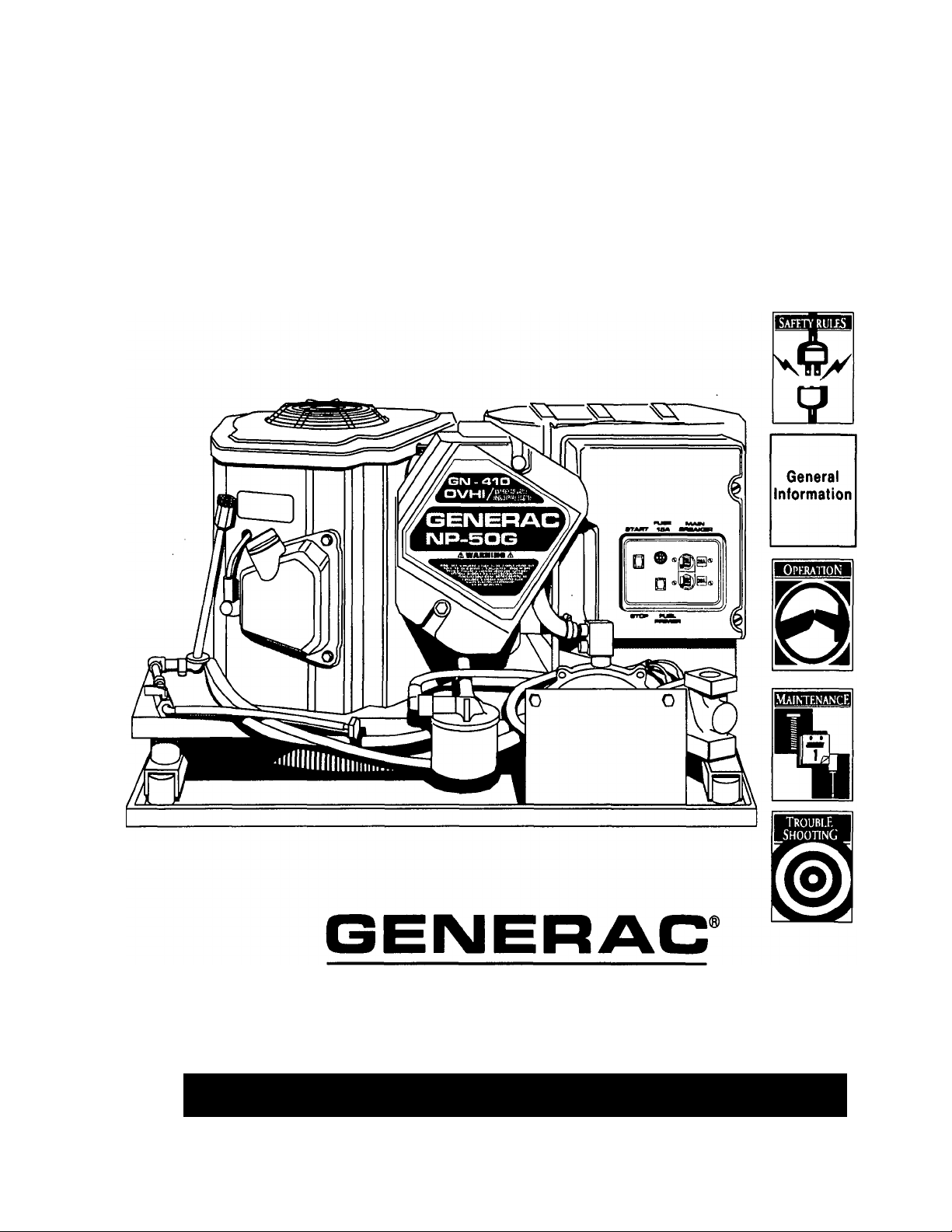
Air-cooled Recreational
Vehicle Generator
OWNER'S MANUAL
Manual No. A6451
THIS SYMBOL POINTS OUT IMPORTANT SAFETY INSTRUCTIONS, WHICH, IF NOT FOLLOWED. COULD ENDANGER THE
PERSONAL SAFETY AND OR PROPERTY OF YOURSELF AND OTHERS. READ AND FOLLOW ALL INSTRUCTIONS IN THE
MANUAL BEFORE ATTEMPTING TO OPERATE THIS UNIT,
Revision 0 (8/12/98)
POWER SYSTEMS
Model No. 00919-1 Series NP-50LPG
Printed in U.S.A.
Page 2

Generac NP-50LPG Recreational Vehicle Generator
THE MANUFACTURER SUGGESTS THAT THESE “RULES" FOR SAFE OPERATION BE COPIED AND POSTED IN
POTENTIAL HAZARD AREAS OF THE RECREATIONAL VEHICLE. SAFETY SHOULD BE STRESSED TO ALL
OPERATORS AND POTENTIAL OPERATORS OF THIS EQUIPMENT.
WARNING:
The engine exhaust from this product
contains chemicals known to the State
of California to cause cancer, birth
defects, or other reproductive harm.
Study these SAFETY RULES carefully before installing, operating or ser
vicing this equipment. Become familiar with the Owner's Manual and with
the generator. The generator can operate safely, efficiently and reliably only
if it is properly Installed, operated and maintained. Many accidents are
caused by failing to follow simple and fundamental rules or precautions.
Generac cannot possibly anticipate every possible circumstance that might
involve a hazard. The warnings in this Manual and on tags and decals affixed
to the unit, are therefore, not all-inclusive. If you use a procedure, work method
or operating technique Generac does not specifically recommend, you
must satisfy yourself that it is safe for you and others. You must also make
sure the procedure, work method or operating technique that you choose
does not render the generator to be unsafe.
• For fire safety, the generator must be installed and maintained properly.
Installation must always comply with applicable codes, standards, laws
and regulations. Adhere strictly to local, state and national electrical and
building codes. Comply with regulations the Occupational Safety and
Health Administration (OSHA) established. Also, the generator and
related components must be installed completely in conformance with
the manufacturer’s instructions and recommendations. Following proper
installation, do nothing that might alter a safe installation and render the
unit in non-compliance with such codes, standards, laws and regulations.
^ The Recreational Vehicle Generator produces extremely high and
dangerous electrical voltages and can cause dangerous, and possi
bly fatal, electrical shock. Avoid contact with bare wires, terminals, etc.
while the unit is running. If you must work around an operating gen
erator, stand on an insulated, dry surface to reduce shock hazard.
A Never work on this equipment or handle any electrical device while
standing in water, while barefoot, or while hands or feet are wet. Dan
gerous electrical shock will result.
• Have the generator properly grounded (bonded) during installation onto
the vehicle, either by solid mounting to the vehicle frame or chassis or
by means of an approved bonding conductor. DO NOT disconnect the
bonding conductor, if so equipped. DO NOT reconnect the bonding con
ductor to any generator part that might be removed or disassembled during
routine maintenance. If the grounding conductor must be replaced, use
only a flexible conductor that is of No. 8 AWG copper wire minimum.
• Keep hands, feet, clothing, etc., away from drive belts, fans and other
moving parts of this equipment. Never remove any drive belt or fan
guards while the unit is operating.
* •
• Inspect the generator periodically. Repair or replace all damaged or
defective parts immediately.
A
In case of accident caused by electric shock, shut down the source
of electrical power at once. If this cannot be done, free victim from live
conductor. AVOID DIRECT CONTACT WITH THE VICTIM. Use a dry
board, dry rope, or other non-conducting implement to free the victim
from live conductor. If victim is unconscious, apply first aid and get
medical help
• Inspect fuel system frequently for leaks or damage. Repair or replace
any damaged or leaking component immediately. Never attempt to
change, alter or modify the generator fuel system in any way that might
affect safety or compliance with applicable codes and standards.
The generator engine gives off DEADLY carbon monoxide gas through
its exhaust system. This dangerous gas, if breathed in sufficient con
centrations, can cause unconsciousness or even death. This exhaust
system must have been properly installed, in strict compiiance with
appiicable codes and standards. Following installation, you must do
nothing that might render the system unsafe or in non-compliance with
such codes and standards. The generator compartment must be com
pletely vapor sealed from vehicle interior. There must be no possibility
of exhaust fumes entering the vehicle interior. Never operate this
equipment with a leaking or defective exhaust system.
• Never use the generator or any of its parts as a step. Stepping on the
unit can stress and break parts and may result in dangerous operating
conditions from leaking exhaust gases, fuel leakage, oil leakage, etc.
• Do not smoke around the generator. Wipe up any fuel or oil spills imme
diately. Never leave oily or fuel soaked rags in the generator compartment
or on the generator itself. Keep the area around the generator clean and
free of debris.
• Adequate ventilation is required to expel toxic fumes and fuel vapors from
the generator compartment. Do not alter the installation of this equip
ment in any manner that might obstruct air and ventilation openings. Such
openings must be kept clear and unobstructed.
A Some generators may use LP gas (propane) as a fuel. LP gas is highly
EXPLOSIVE. The gas is heavier than air and tends to settle in low
areas where even the slightest spark can ignite the gas and cause an
explosion.
• Before performing any maintenance on the generator set, disconnect its
battery cables to prevent accidental start up. Disconnect the cable from
the battery post indicated by a NEGATIVE, NEG or (-) first. Reconnect
that cable last.
Recreational Vehicle Generator
Page 3
Generac NP-50LPG Recreational Vehicle Generator
IDENTIFI
CATION
RECORD
Please record the following information from the generator DATA DECAL or information decal.
1. Model Number
3. kW Rating.
_____________________
2. Serial Number
4. Rated Voltage.
____________________
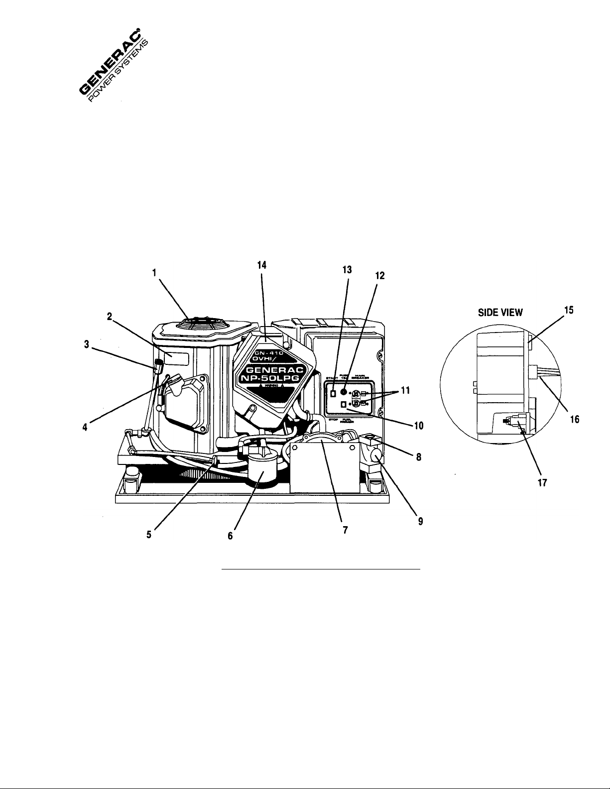
1. Generator Air Intake Screen
2. Data Decal
3. Oil Dipstick
4. Oil Filler Cap
5. Oil Drain Plug
6. Oil Filter
7. Fuel Regulator
8. Fuel Solenoid
9. Fuel Inlet
REFERENCE NUMBER IDENTIFICATION
10. Fuel Primer Switch
11. Circuit Breakers
12. Fuse
13. Engine Start/Stop Switch
14. Air Cleaner
15. Remote Panel Receptacle
16. Generator AC Output Leads
17. Starter Contactor
Recreational Vehicle Generator
3
Page 4

Generac NP-50LPG Recreational Vehicle Generator
SAFETY RULES.....................................inside front cover
IDENTIFICATION RECORD............................................3
GENERAL FEATURES....................................................3
READ THIS MANUAL
Read This Manual Thouroughly
...........................................
Operation and Maintenance................................................5
How to Obtain Service
........................................................
Service Dealer Location....................................................... 5
GENERATOR FAMILIARIZATION
Generator Applicability
.......................................................
Installation.........................................................................6
Safety
...............................................................................
Generator AC Connection System
........................................
OPERATION
Generator Control Panel
.....................................................
Optional Remote Start/Stop Panel....................................... 7
Before Starting the Engine...................................................8
Starting the Generator
Stopping the Generator
.....................................................
......................................................
8-9
Applying Loads to Generator...........................................9-10
Additional Information................................................ 10-11
MAINTENANCE
Checking Engine Oil Level.................................................. 13
Change Engine Oil............................................................ 13
Change Oil Filter
5
5
Engine Air Cleaner
Clean Air Intake Screen
Engine Spark Plug............................................................. 14
Spark Arrestor Muffler...................................................... 15
Cleaning the Generator
Battery
...........................................................................
6
Major Service Manual
..............................................................
............................................................
.....................................................
....................................................
......................................................
13
14
14
15
15
16
Drive Belt........................................................................ 16
6
6
Exercising the Generator................................................... 16
Out of Service Protection
..................................................
16
Return the Unit to Service after Storage.............................. 16
7
9
TROUBLESHOOTING................................................. 17
ELECTRICAL DATA
REPAIR PARTS
EMISSIONS WARRANTY
BASIC 3-YEAR WARRANTY
...
........................................... 18-19
.....................................................
.......................................
............................
back cover
20-29
30-31
SPECIFICATIONS
Fuel Requirements........................................................... 12
Fuel Consumption............................................................ 12
Engine Oil Requirements
..................................................
12
Engine Specifications........................................................ 12
Generator Specifications................................................... 12
Recreational Vehicle Generator
Page 5

read
THIS
MANUAL
Generac NP-50LPG Recreational Vehicle Generator
READ THIS MANUAL THOROUGHLY
If you don't understand any portion of this manual, contact Gen
erac for a demonstration of actual starting, operating and
servicing procedures.
Throughout this publication and on tags and decals affixed to
the generator, DANGER, WARNING and CAUTION blocks are
used to alert you to special instructtons about a particular oper
ation that may be hazardous if performed incorrectly or
carelessly. Observe them carefully.
These safety warnings cannot eliminate the hazards that they
indicate. Strict compliance with the special instructions while
performing the service plus "common sense" are major mea
sures to prevent accidents.
The following definitions apply to DANGER, WARNING, CAU
TION and NOTE blocks found throughout the manual.
DANGER: After this heading you can read handling,
instaliing, operating or servicing instructions that, if
not complied with, wiii resuit in personai injury.
WARNiNG; After this heading you can read handiing,
instaiiing, operating or servicing instructions that, if
not compiied with, may result in personal injury.
The operator (owner) is responsible for proper and safe use
of the vehicle, equipment on the vehicle, and the safety of
all vehicle occupants. We strongly recommend that the
operator read this Owner’s Manual and thoroughly under
stand all instructions before using this equipment. We also
strongly recommend instructing other occupants in the vehi
cle to properly start and operate the generator. This
prepares them if they need to operate the equipment in an
emergency.
OPERATION AND MAINTENANCE
It is the operator's responsibility to perform all safety checks;
to make sure that all maintenance for safe operation is per
formed promptly; and to have the equipment checked by an
Authorized Dealer periodically. Normal maintenance service
and replacement of parts are the responsibility of the
Owner/Operator and, as such, are not considered defects in
materials or workmanship within the terms of the warranty. Indi
vidual operating habits and usage contribute to the need for
maintenance service.
Proper maintenance and care of your recreational vehicle
generator assures a minimum number of problems and keeps
your operating expenses at a minimum. See your authorized
Dealer/Distributor for service aids and accessories.
CAUTION: After this heading you can read instruc
tions for handling, installing, operating or servicing
the generator that, if not strictly complied with, may
result in damage to equipment and/or property.
NOTE: After this heading you can read explanatory statements
that require special emphasis.
These symbols indicate the following:
Points out important safety information and, if not fol
lowed, could endanger personal safety and/or property
of yourself and others.
Potential explosion hazard.
Potential fire hazard.
Potential electrical shock hazard.
A
Recreational Vehicle Generator
HOW TO OBTAIN SERVICE
When your recreational vehicle generator requires servicing
or repairs, simply contact an Authorized Service Facility for
assistance. Service technicians are factory-trained and are
capable of handling all of your service needs.
When contacting an Authorized Service Facility or the factory
about parts and service, always supply the complete model
number and serial number of your unit as given on its data
decal.
The warranty on your generator is included in the Owner’s
Manual, as well as listings for repair parts.
SERVICE DEALER LOCATION
TO LOCATE THE NEAREST GENERAC SERVIC
ING DEALER, PLEASE CALL OUR 800 NUMBER.
ONLY DEALER LOCATION INFORMATION CAN BE
OBTAINED AT THIS NUMBER.
1-800-333-1322
Page 6
GENERAL
INFORMA
TION
Generac NP-50LPG Recreational Vehicle Generator
GENERATOR APPLICABILITY
These generators have been designed and manufactured for
supplying electrical power for recreational vehicles. You should
not modify the generator or use it for any application other than
for what it was designed. If there are any questions pertain
ing to its application, write or call the factory. Do not use the
unit until you have been advised by a competent authority.
DANGER: For fire safety, the generator must have
been properly installed in compliance with (1)
A
ANSI 119.2-1975/NFPA 501C-1974 “STANDARD
FOR RECREATIONAL VEHICLES, PART ill,
“INSTALLATION OF ELECTRICAL SYSTEMS.” The
generator must also have been installed in strict
compliance with the manufacturer’s detailed instal
lation instructions. After installation, do nothing
that might render the unit in non-compliance with
such codes, standards and instructions.
You can use this generator to supply electrical power for oper
ating 120/240 volts, single phase, 60 Hertz, AC electrical
loads. These loads can require up to 4500 watts of (4.5kW)
of power, but cannot exceed 37.5 AC amperes of current at
120 volts or exceed 18.8 AC amperes at 240 volts.
CAUTION: Do not overload the generator. Some
installations may require that electrical loads be
alternated to avoid overloading. Applying exces
sively high electrical loads may damage the
generator and may shorten its life. Add up the
rated watts of all electrical lighting, appliance, tool
and motor loads the generator will power at one
time. This total should not be greater than the
wattage capacity of the generator. If an electrical
device nameplate gives only volts and amps, multi
ply volts times amps to obtain watts (volts x amps
s watts). Some electric motors require more watts
of power (or amps of current) for starting than for
continuous operation.
Owners/Operators must make sure to do nothing that might
render the installation unsafe or in noncompliance with applic
able codes, standards and instructions. They should be sure
the unit has been installed to allow adequate ventilation for cool
ing and exhaust air.
SAFETY
Before attempting to use the generator set, carefully read
GENERAL SAFETY RULES inside the cover of this Manual.
Comply strictly virith these RULES to prevent accidents and
damage to equipment and/or property. We suggest that copy
ing and posting GENERAL SAFETY RULES in potential hazard
areas of the vehicle. Stress safety to all operators and poten
tial operators of this equipment.
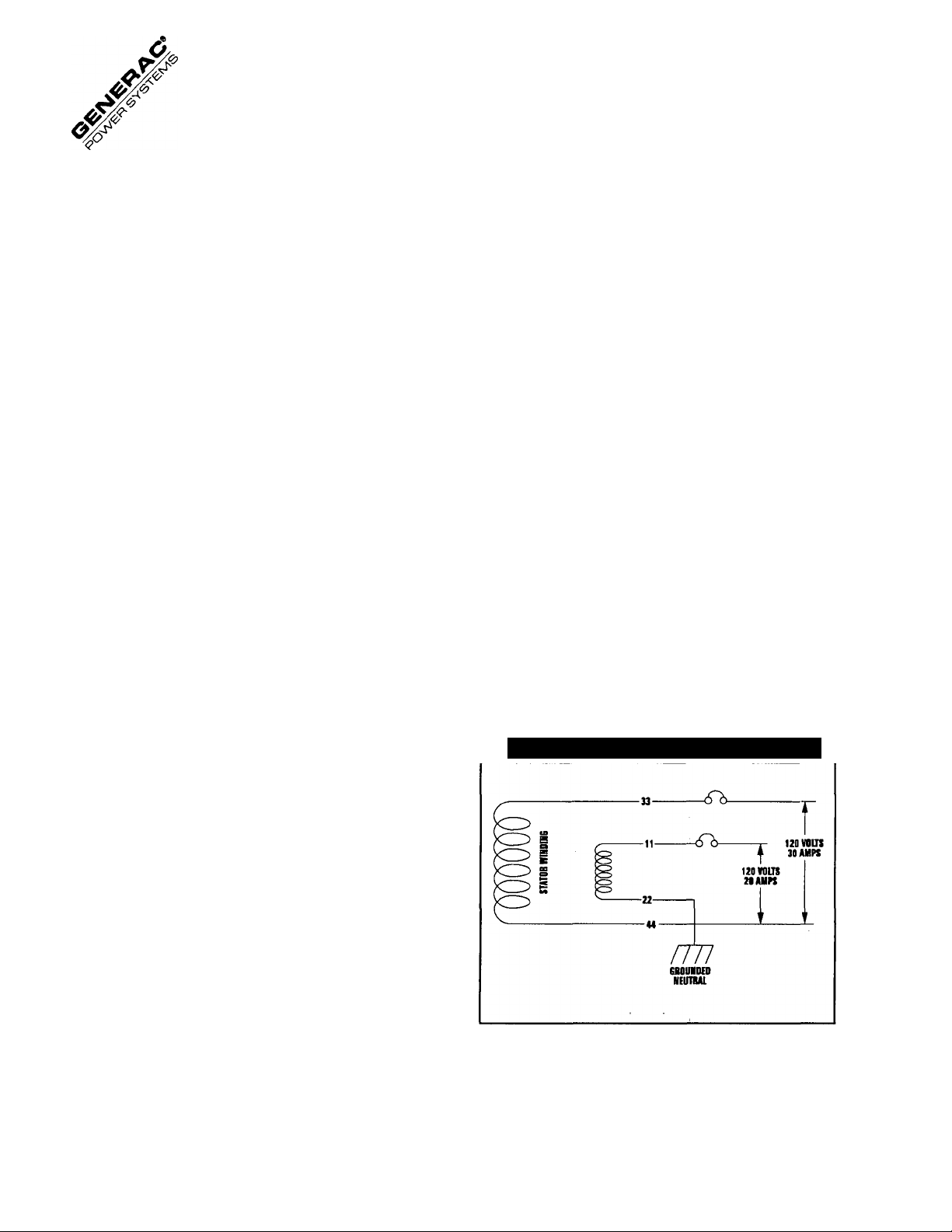
GENERATOR AC CONNEQION
SYSTEM
This generator set is equipped with dual stator AC power
windings. These two stator windings supply electrical power
to customer electrical loads by means of a dual 2-wire con
nection system. Note, however, that neutral is grounded.
The generator may have been installed so that the unit powers
120 volt AC loads (Figure 1); or you can wire them to connect
both 120 and/or 240 volt AC electrical loads. Be sure to install
jumper wire between the circuit breakers when reconnecting
for 120/240 volts. Refer to the Installation Manual for more
information.
Figure 1 — Connections for 120 Volts Only
INSTALLATION
This Owner’s Manual has been prepared under the assump
tion that a competent, qualified technician installed the
generator. We also assume the installer complied with all
applicable codes, standards and regulations pertaining to
installation.
Recreational Vehicle Generator
6
Page 7
Generac NP-50LPG Recreational Vehicle Generator
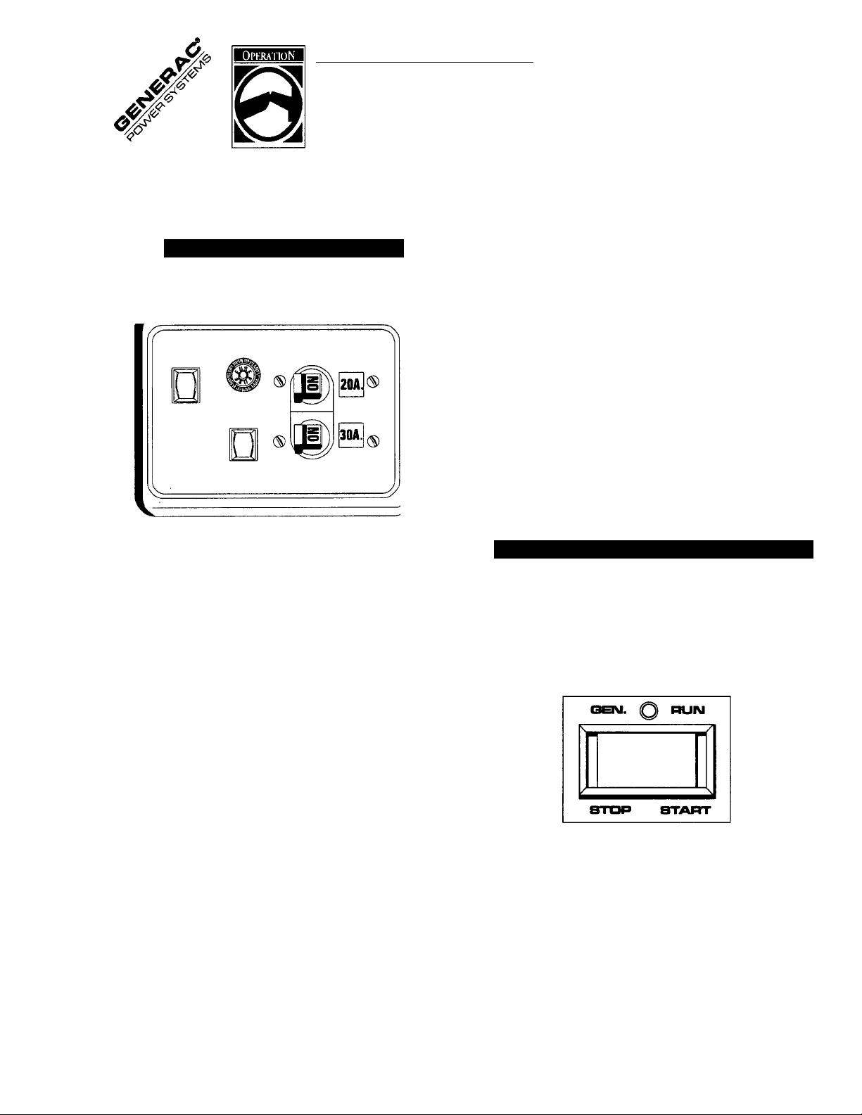
GENERATOR CONTROL PANEL
Mounted on the generator control panel (Figure 2) are the fol
lowing features;
Figure 2 — Generator Control Panel
FUSE MAIN
START nSA BREAKER
STOP FUEL
PRIMI
MAIN BREAKER
Protects generators AC output circuit against overload and pro
vides a method of turning OFF the generators 120/240 volts
AC output to vehicle circuits. The NP-50LPG has one 20 amp
breaker and one 30 amp breaker.
NOTE: If the Series NP-50LPG has been reconnected for dual
voltage AC output (120/240 volts), you can install line break
ers having an amperage rating that is different than stated
above. The replacement line breakers consist of two sepa
rate breakers with a connecting piece between the breaker
handles (so that both breakers will operate at the same time).
If the unit is reconnected for dual voltage, IT IS NO LONGER
RVIA LISTED.
OPTIONAL REMOTE
START/STOP PANEL
A remote mounted Start/Stop Panel is available, which allows
you to start and stop the generator engine conveniently from
inside the vehicle.
Figure 3 — Optional Remote Panel (Model 9042)
FUEL PRIMER
Before starting a cold engine (if it has not been started in more
than two weeks), you must press this switch for approximately
5 seconds to bring fuel from the tank to the fuel regulator. This
rocker type switch springs back into its original position when
you release it.
START/STOP SWITCH
To crank and start the engine, hold this switch at its START
position. Release the switch when the engine starts. To stop
an operating engine, press and hold the switch in its STOP
position until the engine shuts off. The switch center position
is the RUN position.
FUSE
Protects the engine DC control circuit against electrical over
load. If the fuse element has melted open due to overloading,
the engine cannot be cranked. If you must replace it, use only
an identical replacement fuse.
©
GEIMEI
R.V.
©
Recreational Vehicle Generator
7
Page 8

Generac NP-50LPG Recreational Vehicle Generator
BEFORE STARTING THE ENGINE
IMPORTANT: Instructions and information in this manual
assume the generator has been properly installed, connected,
serviced, tested and adjusted by a qualified installation tech
nician or installation contractor.
■ INSTALLATION_______________________________
Generator installation must have been properly completed so
it complies with all applicable codes, standards and regula
tions and with the manufacturer's recommendations.
■ ENGINE LUBRICATION
Have engine crankcase properly serviced with recommended
oil before starting. Refer to MAINTENANCE and SPECIFI
CATIONS sections for oil servicing procedures and
recommendations.
CAUTION: Any attempt to crank or start the engine
before you have properly serviced it with the recom
mended oii may resuit in an engine failure.
FUEL SUPPLY
The engine must have adequate supply of proper fuel to oper
ate. Before starting, check that sufficient fuel is available.
■ COOLING AND VENTILATING AIR
Air inlet and outlet openings in generator compartment must
be open and unobstructed for continued proper operation.
Without sufficient cooling and ventilating air flow, the enginegenerator quickly overheats which causes it to shutdown and
it could damage the generator.
■ ENGINE EXHAUST CAS
Before starting the generator engine, you should be sure there
is no way for exhaust gases to enter the vehicle interior and
endanger people or animals. Close windows, doors and other
openings in the vehicle that, if open, might permit exhaust gases
to enter the vehicle.
______________________
_____________________
DANGER; The generator engine gives off DEADLY
carbon monoxide gas through its exhaust system.
This dangerous gas, if breathed in sufficient con
centrations, can cause unconsciousness or even
death. DO NOT OPERATE THE GENERATOR IF
THE EXHAUST SYSTEM IS LEAKING OR HAS
BEEN DAMAGED. SYMPTOMS OF CARBON
MONOXIDE POISONING ARE (a) inability to think
coherently; (b) vomiting; (c) twitching muscles; (d)
throbbing temples; (e) dizziness; (f) headaches;
(g) weakness and sleepiness. IF YOU FEEL ANY
OF THESE SYMPTOMS, MOVE INTO FRESH AIR
IMMEDIATELY. IF SYMPTOMS PERSIST, GET MED
ICAL HELP.
STARTING THE GENERATOR
IMPORTANT: Read the vehicle manufacturer’s instructions.
The owner/operator should become familiar with the vehicle
in which the generator is installed. Differences exist between
vehicles. For example, some vehicles may use a transfer
switch to isolate dockside power from the generator, while other
vehicles may use an isolating receptacle. Some vehicles may
be equipped with a DC converter which allows the generator
to power certain DC lighting and other DC loads.
To start the generator from either the generator control panel
or from the optional Remote Panel, proceed as follows:
1. Turn OFF electrical loads, using whatever means provided
in your vehicle (such as a main line circuit breaker or trans
fer switch).
NOTE: If starting from the generator panel, turn OFF loads
by setting the generator's main circuit breaker to “OFF” or
“OPEN”. If starting from a Remote Panel, turn OFF loads using
whatever means is provided in the vehicle (such as a main cir
cuit breaker). Electrical load circuits will be turned ON after
the generator has started, stabilized and warmed up.
2. If you have not started the engine in more than two weeks,
press the Fuel Primer switch and hold it for about 30 seconds
to prime fuel system. However, if the engine is warm, skip Step
2.
Recreational Vehicle Generator
Page 9

Generac NP-50LPG Recreational Vehicle Generator
3. Hold the engine Start/Stop Switch at START to crank engine.
Release the switch when the engine starts.
CAUTION; If the engine does not start after it has
been cranking for 15 seconds, release the
Start/Stop switch and try again. Hoiding the switch
for longer than 15 seconds can damage the starter
motor.
4. Let the engine run at no-load tor a few minutes to stabilize
and warm up.
5. Turn ON electrical loads, using whatever means provided
(such as a main circuit breaker or transfer switch).
STOPPING THE GENERATOR
1. Turn OFF all electrical loads, using whatever means pro
vided (such as a main circuit breaker or transfer switch).
2. Let unit run a few minutes to stabilize temperature.
3. Hold the Start/Stop switch in its STOP position until engine
comes to a complete stop.
APPLYING LOADS TO GENERATOR
When applying electrical loads to the generator, observe these
guidelines;
Before applying electrical loads, let the generator stabilize
and warm up for a minute or two.
DO NOT overload the generator.
WAHAGE REFERENCE GUIDE
RUNNING
WATTS
‘Air Conditioner (12,000 Btu)
Battery Charger (20 amp)....................................................500
Belt Sander (3”)................................................................1000
Chain Saw
Circular Saw (6-12”)
Coffee Maker
‘Compressor (1 HP)
‘Deep Freeze..................................................................... 500
Disc Sander (9”)
Electric Range (one element).............................................1500
Electric Skillet...................................................................1250
‘Furnace Fan (1/3 HP)
Hair Dryer........................................................................1200
Hand Drill (Г)....................................................................1100
Hedge Trimmer
Impact Wrench..................................................................500
.......................................................................
................................................
..................................................................
..........................................................
...............................................................
.................................................................
.............................................
800 to 1000
.......................................................
Recreational Vehicle Generator
1700
1200
1000
2000
1200
1200
450
LET ENGINE STABILIZE
The generator supplies correct rated voltage only at proper
governed speed. Some electrical appliances may be extremely
sensitive to voltage. Incorrect voltages can damage those
appliances.
If electrical loads are applied at reduced operating speeds,
such loads imposed on the engine when sufficient power is not
available may shorten engine life. Never turn ON electrical
loads until after the generator engine has started and stabi
lized ON-speed.
■ DO NOT OVERLOAD THE GENERATOR
You can read the rated wattage/amperage capacity of your gen
erator on the generator data decal (see “Identification Record”
on Page 3).
Applying electrical loads in excess of the unit's rated capac
ity will cause the engine-generator to automatically shutdown.
To avoid overloading, add up the wattage of all connected elec
trical lighting, appliance, tool and motor loads. This total should
not be greater than the generator’s rated wattage capacity.
Most lighting, appliance, tool, and motor loads indicate their
required watts on their nameplate or data plate. For light
bulbs, simply note the wattage rating of the bulb.
If a load does not show its rated wattage, multiply that load’s
rated VOLTS times AMPS to obtain WATTS.
RUNNING
WAHS
Lawn Mower
Light Bulb
Microwave Oven................................................................700
‘Milk Cooler
Oil Burner on Furnace
Oil Fired Space Heater (140,000 Btu).....................................400
‘Paint Sprayer, Airless (1/3 HP)
Radio.........................................................................50 to 200
‘Refrigerator
Slow Cooker.......................................................................200
‘Submersible Pump (1-1/2 HP)
‘Submersible Pump (1 HP)
‘Table Saw (10”)..........................................
Television.............................................................1750 to 2000
...................................................................
..........................................................................
.....................................................................
.........................................................
.............................................
......................................................................
...........................................
.................................................
..........
‘ Allow 2-1/2 times the listed watts for starting these devices.
1200
100
1100
300
600
600
2800
2000
1750 to 2000
Page 10
Generac NP-50LPG Recreational Vehicle Generator
Induction type motors (such as those that run the vehicle's
furnace fan, refrigerator, air conditioner, etc.) need about 21/2 time more watts of power for starting than for running
(for a few seconds during motor starting). Be sure to allow
for this when connecting electrical loads to the generator.
First, figure the watts needed to start electric motors in the
system. To that figure, add the running wattages of other
items that will be operated by the generator.
Do not apply heavy electrical loads for the first two or three
hours of operation.
ADDITIONAL INFORMATION
This section discusses some the the engine protective devices,
overload protection and breaking in a new generator.
■ AUTOMATIC LOW OIL PRESSURE
SHUTDOWN__________________________________
The engine is equipped with a normally-closed (N.C.) oil pres
sure switch (Figure 4). Engine oil pressure holds the switch
open during cranking and operation. Should oil pressure drop
below a pre-set level, the switch contacts close and the engine
automatically shuts down.
■ HIGH TEMPERATURE SHUTDOWN
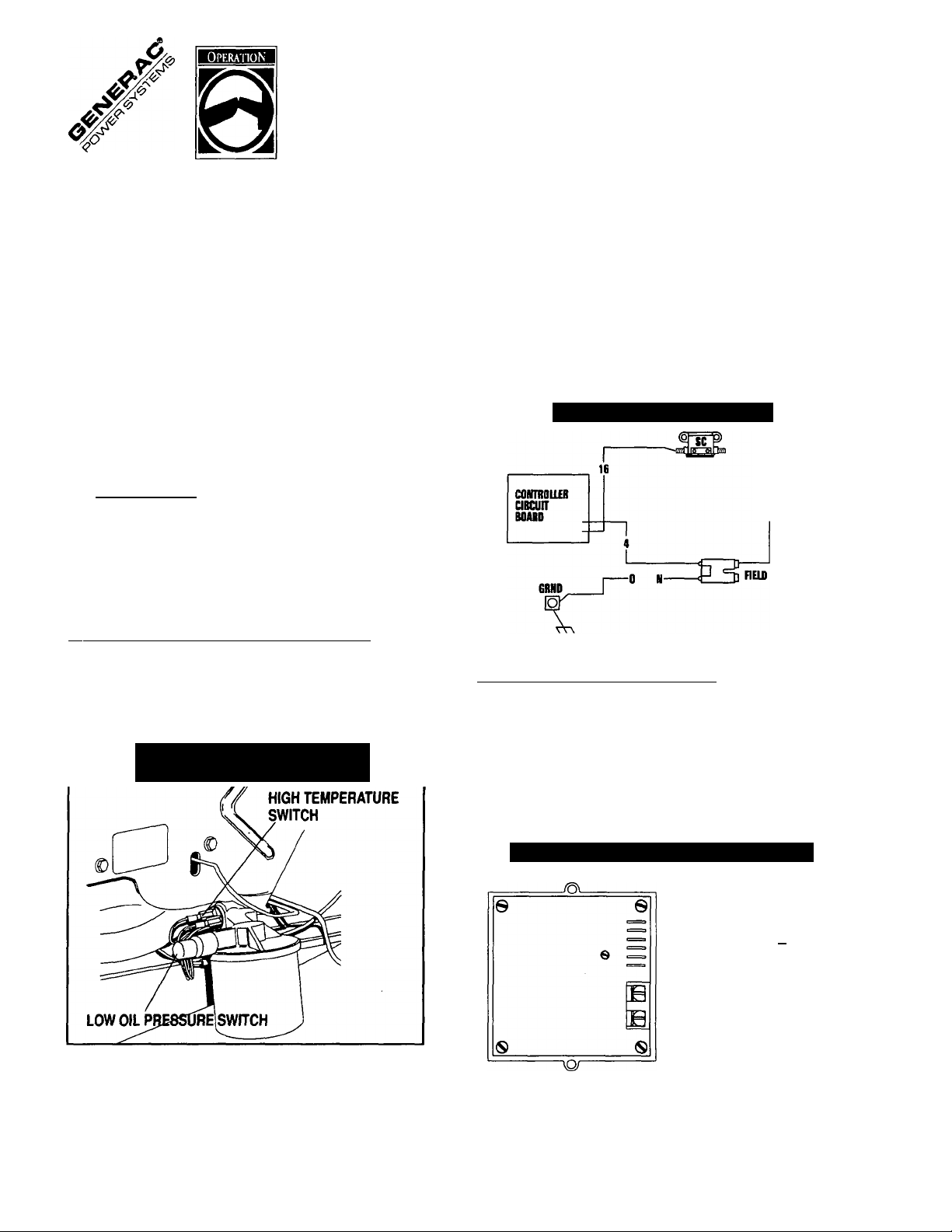
FIELD BOOST
The Controller Circuit Board houses a field boost diode and
resistor which are part of a lield boost” circuit (Figure 5).
During engine cranking only, a positive DC (battery) voltage
is delivered through the diode, resistor, brushes and slip rings,
and the generator rotor. Application of this voltage to the
rotor Hashes the field" whenever it is started. Flashing of the
field each time the generator starts makes sure that a suffi
ciently strong magnetic field is available to produce "pick-up"
voltage in the stator windings.
Figure 5 — Field Boost Circuit
CLOSEST TO
BEADING
A temperature switch (Figure 4) with normally-open (N.O.) con
tacts is mounted near the oil filter. If engine temperature were
to exceed about 284°F (140°C), the switch contacts close
and the engine shuts down.
Figure 4 — Switches for Engine
Safety Shutdown
■ OVERVOLTAGE PROTEaiON
A solid state voltage regulator (Figure 6) controls the gener
ator's AC output voltage. This regulator supplies an excitation
current to the rotor. By regulating the rotor's excitation cur
rent, the strength of its magnetic field is regulated and, in
turn, the voltage delivered to connected electrical loads is
controlled. When the AC frequency is 60 Hz, voltage is reg
ulated at 120 volts (voltage-to-frequency ratio is 2-to-1).
Figure 6 — Solid State Voltage Regulator
i^'ZhsasiNs
-4(+)t_tb Bonn
CORROn)
jsnmii
EXOTATimiraBniB
(AUniUTUIG cmun)
Recreational Vehicle Generator
10
Page 11

Generac NP-50LPG Recreational Vehicle Generator
The voltage regulator also incorporates a “voltage surge pro
tection circuit.” This circuit prevents troublesome surges in the
generator AC output voltage. Voltage surge is a common cause
of damage to electronic equipment.
■ 25-HOUR BREAK IN PERIOD
The first 25 hours of operation is the break-in period for the
generator. Properly breaking in the generator is essential to
minimize fuel consumption and provide maximum engine per
formance. During this 25-hour break in period, follow this
procedure:
• Run the unit at varying electrical loads, to help seat engine
piston rings properly.
• For the 75-hour operation following the break in period,
avoid light electrical loads. Load the generator at 50% (or
more) of its rated wattage capacity. Repeated light loads
during these 75 hours can cause improper seating of engine
piston rings, resulting in blowby and high oil consumption.
• Check engine oil level frequently. Add oil if needed. It is
normal for the generator engine to consume more oil than
is normal until the piston rings have properly seated.
• After operating the unit for 25 hours, complete the tasks rec
ommended under “25-Hour Check Up.”
■ 25-HOUR CHECK UP
After the 25-hour break-in period, contact an authorized ser
vice facility for the following maintenance. The vehicle owner
is responsible for any charges:
• Change engine crankcase oil and oil filter.
Check oil level.
• Inspect cooling and ventilation openings.
Check engine carburetor.
• Check engine ignition system.
• Inspect entire electrical system.
• Inspect the engine exhaust system.
________________________
________________
■ AHENTION REQUIRED AFTER
SUBMERSION
If the recreational vehicle generator has been submerged in
water, it must NOT be started or operated. Following any sub
mersion in water, have an authorized Generac Service Facility
thoroughly clean and dry the generator.
■ OPERATING PRECAUTIONS
Never operate the generator set while the vehicle is parked
over dry leaves, dry grass or any other combustible substance.
The generator’s exhaust system becomes extremely hot and
can cause fire if it is too close to combustible materials.
The generator’s exhaust system gives off DEADLY carbon
monoxide gas. this dangerous gas, if breathed in sufficient
concentrations, can cause unconsciousness and even death,
never operate the generator set with the vehicle inside any
garage or enclosed area. Never operate the generator if it has
a leaky exhaust system. Close windows in the vicinity of the
generator exhaust outlet and take any other steps to prevent
exhaust gases from entering rooms or areas occupied by
people or animals.
________________________________
_________________
■ EFFECTS OF MOISTURE AND DIRT
Keep the generator set as clean and dry as possible. Protect
the unit against excessive dust, dirt, corrosive vapors, road
splash, etc. Permitting dirt and moisture to accumulate on
generator windings will have an adverse effect on the insula
tion resistance of those windings.
When moisture is allowed to remain in contact with windings,
some of the moisture will be retained in voids and cracks in the
insulation. This causes a reduced insulation resistance and
will eventually cause problems. Dirt will make the problem
worse, since dirt tends to hold moisture in contact with wind
ings. Salt (as from sea air) will also worsen the problem since
it tends to absorb moisture from the air. Salt and moisture,
when combined, form a good electrical conductor.
■ OPERATION IN HIGH GRASS
OR BRUSH
WARNING; Never operate the generator while the
vehicle is parked in high grass, weeds, brush or
A
leaves. Such materials can ignite and burn from
the heat of the exhaust system. The generator
exhaust becomes extremely hot during operation
and remains hot for a long t
Recreational Vehicle Generator
11
Page 12

Generac NP-50LPG Recreational Vehicle Generator
FUEL REQUIREMENTS
The “NP” series generator is equipped with a liquefied petro
leum (LP) gas fuel system. LP gas is usually supplied as a
liquid in pressure tanks.
“NP” series generators require a “vapor withdrawal" type fuel
system. This type of gaseous fuel system uses the vapors
forming above the liquid fuel in the storage tank. Air temper
ature around the storage tank must be high enough to sustain
adequate fuel vaporization. In colder climates, you may need
to use an independent heat source to be sure the fuel suffi
ciently vaporizes in the storage tank.
LP gas may consist of propane, butane or a mixture of two
gases. Using fresh HD-5 LP is recommended. Fuel should
not contain more than 2.5% butane. Propane vaporizes at tem
peratures as low as -20°F (-29°C), but butane returns to its
liquid state when the temperature drops below about 32°F
(0°C). For that reason, a higher ratio of propane is desired in
the gas mixture when temperatures drop below freezing.
FUEL CONSUMPTION
(CUBIC FEET PER HOUR)
The following lists the approximate amount of fuel the unit con
sumes at 100% rated load. Actual fuel consumption may
vary depending on BTU content of fuel, applied load, ambi
ent conditions, engine condition, etc.
Propane
................................................
47 cubic ft. per hour
ENGINE OIL REQUIREMENTS
Use only high quality detergent oil rated with API ser
vice classification SR SG or SH. The recommended oil
weights include the following:
• During summer months: SAE 30. An acceptable substitute
isSAE10W-30.
• During winter months: SAE 5W30. DO NOT USE SAE
10W-40.
Crankcase and oil filter capacity is about 1400ml or
about 1.5 U.S. quart. Use no special additives. See
“Maintenance” section for oil level check and fill proce
dures.
SPECIFICATIONS
■ ENGINE_______________________________________
Type of Engine
Cooling Method.......................................................................Air-cooled
Rated Horsepower
Displacement..................................................................................407cc
Cylinder Block..........................................Aluminum with cast iron sleeve
Type of Governor
Air Cleaner
Starter.........................................................................12 volt DC electric
Ignition System.................................................................................. Solid State
Recommended Spark Plugs
Champion...............................................................................RC12YC
AC..............................................................................................R45S
Autolite.......................................................................................... 65
Spark Plug Gap
Recommended Battery........................................................................ 400 CCA
■ GENERATOR__________________________________
Rotor RPM.................................................................................... 3600
Rotor Poles.......................................................................................... 2
Engine RPM.................................................................................. 2571
Rated Maximum Continuous
AC Output
Voltage.................................................................................... 120 volts*
Rated Maximum Continuous AC Current................................37.5 amperes
Phase........................................................................................... single
Frequency................................................................................ 60 Hertz
Battery Charge Voltage.......................................................................... 14 VDC
Battery Charge Current...............................
Weight....................................................................197 pounds (93 kg)
Length....................................................................25 inches (635mm)
Width....................................................................18.5 inches (470mm)
Height
* The unit is reconnectable to 120 and/or 240 volts, dual voltage output.
Rated maximum continuous current at 240 volts is 18.8 amps.
....................................................
..............
................................................
......................................
.........................................................
...............................................................
....................................................
...........................................
Paper element with foam pre-cleaner
15.75inches(400mm)
GN-410, single-cylinder
Mechanical, fixed speed
0.030 inch (0.76mm)
4500 watts (4.5 kW)
..........................
15 at 4200 RPM
2 Amps Max.
Recreational Vehicle Generator
12
Page 13

Generac NP-50LPG Recreational Vehicle Generator
This section includes information about simple maintenance
which includes the following tasks.
• Checking engine oil level
• Changing engine oil
• Changing oil filter
• Clean or change the air cleaner
• Cleaning the air intake screen
• Cleaning spark plug
CHECKING ENGINE OIL LEVEL
Check engine crankcase oil level at least every eight hours of
operation, or before you use it.
Be sure the generator is as level as possible.
• Remove OIL DIPSTICK (Figure 7) and wipe it dry with clean,
lint-free cloth.
• Install and tighten oil dipstick then remove again.
• Oil level should be at the dipstick “FULL” mark. If necessary,
add oil to the “FULL” mark only. DO NOT FILL ABOVE THE
“FULL” MARK.
• Install and tighten oil dipstick before operating the engine.
NOTE: See “Engine Oil Requirements” on Page 12 for rec
ommended oils.
Figure 7 —Oil Dipstick and Oil Fill Cap
With engine still warm, remove oil drain cap from oil drain
hose (Figure 8). Drain oil completely into a suitable con
tainer.
Figure 8 — Location of Oil Drain Cap
• When oil has drained, install and tighten oil drain cap.
• Remove oil fill cap and fill crankcase with the recommended
oil (see Page 12). The engine crankcase can hold about 1.4
liters. DO NOT FILL ABOVE “FULL" MARK.
• Install and tighten oil dipstick and oil fill cap before operat
ing engine.
CHANGE OIL FILTER
Change engine oil filter after the first 25 hours of operation,
every 100 operating hours thereafter.
• Turn oil filter counterclockwise to remove (Figure 9).
• Coat gasket of new filter with engine oil.
• Turn new filter clockwise until its gasket contacts lightly with
the filter adapter. Then tighten with an additional 3/4 to one
turn by hand.
• Run engine and check for leaks.
NOTE: Check oil level and fill to full mark after checking for
leaks. Filter will retain some oil.
CHANGE ENGINE OIL
Change engine oil after the first 25 hours of operation (after
the 25-hour break-in period. Page 11). Thereafter, change oil
every 50 operating hours. Change oil more frequently if oper
ating consistently under heavy load or at high ambient
temperatures. To change oil, proceed as follows;
• Run engine for at least 5 minutes, then shut down.
Recreational Vehicle Generator
Figure 9 — Engine Oil Filter
13
Page 14

Generac NP-50LPG Recreational Vehicle Generator
ENGINE AIR CLEANER
Clean and re-oil the foam pre-cleaner every three months or
every 25 operating hours, \«hichever comes first. Service
more frequently if operating under extremely dusty or dirty con
ditions (Figure 10):
Remove both screws to loosen cover.
Remove the COVER, FOAM PRE-CLEANER and PAPER
FILTER.
Remove foam pre-cleaner from cover.
Wash foam pre-cleaner in liquid detergent and water.
Wrap foam pre-cleaner in a cloth and squeeze dry.
Saturate foam pre-cleaner in engine oil. Squeeze to remove
excess oil (Do not twist foam pre-cleaner).
Install foam pre-cleaner into cover, followed by paper filter.
Install cover, foam pre-cleaner and paper filter.
Tighten both screws to retain.
Once each year or every 100 hours of operation (whichever
comes first), replace the paper filter. The new replacement
filter must be a flame retardant type.
Figure 10 — Engine Air Cleaner
Clean air cleaner cover then insert pre-cleaner into cover.
Next insert new paper filter into cover to hold pre-cleaner
in place and assemble all of them to the base of the air
cleaner.
CLEAN AIR INTAKE SCREEN
Clean all foreign material from air intake screen (Figure 11)
at least once every 100 hours of operation. Clean more often
if necessary.
Inspect the area around the generator exhaust muffler peri
odically and remove all grass leaves, dirt, etc.from this area.
Figure 11 — Cleaning Air Intake Screen
■ CLEAN OR REPLACE AIR FILTER
Remove air cleaner cover; then remove foam pre-cleaner
(service if necessary) and remove paper filter.
Clean air filter by tapping it gently on a solid surface. If the
filter is too dirty, replace it with a new one. Dispose of the
old filter properly.
Recreational Vehicle Generator
ENGINE SPARK PLUG
Clean engine spark plug and set gap to 0.030 inch (0.76mm)
every 100 hours of operation (Figure 12). Clean by scraping
or wire brushing and washing with commercial solvent. DO
NOT BLAST CLEAN SPARK PLUG.
CAUTION: Sparking can occur if wire terminal
does not fit firmly on spark plug terminal end. If
necessary, reform wire terminal to obtain a tight fit.
Figure 12 — Setting Spark Plug Gap
14
Page 15

Generac NP-50LPG Recreational Vehicle Generator
SPARK ARRESTOR MUFFLER
If the generator is not equipped with a spark arrestor exhaust
muffler and is to be used on any forest covered, brush cov
ered or grass covered unimproved land, you may have to
install a spark arrestor. The spark arrestor must be maintained
in effective working order by the vehicle owner/operator.
For assistance in ordering, installing and maintaining spark
arrestor exhaust mufflers, contact your nearest authorized
service facility.
Exhaust mufflers supplied by Generac are spark arrestor
types. Generac exhaust muffler for recreational vehicle gen
erators do not have a spark arrestor screen, but are of the more
efficient “toroid" or “swirl” type. To remove carbon and com
bustion deposits from such mufflers, remove the PLUG from
the muffler and run engine for about 15 minutes. Shut engine
down, let the muffler cool and install the plug.
WARNING; Be sure to re-install the plug from the
muffler tightly. Engine vibration could cause a loose
A
plug to fall out. Without the plug in place, hot
engine exhaust is directed out the opening. This hot
exhaust, depending on the installation, could be
directed to areas not able to withstand the extreme
heat such as wooden floor boards or other flamma
ble material. This could result in a fire.
BAHERY
All lead-acid storage batteries will discharge when not in use.
The generator battery should be inspected as follows:
■ ONCE WEEKLY
Inspect battery posts and cables for tightness, corrosion.
Clean and/or tighten as needed.
Also check battery fluid level, and, if necessary, fill with DIS
TILLED WATER ONLY. DO NOT USE TAP WATER IN
BAHERY.
■ EVERY SIX MONTHS
Have battery state of charge and condition checked. This
should be done with an automotive type battery hydrometer.
DANGER: Storage batteries give off explosive
hydrogen gas. This gas can form an expiosive mix
A
ture around the battery for severai hours after
charging. The slightest spark can ignite the gas
and cause an explosion. Such an explosion can
shatter the battery and cause blindness or other
injury. Any area that houses a storage battery
must be properly ventilated. Do not allow smoking,
open flame, sparks or any spark producing tools
or equipment near the battery.
___________________
_________________________
___
CLEANING THE GENERATOR
Keep your generator set as clean and dry as possible. Dirt
and moisture that are permitted to accumuiate on electrical
windings have an adverse affect on the insulation resistance
of those windings.
Moisture that is allowed to remain in contact with windings will
be retained in voids and cracks of the windings. Dirt makes
the problem worse, since it tends to hold the moisture into con
tact with the windings. Salt, as from sea air, worsens the
problem since it tends to absorb moisture from the air. The
combination of salt and moisture makes a good electrical con
ductor.
CAUTION! Do NOT use a forceful spray of water to
clean the generator. Water will enter the generator
interior and cause problems, and may also conta
minate the generator fuel system.
Recreational Vehicle Generator
DANGER; Battery electrolyte fluid is an extremely
caustic sulfuric acid solution that can cause
severe bums. Do not permit fluid to contact eyes,
skin, clothing, painted surfaces, etc. Wear protec
tive goggles, protective clothing and gloves when
handling a battery. If you spill the fluid, flush the
affected area immediately with clear water.
DANGER; Do not use any jumper cables or
booster battery to crank and start the generator
engine. If any battery has discharged, remove it
from the vehicle for recharging.
15
Page 16

Generac NP-50LPG Recreational Vehicle Generator
MAJOR SERVICE MANUAL
To obtain a service manual for your generator, order it from
your dealer/distributor or contact the factory. Be sure to iden
tify your MODEL NUMBER and SERIAL NUMBER.
DRIVE BELT
The engine drives the generator rotor by means of a pulley
and drive belt arrangement. The drive belt and pulleys are war
ranted for the life of the generator. Drive belt tension was
properly adjusted before the unit was shipped from the fac
tory. If you suspect that drive belt tension is incorrect, contact
an authorized service facility.
EXERCISING THE GENERATOR
Generac recommends that you start and operate the genera
tor at least once every seven days. Let the unit run for at least
30 minutes to “exercise” the engine.
OUT OF SERVICE PROTEQION
If you cannot exercise the generator every seven days and it
is to be out of service longer than 30 days, prepare the gen
erator for storage as follows:
• Start the engine and let it warm up.
• Close the fuel shutoff valve in the fuel supply line and let
the engine “run out of fuel.”
• While the engine is still warm from running, drain the oil com
pletely. Refill crankcase with SAE 10W30 oil having API
classification “For Service SF.”
• Attach a tag to the engine indicating the viscosity and clas
sification of the oil in the crankcase.
• Remove spark plug and pour about two or three table
spoons of clean, fresh engine oil into spark plug threaded
opening. Crank engine several times to distribute oil, then
install and tighten spark plug.
• Remove the battery and store in a cool, dry room on a
wooden board. Never store the battery on concrete or earth
floors.
• Clean and wipe the entire generator.
RETURN THE UNIT TO SERVICE
AFTER STORAGE
To return the unit to service after storage, proceed as follows:
• Check tag on engine for oil viscosity and classification.
Verify that the correct recommended oil is used in engine.
If necessary, drain and refill with proper oii.
• Check battery. Fill all cells to thé proper level with distilled
water. DO NOT USE TAP WATER IN THE BAHERY.
Recharge battery to 100% state of charge, or, if defective,
replace the battery^
• Turn OFF all electrical loads, add fuel if necessary, then start
the engine.
• Let the engine warm up.
• Apply electrical loads to at least 50% of the unit’s rated
wattage capacity.
• When engine is thoroughly warmed up, shut it down.
THE GENERATOR IS NOW READY FOR SERVICE.
Recreational Vehicle Generator
16
Page 17

Generac NP-50LPG Recreational Vehicle Generator
TROUBLESHOOTING POINTS
PROBLEM
Engine won't crank.
Engine cranks but won't start 1. Out of fuel
Engine starts hard, runs rough.
GVUSE
1. 15 amp fuse blown. 1.
2. Loose, corroded or defective
battery cables
3. Battery is discharged or defective. 3.
4. Defective starter contactor. 4.
5. Defective starter motor.
6. Defective Controller circuit board ,
2. Fuel shutoff valve is closed.
3. Defective Controller circuit board 3. Replace if defective.
4. Spark plug defective.
5. Defective ignition coil on engine
6. Defective carburetor
7. Dirty air cleaner. 7.
8. Fuel solenoid is defective. 8. Replace or repair.
1. Dirty air cleaner. 1.
2. Defective spark plug.
3. Defective ignition coil. 3. Replace if defective.
CORREQION
Replace fuse.
2.
Tighten, clean or replace
as necessary.
Recharge or replace battery.
Replace if defective.
5
Replace if defective.
6. Replace if defective.
1.
Replenish fuel.
2.
Open fuel shutoff valve.
4.
Clean, regap or replace plug.
5. Replace if defective.
6.
Replace if defective.
Clean or replace elements as
needed.
Clean or replace elements as
needed.
2.
Clean, regap or replace plug.
Engine starts, shuts down when
Start/Stop switch is released. 2. Engine is overheated.
No AC output from generator.
1. Engine oil level is low.
3. Defective Low Oil Pressure Switch 3. Replace defective switch.
4. Defective Controller circuit board.
1. Check main line circuit breaker. 1.
2. Transfer switch (if so equipped) is set 2. Reset transfer switch.
to wrong position.
3. Failure in vehicle electrical system. 3. See vehicle manual.
4. Generator component failure. 4.
Recreational Vehicle Generator
17
1.
Check oil and add oil as needed.
2.
Check cooling system for blockage.
4.
Replace defective board.
Reset to ON or CLOSED.
Contact an authorized service
facility.
Page 18

Generac NP-50LPG Recreational Vehicle Generator
ELECTRICAL DATA Drawing No. 94210
BATTERY
-NEUTRAL CDNNECTION
BY CUSTOMER
BCR - BATTERY CHARGE RECTIFIER
CBl - CIRCUIT BREAKER. 30A
CB2 - CIRCUIT BREAKER. 20A
CB3 - CIRCUIT BREAKER. 2.5A
- CHOKE HEATER (GASOLINE MODELS ONLY)
- CHOKE SOLENOID (GASOLINE MODELS QNL'O
- FUSE, 15A
- FUEL PUMP-DR-LPG SHUT OFF VALVE
- TERMINAL, GROUND 4-TAB
- ^€TER. HOUR (OPTIONAL)
- SWITCH. HIGH TEMP. OIL (CLOSES ON HIGH TEMP.)
- IGNITION MAGNETO
- LIGHT. RUN (OPTIONAL)
- SWITCH, LOW OIL PRESSURE (CLOSES ON LOW PRESSURE)
PCB - ENGINE CONTROLLER
R1 - RESISTOR, 1 OHM 25W
STARTER CONTACTOR
STARTER MOTOR
SWITCH. START/STOP
SWITCH FUEL PRIMER
SPARK PLUG »1 CYL.
TERMINAL, CONN. 4-TAB
CONNECTOR
Recreational Vehicle Generator
18
LEGEND
Page 19

Generac NP-50LPG Recreational Vehicle Generator
ELECTRICAL DATA
Drawing No. 94210
Recreational Vehicle Generator
19
Page 20

Generac NP-50LPG Recreational Vehicle Generator
rJ’ -------------------------------------------------------
EXPLODED VIEW - BASE AND PULLEYS
Drawing No. 95865
Recreational Vehicle Generator
20
Page 21

Generac NP-50LPG Recreational Vehicle Generator
REPAIR PARTS - BASE AND PULLEYS
ITEM DESCRIPTION PART NO. QTY. ITEM
1 BASE, MOUNTING
GROUND CABLE 90141
2
3 MOUNT, (RUBBER) 46911 4
4
CAPSCREW, .-3/8"-16 X 1/2“
5 LOCKWASHER-M10 46526
6 LOCKWASHER-M8
7 SKID, RUBBER MOUNT
8 SAFEW BOLT 5/16"-18x 3 1/2" 77603 2
9 NUT, HEX-5/16-18
10 NUT, FLANGED LOCK-M8-1.25
11 CAPSCR. -M8-1.25X60MM
12 SPRING, BELT TENSION
13
14 SLIDE (NYLON)
15 SUPPORT, NYLON SLIDE
16
17 GASKET, EXHAUST MANIFOLD 90239 1
18 CAPSCR.,-M8-1.25x65 LG.
19 GASKET, COLLECTOR PAN
20
21 PULLEY, ENGINE
22 PULLEY, ALT.
23 BELT (POLY V 4D-40"
24 WASHER, PULLEY RETAINER
25 CAPSCR., HEX HD. 3/8“-24 x 1"
26 GUIDE, BLOWER HOUSING 77017 1
27 CAPSCR., 3/8"-24x2"
28 SCREW aAPTlTE)-M6-1.00 x 20 74906
30 HOUSING, BLOWER
31 SPACER, BLOWER HOUSING
32 LOCKWASHER, M5 22152
33 CAPSCR. -M5-0.80 x 80MM 77682
34
WASHER, SPRING CNTR.
MANIFOLD, EXHAUST
COVER PLATE -EXTERNAL
SPRING, GENERATOR SET MT 75242
92603
25017
22129
72391 2
22259 2 47
52858
51730
29459 2
75215 2
73146 4 52
75209 2 53 LOCKWASHER, SHAKEPR.-M6
91032 1 57
57636 2 59
92645
90859 1 61
75224-B 1 62
73106-B 1
75216
49451 1
42633
A8250
72375
73185 1 71
1
1
8
10 43 GASKET, EXH. PIPE
4
6 48 SCREW(CRIMPTITE) #10-24 x .5
2
1
1
1
1
2 69 90 "STREET ELBOW-3/4"
1
1 72
1
4
35 COVER PLATE, EXH. BASE
36 ADAPTOR, UNIVERSAL EXH.
41
42
44 FOAM TÁPE
45
46
49
50 PAN, SLIDE
51
58 DECAL, GROUND
60 SCREW, TAPTITE M6-1.0x10
63
64
65 45° STREET ELBOW-3/4"
66
67
68 FUEL HOSE-1/2" DIA. x 8.50"
70
73 M6 HEX NUT
76 M6x 16 HEX HD. CAPSCR.
Drawing No. 95865
DESCRIPTION
CLAMP, EXH. PIPE-1-1/4 DIA.
HHCS & LOCK WASH-M6-1DX16,
LUG, GROUNDING 62684
WASHER, SPRING RETAINER
COVER, AIR OPENING
GASKET, FOAM-SLIDE PAN
FLAT WASHER-M6
COVER, EXHAUST OUTLET
NUT, FLANGE-5/16-18 (SPECIAL) 81105
SCREW, TAPTITE M5-0.8 x 10.
FLAT WASHER-M10
REGULATOR MOUNT .BRACK.
REGULATOR 75211
FUEL SOLENOID 12VDC
STRAIGHT BARB. FIT.-1/2 x 3/8"
HOSE CLAMP-SIZE-#8 57822
PIPE, NIPPLE-3/4" x3" LG
M6-1.0x30 CAP SCREW
M6 LOCKWASHER
PART NO.
92203 1
91146 1
96289
,79246
77643
29289 10FT.
75237
75226 1
56893
75229 1
75227
22473 4
72384-C 1
22447
67210A 1
74908
45756
22131 1
78864
A2666 1
25425 1
63463 1
74994
26307
26881
38750
22097 4
49813 4
47411
QTY.
1
8
2
1
4
12
1
2
2
9
5
1
1
1
1
3
1
2
2
Recreational Vehicle Generator
21
Page 22

EXPLODED VIEW - ALTERNATOR AND PANEL
Drawing No. 94106
Recreational Vehicle Generator
22
Page 23

Generac NP-50LPG Recreational Vehicle Generator
REPAIR PARTS - ALTERNATOR AND PANEL
ITEM
14
15
16
17 Ground Cable
18
19
20
21
22
23
24
25
26
27 Remote Harness
28
29
30
31
32
33
34 Panel Support Bracket
35
DESCRIPTION
1 Lower Bearing Carrier 75995 1
50 Rotor Assembly 92605H 1 37 M6-1.0 Hex Nut
2
50 Stator Assembly 92604H 1
3
Ball Bearing
4
Ball Bearing 31971
5
Upper Bearing Carrier 72379B 1 41
6
Stator Stud
7
M8-1.25 Flange Lock Nut 52858
8
Brush Holder 66386
9
M 5-0.8 X 16 Taptite 66849
10
Nylon Washer 27756 4 46 20A. Circuit Breaker 90144
11
Generator Top Housing
12
Resistor 75234
13
M6 Flat Washer 22473 3 49
M6 Lock Washer 22097 5
M6-1.0 X 60 Capscrew 74095
Shakeproof Lock Washer
M6-1.0 X 20 Taptite 74906 4
P.C.B. Controller 94039 1 54 6A (Start/Stop) S.P.D.T.
Starter Cable 10-74260 1
5/16 Lock Washer
5/16-18 Hex Nut 22259 2 56
Panel Sheet Metal 86316 1 57 M4 Shakeproof Washer 23365
4-Pin Connector 53650 1
Connector 91915 1
M6-1.0 X 12mm Capscrew 66476 2 61 Cust. Connection Decal 89438A
w/Lock Washer
Starter Contactor 86729
M4-0.7 X 16 Capscrew
M4 Lock Washer 22264 4 65 Bushing
Battery Charge Rectifier 65795 1
M3-0.5 X 15 Capscrew
M5-0.8 X 30 Capscrew 75235 *3
PART NO. QTY. ITEM DESCRIPTION
73159 1
77006 4 42
86314
90141 2
22447 1
22129
75244 1
75476
90987
86317A
Drawing No. 94106
PART NO.
36
38 M5-0.8 X 16 Capscrew 55440
39
1 40 M5 Special Lock Washer
8 43
1 44
2
1 47 30A All Units Cir. Breaker
1 48 #6-32 w/Lockwasher Screw
1
2
1
3 64 M5 X 10 Taptite 74908
2 67 Plastic Spacer
1
45
50
51
52
53
55
58
59
60 20A. CB Rating Decal 90156
62 Hose Clamp
63 M5 Flat Washer 23365 1
66 Battery Cable Boot 75763A
68 M6-0.8X 110PPHMS. 94071 1
69
Vibration Mount
M3 Lock Washer
2.5A.-ON Circuit Breaker
M5 Shakeproof Washer 22769
Regulator Voltage
M5 Lock Washer 22152
M5-0.8 Hex Nut
Panel Cover
M4-0.7 X 16 Screw w/Lock
Washer & Flat Washer
M4 Flat Washer
Fuse Holder
15A. AGC Fuse
Switch
S.P.D.T. Switch (Fuel Pump)
Terminal Block
M4-0.7 Hex Nut
30A. CB Rating Decal 90157
M5 Flat Washer
82737
49813
43182
A8475 1
53623 1
83049
51716 4
90145 1
25105 4
86315
90734 4
22985
32300
22676 1
87798 1
92113 1
75210A 1
51715
31791
23484S
94070 1
51713 2
QT
4
4
1
2
1
1
6
1
1
1
1
1
1
1
1
1
1
2
1
1
Recreational Vehicle Generator
23
Page 24

EXPLODED VIEW - ENGINE ENCLOSURE
Drawing No. A8058
Recreational Vehicle Generator
24
Page 25

Generac NP-50LPG Recreational Vehicle Generator
REPAIR PARTS - ENGINE ENCLOSURE
ITEM PART NO. QTY.
1
90953
2
45756
3
90388
4 91222-D
67198-N
5
6 67890
7
A4456
8 56893
9 98769
10
65852
11 91646
12 A8600
13 92079
14 22717-A
15
73132 1 BOOT, SPARK PLUG 44
16 91643
17 22717-B
18
19
22129 8 LOCK WASHER-M8
42907
20 57821
21
59637
22 48031-E
23
24
21544 1 MOTOR, STARTER-12VOLT
74908
25 40976
26
25034
27 35467
28
29
27738-A
55934-T
1
8 SCREW, TAPTITE M6-1.0X
1 SCREW, TAPTITE M6-1.0x 32 91648 1
1 FLYWHEEL (21 DEG.)
1 WASHER, BELLVILLE M20
1
1 3/8" SPECIAL LOCK 3/8" HOSE
23
1
1
1 DEFLECTOR, EXHAUST 40
1 ASSEMBLY, IGNITION COIL CASE
2 SCREW, TAPTITE M6-1.0x 42 90956
1
1
1
2
2
2 SCREW, TAPTITE 3/8"-16 x 50 60108
2 HOSE CLAMP 51 75281
1
2 SOCKET HD. CAPSCR.f
1
1
1
1 CLAMP-VINYL COATED DIA.
Drawing No. A8058
DESCRIPTION
ITEM
SCROLL, FLYWHEEL 30 91519 1
10 LG.
12 LG.
NUT, M20X1.5 35
WASHER 36
SCREW, CRIMPTITE #10- 37 90951 1 COVER-BASE, STARTER
24 X .5 LG.
COVER,TOP FLYWHEEL 38
NP50 39
CLIP, HOSE RETAINER SPARK PLUG
PORT 41 90955
25MM 43 74260-10
GROMMET, RUBBER
BRACKET, INTAKE MANI
FOLD SUPPORT
GROMMET, RUBBER
CAPSCR., HEX HD.-M8-
45
46
47
48
1.25 X 16 LG. CAPSCR.-M8-1.25 x 30 LG.
CAPSCR., HEX HD.-M8- 49
1.25 X 40 LG.
.75 LG.
SCREW, TAPTITE M5-0.8 x
10 LG.
M8-1.25x20 LG.
PLUG, BUTTON-1.06 55 A7629
CLOSE NIPPLE 3/8" NPT
PIPE TEE 3/8" NPT 56
31
33
34
PART NO.
91520 1
43790 1
47290
QTY.
35461 1 BARB FITTING-1/4" NPT69811 1 CAP-1/4" NPT
90952 1
91137
90954 1
90892 1
91159 1 BUSHING, RUBBER
91160 1 WASHER, RUBBER
91161
49821
86999 1
52 74027 2
53
54
43182 2
70185 1 FILTER, OIL
82774
DESCRIPTION
TUBE-DIPSTICK
ASSEMBLY, CAP AND DIP
STICK
©0*RINGDIA.-14x3
WALL
ELBOW, 3/8" I.D. -BRASS
1
HOSE, 3/8" I.D.
SIDE
COVER-BASE, CARB. SIDE
1
WRAPPER, ENGINE
WRAPPER, STARTER SIDE
1
WRAPPER, REAR GEAR
1 WRAPPER, CARB. SIDE
1 ASSEMBLY, WIRE-
STARTER (#16)
SUPPORT, OIL FILTER
1
BOLTSHOULDER-M6X 15
LG.
BOLT, SOCKET HD.
2
GASKET, OIL FILTER SUP
PORT
1 SWITCH, OIL PRESSURE-
10PSI
1 SWITCH, OIL TEMPERA
TURE
SCREW, PHILIPS PAN HD.
MACH.-M3-.05 X 5 LG.
LOCK WASHER-M3
1
ENGINE, LONG BLOCKGN410VSRV
1
KEY, WOODRUFF 4x19
Recreational Vehicle Generator
25
Page 26

EXPLODED VIEW - GN-410 ENGINE
Drawing No. A7894
Recreational Vehicle Generator
26
Page 27

Generac NP-50LPG Recreational Vehicle Generator
ITEM
10
11 45756
12 80308
13
14 80338
15
16
17
18
19
20
21 83907
22
23
24 88515
25
26
27
28 91308
29
30
31
32 A5776
33 A7308
PART NO. QTY.
1
21533
2 71979
71978
3
4 71980
71983
5
21713B
6
73144 8
7
8 73149
96699
9
76701
80309
26925
83897 2
72694 2
72696
78672
78694
21714 1 CYLINDER HEADWATALVE 54
86514 2 , VALVE SPRING RETAINER 57 92362
86516
86517
89673
A7081
72655
76361
REPAIR PARTS-GN-410 ENGINE
DESCRIPTION ITEM PART NO. QTY.
1
2 CONNECTING ROD BOLT 35
1
1
2
1 CYLINDER HEAD GASKET
4
1
1 CRANKCASE GASKET 42 78658 1 GOVERNOR ARM "R" PIN
2
2 BREATHER GASKET 44 78699B
1 BREATHER COVER 45 78699C
1 OIL BREATHER SEPARATOR
1
2 JAM NUT (ROCKER ARM)
1 SEAL, VALVE STEM
1 PUSH ROD GUIDE PLATE
2 ROCKER ARM
4 VALVE SPRING KEEPER
1
1
2
2
1 CAMSHAFT ASSEMBLY
2 CAMSHAFT SEAL 64 86254 1
1 THRUST WASHER
1
1
PISTON RING SET
CONNECTING ROD WITH CAP &
BOLT
PISTON PIN
PISTON PIN RETAINER 37 83912
FLANGED HEX HD. CAPSCREW
MIOxIOOMM HEAD BOLT 40
PISTON
M6 SCREW (THD. FORMING)
PIPE PLUG-3/8" 47 88590
TAPPET
PIVOT BALL STUD
SEATSAND GUIDES 55
EXHAUST VALVE AND LOCKWASHER
INTAKE VALVE 59
WASHER, VALVE SPRING
VALVE SPRING
PRESSURE RELIEF BALL
GOVERNOR SPOOL
34
36
38
39
41
43 78659
46
48
49 84430 1 BALANCER
50
51
52 88396B
53
58
60 77158
61 80342 2
63
65
78645
78691 1 OIL PRESSURE SPRING
74908 1 M5-0.80X8MM SCREW
A5771
B2104 1
83981A 1 OIL SUMP
72654 1
83948
89288C
86002
86026
90416A 1
90747 1 BREATHER VALVE ASSEMBLY
71987
79246
83921 1 BEARING TUBE SHAFT
76329
93064
1
1
1
2 .
1
2 SLEEVE DOWEL PIN DIA. 14
1
1
1
1
1
2 PUSH ROD
1
1 ROCKER COVER W/FILL
4 M6-1 .00 x16mm PAN HD. SCR.
1 OIL SCREEN PICKUP ASSEMBLY
1
1
Drawing No. A7894
DESCRIPTION
GOVERNOR RETAINER (C-RING)
RETAINER
(THD.FORMING)
GOVERNOR GEAR ASSEMBLY
OIL PRESSURE SPRING
SPRING WASHER
SLEEVE BEARING
THRUST WASHER
SLEEVE DOWEL PIN DIA.12
GOVERNOR ARM
DOWEL PIN DIA. 12x20 LONG
CRANKCASE SUB ASSEMBLY
OUTER GEROTOR
INNER GEROTOR
CRANKSHAFT ASSEMBLY
ROCKER COVER GASKET
■ 0" RING 141.D.x 2.4 THICK
OIL FILL PLUG
"0" RING 17.81.D.x 2.4 THICK
OIL FILL CAP ASSEMBLY
Recreational Vehicle Generator
27
Page 28

Generac NP-50LPG Recreational Vehicle Generator
EXPLODED VIEW - ENGINE ACCESSORIES Drawing No. 95866
Recreational Vehicle Generator
28
S a
Page 29

Generac NP-50LPG Recreational Vehicle Generator
REPAIR PARTS - ENGINE ACCESSORIES Drawing No. 95866
ITEM
PART NO.
1 90896
91039
2
68527 2
3
72347 1 SPARK PLUG, CHAMP
4
89228
5
A2775A
6
7 90970
73108C
8
91204
9
10
11
12
59635
66476 2
92695 2
13 73111
14 81646 1
73104-B 1 COVER, AIR FILTER
15
78609
16
17 20139
91554 1 DECAL, A/C DATA NP-50G
18
915548
QTY. DESCRIPTION
1 MANIFOLD, INTAKE 39
GASKET, MANIFOLD/HEAD ADJ. BRACKET
1
BOLT, HEX HD. CAPSCR. & 40 83512
LOCK WASH.-M6-1.0 X 20 LG
ITEM PART NO. QTY. DESCRIPTION
92164 1 ASSEMBLY, GOV. SPRING
2 BOLT, TAPTITE M8 X 15 LG
41 83503
1
NUT, LOCKING M5- 0.8
42 91916 1 LEVER, GOVERNOR ARM
#RC12YC 43
GASKET, CARB7MANIFOLD WASHER-M6 X 30 LG
1
1 L/P CARBURETOR
GASKET, CARB7AIR FILTER 45 91638
1
44 86681
1 BASE, AIR FILTER 46
83532
91633
1 PLATE, CARB. SHIELD 47 92586
2 SCREW, PLASTITE #8 x .37“
48 91161
LG
BOLT, HEX HD. CAPSCR., & 49 91636
1
BOLT, HEX HD. W/LOCK
1
NUT, M6 SPECIAL
1
SPRING, GOVERNOR
1
BELLCRANK, GOV. RODS
2 WASHER, FELT
1
BOLT, SHOULDER M6x 15
LG
1
ROD, LINKAGE GOV.
LOCK WASHER-M6 x 12 LG LEVER-BELLCRANK
BOLT, CARB. MOUNT 80 LG 50
1 FILTER, AIR
PRE-CLEANER, AIR FILTER 51 91649
91637 1
ROD, LINKAGE BELL
CRANK-CARB.
2
SPRING, A/L GOV. LEVERBELLCRANK
2 BOLT, AIR FILTER COVER
52 91645
1 SNAP BUSHING 53 22473
22097 2
A7029
(360 ENGINE ONLY)
1
DECAL, A/C DATA NP-50G
54
56
1
BREATHER TUBE
4 M6 FLAT WASHER
M6 LOCK WASHER
1 NYLON WASHER, .31 x .26
X .13
(410 ENGINE ONLY)
Recreational Vehicle Generator
29
Page 30

CALIFORNIA EMISSION CONTROL WARRANTY STATEMENT
YOUR WARRANTY RIGHTS AND OBLIGATIONS ^
The California Air Resources Board ("CARB") and Generac Corporation are pleased to explain the Emission Control System Wi
ranty on your new recreational vehicle generator engine. In California, new recreational vehicle generator must be designed,
built and equipped to meet the State's stringent anti-smog standards. Generac Corporation will warrant the emission control
system on your recreational vehicle generator for the periods of time listed below provided there has been no abuse, neglect,
unapproved modification, or improper maintenance of your recreational vehicle generator engine.
Your emission control system may include parts such as the carburetor, ignition system and exhaust system. Also included may
be the compression release system and other emission-related assemblies.
Where a warrantable condition exists, Generac Corporation will repair your recreational vehicle generator engine at no cost to
you for diagnosis, parts and labor.
MANUFACTURER'S EMISSION CONTROL SYSTEM WARRANTY COVERAGE:
Emissions control systems on 1995 and later model year recreational vehicle generator are warranted for two years as hereinafter
noted. If, during such warranty period, any emission-related part on your engine is defective in materials or workmanship, the
part will be repaired or replaced by Generac Corporation.
OWNER'S WARRANTY RESPONSIBILITIES;
As the recreational vehicle generator engine owner, you are responsible for the performance of the required maintenance listed
in your owners manual. Generac Corporation recommends that you retain all receipts covering maintenance on your recreational
vehicle generator engine, but Generac Corporation will not deny warranty solely due to the lack of receipts or for your failure
to provide written evidence of the performance of all scheduled maintenance.
As the recreational vehicle generator engine owner, you should, however, be aware that Generac Corporation may deny you
warranty coverage if your recreational vehicle generator engine or a part thereof has failed due to abuse, neglect, impropf-'^^
maintenance or unapproved modifications.
You are responsible for presenting your recreational vehicle generator engine to a Generac Corporation Authorized Service Outlet
as soon as a problem exists. The warranty repairs should be completed in a reasonable amount of time, not to exceed 30 days.
Warranty service can be arranged by contacting either a Generac Corporation Authorized Service Outlet or by contacting Gen
erac Corporation at:
GENERAC CORPORATION
P.0.B0X8
WAUKESHA, Wl 53187
IMPORTANT NOTE: This warranty statement explains your rights and obligations under the Emission Control System Warranty
("ECS Warranty”) which is provided to you by Generac Corporation pursuant to California law. See also the Generac Corpora
tion Limited Warranties for Generac Corporation which is enclosed herewith on a separate sheet and also is provided to you by
Generac Corporation. The ECS Warranty applies only to the emission control system of your new engine. To the extent that there
is any conflict in terms between the ECS Warranty and the Generac Corporation Warranty, the ECS Warranty shall apply except
in any circumstances in which the Generac Corporation Warranty may provide a longer warranty period. Both the ECS War
ranty and the Generac Corporation Warranty describe important rights and obligations with respect to your new engine.
Warranty service can only be performed by a Generac Corporation Authorized Service Outlet. At the time of requesting war
ranty service, evidence must be presented of the date of the sale to the original purchaser. The purchaser shall pay any charges
for making service calls and/or for transporting the products to and from the place where the inspection and/or warranty work
is performed. The purchaser shall be responsible for any damage or loss incurred in connection with the transportation of any
engine or any part(s) thereof submitted for inspection and/or warranty work.
Page 31

EMISSION CONTROL SYSTEM WARRANTY
Emission Control System Warranty (“ECS Warranty”) for 1995 and Later Model Year recreational vehicle generator:
A. Applicability: This warranty shall apply to 1995 and later model year recreational vehicle generator. The ECS Warranty Period
(“ECS Warranty Period”) shall begin on the date the new engine or equipment is delivered to its original, end-use purchaser
and shall begin on the date the new engine or equipment is delivered to its original, end-use purchaser and shall continue for
24 consecutive months thereafter. -
B. General Emissions Warranty Coverage: Generac Corporation warrants to the original, end-use purchaser of the new engine or
equipment and to each subsequent purchaser that each of its recreational vehicle generator is:
1. Designed, built and equipped so as to conform with all applicable regulations adopted by the Air Resources Board pursuant
to its authority, and
2. Free from defects in materials and workmanship which, at any time during the ECS Warranty Period, will cause a warranted
emissions - related part to fail to be identical in all material respects to the part as described in the engine manufacturer's
application for certification.
C. The ECS Warranty only pertains to emissions-related parts on your engine, as follows:
1. Any warranted, emissions-related parts which are not scheduled for replacement as required maintenance in the Owner's
Manual shall be warranted for the ECS Warranty Period. If any such part fails during the ECS Warranty Period, it shall be
repaired or replaced by Generac Corporation according to Subsection (4) below. Any such part repaired or replaced under
the ECS Warranty shall be warranted for any remainder of the ECS Warranty Period.
2. Any warranted, emissions-related part which is scheduled only for regular inspection as specified in the Owner's Manual shall
be warranted for the ECS Warranty Period. A statement in such written instructions to the effect of “ repair or replace as nec
essary” shall not reduce the ECS Warranty Period. Any such part repaired or replaced under the ECS Warranty shall be warranted
for any remainder of the ECS Warranty Period.
3. Any warranted, emissions-related part which is scheduled for replacement as required maintenance in the Owner's Manual
shall be warranted for the period of time prior to first scheduled replacement point for that part. If the part fails prior to
the first scheduled replacement, the part shall be repaired or replaced by Generac Corporation according to Subsection (4)
below. Any such emissions-related part repaired or replaced under the ECS Warranty shall be warranted for the remainder
of the ECS Warranty Period prior to the first scheduled replacement point for such emissions-related part.
4. Repair or Replacement of any warranted, emissions-related part under this ECS Warranty shall be performed at no charge
to the owner at a Generac Corporation Authorized Service Outlet.
5. The owner shall not be charged for diagnostic labor which leads to the determination that a part covered by the ECS War
ranty is in fact defective, provided that such diagnostic work is performed at a Generac Corporation Authorized Service Outlet.
6. Generac Corporation shall be liable for damages to other original engine components or approved modifications proximately
caused by a failure under warranty of any emission-related part covered by the ECS Warranty.
7. Throughout the ECS Warranty Period, Generac shall maintain a supply of warranted emission-related parts sufficient to meet
the expected demand for such emission-related parts.
8. Any Generac Corporation authorized and approved emission-related replacement part may be used in the performance of
any ECS warranty maintenance or repairs and will be provided without charge to the owner. Such use shall not reduce Gen
erac Corporation ECS warranty obligations.
9. Unapproved add-on modified parts may not be used to modify or repair a Generac Corporation engine. Such use voids this
ECS Warranty and shall be sufficient grounds for disallowing an ECS Warranty claim. Generac Corporation shall not be liable
hereunder for failures of any warranted parts of a Generac Corporation engine caused by the use of such an unapproved
add-on or modified part.
EMISSION RELATED PARTS INCLUDE THE FOLLOWING:
a. Gasoline carburetor assembly (if so equipped)
1) Fuel Filter (if so equipped)
2) Carburetor gaskets
3) Fuel pump
b. LP/Natural gas carburetion assembly
1) Fuel controller
2) Mixer and its gaskets (if so equipped)
3) Carburetor and its gaskets (if so equipped)
4) Primary gas regulator (if so equipped)
5) LP liquid vaporized (if so equipped)
2. Air cleaner assembly1. Fuel Metering System
a. Air filter element
b. Intake pipe
3. Ignition system including:
a. Spark plug
b. Ignition module
4. Catalytic muffler (if so equipped)
a. Muffler gasket (if so equipped)
b. Exhaust manifold (if so equipped)
5. Crankcase breather assembly and its components,
a. Breather connection tube
Page 32

Generac’s Three-Year Limited Warranty For Recreational Vehicle Generators
Generac warrants to the original owner and subsequent purchasers from the date of purchase by the original owner, that its generators will be free
from defects in materials or workmanship for the period as set forth below. During said warranty period, Generac will, at its option, repair or replf'^^
any part which, upon examination by Generac or a Generac Authorized Distributor and/or Dealer thereof, is found to be defective from normal use
service.
This warranty is only effective, upon Generac’s receipt from the original owner, a completed Warranty Registration Card, prior to the expiration of the
warranty period. This card is the only valid registration identification and must be presented at time of requesting Warranty service. Claims will not be
accepted without presentation of this Registration Card.
THREE YEAR WARRANTY SCHEDULE
1. All generators used in a recreational vehicles shall be warranted for a period of three (3) years or 2,000 hours of operation, whichever occurs
first. All parts, labor, removal and reinstallation shall be covered for the first two years. Parts and labor on selected generator and engine parts
shall be covered during the third year or 2,000 hours, whichever occurs first. These selected parts are limited to: the main Rotor and Stator,
Computer Control board (if applicable) with regard to the generator; the Cylinder Block, Cylinder Head, Crankshaft, Piston, Valve, Valve Lifter,
and Manifolds with regard to the engine.
2. The drive belt and pulleys (it so equipped) on air-cooled generator used in recreational vehicles shall be warranted against failure due to defec
tive materials or normal usage for the life of the generator. For the original owner, this drive belt and pulley warranty shall include parts and
labor plus $50.00 payment upon return of the failed belt or pulley by the original owner. For succeeding owners, this drive belt warranty shall
cover belt or pulley parts only.
3. Rental units, demonstrators, prime power, or commercial applications, such as construction or utility, are warranted for (1) one year or 2,000
hours, whichever comes first.
4. This transferable warranty is in effect for all Recreational Vehicle Generators purchased after Jan. 1,1998.
THIS WARRANTY DOES NOT COVER:
Costs of maintenance, installation, and start-up.
Failures due to (a) normal wear and tear from GN engine, or (b) accident, misuse, abuse, negligence or improper installation.
Products which are modified or altered in a manner not authorized by Generac in writing.
Any incidental, consequential or indirect damages caused by defects in materials or workmanship, or any delay in repair or replacement t
defective parts.
Failure due to misapplication.
Telephone, telegraph, teletype or other communication expense.
Living or travel expenses of persons performing service.
Any and all transportation/travel expenses.
Rental equipment used while warranty repairs are being performed.
Overtime labor.
Starting batteries, fuses, light bulbs, and engine fluids.
“NORMAL WEAR: As with all mechanical devices, the GN-Series engines need periodic parts service and replacement to perform well. This
warranty will not cover repair when normal use has exhausted the life of a part or an engine.
There is no other express warranty. Generac hereby disclaims any and all implied warranties, including but not limited to those of merchantability and
fitness for a particular purpose to the extent permitted by law. The duration of any implied warranties which cannot be disclaimed is limited to the time
period (one year) as specified in the express warranty. Liability for consequential, incidental or special damages under any and all warranties is excluded
to the extent permitted by law. Some states do not allow limitations on how long an implied warranty lasts, or the exclusion or limitation of incidental or
consequential damages, so the above limitations or exclusions may not apply to you. This warranty gives you specific legal rights and you may also
have other rights, which vary from state to state.
For service, see your nearest GENERAC authorized warranty service facility or call 1-800-526-2871. Warranty service can be performed only by a
GENERAC authorized service facility. This warranty will not apply to service at any other facility. At the time of requesting warranty service, evidence
of original purchase date must be presented.
P.O. Box 8
Generac Corporation
Waukesha, Wl 53187 Telephone: (414) 473-5514Fax: (414) 472-6505
 Loading...