

Page 1

g
GE Power Systems
Custom ABB C3000/C0300 DPA
Configuration Guide
Document Number : A016-1CG
Version : 1.00
Revision : 2
Date : 03.09.08
Classification: General Full
Page 2

GE Power Systems
NOTICE OF COPYRIGHT & PROPRIETARY RIGHTS
© 2003, General Electric Canada Inc. All rights reserved.
The contents of this manual are the property of General Electric Canada Inc. No part of this work
may be reproduced or transmitted in any form or by any means, except as permitted in written
license agreement with General Electric Canada Inc. The information contained in this document
is subject to change without notice.
Any attached hardware schematics and technical descriptions, or software listings that disclose
source code, are for information purposes only. Reproduction in whole or in part to create working
hardware or software for other than General Electric Canada Inc. products is strictly prohibited,
except as permitted by written license agreement with General Electric Canada Inc.
Custom ABB C3000/C0300 DPA
Configuration Guide
TRADEMARK NOTICES
GE and g are trademarks and service marks of General Electric Company.
WESDAC is a registered trademark of General Electric Company, General Electric Canada Inc. All
other brand and product names mentioned in this document are trademarks or registered
trademarks of their respective companies.
ii
A016-1CG-1.00-2 General
Full
Page 3

Custom ABB C3000/C0300 DPA
Configuration Guide
Table of Contents
About this Guide
GE Power Systems
Purpose of this Guide .................................................................................................................ix
Who Should Use this Guide.......................................................................................................ix
Additional Documentation .......................................................................................................... x
Overview
Chapter 1: Configuration Tables
1.1 Configuration Sequence .................................................................................................. 2
Chapter 2: Configuration the Port Configuration Table (A016_COM)
Chapter 3: Configuring the C3000/C0300 DPA A016_XRF Table
3.1 General Information ........................................................................................................ 5
Chapter 4: Configuring the C3000/C0300 DPA A016_LRU Table
Chapter 5: Configuring the C3000/C0300 DPA A016_GRP Table
Chapter 6: Configuring the C3000/C0300 DPA A016SCAN Table
Chapter 7: Configuring the C3000/C0300 DPA A016_DI Table
General A016-1CG-1.00-2
Full
iii
Page 4

Custom ABB C3000/C0300 DPA
GE Power Systems
Configuration Guide
Chapter 8: Configuring the C3000/C0300 DPA A016_AI Table
Chapter 9: Configuration the C3000/C0300 DPA A016_ACC Table
Chapter 10: Configuring the C3000/C0300 DPA A016_TC Table
Chapter 11: Configuring the C3000/C0300 DPA A016_RL Table
Chapter 12: Configuring the C3000/C0300 DPA A016_SP Table
Appendix A: Error Messages
A.1 Fatal Error Messages..................................................................................................... 26
A.2 Warning Messages ........................................................................................................ 46
iv
A016-1CG-1.00-2 General
Full
Page 5

Custom ABB C3000/C0300 DPA
Configuration Guide
GE Power Systems
List of Figures
Figure 1. System Overview...........................................................................................................xii
General A016-1CG-1.00-2
Full
v
Page 6

GE Power Systems
Custom ABB C3000/C0300 DPA
Configuration Guide
vi
A016-1CG-1.00-2 General
Full
Page 7

Custom ABB C3000/C0300 DPA
Configuration Guide
GE Power Systems
List of Tables
Table 1 Name and Description of Tables Used.............................................................................. 1
Table 2. C3000/C0300 A016_COM Configuration Table.............................................................. 3
Table 3. Character Times at the selected Baud Rate....................................................................... 4
Table 4 C3000/C0300 A016_XRF Configuration Table ................................................................ 5
Table 5 A016_LRU Table Fields .................................................................................................... 7
Table 6 A016_GRP Table Fields ...................................................................................................9
Table 7 A016SCAN Table Fields .................................................................................................12
Table 8 A016_DI Table Fields...................................................................................................... 13
Table 9 A016_AI Table Fields...................................................................................................... 15
Table 10 A016_ACC Table Fields................................................................................................ 17
Table 11 A016_TC Table Fields................................................................................................... 19
Table 12 A016_RL Table Fields................................................................................................... 21
Table 13 A016_SP Table Fields ................................................................................................... 23
General A016-1CG-1.00-2
Full
vii
Page 8

GE Power Systems
Custom ABB C3000/C0300 DPA
Configuration Guide
viii
A016-1CG-1.00-2 General
Full
Page 9

About this Guide
Purpose of this Guide
This document describes all Custom ABB C3000/C0300 Data-Processing Application (DPA)
configuration parameters. The Custom ABB C3000/C0300 configuration tables are discussed in
terms of the data, which must be entered in order to create valid parameters for the Custom ABB
C3000/C0300 DPA.
Each configurable parameter for the Custom ABB C3000/C0300 is described along with the
range of valid entries and a typical value where applicable.
This document describes only the DPA-specific aspects of configuring a GE Power Systems
device for use with the Custom ABB C3000/C0300 DPA. It does not describe the protocol or
how to use Config Pro configuration system.
If the information contained in this document is insufficient for your needs, refer to the section
called Additional Documentation for a list of supplementary information.
Who Should Use this Guide
This guide is for use by persons who create configuration tables to customize the behaviour of
the A016-1 C3000/C0300 DPA for emulation of the C3000/C0300 protocol in communications
with master stations.
General A016-1CG-1.00-2
Full
ix
Page 10

GE Power Systems
Additional Documentation
If you require more detail than this document provides, several supporting texts are available.
These include:
• C3000/C0300 DPA Functional Specification (A016-1FS)
•
Config Pro Configuration System User’s Guide (P012-0UG)
WESDAC Interface Node (WIN+) User’s Guide (B008-1CG).
•
• Wesmaint II+ Configure Guide (B014-1CG)
Custom ABB C3000/C0300 DPA
Configuration Guide
x
A016-1CG-1.00-2 General
Full
Page 11

Overview
The C3000/C0300 DPA may be installed in GE Power Systems products, to provide emulation of
the C3000/C0300 protocol in communications with an upstream master station. Status, Analog,
and Accumulator data may be passed to the master; Analog, and Binary controls may be
performed for the master.
The C3000/C0300 DPA provides for definition of multiple Logical Remote Units (LRUs) within
GE Power Systems products, each of which behaves as though it were a physically separate
devices with its own address for communication with the host station. LRUs may work within
separate areas within the overall WESDAC system database, or they may overlap and share data
as required.
On GE Power Systemsdevices where multiple communications ports are available for use, the
C3000/C0300 DPA may be configured for multi-porting. Multi-porting allows the C3000/C0300
DPA to be capable of responding on one or more communication ports to one or more master
stations. Each communication port has its own defined set of LRUs, with each LRU having the
same or different configurations. If two LRUs have the same configuration, then the same data is
sent to both master stations.
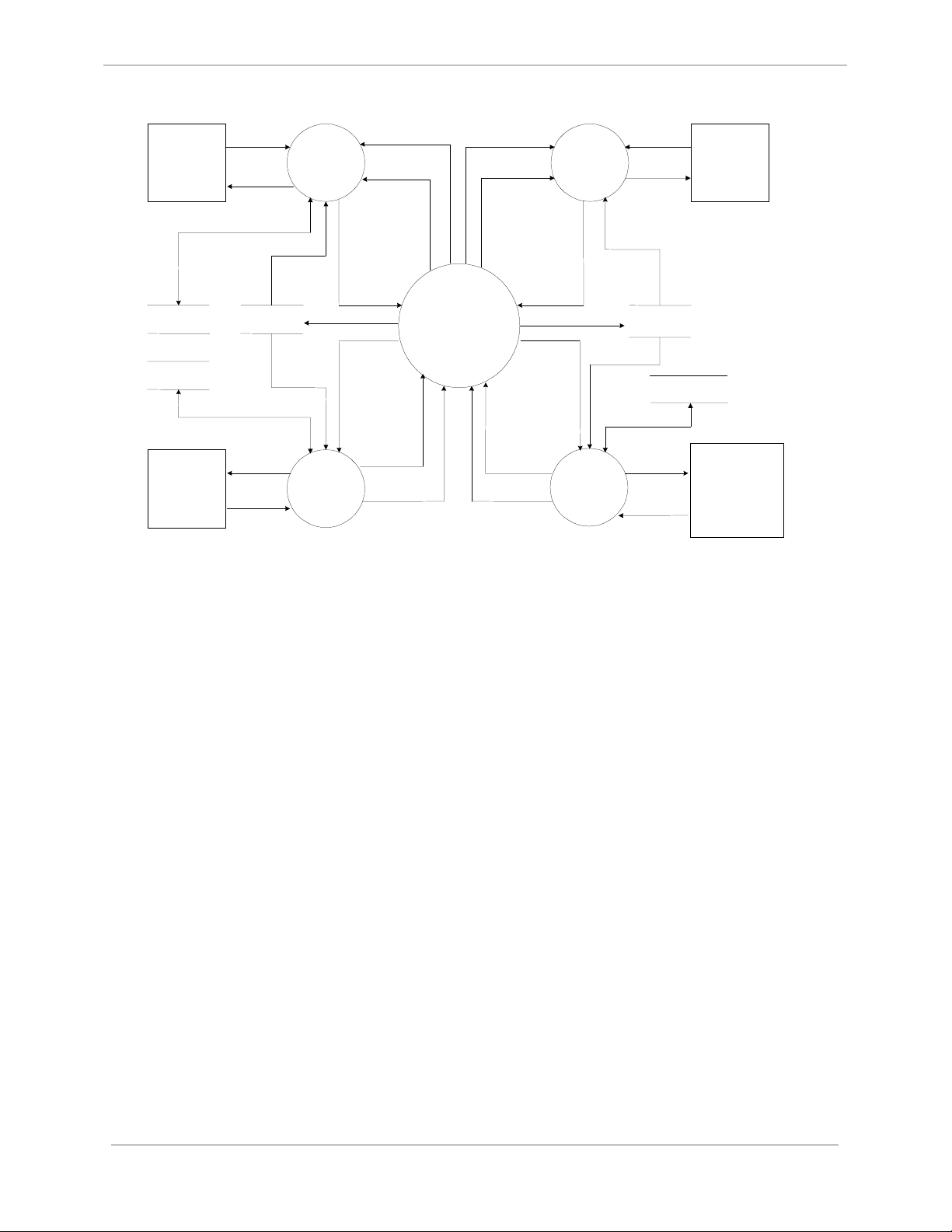
The C3000/C0300 DPA when resident in GE Power Systems along with the WESDAC Interface
Node (WIN) application provides translation of data between the WIN database and a
C3000/C0300 speaking host station. The WIN application and its database provide a consistent
means of transferring data between different DPAs and Data Collection Applications (DCAs)
within the GE Power Systems systems. For example, a WESDAC DCA may collect data from
field devices via protocol X and provide the information to WIN. A DPA may then get the data
from WIN and provide it to a host station via protocol Y (in this case C3000/C0300).
Conversely C3000/C0300 control requests may be received from a master station and passed to
WIN for execution. WIN may then pass these to a DCA, which utilize protocol X to have an end
field device actually perform the physical control operation. The interaction between the
C3000/C0300 DPA, WIN, and other applications resident within a typical WESDAC system is
illustrated in the following figure:
General A016-1CG-1.00-2
Full
xi
Page 12
GE Power Systems
Custom ABB C3000/C0300 DPA
Configuration Guide
C3000
Host
C3000
DPA Data
Local I/O
DCA Data
Local
Hardware
HOST
Command
DPA
Response
WESDAC
Tables
Data
Request
Requested
Data
C3000
DPA
Data
Update
Local I/O
DCA
WIN Response
WIN Event
WIN
Command
DCA
Command
DCA
Event
DCA
Response
WIN Response
WESDAC
Interface
Node
(WIN)
WIN Event
Command
Command
DCA
Event
DCA
Response
Figure 1. System Overview
WESMAINT
WIN
DCA
Collection
Application
Data
Update
Data
(DCA)
Operator
Request
Displa
y
Data
WESDAC
Tables
DCA Data
Data
Request
Requested
Data
WESMAINT
Display
(VT100)
Remote
Hardware
xii
A016-1CG-1.00-2 General
Full
Page 13
Chapter 1: Configuration Tables
The C3000/C0300 DPA is configured by means of the tables, which contain all of its
configuration data.
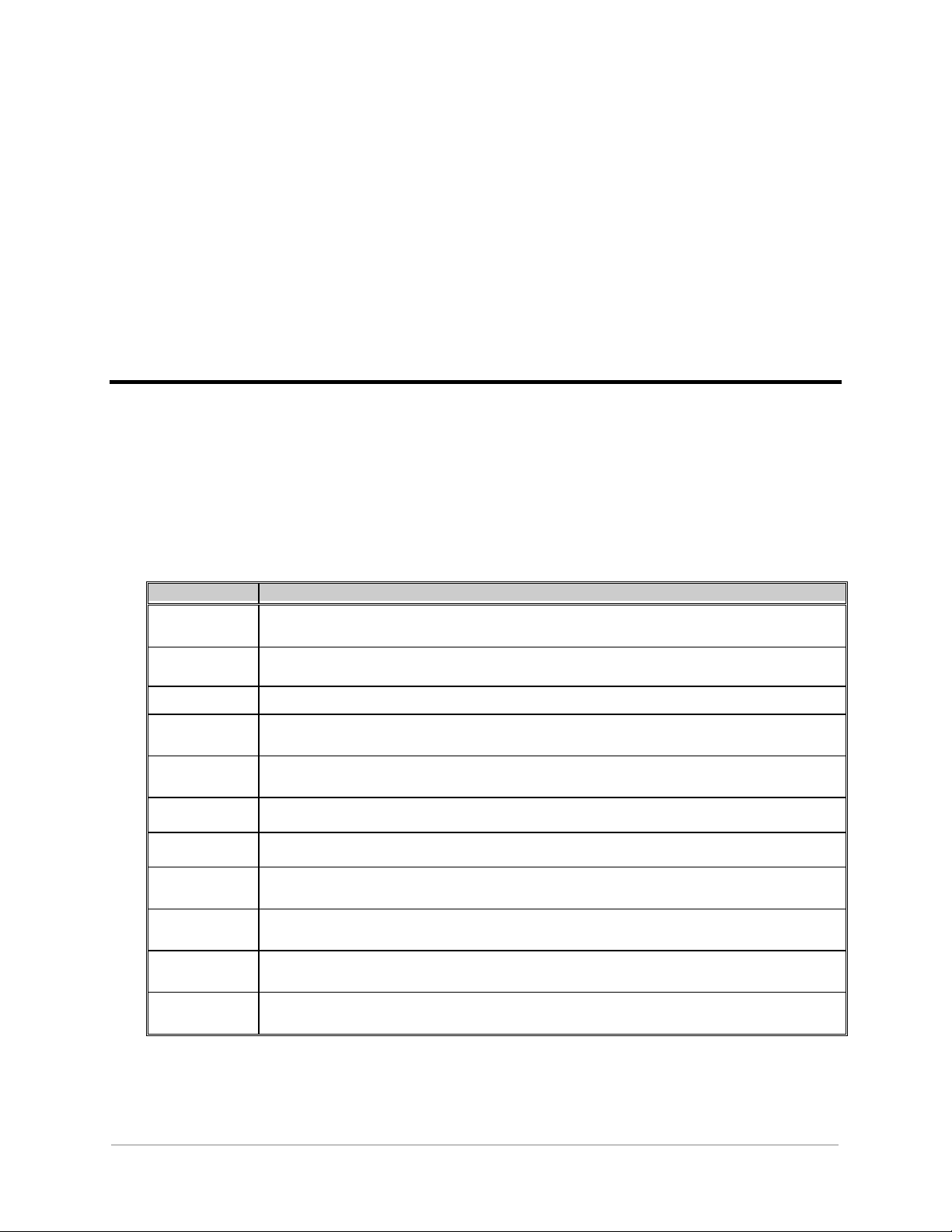
The purpose of each configuration table is described in the following table:
A016_COM This table contains parameters related to communication ports. One record is entered for each port the
application uses.
A016_XRF This table contains the cross-reference parameters between A016_LRU records and LRU addresses. One
record is entered for each LRU to be addressed.
A016_LRU This table contains parameters related to LRUs. One record is entered for each LRU in the system.
A016_GRP This table contains parameters related to groups of points in LRUs. One record is entered for each data
group on an LRU.
A016SCAN This table contains parameters related to scan sections within groups. One record is entered for each scan
section in a group.
A016_DI This table contains parameters to customize the use of status input points in the system. One record is
A016_AI This table contains parameters to customize the use of analog input points in the system. One record is
A016_ACC This table contains parameters to customize the use of accumulator input points in the system. One record
is entered for each accumulator input point used.
A016_TC This table contains parameters to customize the control out put points used for Trip or Close requests.
One record is entered for each Trip/Close point used.
A016_RL This table contains parameters to customize the control out put points used for Raise or Lower requests.
One record is entered for each Raise/Lower pair used.
A016_SP This table contains parameters to customize the analog and binary control output points used for
Setpoint requests. One record is entered for each setpoint used.
Table 1 Name and Description of Tables Used
General A016-1CG-1.00-2
Full
1
Page 14

GE Power Systems
1.1 Configuration Sequence
The following is a list of the steps required to configure the A016-1 C3000/C0300 DPA:
1. Edit the C3000/C0300 DPA configuration. Prepare it according to the guidelines in this
document and the specific use for which the C3000/C0300 DPA is required.
2. Edit the configuration for the other applications that will run on the product. Prepare them
according to their own configuration guides.
3. Generate the configuration and download it to the product using a Config Pro Configuration
System. The list of applications to be compiled must include the C3000/C0300 DPA,
application A016-1.
4. Restart the system. If the C3000/C0300 DPA encounters an error during its initialization, it
will log a message to the WESMAINT Error Log and then, depending on the severity of the
error, terminate or continue with its run-time function.
5. Check for error messages. Log into the WESMAINT maintenance interface, select the
System Functions item from the Main menu, and then select the Error Log item from the
System Functions menu. If any error messages are displayed, correct the problem as
described in Appendix A: Error Messages and repeat steps 3 through 5. When the
C3000/C0300 DPA has successfully validated all the configuration parameters, configuration
is complete.
Custom ABB C3000/C0300 DPA
Configuration Guide
2
A016-1CG-1.00-2 General
Full
Page 15
Chapter 2: Configuration the Port
Configuration Table (A016_COM)
The A016_COM table provides information for communication ports, which are used by the
C3000/C0300 DPA. It contains one record for each communication port configured to customize
the communications related settings for the C3000/C0300 DPA. The fields contained in the table
are described in the table below:
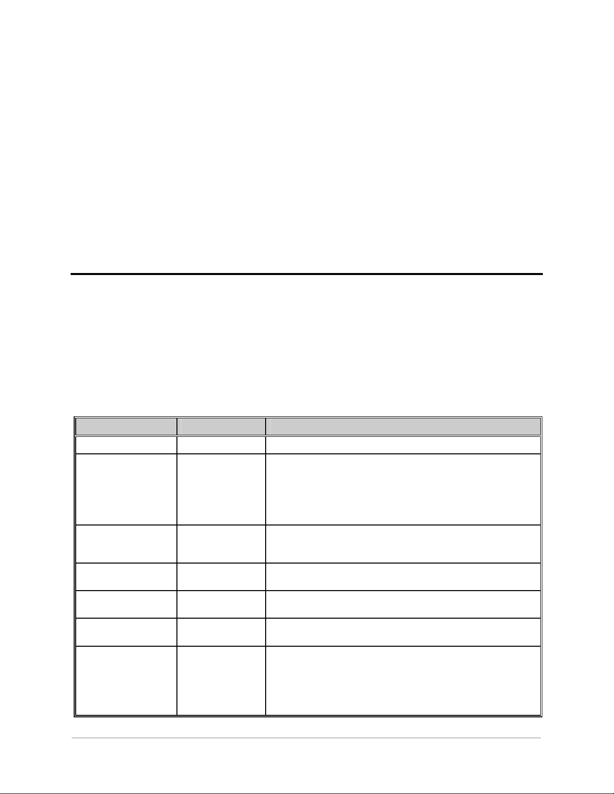
Table 2. C3000/C0300 A016_COM Configuration Table
Field Range Description
Port ID COM1 – COM7 ASCII name which defines the communication port name in the device.
Baud Rate 110, 300, 600, 1200,
1800, 2400, 4800,
7200, 9600
A016-1 DPA actual baud rate cannot be changed and is set to 9600 baud.
However, this setting can be used to change the RTS on time (pre
transmission delay).
RTS on time =
Default setting should be 9600.
Pre-TX Char * 8000 / Baud Rate.
Pre-TX Char 0 to 500 The number of Mark characters (8 bits of 1 = 0xFF), which is sent prior to
each message transmission. Note that the last character send prior to each
message is 0xFE to provide a start Space for master synchronization.
Post-TX Char 0 to 500 The number of Space characters (8 bits of 0 = Chars 0x00), which is sent
immediately after each message transmission before dropping the carrier.
TPTM Bias -32767 to 32767 The fine tuning (in 0.5 milli-seconds) of the remote turnaround delay time
that allows time compatibility with different systems.
TRX Bias -32767 to 32767 The fine tuning (in 0.5 milli-seconds) of the remote time at end of received
message that allows time compatibility with different systems.
Comm Fail Output Point
General A016-1CG-1.00-2
Full
Any valid system
Digital Output point
or Undefined (-1).
The system control DO point number, which is to be latched on when
communications fail. The control point is in the on state (contact closed)
when communications have failed, and in the off state (contact open)
when communications are restored. The high entry limit is confined to the
highest control point number configured in the system. The feature can be
disabled by setting this to Undefined (-1).
3
Page 16
Custom ABB C3000/C0300 DPA
GE Power Systems
Field Range Description
Comm Fail Timer 10 to 3600 The amount of time in seconds that the C3000/C0300 DPA waits to
receive an intelligible message from a master station before declaring
that communications have failed for the affected communication port.
This entry is ignored if the Fail Output option is Undefined (-1).
Configuration Guide
LRU Offset Indexes into
A016_XRF table.
Total LRUs 1 to 32767 The number of LRUs communicating on this port. This entry is used in
The one based offset from the first entry in the A016_XRF table, which
corresponds to this port. The A016
chapter.
conjunction with the XRF Offset entry to determine the exact range of
records in the A016
The high entry limit is confined to the number of records in the
A016_XRF table. Also the entered value, plus the XRF Offset entry, must
not exceed the number of records in the A016_XRF table.
XRF table that this communication port is to utilize.
_
XRF table is described in the next
_
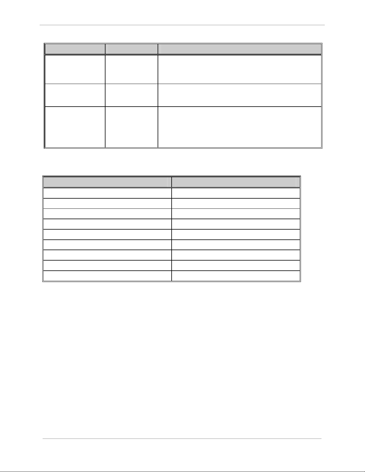
Table 3. Character Times at the selected Baud Rate
Baud Rate One Character Time(ms)
110 91
300 34
600 17
1200 9
1800 6
2400 5
4800 3
7200 2
9600 2
4
A016-1CG-1.00-2 General
Full
Page 17
Chapter 3: Configuring the C3000/C0300
DPA A016_XRF Table
This chapter describes entries the user must provide in the A016_XRF table found in the
C3000/C0300 DPA configuration.
3.1 General Information
The A016_XRF table provides information to cross-reference between communications ports and
LRUs, which are used by the C3000/C0300 DPA. It contains one record for each LRU
configured, and each record provides the station address to be used for the LRU and an offset into
the A016
LRU Address
LRU Offset Indexes into
LRU table. The fields contained in the table are described in the following table:
_
Field Range Description
0x01 – 0x0F, -1
A016_LRU table.
The hexadecimal address of the LRU associated with the entries of this record.
This is the address used in protocol messages for this LRU. Entries accepted by
the C3000/C0300 DPA correspond to the C3000/C0300 protocol valid address
range. Entering -1
The one based offset from the first entry in the A016_LRU table, which
corresponds to this record. The A016
disables the LRU.
LRU table is described in the next chapter.
_
Table 4 C3000/C0300 A016_XRF Configuration Table
General A016-1CG-1.00-2
Full
5
Page 18

GE Power Systems
Custom ABB C3000/C0300 DPA
Configuration Guide
6
A016-1CG-1.00-2 General
Full
Page 19

Chapter 4: Configuring the C3000/C0300
DPA A016_LRU Table
This chapter describes entries the user must provide in the A016_LRU table found in the
C3000/C0300 DPA configuration.
The A016_LRU table provides information for LRUs, which are used by the C3000/C0300 DPA.
It contains one record for each LRU configured, for database customization. The fields contained
in the table are described in the following table:
Table 5 A016_LRU Table Fields
Field Range Description
Local/Remote
Input
Any valid system Digital
Input point or Undefined
(-1).
The system DI point number, which is used to switch the LRU between local
and remote operation. In local mode, LRU controls are disabled, and in
remote mode, LRU controls are enabled. The high entry limit is confined to
the highest status point number configured in the system. Entering Undefined
(-1) disables the local/remote option and the LRU is always in remote mode
(controls enabled).
Local/Remote
State
Accum. Freeze
Output
Accum Freeze
Time
T/C Select
Timeout
General A016-1CG-1.00-2
Full
0 to 1 The state (0 or 1) of the local/remote input which corresponds to the local
(controls disabled) mode. This entry is ignored if the local/remote option is
disabled.
Any valid system Digital
Output point or
Undefined (-1).
1 to 60000 The time duration in milli-seconds that the freeze output relay is pulsed on.
1 to 60 The amount of time in seconds that the C3000/C0300 DPA allows execution
The system control output point number (zero-based), which is to be pulsed
on when an accumulator freeze (update) command is received from the
master station. The high entry limit is confined to the highest control point
number configured in the system. Entering -1 disables the freeze output
option.
This entry is ignored if the freeze output option is disabled.
of a trip or close request after enabling a control point selection.
7
Page 20

GE Power Systems
Field Range Description
Custom ABB C3000/C0300 DPA
Configuration Guide
Number of SOEs 10 to 255 (When SOE
Methods is set to Time
Correlated)
10 to 2000 (When SOE
Methods is set to Time
Sync)
Group Offset Indexes into A016_GRP
table.
Group Count 0 to 16 The number of A016_GRP records which correspond to this LRU. This entry
SOE Methods Time Correlated or Time
Sync
The maximum number of SOE events that can be buffered per group of points.
The one based offset from the first entry in the A016_GRP table. The
GRP table is described in a later chapter.
A016
_
is used in conjunction with the LRU Group Offset entry to determine the
exact range of records in the A016
Possible entries accepted by the C3000/C0300 DPA are from 0 to 16, but the
entered value, plus the LRU Group Offset entry, must not exceed the number
of records in the A016_GRP table.
This entry sets the SOE reply method when the master station sends a SOE
data request or a Scan Data request.
GRP table that this LRU is to utilize.
_
8
A016-1CG-1.00-2 General
Full
Page 21

Chapter 5: Configuring the C3000/C0300
DPA A016_GRP Table
This chapter describes entries the user must provide in the A016_GRP table found in the
C3000/C0300 DPA configuration.
The A016_GRP table provides information for groups of points associated with LRUs, which are
used by the C3000/C0300 DPA. It contains one record for each group of points configured, for
database customization. The fields contained in the table are described in the following table:
Table 6 A016_GRP Table Fields
Field Range Description
Group Number 0 to 15 The group number of the group of points referenced by this record.
Scan Offset Indexes into A016SCAN
table.
Scan Count
T/C Offset Indexes into A016_TC table. The one based offset from the first entry in the A016_TC table. The
T/C Count 0 to 12 The number of A016_TC records which correspond to this group. This entry
R/L Offset Indexes into A016_RL table. The one based offset from the first entry in the A016_RL table. The
General A016-1CG-1.00-2
Full
0 to 32
The one based offset from the first entry in the A016SCAN table. The
A016SCAN table is described in a later chapter.
The number of A016SCAN records which correspond to this group. This
entry is used in conjunction with the Scan Offset entry to determine the
exact range of records in the A016SCAN table that this group is to utilize.
Possible entries accepted by the C3000/C0300 DPA are from 0 to 32, but the
entered value, plus the Scan Offset entry, must not exceed the number of
records in the A016SCAN table.
TC table is described in a later chapter.
A016
_
is used in conjunction with the T/C Offset entry to determine the exact
range of records in the A016_TC table that this group is to utilize.
Possible entries accepted by the C3000/C0300 DPA are from 0 to 12, but the
entered value, plus the T/C Offset entry, must not exceed the number of
records in the A016_TC table.
A016_RL table is described in a later chapter.
9
Page 22

Custom ABB C3000/C0300 DPA
GE Power Systems
Field Range Description
R/L Count 0 to 3 The one based offset from the first entry in the A016_RL table. The
RL table is described in a later chapter.
A016
_
Set Point Offset Indexes into A016_SP table. The one based offset from the first entry in the A016_RL table. The
RL table is described in a later chapter.
A016
_
Set Point Count 0 to 2 The number of A016_SP records which correspond to this group. This
entry is used in conjunction with the SP Offset entry to determine the exact
range of records in the A016_SP table that this group is to utilize. Possible
entries accepted by the C3000/C0300 DPA are from 0 to 2, but the entered
value, plus the SP Offset entry, must not exceed the number of records in
the A016_SP table.
Configuration Guide
10
A016-1CG-1.00-2 General
Full
Page 23

Chapter 6: Configuring the C3000/C0300
DPA A016SCAN Table
This chapter describes entries the user must provide in the A016SCAN table found in the
C3000/C0300 DPA configuration.
The A016SCAN table provides information for scan sections of groups associated with LRUs,
which are used by the C3000/C0300 DPA. It contains one record for each scan section
configured, for database customization. The fields contained in the table are described in the
following table:
General A016-1CG-1.00-2
Full
11
Page 24

GE Power Systems
Field Range Description
Section
Type
Table
Offset
Echo Master
CONITEL Poll Word
SOE Poll Word
Terminal Status Word
Spare
MCD Status Data
Non-MCD status Data
Analog Data
Accumulator Data
Entry is either ignored,
or entry is a valid
System point, depending
on the Section Type.
Used to select the different types of data that can be returned in a scan selection. The
first selection of all scan groups must be defined as Echo Master.
Spare replies to the master station as all zeros.
Echo Master: Section offset entry is ignored.
CONITEL Poll Word: Section offset entry is ignored.
SOE Poll Word: Section offset entry is ignored.
Terminal Status Word: Section offset entry is ignored.
Spare: Section offset entry is ignored.
MCD Status Data: The Section Offset entry defines the zero based offset
from the first entry in the A016_DI table. The A016_DI
table is described in a later chapter.
Non-MCD status Data: The Section Offset entry defines the zero based offset
from the first entry in the A016_DI table. The A016_DI
table is described in a later chapter.
Analog Data: The Section Offset entry defines the zero based offset
from the first entry in the A016_AI table. The A016_AI
table is described in a later chapter.
Accumulator Data: The Section Offset entry defines the zero based offset
from the first entry in the A016_ACC table. The
A016_ACC table is described in a later chapter.
Custom ABB C3000/C0300 DPA
Configuration Guide
Table 7 A016SCAN Table Fields
12
A016-1CG-1.00-2 General
Full
Page 25

Chapter 7: Configuring the C3000/C0300
DPA A016_DI Table
This chapter describes entries the user must provide in the A016_DI table found in the
C3000/C0300 DPA configuration.
The A016_DI table provides information for system status input points, which are used by the
C3000/C0300 DPA. The table contains one record for each system status input point to
customize the usage of the point. The fields contained in the table are described in the following
table:
Field Range Description
DI Point
Any valid system Digital
Input point or Undefined (-1).
The system status input point number, which is used as one of the sources
for a scan section. The high entry limit is confined to the highest system
status input point configured in the system. Entering Undefined (-1)
causes the LRU to always return a constant value for this point as it is not
mapped to a real system status input point.
Invert
SOE Enable
Yes or No
Yes or No
Indicates if the System Status point value should be inverted by the DPA.
Indicates if the System Status point should be logged in the SOE buffer
(SOE enabled) or not (SOE disabled).
Table 8 A016_DI Table Fields
General A016-1CG-1.00-2
Full
13
Page 26

GE Power Systems
Custom ABB C3000/C0300 DPA
Configuration Guide
14
A016-1CG-1.00-2 General
Full
Page 27
Chapter 8: Configuring the C3000/C0300
DPA A016_AI Table
This chapter describes entries the user must provide in the A016_AI table found in the
C3000/C0300 DPA configuration.
The A016_AI table provides information for system analog input points, which are used by the
C3000/C0300 DPA. It contains one record for each system analog input point to customize the
usage of the point. The fields contained in the table are described in the following table:
Table 9 A016_AI Table Fields
Field Range Description
Analog Input
Point
Any valid system Analog
Input point or Undefined (-
1).
The system analog input point number, which is used as the source for a
scan section. The high entry limit is confined to the highest system analog
input point configured in the system. Entering -1 causes the LRU to always
return a zero value for this point, as it is not mapped to a real system analog
input point.
Conversion
Mode
Range
General A016-1CG-1.00-2
Full
Bipolar 2’s complement
Bipolar sign/magnitude
Unipolar
0 to 5000 The range used in converting the value of the system analog input point
The conversion mode specific to the system analog input point associated
with this record entry. It can be one of three modes, as follows:
Bipolar 2's complement (11 bits + sign)
Bipolar sign/magnitude (11 bits + sign)
Unipolar (12 bits, no sign)
associated with this record entry to a C3000/C0300 protocol value via the
formula:
C3000/C0300 value = (AI value * range / divisor) + offset
The typical entry is 2047, the full scale of the C3000/C0300 protocol for a
Bipolar analog value.
15
Page 28

Custom ABB C3000/C0300 DPA
GE Power Systems
Field Range Description
Divisor 1 to 35000
Offset -5000 to 5000
Dead Band 1 to 5000 If the C3000/C0300 protocol value of the system analog input point
Alarm Limit 0 to 5000 If the C3000/C0300 protocol value of the system analog input point
The divisor used in converting the value of the system analog input point
associated with this record entry to a C3000/C0300 protocol value via the
formula:
C3000/C0300 value = (AI value * range / divisor) + offset
The typical entry is 32767, the full-scale value of WIN database.
The offset used in converting the value of the system analog input point
associated with this record entry to a C3000/C0300 protocol value via the
formula:
C3000/C0300 value = (AI value * range / divisor) + offset
The typical entry is 00 for no offset.
associated with this record entry changes by more than the dead band limit
between master scans, the appropriate bit in the CONITEL polling word is
set.
associated with this record entry exceeds the range of the alarm limit; the
appropriate bit in the CONITEL polling word is set.
Configuration Guide
16
A016-1CG-1.00-2 General
Full
Page 29

Chapter 9: Configuration the
C3000/C0300 DPA A016_ACC Table
This chapter describes entries the user must provide in the A016_ACC table found in the
C3000/C0300 DPA configuration.
The A016_ACC table provides information for system accumulator input points, which are used
by the C3000/C0300 DPA. The table contains one record for each system accumulator input
point to customize the usage of the point. The fields contained in the table are described in the
following table:
Field Range Description
ACC Point
Any valid system
Accumulator Input point
or Undefined (-1).
The system accumulator input point number, which is used as the source for a
scan section. The high entry limit is confined to the highest system accumulator
input point configured in the system. Entering -1 causes the LRU to always
return a zero value for this point as it is not mapped to a real system
accumulator input point.
Type
Freeze Enable
Freeze-reset
Enabled
Counting
Method
Counter Source
12 bit Accumulator
Upper 12 bits
Lower 12 bits
Yes or No
Yes or No
Transition, Pulse
Frozen buffer, Running
buffer
Sets the accumulator to indicate that this record entry is either the top (Upper
12 bits) or bottom part (Lower 12 bits) of a 24 bit accumulator. Setting to 12
bit Accumulator indicates that the whole accumulator is only 12 bits long.
No indicates that master requests for accumulator freeze does not cause
transfer of running count buffer to frozen count buffer, Yes otherwise.
No indicates that master requests for accumulator freeze with reset does not
cause zeroing of the running count buffer, Yes otherwise.
Pulse indicates that pulse counting method is used in providing values to the
master station. Transition indicates that transition counting method is used in
providing values to the master station. Note that two transitions (changes of
state) of the accumulator input point is counted as a pulse.
Indicates if the running or frozen buffer is used in providing values to the
master station.
Table 10 A016_ACC Table Fields
General A016-1CG-1.00-2
Full
17
Page 30

GE Power Systems
Custom ABB C3000/C0300 DPA
Configuration Guide
18
A016-1CG-1.00-2 General
Full
Page 31

Chapter 10: Configuring the
C3000/C0300 DPA A016_TC Table
This chapter describes entries the user must provide in the A016_TC table found in the
C3000/C0300 DPA configuration.
The A016_TC table provides information for Trip/Close control output points, which are used by
the C3000/C0300 DPA. The table contains one record for each Trip/Close control output point to
customize the usage of the point. The fields contained in the table are described in the following
table:
Field Range Description
DO Point
Any valid system
Digital Output point or
Undefined (-1).
The system control output point number, which is used as the destination for a LRU
Trip/Close control point. The high entry limit is confined to the highest system control
output point configured in the system. Entering Undefined (-1) disables Tripping or
Closing of the protocol point corresponding to this record.
Trip
Duration
Close
Duration
Operation
Mode
1 to 60000
1 to 60000
T/C
Latch
Pulse
The amount of time in milli-seconds that the control output contact is to operate for
when a Trip is requested for the protocol point corresponding to this record.
The amount of time in milli-seconds that the control output contact is to operate for
when a Close is requested for the protocol point corresponding to this record.
The Trip/Close (T/C) mode of operation uses the Master Trip and Close relays in
conjunction with operation of the output relay. The configured Trip and Close
durations are used. The control board hardware must be configured to correspond to
this mode of operation.
The Latch mode of operation latches the output relay on or off. A Trip command from
the master latches the point off and a Close command from the master will latch the
point on. The configured Trip and Close durations are not used. The control board
hardware must be configured to correspond to this mode of operation.
The Pulse mode of operation does not use the Master Trip and Close relays in
conjunction with operation of the output relay. The configured Trip and Close durations
are used. The control board hardware must be configured to correspond to this mode of
operation.
Table 11 A016_TC Table Fields
General A016-1CG-1.00-2
Full
19
Page 32

GE Power Systems
Custom ABB C3000/C0300 DPA
Configuration Guide
20
A016-1CG-1.00-2 General
Full
Page 33

Chapter 11: Configuring the
C3000/C0300 DPA A016_RL Table
This chapter describes entries the user must provide in the A016_RL table found in the
C3000/C0300 DPA configuration.
The A016_RL table provides information for Raise/Lower control output points, which are used
by the C3000/C0300 DPA. The table contains one record for each Raise/Lower control output
point to customize the usage of the point. The fields contained in the table are described in the
following table:
Table 12 A016_RL Table Fields
Field Range Description
Raise DO Point
Any valid system Digital
Output point or Undefined (-1).
The system control output point number, which is used as the
destination for a Raise DO control point. The high entry limit is confined
to the highest system control output point configured in the system.
Entering Undefined (-1) disables Raising of the protocol point.
Raise Base
Duration
Raise Inc.
Duration
General A016-1CG-1.00-2
Full
0 to 30000
1 to 30000
This is the base duration, in milliseconds, used to operate for when a
Raise is requested for the protocol point corresponding to this record,
via the formula:
pulse duration = (inc. duration * mult.) + base duration
where the inc. duration is also configurable and the mult. factor is
specified in the master Raise/Lower request.
This is the incremental duration, in milli-seconds, used to specify how
long the control output contact is to operate for when a Raise is
requested for the protocol point corresponding to this record, via the
formula:
pulse duration = (inc. duration * mult.) + base duration
where the base duration is also configurable and the mult. factor is
specified in the master Raise/Lower request.
21
Page 34

GE Power Systems
Field Range Description
Lower DO Point
Any valid system Digital
Output point or Undefined (-1).
The system control output point number which is used as the destination
for a LRU Lower control point. The high entry limit is confined to the
highest system control output point configured in the system. Entering
Undefined (-1) disables Lowering of the protocol point corresponding
to this record.
Custom ABB C3000/C0300 DPA
Configuration Guide
Lower Base
Duration
Lower Inc.
Duration
0 to 30000
1 to 30000
This is the base duration, in milli-seconds, used to specify how long the
control output contact is to operate for when a Lower is requested for
the protocol point corresponding to this record, via the formula:
pulse duration = (inc. duration * mult.) + base duration
where the inc. duration is also configurable and the mult. factor is
specified in the master Raise/Lower request.
This is the incremental duration, in milli-seconds, used to specify how
long the control output contact is to operate for when a Lower is
requested for the protocol point corresponding to this record, via the
formula:
pulse duration = (inc. duration * mult.) + base duration
where the base duration is also configurable and the mult. factor is
specified in the master Raise/Lower request.
NOTE: The Raise/Lower command operates in the Pulse mode. The same relay number
may be entered for both the Raise point and the Lower point if desired, but
normally two different point relays are used. The C3000/C0300 DPA ensures that
the Raise point relay is off before operating the Lower point relay, and vice versa.
The WESDAC control board hardware must be configured to correspond to this
mode of operation.
22
A016-1CG-1.00-2 General
Full
Page 35

Chapter 12: Configuring the
C3000/C0300 DPA A016_SP Table
This chapter describes entries the user must provide in the A016_SP table found in the
C3000/C0300 DPA configuration.
The A016_SP table provides information for setpoints, which are used by the C3000/C0300
DPA. The table contains one record for each setpoint to customize the usage of the point. The
fields contained in the table are described in the following table:
Table 13 A016_SP Table Fields
Field Range Description
System point If System point set to Analog
Output:
Any valid system Analog
Output point or Undefined (-1).
If System point set to Digital
Output:
Any valid system Digital Output
point or Undefined (-1).
If System point is set to Analog Output this field is the system analog
output point number (zero-based), which is used as the destination for a
LRU Setpoint. The high entry limit is confined to the highest system
analog output point configured in the system.
If options set to Digital Output this field is the point number of the first of
twelve contiguous system control output points, which are used as the
destination for a LRU Setpoint. The high entry limit is confined to 11 less
than the highest system control output point configured in the system.
Options
General A016-1CG-1.00-2
Full
If System point set to Analog
Output:
AO: 2’s complement
AO: sign/magnitude
AO: unipolar
If System point set to Digital
Output:
DO: 2’s comp. D20 Latch
DO: sign/mag D20 Latch
DO: unipolar D20 Latch
DO: 2’s comp. Ext Latch
DO: sign/mag. Ext Latch
DO: unipolar Ext Latch
Specifies the setpoint output to either Analog Output or Digital Output’s
output in either 2’s complement, sign magnitude, or unipolar format.
23
Page 36

GE Power Systems
Field Range Description
Range
Divisor
0 to 35000 This field is used in conjunction with the Options entry. If the Options
entry is set to Digital Output, this field is ignored, else this field is the
range used in converting a C3000/C0300 protocol value to the value of
the system analog output point associated with this record entry, via the
formula:
Analog Output value = (C3000/C0300 value * range / divisor) + offset
The typical entry is 32767, the full scale value of WIN database.
1 to 5000 This field is used in conjunction with the Options entry. If the Options
entry is set to DO, this field is ignored, else this field is the divisor used
in converting a C3000/C0300 protocol value to the value of the system
analog output point associated with this record entry, via the formula:
Analog Output value = (C3000/C0300 value * range / divisor) + offset
The typical entry is 2047, the full scale of the C3000/C0300 protocol for
a Bipolar analog output.
Custom ABB C3000/C0300 DPA
Configuration Guide
Offset
DO Operate
Time
DO Delay Time
-30000 to 30000 This field is used in conjunction with the Options entry. If the Options
entry is set to AO, this field is the offset used in converting a
C3000/C0300 protocol value to the value of the system analog output
point associated with this record entry, via the formula:
Analog Output value = (C3000/C0300 value * range / divisor) + offset
If the Options entry is set to DO, this field is the offset used in
converting a C3000/C0300 protocol value to the value of the 12
contiguous system control output points associated with this record
entry, via the formula:
Digital Output value = C3000/C0300 value + offset
The typical entry is 0 for no offset.
1 to 1000
1 to 1000 If the options for the setpoint record are configured to perform a digital
If the options for the setpoint record are configured to perform a digital
output setpoint via external latching relays, this field is used as the
control pulse operation time in milliseconds for latching or de-latching
the relays.
output setpoint via external latching relays, this field is used as the
delay time in milliseconds between issuing a de-latch output and a
subsequent latch output to the relays.
24
A016-1CG-1.00-2 General
Full
Page 37

Appendix A: Error Messages
The C3000/C0300 DPA logs messages to the WESMAINT II Error Log display when run time
errors occur. The messages are divided into two categories, the first being fatal error messages
and the second being warning messages.
Fatal errors messages are logged when the application is unable to recover from an error
condition and must suspend operation. Warning messages are logged when an error is not severe
enough to require that the program suspend operation, but functionality of the application may be
compromised.
When any of the messages listed in this appendix are logged to the Error Log display, they are
prefixed with the C3000/C0300 DPA identifier "A016" or "A016-<y>-<zz> where <y> identifies
a C3000/C0300 DPA sub-process and <zz> identifies a specific instance of the sub-process.
The symbol <xx> shown in some of the error messages listed in this appendix represents a
variable value. When the error is logged, the <xx> symbol is replaced by an alphanumeric value
specific to the occurrence of the error.
Many fatal errors may be remedied by the user as noted in the description of each error. Upon
occasion however, it may be necessary to contact the GE Power Systems Customer Service
Department in regard to a logged error. In this case the exact text of the message should be
reported in order to assure correct diagnosis of the problem.
General A016-1CG-1.00-2
Full
25
Page 38

GE Power Systems
A.1 Fatal Error Messages
ERR 1000: TERMINATING, PRIMARY CONFIG NOT FOUND
Why:
• The application cannot find its primary configuration information table A016_COM.
Remedy:
• Review the section in this document about configuring the A016_COM table and verify the
table has been correctly defined and loaded into memory. NOTE: The A016_COM table
may be deleted from memory in order to intentionally disable the application.
ERR 1001: NO A016_COM RECORDS FOUND
Why:
Custom ABB C3000/C0300 DPA
Configuration Guide
• The application found an A016_COM configuration table in memory, but the table
contained no records.
Remedy:
• Ensure that at least one record has been defined and loaded into memory for the A016_COM
table.
ERR 1002: NO A016_XRF RECORDS FOUND
Why:
• The application could not find any A016_XRF configuration table records in memory.
Remedy:
• Ensure that at least one record has been defined and loaded into memory for the A016_XRF
table.
ERR 1003: NO A016_LRU RECORDS FOUND
Why:
• The application could not find any A016_LRU configuration table records in memory.
Remedy:
• Ensure that at least one record has been defined and loaded into memory for the A016_LRU
table.
26
A016-1CG-1.00-2 General
Full
Page 39

Custom ABB C3000/C0300 DPA
Configuration Guide
GE Power Systems
ERR 1004: NO A016_GRP RECORDS FOUND
Why:
• The application could not find any A016_GRP configuration table records in memory.
Remedy:
• Ensure that at least one record has been defined and loaded into memory for the A016_GRP
table.
ERR 1100: WIN OPEN FAIL, ERR = < xx>
Why:
• The application cannot attach to WIN. Remedy:
• Contact the Customer Service Department and report this error.
ERR 1101: CAN'T SPAWN PROCESS
Why:
• The application cannot spawn a required communication port task or LRU task.
Remedy:
• Contact the Customer Service Department and report this error.
ERR 1102: CREATE EXCHANGE FAIL, ERR = < xx>
Why:
• The application cannot create a required internal message exchange.
Remedy:
• Contact the Customer Service Department and report this error.
ERR 1103: CANNOT ALLOCATE RAM
Why:
• The application cannot allocate required RAM memory.
Remedy:
• Increase the amount of RAM available in the system or reduce the RAM requirements of
the configured applications. If neither of these remedies is sufficient, contact the
Customer Service Department and report the error.
General A016-1CG-1.00-2
Full
27
Page 40

Custom ABB C3000/C0300 DPA
GE Power Systems
ERR 1104: Error creating message exchange
Why:
• The application was not able to create a message exchange process.
Remedy:
• Contact the Customer Service Department and report the error.
•
ERR 1105: ERROR ATTACHING TO SEMAPHORE
Why:
• The application was not able attach a semaphore to a LRU.
Remedy:
• Contact the Customer Service Department and report the error.
•
Configuration Guide
ERR 1106: ERROR ATTACHING TO SEMAPHORE
Why:
• The application was not able attach a semaphore to the port data structure.
Remedy:
• Contact the Customer Service Department and report the error.
ERR 1200: PORT TASK, CAN'T OPEN PORT <xx> Why:
• The task for the indicated port can't open the port. Remedy:
• Ensure that the displayed text string represents a valid port for the GE Power Systems
product being utilized, and that no other application is configured to use the same port. If
the text string is valid and no other application is configured to use the port, contact the
Customer Service Department and report the error.
ERR 1201: PORT TASK, CAN'T INIT PORT <xx>
Why:
• The task for the indicated port cannot initialize the communication settings or
communication timing for the port after it had been opened successfully.
Remedy:
• Contact the Customer Service Department and report this error.
28
A016-1CG-1.00-2 General
Full
Page 41

Custom ABB C3000/C0300 DPA
Configuration Guide
GE Power Systems
ERR 1300: LRU TASK WIN OPEN ERR = <xx>
Why:
• A LRU task cannot attach to WIN. Remedy:
• Contact the Customer Service Department and report this error.
ERR 1301: LRU TASK REPORT ENABLE FAIL
Why:
• A LRU task cannot enable reporting of binary input events from the WIN subsystem.
Remedy:
• Contact the Customer Service Department and report this error.
ERR 1400: SETPOINT TASK WIN OPEN ERR = <xx>
Why:
• The setpoint task cannot attach to WIN. Remedy:
• Contact the Customer Service Department and report this error.
ERR 2000: INVALID BAUD RATE, REC <xx>
Why:
• The Baud Rate entry for the indicated A016_COM record number is not within the valid
entry range described earlier in this document.
Remedy:
• Modify and re-download the configuration with a correct entry in the specified configuration
record.
ERR 2001: INVALID PRE TX MARK, REC <xx>
Why:
• The Pre-TX Mark Chars entry for the indicated A016_COM record number is not within the
valid entry range described earlier in this document.
Remedy:
• Modify and re-download the configuration with a correct entry in the specified configuration
record.
General A016-1CG-1.00-2
Full
29
Page 42

Custom ABB C3000/C0300 DPA
GE Power Systems
Configuration Guide
ERR 2002: INVALID POST TX SPACE, REC <xx>
Why:
• The Post-TX Space Chars entry for the indicated A016_COM record number is not within
the valid entry range described earlier in this document.
Remedy:
• Modify and re-download the configuration with a correct entry in the specified configuration
record.
ERR 2003: INVALID COMM FAIL POINT, REC <xx>
Why:
• The Fail Output entry for the indicated A016_COM record number is not within the valid
entry range described earlier in this document.
Remedy:
• Modify and re-download the configuration with a correct entry in the specified configuration
record.
ERR 2004: INVALID COMM FAIL TIME, REC <xx>
Why:
• The Fail Time entry for the indicated A016_COM record number is not within the valid
entry range described earlier in this document.
Remedy:
• Modify and re-download the configuration with a correct entry in the specified configuration
record.
ERR 2005: INVALID XRF OFFSET, REC <xx>
Why:
• The XRF Offset entry for the indicated A016_COM record number is not within the valid
entry range described earlier in this document.
Remedy:
• Modify and re-download the configuration with a correct entry in the specified configuration
record.
30
A016-1CG-1.00-2 General
Full
Page 43

Custom ABB C3000/C0300 DPA
Configuration Guide
GE Power Systems
ERR 2006: INVALID LRU COUNT, REC <xx>
Why:
• The LRU Count entry for the indicated A016_COM record number is not within the valid
entry range described earlier in this document.
Remedy:
• Modify and re-download the configuration with a correct entry in the specified configuration
record.
ERR 2007: INVALID OFFSET/COUNT, REC <xx>
Why:
• The XRF Offset and LRU Count entries for the indicated A016_COM record number, in
combination, are not within the valid entry range described earlier in this document.
Remedy:
• Modify and re-download the configuration with correct entries in the specified configuration
record.
ERR 2008: DUPLICATE LRU ADDRESS, REC <xx>
Why:
• The LRU address for the indicated A016
XRF record number is the same as another one for
_
the same communications port. LRU addresses must be unique for all LRUs associated with
a communications port.
Remedy:
• Modify and download the configuration with correct entries in the specified configuration
record.
ERR 2100: INVALID ADDRESS, REC <xx>
Why:
• The LRU Address entry for the indicated A016_XRF record number is not within the valid
entry range described earlier in this document.
Remedy:
• Modify and re-download the configuration with a correct entry in the specified configuration
record.
General A016-1CG-1.00-2
Full
31
Page 44

Custom ABB C3000/C0300 DPA
GE Power Systems
Configuration Guide
ERR 2101: INVALID OFFSET, REC <xx>
Why:
• The LRU Offset entry for the indicated A016_XRF record number is not within the valid entry
range described earlier in this document.
Remedy:
• Modify and re-download the configuration with a correct entry in the specified configuration
record.
ERR 2200: INVALID LOCAL/REMOTE POINT, REC <xx>
Why:
• The Local/Remote entry for the indicated A016_LRU record number is not within the valid
entry range described earlier in this document.
Remedy:
• Modify and re-download the configuration with a correct entry in the specified configuration
record.
ERR 2201: INVALID LOCAL STATE, REC <xx>
Why:
• The Local State entry for the indicated A016_LRU record number is not within the valid
entry range described earlier in this document.
Remedy:
• Modify and re-download the configuration with a correct entry in the specified configuration
record.
ERR 2202: INVALID FREEZE POINT, REC <xx>
Why:
• The Freeze Output entry for the indicated A016_LRU record number is not within the valid
entry range described earlier in this document.
Remedy:
• Modify and re-download the configuration with a correct entry in the specified configuration
record.
32
A016-1CG-1.00-2 General
Full
Page 45

Custom ABB C3000/C0300 DPA
Configuration Guide
GE Power Systems
ERR 2203: INVALID FREEZE DURATION, REC <xx>
Why:
• The Freeze Duration entry for the indicated A016_LRU record number is not within the
valid entry range described earlier in this document.
Remedy:
• Modify and re-download the configuration with a correct entry in the specified configuration
record.
ERR 2204: INVALID T/C TIMEOUT, REC <xx>
Why:
• The T/C Timeout entry for the indicated A016_LRU record number is not within the valid
entry range described earlier in this document.
Remedy:
• Modify and re-download the configuration with a correct entry in the specified configuration
record.
ERR 2206: INVALID GROUP OFFSET, REC <xx>
Why:
• The LRU Group Offset entry for the indicated A016_LRU record number is not within the
valid entry range described earlier in this document.
Remedy:
• Modify and re-download the configuration with a correct entry in the specified configuration
record.
ERR 2207: INVALID GROUP COUNT, REC <xx>
Why:
• The LRU Group Count entry for the indicated A016_LRU record number is not within the
valid entry range described earlier in this document.
Remedy:
• Modify and re-download the configuration with a correct entry in the specified configuration
record.
General A016-1CG-1.00-2
Full
33
Page 46

Custom ABB C3000/C0300 DPA
GE Power Systems
Configuration Guide
ERR 2208: INVALID GROUP OFFSET/COUNT, REC <xx>
Why:
• The LRU Group Offset and LRU Group Count entries for the indicated A016_LRU record
number, in combination, are not within the valid entry range described earlier in this
document.
Remedy:
• Modify and re-download the configuration with correct entries in the specified configuration
record.
ERR 2300: INVALID GROUP NUMBER, REC <xx>
Why:
• The Group No entry for the indicated A016_GRP record number is not within the valid
entry range described earlier in this document.
Remedy:
• Modify and re-download the configuration with a correct entry in the specified configuration
record.
ERR 2301: INVALID SCAN COUNT, REC <xx>
Why:
• The Scan Count entry for the indicated A016_GRP record number is not within the valid entry
range described earlier in this document.
Remedy:
• Modify and re-download the configuration with a correct entry in the specified configuration
record.
34
A016-1CG-1.00-2 General
Full
Page 47

Custom ABB C3000/C0300 DPA
Configuration Guide
GE Power Systems
ERR 2302: INVALID SCAN OFFSET, REC <xx>
Why:
• The Scan Offset entry for the indicated A016_GRP record number is not within the valid entry
range described earlier in this document.
Remedy:
• Modify and re-download the configuration with a correct entry in the specified configuration
record.
ERR 2303: INVALID SCAN OFFSET/COUNT, REC <xx>
Why:
• The Scan Offset and Scan Count entries for the indicated A016_GRP record number, in
combination, are not within the valid entry range described earlier in this document.
Remedy:
• Modify and re-download the configuration with correct entries in the specified configuration
record.
ERR 2304: INVALID T/C COUNT, REC <xx>
Why:
• The T/C Count entry for the indicated A016_GRP record number is not within the valid entry
range described earlier in this document.
Remedy:
• Modify and re-download the configuration with a correct entry in the specified configuration
record.
ERR 2305: INVALID T/C OFFSET, REC <xx>
Why:
• The T/C Offset entry for the indicated A016_GRP record number is not within the valid entry
range described earlier in this document.
Remedy:
• Modify and re-download the configuration with a correct entry in the specified configuration
record.
General A016-1CG-1.00-2
Full
35
Page 48

Custom ABB C3000/C0300 DPA
GE Power Systems
Configuration Guide
ERR 2306: INVALID T/C OFFSET/COUNT, REC <xx>
Why:
• The T/C Offset and T/C Count entries for the indicated A016_GRP record number, in
combination, are not within the valid entry range described earlier in this document.
Remedy:
• Modify and re-download the configuration with correct entries in the specified configuration
record.
ERR 2307: INVALID R/L COUNT, REC <xx>
Why:
• The R/L Count entry for the indicated A016_GRP record number is not within the valid entry
range described earlier in this document.
Remedy:
• Modify and re-download the configuration with a correct entry in the specified configuration
record.
ERR 2308: INVALID R/L OFFSET, REC <xx>
Why:
• The R/L Offset entry for the indicated A016_GRP record number is not within the valid entry
range described earlier in this document.
Remedy:
• Modify and re-download the configuration with a correct entry in the specified configuration
record.
ERR 2309: INVALID R/L OFFSET/COUNT, REC <xx>
Why:
• The R/L Offset and R/L Count entries for the indicated A016_GRP record number, in
combination, are not within the valid entry range described earlier in this document.
Remedy:
• Modify and re-download the configuration with correct entries in the specified configuration
record.
36
A016-1CG-1.00-2 General
Full
Page 49

Custom ABB C3000/C0300 DPA
Configuration Guide
GE Power Systems
ERR 2310: INVALID S/P COUNT, REC <xx>
Why:
• The SP Count entry for the indicated A016_GRP record number is not within the valid entry
range described earlier in this document.
Remedy:
• Modify and re-download the configuration with a correct entry in the specified configuration
record.
ERR 2311: INVALID S/P OFFSET, REC <xx>
Why:
• The SP Offset entry for the indicated A016_GRP record number is not within the valid entry
range described earlier in this document.
Remedy:
• Modify and re-download the configuration with a correct entry in the specified configuration
record.
ERR 2312: INVALID S/P OFFSET/COUNT, REC <xx>
Why:
• The SP Offset and SP Count entries for the indicated A016
GRP record number, in
_
combination, are not within the valid entry range described earlier in this document.
Remedy:
• Modify and re-download the configuration with correct entries in the specified configuration
record.
ERR 2313: SECTION 1 NOT MASTER ECHO, REC <xx>
Why:
• The first A016SCAN section mapped in the indicated A016_GRP record number is not
defined as a master echo type.
Remedy:
• Modify and re-download the configuration with correct entries in the specified configuration
record.
General A016-1CG-1.00-2
Full
37
Page 50

Custom ABB C3000/C0300 DPA
GE Power Systems
Configuration Guide
ERR 2314: INVALID SOE GROUP METHOD REC <xx>
Why:
• The A016_GRP table has an invalid SOE group method. This may be caused by the
corruption of the configuration table.
• Remedy:
• Rebuild and re-download the configuration. If the problem persists contact customer service.
ERR 2400: INVALID SECTION TYPE, REC <xx>
Why:
• The Section Type entry for the indicated A016SCAN record number is not within the valid
entry range described earlier in this document.
Remedy:
• Modify and re-download the configuration with a correct entry in the specified configuration
record.
ERR 2401: INVALID TABLE OFFSET, REC <xx>
Why:
• The Section Offset entry for the indicated A016SCAN record number is not within the valid
entry range described earlier in this document.
Remedy:
• Modify and re-download the configuration with a correct entry in the specified configuration
record.
ERR 2500: INVALID POINT, REC <xx>
Why:
• The DI Point Number entry for the indicated A016_DI record number is not within the valid
entry range described earlier in this document.
Remedy:
• Modify and re-download the configuration with a correct entry in the specified configuration
record.
38
A016-1CG-1.00-2 General
Full
Page 51

Custom ABB C3000/C0300 DPA
Configuration Guide
GE Power Systems
ERR 2501: INVALID OPTIONS, REC <xx>
Why:
• The DI Point Options entry for the indicated A016_DI record number is not within the valid
entry range described earlier in this document.
Remedy:
Modify and re-download the configuration with a correct entry in the specified
•
configuration record.
ERR 2600: INVALID POINT, REC <xx>
Why:
• The AI Point Number entry for the indicated A016_AI record number is not within the valid
entry range described earlier in this document.
Remedy:
• Modify and re-download the configuration with a correct entry in the specified configuration
record.
ERR 2601: INVALID MODE, REC <xx>
Why:
• The Conversion Mode entry for the indicated A016_AI record number is not within the
valid entry range described earlier in this document.
Remedy:
• Modify and re-download the configuration with a correct entry in the specified configuration
record.
ERR 2602: INVALID RANGE, REC <xx>
Why:
• The Range entry for the indicated A016_AI record number is not within the valid entry range
described earlier in this document.
Remedy:
• Modify and re-download the configuration with a correct entry in the specified configuration
record.
General A016-1CG-1.00-2
Full
39
Page 52

Custom ABB C3000/C0300 DPA
GE Power Systems
Configuration Guide
ERR 2603: INVALID DIVISOR, REC <xx>
Why:
• The Divisor entry for the indicated A016_AI record number is not within the valid entry
range described earlier in this document.
Remedy:
• Modify and re-download the configuration with a correct entry in the specified configuration
record.
ERR 2604: INVALID OFFSET, REC <xx>
Why:
• The Offset entry for the indicated A016_AI record number is not within the valid entry
range described earlier in this document.
Remedy:
• Modify and re-download the configuration with a correct entry in the specified configuration
record.
ERR 2605: INVALID DEADBAND, REC <xx>
Why:
• The Dead Band entry for the indicated A016_AI record number is not within the valid entry
range described earlier in this document.
Remedy:
• Modify and re-download the configuration with a correct entry in the specified configuration
record.
ERR 2606: INVALID LIMIT, REC <xx>
Why:
• The Alarm Limit entry for the indicated A016_AI record number is not within the valid
entry range described earlier in this document.
Remedy:
• Modify and re-download the configuration with a correct entry in the specified configuration
record.
40
A016-1CG-1.00-2 General
Full
Page 53

Custom ABB C3000/C0300 DPA
Configuration Guide
GE Power Systems
ERR 2700: INVALID POINT, REC <xx>
Why:
• The AC Point Number entry for the indicated A016_ACC record number is not within the
valid entry range described earlier in this document.
Remedy:
• Modify and re-download the configuration with a correct entry in the specified configuration
record.
ERR 2701: INVALID OPTIONS, REC <xx>
Why:
• The AC Point Options entry for the indicated A016_ACC record number is not within the
valid entry range described earlier in this document.
Remedy:
• Modify and re-download the configuration with a correct entry in the specified configuration
record.
ERR 2800: INVALID POINT NUMBER, REC <xx>
Why:
• The T/C Point Number entry for the indicated A016_TC record number is not within the valid
entry range described earlier in this document.
Remedy:
• Modify and re-download the configuration with a correct entry in the specified configuration
record.
General A016-1CG-1.00-2
Full
41
Page 54

Custom ABB C3000/C0300 DPA
GE Power Systems
Configuration Guide
ERR 2801: INVALID TRIP DURATION, REC <xx>
Why:
• The Trip Duration entry for the indicated A016_TC record number is not within the valid
entry range described earlier in this document.
Remedy:
• Modify and re-download the configuration with a correct entry in the specified configuration
record.
ERR 2802: INVALID CLOSE DURATION, REC <xx>
Why:
• The Close Duration entry for the indicated A016_TC record number is not within the valid
entry range described earlier in this document.
Remedy:
• Modify and re-download the configuration with a correct entry in the specified configuration
record.
ERR 2803: INVALID OPERATION MODE, REC <xx>
Why:
• The Operation Mode entry for the indicated A016_TC record number is not within the valid
entry range described earlier in this document.
Remedy:
• Modify and re-download the configuration with a correct entry in the specified configuration
record.
ERR 2900: INVALID RAISE POINT, REC <xx>
Why:
• The Raise Point Number entry for the indicated A016_RL record number is not within the
valid entry range described earlier in this document.
Remedy:
• Modify and re-download the configuration with a correct entry in the specified configuration
record.
42
A016-1CG-1.00-2 General
Full
Page 55

Custom ABB C3000/C0300 DPA
Configuration Guide
GE Power Systems
ERR 2901: INVALID RAISE BASE DURATION, REC <xx>
Why:
• The Raise Base Duration entry for the indicated A016_RL record number is not within the
valid entry range described earlier in this document.
Remedy:
• Modify and re-download the configuration with a correct entry in the specified configuration
record.
ERR 2902: INVALID RAISE INC DURATION, REC <xx>
Why:
• The Raise Inc. Duration entry for the indicated A016_RL record number is not within the
valid entry range described earlier in this document.
Remedy:
• Modify and re-download the configuration with a correct entry in the specified configuration
record.
ERR 2903: INVALID LOWER POINT, REC <xx>
Why:
• The Lower Point Number entry for the indicated A016_RL record number is not within the
valid entry range described earlier in this document.
Remedy:
• Modify and re-download the configuration with a correct entry in the specified configuration
record.
ERR 2904: INVALID LOWER BASE DURATION, REC <xx>
Why:
• The Lower Base Duration entry for the indicated A016_RL record number is not within the
valid entry range described earlier in this document.
Remedy:
• Modify and re-download the configuration with a correct entry in the specified configuration
record.
General A016-1CG-1.00-2
Full
43
Page 56

Custom ABB C3000/C0300 DPA
GE Power Systems
Configuration Guide
ERR 2905: INVALID LOWER INC DURATION, REC <xx>
Why:
• The Lower Inc. Duration entry for the indicated A016_RL record number is not within the
valid entry range described earlier in this document.
Remedy:
• Modify and re-download the configuration with a correct entry in the specified configuration
record.
ERR 3000: INVALID POINT NUMBER, REC <xx>
Why:
• The Setpoint Number entry for the indicated A016_SP record number is not within the valid
entry range described earlier in this document.
Remedy:
• Modify and re-download the configuration with a correct entry in the specified configuration
record.
ERR 3001: INVALID OPTIONS, REC <xx>
Why:
• The Setpoint Options entry for the indicated A016_SP record number is not within the valid
entry range described earlier in this document.
Remedy:
• Modify and re-download the configuration with a correct entry in the specified configuration
record.
ERR 3002: INVALID RANGE, REC <xx>
Why:
• The Range entry for the indicated A016_SP record number is not within the valid entry range
described earlier in this document.
Remedy:
• Modify and re-download the configuration with a correct entry in the specified configuration
record.
44
A016-1CG-1.00-2 General
Full
Page 57

Custom ABB C3000/C0300 DPA
Configuration Guide
GE Power Systems
ERR 3003: INVALID DIVISOR, REC <xx>
Why:
• The Divisor entry for the indicated A016_SP record number is not within the valid entry
range described earlier in this document.
Remedy:
• Modify and re-download the configuration with a correct entry in the specified configuration
record.
ERR 3004: INVALID OFFSET, REC <xx>
Why:
• The Offset entry for the indicated A016_SP record number is not within the valid entry range
described earlier in this document.
Remedy:
• Modify and re-download the configuration with a correct entry in the specified configuration
record.
ERR 3005: INVALID OPERATE TIME, REC <xx>
Why:
• The Operate Time entry for the indicated A016_SP record number is not within the valid entry
range described earlier in this document.
Remedy:
• Modify and re-download the configuration with a correct entry in the specified configuration
record.
ERR 3006: INVALID DELAY TIME, REC <xx>
Why:
• The Delay Time entry for the indicated A016_SP record number is not within the valid entry
range described earlier in this document.
Remedy:
• Modify and re-download the configuration with a correct entry in the specified configuration
record.
General A016-1CG-1.00-2
Full
45
Page 58

GE Power Systems
A.2 Warning Messages
The following warning messages are caused by errors within WIN, pSOS, or other function
calls within the application. If you encounter one of these messages, note the exact text of the
displayed message and contact the GE Power Systems Customer Service Department to report the
problem.
• WARNING, WIN DPA CLOSE FAILED, STATUS = <xx>
• WARNING, DPA READY COMMAND FAILED
• WARNING, CAN'T ENABLE RX ON PORT <xx>, ERR = <xx>
• WARNING, SIO_CN_RX_HIT ERR = <xx>
• WARNING, CAN'T DISABLE RX ON PORT <xx>, ERR = <xx>
• WARNING, RUN TIME ERROR, PORT <xx> TX WRITE ERR = <xx>
Custom ABB C3000/C0300 DPA
Configuration Guide
• WARNING, RUN TIME ERROR, PORT <xx>, CAN'T CHANGE RTS OFF DELAY
• WARNING, RUN TIME ERROR, SEND_X, ERR = <xx>
• WARNING, RUN TIME ERROR, WIN WRITE, ERR = <xx>
• WARNING, RUN TIME ERROR, RX'D NACK FOR CONTROL REQUEST
• WARNING, RUN TIME ERROR, RX'D NACK FOR ACCUM REQUEST
• WARNING, RUN TIME ERROR, SIGNAL_V, ERR = <xx>
• WARNING, RUN TIME ERROR, CANNOT ALLOCATE RAM
• WARNING, RUN TIME ERROR, SET TX DELAY, ERR = <xx>
• WARNING, RUN TIME ERROR, GET RX TIME, ERR = <xx>
• WARNING, UNABLE TO RESET SYSTEM
46
A016-1CG-1.00-2 General
Full
 Loading...