

Page 1

Please read before using feature module.
800-EFM
Note: The 800-EFM External Feature Module can be
set as a music on hold adapter, external paging
adapter, or a door intercom adapter
Model 800-EFM
External Feature Module
User’s Guide
Page 2

i
Getting Started
Getting Started
Congratulations! You’ve purchased a TMC Model 800-EFM External Feature
Module that meets the highest standards for quality and convenience in the Small
Office/Home Office environment. To get the most from your Feature Module,
please take time to read this guide thoroughly.
IMPORTANT SAFETY INSTRUCTIONS
When using your telephone equipment, basic safety precautions should always
be followed to reduce the risk of fire, electric shock and injury to persons, including the following:
1.
2.
3.
4.
5.
SAVE THESE INSTRUCTIONS
Do not use this product near water, for example, near a bath tub, wash bowl,
kitchen sink, or laundry tub, in a wet basement, or near a swimming pool.
Avoid using a telephone (other than a cordless type) during an electrical
storm. There may be a remote risk of electric shock from lightning.
Do not use the telephone to report a gas leak in the vicinity of the leak.
Use only the power cord and batteries indicated in this manual. Do not dispose of batteries in a fire. They may explode. Check with local codes for possible special disposal instructions.
Use only the class 2 power adapter 12VDC 500 mA.
!
Page 3
The TMC Model 800-EFM External Feature Module is designed for easy installation in your
home or office. However, it is important that you follow these few simple guidelines:
- Take a few minutes to read this manual so that you thoroughly understand the instructions to
be followed for proper installation of your Feature Module.
- This User’s Guide provides easy to understand directions for operation of your Feature
Module. Please retain these instructions for future reference.
The Model 800-EFM External Feature Module offers ONE of the following features, which
you decide by setting switches on the module: External Paging Adapter, Door Intercom
Adapter, or Music on Hold Adapter. If you ever need more than one of these features, you
must buy additional modules and set each one separately.
For setting this Module as an External Paging Adapter, please refer to sections 1A and 1B.
For setting this Module as an Door Intercom Adapter, please refer to sections 2A and 2B.
For setting this Module as a Music on Hold Adapter, please refer to sections 3A and 3B.
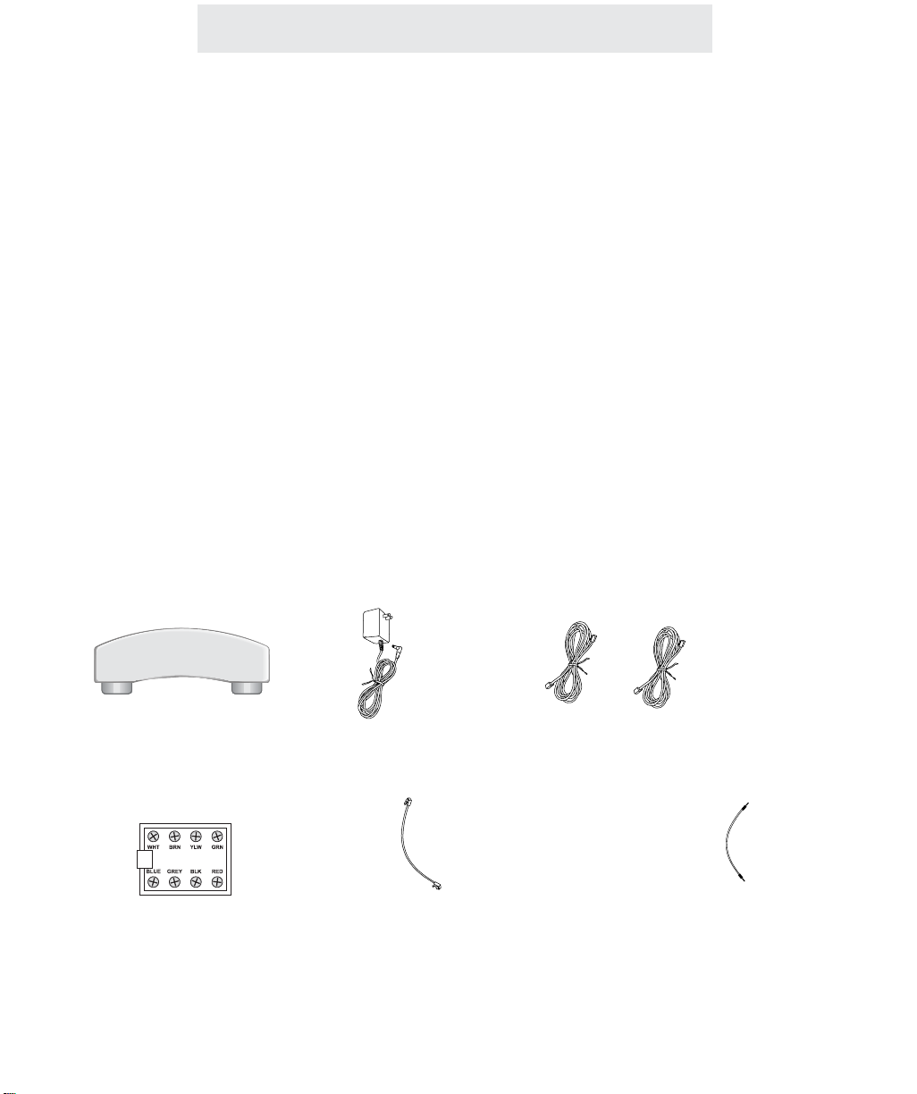
Packing List
Remove the unit from the package and check this list to be certain all parts are included:
ii
Before you begin . . .
To order any packing list items, call toll-free 1-800-TMC-1638.
Feature Module
Two Telephone Line Cords
Wiring Block
8-wire Cord for connecting the
Wiring Block to the Feature Module
Audio Cable for
Music on Hold Adapter
AC Adapter
Getting Started
Page 4

Getting Started . . . . . . . . . . . . . . . . . . . . . . . . . . . . . . . . . . . . . . . . . . . .i
Reference Drawing . . . . . . . . . . . . . . . . . . . . . . . . . . . . . . . . . . . . . . . .v
Section 1A - Installing Your External Paging Adapter . . . . . . . . . . . . .1-7
Step 1: Connect Line Cord . . . . . . . . . . . . . . . . . . . . . . . . . . . . . . .2
Step 2: Set DIP Switches to Proper Postions . . . . . . . . . . . . . . . . .3
Step 3: Connect Power Cord . . . . . . . . . . . . . . . . . . . . . . . . . . . . .4
Step 4: Connect Wiring Block to External Paging Adapter . . . . . . .5
Step 5: Connect Amplifier and Speaker to Wiring Block . . . . . . . . .6
Step 6: Adjust Speaker Volume to Desired Level . . . . . . . . . . . . . .7
Section 1B - Using Your External Paging Adapter . . . . . . . . . . . . . . . .9-12
Operation of your External Paging Adapter . . . . . . . . . . . . . . . . . .10
Important Points to Note . . . . . . . . . . . . . . . . . . . . . . . . . . . . . . . .11
Troubleshooting Guide . . . . . . . . . . . . . . . . . . . . . . . . . . . . . . . . . .12
Section 2A - Installing Your Door Intercom Adapter . . . . . . . . . . . . . . .13-20
Step 1: Connect Line Cord . . . . . . . . . . . . . . . . . . . . . . . . . . . . . . .14
Step 2: Set DIP Switches to Proper Postions . . . . . . . . . . . . . . . . .15
Step 3: Connect Power Cord . . . . . . . . . . . . . . . . . . . . . . . . . . . . .16
Step 4: Connect Wiring Block to Door Intercom Adapter . . . . . . . . .17
Step 5: Connect Door Speaker to Wiring Block . . . . . . . . . . . . . . . .18
Step 6: Connect Doorbell to Wiring Block . . . . . . . . . . . . . . . . . . . .19
Step 7: Connect Magnetic Door Strike to Wiring Block (Optional) . .20
Section 2B - Using Your Door Intercom Adapter . . . . . . . . . . . . . . . . .21-24
Operation of your Door Intercom Adapter . . . . . . . . . . . . . . . . . . . .22
Important Points to Note . . . . . . . . . . . . . . . . . . . . . . . . . . . . . . . .23
Troubleshooting Guide . . . . . . . . . . . . . . . . . . . . . . . . . . . . . . . . . .24
Table of Contents
iii
Page 5

Section 3A - Installing Your Music On Hold Adapter . . . . . . . . . . . . . .25-29
Step 1: Connect Line Cords . . . . . . . . . . . . . . . . . . . . . . . . . . . . . .26
Step 2: Set DIP Switches to Proper Positions . . . . . . . . . . . . . . . . .27
Step 3: Connect Power Cord . . . . . . . . . . . . . . . . . . . . . . . . . . . . .28
Step 4: Connect Music Source . . . . . . . . . . . . . . . . . . . . . . . . . . . .29
Section 3B - Using Your Music On Hold Adapter . . . . . . . . . . . . . . . . .31-36
Providing Music to Callers on Hold . . . . . . . . . . . . . . . . . . . . . . . .32
Providing a Recorded Message to Callers on Hold . . . . . . . . . . . . .33
Adjusting Music Volume . . . . . . . . . . . . . . . . . . . . . . . . . . . . . . . . .34
Usage Notes . . . . . . . . . . . . . . . . . . . . . . . . . . . . . . . . . . . . . . . . .35
Troubleshooting Guide . . . . . . . . . . . . . . . . . . . . . . . . . . . . . . . . . .36
Section 4 - Additional Information . . . . . . . . . . . . . . . . . . . . . . . . . . . . .37-39
Warranty Information . . . . . . . . . . . . . . . . . . . . . . . . . . . . . . . . . . .37
FCC Information . . . . . . . . . . . . . . . . . . . . . . . . . . . . . . . . . . . . . .38
iv
Table of Contents
Page 6
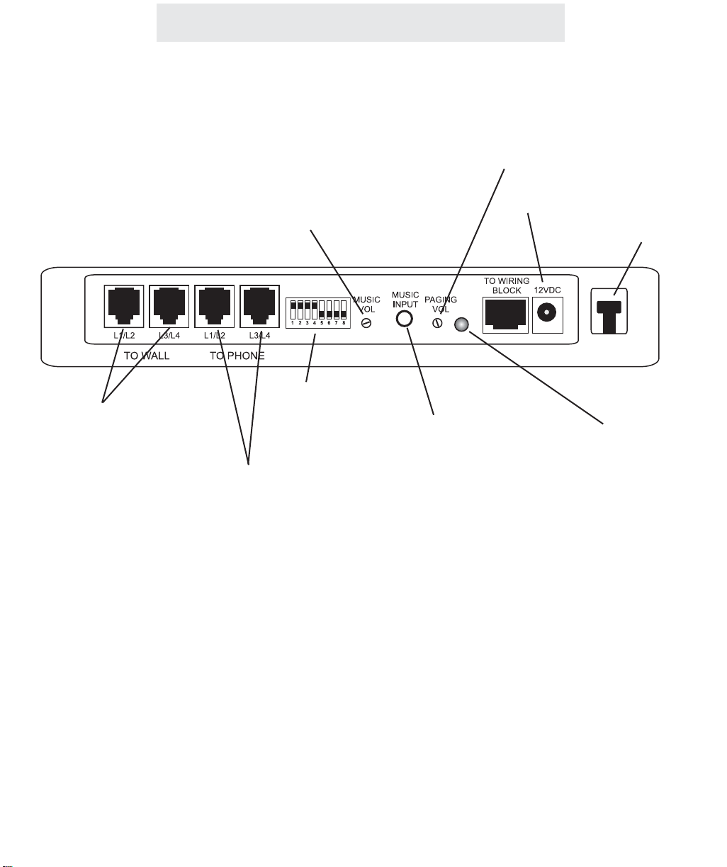
Reference Drawing
v
Strain Relief Tab
Jacks for connection
to Wall
Jacks for connection
to a Phone
Status Indicator Lamp
Dip Switches
Paging Volume Control Knob
for External Paging Adapter
AC Adapter Jack
Music Input Jack
for Music on Hold Adapter
Music Volume Control Knob
for Music on Hold Adapter
Page 7

Installing Your External Paging Adapter
Section
1A
Installing
Your
External
Paging Adapter
1
Page
2 Step 1: Connect Line Cord
3 Step 2: Set DIP Switches to
Proper Positions
4 Step 3: Connect Power Cord
5 Step 4: Connect Wiring Block
to External Paging Adapter
6 Step 5: Connect Amplifier and
Speaker to Wiring Block
7 Step 6: Adjust Speaker Volume
to Desired Level
Page 8
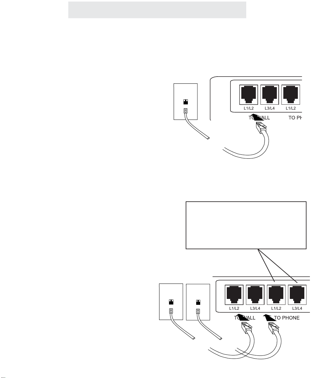
Step 1: Connect Line Cord
1 Connect Line Cord
Connect one end of a long telephone line cord
to the jack on the back of the feature module
labeled L1/L2. Connect the other end to a jack
labeled Lines 1 & 2 or to a jack labeled line 1.
PLEASE NOTE: You must be sure to
connect the cord to LINE 1. It does
not matter if it is also connected to
line 2.
Note also that you can install your feature module into a jack that is already being used by
another device. Simply unplug the other
device from the wall jack and plug it into the
corresponding jack on the feature module
labeled “TO PHONE.” Then connect a line cord
from the wall jack to the corresponding jack on
the feature module labeled “TO WALL.”
IMPORTANT NOTE: If you connect both the
L1/L2 and L3/L4 line cords from a device to the
jacks on the module labeled “TO PHONE,”
then you MUST connect both the L1/L2 and the
L3/L4 line cords from the wall jacks to the jacks
on the module labeled “TO WALL.”
2
Installing Your External Paging Adapter
L1/L2
Lines
1&2
L1/L2
L3/L4
Lines
1&2
Lines
3&4
If you wish to plug in the module to a jack
that is already in use, unplug the existing
device from the wall jacks, connect both of
the line cords to the module as shown,
and then plug the device into the jacks on
the module labeled “TO PHONE.”
Page 9
Installing Your External Paging Adapter
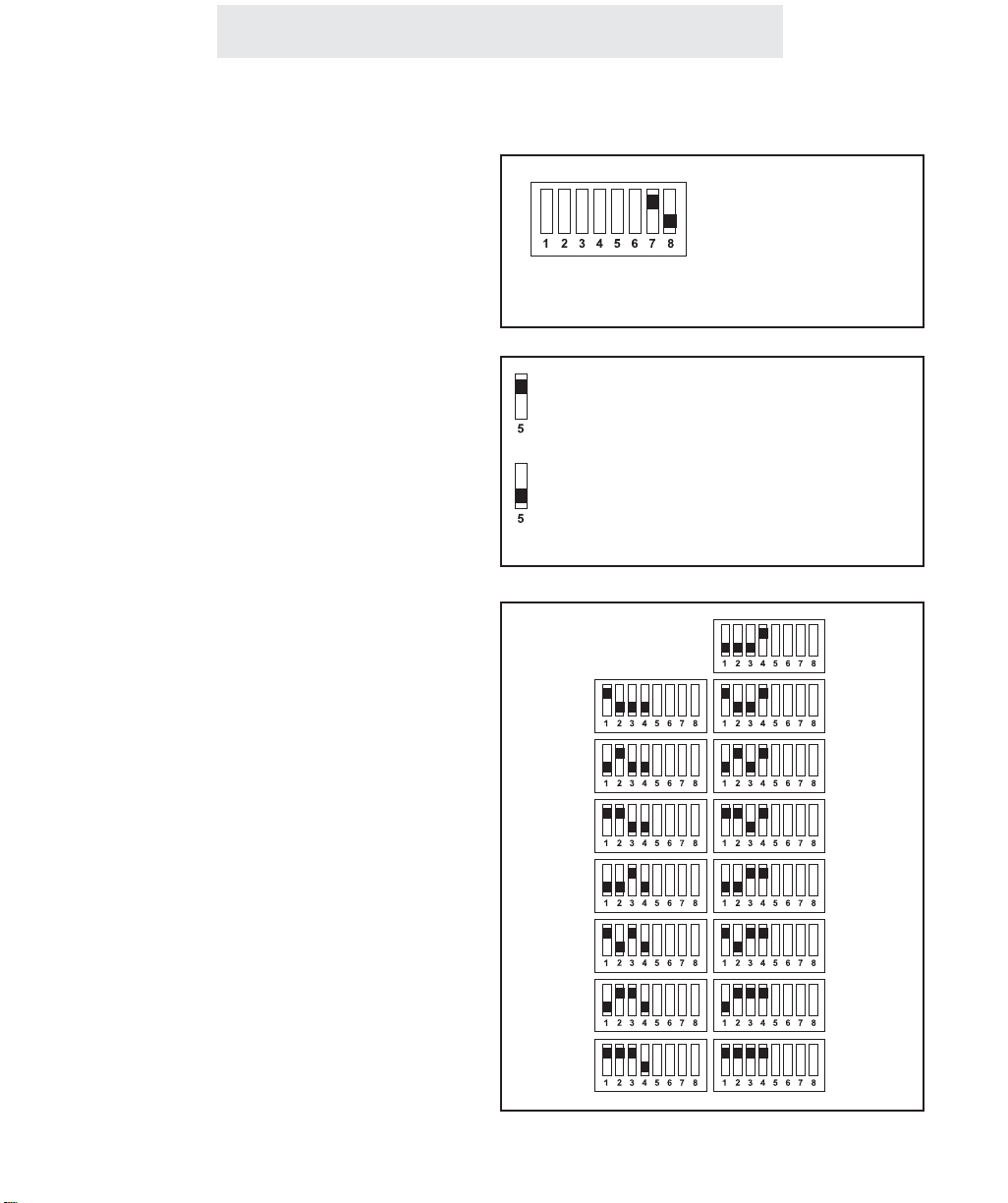
Step 2: Set DIP Switches to Proper Positions
Set Switches 7-8
Set switch 7 in the up position and switch
8 in the down position to set this feature
module as an External Paging Adapter.
Set Switch 5
The setting of this DIP switch determines
whether your External Paging Adapter will
accept or block All Pages.
If you want to be able to make announcements through this speaker, but do not
want general voice pages to be heard
through this speaker, you must set this
DIP switch in the down position.
Set Switches 1-4
The setting of these four DIP switches
determines what station number your
External Paging Adapter will be set as.
You may choose any station number from
12 to 26. Note that you may not set your
External Paging Adapter as station #11.
Also please note that you must not assign
your External Paging Adapter the same
station number as any of your phones or
other feature modules. IT MUST BE
ASSIGNED ITS OWN UNIQUE STATION
NUMBER.
Refer to the drawing at right to determine
how to set the DIP switches for the station
number you choose.
Set switch 5 in the up position to set
this External Paging Adapter to allow
All Pages
Set switch 5 in the down position to
set this External Paging Adapter to
block All Pages
IMPORTANT: Make
sure that switch 7 is
set in the up position
and switch 8 is set in
the down position.
Stn 12
Stn 13
Stn 14
Stn 15
Stn 16
Stn 17
Stn 18
Stn 19
Stn 20
Stn 21
Stn 22
Stn 23
Stn 24
Stn 25
Stn 26
3
Page 10
Step 3: Connect Power Cord
Installing Your External Paging Adapter
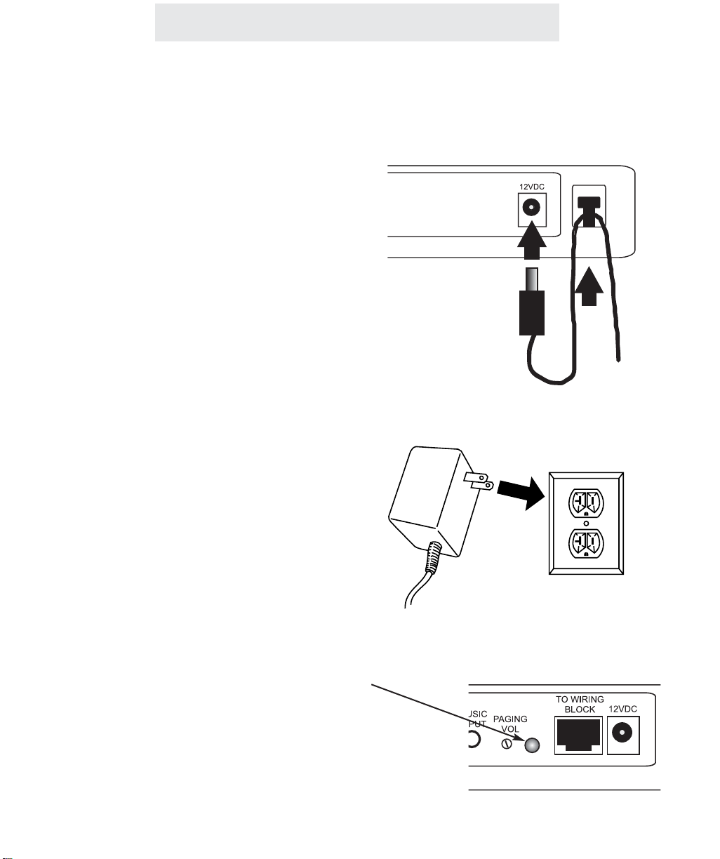
1 Connect Power Cord to Module
Plug the AC power cord into the adapter jack at
the rear of the Feature Module. Thread the
power cord around the strain relief tab.
2 Connect Power Cord to Wall Outlet
Plug the AC adapter into an electrical outlet not
controlled by a wall switch.
3 Make Sure that Status Indicator lamp
is Blinking
This indicates that the feature module is properly connected to electrical power.
The blinking pattern for the External Paging
Adapter is two blinks every few seconds.
4
Page 11
Step 4: Connect Wiring Block to External Paging Adapter
Installing Your External Paging Adapter
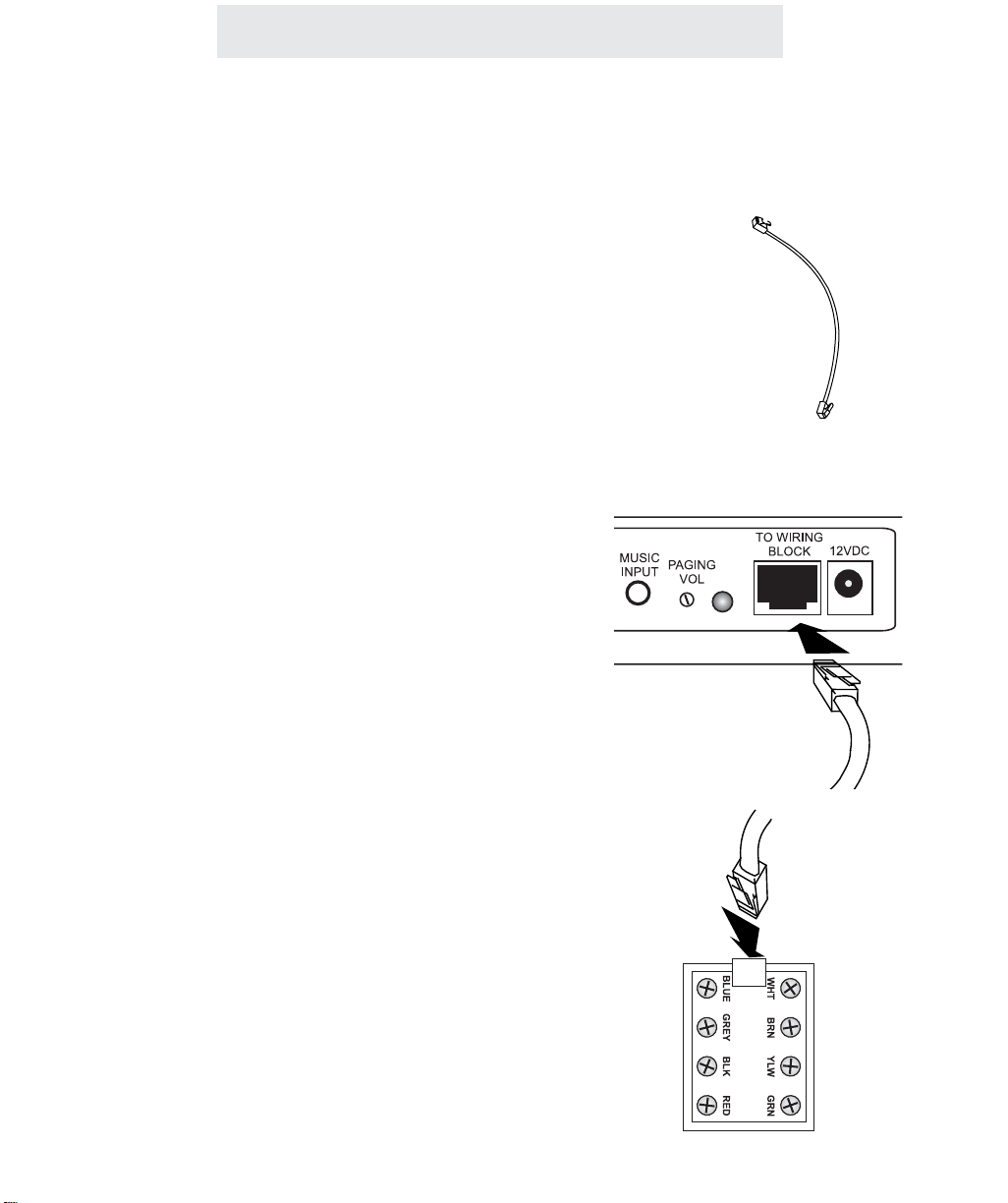
1 Locate 8-wire Cord
Find the 8-wire cord which was enclosed with
your External Paging Adapter. Note that this is
a black cord which is approximately 6 inches
long.
Note that you must use this cord, as any other
cord may not work.
2 Connect Cord to Feature Module
Plug one end of the 8-wire cord into the jack on
the back of your External Paging Adapter
labeled “TO WIRING BLOCK.”
3 Connect other end of Cord to Wiring
Block
Plug the other end of the 8-wire cord into the
wiring block which was supplied with your feature module.
5
Page 12
Installing Your External Paging Adapter
Step 5: Connect Amplifier and Speaker to Wiring Block
1 Install Amplifier and Speaker
Please follow the installation instructions that
came with your amplifier and speaker.
Note that you may be installing a speaker with
a built-in amplifier. These are called “amplified
speakers” or “self-powered speakers”. In this
case you would not need an external amplifier.
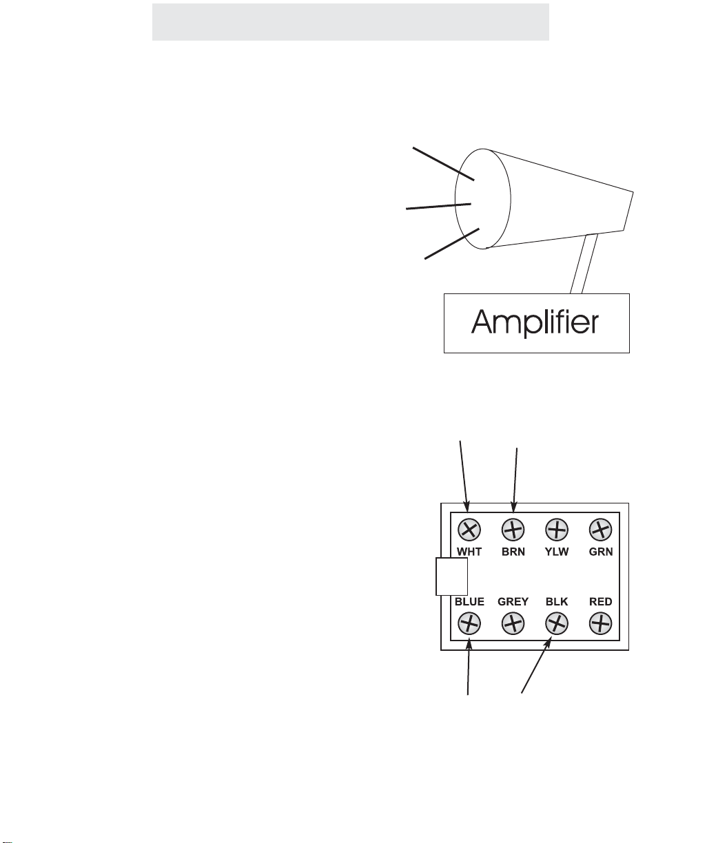
2 Connect Wiring Block to Input of
Amplifier
Connect the input of the amplifier to the indicated screw terminals on the wiring block.
Note that if the input level of the amplifier is
less than -25dBm, you should connect the
amplifier to the BLUE and BLACK wires. If the
input level of the amplifer is greater than 25dBm, you should connect the amplifier to the
WHITE and BROWN wires.
Note that if you have connected a self-amplified speaker, you would of course be connecting these terminals directly to the speaker.
Note that TMC does not include any cables for
connecting the wiring block to the amplifier.
This is because different amplifiers have many
different types of input connectors. Some have
RCA jacks, some have 1/8” jacks, some have
screw terminals, and so on. Connector cables
are sold many places, for example Radio
Shack. (For instance their RCA plug to lug
connector is part #42-2450, their 1/8” plug to
lug connector is part #42-2454, and their lug to
lug connector is part #42-2446.)
TMC recommends Valcom model V-1030C
self-amplified speaker. This model expects
input level from -15dBm to 10dBm. Therefore
you would connect this model to the WHITE
and BROWN wires.
Connect these terminals to the external
paging amplifier if input level is greater
than -25dBm
Connect these terminals to the external
paging amplifier if input level is less
than -25dBm
( - )
( - )
( + )
( + )
Page 13
Installing Your External Paging Adapter
Step 6: Adjust Speaker Volume to Desired Level
1 Listen to Speaker Volume
At the System phone nearest the External
Paging Adapter, make an announcement
through that external speaker (see page 10 for
instructions on doing this). Listen to the volume of your announcement through the speaker, or ask someone else to make the
announcement while you listen to the volume
level.
2 Adjust the Volume of the Speaker
Use the volume control knob on the amplifier to
achieve your desired speaker volume. Note
that if your speaker has a built-in amplifier, the
volume control knob may be on the speaker
itself.
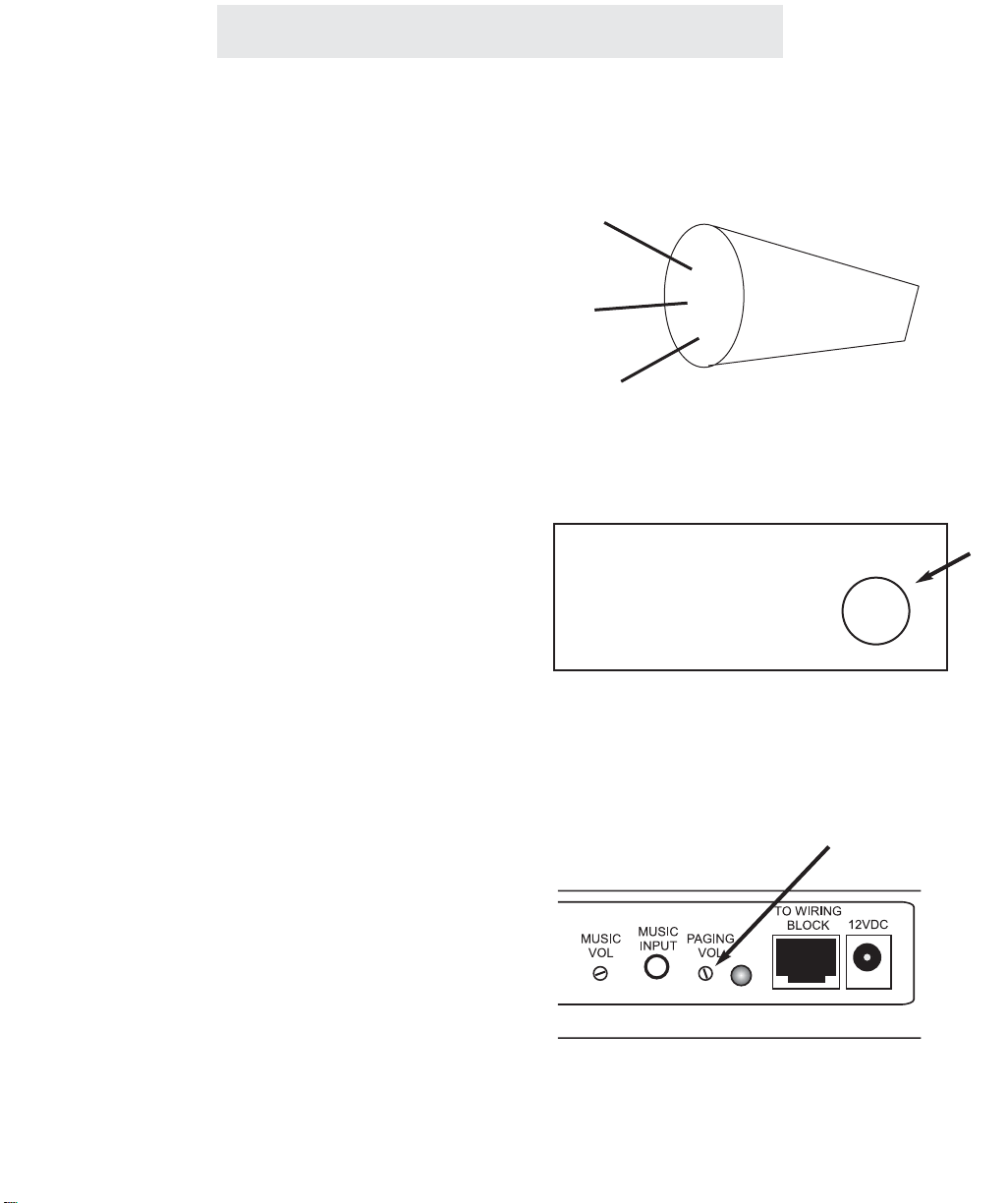
3 If Necessary, use the Feature
Module’s Volume Control Knob
If you find that you cannot achieve the desired
volume level by adjusting the volume of the
amplifier (or self-amplified speaker), then use
the paging volume control on the rear of the
Feature Module. Using a small screw driver,
turn the knob in a clockwise direction to
increase the volume level, or counter-clockwise to decrease the volume.
Note: This paging volume control on the module is only active when the amplifier is connected to the blue and black terminals.
Amplifier
Volume
7
Page 14

9
Using Your External Paging Adapter
Section
1B
Using Your
External
Paging
Adapter
Page
10 Operation of your External
Paging Adapter
11 Important Points to Note
12 Troubleshooting Guide
Page 15

10
Using Your External Paging Adapter
Operation of your External Paging Adapter
To make an announcement through
a particular external speaker:
1 Press PAGE.
2 Dial the two-digit station number of
the speaker you wish to page.
3 After you hear the paging tone,
speak towards the telephone or lift
the handset to make your
announcement.
4 Replace the handset in the cradle or
press the SPEAKER button to hang
up.
To make an All Page:
1 Press the PAGE button twice.
2 After you hear the paging tone,
speak towards the telephone or lift
the handset to make your
announcement.
3 Replace the handset in the cradle or
press the SPEAKER button to hang
up.
You may connect as many External Paging
Adapters to your system as you like. Connect
each one to a separate amplifier and speaker
and assign each a different station number from
12 to 26 (See page 3)
When you wish to make an announcement
through a particular external speaker, simply
press the PAGE, then dial the two-digit station
number of that external paging adapter.
The All Page feature enables you to make
announcements through all of the other system
stations, as well as through all external paging
adapters you have connected to your system.
When you make an All Page, your announcement will be heard at all phones that are not in
use and do not have their DO NOT DISTURB or
Page Block activated. In addition, your
announcement will be heard through all external
speakers connected to external paging adapters
that do not have their Page Block activated.
Note: If you do not want All Pages to be heard
through a particular external speaker, you must
activate that external paging adapter’s page
block by setting its Dip switch 5 in the down position (see page 3).
Page 16

Important Points to Note
Using Your External Paging Adapter
11
You must attach your External Paging Adapter to line 1 for it to function.
You may connect up to 15 External Paging Adapters to your system. Connect
each one to a separate External Paging speaker and assign each one a different station number from 12 to 26.
You must assign each external paging adapter its own unique station number, and you must make sure that you have not assigned the same station
number to another system telephone, another external paging adapter or
to any other feature module.
If you cannot achieve the desired volume level by adjusting your amplifier, you
may use the volume control on the back of the adapter. Turn the knob clockwise to increase volume level.
Note that TMC does not include any cables for connecting the wiring block to the
amplifier. This is because different amplifiers have many different types of input
connectors. Some have RCA jacks, some have 1/8” jacks, some have screw terminals, and so on. You must buy the appropriate connector cable based on the
type of connection of your amplifier or amplified speaker. Connector cables are
sold many places, for example Radio Shack. (For instance their RCA plug to lug
connector is part #42-2450, their 1/8” plug to lug connector is part #42-2454, and
their lug to lug connector is part #42-2446.)
Page 17

Using Your External Paging Adapter
Troubleshooting Guide
If you are having difficulty with your External Paging Adapter, DO NOT RETURN IT!
You may find your problem and solution listed below. If not, call TMC’s toll-free customer support
line at 1-800-TMC-1638, and an expert will walk you through your problem. You may also use this
toll-free line if you ever have a question that is not answered in your User’s Guide.
The Feature Module does not
work.
The Feature Module is connected properly, but the external speaker does not work.
When you connect your
External Paging Adapter, the
station is not assigned as you
wish, or Page Block is not set
as you would wish.
Other problems.
Check all connections and make sure that they are securely in place. Check to make sure that the status indicator
lamp is blinking. If it is not, unplug and then replug the AC
power cord. If the status indicator still fails to start blinking,
check your wall jack by plugging another device such as a
lamp into the outlet to make sure that the outlet is working
properly. Check to be sure that the feature module is
connected to the System’s line 1 telephone number.
The problem may be with the telephone wiring:
If possible, check your jack wiring by testing a telephone at
the jack where you installed the Feature Module. If this
standard telephone does not work, then local telephone
company lines or your own wiring may be causing the problem.
The problem may be with your external speaker:
Check to make sure that it is connected to an amplifer and
that the amplifier is connected to the AC power. Make sure
that it is connected properly to the wiring block (see page 5),
and make sure that the wiring block is securely connected to
the External Paging Adapter with the included 8-wire cord.
The problem may be with the DIP Switch settings on the
back of the module:
Please confirm that the DIP Switches on the back of the
External Paging Adapter are set properly. Refer to page 3
for instructions on setting them properly.
Make sure that you have followed the instructions in this
User’s Guide. If you continue to have problems, call TMC’s
toll-free customer support line at 1-800-TMC-1638.
12
Page 18

Installing Your Door Intercom Adapter
Page
14 Step 1: Connect Line Cord
15 Step 2: Set DIP Switches to
Proper Positions
16 Step 3: Connect Power Cord
17 Step 4: Connect Wiring Block
to Door Intercom Adapter
18 Step 5: Connect Door Speaker
to Wiring Block
19 Step 6: Connect Doorbell to
Wiring Block
20 Step 7: Connect Magnetic Door
Strike to Wiring Block
(Optional)
Section
2A
Installing
Your
Door Intercom
Adapter
13
Page 19

Step 1: Connect Line Cord
1 Connect Line Cord
Connect one end of a long telephone line cord
to the jack on the back of the feature module
labeled L1/L2. Connect the other end to a jack
labeled Lines 1 & 2 or to a jack labeled line 1.
PLEASE NOTE: You must be sure to
connect the cord to LINE 1. It does
not matter if it is also connected to
line 2.
14
Installing Your Door Intercom Adapter
Lines
1&2
L1/L2
Page 20

Installing Your Door Intercom Adapter
Step 2: Set DIP Switches to Proper Positions
15
Set Switches 7-8
Set switch 7 in the down position and
switch 8 in the up position to set this fea-
ture module as a Door Intercom Adapter.
Set Switches 5-6 (Optional)
The setting of these DIP switches determines how many seconds the magnetic
door strike will remain unlocked when you
unlock it from one of your system phones.
You may choose either 2 seconds, 5 seconds, 10 seconds, or 15 seconds.
Note that you only need to be concerned
with this setting if you plan to connect a
magnetic door strike to this Door Intercom
Adapter.
Set Switches 1-4
The setting of these four DIP switches
determines what station number your
Door Intercom Adapter will be set as.
You may choose to set this Door Intercom
Adapter as either station #23, #24, #25, or
#26.
IMPORTANT: Make
sure that switch 7 is
set in the down position and switch 8 is set
in the up position.
Stn 23
Stn 24
Stn 25
Stn 26
15 seconds
10 seconds
5 seconds
2 seconds
Page 21

Step 3: Connect Power Cord
Installing Your Door Intercom Adapter
1 Connect Power Cord to Module
Plug the AC power cord into the adapter jack at
the rear of the Feature Module. Thread the
power cord around the strain relief tab.
2 Connect Power Cord to Wall Outlet
Plug the AC adapter into an electrical outlet not
controlled by a wall switch.
3 Make Sure that Status Indicator lamp
is Blinking
This indicates that the feature module is properly connected to electrical power.
The blinking pattern for the Door Intercom
Adapter is a slow on and off blinking.
16
Page 22

Step 4: Connect Wiring Block to Door Intercom Adapter
Installing Your Door Intercom Adapter
1 Locate 8-wire Cord
Find the 8-wire cord which was enclosed with
your Door Intercom Adapter. Note that this is a
black cord which is approximately 6 inches
long.
Note that you must use this cord, as any other
cord may not work.
2 Connect Cord to Feature Module
Plug one end of the 8-wire cord into the jack on
the back of the feature module labeled “TO
WIRING BLOCK.”
3 Connect other end of Cord to Wiring
Block
Plug the other end of the 8-wire cord into the
wiring block which was supplied with your feature module.
17
Page 23

18
Installing Your Door Intercom Adapter
Step 5: Connect Door Speaker to Wiring Block
1 Install Door Speaker
Please follow the installation instructions that
came with your door speaker.
Note that TMC Corporation does not manufacture door speakers. The Door Intercom
Adapter has been designed and tested to be
compatible with NuTone brand door speakers
(such as models ISB-64 or IS-69). The Door
Intercom Adapter may possibly work with other
brands of door speaker, but has not been tested for compatibility with any other brands.
2 Connect Speaker Wires to Wiring
Block
Connect the two speaker wires to the indicated
screw terminals on the wiring block. Note that
these are the terminals with the brown wire and
the white wire.
Connect one
speaker wire to
this terminal
Connect the other
speaker wire to this
terminal
(-)
(+)
Page 24

Step 6: Connect Doorbell to Wiring Block
Installing Your Door Intercom Adapter
1 Install Doorbell
Please follow the installation instructions that
came with your door speaker.
Note that the Door Intercom Adpater supports
Nutone’s lighted pushbutton. If your pushbutton is not lighted, you may purchase a lighted
version from Nutone.
2 Connect Doorbell Wires to Wiring
Block
Connect the two doorbell wires to the indicated
screw terminals on the wiring block. Note that
these are the terminals with the orange wire
and the blue wire.
19
Connect one
doorbell wire to
this terminal
Connect the other
doorbell wire to this
terminal
Page 25

Installing Your Door Intercom Adapter
Step 7: Connect Magnetic Door Strike to Wiring Block (Optional)
1 Install Magnetic Door Strike
Please follow the installation instructions that
came with your magnetic door strike.
Note that TMC Corporation does not manufacture magnetic door strikes. The Door Intercom
Adapter has been designed and tested to be
compatible with industry standard magnetic
door strikes, which are also called magnetic
door locks. Nutone is one example of a company that supplies magnetic door strikes.
2 Connect Magnetic Strike Wires to 12-
Volt Supply and to Wiring Block
Connect one magnetic strike wire to one of the
indicated screw terminals on the wiring block.
Note that these are the terminals with the yellow wire and the green wire.
Connect the other magnetic strike wire to one
terminal of a 12-volt DC power supply, which
you must provide.
Last, connect a wire from the other terminal of
the 12-volt power supply to the other indicated
screw terminal on the wiring block.
PLEASE NOTE THAT YOU MUST CONNECT
A 12-VOLT POWER SUPPLY IN ORDER FOR
YOUR MAGNETIC DOOR STRIKE TO FUNCTION. Please consult the instructions that
came with your magnetic door strike for exact
power specifications and amperage requirements.
12-volt DC power supply
20
Page 26

21
Using Your Door Intercom Adapter
Section
2B
Using Your
Door Intercom
Adapter
Page
22 Operation of your Door
Intercom Adapter
23 Important Points to Note
24 Troubleshooting Guide
Page 27

22
Using Your Door Intercom Adapter
Operation of your Door Intercom Adapter
To answer a door speaker over the
intercom:
1 Press the INTERCOM button, then
dial the two-digit station number of
the desired door speaker.
2 To end the conversation, hang up or
press the SPEAKER button.
To adjust the door intercom bell
volume at your telephone:
While the phone is on-hook and idle:
1 Press HOLD.
2 Press PAGE.
3 Press the up and down arrows of the
VOLUME button to set desired door
intercom bell volume.
To unlock a magnetic door lock:
1 Press the memory button that has
been made into a “key” for this door.
Note: You may press the memory
button to unlock the door at any time.
There is no need to be connected to
the door speaker over the intercom.
You may connect up to four Door Intercom
Adapters to your system. Connect each one to
a separate door intercom speaker and assign
each a different station number from 23 to 26
(See page 15)
When someone rings a door speaker, its corresponding station number will be shown in the
display of all the phones. You may answer the
door, via the intercom, from any station by pressing INTERCOM and dialing the two-digit station
number of the door speaker. You may then have
a two-way conversation with the person at the
door.
You may set the door intercom bell volume at
each phone separately. The lowest volume setting at each telephone is “OFF”, so you can easily turn off the doorbell at particular telephones.
If you choose to connect a magnetic door lock to
the system, you may unlock this door from any
extension by pressing the memory button which
has been made into a “key” for this door.
To make a memory button into a “key”, press
PROGRAM, then press the soft key under MEM,
then press the memory button where you wish to
store the door “key,” then press the soft key
under CHANGE, then press FLASH, then
HOLD, followed by the station number of the
desired door speaker (from “23” to “26”), then
press the soft key under SAVE.
Page 28

Important Points to Note
Using Your Door Intercom Adapter
23
You must attach your Door Intercom Adapter to line 1 for it to function.
Your Door Intercom Adapter is designed to be compatible with NUTONE
brand door speakers (such as model ISB-64 and model IS-69), and is also
compatible with their lighted pushbutton. The Door Intercom Adapter may
possibly work with other brands of door speaker, but has not been tested
for compatibility with any other brands.
You may connect up to four Door Intercom Adapters to your system. Connect
each one to a separate door intercom speaker and assign each one a different
station number from 23 to 26.
If you install a magnetic door strike to the system, you must remember to provide your own 12 volt DC power supply to the magnetic door strike. The Door
Intercom Adapter provides only the momentary closure relay, and does not itself
provide any power to the magnetic door lock.
Page 29

Using Your Door Intercom Adapter
Troubleshooting Guide
If you are having difficulty with your Door Intercom Adapter, DO NOT RETURN IT!
You may find your problem and solution listed below. If not, call TMC’s toll-free customer support
line at 1-800-TMC-1638, and an expert will walk you through your problem. You may also use this
toll-free line if you ever have a question that is not answered in your User’s Guide.
The Feature Module does not
work.
The Feature Module is connected properly, but the door
speaker does not work.
When you connect your Door
Intercom Adapter, the station
is not assigned as you wish, or
the magnetic lock does not
stay unlocked for the duration
you wish.
Other problems.
Check all connections and make sure that they are securely in place. Check to make sure that the status indicator
lamp is blinking. If it is not, unplug and then replug the AC
power cord. If the status indicator still fails to start blinking,
check your wall jack by plugging another device such as a
lamp into the outlet to make sure that the outlet is working
properly. Check to be sure that the feature module is connected to the System’s line 1 telephone number.
The problem may be with the telephone wiring:
If possible, check your jack wiring by testing a telephone at
the jack where you installed the Feature Module. If this
standard telephone does not work, then local telephone
company lines or your own wiring may be causing the problem.
The problem may be with your door speaker:
Check to make sure that it is a Nutone brand door speaker
of model type ISB-64 or IS-69. Make sure that it is connected properly to the wiring block (see page 19, and make
sure that the wiring block is securely connected to the Door
Intercom Adapter with the included 8-wire cord.
The problem may be with the DIP Switch settings on the
back of the module:
Please confirm that the DIP Switches on the back of the
Door Intercom Adapter are set properly. Refer to page 15
for instructions on setting them properly.
Make sure that you have followed the instructions in this
User’s Guide. If you continue to have problems, call TMC’s
toll-free customer support line at 1-800-TMC-1638.
24
Page 30

Installing Your Music on Hold Adapter
Section
3A
Installing
Your
Music on Hold
Adapter
Page
26 Step 1: Connect Line Cords
27 Step 2: Set DIP Switches to
Proper Positions
28 Step 3: Connect Power Cord
29 Step 4: Connect Music Source
25
Page 31

Step 1: Connect Line Cords
1 Connect First Line Cord
Connect one end of a long telephone line cord
to the jack on the back of the feature module
labeled L1/L2. Connect the other end to the
jack(s) labeled Lines 1 & 2 either:
directly to the wall jack if it is a two-line RJ14
jack
OR
to a two-line coupler (not provided) if you have
two single-line RJ11 jacks for lines 1 and 2.
Then connect the two cords of the coupler to
the corresponding wall jacks. Two-line couplers are available many places, for example
Radio Shack (part #279-401).
2 Connect Second Line Cord
Connect one end of a long telephone line cord
to the jack on the back of the feature module
labeled L3/L4. Connect the other end to the
jack(s) labeled Lines 3 & 4 in the same manner
as described in the previous step.
26
Installing Your Music on Hold Adapter
L3/L4
L1/L2
Lines
1&2
Line 1
Line 2
L1/L2
Page 32

Installing Your Music on Hold Adapter
Step 2: Set DIP Switches to Proper Positions
27
Set Switches 7-8
Set switch 7 in the up position and switch
8 in the up position to set this feature
module as a Music on Hold Adapter.
IMPORTANT: Make
sure that switch 7 is
set in the up position
and switch 8 is set in
the up position.
Page 33

Step 3: Connect Power Cord
Installing Your Music on Hold Adapter
1 Connect Power Cord to Module
Plug the AC power cord into the adapter jack at
the rear of the Feature Module. Thread the
power cord around the strain relief tab.
2 Connect Power Cord to Wall Outlet
Plug the AC adapter into an electrical outlet not
controlled by a wall switch.
2 Make Sure that Status Indicator lamp
is Blinking
This indicates that the feature module is properly connected to electrical power.
The blinking pattern for the Music on Hold
Adapter is a continuous rapid on and off blinking.
28
Page 34

Installing Your Music on Hold Adapter
Step 4: Connect Music Source
29
1 Connect Audio Cable to Module
Plug one end of the supplied audio cable (with
1/8”plugs at each end) into the Music Input
Jack on the rear of the feature module.
2 Connect Audio Cable to Music
Source
Plug the other end of the audio cable into the
music output jack of your music source. Most
radio and tape players are equipped with jacks
for 1/8” plugs. However, if your music source
has a different type of jack, various types of
connectors are sold many places, for example
Radio Shack.
Page 35

Using Your Music on Hold Adapter
Section
3B
Using Your
Music on
Hold
Adapter
Page
32 Providing Music to Callers on
Hold
33 Providing a Recorded Message
to Callers on Hold
34 Adjusting Music Volume
35 Usage Notes
36 Troubleshooting Guide
31
Page 36

32
Using Your Music on Hold Adapter
Providing Music to Callers on Hold
You may use your Music on Hold
adapter to provide music to callers on
hold. Simply tune a radio to a favorite
station and attach it to your Music on
Hold adapter.
Page 37

Providing a Recorded Message to Callers on Hold
Using Your Music on Hold Adapter
You may instead choose to use your
Music on Hold adapter to provide a
recorded message to callers on hold.
Simply record the desired message and
then attach a tape cassette player to
your Music on Hold adapter. Be sure to
record your message on a continuousloop cassette.
Continuous-loop cassettes are sometimes hard to find in stores. If you
wish, you may order one directly from
TMC Corporation. Simply call 1-800TMC-1638 to order. Tapes are available in 30 second, 1 minute, 3 minute,
and 6 minute lengths.
Note that there are many companies
that specialize in providing professional
music and messages for callers on
hold. If you have such a tape produced, simply place this in your tape
player, attach it to your Music on Hold
adapter, and you’re all set.
33
Page 38

Adjusting Music Volume
1 Listen to Music on Hold Volume
At the system phone nearest the Music on Hold
adapter use Line 1 to call the telephone number of Line 2. When Line 2 starts ringing, place
Line 1 on hold, and answer Line 2. You should
now be hearing the music on hold. Listen to
the volume level of the music on hold.
2 Adjust the Volume of the Music
Source
Use the volume control of the radio or tape
player to achieve your desired music on hold
volume level.
3 If Necessary, use the Module’s
Volume Control Knob
If you find that you cannot achieve the desired
volume level by adjusting the volume of the
radio or tape player, then use the volume control on the rear of the Feature Module. Using a
small screw driver, turn the knob clockwise to
increase the volume, or counter-clockwise to
decrease the volume.
Using Your Music on Hold Adapter
34
Page 39

Your Music on Hold Adapter must be used in a system of at least
two system telephones in order for it to work. It will not work if you
only have one system telephone installed.
Note: Users of equipment that rebroadcasts copyrighted music or
other material may be required to obtain a license from a third party
such as ASCAP or BMI.
Usage Notes
35
Using Your Music on Hold Adapter
Page 40

Using Your Music on Hold Adapter
Troubleshooting Guide
If you are having difficulty with your Music on Hold Adapter, DO NOT RETURN IT!
You may find your problem and solution listed below. If not, call TMC’s toll-free customer support
line at 1-800-TMC-1638, and an expert will walk you through your problem. You may also use this
toll-free line if you ever have a question that is not answered in your User’s Guide.
The Feature Module does not
work, and the callers do not
hear any music when you
place them on hold.
The Feature Module is connected properly, but still the
remote party does not hear
any music when you place
them on hold.
(Note: Please check to make
sure that at least two system
telephones are connected, as
there must be at least two system phones connected for the
music on hold adapter to function.)
Other problems.
Check all connections and make sure that they are securely in place. Make sure that the AC adapter is plugged into a
jack not controlled by a wall switch. Check to make sure
that the status indicator lamp is blinking. If it is not,
unplug and then replug the AC power cord. If the status indicator still fails to start blinking, check your wall jack by plugging another device such as a lamp into the outlet to make
sure that the outlet is working properly.
The problem may be with the telephone wiring:
If possible, check your jack wiring by testing a telephone at
the jack where you installed the Feature Module. If this
standard telephone does not work, then local telephone
company lines or your own wiring may be causing the problem.
The problem may be with your music source:
Useful test: Your Music on Hold Adapter has a built-in test
feature to check whether your music source is the problem.
Simply unplug the 1/8” plug from the music input jack at the
rear of the of the adapter. Then place a call and put the
caller on hold. The caller should hear music from the
Adapter’s built-in music chip. If they do, but hear nothing
when you plug in your music source, then the problem is
with your music source. Make sure that your music source
is working properly.
The problem may be with the volume setting:
Refer to page 34 for instructions on adjusting the volume
setting.
Make sure that you have followed the instructions in this
User’s Guide. If you continue to have problems, call TMC’s
toll-free customer support line at 1-800-TMC-1638.
36
Page 41

TWO-YEAR LIMITED WARRANTY
We urge you to complete the Warranty Registration Form enclosed with your product and send it in. This
will enable you receive future updates and product information from TMC.
What does your warranty cover?
Any defect in material or workmanship.
For how long after the original purchase?
Two years.
What will TMC do?
We will repair or, at our option, replace your TMC product at no charge to you. If we repair your product,
we may use new or reconditioned replacement parts. If we choose to replace your product, we may
replace it with a new or reconditioned one of the same or of a similar design. The exchange unit will be
warranted for the remainder of your product’s original two-year warranty period.
How do you make a warranty claim?
Call TMC to receive a Return Authorization Number. Properly pack your unit, and write the Return
Authorization Number on the outside of the box. Do not include the cords etc. which were originally provided with the product unless specifically requested to do so by the TMC representative. Include in the
package a copy of the sales receipt or other proof of the date of original purchase. Also print your name,
address, phone number, and a detailed description of the defect or operating problem. Ship the product
standard UPS or equivalent (you must prepay all shipping costs) to:
TMC Corporation, Product Service Center, 2540 Route 130, Unit 117, Cranbury, NJ 08512
After repairing or replacing your TMC product, we will ship it back to you at no cost to you.
What does this warranty not cover?
- Customer instruction. Your User’s Guide provides information regarding installation, operating
instructions and user controls. For additional information, ask your dealer.
- Defects resulting from accidents, alterations, unauthorized repair, failure to follow instruc-
tions, misuse, neglect, fire, floods, lightning, and acts of God.
- Product which has been modified or incorporated into other products.
- Product purchased or serviced outside the U.S.
We do not warrant your TMC products to be compatible with any particular telephone equipment or party
line, key telephone systems, or more sophisticated customer premises switching systems.
Neither do we warrant your TMC products to function properly in all user environments, since wiring
and other factors can affect performance.
Limitations and Exclusions
This warranty is the only one we offer for your TMC product, and it sets forth all our responsibilities
regarding your TMC product. There are no other express warranties.
TMC CORPORATION SHALL NOT BE LIABLE FOR INCIDENTAL OR CONSEQUENTIAL DAMAGES
RESULTING FROM THE USE OF THIS PRODUCT, OR ARISING OUT OF ANY BREACH OF THIS
WARRANTY. ALL EXPRESS AND IMPLIED WARRANTIES, INCLUDING THE WARRANTIES OF
MERCHANTABILITY AND FITNESS FOR A PARTICULAR PURPOSE, ARE LIMITED TO THE APPLICABLE WARRANTY PERIOD SET FORTH ABOVE.
Some states do not allow the exclusion or limitation of incidental or consequential damages, or limitations
on how long an implied warranty lasts, so the above exclusions or limitations may not apply to you. This
warranty gives you specific legal rights and you may also have other rights which vary from state to state.
Additional Information
Warranty Information
37
Page 42

Additional Information
This equipment complies with Part 68 of the FCC rules. On the base of this equipment is a label
that contains, among other information, the FCC registration number and ringer equivalence number (REN) for this equipment. If requested, this information must be provided to the telephone
company.
The FCC requires that you connect your feature module to the telephone network through a modular telephone outlet or jack, which must comply with FCC part 68 rules.The modular telephone
outlet or jack to which your feature module must be connected is a USOC RJ11C or RJ14C.
The REN is used to determine the quantity of devices which may be connected to the telephone
line. The REN for your feature module is 0.1. Excessive RENs on the telephone line may result
in the devices not ringing in response to an incoming call. In most, but not all areas, the sum of
the RENs should not exceed five (5). To be certain of the number of devices that may be connected to the line, as determined by the total RENs, contact the telephone company to determine
the maximum REN for the calling area.
If the terminal equipment feature module causes harm to the telephone network, the telephone
company will notify you in advance that temporary discontinuance of service may be required. But
if advance notice isn’t practical, the telephone company will notify you as soon as possible. Also,
you will be advised of your right to file a complaint with the FCC if you believe it is necessary.
The telephone company may make changes in its facilities, equipment, operations or procedures
that could affect the operation of the equipment. If this happens, the telephone company will provide advance notice in order for you to make the necessary modifications in order to maintain uninterrupted service.
If trouble is experienced with your feature module, please contact TMC Corporation at 1-800-
TMC-1638 for repair and/or warranty information. If the trouble is causing harm to the telephone
network, the telephone company may request you remove the equipment from the network until
the problem is resolved. Do not attempt to repair or modify this equipment. Please contact TMC
Corporation for information on obtaining service for this product.
This equipment cannot be used on public coin service provided by the telephone company.
Connection to Party Line Service is subject to state tariffs. (Contact the state public utility commission, public service commission or corporation commission for information.)
38
FCC Information
Page 43

Warning: Your feature module generates and uses R.F. (Radio Frequency) energy. It complies
with FCC Part 15, Subpart J for Class B computing devices. If not used in strict accordance with
manufacturer’s instructions, the feature module can cause interference to radio and/or television
reception. The rules with which it must comply afford reasonable protection against interference
when used in most locations. However, there can be no guarantee that such interference will not
occur in a particular installation. In the event that such interference does occur, make sure this
unit is the source of interference. To do so, disconnect the feature module from the telephone line
and unplug it from the AC wall outlet. If interference is still present, this unit is not the source of
R.F. If this does stop the interference, proceed as follows:
1. Reorient or relocate the receiving antenna on the unit experiencing interference.
2. Move the feature module away from the unit experiencing interference.
3. Plug the unit experiencing interference into a different AC wall outlet.
If necessary, consult your dealer or an experienced radio/television technician for additional suggestions. The following booklet, prepared by the Federal Communications Commission, may be
helpful:
“How to Identify and Resolve Radio-Television Interference Problems”
The booklet is available from the U.S. Government Printing Office, Washington, DC 20402, Stock
No. 004-000-0345-4.
Additional Information
39
FCC Information (Continued)
Page 44

TMC Corporation
2540 Route 130, Unit 117
Cranbury, NJ 08512
609-860-1830
Toll-free 1-800-TMC-1638
Fax 609-860-8980
www.tmccorporation.com
Email: info@tmccorporation.com
©2002 TMC Corporation
Printed in USA
 Loading...