

Page 1
GE Oil & Gas
Technical Specifications
Masoneilan* 80000 Series
Three-Way Control Valves
Combining and Diverting Service
05/2013
Page 2

2 | GE Oil & Gas
Page 3

Table of Contents
Features ....................................................................................................................3
Numbering System ..............................................................................................4
Ratings/Connections ..........................................................................................4
General Data ...........................................................................................................5
Temperature Range/Seat Leakage ...............................................................6
Flow Direction and Application .......................................................................7
and FL Vesus Travel.........................................................................................7
C
V
Features
and Flow Dir .......................................................................................................8
C
V
Materials of Construction ..................................................................................9
Valve Dimensions ...............................................................................................16
Valve Weights ...................................................................................................... 20
Actuator Dimensions & Weights ................................................................. 21
Accessories ........................................................................................................... 23
Sales Offices ....................................................................................... Back Cover
The 80000 Series is a heavy duty three-way control valve designed for either
combining or diverting service. Standard features include:
Heavy Guiding
Construction of the Masoneilan 80000 Series includes top guiding
in the plug, as well as guiding within the seat ring locations providing an extremely well supported and stable design.
High Capacity
Large flow galleries in the 80000 Series provide high capacity
designs with low pressure recoveries. High critical flow factors are
attained in both combining and diverting configurations.
Flow Stability
The 80000 Series is a dual seated design with flow tending to open
the valve at both ports. This provides inherent dynamic stable
resulting in excellent throttling control performance.
Wide Operating Range
Designs are available in various sizes and can be configured to
operate within an extremely wide temperature range. This is
accomplished through use of high performance materials and
design configurations.
Reduced Emissions
The 80000 Series can be supplied with the Masoneilan LE Packing
design to provide low emissions performance meeting various
environmental regulations worldwide.
NACE Compliance
Construction for Sour Service Applications in accordance with
NACE standard MR 0103 is readily available. Applications requiring compliance to MR 0175, 2003 Rev or ISO 15156 can also be
provided.
CH80000 - 80000 Series Three-Way Control Valves | 3
Page 4
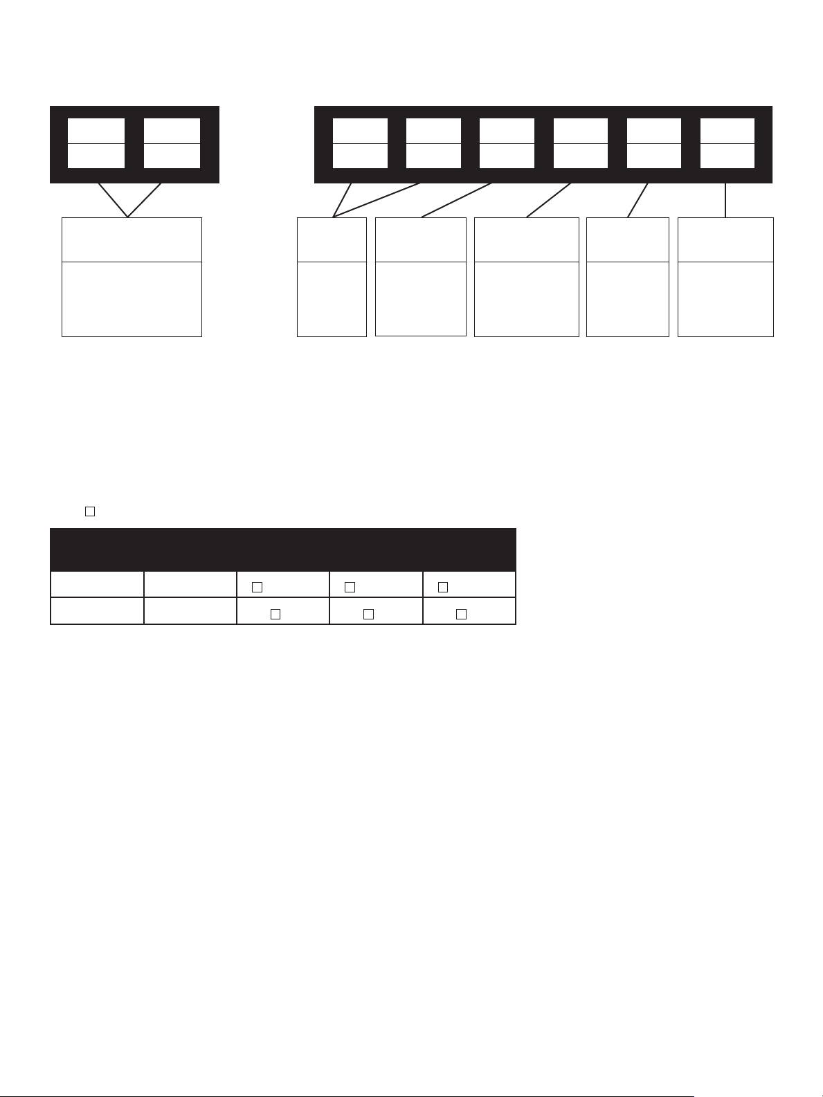
Numbering System
1st 2nd 1st 2nd 3rd 4th 5th 6th
8 8 0 3 8
Actuator Type
87 Spring Diaphragm
Air to Extend
88 Spring Diaphragm
Air to Retract
—
—
Body
Series
80
Plug Type
3. Top and
Ratings/Connections
Flanged n Butt Weld ∆ RT Joint l Threaded m Socket Weld
Valve Sizes ASME Class
inches mm 150 300 600
Port
Guided
Control
Characteristics
8. Linear
Ported
Seat Type
5. Combing
Design
5. Diverting
Design
Optional
Configuration
EB Extension
Bonnet
.75, 1, 1.5, 2 20, 25, 40, 50
3 through 12 80 through 300
1) .75” & 1” (20mm & 25mm) sizes not available in 80386 version - Diverting Design Utilize combining
design and consult factory for details.
2) Welded end connections, other flanged configurations, and ASME ratings above 600 Class are
available upon request. Consult factory for details.
l ∆ m l ∆ m l ∆ m
∆ ∆ ∆
4 | GE Oil & Gas
Page 5

General Data
Body
Type: 3-way
Flow Direction: Flow to open (both ports)
CV Ratio: 50:1
Materials: Carbon steel
Stainless steel
Chrome-molybdenum steel
Others
Bonnet
Type: Bolted
Packing Box: Bolted
Optional: Extension
Materials: Carbon steel
Stainless steel
Chrome-molybdenum steel
Others
Trim
Type: 385 - combining
386 - diverting
Flow Characteristics
Linear
Full capacity only
Actuator
Actuator
Type: Spring diaphragm
Direct, air to extend
Reverse, air to retract
CH80000 - 80000 Series Three-Way Control Valves | 5
Page 6
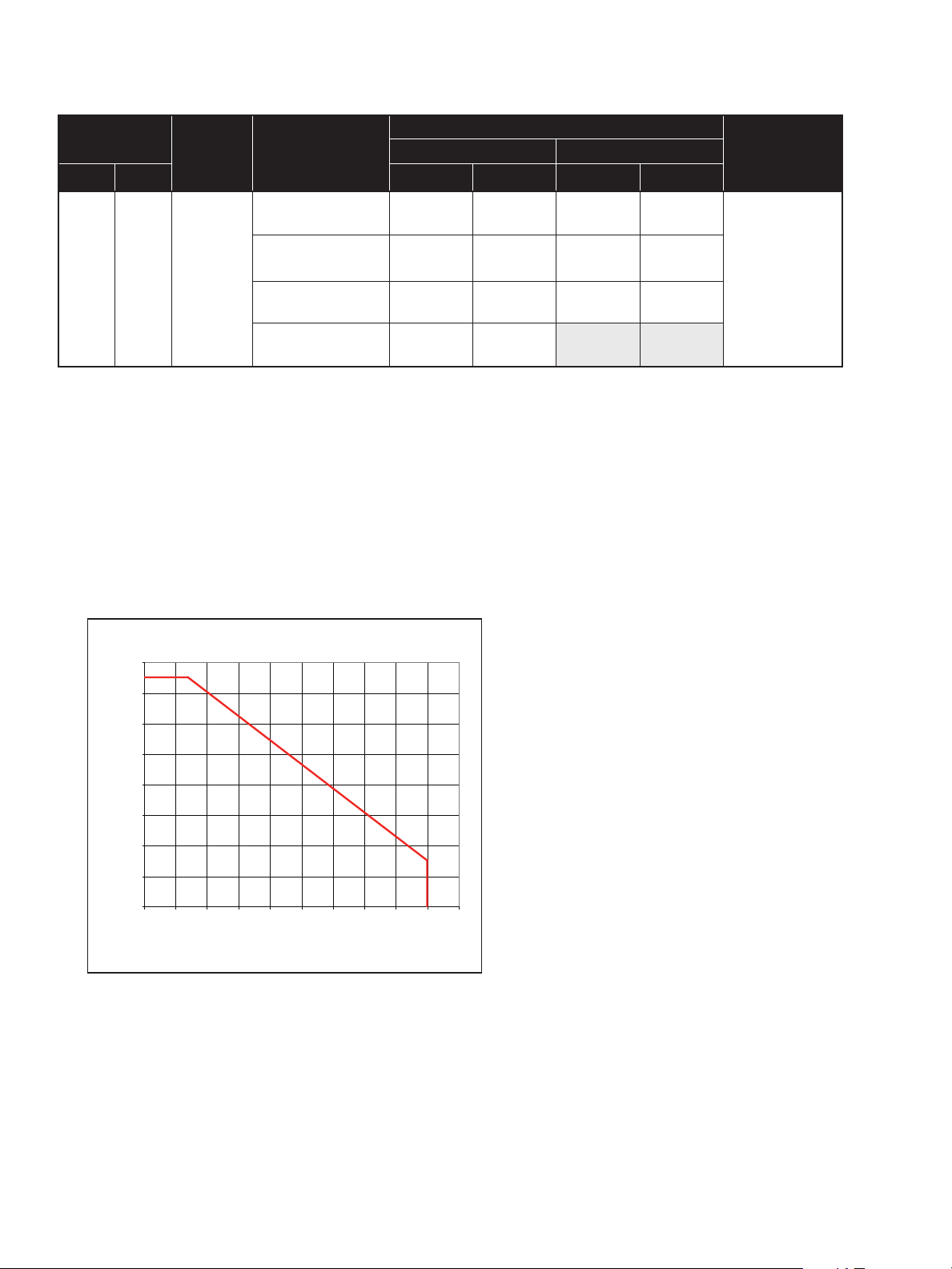
Temperature Range/Seat Leakage
-4°F
(-20°C)
-148 ° F
(-10 0 ° C )
1100°F
(594°C)
(1)
+800°F
(+427°C)
+800°F
(+427°C)
32°F
(0°C)
Temperature Ranges
(2)
+450°F
(+232°C)
(2)
+450°F
(+232°C)
(2)
+450°F
(+232°C)
(2)
+450°F
(+232°C)
20
to
300
(1)
Body
Rating
ASME
Class 150
to 600 (PN
10 to 100)
Body & Bonnet
Material
Carbon
Steel
Stainless
Steel
Chrome-Moly
NACE
Standard Bonnet Extension Bonnet
Min. Max. Min. Max.
-4°F
(-20°C)
-20°F
(-29°C)
32°F
(0°C)
-4°F
(-20°C)
Value Size
inch mm
0.75
to
12
1) .75” & 1” (20 & 25mm) sizes are not available in the 80386 diverting configuration.
Utilize combining version 80385 and consult factory for details.
2) Maximum temperature shown is with PTFE and LE packing. Extended max. operating temperature of 800°F (427°C)
allowable with Graphite packing.
3) Class II shutoff is standard leakage rating. Class III and IV can be provided depending on application service conditions.
Consult with factory on Class III and IV applications and requirements.
4) LE Packing for low emissions applications is limited to maximum pressure and temperature as shown in chart below.
Seat Leakage
IEC 60534-4
and ANSI/FCI
70.2 Class
(3)
II, III,
or IV
Pressure and Temperature Rating of LE Packing
1600
(112)
1400
(98)
1200
(84)
1000
(70)
800
(56)
600
(42)
400
Fluid Pressure PSI (Bar)
(28)
200
(14)
0
0 50 100 150 200 250 300 350 400 450 500
(10) (38) (66) (93) (121) (149) (177) (204) (232) (260)
Fluid Temperature °F (°C)
(4)
6 | GE Oil & Gas
Page 7
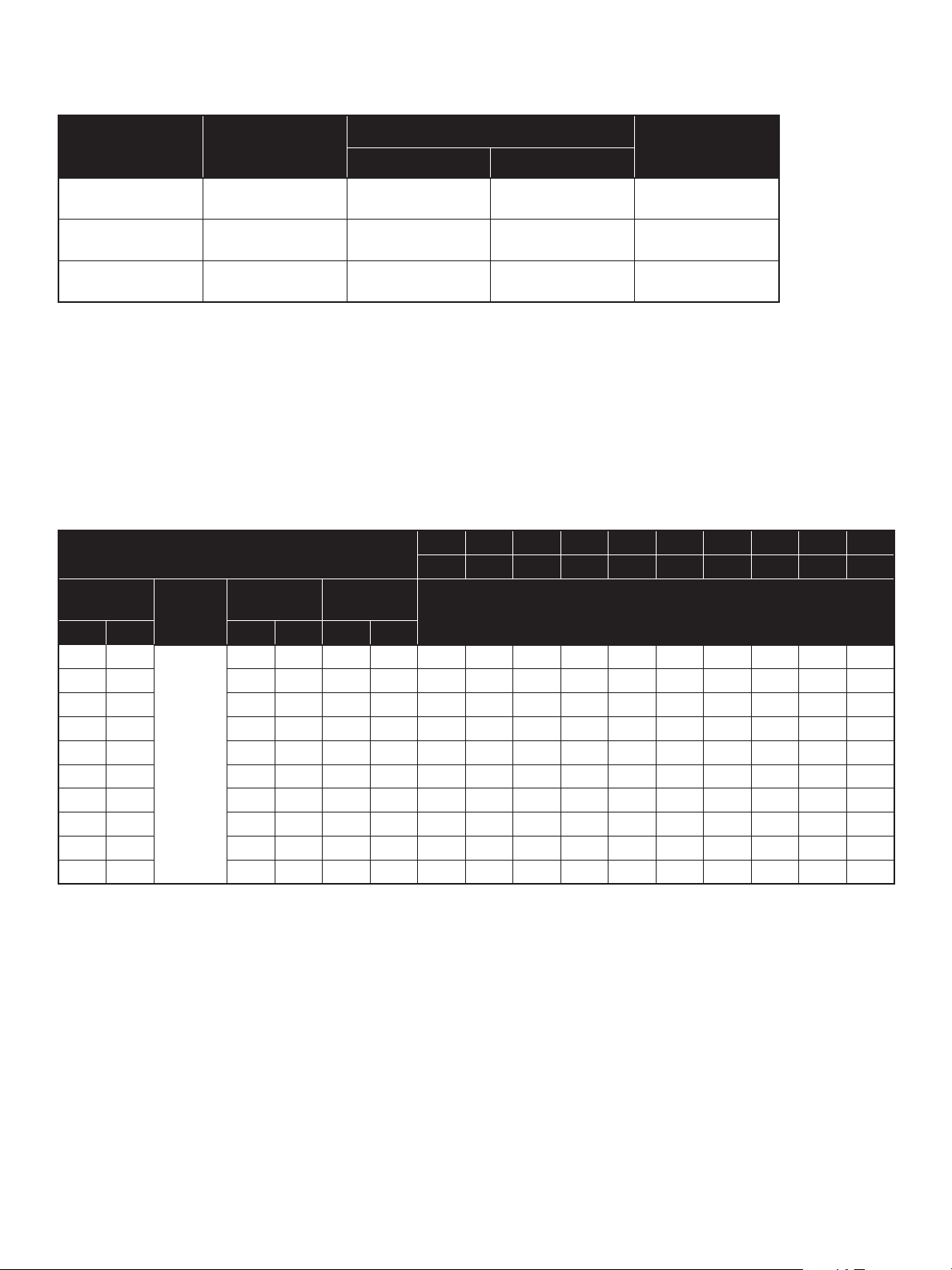
Flow Direction & Application
Valve Model Type of Service
inches mm
80385 Combining .75 to 12 20 to 300 FTO
80385* Diverting .75 & 1 20 & 25 FTC
80386 Diverting 1.5 to 12 40 to 300 FTO
* .75” & 1” (20 & 25mm) sizes are not available in the 80386 diverting configuration.
Utilize combining version 80385 and consult factory for details.
Valve Size
CV and FL versus Travel
Percent of Travel 10 20 30 40 50 60 70 80 90 100
F
L
Value Size
inch mm inch mm inch mm
75 20
1 25 1.06 26.9 .05 12.7 0.9 1.8 2.7 3.6 4.5 5.4 6.3 7.2 8.1 9
1.5 40 1.5 38.1 .08 20.3 2.1 4.2 6.3 8.4 10.5 12.6 14.7 16.8 18.9 21
2 50 2.00 50.8 .08 20.3 3.6 7. 2 10.8 14.4 18 21.6 25.2 28.8 32.4 36
3 80 2.62 66.5 1.5 38.1 7. 5 15 22.5 30 37.5 45 52.5 60 67.5 75
4 100 3.50 88.9 1.5 38.1 12.4 24.8 37.2 49.6 62 74.4 86.8 99.2 112 124
6 150 5.25 133 2.0 50.8 27 54 81 108 135 162 189 216 243 270
8 200 7.0 0 178 2.5 63.5 48 96 144 192 240 288 336 384 432 480
10 250 8.75 22 2.5 63.5 75 150 225 300 375 450 525 600 675 750
(1)
300 10.5 267 3.5 88.9 108 216 324 432 540 648 756 864 972 1080
12
ASME
Rating
150 to
600
Orifice
Diameter
.88 22.3 .05 12.7 0.6 1.2 1.8 2.4 3 3.6 4.2 4.8 5.4 6
Travel
0.90 0.91 0.91 0.92 0.92 0.92 0.91 0.91 0.90 0.90
Flow Direction
(Both Ports)
Rated C
Direction: FLOW-TO-OPEN (FTO)
Flow Characteristic: LINEAR
V
1) Use spring-diaphragm actuator Model 37/38 for 12” (300 mm) valve size.
CH80000 - 80000 Series Three-Way Control Valves | 7
Page 8
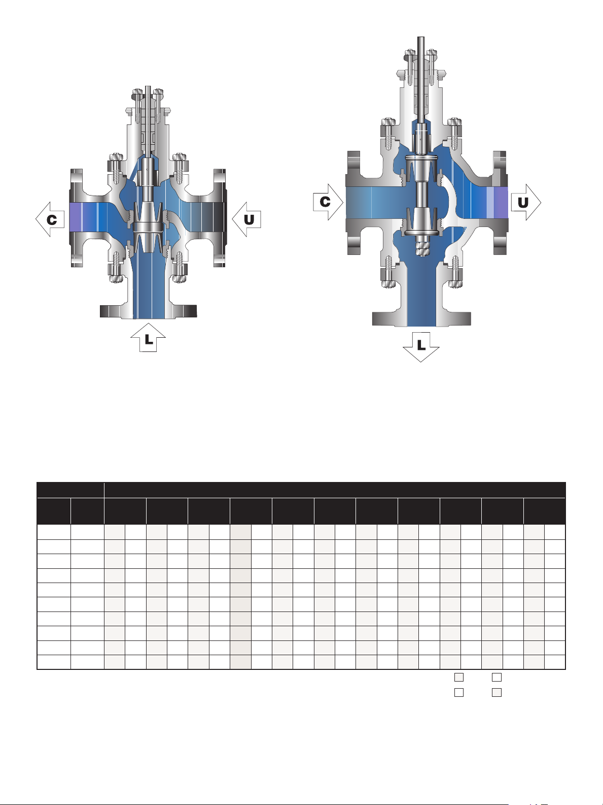
CV and Flow Direction
80385 Combining
80386 Diverting
C = Common L = Lower U = Upper
Body Ratings: ANSI Class 150 through 600 (PN 10 to 100)
Sizes: *.75” through 12” (20mm through 300mm)
Flow Direction: flow to open (both ports)
Flow Characteristic: linear
0% - Plug in Up Position
100% - Plug in Down Position
Value Size* Percent of Plug Travel
Plug Up
inches mm
.75 20 0 6 0.6 5.4 1.2 4.8 1.8 4.2 2.4 3.6 3 3 3.6 2.4 4.2 1.8 4.8 1.2 5.4 0.6 6 0
1 25 0 9 0.9 8.1 1.8 7. 2 2.7 6.3 3.6 5.4 4.5 4.5 5.4 3.6 6.3 2.7 7.2 1.8 8.1 0.9 9 0
1.5 40 0 21 2.1 18.9 4.2 16.8 6.3 14.7 8.4 12.6 10.5 10.5 12.6 8.4 14.7 6.3 16.8 4.2 18.9 2.1 21 0
2 50 0 36 3.6 32.4 7. 2 28.8 10.8 25.2 14.4 21.6 18.0 18.0 21.6 14.4 25.5 10.8 28.8 7.2 32.4 3.6 36 0
3 80 0 75 7. 5 67. 5 15 60 22.5 52.5 30 45 37.5 37.5 45 30 52.5 22.5 60 15 6 7. 5 7.5 75 0
4 100 0 124 12.4 111.6 24.8 99.2 37. 2 86.8 49.6 74.4 62 62 74.4 49.6 86.8 37. 2 99.2 24.8 111.6 12.4 124 0
6 150 0 270 27 243 54 216 81 189 108 162 135 135 162 108 189 81 216 54 243 27 270 0
8 200 0 480 48 432 96 384 144 336 192 288 240 240 288 192 336 144 384 96 432 48 480 0
10 250 0 750 75 675 150 600 225 525 300 450 375 375 450 300 525 225 600 150 675 75 750 0
12 300 0 1080 108 972 216 864 324 756 432 648 540 540 648 432 756 324 864 216 972 108 1080 0
* 1” (25mm) size not available in 80386 version - Diverting Design.
Utilize combining design and consult factory for details.
0% 10% 20% 30% 40% 50% 60% 70% 80% 90%
80385 U to C L to C
80386 U to C L to C
Plug Down
100%
8 | GE Oil & Gas
Page 9

Materials of Construction
4 3 2
19
5
17
18
7
13
14
9
16
15
1
12
11
8
4 3 2
19
5
17
18
7
13
14
9
16
15
1
12
11
8
6
10
111213
13
80385 Combining 80386 Diverting
9C9B9A 9D
6
10
1112
CH80000 - 80000 Series Three-Way Control Valves | 9
Page 10

Materials of Construction
Standard Carbon Steel Version
Ref. No.
1 Plug Stem 316 St. St. ASTM 479 TY 316
2 Packing Flange Nut St. St. ASTM A194 GR 8
3 Packing Flange Zinc Dichromate Carbon Steel ASTM A105
4 Packing Flange Stud 304 St. St. ASTM A193 GR B8
5 Drive Nut Carbon Steel SAE 1117 or ASTM A216 GR WCC
6 Valve Bonnet Carbon Steel ASTM A216 Grade WCC or ASTM A105
7 Valve Body Carbon Steel ASTM A216 Grade WCC
8 Plug Pin 316 St. St. ASTM 479 TY 316
9
10 Lower Flange Carbon Steel ASTM A216 Grade WCC or ASTM A105
11 Body Stud Nut Carbon Steel ASTM A194 GR 2H
12 Body Stud Alloy Steel ASTM A193 GR B7
13 Body Gasket 316L St. St. w/Flexible Graphite Filler (Spiral Wound)
14 Guide Bushing 440C St. St. ASTM A276 TY 440C Stellite or Equivalent 6 UNS 30006
15 Lower Seat Ring
16 Upper Seat Ring
18 Lantern Ring (Optional) Austenitic 300 Series Stainless Steel
19 Packing Follower Austenitic 300 Series Stainless Steel
Ref. No. Temperature Range -20°C 343°C 427°C
Temperature Range
Description Materials
Plug
9A - Upper Skirt
9B - Plug Gasket
9C - Lower Skirt
9D - Jam Nuts
(1)
(1)
(1)
(1)
-4°F 650°F 850°F
316 St. St. ASTM 479 TY 316
316 St.St.with Hardfaced Seat
316 St. St. ASTM 479 TY 316
316 St.St.with Hardfaced Seat
316 St. St. ASTM 479 TY 316
316 St. St. ASTM 479 TY 316
316 St.St.with Hardfaced Seat
ASTM A194 GR 8M
316 St. St. ASTM 479 TY 316
316 St.St. with Hardfaced Seat
316 St. St. ASTM 479 TY 316
316 St.St. with Hardfaced Seat
Valve Sizes: 0.75” to 12” (20mm to 300mm)
Body Ratings: ASME Class 150 to 600
316 St. St. with Hardfaced
Seat and Guide
316 St. St. with
Hardfaced Seat
316 St. St. with
Hardfaced Seat
316 St. St. with
Hardfaced Seat
316 St. St. with
Hardfaced Seat
(2)
1) Separate plug components only required for Model 80386.
2) Hardfaced bushings and plug guiding surfaces are required for temperatures above 650°F (343°C).
10 | GE Oil & Gas
Page 11

Materials of Construction
Standard Carbon Steel Version
Ref. No.
1 Plug Stem 316 St. St. ASTM 479 TY 316
2 Packing Flange Nut St. St. ASTM A194 GR 8
3 Packing Flange Zinc Dichromate Carbon Steel ASTM A105
4 Packing Flange Stud 304 St. St. ASTM A193 GR B8
5 Drive Nut Carbon Steel SAE 1117 or ASTM A216 GR WCC
6
7 Valve Body 316 Stainless Steel ASTM A351 Grade CF8M
8 Plug Pin 316 St. St. ASTM 479 TY 316
9
Temperature Range
Description Materials
Valve Bonnet
Plain Version
Valve Bonnet
Extended Version
Plug
9A - Upper Skirt
9B - Plug Gasket
9C - Lower Skirt
9D - Jam Nuts
(1)
(1)
(1)
(1)
-148°F -20°F 650°F 850°F
316 Stainless Steel ASTM A351 Grade CF8M or ASTM A182 Grade F316
316 Stainless Steel ASTM A351 Grade CF8M or ASTM A182 Grade F316
316 St. St. ASTM 479 TY 316
316 St.St.with Hardfaced Seat
316 St. St. ASTM 479 TY 316
316 St.St.with Hardfaced Seat
316 St. St. ASTM 479 TY 316
316 St. St. ASTM 479 TY 316
316 St.St.with Hardfaced Seat
ASTM A194 GR 8M
Valve Sizes: 0.75” to 12” (20mm to 300mm)
Body Ratings: ASME Class 150 to 600
316 St. St. with Hardfaced
Seat and Guide
316 St. St. with
Hardfaced Seat
316 St. St. with
Hardfaced Seat
10 Lower Flange 316 Stainless Steel ASTM A351 Grade CF8M or ASTM A182 Grade F316
Carbon Steel ASTM A194 GR 2H
11 Body Stud Nut
ASTM A194 Gr. 8
12 Body Stud
ASTM A193 Gr. B8
13 Body Gasket 316L St. St. w/Flexible Graphite Filler (Spiral Wound)
14 Guide Bushing Stellite or Equivalent 6(3)
15 Lower Seat Ring
16 Upper Seat Ring
18 Lantern Ring (Optional) Austenitic 300 Series Stainless Steel
19 Packing Follower Austenitic 300 Series Stainless Steel
Ref. No. Temperature Range -100°C -29°C 343°C 427°C
1) Separate plug components only required for Model 80386.
2) ASTM A453 Gr. 660 Body Studs may be required for low temperature applications or for corrosion resistance requirements.
3) Solid Stellite or Equivalent bushings are tack welded in bonnet and lower flange for applications above 650°F (343°C) to account for
thermal expansion.
316 St. St. ASTM 479 TY 316
316 St.St. with Hardfaced Seat
316 St. St. ASTM 479 TY 316
316 St.St. with Hardfaced Seat
Zinc Dichromate Plating
Alloy Steel ASTM A193 GR B7
Zinc Dichromate Plating
(2)
C. S. ASTM A194 GR 2H
(No Zinc)
Alloy Steel ASTM A193
GR B7
316 St. St. with
Hardfaced Seat
316 St. St. with
Hardfaced Seat
CH80000 - 80000 Series Three-Way Control Valves | 11
Page 12

Materials of Construction
Standard Chrome Moly Version
Ref. No.
1 Plug Stem 316 St. St. ASTM 479 TY 316
2 Packing Flange Nut St. St. ASTM A194 GR 8
3 Packing Flange Zinc Dichromate Carbon Steel ASTM A105
4 Packing Flange Stud 304 St. St. ASTM A193 GR B8
5 Drive Nut Carbon Steel SAE 1117 or ASTM A216 GR WCC
6 Valve Bonnet Chrome-Molybdenum Steel ASTM A217 Grade WC9
7 Valve Body Chrome-Molybdenum Steel ASTM A217 Grade WC9
8 Plug Pin 316 St. St. ASTM 479 TY 316
9
10 Lower Flange Chrome-Molybdenum Steel ASTM A217 Grade WC9
11 Body Stud Nut Carbon Steel ASTM A194 GR 2H
12 Body Stud Alloy Steel ASTM A193 GR B7
13 Body Gasket 316L St. St. w/Flexible Graphite Filler (Spiral Wound)
14 Guide Bushing 440C St. St. ASTM A276 TY 440C Stellite or Equivalent 6 UNS 30006
15 Lower Seat Ring
16 Upper Seat Ring
18 Lantern Ring (Optional) Austenitic 300 Series Stainless Steel
19 Packing Follower Austenitic 300 Series Stainless Steel
Ref. No. Temperature Range 0°C 343°C 427°C
Temperature Range
Description Materials
Plug
9A - Upper Skirt
9B - Plug Gasket
9C - Lower Skirt
9D - Jam Nuts
(1)
(1)
(1)
(1)
-32°F 650°F 800°F
316 St. St. ASTM 479 TY 316
316 St.St.with Hardfaced Seat
316 St. St. ASTM 479 TY 316
316 St. St. with Hardfaced Seat
316 St. St. ASTM 479 TY 316
316 St. St. ASTM 479 TY 316
316 St.St.with Hardfaced Seat
ASTM A194 GR 8M
316 St. St. ASTM 479 TY 316
316 St.St. with Hardfaced Seat
316 St. St. ASTM 479 TY 316
316 St. St. with Hardfaced Seat
Valve Sizes: 0.75” to 12” (20mm to 300mm)
Body Ratings: ASME Class 150 to 600
316 St. St. with Hardfaced
Seat and Guide
316 St. St. with
Hardfaced Seat
316 St. St. with
Hardfaced Seat
316 St. St. with
Hardfaced Seat
316 St. St. with
Hardfaced Seat
(2)
1) Separate plug components only required for Model 80386.
2) Hardfaced bushings and plug guiding surfaces are required for temperatures above 650°F (343°C).
12 | GE Oil & Gas
Page 13

Materials of Construction
Standard Packing Options
Ref. No.
17
Ref. No. Temperature Range -29°C 232°C 427°C
Temperature Range
Description Materials
Packing
Packing
Standard
Bonnet
Standard
Bonnet
-20°F 450°F 800°F
PTFE Packing
®
LE
Packing
Flexible Graphite Packing
PTFE Packing
®
Packing
LE
Flexible Graphite Packing
Valve Sizes: 0.75” to 12” (20mm to 300mm)
Body Ratings: ASME Class 150 to 600
CH80000 - 80000 Series Three-Way Control Valves | 13
Page 14

Materials of Construction
Standard NACE Version
Ref. No.
1 Plug Stem
2 Packing Flange Nut
Temperature Range
Description Standard Operating Materials
-20°F 450°F
316 St. St. ASTM A479 TY 316 (HRC 22 Max.)
ASTM A638 Gr 660
304 St. St. ASTM A194 Gr 8
Alloy Steel ASTM A194 Gr 8A
(2)
(3)
(non exposed)
(4)
(exposed)
Body Ratings: ASME Class 150 to 600
(1)
3 Packing Flange Zinc Dichromate Carbon Steel ASTM A105
4 Packing Flange Stud 304 St. St. ASTM A193 GR B8 (exposed and non exposed)
Valve Sizes: 0.75” to 12” (20mm to 300mm)
(3)
(4)
5 Drive Nut
Carbon Steel SAE 1117
Carbon Steel ASTM A105 or SAE 1010-1025
Carbon Steel ASTM A216 Grade WCC (HRC 22 Max.)
6 Valve Bonnet
Carbon Steel ASTM A105 (HRC 22 Max.)
316 St. St. ASTM A351 Gr CF8M (HRC 22 Max.)
7 Valve Body
Carbon Steel ASTM A216 Grade WCC (HRC 22 Max.)
316 St. St. ASTM A351 Gr CF8M (HRC 22 Max.)
8 Plug Pin 316 St. St. ASTM A479 TY 316 (HRC 22 Max.)
Plug
9A - Upper Skirt
9
9B - Plug Gasket
9C - Lower Skirt
9D - Jam Nuts
(6)
(6)
(6)
(6)
316 St. St. ASTM A479 TY 316 (HRC 22 Max.)
316 St. St. ASTM A479 TY 316 with Hardfaced Seat (HRC 22 Max.)
316 St. St. ASTM A479 TY 316 (HRC 22 Max.)
316 St. St. ASTM A479 TY 316 with Hardfaced Seat (HRC 22 Max.)
316 St. St. ASTM A479 TY 316 (HRC 22 Max.)
316 St. St. ASTM A479 TY 316 (HRC 22 Max.)
316 St. St. ASTM A479 TY 316 with Hardfaced Seat (HRC 22 Max.)
ASTM A194 Gr. 8M
Carbon Steel ASTM A216 Grade WCC (HRC 22 Max.)
Carbon Steel ASTM A105 (HRC 22 Max.)
10 Lower Flange
11 Body Stud Nut
316 St. St. ASTM A351 Gr CF8M (HRC 22 Max.)
(3)(5)
ASTM A194 GR 2H Zinc Plating
ASTM A194 Gr 2HM Zinc Plating
(3)
ASTM A194 GR 2H
ASTM A194 Gr 2HM
(non exposed)
(4)
(exposed)
(non exposed)
(4)(5)
(exposed)
Ref. No. Temperature Range -29°C 232°C
14 | GE Oil & Gas
Page 15

Materials of Construction
Standard NACE Version
Ref. No.
12 Body Stud
13 Body Gasket 316L St. St. w/Flexible Graphite Filler (Spiral Wound)
14 Guide Bushing Stellite or Equivalent 6 UNS 30006
15 Lower Seat Ring
16 Upper Seat Ring
17 Packing PTFE (Teflon)
18 Lantern Ring (Optional) 304 St. St. ASTM A479 TY 304
19 Packing Follower 304 St. St. ASTM A479 TY 304
Ref. No. Temperature Range -29°C 232°C
1) Materials and processes in accordance with the requirements of NACE specification MR0103, 2003.
Applications requiring compliance to MR0175, 2003 Rev. or ISO 15156 requires factory review.
2) ASTM A638 Gr. 660 Stem option will be substituted in applications as required based on operating pressure conditions.
3) Materials designated for these parts conform to NACE Class III (unexposed) bolting requirements.
4) Materials designated for these parts conform to NACE Class I or Class II (exposed) bolting requirements.
5) Zinc plating is mandatory for St. Steel construction only.
6) Separate plug components only required for Model 80386.
Temperature Range
Description Standard Operating Materials
-20°F 450°F
(3)
ASTM A193 GR B7
ASTM A193 Gr B7M
ASTM A193 GR B7 Zinc Plating
ASTM A193 Gr B7M Zinc Plating
316 St. St. ASTM A479 TY 316 (HRC 22 Max.)
316 St. St. ASTM A479 TY 316 with Hardfaced Seat (HRC 22 Max.)
316 St. St. ASTM A479 TY 316 (HRC 22 Max.)
316 St. St. ASTM A479 TY 316 with Hardfaced Seat (HRC 22 Max.)
(non exposed)
(4)
(exposed)
(3)(5)
(4)(5)
(non exposed)
(exposed)
Valve Sizes: 0.75” to 12” (20mm to 300mm)
Body Ratings: ASME Class 150 to 600
(1)
CH80000 - 80000 Series Three-Way Control Valves | 15
Page 16

Valve Dimensions
80385 Series Dimensions (inches)
D
E
C
B
F
A
Valve Size
inches mm
.75 20 7.24 5.51 7.76 5.51 7.64 5.51 8.11 5.51 8.11 5.51 8.11 5.51 5.98 5.55
1 25 7.24 5.51 7.76 5.51 7.76 5.51 8.27 5.51 8.27 5.51 8.27 5.51 5.98 5.55
1.5 40 8.74 6.26 9.25 6.26 9.25 6.26 9.76 6.26 9.88 6.26 9.88 6.26 7.99 6.26
2 50 10.00 6.61 10.51 6.61 10.51 6.61 11.10 6.61 11.26 6.61 11.38 6.61 9.25 6.61
3 80 11.73 7.99 12.24 8.62 12.52 7.99 13.11 8.62 13.27 8.62 13.39 8.62
4 100 13.90 9.02 14.37 10.12 14.49 9.02 15.12 10.12 15.51 10.12 15.63 10.12
6 150 17.76 11.38 18.11 11.69 18.62 11.38 19.25 11.69 20.00 12.36 20.12 12.36
8 200 21.38 13.27 21.89 13.54 22.36 13.27 22.99 13.54 24.02 14.25 24.13 4.25
10 250 24.61 15.39 24.33 15.71 26.02 15.39 26.65 16.97 27.76 17.60 27.87 17.60
12 300 28.78 17.91 29.25 17.91 30.28 17.91 30.87 17.91 32.01 21.06 32.13 21.06
inches mm C (Std. Bonnet) C (EB Bonnet) F
.75 20 5.12 9.17
1 25 5.12 9.17
1.5 40 5.24 9.88
2 50 6.26 10.47
3 80 7.99 11.81
4 100 8.39 12.64
6 150 10.98 16.42
8 200 12.64 17.95
10 250 13.11 19.29
12 300 16.73 22.91
1) For Model 80385 - Dimension F is equal to one-half dimension A.
ASME Class 150 and
equivalent PN
RF RTJ RF RTJ RF RTJ
A B A B A B A B A B A B A B
Valve Size ASME Class 150 – 600 and equivalent PN
ASME Class 300 and
equivalent PN
ASME Class 600 and
equivalent PN
ANSI Class
150-600 and
equivalent PN
Threaded &
Socket Weld
See Note 1
16 | GE Oil & Gas
Page 17

80385 Series Dimensions (mm)
Valve Size
mm inches
20 .75 184 140 197 140 194 140 206 140 206 140 206 140 152 141
25 1 184 140 197 140 197 140 210 140 210 140 210 140 152 141
40 1.5 222 159 235 159 235 159 248 159 251 159 251 159 203 159
50 2 254 168 267 168 267 168 282 168 286 168 289 168 235 168
80 3 298 203 311 219 318 203 333 219 337 219 340 219
100 4 353 229 365 257 368 229 384 257 394 257 397 257
150 6 451 289 460 297 473 289 489 297 508 314 511 314
200 8 543 337 556 344 568 337 584 344 610 362 613 362
250 10 625 391 618 399 661 391 677 431 705 447 708 447
300 12 731 455 743 455 769 455 784 455 813 535 816 535
mm inches C (Std. Bonnet) C (EB Bonnet) F
20 .75 130 233
25 1 130 233
40 1.5 133 251
50 2 159 266
80 3 203 300
100 4 213 312
150 6 279 417
200 8 321 456
250 10 333 490
300 12 425 582
1) For Model 80385 - Dimension F is equal to one-half dimension A.
ASME Class 150 and
equivalent PN
RF RTJ RF RTJ RF RTJ
A B A B A B A B A B A B A B
Valve Size ASME Class 150 – 600 and equivalent PN
ASME Class 300 and
equivalent PN
ASME Class 600 and
equivalent PN
ANSI Class
150-600 and
equivalent PN
Threaded &
Socket Weld
See Note 1
CH80000 - 80000 Series Three-Way Control Valves | 17
Page 18

Valve Dimensions
80386 Series Dimensions (inches)
Valve Size
inches mm
.75 20 7.24 5.51 7.76 5.51 7.64 5.51 8.11 5.51 8.11 5.51 8.11 5.51 5.98 5.55
1 25 7.24 5.51 7.76 5.51 7.76 5.51 8.27 5.51 8.27 5.51 8.27 5.51 5.98 5.55
1.5 40 8.74 7.01 9.25 7.01 9.25 7.01 9.76 7.01 9.88 7.01 9.88 7.01 7.99 6.26
2 50 10.00 7.76 10.51 7.76 10.51 7.76 11.10 7.76 11.26 7.76 11.38 7.76 9.25 6.61
3 80 11.73 9.37 12.24 9.88 12.52 9.37 13.19 20.51 13.27 9.88 13.39 9.88
4 100 13.90 10.63 14.41 11.50 14.49 10.63 15.16 11.50 15.51 11.10 15.67 11.50
6 150 17.76 12.99 18.31 13.31 18.62 12.99 19.29 13.31 20.00 14.02 20.16 13.98
8 200 21.38 15.39 21.93 15.67 22.36 15.39 23.03 15.67 24.02 16.38 24.17 16.38
10 250 24.65 17.99 25.12 18.31 26.02 17.99 26.65 18.31 27.76 20.79 27.87 20.79
12 300 28.78 22.05 29.25 22.05 30.28 22.05 30.87 12.05 32.01 25.20 32.13 25.20
Valve Size
inches mm
.75 20 5.12 9.17
1 25 5.12 9.17
1.5 40 6.10 10.75 3.70 4.06 4.66 4.29 4.57 4.65 4.65
2 50 7.24 11.46 4.13 4.65 4.92 4.88 5.20 2.24 5.35
3 80 9.25 13.07 5.51 5.79 5.51 6.22 5.51 6.34
4 100 9.37 13.62 6.57 6.85 6.89 7.20 7.36 7.48
6 150 12.64 18.07 7.64 7.91 8.07 8.39 8.74 8.82
8 200 14.76 20.08 8.54 8.82 9.06 9.41 9.88 9.96
10 250 16.38 22.56 10.00 10.24 10.67 10.98 11.54 11.61
12 300 20.87 27.05 11.34 11.57 12.09 12.36 12.95 12.99
1) .75” & 1” (20 & 25mm) sizes are not available in the 80386 diverting configuration.
Utilize combining version 80385 and consult factory for details.
ASME Class 150 and
equivalent PN
RF RTJ RF RTJ RF RTJ
A B A B A B A B A B A B A B
ASME Class 150 and
equivalent PN
Std.
Bonnet
C C F F F F F F F
EB Bonnet
ASME Class 300 and
equivalent PN
ANSI Class
150-600 and
equivalent
PN
Threaded &
Socket Weld
ASME Class 600 and
equivalent PN
ASME Class 150 and
equivalent PN
RF RTJ RF RTJ RF RTJ
ASME Class 300 and
equivalent PN
See Note 1
ASME Class 600 and
ANSI Class
150-600 and
equivalent PN
Threaded &
Socket Weld
equivalent PN
18 | GE Oil & Gas
Page 19

Valve Dimensions
80386 Series Dimensions (mm)
Valve Size
mm inches
20 0.75 184 140 197 140 194 140 206 140 206 140 206 140 152 141
25 1 184 140 197 140 197 140 210 140 210 140 210 140 152 141
40 1.5 222 178 235 178 235 178 248 178 251 178 251 178 203 159
50 2 254 197 267 197 267 197 282 197 286 197 289 197 235 168
80 3 298 238 311 251 318 238 335 521 337 251 340 251
100 4 353 270 366 292 368 270 385 292 394 282 398 292
150 6 451 330 465 338 473 330 490 338 508 356 512 355
200 8 543 391 557 398 568 391 585 398 610 416 614 416
250 10 626 457 638 465 661 457 677 465 705 528 708 528
300 12 731 560 743 560 769 560 784 560 813 640 816 640
Valve Size
mm inches
20 0.75 130 233
25 1 130 233
40 1.5 155 273 94 103 110 109 116 118 118
50 2 184 291 105 118 125 124 132 133 136
80 3 235 332 140 147 140 158 140 161
100 4 238 346 167 174 175 183 187 190
150 6 321 459 194 201 205 213 222 224
200 8 375 510 217 224 230 239 251 253
250 10 416 573 254 260 271 279 293 295
300 12 530 687 288 294 307 314 329 330
1) .75” & 1” (20 & 25mm) sizes are not available in the 80386 diverting configuration.
Utilize combining version 80385 and consult factory for details.
ASME Class 150 and
equivalent PN
RF RTJ RF RTJ RF RTJ
A B A B A B A B A B A B A B
ASME Class 150 and
equivalent PN
Std.
Bonnet
C C F F F F F F F
EB Bonnet
ASME Class 300 and
equivalent PN
ANSI Class
150-600 and
equivalent
PN
Threaded &
Socket Weld
ASME Class 600 and
equivalent PN
ASME Class 150 and
equivalent PN
RF RTJ RF RTJ RF RTJ
ASME Class 300 and
equivalent PN
See Note 1
ASME Class 600 and
ANSI Class
150-600 and
equivalent PN
Threaded &
Socket Weld
equivalent PN
CH80000 - 80000 Series Three-Way Control Valves | 19
Page 20

Valve Weights
Body Sub-Assembly with Standard Bonnet (lbs)
Valve Size
inches mm Threaded & Socket Weld Flanged
0.75 20 33 44 44 70
1 25 33 44 44 70
1.5 40 88 90 90 99
2 50 123 125 125 139
3 80 207 220 220 233
4 100 273 299 299 328
6 150 504 524 524 614
8 200 693 772 772 933
10 250 1351 1714 1714 2083
12 300 1683 2875 2875 3522
ANSI Class 150-600
and equivalent PN
ASME Class 150 and
equivalent PN
ASME Class 300 and
equivalent PN
ASME Class 600 and
Body Sub-Assembly with Standard Bonnet (kg)
Valve Size
ANSI Class 150-600
and equivalent PN
ASME Class 150 and
equivalent PN
ASME Class 300 and
equivalent PN
ASME Class 600 and
equivalent PN
equivalent PN
mm inches Threaded & Socket Weld Flanged
20 0.75 15 20 20 32
25 1 15 20 20 32
40 1.5 40 41 41 45
50 2 56 57 57 63
80 3 94 100 100 106
100 4 124 136 136 149
150 6 229 238 238 279
200 8 315 351 351 424
250 10 614 779 779 947
300 12 765 1307 1307 1601
20 | GE Oil & Gas
Page 21

Actuator Dimensions and Weights (in./lbs)
XX
D
C
Shown with optional Handwheel
Dimensions and Weights
Actuator Size
A B (Model 88) C D Standard w/ Handwheel
6 11.50 15.54 (17.52) 10.00 9.00 45 60
10 10 14.50 19.58 (21.54) 10.90 12.00 85
16 16 18.75 28.22 (30.79) 14.00 18.00 210
23 23 21.63 30.71 (33.27) 16.00 18.00 265
Actuator Removal Clearance = 6 inches
Center of Gravity (inches)
Without Handwheel
Size X Y
6 .19 9.75
10 .0 12.88
16 .13 18.50
23 .06 21.13
With Handwheel
Size XX YY
6 1.25 9.13
10 0.88 12.00
16 1.38 16.75
23 1.38 19.00
Actuator Dimensions (inches) Weights (lbs.)
Limit Stops (inches)
Up Stop
Size Model Overall Height B
6
10 25.43
16 36.42
23 38.84
6
10 25.06
16 35.48
23 38.65
Down Stop
Size Model Overall Height B
6
10 25.98
16 37.20
23 39.90
6
10 25.85
16 37.46
23 40.33
87
88
87
88
19.45
19.16
19.80
19.74
YY
CH80000 - 80000 Series Three-Way Control Valves | 21
Page 22

Actuator Dimensions and Weights (mm/kg)
XX
D
C
Shown with optional Handwheel
Dimensions and Weights
Actuator Size
A B (Model 88) C D Standard w/ Handwheel
6 302 395 (445) 254 229 20 27
10 373 497 (547) 277 305 39 48
16 476 717 (782) 356 457 95 111
23 549 780 (845) 406 457 120 145
Actuator Removal Clearance = 152 mm
Center of Gravity (mm)
Without Handwheel
Size X Y
6 5 248
10 0 327
16 3 470
23 2 537
With Handwheel
Size XX YY
6 32 232
10 22 305
16 35 425
23 35 483
Actuator Dimensions (mm) Weights (kg)
Limit Stops (mm)
Up Stop
Size Model Overall Height B
6
10 646
16 925
23 987
6
10 636
16 901
23 982
Down Stop
Size Model Overall Height B
6
10 660
16 945
23 1014
6
10 657
16 952
23 1024
87
88
87
88
494
487
503
501
YY
22 | GE Oil & Gas
Page 23

Accessories
Options:
• Extension Bonnets
• Environmental Capabilities (LE Packing)
• Lubricator & Isolation Valve
• Other Flange Facings
• Limit Stops
• Body Drain Plug
• Reducer and Nipple Connections
• NACE Compliance
• Custom Trim Materials
• U.O.P. Trim Materials
• Other Materials
• Non-Destructive Examination
• Oxygen Cleaning
• Electric Actuators
For Accessories, consult GE.
CH80000 - 80000 Series Three-Way Control Valves | 23
Page 24

DIRECT SALES OFFICE LOCATIONS
BELGIUM
Phone: +32-2-344-0970
Fax: +32-2-344-1123
BRAZIL
Phone: +55-11-2146-3600
Fax: +55-11-2146-3610
CHINA
Phone: +86-10-8486-4515
Fax: +86-10-8486-5305
FRANCE
Courbevoie
Phone: +33-1-4904-9000
Fax: +33-1-4904-9010
GERMANY
Ratingen
Phone: +49-2102-108-0
Fax: +49-2102-108-111
INDIA
Mumbai
Phone: +91-22-8354790
Fax: +91-22-8354791
New Delhi
Phone: +91-11-2-6164175
Fax: +91-11-5-1659635
ITALY
Phone: +39-081-7892-111
Fax: +39-081-7892-208
JAPAN Chiba
Phone: +81-43-297-9222
Fax: +81-43-299-1115
KOREA
Phone: +82-2-2274-0748
Fax: +82-2-2274-0794
MALAYSIA
Phone: +60-3-2161-0322
Fax: +60-3-2163-6312
MEXICO
Phone: +52-5-310-9863
Fax: +52-5-310-5584
THE NETHERLANDS
Phone: +0031-15-3808666
Fax: +0031-18-1641438
RUSSIA
Veliky Novgorod
Phone: +7-8162-55-7898
Fax: +7-8162-55-7921
Moscow
Phone: +7 495-585-1276
Fax: +7 495-585-1279
SAUDI ARABIA
Phone: +966-3-341-0278
Fax: +966-3-341-7624
SINGAPORE
Phone: +65-6861-6100
Fax: +65-6861-7172
SOUTH AFRICA
Phone: +27-11-452-1550
Fax: +27-11-452-6542
SOUTH and CENTRAL
AMERICA and the CARIBBEAN
Phone: +55-12-2134-1201
Fax: +55-12-2134-1238
SPAIN
Phone: +34-93-652-6430
Fax: +34-93-652-6444
UNITED ARAB EMIRATES
Phone: +971-4-8991-777
Fax: +971-4-8991-778
UNITED KINGDOM
Wooburn Green
Phone: +44-1628-536300
Fax: +44-1628-536319
UNITED STATES
Massachusetts
Phone: +1-508-586-4600
Fax: +1-508-427-8971
Corpus Christi, Texas
Phone: +1-361-881-8182
Fax: +1-361-881-8246
Deer Park, Texas
Phone: +1-281-884-1000
Fax: +1-281-884-1010
Houston, Texas
Phone: +1-281-671-1640
Fax: +1-281-671-1735
* Trademark of G eneral Elect ric Company
Other company names and product names used in this document are the registered trademarks
or trademarks of their respective owners.
© 2013 General El ectric Comp any. All rights r eserved.
GEA20199 05/2013
 Loading...