

Page 1
Not for
Reproduction
Generator Systems
30,000 Watt
Generator System
Model 076080
Operator’s Manual
This generator is rated in accordance with UL (Underwriters Laboratories) 2200 (stationary engine generator assemblies) and
CSA (Canadian Standards Association) standard C22.2 No. 100-4 (motors and generators).
Page 2

Not for
Reproduction
Thank you for purchasing this quality-built GE generator. We’re pleased that you’ve placed your confidence in the GE brand.
When operated and maintained according to the instructions in this manual, your generator will provide many years of
dependable service.
This manual contains safety information to make you aware of the hazards and risks associated with standby generators and
how to avoid them. Because we do not necessarily know all the applications this equipment could be used for, it is important
that you read and understand these instructions thoroughly before attempting to start or operate this equipment. Save these
instructions for future reference.
This generator requires professional installation before use. Refer to the separate installation manual for full information.
Your installer should follow the instructions completely.
Where to Find Us
You never have to look far to find GE support and service for your generator. For quick service when you need it, keep your
original receipt with this manual. You may contact Customer Service at 888‑575‑8226 between 8:00 AM and 5:00 PM CT, or click
on SERVICE & SUPPORT at www.standbygeneratorsystems.com, which provides a list of authorized dealers.
2
Page 3

Not for
Reproduction
Table of Contents
Safety Rules................................................4
Installation ................................................7
For the Owner................................................ 7
For the Installing Dealer/Contractor.................................... 7
Owner Orientation.................................................... 8
Fuel Factors..........................................................8
Generator Location ...................................................9
Delivery Inspection ...................................................9
Controls ..................................................10
Operation.................................................18
Automatic Operation ................................................18
Setting the Exercise Timer ............................................19
Maintenance ..............................................20
Service Code Detection System .......................................20
Generator Maintenance ..............................................22
Engine Oil...........................................................22
Synthetic Oils .......................................................22
Oil Recommendation.................................................23
Checking Engine Oil Level ............................................23
Engine Drive Belts ...................................................24
Engine Coolant System...............................................25
Engine Air Cleaner ..................................................25
Generator Electrical System Maintenance .............................26
Battery
Fuel System Inspection and Maintenance ..............................27
Storage.............................................................28
Troubleshooting ...........................................30
Warranty .................................................31
Product Specifications .....................................34
.................................................... 26
3
Page 4
Not for
Reproduction
Safety Rules
Important Safety Instructions
SAVE THESE INSTRUCTIONS - This manual contains
important instructions that should be followed during
installation and maintenance of the generator and batteries.
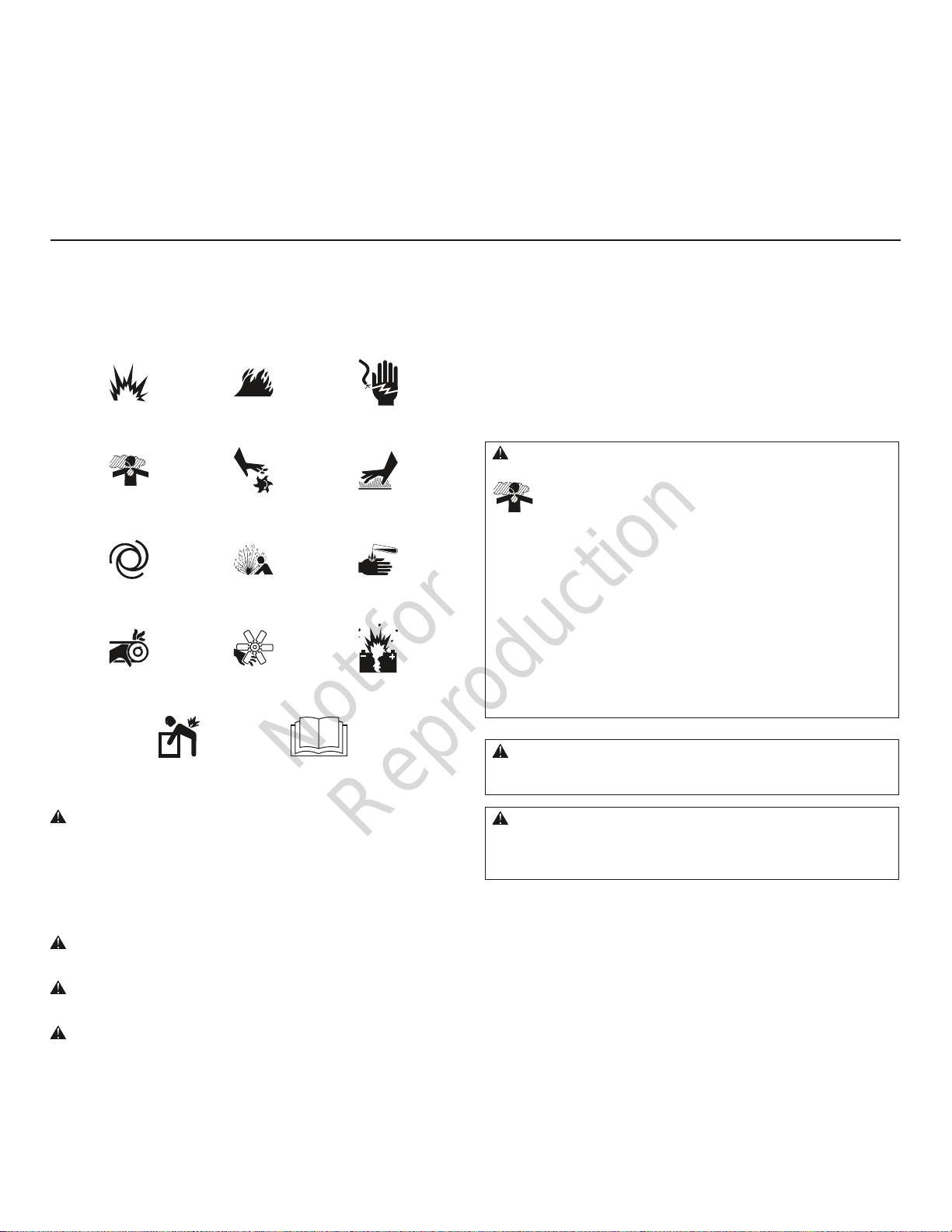
Safety Symbols and Meanings
Fire
Toxic Fumes
Explosive Pressure
Rotating Fan Blade
Electrical ShockExplosion
Hot SurfaceRotating Parts
Chemical BurnAuto Start
Exploding BatteryRotating Belt/Pulley
The manufacturer cannot possibly anticipate every possible
circumstance that might involve a hazard. The warnings
in this manual, and the tags and decals affixed to the unit
are, therefore, not all-inclusive. If you use a procedure, work
method or operating technique that the manufacturer does
not specifically recommend, you must satisfy yourself that it
is safe for you and others. You must also make sure that the
procedure, work method or operating technique that you
choose does not render the generator system unsafe.
WARNING Running engine gives off carbon monoxide, an
odorless, colorless, poison gas.
Breathing carbon monoxide could result in death, serious
injury, headache, fatigue, dizziness, vomiting, confusion,
seizures, nausea or fainting.
• Operate this product ONLY outdoors in an area that will not
accumulate deadly exhaust gas.
• Keep exhaust gas away from any windows, doors, ventilation
intakes, soffit vents, crawl spaces, open garage doors or other
openings that can allow exhaust gas to enter inside or be drawn
into a potentially occupied building or structure.
• Carbon monoxide detector(s) MUST be installed and maintained
indoors according to the manufacturer’s instructions/
recommendations. Smoke alarms cannot detect carbon
monoxide gas.
Lift Hazard Read Manual
The safety alert symbol indicates a potential personal
injury hazard. A signal word (DANGER, WARNING, or
CAUTION) is used with the alert symbol to designate a degree
or level of hazard seriousness. A safety symbol may be used
to represent the type of hazard. The signal word NOTICE is
used to address practices not related to personal injury.
DANGER indicates a hazard which, if not avoided, will
result in death or serious injury.
WARNING indicates a hazard which, if not avoided, could
result in death or serious injury.
CAUTION indicates a hazard which, if not avoided, could
result in minor or moderate injury.
NOTICE addresses practices not related to personal injury.
4
WARNING The engine exhaust from this product contains
chemicals known to the State of California to cause cancer, birth
defects, or other reproductive harm.
WARNING Certain components in this product and related
accessories contain chemicals known to the State of California
to cause cancer, birth defects, or other reproductive harm. Wash
hands after handling.
Page 5
Not for
Reproduction
WARNING Storage batteries give off explosive hydrogen gas
during recharging.
Slightest spark will ignite hydrogen and
cause explosion, resulting in death or
serious injury.
Battery electrolyte fluid contains acid and is extremely caustic.
Contact with battery contents could cause severe chemical burns.
A battery presents a risk of electrical shock and high short
circuit current.
• DO NOT dispose of battery in a fire. Recycle battery.
• DO NOT allow any open flame, spark, heat, or lit cigarette during
and for several minutes after charging a battery.
• DO NOT open or mutilate the battery.
• Wear protective goggles, rubber apron, rubber boots and
rubber gloves.
• Remove watches, rings, or other metal objects.
• Use tools having insulated handles.
WARNING Propane and Natural Gas are extremely flammable
and explosive, which could cause burns, fire or
explosion resulting in death or serious injury.
• Install the fuel supply system according to NFPA 37 and other
applicable fuel-gas codes.
• Before placing the generator into service, the fuel system lines
must be properly purged and leak tested.
• After the generator is installed, you should inspect the fuel
system periodically.
• NO leakage is permitted.
• DO NOT operate engine if smell of fuel is present or other
explosive conditions exist.
• DO NOT smoke around the generator. Wipe up any oil spills
immediately. Ensure that no combustible materials are left in the
generator compartment. Keep the area near the generator clean
and free of debris.
WARNING Generator produces hazardous voltage.
Failure to properly ground generator could result
in electrocution.
Failure to isolate generator from utility power could result
in death or serious injury to electric utility workers due to
backfeed of electrical energy.
• DO NOT touch bare wires or bare receptacles.
• DO NOT use generator with electrical cords which are worn,
frayed, bare or otherwise damaged.
• DO NOT handle generator or electrical cords while standing in
water, while barefoot, or while hands or feet are wet.
• If you must work around a unit while it is operating, stand on an
insulated dry surface to reduce the risk of a shock hazard.
• DO NOT allow unqualified persons or children to operate or
service generator.
• In case of an accident caused by electrical shock, immediately
shut down the source of electrical power and contact the local
authorities. Avoid direct contact with the victim.
• Despite the safe design of the generator, operating this
equipment imprudently, neglecting its maintenance or being
careless could cause possible injury or death.
• Remain alert at all times while working on this equipment.
Never work on the equipment when you are physically or
mentally fatigued.
• Before performing any maintenance on the generator, disconnect
the battery cable indicated by a Negative (NEG or ‑) first. When
finished, reconnect that cable last.
• After your system is installed, the generator may crank and start
without warning any time there is a power failure. To prevent
possible injury, always set the generator’s system switch to OFF,
remove the service disconnect from the disconnect box AND
remove the 15 Amp fuse BEFORE working on the equipment.
5
Page 6
Not for
Reproduction
WARNING Exhaust heat/gases could ignite combustibles or
structures resulting in death or serious injury.
Contact with muffler area could cause burns
resulting in serious injury.
• DO NOT touch hot parts and AVOID hot exhaust gases.
• Allow equipment to cool before touching.
• Exhaust outlet side of weatherproof enclosure must have at least
5 ft. (1.5m) minimum clearance from any structure, shrubs, trees
or any kind of vegetation.
• Standby generator weatherproof enclosure must be at least
5 ft. (1.5m) from windows, doors, any wall opening, shrubs or
vegetation over 12 inches (30.5 cm) in height.
• Standby generator weatherproof enclosure must have a minimum
of 5 ft. (1.5 m) overhead clearance from any structure, overhang,
or trees.
• DO NOT place weatherproof enclosure under a deck or other type
of structure that may confine airflow.
• Use only flexible fuel line provided. Connect provided fuel line to
generator. DO NOT use with or substitute any other flexible
fuel line.
• Smoke detector(s) MUST be installed and maintained indoors
according to the manufacturer’s instructions/recommendations.
Carbon monoxide alarms cannot detect smoke.
• Keep at least minimum distances shown in General Location
Guidelines to insure for proper generator cooling and
maintenance clearances.
• Replacement parts must be the same and installed in the same
position as the original parts.
WARNING Moving parts could crush and cut.
Starter and other rotating parts
could entangle hands, hair, clothing,
or accessories resulting in serious injury.
• NEVER operate generator without protective housings, covers, or
guards in place.
• DO NOT wear loose clothing, jewelry or anything that could be
caught in the starter or other rotating parts.
• Tie up long hair and remove jewelry.
• Before servicing, remove 15 Amp fuse from control panel and
disconnect Negative (NEG or ‑) battery cable.
WARNING Hot pressurized coolant could cause serious injury.
• DO NOT open radiator cap when hot.
• Before servicing, allow coolant to cool.
CAUTION Installing the 15 Amp fuse could cause the engine
to start at any time without warning resulting in minor or
moderate injury.
• Observe that the 15 Amp fuse has been removed from the control
panel for shipping.
• DO NOT install this fuse until all plumbing and wiring has been
completed and inspected.
CAUTION Excessively high operating speeds could result in
minor injury and/or equipment damage.
Excessively low speeds impose a heavy load on generator.
• DO NOT tamper with governed speed. Generator supplies correct
rated frequency and voltage when running at governed speed.
• DO NOT modify generator in any way.
NOTICE Exceeding generators wattage/amperage capacity could
damage generator and/or electrical devices connected to it.
• Start generator and let engine stabilize before connecting
electrical loads.
NOTICE Improper treatment of generator could damage it and
shorten its life.
• Use generator only for intended uses.
• If you have questions about intended use, contact your
authorized dealer.
• Operate generator only on level surfaces.
• Adequate, unobstructed flow of cooling and ventilating air is
critical to correct generator operation.
• The access panels/door must be installed whenever the unit
is running.
• DO NOT expose generator to excessive moisture, dust, dirt, or
corrosive vapors.
• Remain alert at all times while working on this equipment.
Never work on the equipment when you are physically or
mentally fatigued.
• DO NOT start engine with air cleaner or air cleaner cover removed.
• DO NOT insert any objects through cooling slots.
• DO NOT use the generator or any of its parts as a step. Stepping
on the unit could cause stress and break parts. This may result in
dangerous operating conditions from leaking exhaust gases, fuel
leakage, oil leakage, etc.
• If connected devices overheat , turn them off and disconnect them
from generator.
• Shut off generator if:
-electrical output is lost;
-equipment sparks, smokes, or emits flames;
-unit vibrates excessively.
-unit makes unusual noises.
6
Page 7

Not for
Reproduction
Installation
We sincerely appreciate your patronage. For this reason, we
have made every effort to provide for a safe, streamlined
and cost-effective installation. Because each installation is
unique, it is impossible to know of and advise the trade of all
conceivable procedures and methods by which installation
might be achieved. Neither could we know of possible
hazards and/or the results of each method or procedure. For
these reasons,
For the Owner
To help you make informed choices and communicate
effectively with your installation contractor(s),
Read and understand Owner Orientation in this manual
before contracting or starting your generator installation.
To arrange for proper installation, contact the store at
which you purchased your generator, your dealer, a licensed
electrician or your utility power provider.
Only current licensed electrical and plumbing
professionals should attempt generator system
installations. Installations must strictly comply with all
applicable codes, industry standards and regulations.
Your generator is supplied with this “Operator’s Manual”
and a separate “Installation Manual”. These are important
documents and should be retained by the owner after the
installation has been completed.
The generator warranty is VOID unless the system is
installed by licensed electrical and plumbing professionals.
Every effort has been made to ensure that information in this
manual is accurate and current. However, we reserve the
right to change, alter, or otherwise improve the product and
this document at any time without prior notice.
The Emission Control System for this generator is warranted
for standards set by the U.S. Environmental Protection
Agency and by the California Air Resources Board (CARB).
For the Installing Dealer/Contractor
For most applications, the Installation manual contains
all the information required to properly install and start
the generator. This Operator’s Manual describes routine
operation and owner maintenance procedures.
If you need more information in this matter, please call
888 575‑8226 between 8:00 AM and 5:00 PM CT..
7
Page 8
Not for
Reproduction
Owner Orientation
This section provides generator owners with the information
necessary to achieve the most satisfactory and cost effective
installation possible.
The illustrations are for typical circumstances and are meant
to familiarize you with the installation options available
with your generator. A thorough understanding of these
options will provide fundamental control over the cost of
your installation, as well as ensure your final satisfaction
and security.
Federal and local codes, appearance, noise levels, fuel types,
and distances are the factors that must be considered when
negotiating with an installation professional. Remember
that as the distance from the existing electrical service and
Fuel Factors
gaseous fuel supply increases, and the number of 90 degree
bends in the fuel supply increases; compensations in piping
and wiring materials must be made. This is necessary to
comply with local codes and overcome electrical voltage
drops and gaseous fuel pressure drops.
The factors mentioned above will have a direct affect on
the overall price of your generator installation.
In some areas you may need to acquire electrical permits
for installing the generator, building permits for installing
gas lines, and permits for noise allowances. Your installer
should check your local codes AND obtain the permits before
installing the system.
An important consideration affecting the entire installation
is the type of fuel used by your generator. The system was
factory tested and adjusted using either natural gas or
liquid propane (LP vapor). For proper engine function, factors
that are inherent to each of these fuels, your location and
the duration of possible utility interruptions are important
considerations in the following fuel guidelines:
• Use clean, dry fuel, free of moisture or any
particulate material. Using fuels outside the
following recommended values may cause
performance problems.
• In engines set up to run on propane (LP), commercial
grade HD5 propane with a minimum fuel energy of
2500 BTUs/ft
5% and butane and heavier gas content of 2.5% and
minimum propane content of 90%.
3
with maximum propylene content of
WARNING Propane and Natural Gas are extremely flammable
and explosive, which could cause burns, fire or
explosion resulting in death or serious injury.
• The residential generator is equipped with an automatic safety
gas “fuel shut-off” valve.
• DO NOT operate the equipment if the “fuel shut-off” valve is
missing or inoperative.
Power Decrease at High Altitude or
High Temperature
Air density is less at high altitudes, resulting in less available
engine power. Specifically, engine power will decrease 3.5%
for each 1,000 feet (300 meters) above sea level and 1%
for each 10° F (5.6°C) above 77°F (25°C). Make sure you and
your installer consider these factors when determining total
generator load.
8
Page 9
Not for
Reproduction
Generator Location
The actual physical location of your generator has a direct
affect on:
1. The amount of plumbing required to fuel
your generator.
2. The amount of wiring required to control and connect
your generator.
Specific location guidelines are discussed in the installation
manual. Acquaint yourself with that information and confer
with your installer. Be sure to ask how your site might
affect installation costs and compliance with local codes
and standards.
The generator must be installed outdoors. DO NOT install
generator where exhaust gas could accumulate and enter
inside or be drawn into a potentially occupied building.
Ensure exhaust gas is kept away from any windows, doors,
ventilation intakes or other openings that can allow exhaust
gas to collect in a confined area. Prevailing winds and air
currents should be taken into consideration when positioning
generator. See the installation manual for full details on safe
generator location.
Delivery Inspection
WARNING Running engine gives off carbon monoxide, an
odorless, colorless, poison gas.
Breathing carbon monoxide could result in death, serious
injury, headache, fatigue, dizziness, vomiting, confusion,
seizures, nausea or fainting.
• Operate this product ONLY outdoors.
• Install a battery operated carbon monoxide alarm near
the bedrooms.
• Keep exhaust gas from entering a confined area through
windows, doors, ventilation intakes, or other openings.
WARNING Exhaust heat/gases could ignite combustibles or
structures resulting in death or serious injury.
• DO NOT install the generator closer than 5 feet (1.5 m) from any
combustibles or structures with combustible walls having a fire
resistance rating of less than 1 hour.
Carefully inspect the generator for any damage that may
have occurred during shipment.
If loss or damage is noted at time of delivery, have the
person(s) making delivery note all damage on the freight bill
and affix his signature under the consignor’s memo of loss or
damage. If loss or damage is noted after delivery, separate
the damaged materials and contact the carrier and your
installer for claim procedures. Missing or damaged parts are
not warranted.
The generator system is supplied with:
• Fully-serviced coolant system
• Fully-serviced oil/lubricating system
• Flexible fuel hook-up
• Installation and start-up manual
• Operator’s manual
• Spare access door keys
• Spare 15 Amp ATO-type fuse
• Touch up paint
• Remote wireless monitor
• Antenna
To be supplied by Installer:
• Starting battery
• Reinforced concrete mounting pad
• Connecting wire and conduit
• Fuel supply valves/plumbing
• Various specialty tools/equipment
• Two (2) AA batteries for remote wireless monitor
9
Page 10
Not for
Reproduction
Controls
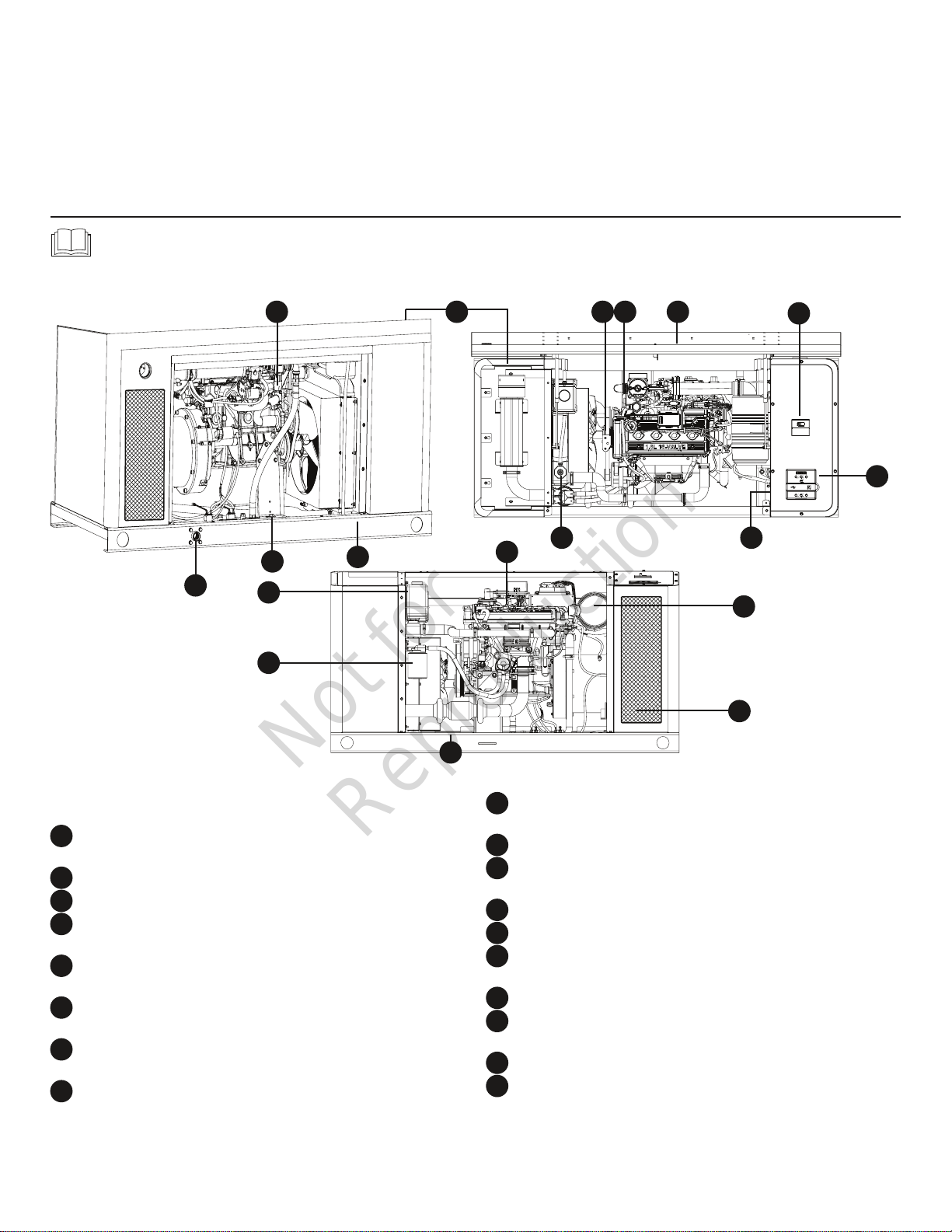
30 kW Generator
Read this operator’s manual and Important Safety Instructions before operating your generator.
Compare the illustrations of this model with your generator to familiarize yourself with the locations of various controls
and adjustments. Save this manual for future reference.
Back Top
M
U
N
L
R
P
A
J
S
K
Front
B C D
E
F
H
G
T
Generator is pictured with access doors removed for clarity
and screen guard open for clarity.
Exhaust Port — High-performance muffler lowers engine
A
noise to comply with most codes.
Engine Label — Identifies engine model and type.
B
Oil Dip Stick — Used to check the engine oil level.
C
Roof Access Opening — Provides access to control panel,
D
oil filter, etc.
Circuit Breaker Enclosure — Equipped with removable top
E
to assist with conduit connection.
Control Panel — Used for various test, operation and
F
maintenance functions. See System Control Panel.
Air Cleaner — Protects engine by filtering dust and debris
G
out of intake air.
Fuel Selection Switch — Select natural gas or liquid
H
propane (LP vapor) supply.
10
Oil Fill Cap — Remove to service the engine with
J
recommended oil.
Coolant Fill — Provides access for filling engine coolant.
K
Coolant Recovery Bottle — Provides visual indicator of
L
engine coolant level.
Fuel Inlet — Fuel supply is connected here.
M
ID Label — Identifies unit by serial number.
N
Rear Access Panel Opening — Provides access to various
P
components of generator.
Oil Filter — Filters engine oil to prolong system life.
R
Front Access Panel Opening — Provides access to various
S
components of generator.
Battery Location — Battery located for convenient access.
T
Fuel Type Selector — Position selector for Natural Gas (NG)
U
or Liquid Propane (LP vapor) supply.
Page 11
Not for
Reproduction
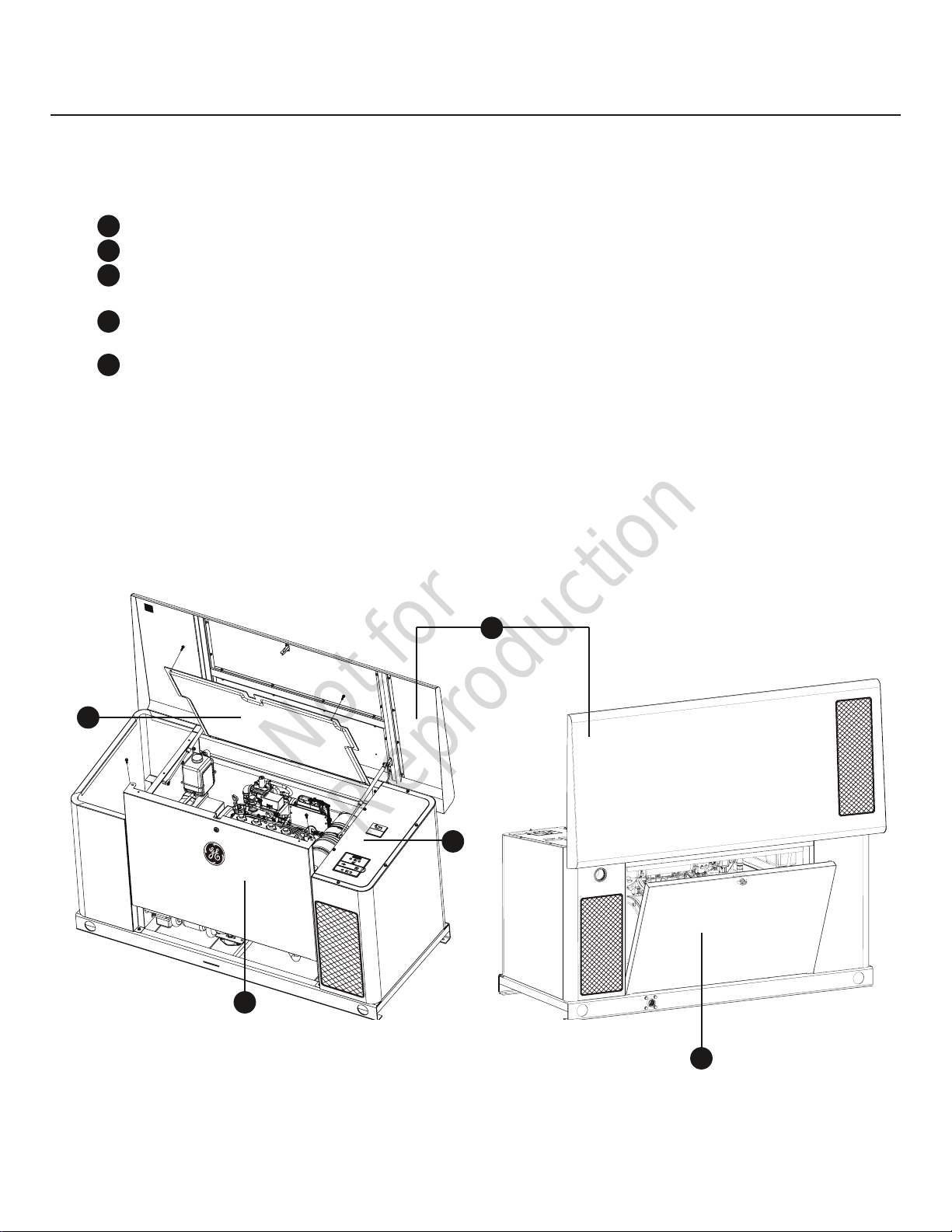
Access Ports
The generator is equipped with an enclosure that has several
access panels, as shown.
The access panels and the components located behind them
are listed below:
A -
B -
C -
D -
E -
Roof (Control Panel, internal guard)
A
Front Access Panel (oil drain and oil filter)
B
C
Internal Guard (air filter, oil dipstick, coolant
bottle)
Rear Access Panel (fuel regulator, fuel selector,
D
and engine starter)
E
Control Panel Cover (field wiring and control wires)
A
C
E
B
D
11
Page 12

Not for
Reproduction
Each generator is shipped with a set of identical keys. These
keys fit in the lock on the front and rear removable panels.
The roof must be unlocked in order for it to open.
To open roof:
1. Insert key into lock (A) of front panel. Gently push
down on roof above the lock to aid in turning the key.
Turn key one quarter turn clockwise.
A
2. Lift roof to the open position.
To open internal guard:
1. Ensure the roof is in the open position.
2. Remove the two bolts (B) that secure the internal
guard to the unit.
A
B
To remove front panel:
1. Remove the two bolts (C) that secure the panel to the
unit.
C
2. Lift panel to remove from unit.
To secure front panel:
1. Place panel in unit.
2. Secure the panel with two bolts.
To remove rear panel:
1. Insert key into lock (D) of rear panel. Turn key one
quarter turn counterclockwise to unlatch.
C
D
B
3. Lift up on panel and secure with tab on roof latch.
To secure internal guard:
1. Move holding tab on roof latch to release the panel,
then lower the panel into place.
2. Secure the panel with two bolts.
D
2. Open panel so that it clears the hinges.
3. Lift panel to remove from unit.
To secure rear panel:
1. Slide panel into place on unit.
2. Secure the panel with keyed lock (turn clockwise to
latch).
12
Page 13

Not for
Reproduction
System Control Panel
The generator control board, located inside the generator,
under the roof, is shown below. Brief descriptions of the
controls used during installation are:
‑ Menu/Programming Navigation Buttons — See Menu
A
section for details
‑ Mini USB Port — Authorized Dealer Service Use Only
B
- Generator Operation Control Buttons —
C
•“AUTO” Normal operating position. Press and hold
button to put unit into Automatic mode. If an utility
power outage is sensed, the system will start the
generator. When utility power is restored, AUTO lets
the engine stabilize internal temperatures, shuts o
the generator, and waits for the next utility outage.
•“OFF” Turns o running generator, prevents unit from
starting, and resets any detected faults.
OFF must be pressed and held for more than 5 seconds in
order to reset service codes.
•“MANUAL” Used to manually start the generator.
‑ “AUTO” LED — LED will light when unit is placed into
*
AUTO mode. LED will blink if exercise cycle is not set or
set to OFF.
– 15 Amp Fuse — Protects the generator DC control
D
circuits. If the fuse has ‘blown’ (melted open) or was
removed, the engine cannot crank or start. Replace
the fuse using only an identical ATO 15 Amp fuse. One
spare fuse is supplied with the unit.
‑ Cover — This protective cover must be opened to
E
access the fuse and the USB port.
‑ Digital Display — Displays generator mode, menu
F
options, service codes, and service engine indicators
More information may be found in Controls in the
operator’s manual.
F
menu
A
B
auto
C
ok
esc
E
D
off manual
*
13
Page 14

Not for
Reproduction
Menu
ok
ok
ok
ok
ok
ok
ok
ok
ok
ok
ok
ok
The following chart shows the icons for the buttons that control the system control panel.
ok
MENU
ESCAPE (EXIT)
RIGHT ARROW
LEFT ARROW
MANUAL MODE
OFF
AUTOMATIC MODE
ENTER THE MENU (VIEW SETTINGS)
PRESS TO CONFIRM SELECTION WHEN PROGRAMMING.
RETURN TO LAST MENU ITEM
TOGGLE THROUGH MENU OPTIONS
SETTING SYSTEM PARAMETERS
TOGGLE THROUGH MENU OPTIONS
SETTING SYSTEM PARAMETERS
USED TO MANUALLY START THE GENERATOR. PRESS AND HOLD BUTTON TO START
THE GENERATOR.
TURNS OFF RUNNING GENERATOR, PREVENTS UNIT FROM STARTING, AND RESETS
ANY DETECTED FAULTS.
NORMAL OPERATING POSITION. PRESS AND HOLD BUTTON TO PUT UNIT INTO AUTOMATIC MODE. IF A UTILITY POWER OUTAGE IS SENSED, THE SYSTEM WILL START
THE GENERATOR. WHEN UTILITY POWER IS RESTORED, AUTO LETS THE ENGINE
STABILIZE INTERNAL TEMPERATURES, SHUTS OFF THE GENERATOR, AND WAITS FOR
THE NEXT UTILITY POWER OUTAGE.
The following chart describes key sequences for accessing different programming modes;
PRESS AND HOLD [ARROW LEFT AND ARROW RIGHT] FOR THREE SECONDS
TO ENTER THE PROGRAM MODE.
PRESS AND HOLD [ARROW LEFT, ARROW RIGHT AND ESC] FOR THREE SECONDS TO ENTER THE ADVANCED SETTINGS MODE.
PRESS AND HOLD [MENU AND ESC] FOR THREE SECONDS TO ENTER THE
WIRELESS LINKING MODE.
14
ok
GENERAL
SET‑UP
ADVANCED
SETTINGS
WIRELESS
LINK MODE
Page 15

Not for
Reproduction
General Set Up Screen
ok
ok
For general set up, press and hold the left arrow and right arrow for 3 seconds. Follow the prompts as outlined below.
NOTE: Date and Time were set at the factory and stored in the control panel memory. The Exercise Cycle was also set at
the factory. The default exercise cycle occurs on Tuesdays, at 2:00 P.M. Central Standard Time. To update or change these
settings, follow the steps below.
SET DATE
or
SET TIME
or
YEAR
FLASHING
or or or
HOURS
FLASHING
or or or
or
MONTH
FLASHING
MINUTES
FLASHING
DAY##
FLASHING
AM/PM
FLASHING
If set to OFF, display will read:
EXERCISE CYCLE OFF
or
SET EXERCISE
CYCLE
EVENT LOG
DAY OF WEEK
FLASHING
or or or or
HOURS
FLASHING
MINUTES
FLASHING
Display will scroll last service code event, date, time,
and ambient temperature of when the event occurred.
IF DURING PROGRAMMING NO BUTTONS ARE PRESSED FOR 30 SECONDS,
THE CONTROL PANEL WILL AUTOMATICALLY EXIT THE PROGRAM MODE.
AM/PM
FLASHING
or
15
Page 16

Not for
Reproduction
Control Panel Prompts
Automatic Mode
In Automatic Mode, the display screen will display via
scrolling text:
• Generating set READY - if the unit is in standby and
utility power is present.
• Generating set ON - if the unit is running and utility
power is not present.
• SERVICE CODE - if a system fault has been detected.
AUTOMATIC MODE
GENERATOR READY OR SERVICE CODE DESCRIPTION
(When Generator NOT Running - Auto Mode)
GENERATOR ON
(When Generator Running - Auto Mode)
General System Parameters
To view general system parameters, press the MENU button.
The following will scroll across the digital display and then
move to the next item:
• Run time
• Date
• Time
• Exercise Cycle date and start time
The user can press the LEFT ARROW or RIGHT ARROW at any
time to move to the next item.
The user can press ESCAPE to go back to Generating set
READY.
If no user inputs are made for 10 seconds after all the items
have been displayed, the control board will reset to
Generating set READY.
ok
(MENU)
RUN TIME
or
DAT E
or
TIME
16
or
EXERCISE CYCLE
Page 17

Not for
Reproduction
Advanced Settings Screen
ok
ok
ok
ok
ok
ok
Advanced setting parameters are preset at the factory for a typical installation. To view Advanced Settings items and/or to
change items, follow the instructions listed below.
NOTICE Advanced settings are critical to the operation of the unit. Careful consideration should be taken when working in
the Advanced Settings menu. Exercise caution when selecting and verifying parameters for the generating set and region
where the generating set is being operated. Confirm all settings before operating the generating set for the first time.
For advanced menu items, press and hold the left arrow, right arrow, and escape key for 3 seconds. Follow the
prompts as outlined below.
NOTICE In the Advanced Setting menu, a three button access code (left arrow, right arrow, and escape key must
be pressed once to enter the menu and again to change any setting. After each confirmation of a setting, the selection will
display solid for 2 seconds before moving to the next program item.
kW
or
Hz
or
PHASE
or
kW
FLASHING
or
50/60 Hz
FLASHING
or
SINGLE
or
THREE
FLASHING
or
ok
ok
ok
VOLTS
or
SOFTWARE
VERSION DISPLAYED
VOLTS
FLASHING
or
ok
17
Page 18

Not for
Reproduction
Operation
Important Owner’s Considerations
Engine Oil
NOTICE Any attempt to crank or start the engine before it has
been properly serviced with the recommended oil will result in
equipment failure.
• Refer to Maintenance section for coolant and oil fill information.
• Damage to equipment resulting from failure to follow this
instruction will void engine and generator warranty.
The engine is shipped from the factory pre-run and filled
with synthetic oil (API SJ/CF 5W-30). This allows for system
operation in a wide range of temperature and climate
conditions. Before starting the engine, check oil level
and ensure that engine is serviced as described in the
Maintenance section.
Coolant System
This engine is shipped from the factory filled with a 50-50 mix
of automotive (Ethylene glycol) anti-freeze and water. This
will provide optimum year round protection against freezing,
boiling and corrosion. The coolant system incorporates
an optional water heater that operates when ambient
temperature is below 80ºF AND utility power is present at
the transfer switch. Before starting the engine, check coolant
level as described in the Maintenance section
Battery
WARNING Battery posts, terminals and related accessories
contain lead and lead compounds, chemicals known to the State
of California to cause cancer and reproductive harm. Wash
hands after handling.
The installer must supply a valve-regulated, rechargeable
12 volt DC starting battery. See Battery in Final Installation
Considerations in the installation manual.
With the battery installed, all wiring to transfer switch and
generator completed, utility power supplied to the automatic
transfer switch, and the unit in AUTO mode, the battery
receives a trickle charge while the engine is not running. The
trickle charge cannot be used to recharge a battery that is
completely discharged.
15 Amp Fuse
The generator’s 15 Amp fuse is critical to correct system
operation. Your installer will ensure the fuse is properly
installed upon completion of the installation.
Automatic Operation
The generator’s control board constantly monitors utility
voltage. Should utility voltage drop below a preset level, the
control board will signal the engine to crank and start.
When utility voltage is restored above a preset voltage level,
the engine is signaled to shut down.
The actual system operation is not adjustable and is
sequenced by sensors and timers on the control board,
as follows:
Utility Voltage Dropout Sensor
• This sensor monitors utility source voltage.
• If utility source voltage drops below about 70 percent
of the nominal supply voltage, the sensor energizes
a 3 second timer. The timer is used to ‘sense’
brown-outs.
• Once the timer has expired, the engine will crank
and start.
18
Utility Voltage Pickup Sensor
This sensor monitors utility voltage. When utility voltage is
restored above 80 percent of the nominal source voltage,
a time delay starts timing and the engine will go to engine
cool-down.
Engine Cool‑down Timer
When utility power is sensed and the load transfers back to
the utility source, the engine will go into a cool down period
as described below:
• If the generator has run for MORE than 5 minutes,
once the utility transfer occurs, the engine will
continue to run for about 1 minute before shutting
down.
• If the generator has run for LESS than 5 minutes, once
the utility transfer occurs, the engine will continue to
run until 5 minutes has elapsed before shutting down.
Page 19

Not for
Reproduction
Setting the Exercise Timer
The generator is equipped with an exercise timer. During the
exercise period, the unit runs for approximately 20 minutes
and then shuts down. Electrical load transfer DOES NOT
occur during the exercise cycle (unless an utility power
outage occurs).
The generator will only enter the exercise cycle if the unit
is in the AUTO mode and this exact procedure is followed.
To set the exercise timer:
NOTICE The generator is set with a deservice code exercise
cycle setting of Tuesday at 2:00 P.M, Central Time. To change
the cycle setting, proceed with the following steps:
1. Choose the day and time you want your generator to
exercise.
2. Press and hold the left arrow and right arrow
simultaneously for three seconds to enter the General
Set-Up program mode. See General Set-Up flow chart
in Menu Section.
3. Verify and/or set the time and date on the unit.
4. Go to the SET EXERCISE prompt and hit the “OK”
button.
NOTICE Items will flash until they are selected.
SELECT DAY: Use the left or right arrow to toggle
through the days of the week, Once the day is
selected, hit the “OK” button.
SELECT HOUR: Use the left or right arrow to toggle
through between 1 and 12. Choose the hour of day
you want the generator to exercise then hit the “OK”
button.
SELECT MINUTE: Use the left of right arrow to toggle
between :00 and :59. Choose the minute of the day
you want the generator to exercise then hit the “OK”
button.
SELECT AM/PM: Use the left of right arrow to toggle
between AM and PM. Once chosen, hit the “OK”
button.
NOTICE During the weekly exercise cycle, the generator
will run for 20 minutes, but it will not supply power to the
building. During the exercise cycle, the in-building monitor
will continue blinking the GENERATOR READY green LED.
If you want to change the day and time the unit exercises,
simply perform the procedure again.
To turn off the generator exercise cycle, go to the OFF
selection within the day of the week menu and press OK. The
display will then scroll: EXERCISE CYCLE OFF.
19
Page 20

Not for
Reproduction
Maintenance
Servicing the System
Before performing any generator maintenance, always
perform the following steps:
1. Set generator’s circuit breaker to its OFF position.
2. Press and hold the control board OFF button.
3. Remove 15 Amp fuse from control board.
Service Code Detection System
The generator may have to run for long periods of time
with no operator present. For that reason, the system is
equipped with sensors that automatically shut down the
generator in the event of potentially damaging conditions,
such as low oil pressure, high temperature, over speed, and
other conditions.
The generator’s control board shows service code
descriptions scrolling across the digital display. The service
code descriptions are listed below:
• Low Battery Voltage
• Low Oil Pressure
• Under Voltage
• Over Voltage
• Engine Does Not Start
• Low Frequency
• Engine Overspeed
• High Coolant Temperature
• Transfer Switch Service code
• No Wireless Communication
• Battery Charge Circuit
• Service Engine
4. Utility voltage is present at generator control board.
Disconnect power before servicing control board by
removing the fuses from the transfer switch.
5. After all servicing has been completed, replace fuses
in transfer switch, replace 15 Amp fuse in control
board, set circuit breaker ON and press and hold
control board AUTO button for 3 seconds.
Reset Service code Detection System
The operator must reset the service code detection system
each time it activates. To do so, press the control board OFF
button for 5 seconds. Once the display turns off, leave it off
for at least 30 seconds. Remedy the service code condition,
then return the generator to service by pressing and holding
the control board AUTO button and installing the 15 Amp
fuse (if removed).
Low Battery Voltage
This service code is indicated by Low Battery Voltage scrolling
across the digital display and a single flash on the wireless
monitor. This condition occurs if the battery voltage drops
below the preset value. Causes for this problem may be a
service code battery or battery charge circuit. See Battery
Charge Circuit,
Remove the 15 Amp fuse and disconnect the battery from
the generator. Test the battery voltage. If voltage meets
specifications, take the battery to a local battery store for
analysis. Or contact your local service center for assistance.
Reinstall the battery (replace if necessary - see Battery in
Final Installation Considerations in the installation manual).
Then reset the service code detection system, as described
earlier.
Low Oil Pressure
This service code is indicated by Low Oil Pressure scrolling
across the digital display and two flashes on the wireless
monitor. The unit is equipped with an oil pressure sensor that
is monitored by the engine ECU. Should oil pressure drop
below the 50 psi range, the engine will shut down.
To remedy the low oil pressure condition, add the
recommended oil to the FULL mark on the dipstick.
If the low oil pressure condition still exists, the engine will
start, then shut down again. The service code will appear. In
this case, contact an authorized dealer.
20
Page 21

Not for
Reproduction
Under Voltage
This service code is indicated by Under Voltage scrolling
across the digital display and three flashes on the wireless
monitor. This condition is caused by a restriction in the
fuel flow, the electronic governing system not functioning
properly, a broken or disconnected signal lead, a failed
alternator winding, the control board circuit breaker is open,
or the generator is overloaded.
To remedy the problem, contact your installer or an
authorized dealer.
Over Voltage
This service code is indicated by Over Voltage scrolling across
the digital display and three flashes on the wireless monitor.
This feature protects devices connected to the transfer
switch by shutting the generator down if the generator
output voltage happens to increase above the preset limit.
This condition is most likely caused by a failed voltage
regulator, alternator excitation circuit or a load imbalance. To
remedy the problem, contact your installer or an
authorized dealer.
Engine Does Not Start
This service code is indicated by Engine Does Not Start
scrolling across the digital display and four flashes on the
wireless monitor. This feature prevents the generator from
damaging itself if it continually attempts to start in spite
of another problem, such as no fuel supply. Each time the
system is directed to start, the unit will crank for 10 seconds,
pause for 10 seconds, and repeat. If the system does not
begin producing electricity after approximately 2 minutes,
the unit will stop cranking.
The most likely cause of this problem is no fuel supply or
incorrect fuel selector setting. See Fuel Selection Switch in
the installation manual. Check the internal and external fuel
shut off valves to ensure they are fully open. Other causes
could be failed spark plug(s), a loose electronic governor
connection, a failed engine ignition, or the engine air filter
is clogged. You may need to contact your installer for
assistance if you can’t remedy these problems.
Low Frequency
This service code is indicated by Low Frequency scrolling
across the digital display and five flashes on the wireless
monitor. This feature protects devices connected to the
transfer switch by shutting the generator down if the engine
runs slower than 55 Hz for three seconds. This condition is
caused by a failed engine component, electronic governor
system, or by excessive loads on the generator. To resolve
the problem, contact your installer or an authorized dealer.
Engine Overspeed
This service code is indicated by Engine Overspeed scrolling
across the digital display and six flashes on the wireless
monitor. This condition can be caused by a problem within
the electronic governor system.
To resolve the problem, contact your installer or an
authorized dealer.
High Coolant Temperature
This service code is indicated by High Coolant Temperature
scrolling across the digital display and seven flashes on the
wireless monitor. The contacts of the temperature switch
are normally open. If the engine temperature exceeds a
predetermined temperature, the service code is detected
and the engine shuts down.
Common causes for this condition include running the
unit with an access doors removed, obstructed air inlet
or exhaust port, or debris in the engine compartment or
running unit with roof open.
To resolve the problem, let the engine cool down and remove
any accumulated debris and obstructions. Ensure that the
access doors are installed and the roof is closed whenever
the unit is running. If problem persists, contact your installer
or an authorized dealer.
Transfer Switch Service code
This service code is indicated by Transfer Switch Service
code scrolling across the digital display (if transfer switch is
equipped with service code detection) and eight flashes on
the wireless monitor.
The most likely cause of this service code is a blown fuse in
the transfer switch. To remedy the problem, contact your
installer or an authorized dealer.
No Wireless Communication
This service code is indicated by No Monitor Communication
scrolling across the digital display. The SERVICE NEEDED red
LED on the wireless monitor will flash 20 fast pulses, pause
5 seconds, and repeat if there is a loss in communication
between the wireless monitor and the generator.
To resolve the problem, move the wireless monitor closer to
generator. Re-link if necessary.
Battery Charge Circuit
This service code is indicated by Battery Charge Circuit
scrolling across the digital display. The most likely cause is
an electrical problem with the control panel. To remedy the
problem, contact your installer or an authorized dealer.
Service Engine
The engine is equipped with on-board diagnostics that
monitor the operation of emission related components. If
an emission related problem has been detected, the system
control panel will display Service Engine. If Service Engine
displays while the generator is running, a diagnostic trouble
code may be set or a problem may exist in the system which
has caused the engine emissions to go outside the standards
certified by the Environmental Protection Agency. It is the
responsibility of the operator to contact an authorized
service technician to repair this condition.
21
Page 22

Not for
Reproduction
Generator Maintenance
Generator maintenance consists of keeping the unit clean.
Operate the unit in an environment where it will not be
exposed to excessive dust, moisture or any corrosive vapors.
Cooling air louvers on the enclosure must not become
clogged with snow, leaves, or any other foreign material. To
prevent generator damage caused by overheating, keep the
enclosure cooling inlets and outlets clean and unobstructed
at all times.
Cleaning the Generator
1. Press and hold the control board OFF button.
2. Remove 15 Amp fuse from control board.
3. Clean generator as desired.
NOTICE Improper treatment of generator can damage it and
shorten its life.
• DO NOT expose generator to excessive moisture, dust, dirt, or
corrosive vapors.
• DO NOT insert any objects through cooling slots.
Check the cleanliness of the unit frequently and clean when
dust, dirt, oil, moisture or other foreign substances are visible
on its exterior/interior surface. Inspect the air inlet and outlet
openings inside and outside the enclosure to ensure air flow
is not blocked.
DO NOT use direct spray from a garden hose to clean
generator. Water can enter the engine and generator and
cause problems.
• Use a damp cloth to wipe exterior surfaces clean.
• Use a soft, bristle brush to loosen caked on dirt, etc.
• Use a vacuum cleaner to pick up loose dirt and debris.
• Use low pressure air (not to exceed 25 psi) to blow
away dirt. Inspect cooling air slots and openings on
the generator. These openings must be kept clean
and unobstructed.
4. Reinstall 15 Amp fuse in control board.
5. Press and hold the control board AUTO button.
Engine Maintenance
The maintenance of an engine and related components are
critical to its operating performance and lifespan. Industrial
engines operate in an environment that often include hot
and cold temperatures and extreme dust. The recommended
maintenance schedule is listed in this section, however,
environmental operating conditions and additional installed
equipment may require more frequent inspection and
servicing.
Engine Oil
The engine is shipped from the factory pre-run and
filled with synthetic oil (API SJ/CF 5W-30). This allows for
system operation in a wide range of temperature and
climate conditions.
Synthetic Oils
Synthetic oils have been available for use in industrial
engines for a relatively long period of time and may offer
advantages in cold and hot temperatures. However, it is not
known if synthetic oils provided operational or economic
benefits over conventional petroleum-based oils in industrial
engines.
The owner and/or authorized service technician should
review the operating conditions of the equipment to
determine the inspection and maintenance intervals. Proper
engine cooling and lubrication are very important, so pay
particular attention to these matters.
Use of synthetic oils does not permit the extension of oil
change intervals.
22
Page 23

Not for
Reproduction
Oil Recommendation
Select an engine oil viscosity that will best match the
prevailing daytime temperature.
RECOMMENDED SAE VISCOSITY GRADE ENGINE OILS
FOR THE BEST FUEL ECONOMY AND COLD STARTING, SELECT THE LOWEST SAE
VISCOSITY GRADE OIL FOR THE EXPECTED TEMPERATURE RANGE
HOT WEATHER
IF SAE 15W-30 GRADE
OIL IS NOT AVAILABLE,
SAE 30 GRADE MAY BE
USED AT TEMPERATURES
ABOVE 40°F (4°C).
SAE 30
SAE 5W-30
PREFERRED
COLD WEATHER
40°F (4°C)
Checking Engine Oil Level
The oil must meet GM specification 9986231. Motor oils
meeting this specification receive the API (American
Petroleum Institute) starburst symbol.
It is noted that the GF-4 oils are also “backwards compatible”
and are equal or better that previous grades of oil in all
aspects.
Note: Synthetic oil meeting ILSAC GF-2, API
certification mark and API service symbol
(shown at left) with “SJ/CF ENERGY CONSERVING”
or higher, is an acceptable oil at all temperatures.
Use of synthetic oil does not alter required oil
change intervals.
NOTICE It is important to be careful when checking engine oil
level. Oil must be maintained between “ADD” and the “FULL”
mark on the dipstick. To ensure that you are not getting a
false reading, make sure the following steps are taken before
checking the oil level.
1. Stop engine.
2. Set control board system switch to OFF.
3. Remove 15 Amp fuse from control panel.
4. Allow approximately five minutes for the oil to drain
back into the oil pan.
5. Remove the dipstick. Wipe with a clean cloth or paper
towel and reinstall. Push the dipstick all the way into
the dipstick tube.
6. Remove the dipstick and note the amount of oil on the
dipstick. The oil level must be between the “ADD” and
“FULL” marks.
7. If the oil level is below the “ADD” mark, reinstall the
dipstick and proceed to step 8.
8. Remove the oil filler cap from the valve cover.
9. Add the required amount of oil to bring the level up to,
but not over the “FULL” mark on the dipstick. Reinstall
the oil filler cap to valve rocker arm cover and wipe
any excess oil clean.
23
Page 24

Not for
Reproduction
Changing Engine Oil
CAUTION Avoid prolonged or repeated skin contact with used
motor oil.
• Used motor oil has been shown to cause skin cancer in certain
laboratory animals.
• Thoroughly wash exposed areas with soap and water.
KEEP OUT OF REACH OF CHILDREN. DON’T POLLUTE.
CONSERVE RESOURCES. RETURN USED OIL TO
COLLECTION CENTERS.
Change oil while the engine is still warm from running.
1. Press and hold the control board OFF button.
2. Remove 15 Amp fuse from control board.
3. Place oil drain hose into an approved container.
4. Remove brass fitting from end of drain hose and drain
oil into an approved container.
5. When oil has drained, replace brass fitting on hose.
6. Place an approved container under oil filter.
7. Remove oil filter and dispose of properly.
8. Before installing a new oil filter, lightly lubricate the oil
filter gasket with fresh, clean oil.
9. Install the oil filter by hand until the gasket contacts the
oil filter adapter, then tighten the oil filter 1/2 to 3/4 turn.
10. Add the required amount of oil to bring the level up to,
but not over the “FULL” mark on the dipstick. Reinstall
the oil filler cap to valve rocker arm cover and wipe any
excess oil clean.
11. Reinstall 15 Amp fuse in control board.
12. Press and hold the control board MANUAL button to
start engine. As engine warms up, check for oil leaks.
13. Stop engine by pressing and holding control board OFF
button.
14. Wait for oil to settle, check oil level and add if necessary.
15. Press and hold the control board AUTO button.
Engine Drive Belts
The engine installed in this equipment uses drive belt(s) that
drive the water pump and alternator. The drive belt(s) are an
integral part of the cooling and charging system and should be
inspected according to the maintenance schedule.
When inspecting the belts, check for:
• Cracks
• Chunking of the belt
• Splits
• Material hanging loose from the belt
• Glazing, hardening
If any of these conditions exist, the belt should be replaced.
24
Page 25

Not for
Reproduction
Engine Coolant System
It is important that the cooling system of the engine be
maintained properly to ensure proper performance and
longevity.
WARNING Hot pressurized coolant can cause severe injury.
• DO NOT open radiator cap when hot.
• Before servicing, allow coolant to cool.
NOTICE Alcohol or methanol based anti-freeze or plain water
are not recommended for use in the cooling system at any
time.
Coolant
With the engine cold, check the coolant level in the coolant
recovery bottle (see Controls). Specifications for the coolant
system can be found in the Maintenance chart of this
manual. Coolant Specification - ethylene-glycol 50-50
mixture with distilled water.
The cooling system must be maintained according to the
recommended maintenance schedule and inspection should
include:
• The regular removal of dust, dirt , debris from the
radiator core and fan shroud.
• Inspection of coolant hoses and components for leaks,
especially at the radiator hose connections. Tighten
hose clamps if necessary.
• Check radiator hoses for swelling, separation,
hardening, cracks, or any type of deterioration.
• Inspect the radiator cap to ensure proper sealing.
Engine Air Cleaner
Once each year service the air cleaner, as follows. If
operating in a dusty environment, service more often.
1. Press and hold the control board OFF button.
2. Remove 15 Amp fuse from control board.
3. Remove filter cartridge - Remove the service cover by
disengaging three clips and detaching cover, starting
with the bottom two clips and the top clip last. Gently
move the end of the filter back and forth, then rotate
while pulling straight out.
4. Clean outlet tube and check
Vacuator™ valve - Use a clean cloth
to wipe the filter sealing surface and
the outlet tube surfaces. Make sure
that all contaminant is removed
before the new filter is inserted. Be
careful not to damage the sealing
area on the tube.
Visually check and physically squeeze Vacuator valve
attached to service cover to make sure it is flexible
and not inverted, damaged or plugged.
5. Clean filter - Use a soft bristle brush to loosen dirt
and a vacuum cleaner to remove dirt and debris. Low
pressure air (not to exceed 25 psi) may also be used
to blow away dirt. Replace filter cartridge if any holes
are detected in filter media.
6. Install clean filter properly - Insert the filter carefully.
Seat the filter by hand, making certain it is completely
into the air cleaner housing before securing the cover
in place. To complete a tight seal, apply pressure
by hand at the outer rim of the filter, not the flexible
center. (Avoid pushing on the center of the urethane
end cap.) No cover pressure is required to hold
the seal.
NEVER use the service cover to push the filter into
place! Using the cover to push the filter in could cause
damage to the housing, cover, or fasteners and will
void the warranty. If the service cover hits the filter
before it is fully in place, remove the cover and push
the filter (by hand) further into the air cleaner and try
again. The cover should go on with no extra force.
7. Reinstall service cover - Once the filter is in place,
reinstall the service cover, positioning the cover with
the arrow and the word TOP to the top. Fasten the
top clip first, the bottom two clips last. Make sure that
all mounting bands, clamps, bolts, and connections
in the entire air cleaner system are tight and verify
absence of holes in piping - repair if needed.
8. Reinstall 15 Amp fuse in control board.
9. Press and hold the control board AUTO button.
25
Page 26

Not for
Reproduction
Generator Electrical System Maintenance
The generator’s electrical system incorporates computers
to control various related components. The electrical system
connections and ground circuits require good connections.
Follow the recommended maintenance schedule located in the
Maintenance section of this manual.
When inspecting the electrical system, check the following:
• Check positive (+) and negative (-) battery cables for
corrosion, rubbing, chafing, burning, and ensure tight
connections at both ends.
• Check battery for cracks or damage to the case.
Replace as necessary.
• Inspect engine wire harness for rubbing, chafing,
pinching, burning, and crack or breaks in the wiring.
Battery
• Verify that the engine harness connectors are
correctly locked in.
• Inspect ignition coil wire for hardening, cracking,
chafing, burning, separation, and split boot covers.
• Inspect spark plug wires for hardening, cracking,
chafing, burning, separation, and split boot covers.
• Inspect spark plugs at the required intervals per the
recommended maintenance schedule.
• Verify that all electrical components are securely
mounted to the engine or chassis.
• Verify that any additional electrical services installed
by the owner are properly installed in the system.
Servicing of batteries is to be performed or supervised
by personnel knowledgeable of batteries and the
required precautions. Keep unauthorized personnel away
from batteries.
Servicing the Battery
If it is necessary to service the battery, proceed as follows:
1. Press and hold the control board OFF button.
2. Remove 15 Amp fuse from control board.
3. Service or replace battery as required. See Battery
in Final Installation Considerations in the installation
manual for specific battery needed.
4. Connect red battery cable to battery positive terminal
(indicated by POSITIVE, POS, or (+)).
5. Connect black negative battery cable to negative
battery terminal (indicated by NEGATIVE, NEG, or (‑))..
WARNING Battery posts, terminals and related accessories
contain lead and lead compounds, chemicals known to the State
of California to cause cancer and reproductive harm. Wash
hands after handling.
6. Ensure hardware on both positive and negative
battery terminals is secure.
7. Reinstall 15 Amp fuse in control board.
8. Press and hold the control board AUTO button.
DON’T POLLUTE. CONSERVE RESOURCES, RETURN
USED BATTERY TO RECYCLING COLLECTION CENTER.
26
Page 27

Not for
Reproduction
Charging the Battery
If it is necessary to charge the battery, proceed as follows:
1. Press and hold the control board OFF button.
2. Remove 15 Amp fuse from control board.
3. Disconnect negative battery cable from negative
battery terminal (indicated by NEGATIVE, NEG, or (‑)).
NOTICE Failure to disconnect negative battery cable will result in
equipment failure.
• DO NOT attempt to jump start the generator.
• Damage to equipment resulting from failure to follow this
instruction will void engine and generator warranty.
4. Charge battery with battery charger at 2 Amps until
battery holds 12 Volts. DO NOT exceed 13.7 volts
when charging.
CAUTION With the system switch set to AUTO, the engine could
crank and start at any time without warning, resulting in
minor or moderate injury.
• To prevent possible injury that could be caused by such sudden
starts, always set the system switch to OFF if performing
maintenance on the system.
• Remove the 15 Amp fuse before working on or around the
generator or transfer switch.
5. Connect negative battery cable to negative battery
terminal (indicated by NEGATIVE, NEG, or (‑)).
6. Ensure hardware on both positive and negative
battery terminals is secure.
7. Reinstall 15 Amp fuse in control board.
8. Press and hold the control board AUTO button.
Fuel System Inspection and Maintenance
Natural Gas / Propane Fuel System
The fuel system installed on this industrial engine has been
designed to various standards to ensure performance and
reliability. To ensure compliance to these standards, follow the
recommended maintenance schedule contained in this section.
Pressure Regulator Maintenance and Inspection
NOTICE The pressure regulator components have been
specifically designed and calibrated to meet the fuel system
requirements of the engine.
If the regulator fails to operate or develops a leak, it should be
repaired or replaced with the OEM recommended replacement
parts.
When inspecting the regulator, check for the following items:
• Check for any fuel leaks at the inlet and outlet fittings.
• Check for any fuel leaks in the regulator body.
• Check to ensure the regulator is securely mounted
and the mounting bolts are tight.
• Check the regulator for external damage.
27
Page 28

Not for
Reproduction
Mixer / Throttle Control Device Maintenance and
Inspection
NOTICE The mixer and throttle body components have been
specifically designed and calibrated to meet the fuel system
requirements of the engine.
NOTICE A dirty air cleaner may significantly alter the mixer
performance.
When inspecting the mixer and throttle body, check for the
following items:
• Leaks at all fittings.
• Ensure the mixer and throttle body are securely
mounted.
Exhaust System Maintenance and Inspection
When inspecting the exhaust system, check for the following
items:
• Inspect exhaust manifold at the cylinder head for leaks
and that all retaining bolts and shields (if used) are in
place.
• Inspect manifold to exhaust pipe fasteners to ensure
they are tight and that there are not exhaust leaks.
Repair as necessary.
• Inspect air cleaner element according to the
recommended maintenance schedule found in this
section.
• Check fuel lines for cracking, splitting, or chaffing,
Replace if any of these conditions exist.
• Check for leaks at the throttle body and intake
manifold.
• Inspect oxygen sensor trical connector to ensure
connector is seated and locker, check wires to ensure
there is no cracking, splitting, chaffing, or burning.
Replace as necessary.
• Inspect exhaust pipe connection for leaks. Repair as
necessary.
Engine Exterior
Periodically inspect the engine exterior for contamination
and potential damage from dirt, leaves, rodents, spider webs,
insects, etc. and remove.
When Calling for Assistance
You must have the following information at hand if it is
necessary to contact a local service center regarding
service or repair of this unit:
Storage
The generator is designed for long term service as a backup
generator. There is no need to take any storage precautions.
However, if it becomes necessary to take the system out of
service for an extended period, call Technical Services at
888 575‑8226, between 8:00 AM and 5:00 PM CT for specific
recommendations.
1. Obtain the unit Model Number and Serial Number
from the unit ID label. See Controls for location of
the label or refer to the information recorded on the
inside front cover of the installation manual.
2. Obtain the engine identification numbers from the
engine label. See the Controls section for location of
this information.
28
Page 29

Not for
Reproduction
Maintenance Chart
This maintenance schedule represents the manufacturer’s recommended maintenance intervals to maintain proper engine/
equipment function. Federal, State, or Local regulations may require additional or more frequent inspection or maintenance
intervals than those specified above. Check with the authority having jurisdiction for details.
Perform the following maintenance on the engine at the hours indicated and at equivalent hour intervals thereafter.
Maintenance Interval Hours
After
each
1000 1500 2000 2500 3000 3500 4000 4500 5000
use
General Maintenance Section
Visual check for uid leaks X
Check engine oil level X
Check coolant level X
Change engine oil and oil lter
Check fuel system for leaks
Inspect accessory drive belts X X X X X
Inspect electrical system wiring X X
Inspect all vacuum lines and tting X X
Timing belt
Engine Coolant Section
Clean debris from radiator core
Change coolant - ethylene glycol 50-50 mixture w/ distilled water X X X X X
Inspect coolant hoses X X X
Replace coolant hoses and accessory drive belt
Engine Ignition System
Inspect battery case for leaks/damage X X X X X
Inspect battery cables X X X X X
Inspect all electrical connector retainer locks X X X X X
Replace spark plugs X X X
Inspect crank sensor timing wheel
Clean secondary ignition coil tower X X X X X
Check spark plug wires X
Replace spark plug wires X
Fuel System Maintenance
Inspect air cleaner
Check fuel shut-o valve function X X
Check fuel shut-o solenoid valve function X X
Check air induction system X X
Check intake manifold X X
Engine Exhaust System
Inspect exhaust manifold and piping X X
Check oxygen sensor connector X X
Before and after any service or maintenance activity
Every 2,000 Hours or two years, whichever occurs rst
Every 200 hours (or every 100 hours in severe
Every 100 hours or Annually
Contact customer service for details
Every 100 hours or 60 days of operation
Every 100 hours or Annually
environments) or Annually
29
Page 30

Not for
Reproduction
Troubleshooting
Problem Cause Correction
Engine is running, but no AC output
is available.
Engine runs good at no‑load but “bogs
down” when loads are connected.
Engine will not start; or starts and
runs rough.
1. Circuit breaker open or defective.
2. Fault in generator control panel.
3. Poor wiring connections or
defective transfer switch.
1. Short circuit in a connected load.
2. Generator is overloaded.
3. Shorted generator circuit.
4. Fuel pressure or mixture
is incorrect.
5. Kinked fuel line.
1. 15 Amp fuse missing or blown.
2. Fuel supply turned off or depleted.
3. Failed battery.
4. Fuel pressure is incorrect
1. Reset or replace circuit breaker.
2. Contact local service facility.
3. Check and repair.
1. Disconnect shorted
electrical load.
2. Turn off one or more loads.
3. Contact local service facility.
4. See Gaseous Fuel System in the
installation manual.
5. Remove kink. Replace
if necessary.
1. Install (new) 15 Amp fuse.
See System Control Panel.
2. Open fuel valve(s); check
propane tank.
3. Replace battery.
4. See Gaseous Fuel System in the
installation manual.
Engine shuts down during operation.
Loss of power on circuits.
30
1. Fuel supply turned off or depleted.
2. Fault code displayed on controller.
1. Generator circuit breaker is open.
2. Transfer switch problems.
1. Check fuel valves, fill
propane tank.
2. Count blinks and refer to
Fault Detection System.
1. Reset circuit breaker.
2. See transfer switch manual.
Page 31

Not for
Reproduction
U.S. EPA, and Briggs & Stratton Corporation Emissions Control Warranty Statement for Emergency Standby Engines
Your Warranty Rights And Obligations
February 2013
General Information
The U.S. EPA, and Briggs & Stratton (B&S) are pleased to explain the
emissions control system warranty on your Model Year 2013 - 2014
engine / equipment. In the U.S., new Emergency Standby Engines
must be designed, built, and equipped to meet stringent emission
standards. Engines less than 25 Hp must meet requirements of 40
CFR Part 1054. Engines greater than 25 Hp and less than 130 Hp
must meet requirements of 40 CFR Part 1048. B&S must warrant the
emissions control system on your engine / equipment.
See Denition of appropriate use of Emergency Standby below.
The emission-related warranty covers all components whose failure
would increase an engine’s non-evaporative emissions of any
regulated pollutant referenced below.
Manufacturer’s Warranty Coverage:
Briggs & Stratton warrants that the engine is free from defects in
material and workmanship, and is also designed, built, and equipped
to conform to applicable regulations under Section 213 of the Clean
Air Act, from the time the engine is sold, until the expiration of its
warranty period.
This warranty applies to all emission related engine components
whose failure would cause engine exhaust emissions to be out of
EPA compliance. Further, this warranty also applies to other engine
components damaged due to the failure of any of these emissions
related components.
If a warrantable emissions related component on your engine is
defective, the part will be repaired or replaced by B&S at no cost to
you including diagnosis, parts, and labor.
Warranty coverage period is ve years from date of original purchase,
and is oered to the original purchaser and each subsequent
purchaser so long as Owner’s Warranty Responsibilities are adhered
to.
Owner’s Warranty Responsibilities:
• Warranty claims shall be led according to the provisions of the
Briggs & Stratton Warranty Policy.
• An engine may not be warrantable if subjected to abuse, misuse,
neglect, improper maintenance, unapproved modications,
accidents not caused by Briggs & Stratton engines or equipment,
or by acts of God.
• Only those engines used as an Emergency Stationary Engine, as
dened below, are warrantable.
• You are responsible for presenting your engine / equipment to
a B&S distribution center, servicing dealer, or other equivalent
entity, as applicable, as soon as a problem exists. The warranty
repairs should be completed in a reasonable amount of time,
not to exceed 30 days. If you have any questions regarding your
warranty rights and responsibilities, you should contact B&S at
1-800-233-3723 or BRIGGSandSTRATTON.COM.
• If any components not scheduled for maintenance is repaired
or replaced under this warranty, the new part will be warranted
only for the remaining warranty period.
• If a warrantable component scheduled for maintenance fails
prior to its rst scheduled replacement, the part will be repaired
or replaced by B&S at no charge to the owner. Any such
component is only warrantable until the originally scheduled
maintenance period has expired.
• Add on or modied parts that are not exempted by the EPA may
not be used. The use of any non-exempted add on or modied
parts by the owner will be grounds for disallowing a warranty
claim. The manufacturer will not be liable to warrant failures or
warranted parts caused by the use of a non-exempted add on or
modied part.
MANUFACTURER OF RECORD
CHONGQING PANDA MACHINERY is the Manufacturer of Record for all Environmental Protection Agency (EPA) compliance issues related to the
use and performance of the engine.
Emergency Stationary Engine Denition
An Emergency Stationary Engine is dened as any stationary internal combustion engine whose operation is limited to emergency situations and
required testing and maintenance. Examples include stationary engines used to produce power for critical networks or equipment (including
power supplied to portions of a facility) when electric power from the local utility (or the normal power source, if the facility runs on its own power
production) is interrupted, or stationary engines used to pump water in the case of re or ood, etc. Stationary engines used for peak shaving
are not considered emergency stationary engines. Stationary engines used to supply power to an electric grid or that supply power as part of
a nancial arrangement with another entity are not considered to be emergency engines. Emergency stationary ICE may be operated for the
purpose of maintenance checks and readiness testing, provided that the tests are recommended by Federal, State or local government, the
manufacturer, the vendor, or the insurance company associated with the engine. Maintenance checks and readiness testing of such units is
limited to 100 hours per year. There is no time limit on the use of emergency stationary engines in emergency situations. The owner or operator
may petition the Administrator for approval of additional hours to be used for maintenance checks and readiness testing, but a petition is
not required if the owner or operator maintains records indicating that Federal, State, or local standards require maintenance and testing of
emergency ICE beyond 100 hours per year. Emergency stationary ICE may operate up to 50 hours per year in non-emergency situations, but
those 50 hours are counted towards the 100 hours per year provided for maintenance and testing. The 50 hours per year for non-emergency
situations cannot be used for peak shaving or to generate income for a facility to supply power to an electric grid or otherwise supply power
as part of a nancial arrangement with another entity. For owners and operators of emergency engines, any operation other than emergency
operation, maintenance and testing, and operation in non-emergency situations for 50 hours per year, as permitted above is prohibited.
Form NO. 80005429 Rev. A
31
Page 32

Not for
Reproduction
Limited Warranty
Coverage
Briggs & Stratton Power Products Group, LLC will repair or replace,
free of charge, any part(s) of the equipment that is defective in
material or workmanship or both. This warranty is effective for the
time periods and subject to the conditions stated below. For all
warranty service, find the nearest Authorized Service Dealer in our
dealer locator map at BRIGGSandSTRATTON.COM.
THERE IS NO OTHER EXPRESS WARRANTY. WARRANTY COVERAGE
FOR IMPLIED WARRANTIES, INCLUDING THOSE OF MERCHANTABILITY
AND FITNESS FOR A PARTICULAR PURPOSE, ARE LIMITED TO
THE WARRANTY PERIOD SET FORTH BELOW, OR TO THE EXTENT
PERMITTED BY LAW. LIABILITY FOR INCIDENTAL OR CONSEQUENTIAL
DAMAGES ARE EXCLUDED TO THE EXTENT PERMITTED BY LAW.
*
Warranty Period
PARTS 5 years †
LABOR 5 years †
TRAVEL 5 years † ‡
Some states or countries do not allow limitations on how long an
implied warranty lasts, and some states or countries do not allow the
exclusion or limitation of incidental or consequential damages, so the
above limitation and/or the above exclusion may not apply to you.
This warranty gives you specific legal rights and you may also have
other rights which vary from state to state or country to country.*
In Australia - Our goods come with guarantees that cannot be
*
excluded under the Australian Consumer Law. You are entitled to
a replacement or refund for a major failure and for compensation
for any other reasonably foreseeable loss or damage. You are also
entitled to have the goods repaired or replaced if the goods fail to
be of acceptable quality and the failure does not amount to a major
failure. For warranty service, find the nearest Authorized Service
Dealer in our dealer locator map at BRIGGSandSTRATTON.COM, or
by calling 1300 274 447, or by emailing or writing to salesenquires@
briggsandstratton.com.au, Briggs & Stratton Australia Pty Ltd, 1
Moorebank Avenue, NSW, Australia, 2170.
† Enclosure is warranted against surface rust and corrosion for the first year
of the warranty period. Surface rust and corrosion is defined as any rust
or corrosion that has penetrated the paint but has not penetrated through
the metal substructure.
Enclosure is warranted against rust-through for the first two years of the
warranty period. Rust-through is defined as rust or corrosion that has
penetrated completely through the paint and metal substructure.
† Accessory parts have a separate warranty. Refer to the warranty included
with the accessory part at purchase.
‡ Travel expenses are reimbursed as specified under the Briggs & Stratton
Warranty Guidelines document to authorized Briggs & Stratton dealers for
performing applicable warranty repair work.
is a trademark of General Electric Company
and is under license by Briggs & Stratton
Power Products Group, LLC.
32
The warranty period begins on the date of purchase by the first retail
or commercial customer. In order to ensure prompt and complete
warranty coverage, REGISTER YOUR PRODUCT IN ONE OF THREE
WAYS:
1. ONLINE AT BRIGGSANDSTRATTON.COM, OR
2. MAIL THE COMPLETED REGISTRATION CARD, OR
3. CALL 888‑575‑8226
SAVE YOUR PROOF OF PURCHASE RECEIPT. IF YOU DO NOT PROVIDE
PROOF OF THE INITIAL PURCHASE DATE AT THE TIME WARRANTY
SERVICE IS REQUESTED, THE MANUFACTURING DATE OF THE
PRODUCT WILL BE USED TO DETERMINE THE WARRANTY PERIOD.
Registration is not required to obtain warranty service.
Warranty terms continue on next page.
Copyright © 2013. All rights reserved. No part of this material may
be reproduced or transmitted in any form without the express
written permission of Briggs & Stratton Power Products Group, LLC.
Page 33

Not for
Reproduction
About Your Warranty
Only authorized service dealers may perform warranty repairs. Most
warranty repairs are handled routinely, but sometimes requests for
warranty service may not be appropriate. For example, warranty
service would not apply if equipment damage occurred because
of misuse, lack of routine maintenance, and shipping, handling,
warehousing or improper installation. Similarly, warranty coverage
will not be provided if the manufacturing date or serial number(s)
on the equipment has been removed or the equipment has been
altered or modified. During the warranty period, the authorized
service dealer, at its option, will repair or replace any part that, upon
examination, is found to be defective under normal use and service.
This warranty will not cover the following repairs due to:
1. Normal Wear and Maintenance: Outdoor Power Equipment
and engines, like all mechanical devices, need periodic parts
and service to perform well. This warranty does not cover
repair when normal use has exhausted the life of a part or
the equipment. Typical wear items include engine oil, oil
gauges, o-rings, filters, fuses, spark plugs, anti-freeze, starting
batteries, etc. Normal maintenance such as: adjustments,
loose or leaking clamps or connections, installation or startup operations, fuel system cleaning and obstruction due to
contamination.
2. Installation, Operation, Maintenance and Storage: This
warranty does not apply to equipment or parts that have
been subjected to improper or unauthorized installation
or alteration and modification, abuse, misuse, negligence,
accident, overloading, overspeeding, improper maintenance,
repair or storage so as to adversely affect its performance
and reliability.
3. Enclosure is not warranted for surface rust or corrosion
or complete rust-through that may result due to improper
installation, damage to painted surfaces that compromise
the paint’s corrosion prevention properties, or if the unit is
installed in environments that expose the generator to high
levels of corrosive agents.
This warranty will not cover equipment used in:
1. Equipment used for prime power. For purposes of this
warranty, Prime Power is defined as an application in which
the generator is a source of power where no electrical power
service is available from the UTILITY POWER GRID. If no
UTILITY power is available, the generator is considered the
prime power source.
2. Used, reconditioned, and demonstration equipment, or rental
equipment. Rental use means any use of this product in a
temporary or semi-permanently installed rental application.
Once equipment has experienced rental use, it shall thereafter
be considered rental equipment for purposes of this warranty.
3. Equipment used in life support applications.
4. Failures caused by any force majeure event or external force
beyond the manufacturer’s control or Act of God such as, but
not limited to freezing, theft, fire, collision, wars or riots, hail,
water or flood damage, tornados, hurricanes, or terrorist acts.
5. Use of non-original parts and non-authorized installation or
warranty service by unauthorized dealers.
6. Rodent and/or insect infestations.
This warranty also does not include:
1. Any and all expenses incurred investigating performance
complaints unless defective Briggs & Stratton materials and/
or workmanship were the direct cause of the problem.
2. The cost of rental equipment used while warranty repairs are
being performed (i.e., generators, pumps, etc.)
Warranty terms effective October 1, 2013.
80006513, Rev. A, 1 October 2013
33
Page 34

Not for
Reproduction
Product Specifications
30 kW
Rated Maximum Load Current (at 40°C/104°F, LP or NG):
125 Amps at 1.0pf
Rated AC Voltage 120/240 Volts
Phase Single phase
Rated Frequency 60 Hertz
Normal Operating Range -20°F (-28.8°C) to 104°F (40°C)
Output Sound Level per ISO 3744 69 dB(A) at 23 ft. (7 m)
at no load
70 dB(A) at 23 ft. (7 m)
at normal load
Shipping Weight 1,086 lb (493 kg)
This generator is rated in accordance with UL (Underwriters Laboratories) 2200 (stationary engine generator assemblies) and CSA (Canadian Standards Association)
standard C22.2 No. 100-4 (motors and generators).
34
Page 35

Not for
Reproduction
Notes
35
Page 36

Not for
Reproduction
Notes
is a trademark of General Electric Company
and is under license by Briggs & Stratton
Power Products Group, LLC.
Copyright © 2013. All rights reserved. No part of this material may
be reproduced or transmitted in any form without the express
written permission of Briggs & Stratton Power Products Group, LLC.
80005277 Rev. B
 Loading...