

Page 1

TINSEA517JBRZ 49-7594-1 10-08 JR
Air Conditioners
Safety Instructions . . . . . . . . . . .2
Operating Instructions
Controls—Dip Switches . . . . . . . . .3–5
Controls—Terminal
Connections . . . . . . . . . . . . . . . . . . .6, 7
On/Off Switch . . . . . . . . . . . . . . . . . . . .8
Ventilation Control . . . . . . . . . . . . . . . .8
Care and Cleaning
Air Filters . . . . . . . . . . . . . . . . . . . . . . . . .9
Base Pan . . . . . . . . . . . . . . . . . . . . . . . . .9
Exhaust Coils . . . . . . . . . . . . . . . . . . . . .9
Installation Instructions
Electrical Supply . . . . . . . . . . . . .11–13
Installing the Zoneline . . . . . . .14–21
Preparation . . . . . . . . . . . . . . . . . . . . .10
Servicing . . . . . . . . . . . . . . . . . . . . . . . .22
Troubleshooting Tips . . . . . . .23
Normal Operating Sounds . . . . . . .24
Consumer Support
Consumer Support . . . . . .Back Cover
Warranty . . . . . . . . . . . . . . . . . . . . . . .27
Cool Only, Heat/Cool and
Heat Pump Models
7500 Series
Owner’s Manual and
Installation Instructions
ge.com
Write the model and serial
numbers here:
Model # __________________
Serial # __________________
Find these numbers on a label
on the front case panel.
Zoneline
®
Vertical
Printed in China
Page 2
Consumer Support Troubleshooting Tips Care and Cleaning Operating Instructions Safety Instructions
IMPORTANT SAFETY INFORMATION.
READ ALL INSTRUCTIONS BEFORE USING.
WARNING!
For your safety, the information in this manual must be followed to minimize the risk of fire, electric
shock, or to prevent property damage, personal injury, or loss of life.
■ This Zoneline must be properly installed
in accordance with the Installation
Instructions before it is used.
See the Installation Instructions
in the back of this manual.
■ Replace immediately all electric service
cords that have become frayed or
otherwise damaged. A damaged power
supply cord must be replaced with
a new power supply cord obtained
from the manufacturer and not repaired.
Do not use a cord that shows cracks
or abrasion damage along its length
or at either the plug or connector end.
■ Product must be operated with
the electrical plug supplied with the
product. Do not replace the electrical
plug supplied with the product.
■ If the receptacle does not match the plug,
the receptacle must be changed out by
a qualified electrician.
■ Unplug or disconnect the Zoneline
at the fuse box or circuit breaker before
making any repairs.
NOTE: We strongly recommend that
any servicing be performed by a qualified
individual.
■ All air conditioners contain refrigerants,
which under federal law must be
removed prior to product disposal.
If you are getting rid of an old product
with refrigerants, check with the
company handling disposal about
what to do.
SAFETY PRECAUTIONS
READ AND FOLLOW THIS SAFETY INFORMATION CAREFULLY.
SAVE THESE INSTRUCTIONS
2
Page 3
Safety Instructions Operating Instructions Care and Cleaning Troubleshooting Tips Consumer Support
3
Controls–dip switches. ge.com
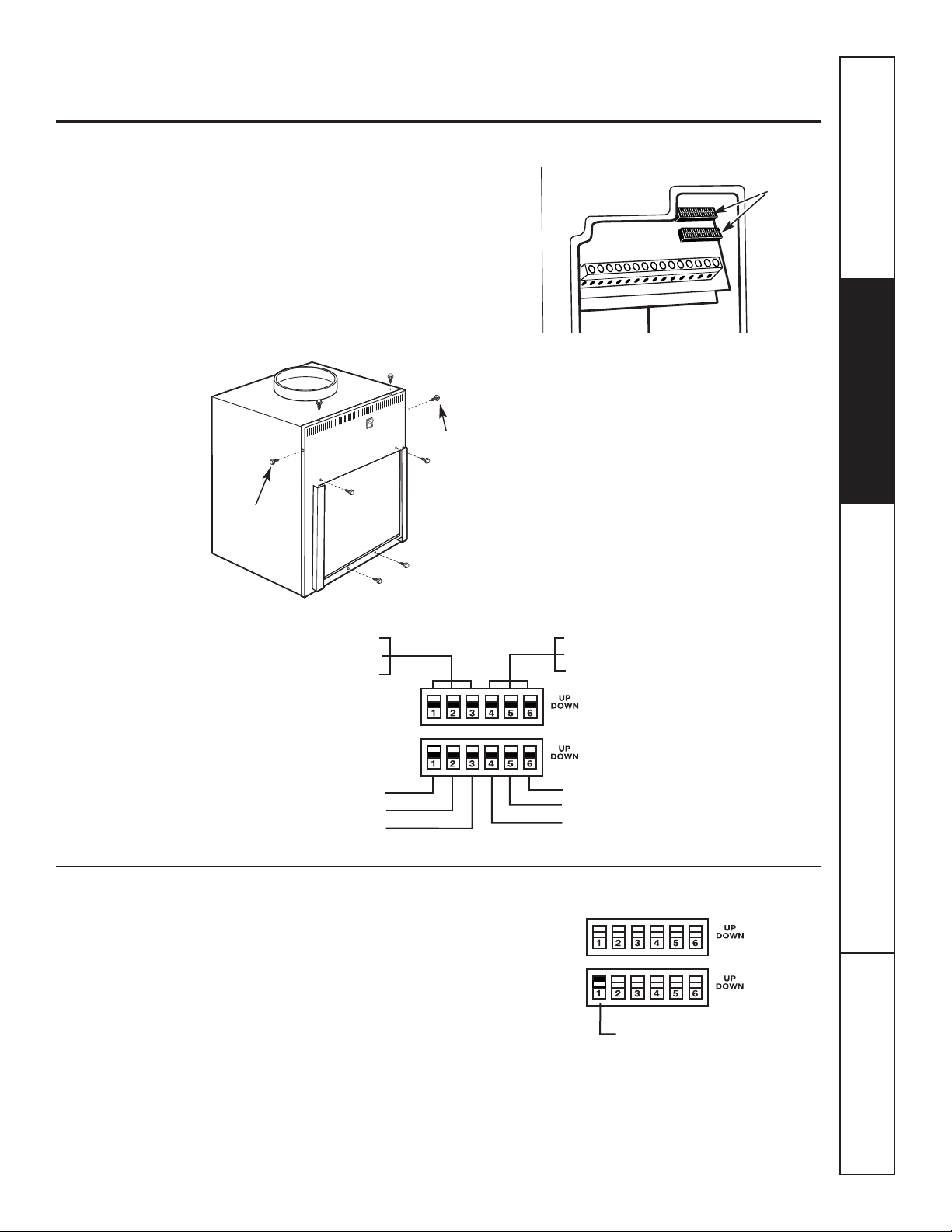
The dip switch controls are located behind
the front case panel, through an opening
on the front of the unit.
To access the dip switches, remove the front
case panel by removing the filter, taking out
the four front screws, the upper two screws from
the top of the panel and the shipping screws on
each side, if present. (Discard the two side shipping
screws, if present).
NOTE: The owner is responsible for setting
the appropriate dip switches and connecting
terminals.
Controls–Dip Switches
Dip
Switches
All Electric Heat (Heat pump models only)
When this switch is enabled (UP), heat pump
operation is locked out, causing the unit to provide
only electric resistance heat.
ALL I2R (All Electric Heat)
ALL I2R (All Electric Heat) (Heat-pump models only)
FREEZ S (Freeze Sentinel)
CONST FAN (Constant ON Fan)
TL1 (H) (Temp. Limit 1–Heat)
TL2 (H) (Temp. Limit 2–Heat)
TL3 (H) (Temp. Limit 3–Heat)
TL1 (C) (Temp. Limit 1–Cool)
TL2 (C) (Temp. Limit 2–Cool)
TL3 (C) (Temp. Limit 3–Cool)
No Function (Reserved for future use)
DUCT (Blower Fan)
OCCUPIED (Occupancy Sensor)
Side
shipping
screw
Side
shipping
screw
Page 4
Consumer Support Troubleshooting Tips Care and Cleaning Operating Instructions Safety Instructions
4
Controls–dip switches.
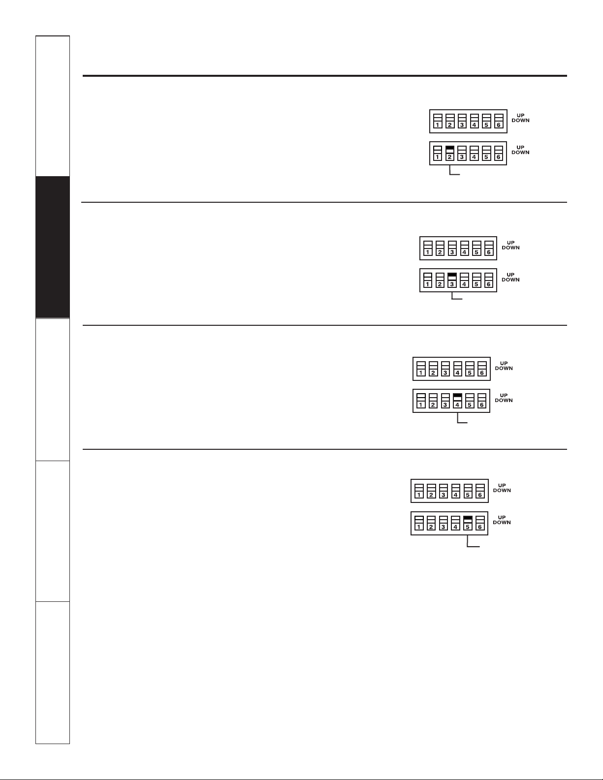
Freeze Sentinel (Requires room air sensor kit–RAVRMS)
When this switch is enabled (UP), it turns OFF
the freeze sentinel protection feature. With the
switch disabled (DOWN), the freeze sentinel is
activated which automatically provides heat
without user interface. This helps to prevent
plumbing damage by turning the heater
and fans ON at 41° F and OFF at 46° F.
Constant ON Fan
When this switch is enabled (UP), it allows the fan
to run continuously.
Occupancy Sensor
When this switch is enabled (UP), it allows the unit
to utilize an infrared motion sensor and a door
switch for occupancy detection. This feature
allows an energy management system
to be installed and operated in conjunction
with the unit.
FREEZE S (Freeze Sentinel)
CONST FAN (Constant
ON Fan)
OCCUPIED
(Occupancy Sensor)
Duct
The duct select function allows the indoor
fan to be operated at two variable fan speeds.
When this switch is enabled (UP), the unit
automatically selects either high or middle fan
speed (for longer ductwork applications). When set
in the down position, the unit is automatically
operated in either the middle or low fan speed
(for shorter ductwork applications).
DUCT
(Blower Fan)
Page 5
5
Safety Instructions Operating Instructions Care and Cleaning Troubleshooting Tips Consumer Support
ge.com
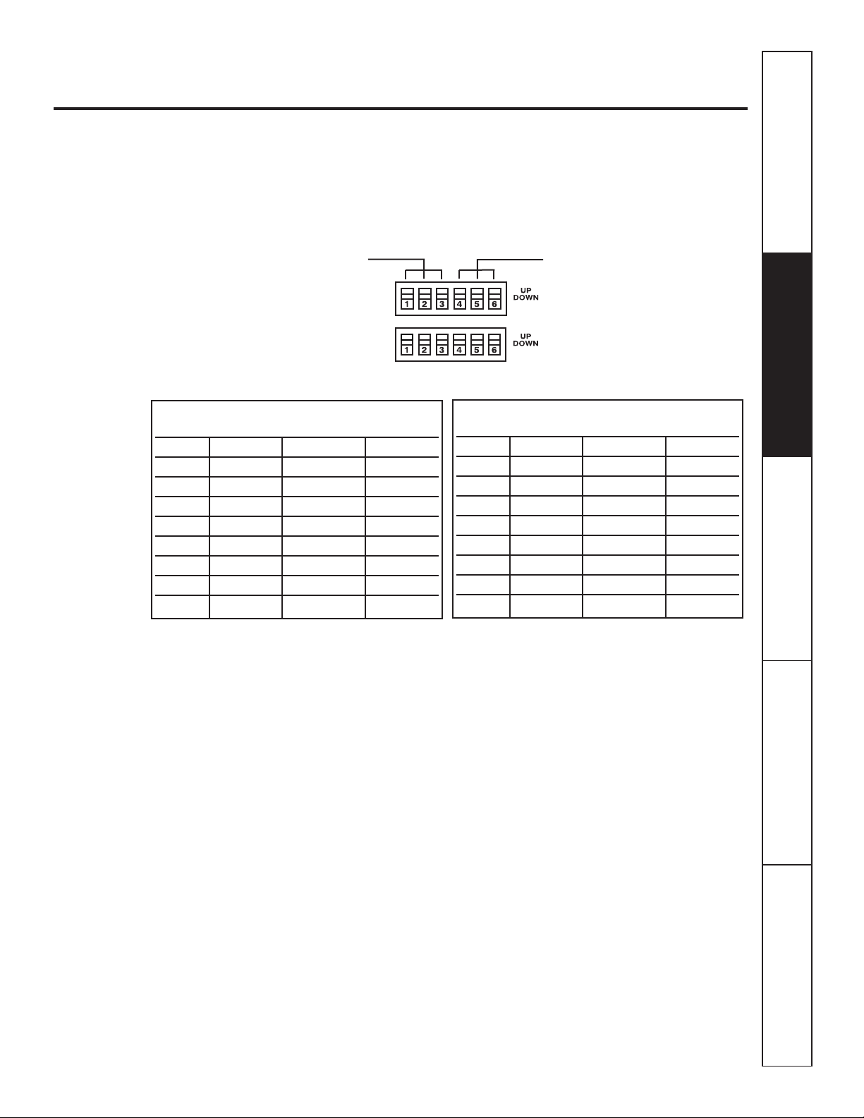
Temperature Limiting (Requires room air sensor kit–RAVRMS)
Temperature limiting can reduce energy costs
by limiting the lowest temperature that can be
set for cooling and the highest temperature that
can be set for heating. Temperature limiting is
controlled by switches 1–6 on the top block
of auxiliary controls. The first three switches are
used to select the cooling limits. The next three
switches are used to control the heating limits.
Temperature limiting during COOL mode
(all temperatures shown in °F)
UP DOWN Minimum Maximum
NONE 1, 2, 3 60° 85°
1 2, 3 64° 85°
1, 2 3 66° 85°
2 1, 3 68° 85°
2,3 1 70° 85°
1, 2, 3 NONE 72° 85°
1, 3 2 74° 85°
3 1, 2 76° 85°
Temperature limiting during HEAT mode
(all temperatures shown in °F)*
UP DOWN Minimum Maximum
NONE 4, 5, 6 60° 85°
4 5, 6 60° 80°
4, 5 6 60° 78°
5 4, 6 60° 76°
5,6 4 60° 74°
4, 5, 6 NONE 60° 72°
4, 6 5 60° 70°
6 4, 5 60° 65°
TL1 (C) (Temp. Limit 1–Cool)
TL2 (C) (Temp. Limit 2–Cool)
TL3 (C) (Temp. Limit 3–Cool)
TL1 (H) (Temp. Limit 1–Heat)*
TL2 (H) (Temp. Limit 2–Heat)*
TL3 (H) (Temp. Limit 3–Heat)*
* Not applicable to Cool-Only models
Page 6
6
Consumer Support Troubleshooting Tips Care and Cleaning Operating Instructions Safety Instructions
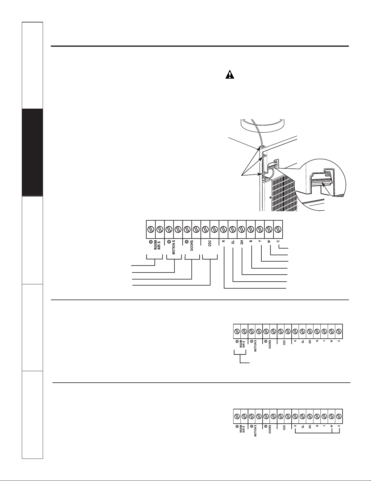
Controls—terminal connections.
Controls–Terminal Connections
The terminal connections are located behind
the front case panel through an opening
on the front of the unit.
To access the terminal connections, remove
the front panel by removing the filter, taking out
the four front screws, the upper two screws from
the top of the panel and the shipping screws on
each side, if present. (Discard the two side shipping
screws, if present.)
Insert the building hook-up wires into the bottom
of the terminals and tighten screws securely
to make the desired connections.
Route the wires from the terminal connections
through the unit wire guides and out through
the case wire guide.
NOTE: The owner is responsible for setting
the appropriate dip switches and connecting
terminals.
CAUTION:
Improper CDC wiring may damage the Zoneline
electronics or cause erratic Zoneline operation.
No common busing is permitted. A separate wire
pair must be run from each separate controlling
switch to each individual Zoneline.
Room Air Sensor (Requires room air sensor kit – RAVRMS)
When connected, the room air sensor will allow
utilization of the temperature limiting and freeze
sentinel features.
NOTE: If GE thermostat RAK148D1, RAK148P1
or RAK164D1, RAK164P1 is used with the unit,
the room sensor kit is not needed for temperature
limiting since this feature is incorporated in the
thermostats.
Route wires
through wire
guides
Room Air Sensor
Motion Sensor
Door Sensor
Central Desk Control
Common–Ground
White–Heater
Yellow–Compressor
Black–Reversing Valve
Green–High Speed Fan
Green–Low Speed Fan
Red–24V AC only
Room Air Sensor
Terminal
connections
Hydronic Heating (Requires Hydronic Heating Kit – RAVHW1, RAVHW2 or RAVHW3)
Required connections for hydronic heating kit.
NOTE: R, W, C terminal connections will
also be connected to the remote thermostat
if applicable.
Hydronic Heating
Page 7
Remote Thermostat
The unit will be controlled by a remote thermostat.
IMPORTANT:
The Zoneline thermostat connections
provide 24V AC only.
If using a digital/electronic wall thermostat,
you must set it to the 24V AC setting. See the
Installation Instructions for the wall thermostat.
CAUTION:
Damage to a wall thermostat or to the
Zoneline electronics can result from improper
connections. Exercise extra attention when
connecting blue and black wires. No line
voltage connections should be made to any circuit
in the thermostat. Isolate all wires in building from
line voltage.
7
Safety Instructions Operating Instructions Care and Cleaning Troubleshooting Tips Consumer Support
ge.com
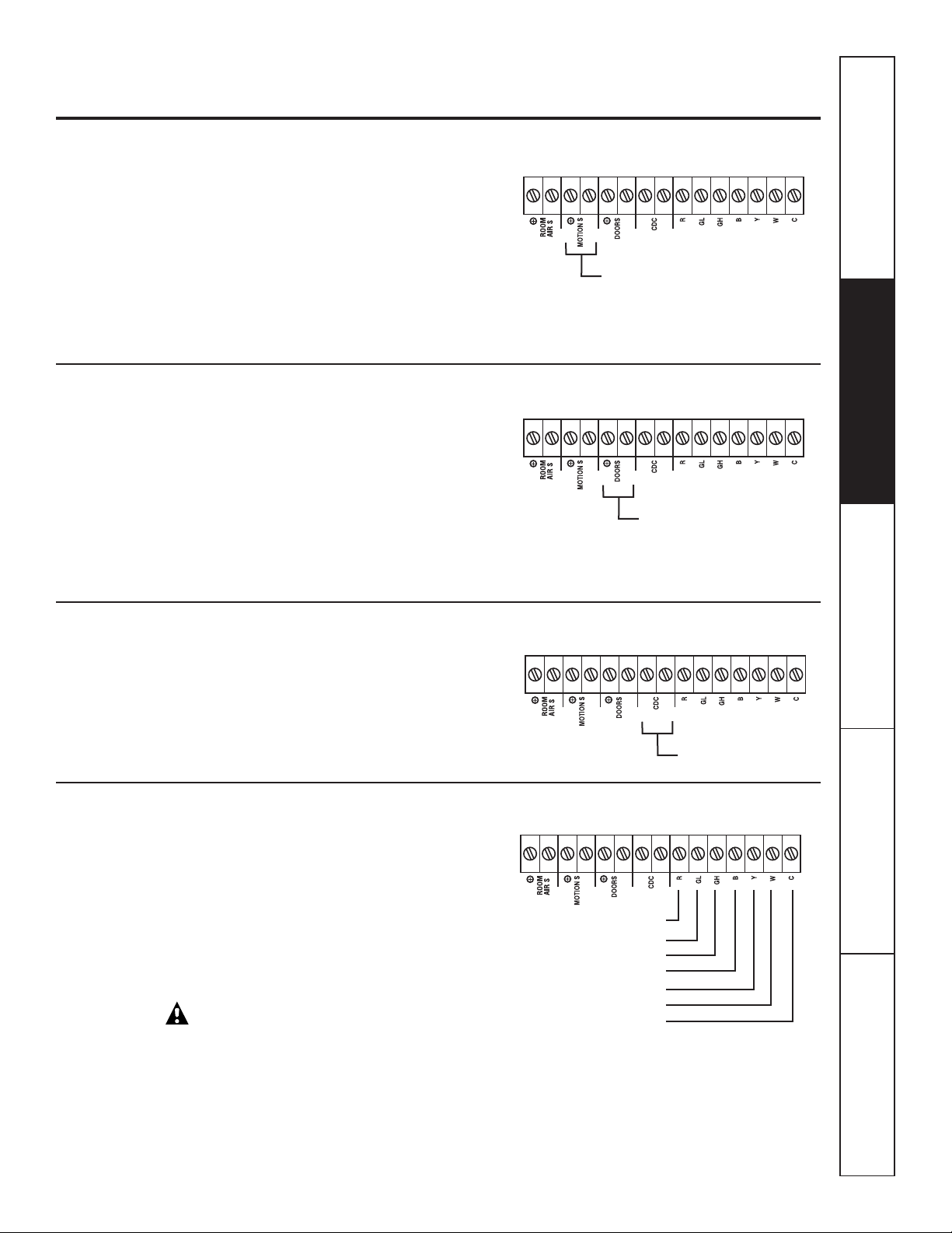
Door Sensor (Obtained locally)
The Occupancy Sensor dip switch must be
in the up position to use this feature.
When connected, the door sensor will detect
when the door in the room is opened or closed.
This feature must be used in conjunction with
the motion sensor.
The door and motion sensors work together
to automatically cycle the unit between normal
and energy management operations.
Central Desk Control
When connected, the unit lock-out is released
and it can be turned ON or OFF with a switch
located at the Central Desk Control. A separate
wire pair must be run from each separate
controlling switch to each individual Zoneline.
Motion Sensor (Obtained locally)
The Occupancy Sensor dip switch must be in
the up position to use this feature.
When connected, the wall mounted motion sensor
will detect motion in the room and automatically
cycle the unit between normal operation and
energy management operation.
The door and motion sensors work together
to automatically cycle the unit between normal
operation and energy management operation.
Motion Sensor
Door Sensor
Central Desk Control
Red–24V AC only
Green–Low Speed Fan
Green–High Speed Fan
Black–Reversing Valve
Yellow–Compressor
White–Heater
Common–Ground
Page 8
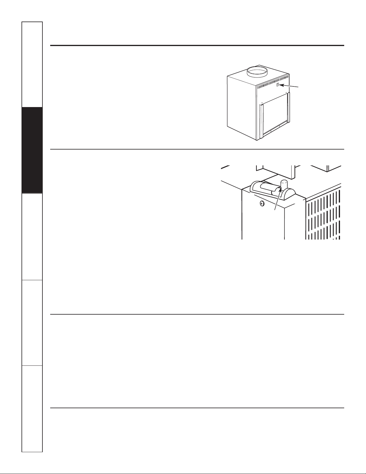
The ventilation control lever is located on the left
side of the Zoneline unit, behind the front case
panel.
To access the ventilation control lever, remove
the front panel by removing the filter, taking out
the four front screws, the upper two screws from
the top of the panel and the shipping screws on
each side, if present. (Discard the two side shipping
screws, if present).
When the lever is in the CLOSE position, only the air
inside the room is circulated and filtered.
When the lever is in the OPEN position, some
outdoor air will be drawn into the room. This
will reduce the heating or cooling efficiency.
To close the vent, push the vent lever handle
down, pull it forward and lock it up in place.
To open the vent, push the vent lever handle
down, push it back and lock it up in place.
Energy Tip: Keep the vent control in the CLOSE
position. The room air will be filtered and circulated.
8
Consumer Support Troubleshooting Tips Care and Cleaning
Operating Instructions Safety Instructions
Other features of your Zoneline.
About Heat Pumps (on some models)
Heat pumps can reduce operating costs by
exchanging heat from the outside air—even
when the outside temperature is below freezing—
and releasing that heat indoors.
To get the best economic benefit from your heat
pump, don’t change the room thermostat setting
very often. Raising the heat setting 2–3 degrees
will cause the Zoneline to use its electric heating
elements in order to reach the new temperature
setting quickly.
There is a three minute minimum compressor run
time at any setting to prevent short cycling.
The indoor fan motor starts before the compressor
and stops after the compressor cycles off.
The electric heating elements use much
more electricity than heat pumps and cost
more to operate.
Ventilation Control
Vent control
(push lever down
and pull forward
or back to
operate)
Open
Close
On/Off Switch
The unit on/off switch is located on the front
of the Zoneline.
To turn on the unit, press the top of the switch in.
To turn off the unit, press the bottom
of the switch in.
ON/OFF
switch
Do Not Operate Cool-Only Models in Freezing Outdoor Conditions
Cool-only air conditioners are not designed
for use when freezing outdoor conditions exist.
They must not be used in freezing outdoor
conditions.
Page 9
Indoor/Outdoor Coils
The exhaust coils on the Zoneline should be
checked regularly. If they are clogged with dirt
or soot, they may be professionally steam cleaned
by your GE service center. You will need to remove
the unit from the case to inspect the coils because
the dirt build-up occurs on the exhaust side.
9
Safety Instructions
Operating Instructions Care and Cleaning Troubleshooting Tips Consumer Support
Care and cleaning. ge.com
Base Pan
In some installations, dirt or other debris may
be blown into the unit from the outside and settle
in the base pan (the bottom of the unit).
In some areas of the United States, a “gel-like”
substance may be present in the base pan.
Check it periodically and clean, if necessary.
Turn off the Zoneline and disconnect the power supply before cleaning.
Outdoor coils
To maintain optimum performance, change the filter at least every 30 days.
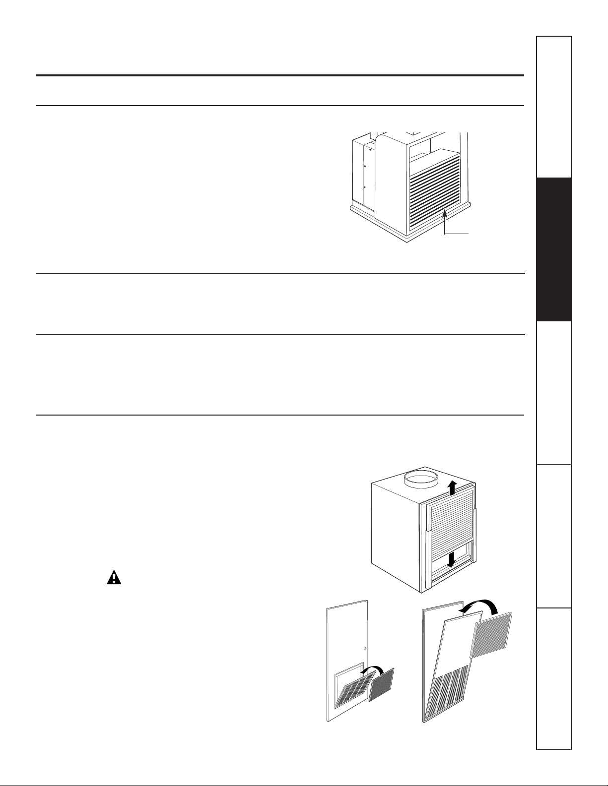
Air Filters
The most important thing you can do to maintain
the Zoneline is to change the filter at least every
30 days. Dirty filters reduce cooling, heating
and air flow.
Changing the filter will: Decrease cost of
operation, save energy, prevent clogged heat
exchanger coils and reduce the risk of premature
component failure.
CAUTION: Do not operate
the Zoneline without the filter in place. If a filter
becomes torn or damaged, it should be replaced
immediately.
Operating without the filter in place or with
a damaged filter will allow dirt and dust to reach
the indoor coil and reduce the cooling, heating,
airflow and efficiency of the unit.
Replacement filters should be purchased
from your local retailer where air conditioner
and furnace accessories are sold.
Filter size required is 20″ x 20″ x 1″.
Have the coils cleaned regularly.
Unit-mounted filter
Remove filter
Access-panel with
return air grille
Return air grille
Filter
Filter
To remove
and replace
the filter:
Drain
Clean the drain system regularly to prevent
clogging.
Page 10
BEFORE YOU BEGIN
Installation Zoneline Air
Instructions Conditioners
Read these instructions completely and carefully.
•
IMPORTANT
–
Save these instructions
for local inspector’s use.
•
IMPORTANT
–
Observe all governing
codes and ordinances.
• Note to Installer – Be sure to leave these
instructions with the owner.
• Note to Owner – Keep these instructions
for future reference.
• Proper installation is the responsibility of the installer.
• Product failure due to improper installation is not
covered under the Warranty.
• You MUST use all supplied parts and use proper
installation procedures as described in these
instructions when installing this air conditioner.
Questions? Visit our Website at: ge.com or call 800.GE.CARES (800.432.2737).
IMPORTANT ELECTRICAL
SAFETY–READ CAREFULLY
CAUTION:
• All electrical connections and wiring MUST
be installed by a qualified electrician.
• Follow the National Electrical Code (NEC)
and/or local codes and ordinances.
• For personal safety, this Zoneline unit and case
must be properly grounded.
• Protective devices (fuses or circuit breakers)
acceptable for Zoneline installations are specified
on the nameplate of each unit.
• Do not use an extension cord with this unit.
• Aluminum building wiring may present special
problems—consult a qualified electrician.
• When the unit is not running there is still voltage
to the electrical controls.
• Disconnect the power to the unit before
servicing by:
1. Removing the power cord (if it has one) from
the wall receptacle.
OR
2. Removing the branch circuit fuses or turning
the circuit breakers off at the panel.
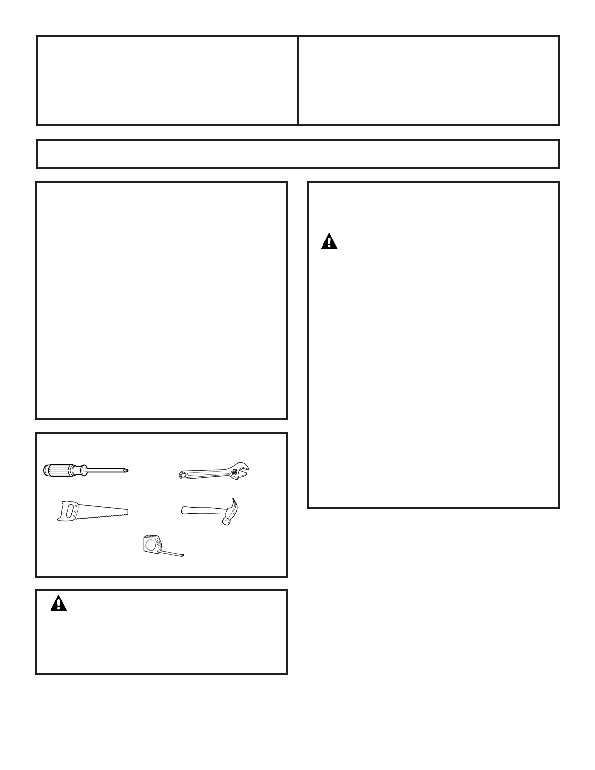
Phillips screwdriver
TOOLS YOU WILL NEED
10
WARNING:
Before beginning the
installation, switch power off at the service panel
and lock the area to prevent power from being
switched on accidentally. When the area cannot
be locked, securely fasten a prominent warning
device, such as a tag, to the service panel.
Adjustable wrench
Saw
Hammer
Tape measure
Page 11
11
Installation Instructions
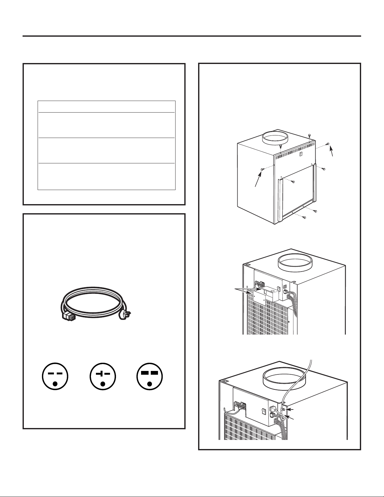
ELECTRICAL REQUIREMENTS
230/208 VOLT
ELECTRICAL SUPPLY
Tandem
15 Amp
230/208 volt receptacle configuration
Perpendicular
20 Amp
Large Tandem
30 Amp
• Use ONLY the wiring size recommended for single
outlet branch circuit.
• Proper current protection is the responsibility
of the owner.
A power supply kit must be used to supply power
to the Zoneline unit. The appropriate kit is determined
by the voltage, the means of electrical connection
and the amperage of the branch circuit. See the POWER
CONNECTION CHARTon page 13 to select the appropriate kit.
All wiring, including installation of the receptacle,
must be in accordance with the NEC and local codes,
ordinances and regulations.
Power supply kit
Recommended branch circuit wire sizes*
Nameplate
maximum circuit AWG Wire
breaker size size**
15A 14
20A 12
30A 10
AWG – American Wire Gauge
* Single circuit breaker from main box
** Based on copper wire, single insulated conductor at 60° C
NOTE: Use copper conductors only.
FOR 230/208 VOLT POWER CORD
CONNECTIONS ONLY
1. Remove the front panel by taking out the four
front screws, the upper two screws from the top
of the panel and the shipping screws on each side,
if present. (Discard the two side shipping screws,
if present.)
2. Remove the junction box cover and the junction box
and discard.
3. Connect the power cord, with a loop, through
the strain relief.
Strain relief
IMPORTANT:
Power cord must
have a loop.
Remove
junction box
and cover
Side
shipping
screw
Side
shipping
screw
Page 12
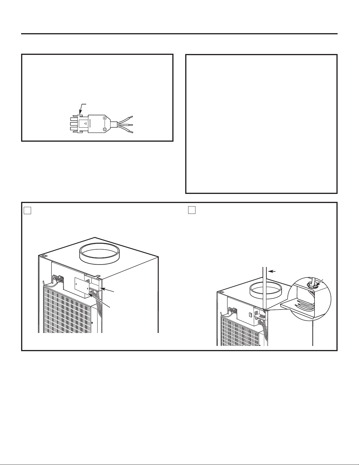
REMOVE JUNCTION BOX COVER
• Remove the junction box cover by taking out the front
two screws.
1
Junction box
Installation Instructions
12
DIRECT CONNECT APPLICATIONS
FOR 265 VOLT DIRECT CONNECT
APPLICATIONS ONLY
IMPORTANT: Connection of a 265V AC product
to a branch circuit MUST be done by direct connection
in accordance with the National Electrical Code. Plugging
this unit into a building mounted exposed receptacle
is not permitted by code.
These models must be installed using the appropriate
GE power supply kit for the branch circuit amperage
and the electrical resistance heater wattage desired.
See the POWER CONNECTION CHART on page 13
to select the appropriate kit.
It is the responsibility of the installer to ensure
the connection of components is done in accordance
with electrical codes.
Direct connection to branch circuit wiring inside
the provided junction box must be made by connecting
as follows in steps 1–3 below.
ATTACH CONDUIT
• Use the round knockout hole at the top
of the junction box to install conduit coming
from the branch circuit. Install and clamp the conduit
through the conduit clamp and bring wire leads into
the junction box. Leave 8″ of wire free from the end
of the conduit.
2
Conduit
FOR 230/208 VOLT DIRECT CONNECT
APPLICATIONS ONLY
Direct connection to branch circuit wiring inside
the provided junction box must be made by connecting
as follows in steps 1–3 below.
Connector
Conduit
clamp
Junction box cover
Page 13
13
Installation Instructions
DIRECT CONNECT APPLICATIONS
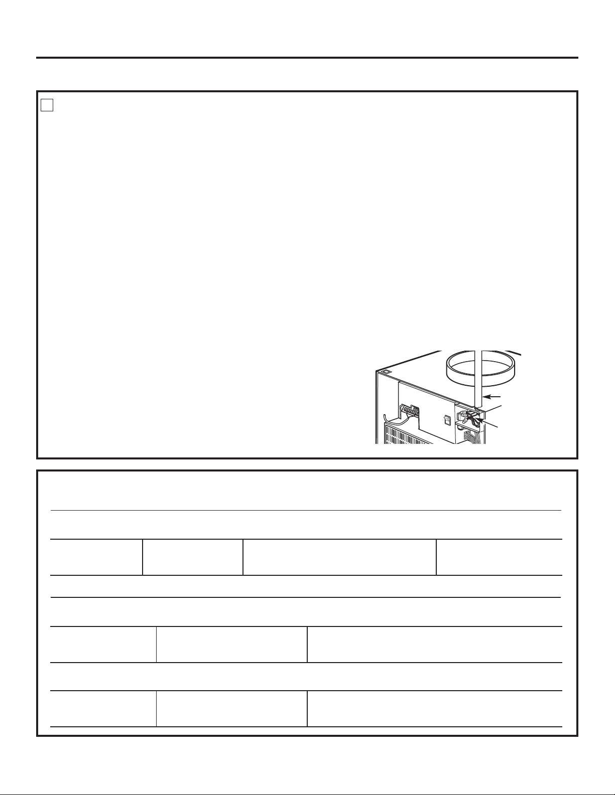
MAKE WIRE LEAD CONNECTIONS INSIDE THE JUNCTION BOX
1. Make all wire connections by using appropriate UL-listed electrical connectors and techniques.
2. Select the applicable wiring situation and follow the instructions accordingly:
3. Be sure that all wire leads are inside the junction box and not
pinched between the box and the unit. The green insulated
ground wire from the Zoneline MUST be connected to the branch
circuit ground wire.
4. Plug the 9-pin connector into the 9-pin receptacle in the junction box.
5. Replace the junction box cover by replacing the two screws
removed earlier.
3
230/208 Volt Wall Plug Heater Wattage
Power Supply Kits Configuration Circuit Protective Device @ 230/208 Volts
RAK3152 Tandem 15-Amp Time-Delay Fuse or Breaker 2.55/2.09 KW
RAK3202 Perpendicular 20-Amp Time-Delay Fuse or Breaker 3.45/2.82 KW
RAK3302 Large Tandem 30-Amp Time-Delay Fuse or Breaker 5.00/4.10 KW
230/208 Volt Heater Wattage
Power Supply Kits @ 230/208 Volts Circuit Protective Device
RAK4157 2.55 KW/2.09 KW 15-Amp Time-Delay Fuse or Breaker
RAK4207 3.45 KW/2.82 KW 20-Amp Time-Delay Fuse or Breaker
RAK4307 5.00 KW/4.10 KW 30-Amp Time-Delay Fuse or Breaker
265 Volt Heater Wattage
Power Supply Kits @ 265 Volts Circuit Protective Device
RAK5157 2.55 KW 15-Amp Time-Delay Fuse or Breaker
RAK5207 3.45 KW 20-Amp Time-Delay Fuse or Breaker
RAK5307 5.00 KW 30-Amp Time-Delay Fuse or Breaker
Conduit
Make wire lead
connections
• 1-Phase 220-240 VAC
When connecting the Zoneline to a single-phase circuit
for 230V applications:
Connect the white and black leads of the Zoneline
power supply kit to the branch circuit L1 and L2 leads.
(The white lead of the power supply kit should be
identified by the installer using electrical tape with some
color other than green or white.) Connect the green lead
of the power supply kit to the power supply and branch
circuit ground.
• 3-Phase 208 VAC
When connecting the Zoneline to a three-phase circuit
for 208V applications:
Connect the white and black leads of the Zoneline
power supply kit to the branch circuit L1 and L2 leads.
(The white lead of the power supply kit should be
identified by the installer using electrical tape with some
color other than green or white.) Connect the green lead
of the power supply kit to the power supply and branch
circuit ground.
• 3-Phase 208 VAC with “Crazy Leg”
When connecting the Zoneline to a three-phase circuit
with “Crazy Leg” for 208V applications:
Connect the white and black leads of the Zoneline
power supply kit to the branch circuit Neutral and L1
leads. (The white lead of the power supply kit should
be connected to neutral.) Connect the green lead of
the power supply kit to the power supply and branch
circuit ground.
• 3-Phase 253-277 VAC
When connecting the Zoneline to a three-phase circuit
for 265V applications:
Connect the white and black leads of the Zoneline
power supply kit to the branch circuit Neutral and L1
leads. (The white lead of the power supply kit should
be connected to neutral.) Connect the green lead of
the power supply kit to the power supply and branch
circuit ground.
Power Cord Connections
POWER CONNECTION CHART
Direct Connections
Page 14
Installation Instructions
14
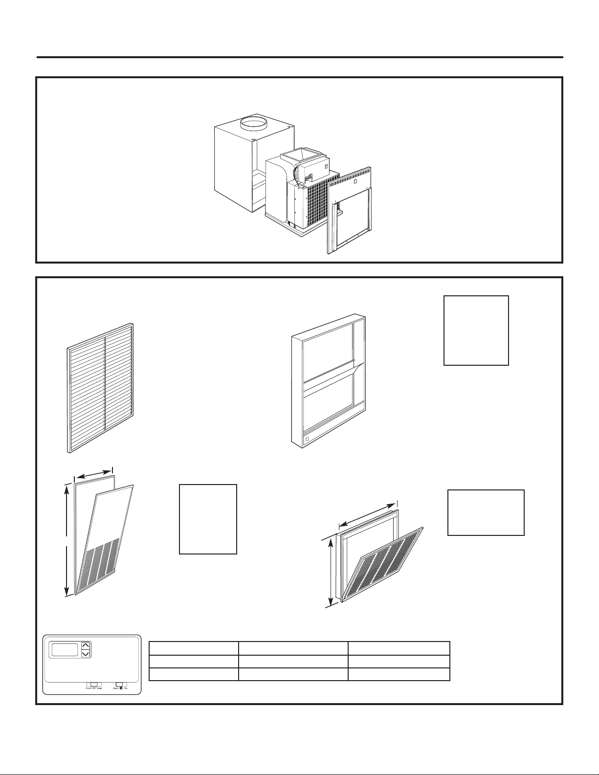
ZONELINE COMPONENTS
Case
Zoneline unit
Front Case Panel
REQUIRED ACCESSORIES
(Check the “Essential Elements” label on the unit.)
Architectural Louver
RAVAL1
Wall Plenum
RAVWP6 - 6″D x 19
3
⁄4″W x 32″H
RAVWP8 - 8″D x 19
3
⁄4″W x 32″H
RAVWP12 - 12″D x 19
3
⁄4″W x 32″H
RAVWP15 - 15″D x 19
3
⁄4″W x 32″H
Cutout
Dimensions:
20″ W x 32
1
⁄4″ H
Access Panel with
Return Air Grille
RAVRG1
Return Air Grille
RAVRG2
Cutout
Dimensions:
28″W x 48″H
Cutout
Dimensions:
20
3
⁄8″W x 203⁄8″H
OR
Wall Thermostat
Model Type Mechanical Thermostat Electronic Thermostat
Heat/Cool Models 4-wire 5-wire
Heat Pump Models 6-wire 6-wire
Check the thermostat instructions for correct wiring and installation requirements.
30″
50″
22 1⁄2″
22 1⁄2″
Page 15
Installation Instructions
15
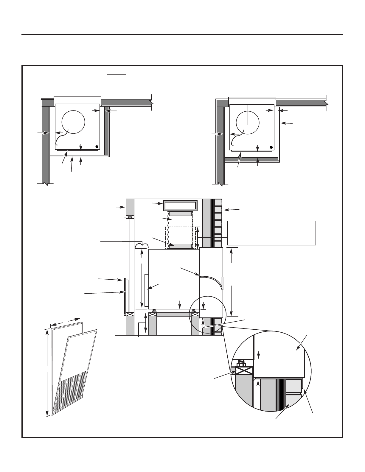
TYPICAL UTILITY CLOSET AND DIMENSIONS
(FOR REFERENCE ONLY)
Side View
Top View
Architectural Louver
10″
duct
Door/access panel
3″ min.
5″ min.
Unit front
3″
min.
14″ min. – Required only if optional Hydronic
Heating Kit (RAVHW1, RAVHW2, RAVHW3) is to
be installed. Clearance for installation should be
taken into consideration if this kit is to be used.
Exterior/Outside
Outside wall
Wall
plenum
Inside wall
Air discharge
outlet
Rigid
ductwork
Flexible or
rigid duct
Wall plenum
divider
31″
Option 1
Access panel with
return air grille
Option 2
Return air grille
Filter bracket
Secure platform
to the floor
Platform: 23
1
⁄4″ x231⁄4″ square
Min. load capacity: 175 lbs.
• 4″ min. from front of case – Unit
installed through FRONT of case.
• 5″ min. from front of case – Unit
installed through SIDE of case.
• 3″ min. from two sides of case.
Plenum
cutout
321⁄4″ H
x 20″ W
Drain fittings 3⁄4″
Outside wall
Platform
Wall plenum
Field supplied
outer flashing
10″
111⁄2″
A
B
A Minimum recommended access door width: 30″
B Minimum recommended access door height: 50″
UNIT INSTALLED THROUGH SIDE OF CASE
Top View
Architectural Louver
10″
duct
Door/access panel
3″ min.
4″ min.
Unit
front
3″
min.
10″
11
1
⁄2″
UNIT INSTALLED THROUGH FRONT OF CASE
Bottom of case approx. 2″
above bottom of plenum
8″ min.
for drain
access
Bottom of case approx. 2″
above bottom of plenum
Unit
Page 16
Installation Instructions
16
UTILITY CLOSET CONNECTION LOCATIONS
IMPORTANT: Plan and locate plenum, wall plug, drains and
thermostat carefully to avoid interference. Hard-to-reach locations
will make installation and service difficult!
Reference Dimensions
A Thermostat cable: 91⁄2′ long
B Power cord: 60″ long
C Case width and depth: 231⁄8″
D Case height: 31″
E Condensate drains: 3/4″ connector
• Primary Drain – Centerline of cutout is
approximately 51⁄4″ from left case wall
and 81⁄2″ from back case wall.
• Secondary Drain – Centerline of cutout is
approximately 61⁄2″ from left case wall
and 51⁄4″ from back case wall.
F Typical wall plug: 6″–12″ above case
G Room air sensor kit: 10′ long
Outside wall
Flex duct may be used
for transitions only
Use rigid duct for 90°
bends and tees
F
C
C
D
E
Platform
B
A
230/208 VAC
wall receptacle
or
conduit for direct
connection
G
Page 17
Installation Instructions
17
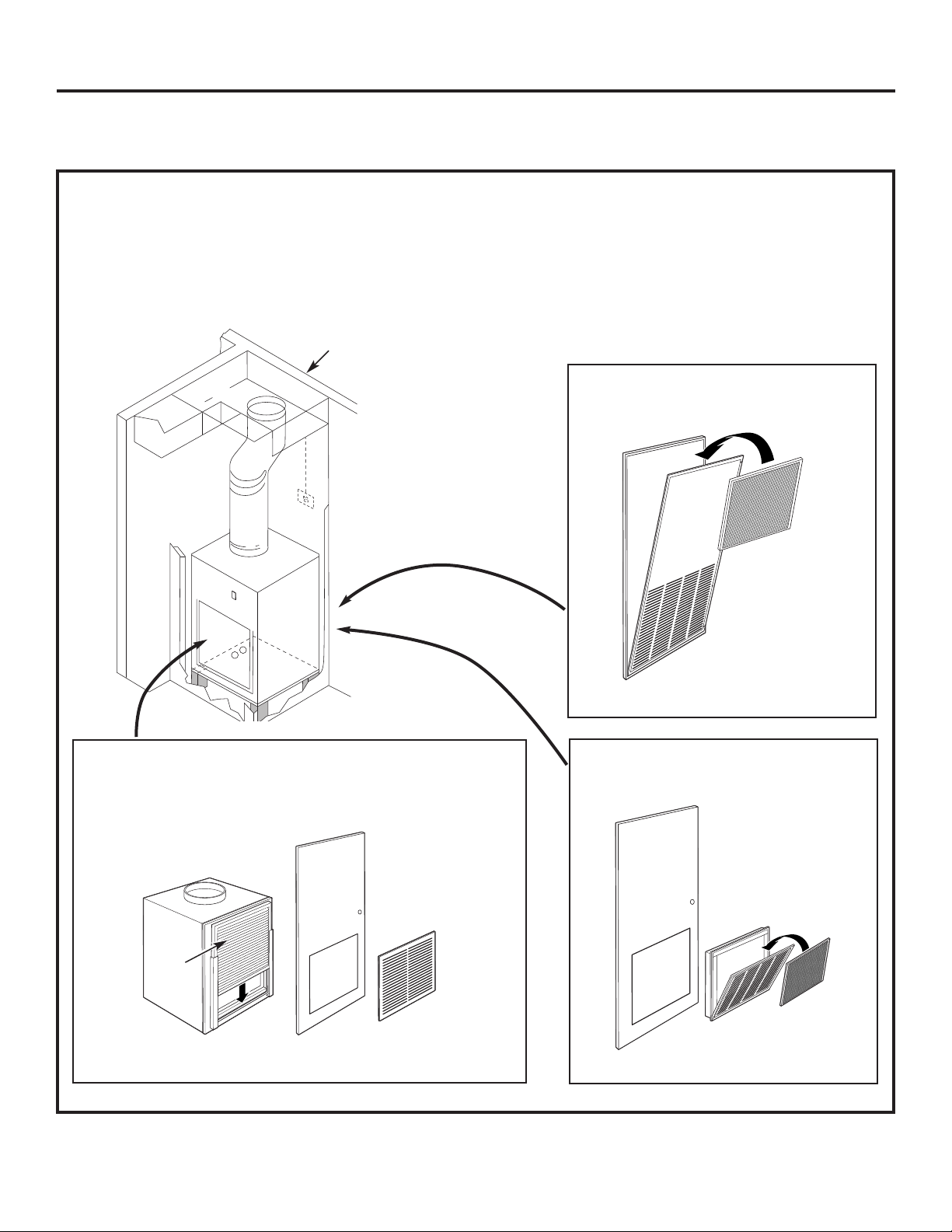
RETURN AIR GRILLE INSTALLATION OPTIONS
The room return air grille may be installed toward the front or either side of the unit. Improper return air arrangements
will cause performance problems.
There are three indoor return air grille installation options. Choose the option that best suits your installation
requirements. Follow the Installation Instructions provided with the return air grille accessory for installation details.
NOTE: Use only one filter in the installation. The filter may be installed on the unit or in the access panel/door.
Unit-mounted filter with a field-supplied return
air grille and access door/panel
RAVRG2 – Return air grille
RAVRG1 – Access panel with
return air grille
Filter
Filter
Filter
Outside wall
Option 1
Option 2
Option 3
Page 18

BUILD AND INSTALL THE ZONELINE
BASE PLATFORM
1. Construct a 231⁄4″ min. x 231⁄4″ min. square platform
with legs to raise the platform a minimum of 8″.
NOTE: The platform must have a load-bearing
capacity of 175 lbs. minimum.
1
Installation Instructions
18
WALL PLENUM AND ARCHITECTURAL LOUVER INSTALLATION
• Install the appropriate wall plenum through the exterior wall in accordance with the Installation Instructions
provided with the plenum.
IMPORTANT: The wall plenum is not designed to carry structural loads.
Proper wall header construction is required. The plenum requires proper flashing,
shim and caulk for a weather resistant installation.
Properly square
and level plenum.
Proper header for structural
support.
Apply proper caulking
and flashing.
Architectural Louver—
RAVAL1
Exterior/Outside Wall
Case
Wall Plenum
RAVWP6 – 6″D x 193⁄4″W x 32″H
RAVWP8 – 8″D x 19
3
⁄4″W x 32″H
RAVWP12 – 12″D x 19
3
⁄4″W x 32″H
RAVWP15 – 15″D x 19
3
⁄4″W x 32″H
2. Make drain hole cutout(s):
• Primary Drain – Centerline of drain is
approximately 51⁄4″ from left platform edge
and 81⁄2″ from back platform edge.
• Secondary Drain – Centerline of drain
is approximately 6
1
⁄2″ from left platform edge
and 51⁄4″ from back platform edge.
3. Place the platform in the utility closet
with the following clearance between it
and the interior surface of the walls/door/panel:
• 4″ min. from front of the case –
Unit to be installed through FRONT of case
• 5″ min. from front of the case –
Unit to be installed through SIDE of case
• 3″ min. from two sides of the case
4. Align the platform with the opening of
the wall plenum and secure to the floor
using appropriate brackets and bolts.
231⁄4″ min.
8″ min.
for drain
access
Cutout for drain
connection(s)
(see NOTE below)
Back of platform
Left side of platform
NOTE: Specific cutout size
for drain connections needs
to be determined by the installer
for the given installation situation.
51⁄4″
23
1
⁄4″ min.
5
1
⁄4″
61⁄2″
8
1
⁄2″
Page 19

INSTALL THE DRAIN(S)
An external or an internal drain must be attached
to the primary drain connector. A secondary drain
is supplied if required by state and local codes. Refer
to the local codes for proper installation of the drains.
If the secondary drain is not used, seal its drain port
with a 3/4″ MNPT plug.
External Drain
Attach a 90° PVC elbow to the unit’s female 3/4″ NPT
drain connector. Use the other end of the elbow to run
a 3/4″ Sch. 40 PVC pipe through the knockout holes of
both the wall plenum and the architectural louver to the
outside. Seal the gap between the plenum hole and PVC
tube. See the Installation Instructions in the RAVAL1.
Internal Drain
Attach PVC to the unit’s female 3/4″ NPT drain
connector. See the Installation Instructions
in the RAVAL1. Local codes may apply.
2
DUCTWORK
Prepare the closet ductwork for later connection
to the case.
The total flow rate (CFM) and external static pressure
(ESP) available can be estimated from the chart below.
Use these charts to select your fan speed setting. The
collar on top of the case accepts standard 10″ duct.
Pull all duct tight. Extra duct slack can greatly increase
static pressure.
CAUTION: Flex duct can collapse and
cause airflow restrictions. Do not use flex duct for 90°
bends or unsupported runs of 5 ft. or more.
3
Installation Instructions
Your airflow should be balanced based on many factors,
such as available ESP, room CFM, and ductwork. Consult
an HVAC engineer for proper applications. External static
pressure (ESP) can be measured with a manometer or
pitot tube. Once this ESP is established, you can
calculate the CFM using the above chart.
CFM Recommendations
9,000 BTU 12,000 BTU 18,000 BTU
275 300 325 350 375 400 450 500 550
•••
• = Recommended Mid Range
Higher CFMs tend to increase Sensible capacity,
enhance room circulation and increase duct noise,
while lower CFMs tend to increase Latent capacity
and reduce noise.
Side View
Inside wall
Female drain
fitting 3⁄4″
PVC
90° Elbow
PVC
(External drain)
PVC
(Internal drain)
Side View
Inside wall
Female drain
fitting 3⁄4″
Airflow – CFM@230 Volts and @ 265 Volts
Indoor Fan CFM
DUCT SELECT SWITCH
UP DOWN
ESP
(in. water)
High
CFM
Medium
CFM
Medium
CFM
Low
CFM
0.0
0.1
0.2
0.3
0.4
390
370
350
330
310
340
320
300
280
260
340
320
300
280
260
305
290
270
250
230
0.0
0.1
0.2
0.3
0.4
475
450
425
400
375
390
370
350
330
315
390
370
350
330
315
350
325
300
275
250
0.0
0.1
0.2
0.3
0.4
630
610
590
570
550
545
530
515
495
475
545
530
515
495
475
490
480
470
455
440
AZ75(H/E)09AZ75(H/E)12AZ75(H/E)18
To correct for 208 volts: 0.91
19
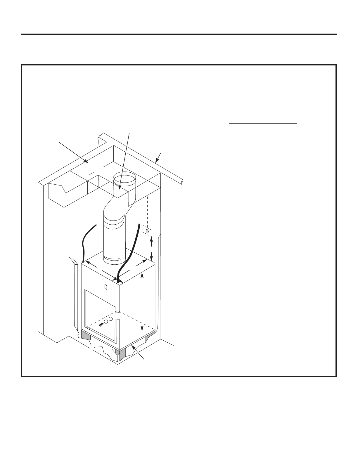
Page 20

INSTALL AND CONNECT THE CASE
1. Remove the front case panel and pull
the unit out of the case. Place the empty case onto
the platform in the closet with the outdoor side facing
the wall plenum opening. Align the case with plenum
opening and attach with six field-supplied sheet metal
screws (corrosion-resistant screws recommended).
2. Adjust all four leveling legs until the case is level.
3. Using field-supplied screws, bolt the case
to the platform.
4. Connect the internal or external drain(s) as necessary.
4
Installation Instructions
INSTALL AND GROUND
THE UNIT TO THE CASE
UNIT INSTALLED THROUGH FRONT OF CASE
1. Slide the back of the unit into the case. Push the unit
all of the way into the case until it stops.
NOTE: Either of the case sides may be removed
to enable the unit to be slid into the case.
2. Ground the unit to the case by installing the front
case-to-unit hex-bolt and/or case-to-unit side screw.
5a
Hex bolt
Air
discharge
outlet
Rigid
ductwork
Inside
wall
20
Primary female
drain fitting 3⁄4″
Leveling legs
INSTALL AND GROUND
THE UNIT TO THE CASE
UNIT INSTALLED THROUGH SIDE OF CASE
1. Slide the side of the unit into the case. Push the unit
all of the way into the case until it stops.
NOTE: Either of the case sides may be removed
to enable the unit to be slid into the case.
2. Attach the case side panel to the main case.
3. Ground the unit to the case by installing the front
unit-to-case hex-bolt and/or case-to-unit side screw.
5b
Side screw
Hex bolt
Side screw
(may be
installed on
either side)
External
drain
OR
Internal
drain(s)
Bolt case to
platform
Secondary 3⁄4″ drain
option. If not used,
seal with a MNPT plug
NOTE: Piping is not
supplied with the unit.
Obtain locally.
Page 21

Top duct
Clamp
Case top
duct adjusting
screws
MAKE UNIT ELECTRICAL
CONNECTIONS
1. Connect the thermostat wires to the unit and set
the dip switches to the appropriate settings.
NOTE: See the Controls–Terminal Connections
and Controls–Dip Switches sections
of this manual and the manual with
the separate thermostat for proper
connections and settings.
2. Make power connections to the unit.
NOTE: See the ELECTRICAL REQUIREMENTS and
DIRECT CONNECT APPLICATIONS sections,
as appropriate, of this manual for proper
connections.
3. Replace the case front panel by replacing the four
front screws and the two top screws.
6
Installation Instructions
Thermostat
Unit Connections
21
Maximum Wiring
Length for Thermostat
Connection to the Unit
66 ft. for AWG 18
60 ft. for AWG 20
40 ft. for AWG 24
AWG – American Wire Gauge
CONNECT THE TOP DUCT
1. Install the duct onto the air discharge outlet.
2. Secure the top duct to the unit by turning the four
case top duct adjusting screws until they are tight.
Use a field supplied clamp to lock the top duct
to the case.
7
Air
discharge
outlet
Rigid
ductwork
Inside
wall
Flexible or rigid
ductwork
Page 22

Installation Instructions
SERVICING
WARNING:
Before servicing, switch
power off at the service panel and lock the area to
prevent power from being switched on accidentally.
When the area cannot be locked, securely fasten
a prominent warning device, such as a tag,
to the service panel.
NOTE: We strongly recommend that any servicing
be performed by a qualified individual.
For ease of service, the unit can be removed
from the case:
1. Unplug the power cord and disconnect the wall
thermostat connections.
2. Raise the top duct by turning all four case top duct
adjusting screws counterclockwise.
3. Remove the front case panel.
4. Remove the front and/or side case-to-unit grounding
screw, if present.
5. Slide the unit out of the case.
22
FINAL CHECK
Review this Checklist before restoring power.
• Correct line voltage?
• Single circuit only?
• HVACR type breaker/fuse?
• Ductwork connected?
• Case and unit level?
• Wall plenum caulked? Level? Flashing?
• Drain connected?
• Wall thermostat wired correctly?
• Unit wired correctly?
• Hydronic plumbing connections (if applicable)
• Hydronic wiring connections (if applicable)
8
CONNECT POWER
1. If all the above items are correct, turn the power
on at the main service panel.
2. Turn the unit power switch, on the front of the unit,
to ON by pressing the top of the switch in.
9
Page 23

Safety Instructions Operating Instructions Care and Cleaning Troubleshooting Tips Consumer Support
Before You Call For Service… ge.com
Troubleshooting Tips
Problem Possible Causes What To Do
Zoneline does The unit is unplugged. • Make sure the Zoneline plug is pushed completely
not start into the outlet.
The fuse is blown/circuit • Check the house fuse/circuit breaker box and replace
breaker is tripped. the fuse or reset the breaker.
The unit is waiting for • This is normal. The Zoneline will start again after it resets.
the compressor overload
protector to reset.
Power failure. • There is a protective time delay (up to 3 minutes) to
prevent tripping of the compressor overload. For this
reason, the unit may not start normal heating or cooling
for 3 minutes after it is turned back on.
Zoneline does not cool Indoor airflow is restricted. • Make sure there are no curtains, blinds or furniture
or heat as it should blocking the air discharge grille or the return air grille.
Outdoor airflow is • Make sure the architectural louver is not restricted.
restricted or recirculated. This can cause the unit to cycle off due to the compressor
overload.
• Outdoor grille must have a minimum of 65% free area.
Non-GE grilles may be too restrictive for proper
performance. Consult your salesperson for assistance.
The air filter is dirty. • Change the filter at least every 30 days.
See the Care and Cleaning–Air Filters section.
The room may have • When the Zoneline is first turned on you need to
been hot or cold. allow time for the room to cool down or warm up.
Outdoor air is • Set the vent control to the CLOSE position.
entering the room.
Burning odor Dust is on the surface • This can cause a “burning” odor at the beginning of
at the start of the heating element. the heating operation. This odor should quickly fade.
of heating operation
The air is not always The heat pump is not • This is normal. The heat pump will produce warm air
cool or hot during producing hot air. but not as hot as air produced when the higher-cost
operation electric heat is used.
The fan switch may be • This causes the fan to blow room temperature air
set at continuous fan. even when the compressor or heater cycles off.
The continuous air movement provides better
overall temperature control.
The air does not feel The heat pump alone • Use the Electric Heat Option. This turns off the heat
warm enough during produces air that feels pump and warms with electric heat only.
heating operation cooler than desired. NOTE: Use of this option will result in increased energy
consumption.
23
Page 24

Consumer Support
Troubleshooting Tips
Care and Cleaning Operating Instructions Safety Instructions
24
Normal Operating Sounds
You may hear a pinging noise caused by water being
picked up and thrown against the condenser on rainy
days or when the humidity is high. This design feature
helps remove moisture and improve efficiency.
You may hear relays click when the controls cycle
on and off or are adjusted to change the room
temperature.
Water will collect in the base pan during high humidity
or on rainy days. The water may overflow and drip
from the outdoor side of the unit.
The indoor fan runs continuously when the unit is
operating in the cooling mode, unless the fan switch
behind the case front panel is set at fan cycle (up).
This will cause the fan to cycle on and off with
the compressor. You may also hear a fan noise
stop and start.
You may notice a few minutes delay in starting
if you try to restart the Zoneline too soon after
turning it off or if you adjust the thermostat right after
the compressor has shut off. This is due to a built-in
restart protector for the compressor that causes
a 3-minute delay.
During the defrost cycle, both indoor and outdoor
fans stop and the compressor will operate in the
cooling mode to remove frost from the outdoor coil.
After defrost, the unit will restart in electric heat to
quickly warm the room to the desired comfort level.
To protect the compressor and prevent short cycling,
the unit is designed to run for a minimum of 3 minutes
after the compressor starts at any thermostat setting.
Things that are normal.
3-Minute
Delay
“CLICK”
SILENCE
COMPRESSOR
PROTECTION
Page 25

Safety Instructions Operating Instructions Care and Cleaning Troubleshooting Tips Consumer Support
Notes. ge.com
25
Page 26

Notes.
Consumer Support Troubleshooting Tips Care and Cleaning Operating Instructions Safety Instructions
26
Page 27

For The Period Of: GE Will Replace:
One Year Any part of the Zoneline which fails due to a defect in materials or workmanship. During this
From the date of the limited one-year warranty, GE will also provide, free of charge, all labor and related service
original purchase to replace the defective part.
Five Years Any part of the sealed refrigerating system (the compressor, condenser, evaporator
From the date of the and all connecting tubing) which fails due to a defect in materials or workmanship.
original purchase During this four-year limited additional warranty, GE will also provide, free of charge,
all labor and related service to replace the defective part.
Five Years For the second through the fifth year from the date of original purchase, GE will replace
From the date of the certain parts that fail due to a defect in materials or workmanship. Parts covered are fan
original purchase motors, switches, thermostats, electric resistance heater, electric resistance heater protectors,
compressor overload, solenoids, circuit boards, auxiliary controls, thermistors, frost controls,
ICR pump, capacitors, varistors and indoor blower bearing. During this four-year limited
additional warranty, you will be responsible for any labor or on-site service costs.
Safety Instructions Operating Instructions Care and Cleaning Troubleshooting Tips Consumer Support
27
Vertical Zoneline Warranty.
■ Service trips to your site to teach you how to use
the product.
■ Improper installation, delivery or maintenance.
■ If you have an installation problem, or if the air
conditioner is of improper cooling or heating capacity
for the intended use, contact your dealer or installer.
You are responsible for providing adequate electrical
connecting facilities.
■ In commercial locations, labor necessary to move
the unit to a location where it is accessible for service
by an individual technician.
■ Failure or damage resulting from corrosion due
to installation in an environment containing corrosive
chemicals.
■ Replacement of fuses or resetting of circuit breakers.
■ Filters.
■ Failure of the product resulting from modifications
to the product or due to unreasonable use including
failure to provide reasonable and necessary
maintenance.
■ Failure or damage resulting from corrosion due
to installation in a coastal environment, except
for models treated with special factory-applied
anti-corrosion protection as designated
in the model number.
■ Damage to product caused by improper power supply
voltage, accident, fire, floods or acts of God.
■ Incidental or consequential damage caused
by possible defects with this air conditioner.
■ Damage caused after delivery.
■ Product not accessible to provide required service.
What GE Will Not Cover:
This warranty is extended to the original purchaser and any succeeding owner for products purchased
for use within the USA and Canada. If the product is located in an area where service by a GE Authorized
Servicer is not available, you may be responsible for a trip charge or you may be required to bring
the product to an Authorized GE Service location for service. In Alaska, the warranty excludes
the cost of shipping or service calls to your site.
Some states or provinces do not allow the exclusion or limitation of incidental or consequential damages.
This warranty gives you specific legal rights, and you may also have other rights which vary from state
to state or province to province. To know what your legal rights are, consult your local, state or provincial
consumer affairs office or your state’s Attorney General.
Warrantor: General Electric Company. Louisville, KY 40225
All warranty service provided by our Factory Service Centers,
or an authorized Customer Care
®
technician. To schedule
service, on-line, visit us at ge.com, or call 800.GE.CARES
(800.432.2737). For service in Canada, contact Gordon
Williams Corp. at 1.888.209.0999. Please have serial number
and model number available when calling for service.
Staple your receipt here.
Proof of the original purchase
date is needed to obtain service
under the warranty.
EXCLUSION OF IMPLIED WARRANTIES—Your sole and exclusive remedy is product repair as provided in this Limited Warranty.
Any implied warranties, including the implied warranties of merchantability or fitness for a particular purpose, are limited
to one year or the shortest period allowed by law.
Page 28

Consumer Support.
GE Appliances Website
ge.com
Have a question or need assistance with your appliance? Try the GE Appliances Website 24 hours a day,
any day of the year! For greater convenience and faster service, you can now download Owner’s Manuals,
order parts or even schedule service on-line.
Schedule Service ge.com
Expert GE repair service is only one step away from your door. Get on-line and schedule your service at
your convenience any day of the year! Or call 800.GE.CARES (800.432.2737) during normal business hours.
For service in Canada, contact Gordon Williams Corp. at 1.888.209.0999.
Real Life Design Studio ge.com
GE supports the Universal Design concept—products, services and environments that can be used by
people of all ages, sizes and capabilities. We recognize the need to design for a wide range of physical and
mental abilities and impairments. For details of GE’s Universal Design applications, including kitchen design ideas
for people with disabilities, check out our Website today. For the hearing impaired, please call 800.TDD.GEAC
(800.833.4322).
Parts and Accessories ge.com
Individuals qualified to service their own appliances can have parts or accessories sent directly to their homes
(VISA, MasterCard and Discover cards are accepted). Order on-line today, 24 hours every day or by phone
at 800.626.2002 during normal business hours.
Instructions contained in this manual cover procedures to be performed by any user. Other servicing
generally should be referred to qualified service personnel. Caution must be exercised, since improper
servicing may cause unsafe operation.
Contact Us ge.com
If you are not satisfied with the service you receive from GE, contact us on our Website with all the details
including your phone number, or write to: General Manager, Customer Relations
GE Appliances, Appliance Park
Louisville, KY 40225
Register Your Appliance ge.com
Register your new appliance on-line—at your convenience! Timely product registration will allow for
enhanced communication and prompt service under the terms of your warranty, should the need arise.
You may also mail in the pre-printed registration card included in the packing material.
Page 29

TINSEA517JBRZ 49-7594-1 10-08 JR
Climatiseurs
Consignes de sécurité . . . . . . . . . . . . . . . . .2
Directives de fonctionnement
Commandes – Bornes de raccordement . .6, 7
Commandes – Commutateurs DIP . . . . . . . .3–5
Commande de ventilation . . . . . . . . . . . . . . . . . .8
Interrupteur de marche/arrêt . . . . . . . . . . . . . . .8
Entretien et nettoyage
Filtres à air . . . . . . . . . . . . . . . . . . . . . . . . . . . . . . . . .9
Plateau . . . . . . . . . . . . . . . . . . . . . . . . . . . . . . . . . . . .9
Serpentins extérieurs . . . . . . . . . . . . . . . . . . . . . . .9
Directives d’installation
Alimentation électrique . . . . . . . . . . . . . . . .11–13
Installation du climatiseur Zoneline . . . .14–21
Préparation . . . . . . . . . . . . . . . . . . . . . . . . . . . . . . .10
Réparation . . . . . . . . . . . . . . . . . . . . . . . . . . . . . . . .22
Dépannage . . . . . . . . . . . . . . . . . . . . . . . . . . . . .23
Bruits normaux de fonctionnement . . . . . . . .24
Service à la clientèle
Garantie . . . . . . . . . . . . . . . . . . . . . . . . . . . . . . . . . .27
Service à la clientèle . . . . . . . . . . .Dernière page
Modèles à climatisation
seulement,
à chauffage/climatisation
et thermopompe
Série 7500
Manuel d'utilisation et
directives d'installation
Inscrivez ci-dessous les numéros
de modèle et de série :
N° de modèle __________________________
N° de série ____________________________
Ils se trouvent sur une étiquette sur le panneau
avant de l’appareil.
verticaux Zoneline
MD
Imprimé à la Chine
Page 30

CONSIGNES DE SÉCURITÉ IMPORTANTES.
VEUILLEZ LIRE TOUTES LES CONSIGNES AVANT D’UTILISER L’APPAREIL.
AVERTISSEMENT!
Pour votre sécurité, veuillez observer les consignes données dans le présent manuel afin de réduire
au minimum les risques d’incendie, de choc électrique, de dommages matériels ou de blessures
graves ou mortelles.
■ Avant d’être utilisé, cet appareil
Zoneline doit être correctement installé,
en conformité avec les Directives
d’installation. Reportez-vous aux
Directives d’installation à la fin du présent
manuel.
■ Remplacez immédiatement tout cordon
d’alimentation effiloché ou endommagé.
Si le cordon d’alimentation est
endommagé, il ne faut pas le réparer
mais plutôt le remplacer par un neuf
acheté auprès du fabricant. N’utilisez pas
un cordon d’alimentation présentant
des fissures ou des marques d’abrasion
ou dont l’une de ses extrémités est
endommagée.
■ Le produit doit être utilisé avec la fiche
électrique fournie avec l’appareil. Ne
remplacez pas la fiche électrique fournie
avec le produit.
■ Si la prise de courant ne convient pas à
la fiche électrique, il faut faire remplacer
cette prise par un électricien qualifié.
■ Avant d’effectuer une réparation,
débranchez l’appareil ou coupez
l'alimentation électrique en enlevant le
fusible ou en déclenchant le disjoncteur.
REMARQUE : Nous recommandons
fortement de confier toute réparation
à un technicien qualifié.
■ Tous les climatiseurs contiennent
des frigorigènes qui, en vertu de la loi
fédérale, doivent être retirés avant de
jeter les appareils. Si vous vous
débarrassez d’un ancien produit qui
contient des frigorigènes, informez-vous
auprès d’une entreprise spécialisée dans
l’élimination des frigorigènes pour savoir
quoi faire.
CONSIGNES DE SÉCURITÉ
VEUILLEZ LIRE ET SUIVRE À LA LETTRE CES CONSIGNES DE SÉCURITÉ.
CONSERVEZ CES DIRECTIVES
2
Service à la clientèle Dépannage Entretien et nettoyage Fonctionnement Consignes de sécurité
Page 31

Consignes de sécurité Fonctionnement Entretien et nettoyage Dépannage Service à la clientèle
3
Commandes – Commutateurs DIP.
Les commutateurs DIP se trouvent derrière
le panneau avant et sont accessibles pour
une ouverture à l’avant de l’appareil.
Pour y accéder, enlevez le panneau avant en
retirant le filtre, en enlevant les quatre vis à l’avant,
les deux vis sur le dessus du panneau et les vis
d’expédition de chaque côté (s’il y a lieu).
(Si l’appareil est pourvu de deux vis d’expédition
sur le côté, vous pouvez les jeter.)
REMARQUE : Le propriétaire a la responsabilité
de régler les commutateurs DIP et de raccorder
les bornes de la façon appropriée.
Commandes – Commutateurs DIP
Commutateurs
DIP
Chauffage électrique (thermopompe seulement)
Lorsque ce commutateur est réglé au niveau haut
(UP), le fonctionnement de la thermopompe est
bloqué, le chauffage étant assuré uniquement par
l'élément chauffant.
= ALL I2R (Chauffage électrique)
All I2R (Chauffage électrique) (Thermopompe seulement)
FREEZ S (Protection antigel Sentinel)
CONST FAN (Fonctionnement continu des ventilateurs)
TL1 (H) (Limite de temp. 1 – Chauffage)
TL2 (H) (Limite de temp. 2 – Chauffage)
TL3 (H) (Limite de temp. 3 – Chauffage)
TL1 (C) (Limite de temp. 1 – Climatisation)
TL2 (C) (Limite de temp. 2 – Climatisation)
TL3 (C) (Limite de temp. 3 – Climatisation)
Non utilisé (réservé à une utilisation future)
DUCT (Ventilateur)
OCCUPIED (Détecteur d'occupation)
Vis
d’expédition
latérale
Vis
d’expédition
latérale
Page 32

Service à la clientèle Dépannage Entretien et nettoyage Fonctionnement Consignes de sécurité
4
Commandes – Commutateurs DIP.
Protection antigel Sentinel (exige l’ensemble de capteur RAVRMS)
Lorsque ce commutateur est réglé au niveau haut
(UP), la protection antigel est DÉSACTIVÉE. Lorsque
ce commutateur est au niveau bas (DOWN),
la fonction antigel est activée, de sorte que
l’appareil diffuse automatiquement de la chaleur
sans aucune intervention de l’utilisateur. Cette
fonction empêche tout dommage à la plomberie
en mettant en marche l’élément chauffant et
les ventilateurs à 5,0 °C (41 °F) et en les éteignant
à 7,7 °C (46 °F).
Fonctionnement continu des ventilateurs
Lorsque ce commutateur est au niveau haut (UP),
le ventilateur fonction continuellement.
Détecteur d’occupation
Lorsque ce commutateur est au niveau haut (UP),
il permet à l’appareil d’utiliser un détecteur
de mouvement à infrarouge et un détecteur
d’ouverture de porte pour détecter la présence
d’occupants. Cette fonction permet d’installer
et de faire fonctionner un système de gestion
de l’énergie conjointement avec l’appareil.
FREEZE S (Protection antigel
Sentinel)
CONST FAN (Fonctionnement
continu des ventilateurs)
OCCUPIED
(Détecteur d’occupation)
Conduit
Cette fonction permet au ventilateur intérieur
de fonctionner à deux vitesses variables. Lorsque
ce commutateur est au niveau haut (UP), l’appareil
règle automatiquement la vitesse moyenne ou
élevée du ventilateur (dans le cas des applications
où le conduit est plus long). Lorsque le
commutateur est au niveau bas, l’appareil
fonctionne automatiquement à vitesse moyenne
ou faible (pour les applications où le conduit est
plus court).
DUCT
(Ventilateur)
Page 33

5
Consignes de sécurité Fonctionnement Entretien et nettoyage Dépannage Service à la clientèle
Limitation de la température (Exige l’ensemble de capteur RAVRMS)
La limitation de la température peut réduire
les coûts de l’énergie en limitant la température
minimum que vous pouvez régler pour
la climatisation, ainsi que la température maximum
que vous pouvez régler pour le chauffage.
La limitation de la température est réglée
par les commutateurs 1 à 6 du bloc supérieur
de commandes auxiliaires. Les trois premiers
commutateurs permettent de sélectionner
les limites de climatisation, tandis que les trois
suivants sont utilisés pour régler les limites
de chauffage.
Limitation de la température au mode
CLIMATISATION (températures en °C/°F)
HAUT (UP) BAS (DOWN) Minimum Maximum
AUCUN 1, 2, 3 15,5/60 29,4/85
1 2, 3 17,7 /64 29,4/85
1, 2 3 18,8/66 29,4/85
2 1, 3 20,0/68 29,4/85
2,3 1 21,1/70 29,4/85
1, 2, 3 AUCUN 22,2/72 29,4/85
1, 3 2 23,3/74 29,4/85
3 1, 2 24,4/76 29,4/85
Limitation de la température au mode CHAUFFAGE
(températures en °C/°F)
HAUT (UP) BAS (DOWN) Minimum Maximum
AUCUN 4, 5, 6 15,5/60 29,4/85
4 5, 6 15,5/60 26,6/80
4, 5 6 15,5/60 25,5/78
5 4, 6 15,5/60 24,4/76
5,6 4 15,5/60 23,3/74
4, 5, 6 AUCUN 15,5/60 22,2/72
4, 6 5 15,5/60 21,1/70
6 4, 5 15,5/60 18,3/65
TL1 (C) (Limite de temp. 1 – Climatisation)
TL2 (C) (Limite de temp. 2 – Climatisation)
TL3 (C) (Limite de temp. 3 – Climatisation)
TL1 (H) (Limite de temp. 1 – Chauffage)*
TL2 (H) (Limite de temp. 2 – Chauffage)*
TL3 (H) (Limite de temp. 3 – Chauffage)*
*Ne s’applique pas aux modèles à climatisation seulement.
Page 34

6
Service à la clientèle Dépannage Entretien et nettoyage Fonctionnement Consignes de sécurité
Commandes – Bornes de raccordement.
Commandes – Bornes de raccordement
Les bornes de raccordement se trouvent derrière
le panneau avant et sont accessibles pour
une ouverture à l’avant de l’appareil.
Pour y accéder, enlevez le panneau avant en
retirant le filtre, en enlevant les quatre vis à l’avant,
les deux vis sur le dessus du panneau et les vis
d’expédition de chaque côté (s’il y a lieu).
(Si l’appareil est pourvu de deux vis d’expédition
sur le côté, vous pouvez les jeter.)
Acheminez les fils de raccordement de l’immeuble
à la partie inférieure des bornes et serrez
fermement les vis pour effectuer les raccordements
désirés.
Faites passer les fils des bornes de raccordement
dans les guide-fils de l’appareil, puis dans
le guide-fils du boîtier.
REMARQUE : Le propriétaire a la responsabilité
de régler les commutateurs DIP et de raccorder
les bornes de la façon appropriée.
ATTENTION :
Un raccordement incorrect des fils aux bornes
CDC (poste de commande central) pourrait
endommager les composants électroniques
de l’appareil ou provoquer un mauvais
fonctionnement de ce dernier. Il est interdit d’utiliser
une barre omnibus. Il faut acheminer deux fils
distincts à partir de chaque interrupteur de
commande vers chacun des appareils Zoneline.
Capteur d’air ambiant (exige l’ensemble de capteur RAVRMS)
Lorsqu’il est raccordé, le capteur d’air ambiant
permet l’utilisation des fonctions de limitation
de la température et de protection antigel Sentinel.
REMARQUE : Si le thermostat GE RAK148D1,
RAK148P1 ou RAK164D1, RAK164P1 est installé
sur l’appareil, il n’est pas nécessaire d’utiliser
l’ensemble de capteur d’air ambiant pour
le fonction de limitation de la température
puisque ce fonction est intégré à ce thermostat.
Faites passer
les fils dans
les guide-fils
Capteur d’air ambiant
Détecteur de mouvement
Détecteur d’ouverture de porte
Poste de commande central
Borne commune – Mise à la terre
Blanc – Élément chauffant
Jaune – Compresseur
Noir – Robinet inverseur
Vert – Vitesse élevée du ventilateur
Vert – Basse vitesse du ventilateur
Rouge – C.a. de 24 V seulement
Capteur d’air ambiant
Bornes de
raccordement
Chauffage hydronique (exige l’ensemble de chauffage hydronique – RAVHW1, RAVHW2 ou RAVHW3)
Raccordements pour l’ensemble de chauffage
hydronique.
REMARQUE : Les bornes R, W et C doivent
également être raccordées au thermostat,
s’il y a lieu.
Chauffage hydronique
Page 35

Thermostat mural
L’appareil est commandé par un thermostat mural.
IMPORTANT :
L’appareil Zoneline permet de raccorder uniquement
un thermostat alimenté par un courant alternatif
de 24 V seulement.
Si vous utilisez un thermostat mural électronique/
numérique, vous devez le régler en vue
d’une alimentation en c.a. de 24 V. Reportez-vous
aux directives d’installation du thermostat mural.
ATTENTION :
Un raccordement inadéquat pourrait endommager
le thermostat mural ou les composants électroniques
de l’appareil. Faites surtout attention lorsque vous
branchez les fils bleu et noir. Il ne faut brancher aucun
fil de tension de secteur à un circuit quelconque
du thermostat. Isolez tous les fils de l’immeuble
de la tension de secteur.
7
Consignes de sécurité Fonctionnement Entretien et nettoyage Dépannage Service à la clientèle
Détecteur d’ouverture de porte (acheté localement)
Pour pouvoir utiliser cette fonction, le commutateur DIP
du détecteur d’occupation doit être au niveau haut (UP).
Lorsqu’il est raccordé, le détecteur d’ouverture de porte
détecte l’ouverture ou la fermeture de la porte de la
pièce. Cette fonction exige l’utilisation du détecteur
de mouvement.
Le détecteur de mouvement et le détecteur d’ouverture
de porte travaillent ensemble pour faire fonctionner
automatiquement de façon cyclique l’appareil entre
le mode de fonctionnement normal et le mode
de gestion de l’énergie.
Poste de commande central
Lorsque cette fonction est raccordée, l’appareil est
déverrouillé et peut être MIS EN MARCHE ou ARRÊTÉ
au moyen d’un interrupteur du poste de commande
central. Il faut acheminer deux fils distincts à partir
de chaque interrupteur de commande vers chacun
des appareils Zoneline.
Détecteur de mouvement (acheté localement)
Pour pouvoir utiliser cette fonction, le commutateur DIP
du détecteur d’occupation doit être au niveau haut (UP).
Lorsqu’il est raccordé, le détecteur de mouvement
mural détecte tout mouvement dans la pièce et fait
automatiquement fonctionner l’appareil d’une manière
cyclique entre le mode de fonctionnement normal
et le mode de gestion de l’énergie.
Le détecteur de mouvement et le détecteur d’ouverture
de porte travaillent ensemble pour faire fonctionner
automatiquement de façon cyclique l’appareil entre
le mode de fonctionnement normal et le mode
de gestion de l’énergie.
Détecteur de mouvement
Détecteur d’ouverture de porte
Poste de commande central
Rouge – C.a. de 24 V seulement
Vert – Basse vitesse du ventilateur
Vert – Vitesse élevée du ventilateur
Noir – Robinet inverseur
Jaune – Compresseur
Blanc – Élément chauffant
Commune – Mise à la terre
Page 36

Le levier de la commande de ventilation est situé du côté
gauche de l’appareil Zoneline, derrière le panneau avant.
Pour y accéder, enlevez le panneau avant en retirant
le filtre, en enlevant les quatre vis à l’avant, les deux vis
sur le dessus du panneau et les vis d’expédition de
chaque côté (s’il y a lieu). (Si l’appareil est pourvu de
deux vis d’expédition sur le côté, vous pouvez les jeter.)
Lorsque le levier est à la position FERMÉE, l’air à l’intérieur
de la pièce est recyclé et filtré.
Lorsque le levier est à la position OUVERTE, de l’air
provenant de l’extérieur est aspiré dans la pièce.
Ce réglage atténue l’efficacité du chauffage ou
de la climatisation.
Pour fermer l’évent, poussez sur la poignée du levier
vers le bas, tirez-la vers l’avant, puis relevez-la pour
la bloquer en place.
Pour ouvrir l’évent, poussez sur la poignée du levier
vers le bas, poussez-la vers l’arrière, puis relevez-la
pour la bloquer en place.
Conseil pour économiser l’énergie : Laissez
la commande de ventilation à la position FERMÉE.
L’air de la pièce est ainsi filtré et recyclé.
8
Service à la clientèle Dépannage Entretien et nettoyage
Fonctionnement Consignes de sécurité
Autres caractéristiques de votre appareil Zoneline.
À propos des thermopompes (sur certains modèles)
La thermopompe peut abaisser les frais de
fonctionnement en effectuant un échange de chaleur
entre l’air extérieur—même lorsque la température à
l’extérieur est inférieure au point de congélation—puis
en libérant cette chaleur à l’intérieur.
Pour tirer le maximum de votre thermopompe sur le plan
économique, ne modifiez pas très souvent le réglage du
thermostat mural. Lorsque vous augmentez le réglage de
2 ou 3 degrés pour le chauffage, l’appareil Zoneline utilise
ses éléments chauffants électriques pour atteindre
rapidement la nouvelle température réglée.
Peu importe le réglage effectué, le compresseur
fonctionne pendant une période minimum de 3 minutes
afin d’éviter les cycles courts.
Le moteur du ventilateur intérieur se met en marche
avant le compresseur et s’arrête après le fonctionnement
cyclique du compresseur.
Les éléments chauffants électriques consomment plus
d’électricité que la thermopompe et leur coût de
fonctionnement est donc plus élevé.
Commande de ventilation
Commande de
ventilation (poussez
le levier vers le bas
et tirez-le vers
l’avant ou l’arrière
pour l’actionner)
Ouvrir
Fermer
Interrupteur de marche/arrêt
L’interrupteur de marche/arrêt de l’appareil se trouve
à l’avant de l’appareil Zoneline.
Pour mettre l’appareil en marche, appuyez sur la partie
supérieure de l’interrupteur.
Pour arrêter l’appareil, appuyez sur la partie inférieure
de l’interrupteur.
Interrupteur de
MARCHE/ARRÊT
Ne faites pas fonctionner les modèles à climatisation seulement lorsque
la température à l’extérieur est sous le point de congélation
Les appareils à climatisation seulement ne sont pas
conçus pour fonctionner lorsque la température
à l’extérieur est sous le point de congélation. Ils
ne doivent pas être utilisés dans de telles conditions.
Page 37

Pour maintenir l’appareil Zoneline en bon état
de fonctionnement, le plus important est
de remplacer le filtre au moins tous les 30 jours.
Un filtre sale réduit la capacité de climatisation
et de chauffage et diminue la circulation de l’air.
En remplaçant le filtre, vous diminuerez les frais
de fonctionnement, économiserez de l’énergie,
empêcherez l’obstruction des serpentins
de l’échangeur de chaleur et réduirez les risques
de défaillance prématurée des composants.
ATTENTION : Ne faites
pas fonctionner l’appareil Zoneline sans le filtre.
Si le filtre est déchiré ou endommagé, il faut
le remplacer immédiatement.
Lorsque l’appareil fonctionne sans le filtre ou avec
un filtre endommagé, cela permet à la saleté et
à la poussière d’atteindre les serpentins intérieurs,
ce qui réduit la capacité de climatisation et
de chauffage, et diminue la circulation de l’air
et l’efficacité de l’appareil. Procurez-vous des filtres
de rechange auprès de votre détaillant local
d’accessoires pour climatiseurs et systèmes
de chauffage.
Le filtre mesure 50,8 cm x 50,8 cm x 2,5 cm
(20 po x 20 po x 1 po).
Serpentins intérieurs/extérieurs
Il faut vérifier régulièrement les serpentins de sortie
de l’appareil Zoneline. S’ils sont obstrués par de la
poussière ou de la suie, ils peuvent être nettoyés
à la vapeur de façon professionnelle par votre
Centre de service après-vente GE. Pour ce faire,
il vous faudra sortir l’appareil de son boîtier pour
inspecter les serpentins car l’accumulation
de saleté se produit du côté sortie.
9
Entretien et nettoyage.
Avant de le nettoyer, éteignez l’appareil Zoneline et débranchez-le.
Serpentins extérieurs
Faites nettoyer régulièrement les serpentins.
Filtre installé
sur l’appareil
Enlevez le filtre
Panneau d’accès doté
d’une grille de retour d’air
Grille de retour d’air
Filtre
Filtre
Pour enlever
et remplacer
le filtre :
Système d’écoulement
Nettoyez le système d’écoulement régulièrement
pour éviter toute obstruction.
Plateau
Dans certaines installations, de la saleté
ou d’autres débris peuvent s’infiltrer dans l’appareil
en provenance de l’extérieur et se déposer
dans le plateau (le fond de l’appareil).
Dans certaines régions des États-Unis,
une substance ressemblant à de la «gelée» peut
se former dans le plateau.
Nettoyez le plateau régulièrement et nettoyez-le
au besoin.
Pour maintenir un rendement optimum, remplacez le filtre au moins tous les 30 jours.
Filtres à air
Consignes de sécurité Fonctionnement Entretien et nettoyage Dépannage Service à la clientèle
Page 38

AVANT DE COMMENCER
Directives Climatiseurs
d’installation Zoneline
Veuillez lire attentivement toutes les directives
qui suivent.
•
IMPORTANT
–
Conservez les présentes
directives pour l’inspecteur local.
•
IMPORTANT
–
Observez tous les codes
et ordonnances en vigueur.
• Note à l’installateur – Veuillez laisser
les présentes directives au propriétaire.
• Note au propriétaire – Veuillez conserver
les présentes directives pour consultation ultérieure.
• L’installateur est responsable de la qualité de
l’installation.
• Toute défaillance du produit attribuable à une
installation inadéquate n’est pas couverte par
la garantie.
• Lors de l’installation de ce climatiseur, vous DEVEZ
utiliser toutes les pièces fournies et suivre les
procédures d’installation appropriées, comme
expliqué dans les présentes directives.
Des questions? Communiquez avec la firme Gordon Williams Corp. au 1.888.209.0999.
CONSIGNES DE SÉCURITÉ
IMPORTANTES
EN ÉLECTRICITÉ – VEUILLEZ
LIRE ATTENTIVEMENT
ATTENTION :
• Le câblage et tous les raccordements électriques
DOIVENT être effectués par un électricien qualifié.
• Veuillez observer le code national d’électricité
et(ou) les ordonnances et codes locaux.
• Pour votre sécurité, le boîtier et l’appareil Zoneline
doivent être correctement mis à la terre.
• Les dispositifs de protection acceptables (fusibles
ou disjoncteurs) pour l’installation d’un appareil
Zoneline sont indiqués sur la plaque signalétique
de chaque appareil.
• N’utilisez pas de rallonge électrique avec cet
appareil.
• Le câblage en aluminium de l’immeuble peut
présenter des problèmes particuliers—consultez
un électricien qualifié.
• Lorsque l’appareil ne fonctionne pas,
les commandes électriques demeurent quand
même sous tension.
• Avant de réparer l’appareil, coupez l’alimentation
électrique en :
1. débranchant le cordon d’alimentation
(si l’appareil en possède un) de la prise
de courant murale,
OU
2. enlevez le fusible ou déclenchez le disjoncteur
qui protège le circuit au panneau de
distribution électrique.
Tournevis Phillips
OUTILS NÉCESSAIRES
10
AVERTISSEMENT :
Avant
d’entreprendre l’installation, coupez l’alimentation
électrique au panneau de distribution électrique
et bloquez le secteur afin d’empêcher le
rétablissement accidentel du courant. Lorsqu’il
n’est pas possible de bloquer le secteur, installez
bien en vue un dispositif d’avertissement, par
exemple une étiquette, sur le panneau de
distribution électrique.
Clé à molette
Scie
Marteau
Ruban à mesurer
Page 39

11
Directives d’installation
ALIMENTATION ÉLECTRIQUE
ALIMENTATION ÉLECTRIQUE
DE 230/208 VOLTS
Broches
en tandem
15 Amp
Configuration de la prise de courant de 230/208 volts
Broches
perpendiculaires
20 Amp
Broches larges
en tandem
30 Amp
• Utilisez UNIQUEMENT la grosseur de fil
recommandée pour un circuit de dérivation simple.
• Le propriétaire a la responsabilité d’assurer
une protection adéquate du courant.
Il faut utiliser une trousse d’alimentation électrique pour
assurer l’alimentation électrique de l’appareil Zoneline. Pour
déterminer la trousse appropriée, il faut connaître la tension,
le moyen utilisé pour le raccordement électrique et l’intensité
de courant du circuit de dérivation. Pour choisir l’ensemble
approprié, reportez-vous au TABLEAU DE RACCORDEMENT
ÉLECTRIQUE à la page 13.
L’installation et le câblage de la prise de courant doivent
être effectués en conformité avec le code national
d’électricité, ainsi qu’avec les codes, ordonnances
et règlements locaux en vigueur.
Ensemble d’alimentation électrique
Grosseur de fil recommandée pour un circuit
de dérivation*
Capacité maximale
du disjoncteur Grosseur de fil
indiquée sur la plaque AWG**
signalétique
15A 14
20A 12
30A 10
AWG – American Wire Gauge
* Disjoncteur simple du panneau de distribution principal
** Établie à partir d’un conducteur isolé simple en cuivre à 60 °C
REMARQUE : N’utilisez que des conducteurs
en cuivre seulement.
POUR LE RACCORDEMENT D’UN
CORDON D’ALIMENTATION DE
230/208 VOLTS SEULEMENT
1. Enlevez le panneau avant en retirant le filtre, en
enlevant les quatre vis à l’avant, les deux vis sur le
dessus du panneau et les vis d’expédition de chaque
côté (s’il y a lieu). (Si l’appareil est pourvu de deux vis
d’expédition sur le côté, vous pouvez les jeter.)
2. Enlevez et jetez le capot de la boîte de jonction,
ainsi que la boîte de jonction.
3. Faites passer le cordon d’alimentation dans l’agrafe
anti-traction, disposez le cordon en forme de boucle
et branchez-le.
Agrafe anti-traction
IMPORTANT :
Le cordon d’alimentation
doit former une boucle
Enlevez la boîte
de jonction et
son couvercler
Vis
d’expédition
latérale
Vis
d’expédition
latérale
Page 40

ENLÈVEMENT DU CAPOT
DE LA BOÎTE DE JONCTION
• Enlevez le capot de la boîte de jonction en retirant
les deux vis à l’avant.
1
Boîte de jonction
Directives d’installation
12
BRANCHEMENT DIRECT
POUR LE BRANCHEMENT DIRECT
DE 265 VOLTS SEULEMENT
IMPORTANT : Le branchement à un circuit de dérivation
d’un produit alimenté par un courant alternatif de 265 V
DOIT être effectué par raccordement direct, en conformité
avec le code national d’électricité. En vertu de ce code,
il est interdit de brancher cet appareil dans une prise
de courant exposée d’un immeuble.
Ces modèles doivent être installés en utilisant l’ensemble
d’alimentation électrique GE approprié convenant
à l’intensité de courant du circuit de dérivation et
à la résistance de l’élément chauffant électrique. Pour
choisir l’ensemble approprié, reportez-vous au TABLEAU
DE RACCORDEMENT ÉLECTRIQUE à la page 13.
L’installateur a la responsabilité de s’assurer que
le raccordement des composants est conforme
à tous les codes d’électricité.
Pour effectuer le branchement direct aux fils du circuit
de dérivation à l’intérieur de la boîte de jonction fournie,
il faut suivre les trois étapes ci-dessous.
INSTALLATION DU CONDUIT
• Utilisez l’orifice rond sur le dessus de la boîte
de jonction pour installer le conduit provenant du
circuit de dérivation. Insérez le conduit dans la bride
du conduit et fixez-le en place, puis acheminez les fils
dans la boîte de jonction. Laissez dépasser de 20 cm
(8 po) les fils à l’extrémité du conduit.
2
Conduit
POUR LE BRANCHEMENT DIRECT
DE 230/208 VOLTS SEULEMENT
Pour effectuer le branchement direct aux fils du circuit
de dérivation à l’intérieur de la boîte de jonction fournie,
il faut suivre les trois étapes ci-dessous.
Connecteur
Bride du
conduit
Capot de la boîte
de jonction
Page 41

13
Directives d’installation
BRANCHEMENT DIRECT
RACCORDEMENT DES FILS À L’INTÉRIEUR DE LA BOÎTE DE JONCTION
1. Effectuez le raccordement de tous les fils en utilisant les techniques et les connecteurs électriques appropriés homologués UL.
2. Choisissez la méthode de raccordement en fonction du type de câblage et suivez les directives données.
3. Assurez-vous que tous les fils sont à l’intérieur de la boîte de jonction, et non pas
pincés entre la boîte et l’appareil. Le fil de mise à la terre isolé vert de l’appareil
Zoneline DOIT être raccordé au fil de mise à la terre du circuit de dérivation.
4. Branchez le connecteur à 9 broches dans la prise correspondante à l’intérieur
de la boîte de jonction.
5. Remettez en place le capot de la boîte de jonction à l’aide des deux vis enlevées
précédemment.
3
Ensembles d’alimentation Configuration Dispositif de protection Puissance de l’élément
électrique de 230/208 volts de la fiche du circuit à 230/208 volts
RAK3152 Broches en tandem Fusible temporisé ou disjoncteur de 15 ampères 2,55/2,09 kW
RAK3202 Broches perpendiculaires Fusible temporisé ou disjoncteur de 20 ampères 3,45/2,82 kW
RAK3302 Broches larges en tandem Fusible temporisé ou disjoncteur de 30 ampères 5,00/4,10 kW
Ensembles d’alimentation Puissance de l’élément
électrique de 230/208 volts à 230/208 volts Dispositif de protection du circuit
RAK4157 2,55/2,09 kW Fusible temporisé ou disjoncteur de 15 ampères
RAK4207 3,45/2,82 kW Fusible temporisé ou disjoncteur de 20 ampères
RAK4307 5,00/4,10 kW Fusible temporisé ou disjoncteur de 30 ampères
Ensembles d’alimentation Puissance de l’élément
électrique de 265 volts à 265 volts Dispositif de protection du circuit
RAK5157 2,55 kW Fusible temporisé ou disjoncteur de 15 ampères
RAK5207 3,45 kW Fusible temporisé ou disjoncteur de 20 ampères
RAK5307 5,00 kW Fusible temporisé ou disjoncteur de 30 ampères
Conduit
Effectuez le
raccordement des fils
• C.a. monophasé de 220-240 V
Pour le raccordement de l’appareil Zoneline à un circuit
monophasé de 230 V :
Raccordez les fils blanc et noir de l’ensemble d’alimentation
électrique de l’appareil Zoneline aux fils L1 et L2 du circuit
de dérivation. (L’installateur doit identifier le fil blanc de
l’ensemble d’alimentation électrique à l’aide de ruban gommé
de n’importe quelle couleur, sauf vert ou blanc.) Raccordez le fil
vert de l’ensemble d’alimentation électrique à la borne de mise
à la terre du circuit de dérivation et de l’alimentation
électrique.
• C.a. triphasé de 208 V
Pour le raccordement de l’appareil Zoneline à un circuit triphasé
de 208 V :
Raccordez les fils blanc et noir de l’ensemble d’alimentation
électrique de l’appareil Zoneline aux fils L1 et L2 du circuit
de dérivation. (L’installateur doit identifier le fil blanc de
l’ensemble d’alimentation électrique à l’aide de ruban gommé
de n’importe quelle couleur, sauf vert ou blanc.) Raccordez
le fil vert de l’ensemble d’alimentation électrique à la borne
de mise à la terre du circuit de dérivation et de l’alimentation
électrique.
• C.a. triphasé de 208 V avec branche sous tension
Pour le raccordement de l’appareil Zoneline à un circuit triphasé
de 208 V avec branche sous tension :
Raccordez les fils blanc et noir de l’ensemble d’alimentation
électrique de l’appareil Zoneline aux fils neutre et L1 du circuit
de dérivation. (Le fil blanc de l’ensemble d’alimentation
électrique doit être raccordé au fil neutre.) Raccordez
le fil vert de l’ensemble d’alimentation électrique à la borne
de mise à la terre du circuit de dérivation et de l’alimentation
électrique.
• C.a. triphasé de 253-277 V
Pour le raccordement de l’appareil Zoneline à un circuit triphasé
de 265 V :
Raccordez les fils blanc et noir de l’ensemble d’alimentation
électrique de l’appareil Zoneline aux fils neutre et L1 du circuit
de dérivation. (Le fil blanc de l’ensemble d’alimentation
électrique doit être raccordé au fil neutre.) Raccordez le fil
vert de l’ensemble d’alimentation électrique à la borne
de mise à la terre du circuit de dérivation et de l’alimentation
électrique.
Raccordement du cordon d’alimentation
TABLEAU DE RACCORDEMENT ÉLECTRIQUE
Branchement direct
Page 42

Directives d’installation
14
PIÈCES DE L’APPAREIL ZONELINE
Boîtier
Appareil Zoneline
Panneau avant
ACCESSOIRES NÉCESSAIRES
(Vérifiez l’étiquette «Essential Elements» (Éléments essentiels) sur l’appareil).
Panneau à volets
décoratif RAVAL 1
Gaine murale
RAVWP6 – 15,2 cm P x 50,1 cm L x 81,2 cm (6 po x 19
3
⁄4 po x 32 po)
RAVWP8 – 20,3 cm P x 50,1 cm L x 81,2 cm (8 po x 19
3
⁄4 po x 32 po)
RAVWP12 – 30,5 cm P x 50,1 cm L x 81,2 cm (12 po x 19
3
⁄4 po x 32 po)
RAVWP15 – 38,1 cm P x 50,1 cm L x 81,2 cm (15 po x 19
3
⁄4 po x 32 po)
Dimensions
de l’ouverture :
50,8 cm L x 81,9 cm H
(20 po x 32
1
⁄4 po)
Panneau d’accès avec grille
de retour d’air RAVRG1
Grille de retour
d’air RAVRG2
Dimensions
de l’ouverture :
51,7 cm L x 51,7 cm H
(20
3
⁄8 po x 203⁄8 po)
Dimensions
de l’ouverture :
71,1 cm L x 121,9 cm
H (28 po x 48 po)
OU
Thermostat mural
Modèle Thermostat mécanique Electronic Thermostat
Chauffage/climatisation 4 fils 5 fils
Thermopompe 6 fils 6 fils
Pour connaître la méthode de câblage appropriée et les exigences relatives à l’installation,
consultez les directives fournies avec le thermostat.
76,2 cm
(30 po)
127 cm
(50 po)
57,1 cm (22 1/2 po)
57,1 cm (22 1/2 po)
Page 43

Directives d’installation
15
PLACARD DE SERVICE ET DIMENSIONS TYPES
(À TITRE DE RÉFÉRENCE SEULEMENT)
Vue de côté
Vue de dessus
Panneau à volets décoratif
Porte/panneau d’accès
35,5 cm (14 po) min. – Dégagement requis seulement si
la trousse de chauffage hydronique facultative (RAVHW1,
RAVHW2, RAVHW3) doit être installée. Il faut prévoir ce
dégagement pour l’installation si cet ensemble doit être
utilisé.
Extérieur
Mur extérieur
Gaine
murale
Mur intérieur
Sortie d’air
Conduit
rigide
Conduit flexible
ou rigide
Cloison de la
gaine murale
Option n° 1
Panneau d’accès avec
grille de retour d'air
Option n° 2
Grille de retour d’air
Support du filtre
Fixez
la plateforme
au plancher
Plateforme : Carrée de 59,0 cm x 59,0 cm
(23 1/4 po x 23 1/4 po)
Capacité de charge min. : 70,3 kg (175 lb)
• 10,1 cm (4 po) min. à partir de l’avant
du boîtier – appareil installé
par l’AVANT du boîtier.
• 12,7 cm (5 po) min. à partir de l’avant
du boîtier – appareil installé par le
CÔTÉ du boîtier.
• 7,6 cm (3 po) min. à partir des deux
côtés du boîtier.
Ouverture pour la gaine
de 81,9 cm H x 50,8 cm L
(32 1/4 po x 20 po)
Mur extérieur
Plateforme
Gaine murale
Solin acheté
localement
A
B
A Largeur minimum recommandée pour la porte d’accès : 76,2 cm (30 po)
B Hauteur minimum recommandée pour la porte d’accès : 127,0 cm (50 po)
APPAREIL INSTALLÉ PAR LE CÔTÉ DU BOÎTIER
Vue de dessus
Panneau à volets décoratif
Porte/panneau d’accès
Avant de
l’appareil
APPAREIL INSTALLÉ PAR L’AVANT DU BOÎTIER
Dessous du boîtier à environ
5,0 cm (2 po) au-dessus du fond
de la gaine
20,3 cm (8 po)
min. pour
l’accès
au système
d’écoulement
Dessous du boîtier à environ
5,0 cm (2 po) au-dessus
du fond de la gaine
Appareil
29,2 cm
(11 1/2 po)
25,4 cm
(10 po)
7,6 cm min.
(3 po)
7,6 cm min.
(3 po)
Conduit
de 25,4 cm
(10 po)
10,1 cm min.
(4 po)
7,6 cm min.
(3 po)
29,2 cm
(11 1/2 po)
25,4 cm
(10 po)
Conduit
de 25,4 cm
(10 po)
Avant de
l’appareil
12,7 cm min.
(5 po)
78,7 cm
(31 po)
Raccords d’écoulement
de 1,9 cm (3/4 po)
7,6 cm min.
(3 po)
Page 44

Directives d’installation
16
RACCORDEMENTS DANS UN PLACARD DE SERVICE
IMPORTANT : Planifiez et localisez soigneusement la gaine murale, la prise de courant,
les conduites d’écoulement et le thermostat afin d’éviter toute interférence. Les endroits
difficiles d’accès compliqueront l’installation et la réparation!
Dimensions de référence
A Câble du thermostat : 24,1 cm (91⁄2 po) de long
B Cordon d’alimentation : 152,4 cm (60 po) de long
C Largeur et profondeur du boîtier : 58,7 cm (231⁄8 po)
D Hauteur du boîtier : 78,7 cm (31 po)
E Écoulement du condensat : raccord de 1,9 cm (3/4 po)
• Raccord d’écoulement principal – la ligne centrale
de l’ouverture se trouve à environ 13,3 cm (51⁄4 po)
de la paroi gauche du boîtier et à 21,5 cm (81⁄2 po)
de la paroi arrière du boîtier.
• Raccord d’écoulement secondaire – la ligne centrale
de l’ouverture se trouve à environ 16,5 cm (61⁄2 po)
de la paroi gauche du boîtier et à 13,3 cm (51⁄4 po)
de la paroi arrière du boîtier.
F Prise de courant murale : entre 15,2 et 30,4 cm
(entre 6 et 12 po) au-dessus du boîtier
G Ensemble de capteur d'air ambiant : 25,4 cm (10 po)
de long
Mur extérieur
Utilisez un conduit flexible pour les
raccords de transition seulement.
Utilisez un conduit rigide pour les
coudes de 90° et les raccords en T
F
C
C
D
E
Plateforme
B
A
Prise de courant
murale
de 230/208 V
c.a. ou
conduit pour
raccordement
direct
G
Page 45

Directives d’installation
17
OPTIONS D’INSTALLATION DE LA GRILLE DE RETOUR D’AIR
Il est possible d’installer la grille de retour d’air vers l’avant ou l’un des côtés de l’appareil. Une installation inadéquate
de cette grille pourrait occasionner des problèmes de rendement de l’appareil.
Il existe trois options d’installation de la grille de retour d’air intérieure. Choisissez l’option qui convient le mieux
à votre installation. Suivez les directives données avec la grille de retour d’air pour l’installation.
REMARQUE : N’utilisez qu’un seul filtre dans l’installation. Le filtre peut être installé sur l’appareil ou dans la porte
ou le panneau d’accès.
Filtre monté sur l’appareil avec grille de retour d’air
achetée localement et porte/panneau d’accès
RAVRG2 – Grille de retour d’air
RAVRG1 – Panneau d’accès avec
grille de retour d’air
Filtre
Filtre
Filtre
Mur extérieur
Option n° 1
Option n° 2
Option n° 3
Page 46

CONSTRUCTION ET INSTALLATION DE LA
PLATEFORME DE L’APPAREIL ZONELINE
1.
Construisez une plateforme carrée mesurant au moins 59,0 cm x 59,0 cm
(231⁄4 po x 231⁄4 po) pourvue de pieds afin de surélever la plateforme
à une hauteur d’au moins 20,3 cm (8 po). REMARQUE : La plateforme
doit avoir une capacité de charge minimum de 79,3 kg (175 lb).
1
Directives d’installation
18
INSTALLATION DU PANNEAU À VOLETS DÉCORATIF ET DE LA GAINE MURALE
• Installez la gaine murale appropriée dans le mur extérieur en suivant les directives d’installation fournies avec
la gaine.
IMPORTANT : La gaine murale n’est pas conçue pour supporter une charge structurale.
Il faut installer un linteau approprié. Pour la gaine murale, il faut prévoir un solin approprié,
des cales et du calfeutre pour une installation résistant aux intempéries.
Gaine de niveau
et à l’équerre.
Linteau approprié pour
un soutien structural.
Appliquez du calfeutre
et installez un solin.
Panneau à volets
décoratif – RAVAL 1
Mur extérieur
Boîtier
Gaine murale
RAVWP6 – 15,2 cm P x 50,1 cm L x 81,2 cm (6 po x 193⁄4 po x 32 po)
RAVWP8 – 20,3 cm P x 50,1 cm L x 81,2 cm (8 po x 19
3
⁄4 po x 32 po)
RAVWP12 – 30,5 cm P x 50,1 cm L x 81,2 cm (12 po x 19
3
⁄4 po x 32 po)
RAVWP15 – 38,1 cm P x 50,1 cm L x 81,2 cm (15 po x 19
3
⁄4 po x 32 po)
2. Pratiquez des ouvertures pour le système d’écoulement :
• Raccord d’écoulement principal – la ligne centrale du raccord
d’écoulement se trouve à environ 13,3 cm (51⁄4 po) de la paroi
gauche du boîtier et à 21,5 cm (81⁄2 po) de la paroi arrière
du boîtier.
• Raccord d’écoulement secondaire – la ligne centrale du
raccord d’écoulement se trouve à environ 16,5 cm (6
1
⁄2 po)
de la paroi gauche du boîtier et à 13,3 cm (51⁄4 po) de la paroi
arrière du boîtier.
3. Installez la plateforme dans le placard de service en prévoyant les
dégagements suivants entre la plateforme et la surface intérieure
des parois/de la porte/du panneau :
• 10,1 cm (4 po) min. à partir de l’avant du boîtier – appareil
installé par l’AVANT du boîtier.
• 12,7 cm (5 po) min. à partir de l’avant du boîtier – appareil
installé par le CÔTÉ du boîtier.
• 7,62 cm (3 po) min. à partir des deux côtés du boîtier.
4. Placez la plateforme vis-à-vis de l’ouverture de la gaine murale
et fixez-la au plancher à l’aide de supports et de boulons.
59,0 cm (231⁄4 po) min.
20,3 cm
(8 po) min.
pour accès
au système
d’écoulement
Ouverture pour les
raccordements du système
d’écoulement (voir la
REMARQUE ci-dessous)
Arrière de la plateforme
Côté gauche de la plateforme
REMARQUE : L’installateur devra
déterminer la dimension appropriée
de l’ouverture pour les raccordements
du système d’écoulement, en fonction
de l’emplacement choisi pour l’installation.
13,3 cm (51⁄4
po)
231⁄4″ min.
*13,3 cm
(5
1
⁄4 po)
†
16,5 cm (61⁄2 po)
*
†
21,6 cm (81⁄2 po)
Page 47

INSTALLATION DES CONDUITES
Il faut raccorder une conduite d’écoulement interne ou externe
au raccord principal d’écoulement. Un raccord secondaire
d’écoulement est fourni si les codes locaux et provinciaux l’exigent.
Reportez-vous aux codes locaux en vigueur pour l’installation
appropriée des conduites d’écoulement. Si le raccord secondaire
d’écoulement n’est pas utilisé, obturez-le au moyen d’un bouchon
mâle fileté NPT de 1,9 cm (3/4 po).
Conduite d’écoulement externe
Fixez un coude de 90° en PVC au raccord d’écoulement principal
femelle de 1,9 cm (3/4 po) à filetage NPT. Installez à l’autre extrémité
du coude un tuyau en PVC n° 40 de 1,9 cm (3/4 po) en le faisant
passer par les orifices dans la gaine murale et dans le panneau
à volets décoratif vers l’extérieur. Scellez le joint entre l’orifice
de la gaine et le tuyau en PVC. Reportez-vous aux directives
d’installation du panneau à volets RAVAL1.
Conduite d’écoulement interne
Fixez un tuyau en PVC au raccord d’écoulement principal femelle
de 1,9 cm (3/4 po) à filetage NPT. Reportez-vous aux directives
d’installation du panneau à volets RAVAL1. Les codes locaux peuvent
s’appliquer.
2 3
Directives d’installation
Votre débit d’air doit être équilibré en tenant compte
de nombreux facteurs, p. ex. la PSE disponible, le débit d’air
dans la pièce et le conduit. Pour des applications appropriées,
consultez un ingénieur en chauffage, ventilation et
climatisation. Vous pouvez mesurer la pression statique
externe (PSE) à l’aide d’un manomètre ou d’un tube de Pitot.
Après avoir déterminé la PSE, vous pouvez calculer le débit
d’air à l’aide du tableau ci-dessus.
Débits recommandés (pi3/min)
9 000 BTU 12 000 BTU 18 000 BTU
275 300 325 350 375 400 450 500 550
•••
• = Débit moyen recommandé
Un débit plus élevé a tendance à accroître la capacité sensible,
la circulation d’air dans la pièce et le bruit causé par le conduit,
tandis qu’un débit plus faible a tendance à accroître
la capacité latente et à réduire le bruit.
Vue de côté
Mur
intérieur
Raccord
d’écoulement femelle
de 1,9 cm (3/4 po)
Tuyau en PVC
Coude de 90°
Tuyau en PVC
(conduite
d’écoulement
externe)
Tuyau en PVC (conduite
d’écoulement interne)
Vue de côté
Mur intérieur
Raccord
d’écoulement
femelle de
1,9 cm (3/4 po)
Airflow – CFM@230 Volts and @ 265 Volts
Indoor Fan CFM
DUCT SELECT SWITCH
UP DOWN
ESP
(in. water)
High
CFM
Medium
CFM
Medium
CFM
Low
CFM
0.0
0.1
0.2
0.3
0.4
390
370
350
330
310
340
320
300
280
260
340
320
300
280
260
305
290
270
250
230
0.0
0.1
0.2
0.3
0.4
475
450
425
400
375
390
370
350
330
315
390
370
350
330
315
350
325
300
275
250
0.0
0.1
0.2
0.3
0.4
630
610
590
570
550
545
530
515
495
475
545
530
515
495
475
490
480
470
455
440
AZ75(H/E)09AZ75(H/E)12AZ75(H/E)18
To correct for 208 volts: 0.91
19
Débit d'air – pi/min3à 230 V et à 265 V
Débit du ventilateur intérieur (pi3/min)
RÉGLAGE DU COMMUTATEUR DIP «DUCT»
HAUT (UP)
BAS (DOWN)
PSE
(pouces d’eau)
Élevée
(pi3/min)
Moyenne
(pi3/min)
Moyenne
(pi3/min)
Faible
(pi3/min)
AZ75(H/E)09
AZ75(H/E)12
AZ75(H/E)18
Facteur de correction pour une tension de 208 V : 0,91
0,0
0,1
0,2
0,3
0,4
0,0
0,1
0,2
0,3
0,4
0,0
0,1
0,2
0,3
0,4
CONDUIT
Préparez le conduit du placard en vue de son raccordement
ultérieur au boîtier.
À l’aide du tableau ci-dessous, vous pouvez évaluer le débit
d’air (pi
3
/min) total et la pression statique externe (PSE).
Servez-vous de ce tableau pour sélectionner le réglage
de vitesse du ventilateur. Le collet sur le dessus du boîtier
est conçu pour un conduit standard de 25,4 cm (10 po).
Tous les conduits doivent être bien droits. Tout jeu dans les
conduits peut accroître considérablement la pression statique.
ATTENTION :Le conduit flexible peut
s’affaisser et restreindre la circulation d’air. N’utilisez pas
de conduit flexible pour confectionner des coudes de 90°
ou des sections non soutenues de 1,5 m (5 pi) ou plus
de longueur.
Page 48

INSTALLATION ET RACCORDEMENT
DU BOÎTIER
1. Enlevez le panneau avant et sortez l’appareil de son
boîtier. Placez le boîtier vide sur la plateforme dans
le placard de service, le côté extérieur faisant face
à l’ouverture de la gaine murale. Placez le boîtier
vis-à-vis l’ouverture de la gaine, et fixez-le à l’aide
de six vis à métaux achetées localement (nous
recommandons des vis résistant à la corrosion).
2. Réglez les quatre pieds de nivellement jusqu’à ce que
le boîtier soit de niveau.
3. Fixez le boîtier à la plateforme à l’aide de boulons
achetés localement.
4. Raccordez au besoin les conduites d’écoulement
internes ou externes.
4
Directives d’installation
INSTALLATION ET MISE À LA TERRE
DE L’APPAREIL DANS LE BOÎTIER
APPAREIL INSTALLÉ PAR L’AVANT DU BOÎTIER
1. Faites glisser l’appareil pour le remettre en place dans
son boîtier. Poussez l’appareil complètement jusqu’au
fond du boîtier.
REMARQUE : Vous pouvez enlever l’un des côtés
du boîtier pour permettre à l’appareil
de glisser à l’intérieur du boîtier.
2. Mettez l’appareil à la terre par l’entremise du boîtier
en installant à l’avant un boulon à tête hexagonale
et(ou) une vis sur le côté pour relier l’appareil au
boîtier.
5a
Boulon à tête
hexagonale
Sortie
d’air
Conduit
rigide
Mur
intérieur
20
Raccord d’écoulement
principal femelle de
1,9 cm (3/4 po)
Pieds de nivellement
INSTALLATION ET MISE À LA TERRE
DE L’APPAREIL DANS LE BOÎTIER
APPAREIL INSTALLÉ PAR LE CÔTÉ DU BOÎTIER
1. Faites glisser l’appareil pour le remettre en place dans
son boîtier. Poussez l’appareil complètement jusqu’au
fond du boîtier.
REMARQUE : Vous pouvez enlever l’un des côtés
du boîtier pour permettre à l’appareil
de glisser à l’intérieur du boîtier.
2. Fixez le panneau latéral au boîtier.
3. Mettez l’appareil à la terre par l’entremise
du boîtier en installant à l’avant un boulon à tête
hexagonale et(ou) une vis sur le côté pour relier
l’appareil au boîtier.
5b
Vis latérale
Boulon à tête
hexagonale
Vis latérale
(peut être
installée d’un
côté ou l’autre)
Conduite
d’écoulement
externe OU
internes
Fixez le boîtier
à la plateforme
à l’aide de boulons
Raccord d’écoulement
secondaire de 1,9 cm (3/4 po).
Si non utilisé, obturez-le avec
un bouchon mâle fileté NPT
REMARQUE : Les
tuyaux ne sont pas
fournis avec l’appareil.
Il faut les acheter
localement.
Page 49

Conduit supérieur
Collier
Vis de réglage
du conduit
supérieur
du boîtier
RACCORDEMENTS ÉLECTRIQUES
1. Raccordez les fils du thermostat mural à l’appareil et
réglez les commutateurs DIP de la façon appropriée.
REMARQUE : Reportez-vous aux sections
Commandes – Bornes de raccordement
et Commandes – Commutateurs DIP
du présent manuel, ainsi qu’au manuel
du thermostat mural pour connaître
les réglages et les raccordements
appropriés.
2. Raccordez les fils d’alimentation à l’appareil.
REMARQUE : Reportez-vous aux sections
ALIMENTATION ÉLECTRIQUE
et RACCORDEMENT DIRECT
du présent manuel pour effectuer
les raccordements appropriés.
3. Remettez en place le panneau avant en réinstallant
les quatre vis à l’avant et les deux vis sur le dessus
de l’appareil.
6
Directives d’installation
Thermostat
Raccordements de l’appareil
21
Longueur maximum des fils
pour raccorder le thermostat
à l’appareil
20,1 m (66 pi) pour des fils n° 18 AWG
18,2 m (60 pi) pour des fils n° 20 AWG
12,2 m (40 pi) pour des fils n° 24 AWG
AWG – American Wire Gauge
RACCORDEMENT DU CONDUIT
SUPÉRIEUR
1. Installez le conduit sur la sortie d’air.
2. Fixez le conduit supérieur à l’appareil en tournant
les quatre vis de réglage du conduit supérieur
du boîtier jusqu’à ce qu’elles soient bien serrées.
Fixez solidement le conduit supérieur au boîtier
à l’aide d’un collier acheté localement.
7
Sortie
d’air
Conduit
rigide
Mur
intérieur
Conduit flexible
ou rigide
Page 50

Directives d’installation
RÉPARATION
AVERTISSEMENT :
Avant d’effectuer une réparation, coupez
l’alimentation électrique au panneau de distribution
électrique et bloquez le secteur afin d’empêcher
le rétablissement accidentel du courant. Lorsqu’il
n’est pas possible de bloquer le secteur, installez bien
en vue un dispositif d’avertissement, par exemple
une étiquette, sur le panneau de distribution
électrique.
REMARQUE : Nous recommandons fortement de confier
toute réparation à un technicien qualifié.
Pour faciliter la réparation, il est possible de sortir
l’appareil de son boîtier :
1. Débranchez le cordon d’alimentation et débranchez
les fils du thermostat mural.
2. Relevez le conduit supérieur en tournant dans le sens
antihoraire les quatre vis de réglage du conduit
supérieur du boîtier.
3. Enlevez le panneau avant.
4. Enlevez la vis de mise à la terre à l’avant et(ou) sur
le côté de l’appareil.
5. Tirez sur l’appareil pour le sortir de son boîtier.
22
DERNIÈRES VÉRIFICATIONS
Passez en revue la liste de contrôle qui suit avant
de rétablir l’alimentation électrique.
• Tension de secteur correcte?
• Circuit simple seulement?
• Fusible/disjoncteur pour chauffage, ventilation
et climatisation?
• Conduit raccordé?
• Boîtier et appareil de niveau?
• Gaine murale calfeutrée? De niveau? Solin installé?
• Conduite d’écoulement raccordée?
• Thermostat mural correctement câblé?
• Appareil correctement câblé?
• Raccordements de plomberie pour chauffage
hydronique effectués (s’il y a lieu)?
• Raccordements électriques pour chauffage
hydronique effectués (s’il y a lieu)?
8
RÉTABLISSEMENT DE
L’ALIMENTATION ÉLECTRIQUE
1. Après avoir vérifié tous les points ci-dessus, rétablissez
l’alimentation électrique au tableau de distribution
électrique.
2. Mettez l’appareil en marche en appuyant
à la partie supérieure de l’interrupteur à l’avant
de l’appareil.
9
Page 51

Consignes de sécurité Fonctionnement Entretien et nettoyage Dépannage Service à la clientèle
Avant d’appeler un réparateur…
Conseils de dépannage
Problème Causes possibles Correctifs
L’appareil Zoneline L’appareil n’est pas branché. • Assurez-vous que la fiche de l’appareil Zoneline est bien
ne fonctionne pas branchée dans la prise de courant.
Le fusible est grillé ou • Vérifiez le tableau de distribution électrique de la résidence
le disjoncteur est déclenché. et remplacez le fusible grillé ou réenclenchez le disjoncteur.
L’appareil attend que le limiteur • Ce phénomène est normal. L’appareil Zoneline se remettra
de surcharge du compresseur en marche après le réenclenchement du limiteur.
se réenclenche.
Panne de courant. • Il y a un délai de protection (pouvant atteindre 3 minutes)
pour empêcher le déclenchement du limiteur de surcharge
du compresseur. C’est pourquoi, il est possible que
le chauffage ou la climatisation ne reprenne pas
pendant 3 minutes après le rétablissement du courant.
Climatisation ou Le débit d’air intérieur • Assurez-vous que la grille de retour d’air ou la grille de
chauffage insuffisants est restreint. sortie d’air n’est pas bloquée par des rideaux, des stores
ou un meuble.
Le débit d’air extérieur • Assurez-vous que le panneau à volets décoratif
est restreint. n’est pas obstrué. Cela pourrait provoquer l’interruption
du fonctionnement de l’appareil en raison d’une surcharge
du compresseur.
• La grille extérieure doit avoir une superficie dégagée
d’au moins 65 %. Les grilles d’une autre marque que GE
peuvent être trop restrictives pour assurer un rendement
approprié. Consultez votre vendeur si vous avez besoin
d’aide.
Le filtre à air est sale. • Remplacez le filtre au moins tous les 30 jours. Reportez-
vous à la section Entretien et nettoyage – Filtres à air.
La température dans la pièce • Lorsque vous mettez en marche l’appareil Zoneline pour
était peut-être basse ou élevée. la première fois, il faut attendre un certain temps pour que
la température dans la pièce diminue ou augmente.
De l’air de l’extérieur entre dans • Réglez la commande de ventilation à la position FERMÉE.
la pièce.
Odeur de brûlé Poussière à la surface • Cette poussière peut produire une odeur de «brûlé»
au début du de l’élément chauffant. au début du fonctionnement en mode chauffage.
fonctionnement Cette odeur devrait disparaître rapidement.
en mode chauffage
L’air n’est pas toujours La thermopompe ne produit pas • Ce phénomène est normal. La thermopompe
chaud ou froid pendant d’air chaud. produit de l’air tiède qui n’est pas aussi chaud que celui
le fonctionnement fourni par l’élément chauffant qui coûte plus cher à
l’utilisation lorsqu’il fonctionne.
. Le ventilateur est • Ce ventilateur envoie de l’air à la température de
peut-être réglé au mode la pièce même lorsque le compresseur ou l’élément
de fonctionnement continu. chauffant est éteint. La circulation d’air continue
assure un meilleur contrôle général de la température.
L’air ne semble pas La thermopompe seule fournit • Utilisez le mode chauffage électrique. Cette fonction
assez chaud au mode de l’air un peu moins chaud. éteint la thermopompe et l’air est chauffé uniquement
chauffage par l’élément chauffant électrique.
REMARQUE : L’utilisation de cette option augmente
la consommation d’énergie.
23
Page 52

Service à la clientèle
Dépannage Entretien et nettoyage Fonctionnement Consignes de sécurité
24
Bruits normaux de fonctionnement
Il est possible que vous entendiez un cognement
causé par des gouttes d’eau qui frappent
le condenseur par temps pluvieux ou lorsque
le degré d’humidité est élevé. Cette conception
améliore la déshumidification et l’efficacité
de l’appareil.
Il est possible que vous entendiez le déclic des
relais lorsque les commandes fonctionnent de façon
cyclique ou lorsque vous les réglez pour modifier
la température de la pièce.
Par temps pluvieux ou lorsque le degré d’humidité
est élevé, de l’eau est recueillie dans le plateau
de l’appareil. Ce plateau peut déborder et de l’eau
peut s’écouler du côté extérieur de l’appareil.
Le ventilateur intérieur fonctionne continuellement
lorsque l’appareil est au mode climatisation, sauf si
l’interrupteur du ventilateur, derrière le panneau avant
de l’appareil, est réglé au mode de fonctionnement
cyclique du ventilateur (niveau haut). De cette façon,
le ventilateur se met en marche et s’arrête de façon
cyclique en même temps que le compresseur.
Il est possible que vous entendiez aussi le bruit
du ventilateur lorsqu’il se met en marche et s’arrête.
Lorsque vous tentez de remettre en marche l’appareil
Zoneline trop rapidement après l’avoir éteint ou
lorsque vous réglez le thermostat immédiatement
après l’arrêt du compresseur, vous remarquerez
peut-être un délai de quelques minutes avant que
l’appareil ne se remette en marche. Ce délai de
3 minutes environ est attribuable à un dispositif intégré
qui protège le compresseur lors du redémarrage.
Lors du cycle de dégivrage, les ventilateurs intérieur
et extérieur s’arrêtent, et le compresseur fonctionne
au mode climatisation pour éliminer le givre sur les
serpentins extérieurs. Après le dégivrage, l’appareil
se remet en marche en mode chauffage électrique
pour ramener rapidement la température de la pièce
au niveau de confort désiré.
Pour protéger le compresseur et éviter les cycles
courts, l’appareil est conçu pour fonctionner pendant
un minimum de 3 minutes après le démarrage du
compresseur à n’importe quel réglage du thermostat.
Ces phénomènes sont normaux.
Délai de
3 minutes
“CLIC”
SILENCE
PROTECTION
DU COMPRESSEUR
GOUTTES
BRUISSEMENT
Page 53

Consignes de sécurité Fonctionnement Entretien et nettoyage Dépannage Service à la clientèle
25
Notes.
Page 54

Notes.
26
Service à la clientèle Dépannage Entretien et nettoyage Fonctionnement Consignes de sécurité
Page 55

Pendant une période de :
GE remplacera :
Un an Toute pièce du climatiseur Zoneline qui se révèle défectueuse en raison d’un vice de matières ou
à compter de la date de fabrication. Au cours de cette garantie limitée d’un an, GE fournira également, sans frais,
d’achat originale la main-d’oeuvre et le service de réparation à domicile pour remplacer la pièce défectueuse.
Cinq ans Toute pièce du système frigorifique (le compresseur, le condenseur, l’évaporateur et tous
à compter de la date les tubes de raccordement) qui se révèle défectueuse en raison d’un vice de matières
d’achat originale ou de fabrication. Au cours de cette garantie limitée supplémentaire de 4 ans, GE fournira
également, sans frais, la main-d’oeuvre et le service de réparation à domicile pour remplacer
la pièce défectueuse.
Cinq ans De la deuxième à la cinquième années à compter de la date d’achat originale, GE remplacera
à compter de la date certaines pièces qui se révèlent défectueuses en raison d’un vice de matières ou de fabrication.
d’achat originale Les pièces couvertes comprennent les moteurs de ventilateur, les interrupteurs, les thermostats,
l’élément chauffant électrique, les dispositifs de protection de l’élément chauffant électrique,
le limiteur de surcharge du compresseur, les solénoïdes, les circuits imprimés, les commandes
auxiliaires, les thermistances, les commandes de température, la pompe du système interne
d’élimination du condensat, les condensateurs, les varistors et les roulements du ventilateur
intérieur. Au cours de cette garantie limitée supplémentaire de 4 ans, vous devrez assumer
tous les frais de main-d’oeuvre et de service de réparation à domicile.
Consignes de sécurité Fonctionnement Entretien et nettoyage Dépannage Service à la clientèle
27
Garantie du climatiseur vertical Zoneline.
■ Toute visite à votre domicile pour vous expliquer
le fonctionnement de l’appareil.
■ Une installation, une livraison ou un entretien inadéquats.
■ Pour tout problème d’installation ou si le climatiseur
n’assure pas une climatisation ou un chauffage adéquats,
communiquez avec votre détaillant ou votre installateur.
Vous avez la responsabilité de fournir les installations
appropriées pour les raccordements électriques.
■ Dans les établissements commerciaux, la main-d’oeuvre
nécessaire pour amener l’appareil à un endroit où il pourra
être accessible aux fins de réparation par un technicien.
■ Les défaillances ou les dommages attribuables à la corrosion
causée par une installation dans un milieu contenant
des produits chimiques corrosifs.
■ Le remplacement des fusibles ou le réenclenchement
des disjoncteurs.
■ Les filtres.
■ Les défaillances du produit attribuables à des modifications
apportées au produit ou à une utilisation déraisonnable, y
compris les défaillances imputables à un entretien inadéquat
ou négligent.
■ Les défaillances ou les dommages attribuables à la corrosion
en raison d’une installation dans un environnement côtier,
sauf dans le cas des modèles ayant subi un traitement
anti-corrosion appliqué à l’usine, comme indiqué dans
le numéro de modèle.
■ Tout dommage au produit attribuable à une alimentation
électrique inadéquate, un accident, un incendie,
une inondation ou un cas de force majeure.
■ Tout dommage direct ou indirect causé par une défectuosité
possible du climatiseur.
■ Les dommages survenus après la livraison.
■ Le service, s’il est impossible d’avoir accès au produit pour
le réparer.
Ce qui n’est pas couvert :
Cette garantie est offerte à l’acheteur initial, ainsi qu’à tout acheteur subséquent d’un produit acheté en vue d’une
utilisation aux É.-U. et au Canada. Si le produit est installé dans une région non desservie par un réparateur autorisé
de GE, vous pourriez être tenu d’assumer des frais de déplacement ou d’apporter le produit à un centre de réparation
autorisé de GE. En Alaska, la garantie ne comprend pas les frais d’expédition ou les appels de service à votre domicile.
Dans certains états ou provinces, il est interdit d’exclure ou de limiter les dommages directs ou indirects. La présente
garantie vous confère des droits juridiques spécifiques. Vous pouvez bénéficier d’autres droits, qui varient d’une
province ou d’un état à l’autre. Pour connaître les droits dont vous bénéficiez dans votre région, communiquez
avec le bureau des relations avec les consommateurs de votre région ou le Procureur général de votre état.
Garant : General Electric Company. Louisville, KY 40225
Toutes les réparations sous garantie sont effectuées par nos Centres
de service ou par nos réparateurs autorisés Customer CareMD. Vous
pouvez prendre rendez-vous en ligne, en visitant notre site ge.com ou en
appelant au 1.800.432.2737 (1.800.GE CARES). Au Canada, communiquez
avec la firme Gordon Williams Corp. au 1.888.209.0999. Lorsque vous
appelez, ayez à portée de la main le numéro de modèle et le numéro
de série de votre appareil.
Agrafez votre facture ici.
Vous devrez prouver la date
d’achat originale pour obtenir
des services de réparation
en vertu de la garantie.
EXCLUSION DE GARANTIES IMPLICITES—Votre seul et unique recours est la réparation du produit, comme stipulé dans la présente
garantie limitée. Toutes les garanties implicites, y compris les garanties de qualité marchande et de convenance à un usage
spécifique, sont limitées à une année ou à la période la plus courte autorisée par la loi.
Page 56

Service à la clientèle.
Service de réparations
Service de réparations GE est tout près de vous.
Pour faire réparer votre électroménager GE, il suffit de nous téléphoner.
Au Canada, communiquez avec la firme Gordon Williams Corp. au 1.888.209.0999.
Pièces et accessoires
Ceux qui désirent réparer eux-mêmes leurs électroménagers peuvent recevoir pièces et accessoires directement
à la maison (cartes VISA, MasterCard et Discover acceptées).
Les directives stipulées dans le présent manuel peuvent être effectuées par n’importe quel utilisateur. Les autres
réparations doivent généralement être effectuées par un technicien qualifié. Soyez prudent, car une réparation
inadéquate peut affecter le fonctionnement sécuritaire de l’appareil.
Les consommateurs au Canada peuvent commander des pièces et des accessoires en ligne par téléphone
à la firme Gordon Williams Corp. au 1.888.209.0999 pendant les heures de bureau.
Contactez-nous
Si vous n’êtes pas satisfait du service après-vente dont vous avez bénéficié :
Premièrement, communiquez avec les gens qui ont réparé votre appareil.
Ensuite, si vous n’êtes toujours pas satisfait envoyez tous les détails–numéro de téléphone compris–au
General Manager, Customer Relations
GE Appliances, Appliance Park
Louisville, KY 40225
Inscrivez votre appareil électroménager
Inscrivez votre appareil électroménager, aussitôt que possible. Cela améliorera nos communications et notre
service après-vente. Vous pouvez également nous envoyer par la poste le formulaire d’inscription joint à votre
documentation.
 Loading...