

Page 1
g
GE Power Management
745
TRANSFORMER MANAGEMENT RELAY™
INSTRUCTION MANUAL
Firmware Revision: 250.000
Manual P/N: 1601-0070-B2 (GE K-10 629 2)
Copyright © 2001 GE Power Management
g
GE Power Management
215 Anderson Avenue, Markham, Ontario
Canada L6E 1B3
Tel: (905) 294-6222 Fax: (905) 294-8512
Internet: http://www.GEindustrial.com/pm
745 STATUS SYSTEM STATUS CONDITIONS
IN SERVICE
SELF-TEST
ERROR
TEST MODE
DIFFERENTIAL
BLOCKED
LOCAL
RESET
NEXT
PROGRAM PORT
745 Transformer Management Relay ™
TRANSFORMER
DE-ENERGIZED
TRANSFORMER
OVERLOAD
LOAD-LIMIT
REDUCED
SETPOINT GROUP 1
SETPOINT GROUP 2
SETPOINT GROUP 3
SETPOINT GROUP 4
SETPOINT
ACTUAL
ESCAPE
ENTER
7 89
MESSAGE
4
12 3
VALUE
.
TRIP
ALARM
PICKUP
PHASE A
PHASE B
PHASE C
GROUNDMESSAGE
5
0
6
HELP
814768AF.CDR
Manufactured under an
ISO9001 Registered system.
Page 2

These instruct ions do not purport to cover all details or variatio ns in equi pment no r provid
e
-
e
e
d
-
for every possible contingency to be met in connection with installation, operation, or main
tenance. Should furth er info rma tion be desi red or shoul d par ticu lar prob lems aris e whi ch ar
not covered sufficiently for the purchaser’s purpose, the matter should be referred to th
General Electric Company.
To the extent required the products described herein meet applicable ANSI, IEEE, an
NEMA standards; but no such assurance is given with respect to local codes and ordi
nances because they vary greatly.
Page 3

TABLE OF CONTENTS
1. PRODUCT OVERVIEW
2. GETTING STARTED
1.1 INTRODUCTION
1.1.1 DESCRIPTION.......................................................................................... 1-1
1.1.2 SUMMARY OF PROTECTION FEATURES.............................................. 1-2
1.1.3 ORDER CODES........................................................................................ 1-4
1.2 TECHNICAL SPECIFICATIONS
1.2.1 APPLICABILITY......................................................................................... 1-5
1.2.2 INPUTS...................................................................................................... 1-5
1.2.3 PROTECTION ELEMENTS..................................................................... ..1-6
1.2.4 OUTPUTS.................. ................................................ ................................ 1-9
2.1 USING THE FRONT PANEL DISPLAY
2.1.1 MANEUVERING........................................................................................2-1
2.2 CHANGING SETPOINTS
2.2.1 DESCRIPTION.......................................................................................... 2-3
2.2.2 INSTALLING THE SETPOINT ACCESS JUMPER ...................................2-3
2.2.3 NUMERICAL SETPOINTS........................................................................ 2-3
2.2.4 ENUMERATION SETPOINTS...................................................................2-4
2.2.5 TEXT SETPOINTS.................................................................................... 2-5
2.3 SECURITY
2.3.1 INSTALLATION......................................................................................... 2-6
2.3.2 PASSCODE SECURITY SETUP...............................................................2-6
a CHANGING THE PASSCODE .................................................................. 2-6
b DISABLING/ENABLING PASSCODE SECURITY....................................2-7
3. INSTALLATION
3.1 DRAWOUT CASE
3.1.1 CASE DESCRIPTION................................................................................ 3-1
3.1.2 PANEL CUTOUT.......................................................................................3-1
3.1.3 CASE MOUNTING..................................................................................... 3-2
3.1.4 UNIT WITHDRAWAL AND INSERTION.................................................... 3-2
a RELAY WITHDRAWAL..............................................................................3-2
b RELAY INSERTION................................................................................... 3-3
c DRAWOUT SEAL ................. ............. .. ............. .............. ............. ............. . 3-3
3.2 TYPICAL WIRING
3.2.1 DESCRIPTION.......................................................................................... 3-4
3.2.2 REAR TERMINAL LAYOUT...................................................................... 3-4
3.2.3 REAR TERMINAL ASSIGNMENTS........................................................... 3-5
3.2.4 TYPICAL WIRING DIAGRAMS.................................................................3-6
3.2.5 PHASE SEQUENCE AND TRANSFORMER POLARITY ......................... 3-8
3.2.6 AC CURRENT TRANSFORMER INPUTS ......................... .......................3-8
3.2.7 AC VOLTAGE INPUT................................................................................3-8
3.2.8 CONTROL POWER...................................................................................3-9
3.2.9 LOGIC INPUTS.......................................................................................... 3-9
3.2.10 ANALOG INPUT................ ......................................................................3-10
3.2.11 TAP POSITION IN PUT............................................................................3-10
3.2.12 RTD DRIVER/SENSOR.............................................................. ............. 3-10
3.2.13 OUTPUT RELAYS................................................................................... 3-11
3.2.14 SOLID STATE TRIP OUTPUT.................................................................3-11
3.2.15 ANALOG OUTPUTS................................................................................ 3-11
3.2.16 RS485 / RS422 COMMUNICATION PORTS ..........................................3-12
3.2.17 RS232 FRONT PANEL PROGRAM PORT ............................................. 3-13
3.2.18 IRIG-B...................................................................................................... 3-14
GE Power Management 745 Transformer Management Relay
i
Page 4

TABLE OF CONTENTS
g
3.2.19 DIELECTRIC STRENGTH TESTING ...................................................... 3-14
4. FRONT PANEL
OPERATION
4.1 FRONT PANEL
4.1.1 DESCRIPTION .......................................................................................... 4-1
4.2 DISPLAY, INDICATORS, AND FRONT PORT
4.2.1 DISPLAY.................................................................................................... 4-2
4.2.2 LEDS..........................................................................................................4-2
4.2.3 STATUS INDICATORS............ ......................... .........................................4-2
a IN SERVICE............................................................................................... 4-2
b SELF-TEST ERROR.................................................................................. 4-2
c TEST MODE.............................................................................................. 4-2
d DIFFERENTIAL BLOCKED....................................................................... 4-3
e LOCAL....................................................................................................... 4-3
f MESSAGE...................................................................................... ........... 4-3
4.2.4 SYSTEM STATUS INDICATORS.............................................................. 4-3
a TRANSFORMER DE-ENERGIZED........................................................... 4-3
b TRANSFORMER OVERLOAD..................................................................4-3
c LOAD-LIMIT REDUCED............................................................................4-3
d SETPOINT GROUP 1................................................................................ 4-3
e SETPOINT GROUP 2................................................................................ 4-3
f SETPOINT GROUP 3................................................................................ 4-3
SETPOINT GROUP 4................................................................................ 4-3
4.2.5 CONDITION INDICATORS............................................................... ......... 4-4
a TRIP.................... ........................................................................ ...............4-4
b ALARM............................................................ ...........................................4-4
c PICKUP..................... ........................................................................ ......... 4-4
d PHASE A (B/C)................................................................................. ......... 4-4
e GROUND................................................................. .................................. 4-4
4.2.6 PROGRAM PORT .....................................................................................4-4
4.3 KEYPAD
4.3.1 SETPOINT KEY......................................................................................... 4-5
4.3.2 ACTUAL KEY............. ................................................................................ 4-5
4.3.3 ESCAPE KEY............................................................................................ 4-5
4.3.4 ENTER KEY...............................................................................................4-5
4.3.5 MESSAGE UP/DOWN KEY.......................................................................4-5
4.3.6 VALUE UP/DOWN KEY.............................................................................4-5
4.3.7 NUMBER KEYS.............................................. ...........................................4-6
4.3.8 HELP KEY ..................................... ............................................................4-6
4.3.9 RESET KEY............................................................................................... 4-6
4.3.10 NEXT KEY................................................................................................. 4-6
5. SETPOINTS
5.1 OVERVIEW
5.1.1 SETPOINT GROUPS................................................................................ 5-1
5.1.2 SETPOINT ENTRY....................................................................................5-2
5.1.3 SETPOINT WRITE ACCESS..................................................................... 5-2
5.2 AUTO-CONFIGURATION
5.2.1 DESCRIPTION .......................................................................................... 5-3
5.2.2 A TYPICAL POWER TRANSFORMER .....................................................5-3
5.2.3 DYNAMIC CT RATIO MISMATCH CORRECTION ...................................5-3
a PROBLEM 1:USE OF STANDARD CT RATIOS....................................... 5-3
b PROBLEM 2: ONLOAD TAP CHANGER.................................................. 5-4
5.2.4 PHASE SHIFTS ON THREE-PHASE TRANSFORMERS......................... 5-6
5.2.5 PHASE ANGLE CORRECTION ................................................................ 5-8
5.2.6 ZERO-SEQUENCE COMPONENT REMOVAL......................................... 5-9
ii
745 Transformer Management Relay
GE Power Management
Page 5

TABLE OF CONTENTS
5.2.7 TRANSFORMER TYPES TABLE............................................................5-10
5.2.8 TABLE OF PHASE SH IFTS..................................................................... 5-23
5.3 S1 745 SETUP
5.3.1 DESCRIPTION........................................................................................ 5-24
5.3.2 PASSCODE .............................................................................................5-24
5.3.3 PREFERENCES...................................................................................... 5-25
5.3.4 COMMUNICATIONS ............................................................................... 5-26
5.3.5 DNP COMMUNICATIONS.................................................................. ..... 5-27
5.3.6 RESETTING............ ................................................................................ 5-28
5.3.7 CLOCK.................................................................................. ...................5-28
5.3.8 DEFAULT MESSAGES........................................................................... 5-29
a ADDING DEFAULT MESSAGES ............................................................5-29
b REMOVING DEFAULT MESSAGES.......................................................5-29
5.3.9 SCRATCHPAD........................................................................................5-30
5.3.10 INSTALLATION.......................................................................................5-30
5.3.11 745 OPTIONS ..........................................................................................5-31
5.3.12 UPGRADE OPTIONS.............................................................................. 5-32
5.4 S2 SYSTEM SETUP
5.4.1 DESCRIPTION........................................................................................ 5-33
5.4.2 TRANSFORMER..................................................................................... 5-33
5.4.3 WINDING 1 (2/3)...................................................................................... 5-35
5.4.4 ONLOAD TAP CHANGER....................................................................... 5-36
5.4.5 HARMONICS........................................................................................... 5-37
5.4.6 FLEXCURVES......................................................................................... 5-37
5.4.7 VOLTAGE INPUT.................................................................................... 5-38
5.4.8 AMBIENT TEMPERATURE..................................................................... 5-39
5.4.9 ANALOG INPUT............................................ ..........................................5-40
5.4.10 DEMAND METERING ..................................... ........................................ 5-41
5.4.11 ANALOG OUTPUTS................................................................................ 5-42
5.5 SETPOINTS S3 LOGIC INPUTS
5.5.1 DESCRIPTION........................................................................................ 5-43
5.5.2 LOGIC INPUTS........................................................................................ 5-43
5.5.3 VIRTUAL INPUTS.................................................................................... 5-44
5.6 S4 ELEMENTS
5.6.1 DESCRIPTION........................................................................................ 5-45
5.6.2 INTRODUCTION TO ELEMENTS........................................ ...................5-45
5.6.3 SETPOINT GROUP.................................................................................5-46
5.6.4 DIFFERENTIAL....................................................................................... 5-46
a PERCENT DIFFERENTIAL..................................................................... 5-46
b HARMONIC INHIBIT...... ................................................ ..........................5-49
c ENERGIZATION INHIBIT..................................................................... ...5-49
d ENERGIZATION SENSING.......................................................... ........... 5-50
e 5TH HARMONIC INHIBIT........................................................................ 5-51
5.6.5 INSTANTANEOUS DIFFERENTIA L........................................................ 5-52
5.6.6 PHASE OVERCURRENT................. .................................................. ..... 5-52
a WINDING 1 (2/3) PHASE TIME OVERCURREN T..................................5-52
b WINDING 1 (2/3) PHASE INSTANTANEOUS OVERCURRENT 1......... 5-54
c WINDING 1 (2/3) PHASE INSTANTANEOUS OVERCURRENT 2 ........ 5-54
5.6.7 NEUTRAL OVERCURRENT ...................................................................5-55
a WINDING 1 (2/3) NEUTRAL TIME OVERCURRENT ............................. 5-55
b WINDING 1 (2/3) NEUTRAL INSTANTANEOUS OVERCURRENT 1 .... 5-56
c WINDING 1 (2/3) NEUTRAL INSTANTANEOUS OVERCURRENT 2 .... 5-56
5.6.8 GROUND OVERCURRENT ............... .....................................................5-57
a WINDING 1 (2/3) GROUND TIME OVERCURRENT.............................. 5-57
b WINDING 1 (2/3) GROUND INSTANTANEOUS OVERCURRENT 1 ..... 5-58
c WINDING 1 (2/3) GROUND INSTANTANEOUS OVERCURRENT 2..... 5-58
5.6.9 RESTRICTED GROUND (DIFFERENTIAL GROUND).................... ....... 5-59
a WINDING 1 (2/3) RESTRICTED GROUND FAULT............. ................... 5-59
GE Power Management 745 Transformer Management Relay
iii
Page 6

TABLE OF CONTENTS
b RESTRICTED GROUND FAULT SETTINGS EXAMPLE............... ......... 5-61
c SETPOINTS............................................................................................. 5-62
5.6.10 NEGATIVE SEQUENCE OVERCURRENT............... ............................. .5-63
a WINDING 1 (2/3) NEGATIVE SEQUENCE TIME OVERCURRENT....... 5-63
b WINDING 1 (2/3) NEG. SEQ. INSTANTANEOUS OVER CURREN T......5-64
5.6.11 FREQUENCY .......................................................................................... 5-65
a UNDERFREQUENCY 1 (2).....................................................................5-65
b FREQUENCY DECAY.............................................................................5-66
c OVERFREQUENCY ................................................................................5-67
5.6.12 OVEREXCITATION.................................................................................5-68
a 5TH HARMONIC LEVEL.........................................................................5-68
b VOLTS-PER-HERTZ 1 (2)....................................................................... 5-69
5.6.13 HARMONICS........................................................................................... 5-70
a WINDING 1 (2/3) THD LEVEL................................................................. 5-70
b WINDING 1 (2/3) HARMONIC DERATING ............................................. 5-71
5.6.14 INSULATION AGING / LOSS OF LIFE FEATURE.................................. 5-72
a DESCRIPTION ........................................................................................ 5-72
b HOTTEST-SPOT LIMIT ...........................................................................5-72
c INSULATION AGING SETPOINTS.........................................................5-73
5.6.15 AGING FACTOR LIMIT...........................................................................5-74
5.6.16 LOSS OF LIFE LIMIT........... ....................................................................5-75
5.6.17 ANALOG INPUT.................... ..................................................................5-76
a ANALOG LEVEL 1 (2) .............................................................................5-76
5.6.18 CURRENT DEMAND............................................... ................................ 5-77
5.6.19 TRANSFORMER OVERLOAD................................................................5-78
5.6.20 T AP C H ANGER FAILURE..................... .............. ............. .. .. ............. ...... 5-79
5.7 S5 OUTPUTS
5.7.1 DESCRIPTION ........................................................................................ 5-80
5.7.2 INTRODUCTION TO FLEXLOGIC™.............................................. ......... 5-80
5.7.3 FLEXLOGIC™ RULES............................................................................ 5-82
5.7.4 OUTPUT RELAYS...................................................................................5-84
5.7.5 TRACE MEMORY....................................................................................5-85
5.7.6 VIRTUAL OUTPUTS................................................................................5-85
5.7.7 TIMERS ...................................................................................................5-86
5.8 S6 TESTING
5.8.1 DESCRIPTION ........................................................................................ 5-87
5.8.2 OUTPUT RELAYS...................................................................................5-87
5.8.3 ANALOG OUTPUTS................................................................................ 5-87
5.8.4 SIMULATION...................................... ..................................................... 5-88
5.8.5 PREFAULT VALUES...............................................................................5-89
5.8.6 FAULT VALUES ...................................................................................... 5-90
5.8.7 FACTORY SERVICE...............................................................................5-90
5.9 TIME OVERCURRENT CURVES
5.9.1 NOTE.......................................................................................................5-91
5.9.2 ANSI CURVES.........................................................................................5-91
5.9.3 DEFINITE TIME CURVE ......................................................................... 5-93
5.9.4 IEC CURVES................. ....................................................................... ... 5-93
5.9.5 IAC CURVES................. ....................................................................... ... 5-95
5.10 INVERSE VOLTS-PER-HERTZ CURVES
5.10.1 INVERSE CURVE 1.................................................................................5-97
5.10.2 INVERSE CURVE 2.................................................................................5-98
5.10.3 INVERSE CURVE 3.................................................................................5-99
6. ACTUAL VALUES
iv
6.1 OVERVIEW
6.1.1 DESCRIPTION .......................................................................................... 6-1
745 Transformer Management Relay
GE Power Management
Page 7

TABLE OF CONTENTS
g
6.1.2 ACTUAL VALUES ORGANIZA TION .........................................................6-1
6.2 A1 STATUS
6.2.1 DESCRIPTION.......................................................................................... 6-2
6.2.2 DATE AND TIME ....................................................................................... 6-2
6.2.3 LOGIC INPUTS.......................................................................................... 6-2
6.2.4 VIRTUAL INPUTS...................................................................................... 6-2
6.2.5 OUTPUT RELAYS..................................................................................... 6-3
6.2.6 VIRTUAL OUTPUTS..................................................................................6-3
6.2.7 SELF-TEST ERRORS............................................................................... 6-3
6.3 A2 METERING
6.3.1 DESCRIPTION.......................................................................................... 6-4
6.3.2 CURRENT .................................................................................................6-4
a WINDING 1/2/3 CURRENTS............ ......................... ......................... ....... 6-4
b POSITIVE SEQUENCE CUR RENTS ........................................................ 6-5
c NEGATIVE SEQUENCE CURRENTS..................... .................................. 6-5
d ZERO SEQUENCE CURRENTS....................... ......................... ............... 6-5
e DIFFERENTIAL CURRENT....................................... ................................ 6-6
f RESTRAINT CURRENT............................................................................ 6-6
GROUND DIFFERENTIAL CURRENT......................................................6-6
6.3.3 HARMONIC CONTENT..................................... ........................................ 6-7
a HARMONIC SUB-COMPONENTS...................... ...................................... 6-7
b TOTAL HARMONIC DISTORTION (THD)................................................. 6-7
c HARMONIC DERATING FACTOR............................................................6-8
6.3.4 FREQUENCY ............................................................................................ 6-8
6.3.5 TAP CHANGER......................................................................................... 6-8
6.3.6 VOLTAGE..................................................................................................6-9
6.3.7 DEMAND ................................................................................................... 6-9
a DEMAND DATA CLEAR............... ............................................................. 6-9
b CURRENT DEMAND...............................................................................6-10
6.3.8 AMBIENT TEMPERATURE..................................................................... 6-10
6.3.9 LOSS OF LIFE.........................................................................................6-10
6.3.10 ANALOG INPUT................ ......................................................................6-11
6.3.11 POWER...................................................................................................6-11
6.3.12 ENERGY................ .................................................................................. 6-12
a ENERGY DATA CLEAR.......................................................................... 6-12
b W1/W2/W3 ENERGY............................................................................... 6-12
6.4 A3 EVENT RECORDER
6.4.1 DESCRIPTION........................................................................................ 6-13
6.4.2 EVENT DATA RESET.............................................................................6-13
6.4.3 EVENT RECORDS..................................................................................6-13
6.5 A4 PRODUCT INFO
6.5.1 DESCRIPTION........................................................................................ 6-17
6.5.2 TECHNICAL SUPPORT..........................................................................6-17
6.5.3 REVISION CODES .................................................................................. 6-17
6.5.4 CALIBRATION .........................................................................................6-18
6.6 TARGET MESSAGES
6.6.1 DESCRIPTION........................................................................................ 6-19
6.7 SELF-TEST ERRORS
6.7.1 DESCRIPTION........................................................................................ 6-21
6.7.2 MAJOR SELF-TEST ERRORS................................................................ 6-21
6.7.3 MINOR SELF-TEST ERRORS ................................................................ 6-21
6.8 FLASH MESSAGES
6.8.1 DESCRIPTION........................................................................................ 6-23
GE Power Management 745 Transformer Management Relay
v
Page 8

TABLE OF CONTENTS
7. SCHEME LOGIC
8. COMMUNICATIONS
7.1 INTRODUCTION
7.1.1 DESCRIPTION .......................................................................................... 7-1
7.1.2 SETPOINTS...............................................................................................7-1
7.1.3 MEASUREMENT UNITS........................................................................... 7-1
7.1.4 TIME DELAYS...........................................................................................7-1
7.1.5 LED INDICATORS.....................................................................................7-1
7.1.6 LOGIC........................................................................................................7-1
7.2 BLOCK DIAGRAMS
7.2.1 DIFFERENTIAL SCHEME LOGIC............................................................. 7-2
7.2.2 OVERCURRENT SCHEME LOGIC...........................................................7-8
7.2.3 FREQUENCY LOGIC.............................................................................. 7-20
8.1 OVERVIEW
8.1.1 PROTOCOLS ............................................................................................ 8-1
8.1.2 PHYSICAL LAYER.................................................................................... 8-1
8.2 MODBUS PROTOCOL
8.2.1 DESCRIPTION .......................................................................................... 8-2
8.2.2 GE POWER MANAGEMENT MODB U S PROTOCOL ....... ............. .. .. ...... 8-2
8.2.3 ELECTRICAL INTERFACE .............................................................. ......... 8-2
8.2.4 DATA FRAME FORMAT AND RATE ........................................................ 8-2
8.2.5 DATA PACKET FORMAT............................................................... ........... 8-3
8.2.6 CRC-16 ALGORITHM................................................................................ 8-4
8.2.7 MESSAGE TIMING.................................................................................... 8-4
8.2.8 SUPPORTED FUNCTION CODES...........................................................8-5
8.2.9 FUNCTION CODE 03H/04H: READ ACTUAL VALUES/SETPOINTS...... 8-6
8.2.10 FUNCTION CODE 05H: EXECUTE OPERATION.................................... 8-7
8.2.11 FUNCTION CODE 06H: STORE SINGLE SETPOINT........................ ...... 8-8
8.2.12 FUNCTION CODE 10H: STORE MULTIPLE SETPOINTS....................... 8-9
8.2.13 EXCEPTION RESPONSES..................................................................... 8-10
8.2.14 READING THE EVENT R ECORDER...................................................... 8-11
8.2.15 READING TRACE MEMORY.................................................................. 8-11
8.2.16 ACCESSING DATA VIA THE USER MAP .............................................. 8-12
8.2.17 FUNCTION CODE SUBSTITUTIONS..................................................... 8-15
a FUNCTION CODE 03H AND 04 SUBSTITUTIONS................................ 8-15
b FUNCTION CODE 05H SUBSTITUTION ................................................8-15
c FUNCTION CODE 06H SUBSTITUTION................................................ 8-16
8.2.18 MEMORY MAP ORGANIZATION.................................. .......................... 8-16
8.3 MODBUS MEMORY MAP
8.3.1 745 MEMORY MAP .................................................................................8-17
8.3.2 MEMORY MAP DATA FORMATS.................. ....................... ..................8-74
8.4 DNP COMMUNICATIONS
8.4.1 DEVICE PROFILE DOCUMENT ............................................................. 8-92
8.4.2 IMPLEMENATION TABLE.............. .................................... ..................... 8- 9 4
8.5 POINT LISTS
8.5.1 POINT LIST TABLES............................................................................... 8-96
9. 745 PC SOFTWARE
vi
9.1 OVERVIEW
9.1.1 DESCRIPTION .......................................................................................... 9-1
9.1.2 HARDWARE & SOFTWARE REQUIREMENTS .......................................9-2
9.1.3 MENU SUMMARY.....................................................................................9-2
745 Transformer Management Relay
GE Power Management
Page 9

TABLE OF CONTENTS
g
9.1.4 TOOLBAR.................................................................................................. 9-3
9.1.5 HARDWARE CONFIGURATION...............................................................9-3
9.2 INSTALLATION & CONFIGURATION
9.2.1 745PC INSTALLATION ............................................................................. 9-5
9.2.2 STARTUP & COMMUNICATIONS CONFIGURATION.............................9-6
9.3 USING 745PC
9.3.1 SAVING SETPOINTS TO A FILE......................................... .....................9-7
9.3.2 745 FIRMWARE UPGRADES ................................................................... 9-8
9.3.3 LOADING SETPOINTS FROM A FILE...................................................... 9-9
9.3.4 ENTERING SETPOINTS........................................................................... 9-9
9.3.5 VIEWING ACTUAL VALUES................................................................... 9-11
10. COMMISSIONING
10.1 GENERAL
10.1.1 INTRODUCTION .....................................................................................10-1
10.1.2 TESTING PHILOSOPHY.................... ..................................................... 10-1
10.1.3 SAFETY PRECAUTIONS........................................................................ 10-2
10.1.4 CONVENTIONS....................................................................................... 10-2
10.2 TEST EQUIPMENT
10.2.1 TEST SETUP........................................................................................... 10-3
10.3 GENERAL PRELIMINARY WORK
10.3.1 DESCRIPTION........................................................................................ 10-4
10.3.2 DIELECTRIC STRENGTH TESTING ...................................................... 10-5
10.4 LOGIC INPUTS & OUTPUT RELAYS
10.4.1 LOGIC INPUTS........................................................................................ 10-6
a PROCEDURE..........................................................................................10-6
10.4.2 OUTPUT RELAYS................................................................................... 10-7
a PROCUDURE:............................................ .............................................10-7
10.5 DISPLAY, METERING, COMMUNICATIONS, ANALOG
OUTPUTS
10.5.1 DESCRIPTION........................................................................................ 10-8
10.5.2 CURRENT INPUTS......... ........................................................................10-8
10.5.3 VOLTAGE INPUT.................................................................................... 10-9
10.5.4 TRANSFORMER-TYPE SELECTION ..................................................... 10-9
a AUTOMATIC TRANSFORM ATION PERFORMED IN THE 745............. 10-9
b EFFECTS OF ZERO-SEQUENCE COMPONENT REMOVAL ............. 10-10
10.5.5 AMBIENT TEMPERATURE INPUT.......................................................10-11
a BASIC CALIBRATION OF RTD INPUT................................................. 10-11
b DETAILED CALIBRATION OF RTD INPUT .......................................... 10-11
c AMBIENT TEMPERATURE BY MONTHLY AVERAGES...................... 10-12
10.5.6 ANALOG OUTPUTS.............................................................................. 10-13
10.5.7 TAP POSITION...................................................................................... 10-13
10.6 PROTECTION SCHEMES
10.6.1 WARNING.............................................................................................. 10-14
10.6.2 HARMONIC RESTRAINED PERCENT DIFFERENTIAL ......................10-14
a MINIMUM PICKUP.......... ......................................................................10-14
b VERIFICATION OF LOCAL RESET MODE .......................................... 10-15
c VER IFICATION OF R E MOTE RESET M O D E........ .. ............. .............. .. 10-15
d VERIFICATION OF SOLID STATE OUTPUT........................................ 10-15
e BASIC OPERATING TIME....................................................................10-16
f SLOPE MEASU REMENTS ....................................................................10-16
SLOPE KNEEPO I N T .. .. .. ............. .. .............. . ........................... .. ............ 10-17
h 2nd HARMONIC RESTRAINT............................................................... 10-18
i 5th HARMONIC RESTRAINT................................................................10-18
j ENERGIZATION DETECTION SCHEME.............................................. 10-19
GE Power Management 745 Transformer Management Relay
vii
Page 10

TABLE OF CONTENTS
k TARGET, OUTPUT CONTACT, & DISPLAY OPERATION .................. 10-20
l BLOCKING FROM LOGIC INPUTS ...................................................... 10-20
10.6.3 INSTANTANEOUS DIFFERENTIAL PROTECTION ............................. 10-20
a MINIMUM PICKUP .............. ..................................................................10-20
b OPERATING TIME................................................................................10-20
c TARGET, OUTPUT CONTACT, & DISPLAY OPERATION .................. 10-21
d BLOCKING FROM LOGIC INPUTS ...................................................... 10-21
10.6.4 PHASE TIME OVERCURRENT ............................................................ 10-21
a WINDING #1 ELEMENTS.......... ............................................................ 10-21
b PICKUP LEVEL ..................................................................................... 10-22
c OPERATING TIME................................................................................10-22
d RESET TIME......................................................................................... 10-22
e PHASE B AND C ELEMENTS...............................................................10-22
f WINDING #2 AND #3 ELEMENTS........................................................10-23
10.6.5 PHASE INSTANTANEOUS OVERCURRENT 1 ................................... 10-23
a WINDING #1 ELEMENTS.......... ............................................................ 10-23
b PICKUP LEVEL ..................................................................................... 10-23
c OPERATING TIME................................................................................10-23
d PHASE B AND C ELEMENTS...............................................................10-23
e WINDING #2 AND #3 ELEMENTS ........................................................10-24
10.6.6 PHASE INSTANTANEOUS OVERCURRENT 2 ................................... 10-24
10.6.7 NEUTRAL TIME OVERCURRENT........................................................10-24
a WINDING #1 ELEMENT........................................................................ 10-24
b PICKUP LEVEL ..................................................................................... 10-24
c OPERATING TIME................................................................................10-25
d RESET TIME......................................................................................... 10-25
e WINDING #2 OR WINDING #3 ELEMENTS .........................................10-25
10.6.8 NEUTRAL INSTANTANEOUS OVERCURRENT 1............. ..................10-26
a WINDING #1 ELEMENT........................................................................ 10-26
b PICKUP LEVEL ..................................................................................... 10-26
c OPERATING TIME................................................................................10-26
d WINDING 2 AND 3 ELEMENTS ............................................................10-26
10.6.9 NEUTRAL INSTANTANEOUS OVERCURRENT 2............. ..................10-27
10.6.10 GROUND TIME OVERCURRENT................ ........................... .............. 10-27
a WINDING 1 ELEMENT............................................................... ........... 10-27
b PICKUP LEVEL ..................................................................................... 10-27
c OPERATING TIME................................................................................10-28
d RESET TIME......................................................................................... 10-28
e WINDING 2 OR 3 ELEM ENTS ..............................................................10-28
10.6.11 GROUND INSTANTANEOUS OVERCURRENT 1....................... ......... 10-28
a WINDING 1 ELEMENT............................................................... ........... 10-28
b PICKUP LEVEL ..................................................................................... 10-29
c OPERATING TIME................................................................................10-29
d WINDING 2 OR ELEMENT....................................................................10-29
10.6.12 GROUND INSTANTANEOUS OVERCURRENT 2....................... ......... 10-29
10.6.13 RESTRICTED GROUND FAULT....................................... ....................10-30
a WINDING #1 ELEMENT........................................................................ 10-30
b PICKUP LEVEL ..................................................................................... 10-30
c OPERATING TIME................................................................................10-31
d SLOPE...................................................................................................10-31
e WINDING 2 OR 3 ELEM ENTS ..............................................................10-31
10.6.14 NEGATIVE SEQUENCE TIME OVERCURRENT ................................. 10-31
a WINDING #1 ELEMENT........................................................................ 10-31
b PICKUP LEVEL ..................................................................................... 10-32
c OPERATING TIME................................................................................10-32
d RESET TIME......................................................................................... 10-33
e WINDINGS 2 AND 3 ELEMENTS..........................................................10-33
10.6.15 NEGATIVE SEQUENCE INSTANTANEOUS OVERCURRENT ...........10-33
a WINDING 1 ELEMENT............................................................... ........... 10-33
b PICKUP LEVEL ..................................................................................... 10-33
c OPERATING TIME................................................................................10-34
d WINDING 2 AND 3 ELEMENTS ............................................................10-34
10.6.16 FREQUENCY ELEMENTS.................................................................... 10-34
viii
745 Transformer Management Relay
GE Power Management
Page 11

TABLE OF CONTENTS
10.6.17 UNDERFREQUENCY 1......................................................................... 10-35
a PRELIMINARIES ................................................................................... 10-35
b VOLTAGE INPUT FUNCTION (VOLTAGE INPUT ENABLED).............10-35
c CURRENT INPUT FUNCTION (VOLTAGE INPUT DISABLED)...........10-36
10.6.18 UNDERFREQUENCY 2......................................................................... 10-37
10.6.19 OVERFREQUENCY .............................................................................. 10-37
a PRELIMINARIES ................................................................................... 10-37
b VOLTAGE INPUT FUNCTION (VOLTAGE INPUT ENABLED).............10-37
c CURRENT INPUT FUNCTION (VOLTAGE INPUT DISABLED)...........10-38
10.6.20 FREQUENCY DECAY RA T E 1 ....... .. .. ............. .............. .. ............. ........ 10-39
a PRELIMIN A R I ES .............. ......................... ............. ......................... ...... 10 - 3 9
b VOLTAGE INPUT FUNCTION (VOLTAGE INPUT ENABLED).............10-39
c CURRENT INPUT FUNCTION (VOLTAGE INPUT DISABLED)...........10-40
d FREQUENCY DECAY RATE 2, 3, & 4.................................................. 10-40
10.6.21 VOLTS-PER-HZ 1(2) ............................................................................. 10-41
10.6.22 5TH HARMONIC SCHEME...................................................................10-41
10.6.23 INSULATION AGING............................................................................. 10-42
a PRELIMINARIES ................................................................................... 10-42
b HOTTEST SPOT LIMIT......................................................................... 10-42
c AGING FACTOR LIMIT ......................................................................... 10-42
d LOSS-OF-LIFE LIMIT ............................................................................ 10-42
10.6.24 TAP MONITOR FAILURE...................................................................... 10-42
10.7 AUXILIARY PROTECTION/MONITORING FUNCTIONS
10.7.1 THD LEVEL SCHEME............................................................ ............... 10-43
a MINIMUM PICKUP.......... ......................................................................10-43
b OPERATING TIME................................................................................10-43
c MINIMUM OPERATING CURRENT...................... ................................ 10-43
d OTHER THD ELEMENTS......................................................................10-43
10.7.2 HARMONIC DERATING FUNCTION.................................................... 10-44
a OPERATING LEVEL.............................................................................. 10-44
b OPERATING TIME................................................................................10-44
10.7.3 T R AN SFORMER OVERLOAD .................. ............. .. ............. .............. .. 10-45
a OPERATING LEVEL.............................................................................. 10-45
b OPERATING TIME................................................................................10-45
10.8 PLACING RELAY INTO SERVICE
10.8.1 DESCRIPTION...................................................................................... 10-46
11. SETPOINT TABLES
A. FIGURES AND TABLES
B. EU DECLARATION OF
11.1 COMMISSIONING SUMMARY
11.1.1 S1 745 SETUP.........................................................................................11-1
11.1.2 S2 SYSTEM SETUP................................................................................ 11-2
11.1.3 FLEXCURVES .........................................................................................11-4
11.1.4 S3 LOGIC INPUTS..................................................................................11-5
11.1.5 S4 ELEMENTS........................................................................................ 11-6
11.1.6 S5 OUTPUTS........................................................................................ 11-18
A.1 FIGURES AND TABLES
A.1.1 LIST OF FIGURES....................................................................................A-1
A.1.2 LIST OF TABLES.......................................................................................A-2
B.1 EU DECLARATION OF CONFORMITY
CONFORMITY
GE Power Management 745 Transformer Management Relay
ix
Page 12

TABLE OF CONTENTS
C. WARRANTY
C.1 WARRANTY INFORMATION
C.1.1 WARRANTY..............................................................................................C-1
x
745 Transformer Management Relay
GE Power Management
Page 13

1 PRODUCT OVERVIEW 1.1 INTRODUCTION
1 PRODUCT OVERVIEW 1.1 INTRODUCTION 1.1.1 DESCRIPTION
The 745 is a high speed , multi-processor based, 3-phase, two or three wi nding, Tran sformer Management
Relay™ intended for the primary protection and management of small, medium and large power transformers.
The 745 combines Percent Differentia l, Overcur rent , Frequency and Overe xcitatio n protecti on eleme nts along
with monitoring of individual harmonics, and THD in one economical package.
The relay provides a variety of adaptive relaying features:
• Adaptive Harmonic Restraint which addresses the problem of false tripping during inrush
• Adaptive Time Overcurrent Elements which will adjus t their pick up setti ngs based on the calcula ted tran sformer capability when supplying load currents with high harmonic content
• Multiple Setpoint Groups which allow the user to enter and d ynamically select from up to four groups of
relay settings to address the protection requirements of different power system configurations
• Dynamic CT Ratio Mismatch Correction which monitors the on-load tap position and automatically corrects
for CT ratio mismatch
• FlexLogic™ which allows PLC style equations based on logic inputs & protection elements to be assigned
to any of the 745 outputs.
The 745 also include s a powe r ful t es tin g and si mu lat ion feat ur e. T his a ll ows the protec ti on e ngi nee r th e ab il ity
to test the relay operation based on captured or computer generated waveform data which can be converted to
a digitized format and downloaded into the 745’s simulation buffer for “playback”.
The 745 also provides its own Waveform Capture func tion which will rec ord waveform data for fault, inrush or
alarm conditions.
1
The Auto-Configuration fu nction eliminates the need for any spec ial CT connections by having all CTs connected in wye.
GE Power Management 745 Transformer Management Rel ay 1-1
Page 14

1.1 INTRODUCTION 1 PRODUCT OVERVIEW
1.1.2 SUMMARY OF PROTECTION FEATURES
1
SYMBOL COMMON PROTECTION ELEMENT SYMBOL WINDING 2 PROTECTION ELEMENT
59/81-1 Volts-Per-Hertz 1 250/46 Negative Sequence Instantaneous O/C
59/81-2 Volts-Per-Hertz 2 251/46 Negative Sequence Time O/C
81U-1 Underfrequency 1 250P1 Phase Instantaneous O/C 1
81U-2 Underfrequency 2 250P2 Phase Instantaneous O/C 2
81U-R1 Frequency Decay Rate 1 250N1 Neutral (3I
81U-R2 Frequency Decay Rate 2 250N2 Neutral (3I
) Instantaneous O/C 1
0
) Instantaneous O/C 2
0
81U-R3 Frequency Decay Rate 3 250G1 Ground Instantaneous O/C 1
81U-R4 Frequency Decay Rate 4 250G2 Ground Instantaneous O/C 2
81-H5 5th Harmonic Level 251P Phase Time O/C
81O Overfrequency 251N Neutral (3I
) Time O/C
0
87 Differential (Percent) 251G Ground Time O/C
50/87 Instantaneous Differential 287TG Ground Differential (
Restricted Ground Fault
AN-1 Analog Input Level 1 2THD Total Harmonic Distortion Level
AN-2 Analog Input Level 2 2AD Current Demand
Insulation Aging
– Aging Factor
– Hottest Spot Limit
– Total Accumulated Life
)
Tap Changer Monitor
SYMBOL WINDING 1 PROTECTION ELEMENT SYMBOL WINDING 3 PROTECTION ELEMENT
150/46 Negative Sequence Instantaneous O/C 350/46 Negative Sequence Instantaneous O/C
151/46 Negative Sequence Time O/c 351/46 Negative Sequence Time O/c
150P1 Phase Instantaneous O/C 1 350P1 Phase Instantaneous O/C 1
150P2 Phase Instantaneous O/C 2 350P2 Phase Instantaneous O/C 2
150N1 Neutral (3I
150N2 Neutral (3I
) Instantaneous O/C 1 350N1 Neutral (3I0) Instantaneous O/C 1
0
) Instantaneous O/C 2 350N2 Neutral (3I0) Instantaneous O/C 2
0
150G1 Ground Instantaneous O/C 1 351P Phase Time O/C
150G2 Ground Instantaneous O/C 2 351N Neutral (3I
) Time O/C
0
151P Phase Time O/C 351G Ground Time O/C
151N Neutral (3I
) Time O/C 387TG Ground Differential (
0
Restricted Ground Fault
151G Ground Time O/C 3THD Total Harmonic Distortion Level
187TG Ground Differential (
Restricted Ground Fault
) 3AD Current Demand
1THD Total Harmonic Distortion Level
1AD Current Demand
)
1-2 745 Transformer Management Relay GE Power Management
Page 15
1 PRODUCT OVERVIEW 1.1 INTRODUCTION
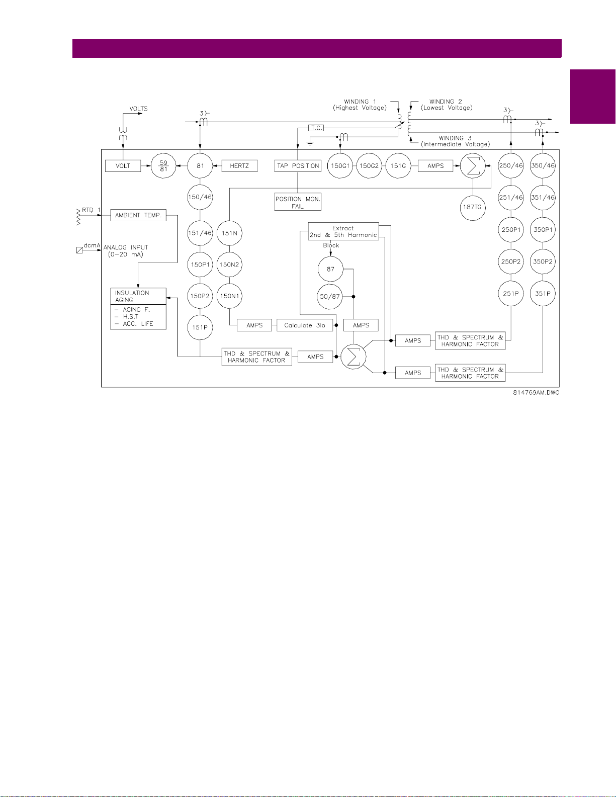
745
1
Figure 1–1: SINGLE LINE DIAGRAM
GE Power Management 745 Transformer Management Rel ay 1-3
Page 16

1
1.1 INTRODUCTION 1 PRODUCT OVERVIEW
1.1.3 ORDER CODES
745
W2 P5
745
TRANSFORMER
MANAGEMENT
®
RELAY
WINDINGS PER PHASE
W2=2WINDING
W3=3WINDING
PHASE CURRENT INPUT RATINGS
WINDING
P1
P5
P15
P51
P115
P151
P155
P511
P515
P551
1
=
1A
=
5A
=
1A
=
5A
=
1A
=
1A
=
1A
=
5A
=
5A
=
5A
1A
5A
5A
1A
1A
5A
5A
1A
1A
5A
3
(1 A)
(5 A)
—
—
5A
1A
5A
1A
5A
1A
G5
LO
L
AR
GROUND CURRENT INPUT RATINGS
WINDING
1/222/3
G1
=
1A
G5
G15
G51
=
=
=
5A
1A
5A
1A
5A
5A
1A
CONTROL POWER
LO = 24-60 Vdc
20-48 Vac @ 48-62 Hz
HI = 90-300 Vdc
70-265 Vac @ 48-62 Hz
OPTIONS
A = ANALOG INPUT/OUTPUTS
L = LOSS OF LIFE
R = RESTRICTED GROUND FAULT
Figure 1–2: 745 ORDER CODES
745ORDER.CDR
1-4 745 Transformer Management Relay GE Power Management
Page 17

1 PRODUCT OVERVIEW 1.2 TECHNICAL SPECIFICATIONS
1.2 TECHNICAL SPECIFICATIONS 1.2.1 APPLICABILITY
Transformers: 2 Winding or 3 Winding
Frequency: 50 or 60 Hz nominal
(frequency tracking allows operation from 2 to 65 Hz)
CONTROL POWER (POWER SUPPLY)
Options: LO/HI (specified when ordering)
LO Range: DC = 20 to 60 V; AC = 20 to 48 V @ 48 to 62 Hz
HI Range: DC = 90 to 300 V; AC = 70 to 265 V @ 48 to 62 Hz
Power: 30 VA nominal, 40 VA maximum
Fuse (not accessible): Hi-Volt: Current rating: 3.15 A
Type: 5 × 20 mm Slow-Blow Littelfuse, High Breaking Capacity
Model #: 2153.15
Low-V olt: C urrent rating: 3.15 A
Type: 5 × 20 mm Slow-Blow Littelfuse, High Breaking Capacity
Model #: 2153.15
PHASE CURRENT INPUT
Source CT: 1 to 50000 A primary / 1 or 5 A secondary
Relay Input: 1 A or 5 A (specified when ordering)
Burden: Less than 0.2 VA at rated load per phase
Conversion Range: 0.02 to 46 × CT
Accuracy: at < 4 x CT: ± 0.25% of 4 × CT (± 0.01 × CT)
at ≥ 4 x CT: ± 0.5% of 46 × CT (± 0.2 × CT)
Overload Withstand: 1 second at 80 times rated current
2 seconds at 40 times rated current
continuous at 3 times rated current
1
1.2.2 INPUTS
GROUND CURRENT INPUT
Source CT: 1 to 50000 A primary / 1 or 5 A secondary
Relay Input: 1 A or 5 A (specified when ordering)
Burden: Less than 0.2 VA at rated load
Conversion Range: 0.02 to 46 × CT
Accuracy: at < 4 × CT: ± 0.25% of 4 x CT (± 0.01 × CT)
at ≥ 4 × CT: ± 0.5% of 46 x CT (± 0.2 × CT)
Overload Withstand: 1 second at 80 times rated current
2 seconds at 40 times rated current
continuous at 3 times rated current
VOLTAGE INPUTS
Source VT: 2 to 600 kV / 60 to 120 V
Source VT Ratio: 1 to 5000 in steps of 1
Relay Input: 60 V to 120 V phase-neutral
Burden: Less than 0.025 VA at 120 V
Max. Continuous: 273 V
Accuracy: ± 1% of 2 × VT (± 0.02 × VT)
LOGIC INPUTS (16)
Dry Contacts: 1000 Ω maximum ON resistance (32 V DC at 2 mA provided by 745)
Wet Contacts: Inputs 1 to 16: 30 to 300 V DC at 1.5 mA
GE Power Management 745 Transformer Management Rel ay 1-5
Page 18

1.2 TECHNICAL SPECIFICATIONS 1 PRODUCT OVERVIEW
ANALOG INPUT
Type: DC mA
1
Ranges: 0-1 mA, 0-5 mA, 0-10 mA, 0-20 mA, or 4-20 mA (programmable)
Input Impedance: 375 Ω ± 10%
Conversion Range: 0 to 21 mA
Accuracy: ± 1% of full scale (based on input range)
TAP POSITION
Type: resistance (ohms)
Range: 0 to 500 Ω or 0.5 to 5.0 kΩ
Bias Current: 1 mA or 10 mA (based on input range)
Accuracy: ± 1% of full scale (based on input range)
RTD
Type: 3 wire
RTD Type 100 Ω Platinum (DIN.43760)
100 Ω Nickel
120 Ω Nickel
IRIG-B INPUT
Amplitude-Modulated: 1.0 to 10 V pk-pk
DC Shift: TTL
Input Impedance 70 to 100 kΩ
PERCENT DIFFERENTIAL PROTECTION
Operating Current Pickup: 0.05 to 1.00 in steps of 0.01 x CT
Dropout Level: 97 to 98% of Pickup
SLOPE-1 Range: 15% to 100% in steps of 1
SLOPE-2 Range: 50% to 200% in steps of 1
KP (SLOPE-1 Kneepoint): 1.0 to 20.0 in steps of 0.1 x CT
Harmonic Restraint: 0.1% to 65.0% in steps of 0.1
Operate Time: Solid State Output: Pickup < 1 x CT: 42 to 52 ms
1 x CT < Pickup < 1.1 × kneepoint: 34 to 44 ms
Pickup > 1.1 × kneepoint: 26 to 36 ms
Relay Outputs 2-5: Pickup < 1 x CT: 46 to 56 ms
1 x CT < Pickup < 1.1 × kneepoint: 38 to 48 ms
Pickup > 1.1 × kneepoint: 30 to 40 ms
INSTANTANEOUS DIFFERENTIAL OVERCURRENT
Pickup Level: 3.00 to 20.00 in steps of 0.01 x CT
Dropout Level: 97 to 98% of Pickup
Level Accuracy: Per current input
Operate Time: Solid State Output: at 1.2 x pickup: 22 to 30 ms
at 2.0 x pickup: 18 to 26 ms
at 4.0 x pickup:11 to 19 ms
Relay Outputs 2-5: at 1.2 x pickup: 28 to 36 ms
at 2.0 x pickup: 24 to 32 ms
at 4.0 x pickup: 17 to 25 ms
1.2.3 PROTECTION ELEMENTS
1-6 745 Transformer Management Relay GE Power Management
Page 19

1 PRODUCT OVERVIEW 1.2 TECHNICAL SPECIFICATIONS
PHASE / NEUTRAL / GROUND / NEGATIVE SEQUENCE TIME OVERCURRENT
Pickup Level: 0.05 to 20.00 in steps of 0.01 x CT
Dropout Level: 97 to 98% of Pickup
Curve Shape: ANSI Extreme ly/Very/Moderately/Normally Inverse;
Definite Time (0.1 s base curve);
IEC Curve A/B/C and Short;
FlexCurve™ A/B/C (programmable curves);
IAC Extreme/Very /In ve rse /Short
Curve Multiplier Time Dial: 0.5 to 30 for ANSI, IAC & Flex Curves™ in steps of 0.1 s;
0.05 to 100.00 for IEC curves in steps of 0.01
Reset Type: Instantaneous or Linear
Level Accuracy: Per current input
Timing Accuracy: at ≥ 1.03 × pickup: ± 3% of trip time or ± 20 ms (whichever is greater)
PHASE / NEUTRAL / GROUND / NEGATIVE SEQUENCE INSTANTANEOUS OVERCURRENT
Pickup Level: 0.05 to 20.00 in steps of 0.01 × CT
Dropout Level: 97 to 98% of Pickup
Time Delay: 0 to 60000 in steps of 1 ms
Level Accuracy: Per current input
Operate Ti me: Solid State Output: at 1.2 × pickup: 22 to 30 ms
at 2.0 × pickup: 18 to 26 ms
at 4.0 × pickup: 11 to 19 ms
Relay Outputs 2-5: at 1.2 × pickup: 28 to 36 ms
at 2.0 × pickup: 24 to 32 ms
at 4.0 × pickup: 17 to 25 ms
1
UNDERFREQUENCY (2 ELEMENTS)
Operating Current Pickup: 0.05 to 1.00 in steps of 0.01 × CT
Operating Voltage Pickup 0.10 to 0.99 in steps of 0.01 × VT
Pickup Level: 45.00 to 59.99 in steps of 0.01 Hz
Dropout Level: Pickup + 0.03 Hz
Time Delay: 0.00 to 600.00 s in steps of 0.01 s
Signal Source: Winding 1 phase A current / voltage
Level Accuracy: ±0.02 Hz
Operate Time: Solid State Output: at 3% beyond pickup: 120 to 150 ms
Relay Outputs 2 to 5: at 3% beyond pickup: 125 to 155 ms (delay set at 0.0 sec.)
FREQUENCY RATE OF CHANGE (4 ELEMENTS)
Operating Current Pickup: 0.05 to 1.00 in steps of 0.01 × CT
Operating Voltage Pickup 0.10 to 0.99 in steps of 0.01 × VT
Pickup Level: 45.00 to 59.99 in steps of 0.01 Hz
Dropout Level: Pickup + 0.03 Hz
Rate 1/2/3/4: 0.1 to 5.0 in steps of 0.1 Hz/sec.
Dropout Level: Pickup + 0.07 Hz/sec.
Signal Source: Winding 1 phase A current / voltage
Level Accuracy: ±0.02 Hz
Operate Time: The operate time of the fr equ ency trend elemen t is va riable a nd is de penden t on t he deca y
rate setting and the supervision frequency level.
GE Power Management 745 Transformer Management Rel ay 1-7
Page 20

1.2 TECHNICAL SPECIFICATIONS 1 PRODUCT OVERVIEW
OVERFREQUENCY (1 ELEMENT)
Operating Current Pickup: 0.05 to 1.00 in steps of 0.01 × CT
1
Operating Voltage Pickup 0.10 to 0.99 in steps of 0.01 × VT
Pickup Level: 50.01 to 65.00 in steps of 0.01 Hz
Dropout Level: Pickup – 0.03 Hz
Time Delay: 0.00 to 600.00 s in steps of 0.01 s
Signal Source: Winding 1 phase A current / voltage
Level Accuracy: ±0.02 Hz
Operate Time: Solid State Output: at 3% beyond pickup: 120 to 150 ms
Relay Outputs 2-5: at 3% beyond pickup: 125 to 155 ms (delay set to 0.0 s)
OVEREXCITATION ON VOLTS/HERTZ (2 ELEMENTS)
Operating Voltage Pickup: 0.10 to 0.99 in steps of 0.01 × VT
Pickup Level: 1.00 to 4.00 in steps of 0.01 V/Hz
Curve Shape: Definite Time (0.1 sec. base curve);
IEC Curve A/B/C
Time Delay: 0.00 to 600.00 s in steps of 0.01 s
Reset Delay: 0.0 to 6000.0 s in steps of 0.1 s
Signal Source: Voltage
Range: 10 to 65 Hz
Level Accuracy: ±0.02 V/Hz
Operate Ti me: Solid State Output: at 1.10 × pickup: 165 to 195 ms
Relay Outputs 2-5: at 1.10 × pickup: 170 to 200 ms (delay set to 0.0 s)
OVEREXCITATION ON 5TH HARMONIC LEVEL
Operating Current Pickup: 0.03 to 1.00 in steps of 0.01 × CT
Pickup Level: 0.1 to 99.9 in steps of 0.1%
Dropout: 95% of pickup
Time Delay: 0 to 60000 s in steps of 1 s
Signal Source: All phase currents
Operate Ti me: Solid State Output: at 1.10 × pickup: 20 to 120 ms
Relay Outputs 2-5: at 1.10 × pickup: 25 to 125 ms (delay set at 0.0 s)
INSULATION AGING: HOTTEST-SPOT LIMIT
Pickup Level: 50 to 300 in steps of 1°C
Delay: 0 to 60000 in steps of 1 min.
INSULATION AGING: AGING FACTOR LIMIT
Pickup Level: 1.1 to 10.0 in steps of 0.1
Delay: 0 to 60000 in steps of 1 min.
INSULATION AGING: LOSS OF LIFE LIMIT
Pickup Level: 0 to 20000 in steps of 1 x 10 h
1-8 745 Transformer Management Relay GE Power Management
Page 21

1 PRODUCT OVERVIEW 1.2 TECHNICAL SPECIFICATIONS
1.2.4 OUTPUTS
Analog Outputs (7)
Output Range: 0-1 mA, 0-5 mA, 0-10 mA, 0-20 mA, or 4-20 mA
Maximum Load: 0-1 mA: 10 kΩ
4-20 mA: 600 Ω
Isolation: Fully isolated
Accuracy: ± 1% of full scale
Solid State Output
Maximum Ratings: Make & Carry 15 A at 250 V DC for 500 ms
Output Relays
Configuration: 2-5 TRIP: Form A (breaker trip rated)
6-8 AUXILIARY : Form C
9 SELF-TEST: Form C
Contact Material: silver alloy
Max Ratings: 300 V AC, 250 V DC, 15 A, 1500 VA
RELAYS: 2-5 TRIP RELAYS: 6-8 AUXILIARY, 9 SELF-TEST
VOLTAGE MAKE/CARRY
DC
Resistive
DC
Inductive
L/R = 40 ms
AC
Resistive
AC Inductive
PF = 0.4
30 V DC 20 A 40 A 10 A 300 W DC
125 V DC 20 A 40 A 0.8 A 300 W 125 V DC 10 A 30 A 0.5 A 62.5 W
250 V DC 20 A 40 A 0.4 A 300 W 250 V DC 10 A 30 A 0.3 A 75 W
30 V DC 20 A 40 A 5 A 150 W DC
125 V DC 20 A 40 A 0.3 A 150 W 125 V DC 10 A 30 A 0.25 A 31.3 W
250 V DC 20 A 40 A 0.2 A 150 W 250 V DC 10 A 30 A 0.15 A 37.5 W
120 V AC 20 A 80 A 20 A 5000 VA AC
240 V AC 20 A 80 A 20 A 5000 VA 240 V AC 10 A 30 A 10 A 2770 VA
120 V AC 20 A 80 A 8 A 5000 VA AC Inductive
240 V AC 20 A 80 A 7 A 5000 VA 240 V AC 10 A 30 A 3 A 750 VA
CONTINUOUS
MAKE/
CARRY 0.2s
BREAK MAX
LOAD
VOLTAGE MAKE/CARRY
30 V DC 10 A 30 A 10 A 300 W
Resistive
30 V DC 10 A 30 A 5 A 150 W
Inductive
L/R = 40 ms
120 V AC 10 A 30 A 10 A 2770 VA
Resistive
120 V AC 10 A 30 A 4 A 480 VA
PF = 0.4
CONTINUOUS
MAKE/
CARRY 0.2s
BREAK MAX
LOAD
1
COMMUNICATIONS
All Ports: 300 to 19200 baud, programmable parity, Modbus RTU protocol, DNP
CLOCK
Resolution: 1 ms
Accuracy with IRIG-B: ±1 ms
without IRIG-B: ±1 minute/month
Backup Battery Life: 10 years continuous use
HARMONICS
Individual Range: 0.00 to 99.9%
Accuracy: ±1% of Full Scale @ 0.5 x CT
THD Range: 0.00 to 99.9%
Accuracy: ±1% of Full Scale @ 0.5 x CT
OPERATING ENVIRONMENT
Operating Temperature Range:–40°C to +60°C
Ambient Storage Temperature: –40
°
C to +80°C
Humidity: up to 90% non-condensing
Altitude: 2000 m
Pollution degree: II
GE Power Management 745 Transformer Management Rel ay 1-9
Page 22

1.2 TECHNICAL SPECIFICATIONS 1 PRODUCT OVERVIEW
CASE
Fully drawout unit (automatic CT shorts); Seal provision; Dust tight door; Panel or 19" rack mount
1
Weight (case & relay): 18 lbs., 6 oz.
IP class: X0
PRODUCTION TESTS
Thermal: Operational test at ambient then increasing to 60 °C
Dielectric Strength: Per IEC 255-5 and ANSI/IEEE C37.90
On CT inputs, VT inputs, Control Power inputs, Switch inputs, and Relay outputs
(2 kV for 1 second)
TYPE WITHSTAND TESTS
Fast Transient: per ANSI/IEEE C37.90.1 (5 kV)
per IEC 255-22-4 (4 kV)
Insulation Resistance: per IEC 255-5 (500 V DC, 2000 MΩ)
Dielectric Strength: per IEC 255-5 and ANSI/IEEE C37.90 (2 kV at 60 Hz for 1 minute)
Surge Immunity: per EN 61000-4-5 (common mode 4 kV, differential modes 2 kV)
per ANSI/IEEE C37.90.1, IEC 255-22-1, and Ontario Hydro A-28M-82
Voltage Dips: per IEC 1000-4-1 (0%, 40%)
Electrostatic Discharge: per IEC 255-22-2 (8/15 kV)
Power Freq uency/
Magnetic Field Immunity: per EN 61000-4-8
Damp Heat (Cyclic Humidity) per IEC 68-2-30 (6 days)
Temperature Cycle: –40°C, +60°C
Mechanical Stress 2 g
Make and Carry Rating 30 A
Current Withstand: per ANSI/IEEE C37.90 (40 × rated A for 2 seconds, 80 × rated A for 1 second)
RFI Radiated Immunity: per IEC 255-22-3 (160 MHz, 460 MHz)
per EN 61000-4-3 (10 V/m)
RFI Conducted Immunity: per EN 61000-4-6 (10 V)
RFI Conducted/Radiated
Emission: per EN 55011 / CISPR 11 FCC Part 15
APPROVALS
CSA: CSA approved
CE: Conforms to IEC 1010-1 / EN 50082-2
UL: UL approved
ISO: Manufactured under ISO9001 registered program
It is recommended that all 745 re lays be powered up at least once per year to avoid deterioration of electrolytic capacitors in the power supply.
NOTE
Specifications subject to change without notice.
1-10 745 Transformer Management Relay GE Power Management
Page 23

2 GETTING STARTED 2.1 USING THE FRONT PANEL DISPLAY
2 GETTING ST ARTED 2.1 USING THE FRONT PANEL DISPLAY 2.1.1 MANEUVERING
The following procedure describes how to maneuver through the 745 setpoints and actual values.
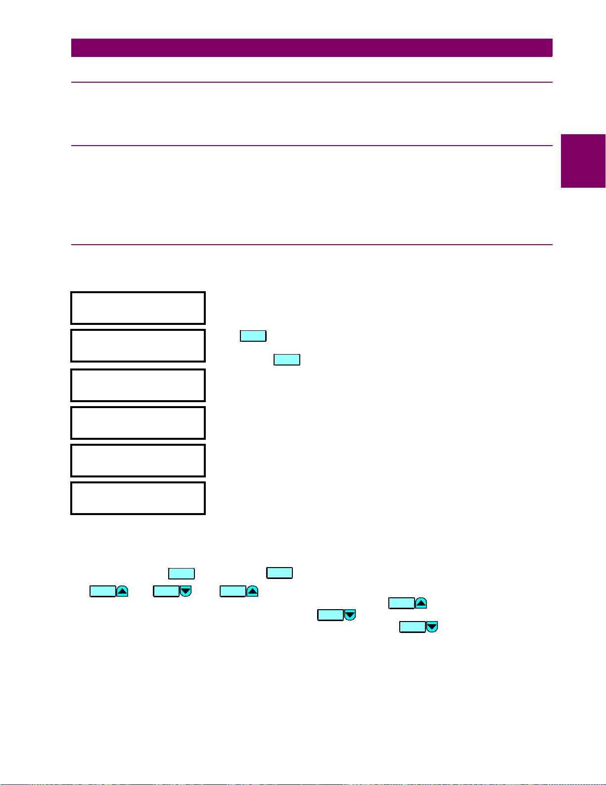
yy SETPOINTS HAVE NOT
yy BEEN PROGRAMMED!
yy ACTUAL VALUES
yy A1 STATUS
yy SETPOINTS
yy S1 745 SETUP
yy SETPOINTS
yy S2 SYSTEM SETUP
y PASSCODE
y[ENTER] for more
y END OF PAGE S1
y
When powered on successfully, the SELF-TEST ERROR and MESSAGE
indicators will be on with thi s mess age on th e display. It indicates that the 745
is in the
Not Programmed
state and safeguards against the installation of a relay
whose setpoints hav e not been entered. This message wil l remain until the
relay is explicitly put in the
Programmed
state.
Press any front panel k ey onc e an d the hea der for th e firs t ac tua l val ues pag e
appears. This page con tains syst em and relay status inf ormation. Repe atedly
press the key to display the 2
headers. Press the key once more to return to the 1
ACTUAL
ACTUAL
nd
, 3rd, and 4th actual values page
st
actual values
page header. There are 4 actual values pa ges in all, numbered from A1 (the
'A' prefix indicating that it is an actual va lues page) to A4. Actual va lues page
headers, as with setpoint page headers, h ave double scroll bars on the left
side of the message.
Press the key an d the header for the first page of s etpoints appears.
SETPOINT
This page contains setpoints to configure the 745 relay.
Press the ke y to move to the next setpoi nts page. This p age contains
setpoints for entering the characteristics of the power transformer being
protected. Repeated ly press the key to display the 3
SETPOINT
SETPOINT
rd
, 4th, 5th and 6
page headers and then back to the fir st setpoints page he ader. As you have
discovered, there are 6 setp oint pag es in all, nu mbe red from S1 ( the 'S' prefix
indicating that it is a setpoint page) to S6.
From the page one header of setpoints, press the key once to
MESSAGE
display the first sub-header. Setpoints under this sub-header are related to
passcode security. Note that the lower line of every sub-header message
[ENTER] for more
reads
Press the key repeatedly and display the remaining sub-header
MESSA GE
and that there is a single scroll bar on the left side.
messages in this page. The last message appears as shown.
2
th
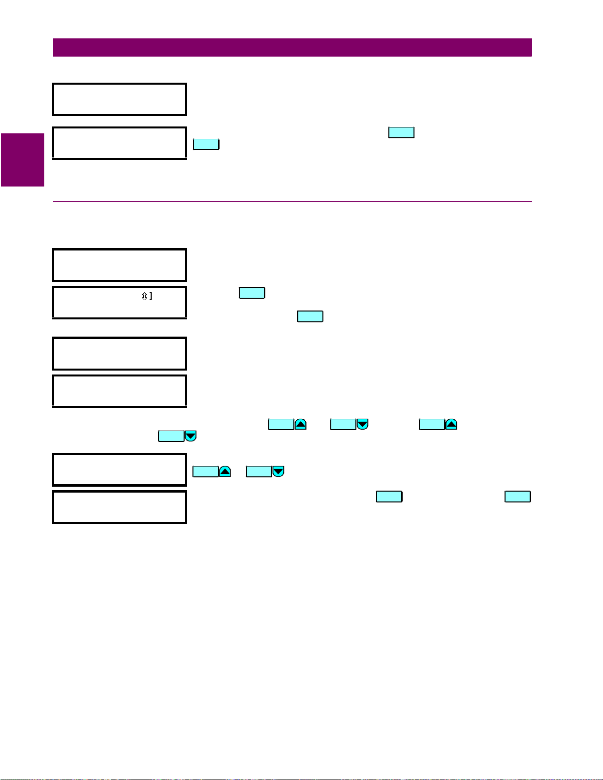
y PREFERENCES
y[ENTER] for more
By pressing the key repeatedly, move to the second sub-header
message. Setpoints unde r this sub-header me ssage allow the user to sp ecify
MESSAGE
keypad and display operati on pre fer en ces.
BEEPER:
Enabled
Press to display the first setpoint under the preferences sub-header. All
setpoint and actual value messages have two parts. The first part (
ESCAPE
BEEPER:
), is
displayed in uppercase and followed by a colon. This is the name or
description of the data. The second part (
Enabled
), either starts with an
uppercase character followed by lowercase characters or is a number followed
by units. This second part is the present value of the data.
DEFAULT MESSAGE
INTENSITY:25%
To view the rem aining setpoints a ssociated with the pre ferences sub-heade r,
repeatedly press the key. The last message appears as shown.
MESSA GE
GE Power Management 745 Transformer Management Relay 2-1
Page 24

2.1 USING THE FRONT PANEL DISPLAY 2 GETTING STARTED
ESCAPE
Let us review how we got to this last message.
1. First, we started at the setpoints page header
S1 745 SETUP
2. We then moved to the second sub-header message under page S1, which is
pressed the key .
ENTER
.
PREFERENCES
3. We then moved to the last message in this group.
A path can be used as a means of spec ifying wher e a mess age is loca ted in the 745 re lay. For this last mes-
2
sage, the path would be
S1 745 SETUP / PREFERENCES / DEFAULT MESSAGE INTENSITY
. For the purposes of this
manual, we will refer to messages in this manner. Press the key to return to the preferences sub-header
message. Pressing the key from any of the messages under a sub-header will return the display to that
sub-header message. From a sub-header message, the repeated pressing of moves the display
ESCAPE
MESSAGE
through the list of sub-header messages to the page header. As an alternative, you could press the key
and move directly to the next page.
, and we
SETPOINT
2-2 745 Transformer Management Relay GE Power Management
Page 25
2 GETTING STARTED 2.2 CHANGING SETPOINTS
2.2 CHANGING SETPOINTS 2.2.1 DESCRIPTION
There are several different classes of setpoints, distinguished by the way their values are displayed and edited.
This section describes how to edit the values used by all setpoint classes.
2.2.2 INSTALLING THE SETPOINT ACCESS JUMPER
Hardware and passco de security features are design ed to provide protection against unauthorized setpoint
changes. Since we wi ll be pr og ra mmi ng new se tpoi nts u si ng t he f ro nt p ane l k eys , a h ar dwa re ju mpe r mus t b e
installed across the se tpoint access termin als (D9 and D10) on the back of the relay case. A keys witch may
also be used acr oss these termina ls to enabl e setpoi nt acce ss. Attemp ts to enter a new setpoin t via th e front
panel without this connection will be unsuccessful.
2.2.3 NUMERICAL SETPOINTS
Each numerical setpoint has its own minimum, maximum, and increment value associated with it. These
parameters define what values are acceptable for a setpoint.
NOMINAL VT SECONDARY
VOLTAGE: 120.0 V
y MINIMUM: 60.0
y MAXIMUM: 120.0
Select the
setpoint message
Press . The following context sensitiv e flash mes sages will sequent ially
appear for several seconds each. For the case of a numerical setpoint
message, the key displays the minimum, maximum, and step value.
S2 SYSTEM SETUP / VOLTAGE INPUT / NOMINAL VT SECONDARY VOLTAGE
HELP
HELP
y IN STEPS OF:
y 0.1
y PRESS (0)-(9) OR
y VALUE
2
yy PRESS [ENTER] TO
yy STORE NEW VALUE
y END OF PAGE S1
y
Two methods of editing and storing a numerical setpoint value are available.
0
1.
to 9 and the decimal key:
The relay numeric keypad works the same as that of any electronic calculator.
A number is entered one digit at a time. The leftmost digit is entered first and the rightmost digit is entered
last. Pressing the key, before the key, returns the original value to the display.
VALUE VALUE VALUE
2.
and :
ESCA PE
The k ey increments the displayed value, by the step value, up to the
maximum value all owe d. W hi le at the maximum val ue, pres si ng the key ag ain will allow setpoin t
selection to co ntinue from th e minimum v alue. The key decrement s the disp layed value, by the
step value, down to the minimum value. Again, continuing to press the key while at the minimum
ENTER
VALUE
VALUE
VALUE
value will continue setpoint selection from the maximum value.
GE Power Management 745 Transformer Management Relay 2-3
Page 26
2.2 CHANGING SETPOINTS 2 GETTING STARTED
VALUE
NOMINAL VT SECONDARY
VOLTAGE
yy NEW SETPOINT
yy HAS BEEN STORED
2
As an example, let’s set the nomin al VT seco ndary voltag e setpoint to 69.3 V.
Press the appropriate numeric keys in the sequence ‘
6 9 . 3
message will change as the digits are being entered.
Editing changes are no t registered until the key is pressed. Pr ess the
ENTER
key to store the new value in memory. This flash message momentarily
ENTER
appears to confirmation the storing process. If 69.28 were entered, the value is
automatically rounded to 69.3, since the step value for this setpoint is 0.1.
2.2.4 ENUMERATION SETPOINTS
Enumeration setpoi nts have data values which are part of a se t, whose members are explicitl y defined by a
name. A set is comprised of two or more members.
PHASE SEQUENCE
Move to message
S2 SYSTEM SETUP / TRANSFORMER / PHASE SEQUENCE
ABC
yy PRESS [VALUE
MAKE SELECTION
yy
Ú
Ú
] TO
Press the key and the follow ing context sensitive fl ash messages will
sequentially appear for several seconds each. For the case of an enumeration
setpoint message, the key displays the number of selections in the
HELP
HELP
enumeration.
PRESS [ENTER]
yy
STORE NEW VALUE
yy
TO
‘. The display
.
FOR FURTHER HELP
yy
REFER TO MANUAL
yy
Enumeration type values are c hanged using the and keys. The key displa ys the
next selection while the key displays the previous selection.
INPUT 1 FUNCTION:
ENABLED
NEW SETPOINT
yy
HAS BEEN STORED
yy
VALUE
As an example we may need to set the phase sequence to ACB. Press
VALUE VALUE
or until the proper selection is displayed.
Editing changes are not registered until is pressed. Pressing
stores the new va lue in mem ory. This flash message mo mentarily appears to
VALUE
ENTER ENTER
VALUE
confirm the storing process.
2-4 745 Transformer Management Relay GE Power Management
Page 27

2 GETTING STARTED 2.2 CHANGING SETPOINTS
ENTER
VALUE
2.2.5 TEXT SETPOINTS
Text setpoints have data values which are fixed i n length, but user defined in char acter. T hey may be comprised of upper case letters, lower case letters, numerals, and a selection of special characters.
OUTPUT 3 NAME:
Trip 2
Move to the
setpoints message. The name of the OUTPUT 3 relay is going to be changed in
S5 OUTPUTS \ OUTPUT RELAYS \ OUTPUT RELAY 3 \ OUTPUT 3 NAME
this section.
yy PRESS [ENTER]
TO
yy BEGIN TEXT EDIT
yy PRESS [VALUE
Ú
Ú
]
Press the key and th e following context sensitive flas h messages will
sequentially app ear for several secon ds each. For the case o f a text setpoint
message, the key displays how to edit and store a new value.
TO
HELP
HELP
yy CHANGE CHARACTER
yy PRESS [ENTER]
TO
yy STORE CHARACTER
yy AND ADVANCE
TO
yy NEXT POSITION
yy FOR FURTHER HELP
yy REFER TO MANUAL
The editing and stori ng of a text value is accomp lished with the use of the , , , and
ESCA PE
keys.
OUTPUT 2 NAME:
Trip 2
OUTPUT 3 NAME:
INST DIFF TRIP
The text entered he re should be mo re descriptive t o this output relay. For this
example let us rename output relay as
INST DIFF TRIP
solid cursor (z) will appear in the first character position.
Press or key until the character 'I' is di splayed in the first
VALUE VALUE
position. Now press the key to store the character and advance the
ENTER
VALUE VALUE
. Press the key and a
ENTER
cursor to the next position. Change the second character to a ‘N’ by again
pressing the or key. Store this change by pressing the
ENTER
key again. Continue entering characters in this way until all the
characters in
character. If a character is entered i ncorrectly, press the key repe atedly
VALUE
INST DIFF TRIP
are entered. Note that a space is selected like a
ENTER
until the cursor retu rns to the position of the error. Re-enter the ch aracter as
required. Once com plete, press the key to remove th e solid cursor an d
ESCAPE
view the result.
2
GE Power Management 745 Transformer Management Relay 2-5
Page 28
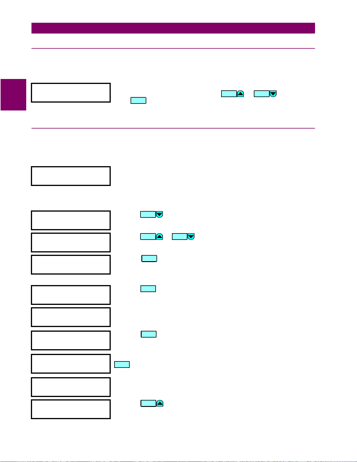
2.3 SECURITY 2 GETTING STARTED
2.3 SECURITY 2.3.1 INSTALLATION
Note that the relay is defau lted to the
Setpoints Not Programmed
state before it le aves the factory. This safe-
guards against the instal la tio n of a r el ay whos e s etp oi nts hav e no t bee n ent er ed. In add iti on, a re lay i n the
2
Programmed
745 SETPOINTS:
Not Programmed
state blocks signaling of any output relay, and turns off the IN SERVICE indicator.
Move to the
relay in the
press . Enter
S1745SETUP\INSTALLATION\745SETPOINTS
Programmed
ENTER
state, press the or key once and
Yes
for the
VALUE VALUE
ARE YOU SURE?
message. The front pa nel IN
message. To put th e
SERVICE indicator will now turn on.
2.3.2 PASSCODE SECURITY SETUP
To guarantee that the relay se ttings cannot be tampered wit h, the user may se tup the passc ode security f eature.
a) CHANGING THE PASSCODE
SETPOINT ACCESS:
Read & Write
Move to the
S1 745 SETUP \ PASSCODE \ SETPOINT ACCESS
message cannot be edited directly. It simply indicates whether passcode
security is enabled (
disabled (
SETPOINT ACCESS:
SETPOINT ACCESS:
Read & Write
Read Only
), or passcode security is
). Each relay is shipped from the
message. This
factory with setpoint access allowed. The passcode is also defaulted to '0',
which disables the passcode security feature entirely.
CHANGE PASSCODE?
Press the key once.
MESSA GE
No
Not
CHANGE PASSCODE?
Yes
PLEASE ENTER CURRENT
PASSCODE:
PLEASE ENTER A NEW
PASSCODE:
PLEASE ENTER A NEW
PASSCODE:yyy
PLEASE RE-ENTER NEW
PASSCODE:
NEW PASSCODE
HAS BEEN STORED
CHANGE PASSCODE?
No
ALLOW ACCESS TO
SETPOINTS? No
Press the or
Press the key to begin the procedure of changi ng the passcode. The
VALUE VALUE
ENTER
key once.
displayed message will change as shown. The current passcode is '0', so
press the '0' numeric key. The relay will acknowledge the key press by
displaying 'z‘.
Press the
ENTER
key.
For this example change the passcode to '123'. Press the appropriate numeric
keys in the ‘
1 2 3
‘ sequence. The message will change as the digits are
entered, with the end result being as shown.
ENTER
Press the
key to store the new pass code and a con firmation mess age
appears. As a safety measure, the relay requires you to enter a new passcode
twice. This ensures the passcode has been entered correctly.
After pressing the appropriate numeric keys in the sequence ‘
ENTER
. This flash messa ge appears momen tarily on the displ ay and confirms
1 2 3
‘, press
the new passcode is stored in memory.
After a few seconds, the original display returns.
Press the key. As soon as a non-zero pass code is ente red, setp oint
MESSA GE
access will automatically become restricted.
2-6 745 Transformer Management Relay GE Power Management
Page 29
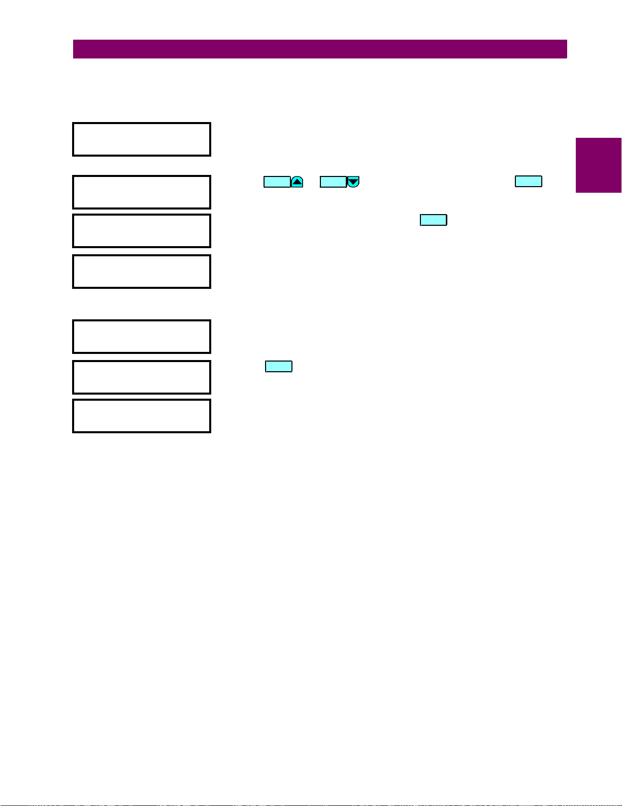
2 GETTING STARTED 2.3 SECURITY
b) DISABLING/ENABLING PASSCODE SECURITY
Suppose at some time in the future you want to alter a setpoint. In order to do this, you must first disable passcode security, make the setpoint change, and then re-enable the passcode security.
ALLOW ACCESS TO
SETPOINTS? No
PLEASE ENTER CURRENT
PASSCODE:
yy SETPOINT ACCESS
yy IS NOW ALLOWED
RESTRICT ACCESS TO
SETPOINTS? No
PLEASE ENTER CURRENT
PASSCODE:
yy SETPOINT ACCESS
yy IS NOW RESTRICTED
ALLOW ACCESS TO
SETPOINTS? No
Move to message
S1 745 SETUP \ PASSCODE \ ALLOW ACCESS TO SETPOINTS?
. It
is from here that we will disable passcode security. Please note that this
message is hidden, when the passcode security feature is disabled by
entering a passcode of ‘0’.
Press the or key once to select
VALUE VALUE
Yes
and press
ENTER
.
The
displayed message will change as shown.
Enter the current passcode and press the key. This flash message
ENTER
indicates that the keyed in v alue was acce pted and that pass code securi ty is
now disabled.
This message will app ear after a few seconds. Now that s etpoint access is
enabled, the
RESTRICT ACCESS TO SETPOINTS
the
ALLOW ACCESS TO SETPOINTS?
message. The relay’s setpoints can now
message has been rep laced by
be altered and stored . If no front panel keys are pressed for longer than 3 0
minutes, setpoint access will automatically become restricted again.
To disable set point access, immediately after setpoint edi ting, move back to
message
Yes
. Key the current passcode into the shown message.
Press the key and this message will flash on the display. It indicates
S1 745 SETUP \ PASSCODE \ RESTRICT ACCESS TO SETPOINTS?
ENTER
and enter
that passcode security is now enabled.
After a few seconds, the original display returns.
2
GE Power Management 745 Transformer Management Relay 2-7
Page 30

2
2.3 SECURITY 2 GETTING STARTED
2-8 745 Transformer Management Relay GE Power Management
Page 31

3 INSTALLATION 3.1 DRAWOUT CASE
3 INSTALLATION 3.1 DRAWOUT CASE 3.1.1 CASE DESCRIPTION
The 745 is packaged in the standard SR series arrangement, which consists of a drawout relay and a companion case. The case provides mechanical protection for the drawout po rtion, and is used to make permanent
electrical connection s to external equipment. Where required, case co nnectors are fitted with mechanisms,
such as automati c CT shortin g, to allow th e safe remova l of the rel ay from an ene rgized panel. There are n o
electronic components in the case.
3
Figure 3–1: CASE DIMENSIONS
3.1.2 PANEL CUTOUT
A 745 can be mounted a lon e or adjacent to another S R se ri es un it o n a s tan dar d 1 9” ra ck pa nel . P ane l cu tou t
dimensions for both conditio ns are as shown. When planni ng the location of your panel cutout, ensure provision is made for the front door to swing open without interference to or from adjacent equipment.
Double Panel
Single Panel
Figure 3–2: SINGLE AND DOUBLE SR RELAY PANEL CUTOUT
GE Power Management 745 Transformer Management Rel ay 3-1
Page 32

3.1 DRAWOUT CASE 3 INSTALLATION
3.1.3 CASE MOUNTING
Before mounting th e SR unit in the supporting panel , remove the rel ay portion from its case, as desc ribed in
the next section. From the front of the panel, slide the empty case into the cutout. To ensure the front bezel sits
flush with the panel, apply press ure to the bezel’s front while bending the reta ining tabs 90°. These tabs are
located on the sides and bottom of the case and appear as shown in the illustration. After bending all tabs, the
case will be securely mounted so that its relay can be inserted. The SR unit is now ready for panel wiring.
3
Figure 3–3: CASE MOUNTING
3.1.4 UNIT WITHDRAWAL AND INSERTION
TURN OFF CONTROL POWER BEFORE DRAWING OUT OR RE-INSERTING THE RELAY TO
PREVENT MALOPERATION!
CAUTION
a) RELAY WITHDRAWAL
1. Open the door by pulling from the center of its right side. It will rotate to the left about its hinges.
2. Press upward on the loc king l atch, which is locate d belo w the hand le, and ho ld in i ts rais ed positio n. The
tip of a small screwdriver may prove helpful in this operation.
3. With the latch raised, pull the center of the handle outward. Once disengaged, continue rotating the handle
up to the stop position.
Press Latch Up and Pull Handle
Rotate Handle to Stop Position
3-2 745 Transformer Management Relay GE Power Management
Page 33

3 INSTALLATION 3.1 DRAWOUT CASE
4. The locking mechanism releases wh en the stop positi on is reac hed. The r elay now s lides out o f the cas e
when pulled from its handle. To free the relay, it may be necessary to adjust the handle position slightly.
Figure 3–4: SLIDING RELAY OUT OF CASE
b) RELAY INSERTION
Any 745 can be in stalled in any 74 5 case, but cann ot be inserted int o the case of ano ther product in the S R
series. For instance, you cannot place an 745 relay into a 735 case.
3
If an attempt is made to install a relay into a non-matching case, the case configuration pin
will prevent full insertion. Applying a strong for ce in th is instance will r esult in damage t o th e
CAUTION
Even though a rel ay m ay be inser ted i nto a case , one shoul d mak e su re the model numbe r on the left s ide o f
the relay matches the requirements of the installation.
1. With the relay’s handle raised, align and slide both rolling guide pins into the case guide slots. Each rolling
2. Once fully inserted, grasp the handle from its center and rotate it down from the raised position towards the
3. As the handle is ful ly inser ted, the latch wi ll be h eard to click, l ocking th e handle in th e final position. The
c) DRAWOUT SEAL
To prevent una uthoriz ed remov al of t he draw out rela y, a wire lead seal can be i nstalled throu gh the sl ot in th e
middle of the locki ng latc h. The r elay c annot b e rem oved fro m the c ase wi th this seal i n place. Even though a
passcode or setpoint access jumper can be used to p revent entry of setpoints and stil l allow monitoring of
actual values, access to the front panel controls may still need to be restricted. As such, a separate seal can be
installed on the outside of the door to prevent it from being opened.
relay and case.
guide pin is found near the hinges of the relay’s handle.
bottom of the relay.
unit is mechanica lly held in the case by the ha ndle’s rolling pins, which cannot be ful ly lowered to the
locked position until the electrical connections are completely mated.
Figure 3–5: DRAWOUT SEAL
GE Power Management 745 Transformer Management Rel ay 3-3
Page 34

3.2 TYPICAL WIRING 3 INSTALLATION
3.2 TYPICAL WIRING 3.2.1 DESCRIPTION
Due to the many features buil t into the 745 relay, a broad range of applications ar e available to the user. As
such, it is not p ossible to present connections for all possible schemes. The information in this sectio n will
cover the importa nt aspects of inter connections, in the general areas of instrument tran sformer inputs, ot her
inputs, outputs, communications and grounding.
3.2.2 REAR TERMINAL LAYOUT
3
Figure 3–6: REAR TERMINAL LAYOUT
3-4 745 Transformer Management Relay GE Power Management
Page 35

3 INSTALLATION 3.2 TYPICAL WIRING
3.2.3 REAR TERMINAL ASSIGNMENTS
ANALOG INTERFACE OUTPUTS & GROUN D CT N2
A1 ANALOG INPUT + E1 OUTPUT 1 - SOLID STATE TRIP (+)
A2 ANALOG INPUT – E2 OUTPUT 2 - TRIP RELAY (N/O)
A3 TAP POSITION (+) E3 OUTPUT 3 - TRIP RELAY (N/O)
A4 TAP POSITION (–) E4 OUTPUT 4 - TRIP RELAY (N/O)
A5 ANALOG OUTPUT (Common) E5 OUTPUT 5 - TRIP RELAY (N/O)
A6 ANALOG OUTPUT 1 (+) E6 OUTPUT 6 - AUXILIARY RELAY (N/O)
A7 ANALOG OUTPUT 2 (+) E7 OUTPUT 6 - AUXILIARY RELAY (N/C)
A8 ANALOG OUTPUT 3 (+) E8 OUTPUT 7 - AUXILIARY RELAY (N/O)
A9 ANALOG OUTPUT 4 (+) E9 OUTPUT 8 - AUXILIARY RELAY (N/O)
A10 ANALO G O UTPUT 5 (+) E10 OUTPUT 8 - AUXILIARY RELAY (N/C)
A11 ANALOG OUTPUT 6 (+) E1 1 OUTPUT 9 - SERVICE RELAY (Common)
A12 ANALOG OUTPUT 7 (+) E12 GROUND - WINDING 2/3 CT
COMMUNICATIONS & RTD INPUTS OUTPUTS & GROUND CT N2
B1 COMPUTER RS485 (+) / RS422 (Rx +) F1 OUTPUT 1 - SOLID STATE TRIP (–)
B2 COMPUTER RS485 (–) / RS422 (Rx –) F2 OUTPUT 2 - TRIP RELAY (Common)
B3 COMPUTER RS485 (Com) / RS42 2 (C om) F3 OUTPUT 3 - TRIP RELAY (Com m on)
B4 RS422 (Tx +) F4 OUTPUT 4 - TRIP RELAY (Common)
B5 RS422 (Tx –) F5 OUTPUT 5 - TRIP RELAY (Common)
B6 EXTERNAL RS485 (+) F6 OUTPUT 6 - AUXILIARY RELAY (
B7 EXTERNAL RS485 (–) F7 OUTPUT 7 - AU XI LIARY RELAY (N/O)
B8 IRIG-B + F8 OUTPUT 7 - AUXILIARY RELAY (N/C)
B9 IRIG-B – F9 OUTPUT 8 - AUXILIARY RELAY (
B10 RTD 1 HOT F10 OUTPU T 9 - SERVICE RELAY (N/O)
B11 RTD 1 COMPE NSATION F11 OUTPUT 9 - SERVICE RELAY (N/C)
B12 RTD 1 RETURN F12 GROUND - WINDING 2/3 CT
n
LOGIC INPUTS 9-16 & VT INPUT CT INPUTS & 745 GROUNDING
C1 LOGIC INPUT 9 (+) G1 PHASE A - WINDING 1 CT
C2 LOGIC INPUT 10 (+) G2 PHASE B - WINDING 1 CT
C3 LOGIC INPUT 11 (+) G3 PHASE C - WINDING 1 CT
C4 LOGIC INPUT 12 (+) G4 PHASE A - WINDING 2 CT
C5 LOGIC INPUT 13 (+) G5 PHASE B - WINDING 2 CT
C6 LOGIC INPUT 14 (+) G6 PHASE C - WINDING 2 CT
C7 LOGIC INPUT 15 (+) G7 PHASE A - WINDING 3 CT
C8 LOGIC INPUT 16 (+) G8 PHASE B - WINDING 3 CT
C9 RESERVED G9 PHASE C - WINDING 3 CT
C10 RESERVED G10 GROUND - WINDING 1/2 CT
C11 VT INPUT
n
G11 745 FILTER GROUND
C12 VT INPUT G12 745 SAFETY GROUND
LOGIC INPUTS 1-8 & DEDICATED INPUTS CT and VT INPUTS / POWER
D1 LOGIC INPUT 1 (+) H1 PHASE A - WINDING 1 CT
D2 LOGIC INPUT 2 (+) H2 PHASE B - WINDING 1 CT
D3 LOGIC INPUT 3 (+) H3 PHASE C - WINDING 1 CT
D4 LOGIC INPUT 4 (+) H4 PHASE A - WINDING 2 CT
D5 LOGIC INPUT 5 (+) H5 PHASE B - WINDING 2 CT
D6 LOGIC INPUT 6 (+) H6 PHASE C - WINDING 2 CT
D7 LOGIC INPUT 7 (+) H7 PHASE A - WINDING 3 CT
D8 LOGIC INPUT 8 (+) H8 PHASE B - WINDING 3 CT
D9 SETPOINT ACCESS (+) H9 PHASE C - WINDING 3 CT
D10 SETPOINT ACCESS (–) H10 GROUND - WINDING 1/2 CT
n
n
n
n
n
n
n
n
n
n
D11 LOGIC POWER OUT (+) H11 CONTROL POWER (–)
D12 LOGIC POWER OUT (–) H12 CONTROL POWER (+)
n
indicates high side of CT and VT terminals
Common
Common
)
)
3
GE Power Management 745 Transformer Management Rel ay 3-5
Page 36

3
3.2 TYPICAL WIRING 3 INSTALLATION
3.2.4 TYPICAL WIRING DIAGRAMS
g
Figure 3–7: TYPICAL WIRING DIAGRAM
3-6 745 Transformer Management Relay GE Power Management
Page 37

3 INSTALLATION 3.2 TYPICAL WIRING
g
3
Figure 3–8: TYPICAL WIRING DIAGRAM FOR GENERATOR STEP-UP
GE Power Management 745 Transformer Management Rel ay 3-7
Page 38

3.2 TYPICAL WIRING 3 INSTALLATION
3.2.5 PHASE SEQUENCE AND TRANSFORMER POLARITY
For the correct op eration of many relay featu res, the phase sequence and instrument transforme r polarities
shown on the typical wiring diagram must be followed. Note the markings sh own with all instrument transformer connections. When the connections adhere to this drawing, the relay will operate properly.
3.2.6 AC CURRENT TRANSFORMER INPUTS
The 745 has eight or e leven channels for AC current inputs, each with a n isolating tran sformer and an au tomatic shorting mechan ism that acts when the r elay is withdrawn from its case. There are no internal ground
connections on the current inputs. Current transformers with 1 to 50 000 A primaries may be used.
3
CAUTION
The exact placement of a z ero-sequence CT so that ground fault current wi ll be detected is shown below.
Twisted pair cabling on the zero-sequence CT is recommended.
Verify that the relay’s nominal current of 1 A or 5 A matches the secondary rating of the connected CTs. Unmatched CTs may result in equipment damage or inadequate protection.
Figure 3–9: ZERO-SEQUENCE (CORE BALANCE) CT INSTALLATION
IMPORTANT: The relay will corr ectly mea sure up to 46 times the cu rre nt input nominal r ating.
Time overcurrent curves become horizontal lines for currents above the 46 × CT rating.
NOTE
The 745 has one voltage divider type input for AC voltages. There are no internal fuses or ground connections.
Voltage transformers up to a maximum 5000 :1 ratio may be used. The nomi nal seco ndary volt age must be i n
the 60 to 120 V range.
3-8 745 Transformer Management Relay GE Power Management
3.2.7 AC VOLTAGE INPUT
Page 39

3 INSTALLATION 3.2 TYPICAL WIRING
3.2.8 CONTROL POWER
Control power supplied to the relay must match the installed power supply range. If the
applied voltage does not match, damage to the unit may occur.
WARNING
The label found on the left side of the relay specifies its order code or model number. The installed power supply operating range will be one of the following.
LO: 25 to 60 V DC or 20 to 48 V AC
HI: 88 to 300 V DC or 70 to 265 V AC
Ensure the applie d co ntro l voltage matches the re qui reme nts of the re la y’s sw itc hi ng p ower s upp ly. For example, the HI power supply will w ork with any DC volta ge from 88 to 300 V, or any AC voltage from 70 to 265 V.
The internal fuse may blow if the applied voltage exceeds this range.
3
Figure 3–10: CONTROL POWER CONNECTION
3.2.9 LOGIC INPUTS
Correct polarity must be observed for all logic input connections or equipment damage may
result.
CAUTION
External contacts can be connected to the 16 logic inputs. As shown, these contacts can be either dry or wet. It
is also possible to use a combination of both contact types.
A dry contact has one side conne cted to ter minal D11. This is the +32 V DC voltage rail. Th e other si de of the
dry contact is connected to the required logic input terminal. When a dry contact closes, a current of 2.2 mA will
flow through the associated circu it.
A wet contact has one side c onnect ed to the posi tive termin al of an exte rnal DC pow er supply . The other side
of this contact is connected to the requ ired logic inpu t terminal. In additi on, the negative side of the external
source must be connected to the relay DC NEGATIVE rail at terminal D12. The maximum external source voltage for this arrangement is 300 V DC.
GE Power Management 745 Transformer Management Rel ay 3-9
Page 40

3.2 TYPICAL WIRING 3 INSTALLATION
3
Figure 3–11: DRY AND WET CONTACT CONNECTIONS
3.2.10 ANALOG INPUT
Terminals A1 (+) and A2 (–) are provided for the input of a current signal, from one of the following: 0-1 mA, 05 mA, 0-20 mA, or 4-20 mA transduce r outputs. This curren t signal can represen t any external quanti ty, such
as temperature, cur rent or vol tage. Be sure to o bserve po larity m arkings for correct o peration . Both te rminals
are clamped to with in 36 volts of g round with surge pr otection. As suc h, common mode vo ltages should not
exceed this limit. Shielde d wire, with only on e end of the shield gr ounded, is rec ommended to mi nimize nois e
effects. The A2 (–) terminal must be connected to the A5 (ANALOG OUTPUT COM) terminal at the 745.
3.2.11 TAP POSITION INPUT
Terminals A3 (+) and A4 (-) are provided to monitor the position of an Onload Tap Chang er from a steppedresistance posit ion indi cator de vice. Terminal A3 is connected inte rnally to a 4.3 mA curre nt source. This cur rent is used to measure the val ue of the externa l resistance. Th e 745 uses the measur ed resistanc e value to
calculate the Tap Position.
3.2.12 RTD DRIVER/SENSOR
Terminals B10 (RTD HOT), B11 (RTD COMP) and B12 (RTD RET) provide for the connection of v ariou s ty pes
of RTD devices. This connection may be made using two or three wires to the RTD. T erminal B10 is connected
internally to a 5 mA current source for energizing the RTD. Terminal B11 is connected internally to a 5 mA current source for the purpose of cancelling out the resistance of the wires connecting the RTD to the 745. Terminal B12 is the return path for the two current sources.
In the three-wire connection scheme, the connection from terminal B11 to B12 is made at the RTD. The threewire connection scheme compensates for the resistance of the wiring between the 745 and the RTD.
In the two-wire connection sch eme, the connec tion from termina l B11 to B12 is made at the terminal block on
the rear of the 745. This con necti on must not be o mitted. The two-w ire conn ectio n scheme does no t compensate for the resistance of the wiring between the 745 and the RTD.
3-10 745 Transformer Management Relay GE Power Management
Page 41

3 INSTALLATION 3.2 TYPICAL WIRING
3.2.13 OUTPUT RELAYS
Eight output relays are provided with the 74 5. Output Rela ys 2 through 5 have Form A contacts while Output
Relays 6 to 8 and the SELF-TEST relay have Form C contacts. Since Output Rela ys 2 to 5 are intended for
operating a breaker tr ip coil, the Form A co ntacts hav e higher cu rrent rati ngs than the Form C con tacts. Note
that the operating mod e of the SELF-TEST re lay is fixed, while the o ther relays can be pr ogrammed by the
user via the FlexLogic™ feature.
3.2.14 SOLID STATE TRIP OUTPUT
A high-speed solid state (SCR) output is also provided. This output is intended for applications where it is necessary to key a communications channel.
3.2.15 ANALOG OUTPUTS
The 745 provides 7 analog output channels whose full scale range can be set to one of the following ranges.
0 to 1 mA; 0 to 5 mA; 0 to 10 mA; 0 to 20 mA; 4 to 20 mA
Each analog output channel can be p rogrammed to rep resent one of the par ameters measur ed by the relay.
For details, see the setpoints chapter.
As shown in the typical wiring diagram, the analog output signals originate from terminals A6 to A12 and share
A5 as a common ret urn. Output si gnals are inter nally isolated and allow conne ction to devices which sit at a
different ground potenti al. Each analog o utput terminal i s clamped to withi n 36 V of ground. To minimize the
effects of noise, external connections should be made with shielded cable and only one end of the shield
should be grounded.
3
If a voltage output i s required, a burden resistor must be connected at the input of the ex ternal measuring
device. Ignoring the input impedance,
• If a 5 V full scale output is required with a 0 to 1 mA output channel,
• For a 0 to 5 mA channel this resistor would be 1 KΩ.
• For a 0 to 10 mA channel, this resistor would be 500 Ω.
• For a 4 to 20 mA channel this resistor would be 250 Ω.
R
LOAD
=
V
FULL SCALE
/
I
MAX
.
R
= 5V / 0.001A = 5 KΩ.
LOAD
Figure 3–12: ANALOG OUTPUT CONNECTION
GE Power Management 745 Transformer Management Relay 3-11
Page 42

3.2 TYPICAL WIRING 3 INSTALLATION
3.2.16 RS485 / RS422 COMMUNICATION PORTS
The 745 provides the user wi th two rear co mmunica tio n ports whic h may be used simu lta neously. Both implement a subset of the AEG Modicon Modbus protocol as outlined in Chapter 8: COMMUNICATIONS.
The first port, COM1, can be used in the two wire RS485 mode or the four wire RS422 mode, but will not operate in both modes at the same time. In t he RS485 mode, data t ransmission and reception are acco mplished
over a single twisted pair with transmi t a nd receive data alternating over the same two wires. These wires
should be connected to the te rm ina ls m ar ked RS 48 5. T h e RS 42 2 m ode us es th e CO M 1 te rm in als d es ig nate d
as RS485 for receive lines, and the COM1 terminals designated as RS422 for transmit lines. The second port,
COM2, is intended for th e two wire RS485 mode o nly. Through the use of these ports, cont inuous moni toring
and control from a remote computer, SCADA system or PLC is possible.
To minimize err ors from noise, the use of shielded twisted-p air wire is recom mended. Correct pola rity should
3
also be observed. Fo r instance, the rel ays must be connec ted with all B1 ter minals (labeled C OM1 RS485+)
connected together, and all B2 t erminals (labeled COM1 RS485–) connected to gether. Term inal B3 (labeled
COM1 RS485 COM) should be connected to the common wire insi de the shield. To avoid loop currents, the
shield should be gr oun ded at o ne point only. Each relay should also be daisy-chained t o the nex t i n th e l ink. A
maximum of 32 relays can be connected in this manner without exceeding driver capability. For larger systems,
additional serial channels must be added. It is also possible to use commercially available repeaters to include
more than 32 relays on a single channel. Star or stub connections should be avoided entirely.
Lightning strikes a nd ground surge current s can cause large momentary voltage differenc es between remote
ends of the communicati on link. F or this rea son, s urge prot ectio n devices are inter nally p rovided at both c ommunication ports. An isolated powe r suppl y with an optoc oupled data interfac e also acts to r educe noi se coupling. To ensure maximum reliability, all equipment should have similar transient protection devices installed.
Figure 3–13: RS485 CONNECTION
3-12 745 Transformer Management Relay GE Power Management
Page 43

3 INSTALLATION 3.2 TYPICAL WIRING
3
Figure 3–14: RS422 CONNECTION
3.2.17 RS232 FRONT PANEL PROGRAM PORT
A 9 pin RS232C seri al port is located on the fro nt panel for programming t hrough a PC. This port uses th e
same Modbus protoc ol as the two rear ports. The 745PC soft ware required to use this interfac e is included
with the relay. Cabling for the RS232 port is shown below for both 9 pin and 25 pin connectors.
Figure 3–15: RS232 CONNECTION
GE Power Management 745 Transformer Management Relay 3-13
Page 44

3.2 TYPICAL WIRING 3 INSTALLATION
3.2.18 IRIG-B
IRIG-B is a standard time code format that allows stampin g of events to be synchronized a mong connected
devices within 1 millisecond. The IRIG time code formats are serial, width-modulated codes which can be
either DC level shi fted or amplitude modulated (AM ). Third party equipment is avai lable for generating the
IRIG-B signal; this equipmen t may u se a G PS satelli te system to obtai n the tim e referenc e so th at devic es at
different geographic locations can also be synchronized.
3
GPS CONNECTION
OPTIONAL
TIME CODE
GENERATOR
(DC SHIFT OR
AMPLITUDE MODULATED
SIGNAL CAN BE USED)
IRIG-B
GPS SATELLITE SYSTEM
RG58/59 COAXIAL CABLE
+
-
TO OTHER DEVICES
745 RELAY
IRIG-B(+)
B8
IRIG-B(-)
B9
RECEIVER
814823A1.CDR
Figure 3–16: IRIG-B FUNCTION
3.2.19 DIELECTRIC STRENGTH TESTING
Dielectric strength t est was pe rf ormed on the 745 relay at the man ufa ctu rer. It is not necess ary to p er form th is
test again at the custo mer site . Howe ve r, if you wish to perfor m th is tes t, follo w in struc ti ons out li ned in S ect io n
10.3.2: DIELECTRIC STRENGTH TESTING on page 10–5.
No special ventilation requirements need to be observed during the installation of the unit.
The unit does not have to be cleaned.
NOTE
Hazard may result if the product is not used for its intended purpose.
WARNING
3-14 745 Transformer Management Relay GE Power Management
Page 45

4 FRONT PANEL OPERATION 4.1 FRONT PANEL
4 FRONT PANEL OPERATION 4.1 FRONT PANEL 4.1.1 DESCRIPTION
The front panel pr ovides a local o perator interface with a vacuum fl uorescent display, LED status indicator s,
control keys, and progra m port. The display and status indi cators update alarm and status information automatically. The control keys are used to select th e appropriate message for entering setpoints or displaying
measured values. The RS232 program port is also provided for connection with a computer running the 745PC
software.
STATUS INDICATORS AND
LOCAL CONTROL KEYS
745 STATUS SYSTEM STATUS CONDITIONS
IN SERVICE
SELF-TEST
ERROR
TEST MODE
DIFFERENTIAL
BLOCKED
LOCAL
RESET
NEXT
PROGRAM PORT
SETPOINT
ACTUAL
ESCAPE
ENTER
TRANSFORMER
DE-ENERGIZED
TRANSFORMER
OVERLOAD
LOAD-LIMIT
REDUCED
SETPOINT GROUP 1
SETPOINT GROUP 2
SETPOINT GROUP 3
SETPOINT GROUP 4
MESSAGE
VALUE
DISPLAY
TRIP
ALARM
PICKUP
PHASE A
PHASE B
PHASE C
GROUNDMESSAGE
7 89
5
4
12 3
.
6
HELP
0
4
SETPOINT ENTRY
AND MONITOR KEYS
745 Transformer Management Relay ™
g
FrontPanel.CDR
HANDLE TO WITHDRAW RELAYPROGRAM PORT INTERFACE
TO LOCAL COMPUTER
Figure 4–1: 745 FRONT PANEL
GE Power Management 745 Transformer Management Rel ay 4-1
Page 46

4.2 DISPLAY, INDICATORS, AND FRONT PORT 4 FRONT PANEL OPERATION
4.2 DISPLAY, INDICATORS, AND FRONT PORT 4.2.1 DISPLAY
All messages are dis played in Engl ish on the 40-char acter vacuu m fluorescen t display, which is visible under
varied lighting con ditions. When the keypad and displa y are not actively be ing used, the screen s equentially
displays up to 30 user-selected default messages providing system information. These messages appear after
a time of inactivity that is progra mmable by the us er. Pressing any key after defa ult messages have ap peared
will return the display to the last message displayed before the default messages appeared. Trip and alarm
condition messag es automatically overr ide default messages. Al l display pixels are i lluminated briefly durin g
power up self-testing, and can be energized by pressing when no trips or alarms are active.
Front panel indic ators are groupe d in three columns : RELAY STATUS, which provides informa tion about the
state of the 745; SYS TEM STATUS, which provides informati on about the state of the transformer an d the
power system; and CONDITIONS, which provides details about abnormal conditions that have been detected.
The color of each indicator conveys information about its importance:
GREEN (G) indicates a general condition
4
AMBER (A) indicates an alert condition
RED (R) indicates a serious alarm or warning
N E X T
4.2.2 LEDS
All indicators can be tested by pressing while no conditions are active.
a) IN SERVI CE
The IN SERVICE indicator is on when relay protection is operational.
The indicator is on only if all of the following conditions are met:
• S1 745 SETUP / INSTALLATION / 745 SETPOINTS:
• S6 TESTING / OUTPUT RELAYS / FORCE OUTPUT RELAYS FUNCTION:
• S6 TESTING / SIMULATION / SIMULATION SETUP / SIMULATION FUNCTION:
• No self-test errors which have an effect on protection have been detected
• code programming mode is inactive
• factory service mode is disabled
b) SELF-TEST ERROR
The SELF-TEST ERROR indic ator is on when any of the self-diagnostic tests , performed either at power-on or in the background during normal operation, has detected
a problem with the relay.
c) TEST MODE
N EXT
Programmed
4.2.3 STATUS INDICATORS
Disabled
Disabled
The TEST MODE indicator is on when any of the 745 testing features has been enabled.
The indicator is on if any of the following conditions are met:
• S6 TESTING/OUTPUT RELAYS/FORCE OUTPUT RELAYS FUNCTION:
• S6 TESTING/ANALOG OUTPUTS/FORCE ANALOG OUTPUTS FUNCTION:
•
S6 TESTING/SIMULATION/SIMULATION SETUP/SIMULATION FUNCTION:
• factory service mode is enabled
Enabled
Enabled
Prefault Mode / Fault Mode / Playback Mode
4-2 745 Transformer Management Relay GE Power Management
Page 47

4 FRONT PANEL OPERATION 4.2 DISPLAY, INDICATORS, AND FRONT PORT
d) DIFFERENTIAL BLOCKED
The DIFFERENTIAL BLOCKE D indicator is on when the restraine d differential protection feature is ena bled
but is being blocked from operating by any of the harmonic restraint features.
The indicator is on if the following condition is met:
•
S4 ELEMENTS / DIFFERENTIAL / HARMONIC RESTRAINT
e) LOCAL
The LOCAL indicator is on when the 745 is in local mode, i.e. the front panel RESET key is operational.
f) MESSAGE
The MESSAGE indicator is on when any element has picked up, operated, or is now in a latched state waiting
to be reset. With this indicator on, the front panel display is sequentially displaying information about each element that has detected an abnormal condition.
a) TRANSFORMER DE-ENERGIZED
The TRANSFORMER DE -ENERGIZED i ndicator is on when th e energizati on inhibit
feature has detected that the transformer is de-energized.
The indicator is on if the
detecting the transformer as de-energized
b) TRANSFORMER OVERLOAD
The TRANSFORMER OVERLOAD indicator is on when
OVERLOAD
has operated.
is blocking any phase (see scheme logic)
4.2.4 SYSTEM STATUS INDICATORS
S4 ELEMENTS/DIFFERENTIAL/ENERGIZATN INHIBIT
S4 ELEMENTS/XFORMER
feature is
4
c) LOAD-LIMIT REDUCED
The LOAD-LIMIT REDUCED i ndicator is on when the adaptive harmonic factor correction feature is detectin g enou gh h armonic cont ent to red uce th e load rati ng of th e
transformer. The indicator is on if
Enabled
DERATING ESTIMATION
d) SETPOINT GROUP 1
The SETPOINT GROUP 1 indica tor is on when the ac tive se tpoint group is 1. This indi cator fla shes whe n this
setpoint group is being edited.
e) SETPOINT GROUP 2
The SETPOINT GROUP 2 indica tor is on when the ac tive se tpoint group is 2. This indi cator fla shes whe n this
setpoint group is being edited.
f) SETPOINT GROUP 3
The SETPOINT GROUP 3 indica tor is on when the ac tive se tpoint group is 3. This indi cator fla shes whe n this
setpoint group is being edited.
g) SETPOINT GROUP 4
The SETPOINT GROUP 4 indica tor is on when the ac tive se tpoint group is 4. This indi cator fla shes whe n this
setpoint group is being edited.
is
S2 SYSTEM SETUP/HARMONIC DERATING/HARMONIC
and the harmonic derating function is below 0.96.
GE Power Management 745 Transformer Management Rel ay 4-3
Page 48

4.2 DISPLAY, INDICATORS, AND FRONT PORT 4 FRONT PANEL OPERATION
4.2.5 CONDITION INDICATORS
a) TRIP
Trip
The TRIP indicato r is on when any output relay selected to be o f the
operated.
b) ALARM
The ALARM indicator is on wh en any output relay selected to be of the
has operated.
c) PICKUP
The PICKUP indicator is on w hen any elem ent h as pi cke d up. W ith this ind ic ato r on,
the front panel display is sequentially displaying information about each element that
has picked up.
d) PHASE A (B/C)
type has
Alarm
type
4
e) GROUND
The GROUND indicator is on when ground is involved in the condition detected by any element that has picked
up, operated, or is now in a latched state waiting to be reset.
Use the front panel progra m port for RS232 communications with the 745. As described in Section 3.2.17:
RS232 FRONT PANEL PROGRAM PORT on page 3–13, all that is required is a connection between the relay
and a computer running the 745PC software. For con tinuous monitoring of mul tiple relays, either the COM 1
RS485/RS422 port or the COM2 RS485 port should be used.
The PHASE A (B/C) indic ator is on when phas e A (B/C) is involv ed in the conditio n
detected by any element t hat has picked up, opera ted, or is now in a latched stat e
waiting to be reset.
4.2.6 PROGRAM PORT
Figure 4–2: PROGRAM PORT
4-4 745 Transformer Management Relay GE Power Management
Page 49

4 FRONT PANEL OPERATION 4.3 KEYPAD
MESSAGE
ESCA PE
4.3 KEYPAD 4.3.1 SETPOINT KEY
Setpoints are arranged into groups of rela ted messages called s etpoint pages. Each time is pres sed,
the display advances to the first message of the next setpoints page. Pressi ng while in the middle of a
SETPOINT
setpoints page advan ces the displ ay to the beginn ing of the next set point page. Press ing whil e in the
SETPOINT
SETPOINT
middle of an actual va lues page returns the displa y to the last setpoint message viewed. If the display has
timed out to the default messages, pressing returns the display to the last viewed setpoin t message.
MESSA GE MESSAGE
The / keys move between messages within a page.
SETPOINT
4.3.2 ACTUAL KEY
Measured valu es and collected data messages are arran ged into groups of r elated messages called actual
values pages. Each time is pressed, the display advances to the first message of the next actual values
page. Pressing while in the mid dle of an actual values page a dvances the disp lay to the begi nning of
ACTUAL
the next page. Pressing while in the middle of a setpoints page returns the display to the last actual values message viewed. If the display has timed out to the default messages, pressing returns the display
to the last viewed ac tual values message. The / keys mo ve between messages within a
ACTUAL
ACTUAL
ACTUAL
MESSAGE
page.
4.3.3 ESCAPE KEY
ESCA PE
The key is context-sensitive. The response depends on the message displayed and the relay status. If a
value is edited i ncorrectly during programmi ng, pressing before pressing restores the o riginal
setpoint value. In other situations, moves the display to the next higher header message. This continues
ESCAPE
ENTER
until the current sub-header is reached.
4
4.3.4 ENTER KEY
The context-sensitive key response depends on the displayed message and the relay status. While displaying a sub-head er whose lower line reads
associated with the upper line . After e dit ing setpo int s num erical ly or with / , press to
ENTER
[ENTER] for more
, press to ente r the group of messages
ENTER
VALUE VALUE
ENTER
store a new value in memory. Setpoint access must be allowed for this operation to succeed. The current mes-
ENTER ENTER
sage can also be made a default message by pressing the key sequence:
[ . ]
4.3.5 MESSAGE UP/DOWN KEY
MESSAGE M ESSAGE MESSA GE
The / keys move through messages within a page. scrolls upward through a list of
messages while scrolls downward through the list.
MESSA GE
4.3.6 VALUE UP/DOWN KEY
Setpoint values are entered using / or the numeric keys. It is generally easier to enter
numeric values us ing the number ke ys and multiple choice selectio ns with / . When a setpoint calls for a yes/no resp onse, pressing or to ggles the value between yes and no. For
multiple choice selections, pressing or displays the next choice. For numeric setpoints,
pressing increases the value by its step increment. Whe n the maximum value is reach ed, setpoint
VALUE
selection conti nues from t he minimum v alue. E ach time is press ed, the va lue decrea ses by it s step
VALUE VALUE
VALUE VALUE
VALUE VALUE
VALUE VALUE
VALUE
increment. When t he mini mum v alue is reac hed, se tpoint selec tion co ntin ues from the maximum va lue. P ress
and hold the value keys down to rapidly change values.
GE Power Management 745 Transformer Management Rel ay 4-5
Page 50

4.3 KEYPAD 4 FRONT PANEL OPERATION
4.3.7 NUMBER KEYS
Number keys are used for di rect entry of num eric set point values . Thus, enter 27 .3 as
2, 7, ., 3
. Each key tog-
gles the display between the corresponding number and a hyphen.
4.3.8 HELP KEY
Press to display a seq uence of context- sensitiv e help me ssages that automa tically a dvance e very few
HELP
seconds. After the last mes sage is displayed, the screen returns to the originally displayed messa ge. Press
during the sequence t o immediately displa y the next message. Any othe r key returns to the normally
HELP
displayed message.
4.3.9 RESET KEY
This key is operational wh en the 745 is in lo cal mo de. In loc al mode , puts all latc hed relay s to the n on-
R ESET
operated state and clears latched targets if initiating conditions are no longer present.
4
4.3.10 NEXT KEY
If a target becomes active, a diagnostic message overrides the displayed message and the MESSAGE indicator flashes. If there is more than one target active, scrolls through the messages. Pressing any other key
N EXT
returns to the normally display ed message s. While viewing th e normally displayed messages, th e MESSA GE
indicator continu es to fl as h i f a ny d iag nosti c mes s age i s activ e. To return to the diagnostic me ss ag es from th e
normally displayed messages, press the key.
N EXT
Note that diagnostic messages for self-resetting targets disappear with the condition, but diagnostic messages
for latched targets rem ain until t hey are cle ared. Whe n no targe ts are activ e, illuminate s all fro nt panel
N EXT
indicators for approximately 5 seconds.
4-6 745 Transformer Management Relay GE Power Management
Page 51

5 SETPOINTS 5.1 OVERVIEW
5 SETPOINTS 5.1 OVERVIEW 5.1.1 SETPOINT GROUPS
The 745 relay has a considerable number of programmable settings (setpoints) which makes it extremely flexible. The setpoints have bee n grouped into a number of pages as shown below. If using the 745PC software
and not connected to a rela y, you may have to sel ect the
File > Properties
menu item and set the correct
options for your relay.
yy SETPOINTS
yy
S1 745 SETUP
yy SETPOINTS
yy
S2 SYSTEM SETUP
yy SETPOINTS
yy
S3 LOGIC INPUTS
yy SETPOINTS
yy
S4 ELEMENTS
yy SETPOINTS
yy
S5 OUTPUTS
yy SETPOINTS
yy
S6 TESTING
• Passcode
• Preferences (beeper, flash and default messages)
• Communications (address, COM1 and COM2 parity / hardware type / baud rate)
• Resetting
•Clock
• Default Messages
• Scratch Pad
• Installation
• Upgrade options
• Transformer
• Windings 1, 2, and 3
• Onload Tap Changer
•Harmonics
• FlexCurves
• Voltage Input
• Ambient Temperature
• Analog Input
• Demand Metering
• Analog Outputs
• Logic Inputs 1 to 16
• Virtual Inputs 1 to 16
• Setpoint Group (active group and edit group)
• Differential (percent differential; harmonic, en ergization, & 5
• Instantaneous Differential
• Phase Overcurrent (time and instantaneous for all windings)
• Neutral Overcurrent (time and instantaneous for all windings)
• Ground Overcurrent (time and instantaneous for all WYE windings)
• Restricted Ground Fault (time and instantaneous for all windings)
• Negative Sequence (time and instantaneous for all windings)
• Frequency (underfrequency, frequency decay, and overfrequency)
• Overexcitation (5
• Harmonics (for all windings)
• Insulation aging
• Analog Input
• Current Demand (for all windings)
• Transformer Overload
• Tap changer failure
•Output Relays
• Trace Memory Triggering
• Virtual Outputs
•Timers
• Output Relays (Forcing)
• Analog Outputs (Forcing)
• Simulation
• Factory Service
th
harmonic level and volts-per-hertz)
th
harmonic inhibits)
5
GE Power Management 745 Transformer Management Relay 5-1
Page 52

5.1 OVERVIEW 5 SETPOINT S
5.1.2 SETPOINT ENTRY
Prior to commissioning the 745 relay, setpoints defining transform er character istics, inp uts, output rel ays, and
protection settings must be entered, via one of the following methods:
• Front panel, using the keypad and display.
• Front RS232 or rear ter minal RS485/RS422 communic ation ports, and a portable c omputer running the
745PC software or a SCADA system running user-written software.
Any of these methods can be us ed to enter the same information. A com puter, however, makes entry much
easier. Files can be stored and downloaded for fas t, error free entry when a co mputer is used. Settings files
can be prepared and stored on disk without the need to connect to a relay.
All setpoint messages are illustrated and described in blocks throughout this chapter.
The 745 relay leaves the
factory with setpoint s programmed to defaul t values, and it is thes e values that are show n in all the setpoint
message illustrations.
There are many 745 setpoints tha t must be entered for the relay to function cor rectly. In order to safeguard
against installation when these setpoints have not been entered, the 745 does not allow signaling of any output
relay. In addition, the IN SERVICE indic ator is off and the SELF-T EST ERROR ind icator on unt il the setp oint
S1 745 SETUP/INSTALLATION/745 SETPOINTS
when the relay leaves t he factory. The following diagnostic message appear s until the 745 is put in the programmed state:
y
SETPOINTS HAVE NOT
5
y
BEEN PROGRAMMED
Messages may vary somewhat from those illustrated because of installed options. Also, some messages associated with disabled f eatu res (or op tio nal fea tur es whi ch have not been ordered) are hid den .
Some of these factory default values can be left unchanged.
is set to
Programmed
. This setpoint is defaulted to
Not Programmed
These messages
are shown with a shaded message box.
KEYPAD ENTRY
•
maneuvering through the messages, viewing actual values, and changing setpoints.
COMPUTER ENTRY
•
is organized in a system of menus. See the Chapter 9: 745PC SOFTWARE for details.
SCADA ENTRY
•
given in Chapters 8 and 9. A programmable SCADA system connected to the RS485/RS422 terminals can
make use of communication commands for remote setpoint programming, monitoring, and control.
: See Section 2.1: USING THE FRONT PANEL DISPLAY on page 2–1 for details on
: Setpoint valu es are group ed toge ther on a scree n in the 745 PC so ftware. The data
: Details of the complete communication protocol for reading and writing setpoints are
5.1.3 SETPOINT WRITE ACCESS
The 745 design incor porat es hardw are an d passc ode sec urity fe atures t o provi de pro tection a gains t unaut horized setpoint changes.
A hardware jumpe r mus t be installed across th e se tpo in t ac ce ss te rm in als o n the ba ck of the re lay to program
new setpoints using the front panel keys. When setpoint programming is via a computer connected to the communication ports, no setpoint access jumper is required.
Passcode protectio n may also be enabled. Wh en enabled, the 745 requests a numeric pass code before any
setpoint can be entered. As an addi tional safe ty measure, a min or self-test er ror is generated when the passcode is entered incorrectly three times in a row.
5-2 745 Transformer Management Relay GE Power Management
Page 53

5 SETPOINTS 5.2 AUTO-CONFIGURATION
5.2 AUTO-CONFIGURATION 5.2.1 DESCRIPTION
For transformer differenti al protection, it is necessary to co rrect the magnitu de and phase relatio nships of the
CT secondary currents for each winding, in order to obtain near zero differential currents under normal operating conditions. Traditionally, this has been accompl ished using inte rposing CTs or tapped relay windings an d
compensating CT connections at the transformer.
The 745 simplifies CT co nfigur ation iss ues by hav ing al l CTs connected Wye (polarity markings poin ting away
from the transform er). All phas e angle and magnitud e cor rectio ns, a s well as z ero-seque nce c urrent comp ensation, are performed automatically based upon user entered setpoints.
This section describes the process o f auto-configuration by means of a specific example, showing how CT
ratios, transformer volt age ratios, and the transformer phase shifts are used to generate correction factors .
These correction factors are applied to the current signals to obtain extremely accurate differential currents.
5.2.2 A TYPICAL POWER TRANSFORMER
Consider a WYE-DELTA power transformer with the following data:
Connection: Y/d30° (i.e. DELTA winding phases lag corresponding WYE winding phases by 30°)
Winding 1: 100/133/166 MVA, 220 kV nominal, 500/1 CT ratio
Winding 2: 100/133/166 MVA, 69 kV nominal, 1500/1 CT ratio
onload tap changer: 61 to 77 kV in 0.5 kV steps (33 tap positions)
Aux. Cooling: two stages of forced air
5.2.3 DYNAMIC CT RATIO MISMATCH CORRECTION
a) PROBLEM 1:USE OF STANDARD CT RATIOS
/ CT1=
V
/
• Standard CT ratios: CT
2
V
1
2
• Tapped relay windings / interposing CTs (inaccurate/expensive)
Solution:
• WxNom Voltage, Wx rated Load, Wx CT primary setpoints
• Automatic correction for mismatch: (CT
2
) / (CT1 ×
2
V
1
) < 16
×
V
Example:
Even ignoring the onl oad tap chang er, the 1500/1 CT on Winding 2 doe s not p erfectly match the 500 /1 CT on
Winding 1. A perfectly matched Winding 2 CT ratio (at nominal Winding 2 voltage) is calculated as follows:
CT
(ideal) CT
2
where CT
V
CT
V
1
------
== =
= Winding 1 CT ratio
1
= Winding 1 nominal voltage
1
= Winding 2 CT ratio
2
= Winding 2 nominal voltage
2
×
1
--------- -
V
1
2
220 kV
------------------ -
×
69 kV
1594.2
----------------- -
1
V
500
Thus, for any load, the W inding 2 CT se condary current is higher (per unit) than t he Winding 1 CT seconda ry
current. The mismatch factor is 1594.2 / 1500 = 1.063.
5
GE Power Management 745 Transformer Management Relay 5-3
Page 54

5.2 AUTO-CONFIGURATION 5 SETPOINTS
745 Solution:
The transformer type is entered as the setpoint
S2 SYSTEM SETUP/TRANSFORMER/TRANSFORMER TYPE
calculates and auto matically corrects for CT m ismatch to a maximum mismatc h factor of 16. The following
information is entered as setpoints:
Under
S2 SYSTEM SETUP / WINDING 1:
WINDING 1 NOM Φ-
Φ
VOLTAGE: 220.0 kV
WINDING 1 RATED
LOAD: 100 MVA
WINDING 1 PHASE CT
PRIMARY: 500:1 A
For a 3-winding transformer, the setpoints under
Under
S2 / SYSTEM SETUP / WINDING 2:
WINDING 2 NOM ΦVOLTAGE: 69.0 kV
WINDING 2 RATED
LOAD: 100 MVA
WINDING 2 PHASE CT
PRIMARY: 1500:1 A
S2 SYSTEM SETUP/WINDING 3
Φ
must also be set.
b) PROBLEM 2: ONLOAD TAP CHANGER
• Onload tap changer
• Variable voltage ratio
5
•CT
/ CT1 =
2
V
/
V
1
2
• Lower sensitivity on differential element
. The 745
Solution:
• Tap position monitoring
V
=
V
2
+ (n – 1)
min
V
incr
Example:
The onload tap changer changes the Winding 2 voltage, resulting in an even greater CT mismatch. A perfectly
matched Winding 2 CT ratio (based on the tap changer position) is calculated as follows:
CT2 (ideal) CT
n
where
= current tap changer position
V
2(min)
V
2(tap)
V
==
×
-----------------------------------------------------------
1
V
2min
()
1
()
V
+
2tap
()
n
= Winding 2 minimum voltage (at n = 1)
= Winding 2 voltage increment per tap
500
×
--------- -
1–
1
220
-------------------------------------- -
61 0.5
+
()
n
1–
Thus, with the tap changer at position 33, the Winding 2 CT ratio must be 1428.6 / 1 to be perfectly matched. In
this case, the mismatch factor is 1428.6 / 1500 = 0.952.
745 Solution:
The 745 allows monitoring of the tap changer position via the tap position input. With this input, the 745 dynamically adjusts the CT ratio mismatch factor based on the actual transformer voltage ratio set by the tap changer.
5-4 745 Transformer Management Relay GE Power Management
Page 55

5 SETPOINTS 5.2 AUTO-CONFIGURATION
Tap changers are operated by means of a motor drive unit mounted on the outside of the transformer tank. The
motor drive is pl aced in a protective hous ing containing all dev ices necessary for oper ation, including a tap
position indicatio n c irc uit . Thi s ind icati on ci rcui t h as a te r min al for e ach tap wi th a fi xed r esis ti ve incr em ent per
tap. A cam from the drive s haft that provides local tap pos ition indicatio n also contr ols a wiper termi nal in the
indication circuit, as illustrated below.
RR
R
R
TAP 3
TAP 2
TAP 1
TAP 4
WIPER
AT TAP 5
R
R
TAP 6
R
TAP 7
R
ZERO
POSITION
TAP 8
R
TAP 9
etc.
ZERO POSITION
TERMINAL
(to TAP POSITION -)
WIPER
TERMINAL
(to TAP POSITION +)
Figure 5–1: TAP POSITION INPUT
The “zero position” terminal and the “wiper” terminal of the tap position circuit are connected to the positive and
negative 745 tap posi tion te rmin als. Pola rity is not conse quenti al. Th e foll owing setpo int s con figure the 745 to
determine tap position.
Under
S2 SYSTEM SETUP / ONLOAD TAP CHANGER
:
WINDING WITH TAP
CHANGER: Winding 2
NUMBER OF TAP
POSITIONS: 33
MINIMUM TAP POSITION
VOLTAGE: 61.0 kV
5
VOLTAGE INCREMENT
PER TAP: 0.50 kV
RESISTANCE INCREMENT
PER TAP: 33
Ω
Maximum value resistance on top tap is 5 K
Ω
GE Power Management 745 Transformer Management Relay 5-5
Page 56

5.2 AUTO-CONFIGURATION 5 SETPOINTS
5.2.4 PHASE SHIFTS ON THREE-PHASE TRANSFORMERS
Power transformers that are built in accor dance wit h ANSI and IEC stand ards are re quired to ident ify windin g
terminals and phase relationships among the windings of the transformer.
ANSI standard C.37.12.70 requires that the labe ls of the term inals include the charact ers 1, 2, and 3 to r epresent the names of the individual phases. The phase relationship among the windings must be shown as a phasor diagram on the nameplate, with the winding terminals clearly labeled. This standard specifically states that
the phase relationships are established for a condition where the source phase sequence of 1-2-3 is connected to transformer windings labeled 1, 2 and 3 respectively.
IEC standard 60076 -1 (1993) states that the ter minal markings of the three phases follow national pr actice.
The phase relationship among the windings is shown as a specified notation on the nameplate, and there may
be a phasor diagram. In this standar d the arbitr ary label ing of the wind ings is sho wn as I, II, and III. This standard specifically states that the phase relationships are established for a condition where a source phase
sequence of I - II - III is connected to transformer windings labeled I, II and III respectively.
The source phase sequence must be stated when describing the winding phase relationships since these relationships change whe n the phase sequence change s. The example below shows why this happens, using a
transformer described in IEC nomenclature as "Yd1" or in GE Power Management nomenclature as "Y/d30."
A
I
A
BCN
II
BC
5
l
III
a
l
III
abc
l
IIIIII---===
a
c
abc
Figure 5–2: EXAMPLE TRANSFORMER
The above figure shows th e physical connections within the transfor mer that produce a phase angle in the
delta winding that l ags the respecti ve wye windi ng by 30°. The w inding curre nts are also iden tified. Note tha t
the total current out of the delta winding is described by an equation. Now assume that a source, with a
sequence of ABC, is connected to transformer terminals ABC, respectively. The currents that would be present
for a balanced load are shown below.
I
A
l
b
l
l
b
a
l
c
l
l
b
c
I
a
l
I
a
l
I
-
b
I
c
l
I
c
I
I
C
B
l
I
-
a
l
I
-
c
l
I
b
I
Figure 5–3: PHASORS FOR ABC SEQUENCE
5-6 745 Transformer Management Relay GE Power Management
Page 57

5 SETPOINTS 5.2 AUTO-CONFIGURATION
Note that the Delta winding currents lag the Wye winding currents by 30°, which is in agreement with the transformer nameplate.
Now assume that a source, with a sequence of ACB is connected to transformer terminals A, C, B respectively.
The currents that would be present for a balanced load are shown below:
I
A
I
a
l
I
a
l
I
-
c
l
I
b
I
B
I
C
I
b
l
I
-
a
l
I
-
b
I
c
l
I
c
Figure 5–4: PHASORS FOR ACB SEQUENCE
Note that the Delta windin g currents leads the Wye winding currents by 30 °, (which is a type Yd11 in IE C
nomenclature and a ty pe Y/d330 in GE Pow er Manage ment nomen clature ) which is in disagree ment wit h the
transformer nameplat e. This is bec ause the physic al connections and hence the equations used t o calculate
current for the delta winding have no t changed. The tran sformer namep late phase rela tionship informat ion is
only correct for a stated phase sequence.
It may be suggested that for t he ACB sequen ce the phas e relationsh ip can be returned to that shown on the
transformer nameplate by con necting s ource p hases A, B a nd C to tr ansform er termi nals A, C, and B r espe ctively. This will restore the nameplate phase shi fts but will cause incorrect identificati on of phases B and C
within the relay, and is therefore not recommended.
All information pres ented in this manual is based on connecting the relay phase A, B and C terminal s to the
power system phase s A, B and C respectivel y. The transformer types and phas e relationships presented ar e
for a system phase sequen ce of AB C, in accord ance with the sta ndards fo r power trans formers. Us ers with a
system phase sequence of ACB must determine the transformer type for this sequence.
5
GE Power Management 745 Transformer Management Relay 5-7
Page 58

5.2 AUTO-CONFIGURATION 5 SETPOINTS
5.2.5 PHASE ANGLE CORRECTION
The following diagram shows the internal connections of the Y/d30° transformer of our example:
WINDING 1 (WYE)
AB
C
N
abc
WINDING 2 (DELTA)
Figure 5–5: WYE / DELTA (30° LAG) TRANSFORMER
Under balanced conditions, the Winding 2 phase current phasors lag the corresponding phase current phasors
of Winding 1 by 30 °. With CTs connected in a Wye arrangement (polari ty markings pointing away fr om the
transformer), the corresponding phase currents cannot be summed directly to obtain a zero differential current,
since corresponding phasors will NOT be 180° out-of-phase.
5
Traditionally, this problem is solved by connecting the CTs on the WYE side of the transformer (Winding 1) in a
Delta arrangement. This compensates for the phase angle lag introduced in the Delta side (Winding 2).
The 745 performs this phase angle correction inte rnally based on the following setpoint. Under
SETUP/TRANSFORMER
TRANSFORMER TYPE:
Y/d30°
The 745 supports over 100 two and three- winding tran sformer types . Ta ble 5–1: TRANS FORMER TYPE S on
page 5–10 provides the following information about each transformer type:
TRANSFORM
ER TYPE
°
Y/d30
, set:
transformer type notation as it appears on the display
winding connection (wye, delta, or zig-zag) and ground CT assignment
angle by which a winding lags Winding 1
WDG#CONNECTIONVOLTAGE
PHASORS
1WYE
(gnd 1/2)
2DELTA
30° lag
PHASE
SHIFT
30° lag
°
0
diagrams showing the phase rela-
tionship of voltage phasors, where
↑ (the arrow head) indicates the
reference phase
phase angle correction (or phase shift)
that is performed internally to calculate
differential currents
S2 SYSTEM
5-8 745 Transformer Management Relay GE Power Management
Page 59

5 SETPOINTS 5.2 AUTO-CONFIGURATION
As shown in the ‘Y/d30°’ entry of the table of trans former types, the phase angle corr ection (or phase shift)
introduces 30° lag in Windin g 1. Thi s la g is descr ibed i n Table 5–2: PHASE SHIFTS on page 5–23. This table
provides the following information about each phase shift type:
the phase shift as it appears in the table of transformer types
the phasors before the phase shift is applied (A/B/C)
the phasors after the phase shift is applies (a/b/c/)
the equations used to achieve the
PHASE
SHIFT
30° lag a = (A – C) / √3
INPUT
PHASORS
OUTPUT
PHASORS
PHASOR
TRANSFORMATION
b = (B – A) / √3
c = (C – B) / √3
5.2.6 ZERO-SEQUENCE COMPONENT REMOVAL
phase shift (A/B/C → a/b/c)
1. If zero-sequence current can flow into and out of one transformer winding (e.g. a grounded Wye or zig-zag
winding) but not the other winding (e.g. a Delta winding), e xternal ground faults will c ause the different ial
element to operate incorrectly. Traditionally , this problem is solved by Delta connecting the CTs on the Wye
side of a Wye/Delta transformer so that the currents coming to the relay are both phase corrected and void
of zero-sequence curre nt. Because the 745 software mim ics the CT Delta connec tion, the zero-se quence
current is automatic ally removed fr om all Wye or zig -zag winding currents of transformers hav ing at least
one delta winding.
2. External ground faults also cause maloperation of the differential element for trans formers having an inzone grounding b ank on the Delta side ( and t he Wye c onnected CTs on the same side). Traditionally, this
problem is solved by inserting a zero-sequence current trap in the CT circuitry. The 745 automatically
removes zero-sequence current from all Delta winding currents when calculating differential current.
Where there is no source of zero-sequence current (e.g. Delta windings not having a grounding bank), the
745 effe ctively removes nothing.
3. Autotransformers have an internal tertiary winding to provide a path for third-harmonic currents and control
transient overvoltages. Also, many two-winding Wye/Wye transformers have a three-legged core construction that forces zero-seque nce flux into the transformer tank, creating an i nherent Delta circuit. In both
these cases, there is zero-se quence impedance between the pr imary and secondary windings . The 745
removes zero-sequence current from all windings of Wye/Wye and Wye/Wye/Wye transformers to prevent
possible relay maloperations resulting from these two conditions.
5
GE Power Management 745 Transformer Management Relay 5-9
Page 60

5.2 AUTO-CONFIGURATION 5 SETPOINTS
5.2.7 TRANSFORMER TYPES TABLE
Ta ble 5–1: TRANSFORMER TYPES (Sheet 1 of 26)
TRANSFORMER
TYPE
2W External
Correction
Y/y0°
Y/y180°
5
WDG
#
1
2
1
2
1
2
CONNECTION
WYE
(gnd 1/2)
WYE
(gnd 2/3)
0°
WYE
(gnd 1/2)
WYE
(gnd 2/3)
0°
WYE
(gnd 1/2)
WYE
(gnd 2/3)
180° lag
VOLTAGE
PHASORS
PHASE
SHIFT
0°
0°
0°
0°
180°
lag
0°
Table 5–1: TRANSFORMER TYPES (Sheet 2 of 26)
TRANSFORMER
TYPE
Y/d330°
D/d0°
D/d60°
WDG
CONNECTION
#
1
2
1DELTA 0°
2
1 DELTA 60° lag
2
WYE
(gnd 1/2)
DELTA
330° lag
DELTA
0°
DELTA
60° lag
VOLTAGE
PHASORS
PHASE
SHIFT
330°
lag
0°
0°
0°
Y/d30°
Y/d150°
Y/d210°
1
2
1
2
1
2
WYE
(gnd 1/2)
DEL TA
30° lag
WYE
(gnd 1/2)
DEL TA
150° lag
WYE
(gnd 1/2)
DEL TA
210° lag
30° lag
0°
150°
lag
0°
210°
lag
0°
D/d120°
D/d180°
D/d240°
D/d300°
1DELTA
DELTA
2
120° lag
1DELTA
DELTA
2
180° lag
1DELTA
DELTA
2
240° lag
1DELTA
DELTA
2
300° lag
120°
lag
0°
180°
lag
0°
240°
lag
0°
300°
lag
0°
5-10 745 Transformer Management Relay GE Power Management
Page 61

5 SETPOINTS 5.2 AUTO-CONFIGURATION
Ta ble 5–1: TRANSFORMER TYPES (Sheet 3 of 26)
TRANSFORMER
TYPE
D/y30°
D/y150°
D/y210°
D/y330°
Y/z30°
Y/z150°
Y/z210°
WDG
CONNECTION
#
1DELTA 0°
WYE
2
(gnd 1/2)
30° lag
1DELTA 0°
WYE
2
(gnd 1/2)
150° lag
1DELTA 0°
WYE
2
(gnd 1/2)
210° lag
1DELTA 0°
WYE
2
(gnd 1/2)
330° lag
1
2
1
2
1
2
WYE
(gnd 1/2)
ZIG-ZAG
(gnd 2/3)
30° lag
WYE
(gnd 1/2)
ZIG-ZAG
(gnd 2/3)
150° lag
WYE
(gnd 1/2)
ZIG-ZAG
(gnd 2/3)
210° lag
VOLTAGE
PHASORS
PHASE
30° lag
30° lag
SHIFT
330°
lag
210°
lag
150°
lag
0°
150°
lag
0°
210°
lag
0°
Table 5–1: TRANSFORMER TYPES (Sheet 4 of 26)
TRANSFORMER
TYPE
Y/z330°
D/z0°
D/z60°
D/z120°
D/z180°
D/z240°
D/z300°
WDG
CONNECTION
#
1
2
1DELTA 0°
2
1 DELTA 60° lag
2
1DELTA
2
1DELTA
2
1DELTA
2
1DELTA
2
WYE
(gnd 1/2)
ZIG-ZAG
(gnd 2/3)
330° lag
ZIG-ZAG
(gnd 1/2)
0° lag
ZIG-ZAG
(gnd 1/2)
60° lag
ZIG-ZAG
(gnd 1/2)
120° lag
ZIG-ZAG
(gnd 1/2)
180° lag
ZIG-ZAG
(gnd 1/2)
240° lag
ZIG-ZAG
(gnd 1/2)
300° lag
VOLTAGE
PHASORS
PHASE
SHIFT
330°
lag
0°
0°
0°
5
120°
lag
0°
180°
lag
0°
240°
lag
0°
300°
lag
0°
GE Power Management 745 Transformer Management Relay 5-11
Page 62

5.2 AUTO-CONFIGURATION 5 SETPOINTS
Ta ble 5–1: TRANSFORMER TYPES (Sheet 5 of 26)
TRANSFORMER
TYPE
3W External
Correction
Y/y0°/d30°
WDG
#
1
2
3
1
2
3
CONNECTION
WYE
(gnd 1/2)
WYE
(gnd 2/3)
0°
WYE
0°
WYE
(gnd 1/2)
WYE
(gnd 2/3)
0°
DEL TA
30° lag
5
1
WYE
(gnd 1/2)
VOLTAGE
PHASORS
PHASE
SHIFT
0°
0°
0°
30°
lag
30°
lag
0°
150°
lag
Table 5–1: TRANSFORMER TYPES (Sheet 6 of 26)
TRANSFORMER
TYPE
Y/y0°/d330°
Y/y180°/d30°
WDG
#
1
2
3
1
2
3
1
CONNECTION
WYE
(gnd 1/2)
WYE
(gnd 2/3)
0°
DELTA
330° lag
WYE
(gnd 1/2)
WYE
(gnd 2/3)
180° lag
DELTA
30° lag
WYE
(gnd 1/2)
VOLTAGE
PHASORS
PHASE
SHIFT
330°
lag
330°
lag
0°
30°
lag
210°
lag
0°
150°
lag
Y/y0°/d150°
Y/y0°/d210°
2
3
1
2
3
WYE
(gnd 2/3)
0°
DEL TA
150° lag
WYE
(gnd 1/2)
WYE
(gnd 2/3)
0°
DEL TA
210° lag
150°
lag
0°
210°
lag
210°
lag
0°
Y/y180°/
d150°
Y/y180°/
d210°
2
3
1
2
3
WYE
(gnd 2/3)
180° lag
DELTA
150° lag
WYE
(gnd 1/2)
WYE
(gnd 2/3)
180° lag
DELTA
210° lag
330°
lag
0°
210°
lag
30°
lag
0°
5-12 745 Transformer Management Relay GE Power Management
Page 63

5 SETPOINTS 5.2 AUTO-CONFIGURATION
Ta ble 5–1: TRANSFORMER TYPES (Sheet 7 of 26)
TRANSFORMER
TYPE
Y/y180°/
d330°
Y/d30°/y0°
WDG
#
1
2
3
1
2
3
1
CONNECTION
WYE
(gnd 1/2)
WYE
(gnd 2/3)
180° lag
DEL TA
330° lag
WYE
(gnd 1/2)
DEL TA
30° lag
WYE
(gnd 2/3)
0°
WYE
(gnd 1/2)
VOLTAGE
PHASORS
PHASE
30° lag
30° lag
30° lag
SHIFT
330°
lag
150°
lag
0°
0°
Table 5–1: TRANSFORMER TYPES (Sheet 8 of 26)
TRANSFORMER
TYPE
Y/d30°/d150°
Y/d30°/d210°
WDG
#
1
2
3
1
2
3
1
CONNECTION
WYE
(gnd 1/2)
DELTA
30° lag
DELTA
150° lag
WYE
(gnd 1/2)
DELTA
30° lag
DELTA
210° lag
WYE
(gnd 1/2)
VOLTAGE
PHASORS
PHASE
30° lag
30° lag
30° lag
SHIFT
0°
240°
lag
0°
180°
lag
5
Y/d30°/y180°
Y/d30°/d30°
2
3
1
2
3
DEL TA
30° lag
WYE
(gnd 2/3)
180° lag
WYE
(gnd 1/2)
DEL TA
30° lag
DEL TA
30° lag
0°
210°
lag
30° lag
0°
0°
Y/d30°/d330°
Y/d150°/y0°
2
3
1
2
3
DELTA
30° lag
DELTA
330° lag
WYE
(gnd 1/2)
DELTA
150° lag
WYE
(gnd 2/3)
0°
0°
60° lag
150°
lag
0°
150°
lag
GE Power Management 745 Transformer Management Relay 5-13
Page 64

5.2 AUTO-CONFIGURATION 5 SETPOINTS
Ta ble 5–1: TRANSFORMER TYPES (Sheet 9 of 26)
TRANSFORMER
TYPE
Y/d150°/
y180°
Y/d150°/d30°
WDG
#
1
2
3
1
2
3
CONNECTION
WYE
(gnd 1/2)
DEL TA
150° lag
WYE
(gnd 2/3)
180° lag
WYE
(gnd 1/2)
DEL TA
150° lag
DEL TA
30° lag
5
VOLTAGE
PHASORS
PHASE
SHIFT
150°
lag
0°
330°
lag
150°
lag
0°
120°
lag
Table 5–1: TRANSFORMER TYPES (Sheet 10 of 26)
TRANSFORMER
TYPE
Y/d150°/
d330°
Y/d210°/y0°
WDG
#
1
2
3
1
2
3
CONNECTION
WYE
(gnd 1/2)
DELTA
150° lag
DELTA
330° lag
WYE
(gnd 1/2)
DELTA
210° lag
WYE
(gnd 2/3)
0°
VOLTAGE
PHASORS
PHASE
SHIFT
150°
180°
210°
210°
lag
0°
lag
lag
0°
lag
Y/d150°/
d150°
Y/d150°/
d210°
1
2
3
1
2
3
WYE
(gnd 1/2)
DEL TA
150° lag
DEL TA
150° lag
WYE
(gnd 1/2)
DEL TA
150° lag
DEL TA
210° lag
150°
lag
0°
0°
150°
lag
0°
300°
lag
Y/d210°/
y180°
Y/d210°/d30°
1
2
3
1
2
3
WYE
(gnd 1/2)
DELTA
210° lag
WYE
(gnd 2/3)
180° lag
WYE
(gnd 1/2)
DELTA
210° lag
DELTA
30° lag
210°
lag
0°
30° lag
210°
lag
0°
180°
lag
5-14 745 Transformer Management Relay GE Power Management
Page 65

5 SETPOINTS 5.2 AUTO-CONFIGURATION
Ta ble 5–1: TRANSFORMER TYPES (Sheet 11 of 26)
TRANSFORMER
TYPE
Y/d210°/
d150°
Y/d210°/
d210°
WDG
#
1
2
3
1
2
3
CONNECTION
WYE
(gnd 1/2)
DEL TA
210° lag
DEL TA
150° lag
WYE
(gnd 1/2)
DEL TA
210° lag
DEL TA
210° lag
VOLTAGE
PHASORS
PHASE
SHIFT
210°
60° lag
210°
lag
0°
lag
0°
0°
Table 5–1: TRANSFORMER TYPES (Sheet 12 of 26)
TRANSFORMER
TYPE
Y/d330°/
y180°
Y/d330°/d30°
WDG
#
1
2
3
1
2
3
CONNECTION
WYE
(gnd 1/2)
DELTA
330° lag
WYE
(gnd 2/3)
180° lag
WYE
(gnd 1/2)
DELTA
330° lag
DELTA
30° lag
VOLTAGE
PHASORS
PHASE
SHIFT
330°
150°
330°
300°
lag
0°
lag
lag
0°
lag
5
Y/d210°/
d330°
Y/d330°/y0°
1
2
3
1
2
3
WYE
(gnd 1/2)
DEL TA
210° lag
DEL TA
330° lag
WYE
(gnd 1/2)
DEL TA
330° lag
WYE
(gnd 2/3)
0°
210°
lag
0°
240°
lag
330°
lag
0°
330°
lag
Y/d330°/
d150°
Y/d330°/
d210°
1
2
3
1
2
3
WYE
(gnd 1/2)
DELTA
330° lag
DELTA
150° lag
WYE
(gnd 1/2)
DELTA
330° lag
DELTA
210° lag
330°
lag
0°
180°
lag
330°
lag
0°
120°
lag
GE Power Management 745 Transformer Management Relay 5-15
Page 66

5.2 AUTO-CONFIGURATION 5 SETPOINTS
Ta ble 5–1: TRANSFORMER TYPES (Sheet 13 of 26)
TRANSFORMER
TYPE
Y/d330°/
d330°
D/d0°/d0°
WDG
CONNECTION
#
1
2
3
1DELTA 0°
2
3
WYE
(gnd 1/2)
DEL TA
330° lag
DEL TA
330° lag
DEL TA
0°
DEL TA
0°
VOLTAGE
PHASORS
5
1 DELTA 60° lag
PHASE
SHIFT
330°
lag
0°
0°
0°
0°
Table 5–1: TRANSFORMER TYPES (Sheet 14 of 26)
TRANSFORMER
TYPE
D/d0°/d180°
D/d0°/d240°
WDG
CONNECTION
#
1DELTA
DELTA
2
3
1DELTA
2
3
1DELTA
0°
DELTA
180° lag
DELTA
0°
DELTA
240° lag
VOLTAGE
PHASORS
PHASE
SHIFT
180°
180°
240°
240°
300°
lag
lag
0°
lag
lag
0°
lag
D/d0°/d60°
D/d0°/d120°
DEL TA
2
3
1DELTA
2
3
0°
DEL TA
60° lag
DEL TA
0°
DEL TA
120° lag
60° lag
0°
120°
lag
120°
lag
0°
D/d0°/d300°
D/d0°/y30°
DELTA
2
3
1DELTA 0°
2
3
0°
DELTA
300° lag
DELTA
0°
WYE
(gnd 2/3)
30° lag
300°
lag
0°
0°
330°
lag
5-16 745 Transformer Management Relay GE Power Management
Page 67

5 SETPOINTS 5.2 AUTO-CONFIGURATION
Ta ble 5–1: TRANSFORMER TYPES (Sheet 15 of 26)
TRANSFORMER
TYPE
D/d0°/y150°
D/d0°/y210°
WDG
CONNECTION
#
1DELTA 0°
DEL TA
2
3
1DELTA 0°
2
3
0°
WYE
(gnd 2/3)
150° lag
DEL TA
0°
WYE
(gnd 2/3)
210° lag
VOLTAGE
PHASORS
PHASE
SHIFT
210°
150°
0°
lag
0°
lag
Table 5–1: TRANSFORMER TYPES (Sheet 16 of 26)
TRANSFORMER
TYPE
D/d60°/d60°
D/d60°/d240°
WDG
CONNECTION
#
1 DELTA 60° lag
DELTA
2
60° lag
DELTA
3
60° lag
1DELTA
DELTA
2
60° lag
DELTA
3
240° lag
1DELTA 0°
VOLTAGE
PHASORS
PHASE
SHIFT
240°
180°
0°
0°
lag
lag
0°
5
D/d0°/y330°
D/d60°/d0°
1DELTA 0°
DEL TA
2
3
1 DELTA 60° lag
2
3
0°
WYE
(gnd 2/3)
330° lag
DEL TA
60° lag
DEL TA
0°
0°
30° lag
0°
60° lag
D/d60°/y30°
D/d60°/y210°
D/d120°/d0°
DELTA
2
60° lag
WYE
3
(gnd 2/3)
30° lag
1DELTA 0°
DELTA
2
60° lag
WYE
3
(gnd 2/3)
210° lag
1DELTA
DELTA
2
120° lag
300°
lag
330°
lag
300°
lag
150°
lag
120°
lag
0°
DELTA
3
0°
120°
lag
GE Power Management 745 Transformer Management Relay 5-17
Page 68

5.2 AUTO-CONFIGURATION 5 SETPOINTS
Ta ble 5–1: TRANSFORMER TYPES (Sheet 17 of 26)
TRANSFORMER
TYPE
D/d120°/
d120°
D/d120°/
d180°
5
WDG
CONNECTION
#
1DELTA
DEL TA
2
120° lag
DEL TA
3
120° lag
1DELTA
DEL TA
2
120° lag
DEL TA
3
180° lag
1DELTA 0°
VOLTAGE
PHASORS
PHASE
SHIFT
120°
lag
0°
0°
120°
lag
0°
300°
lag
Table 5–1: TRANSFORMER TYPES (Sheet 18 of 26)
TRANSFORMER
TYPE
D/d180°/
d120°
D/d180°/
d180°
WDG
CONNECTION
#
1DELTA
DELTA
2
180° lag
DELTA
3
120° lag
1DELTA 0°
DELTA
2
180° lag
DELTA
3
180° lag
1DELTA
VOLTAGE
PHASORS
PHASE
SHIFT
120°
300°
180°
180°
300°
lag
lag
0°
lag
lag
lag
D/d120°/
y150°
D/d120°/
y330°
D/d180°/d0°
DEL TA
2
120° lag
WYE
3
(gnd 2/3)
150° lag
1DELTA 0°
DEL TA
2
120° lag
WYE
3
(gnd 2/3)
330° lag
1DELTA
DEL TA
2
180° lag
DEL TA
3
0°
240°
lag
210°
lag
240°
lag
30° lag
180°
lag
0°
180°
lag
D/d180°/
d300°
D/d180°/
y150°
DELTA
2
180° lag
DELTA
3
300° lag
1DELTA 0°
DELTA
2
180° lag
WYE
3
(gnd 2/3)
150° lag
120°
lag
0°
180°
lag
210°
lag
5-18 745 Transformer Management Relay GE Power Management
Page 69

5 SETPOINTS 5.2 AUTO-CONFIGURATION
Ta ble 5–1: TRANSFORMER TYPES (Sheet 19 of 26)
TRANSFORMER
TYPE
D/d180°/
y330°
D/d240°/d0°
WDG
CONNECTION
#
1DELTA 0°
DEL TA
2
180° lag
WYE
3
(gnd 2/3)
330° lag
1DELTA
DEL TA
2
240° lag
DEL TA
3
1DELTA
0°
VOLTAGE
PHASORS
PHASE
SHIFT
180°
30° lag
240°
240°
240°
lag
lag
0°
lag
lag
Table 5–1: TRANSFORMER TYPES (Sheet 20 of 26)
TRANSFORMER
TYPE
D/d240°/
y210°
D/d300°/d0°
WDG
CONNECTION
#
1DELTA 0°
DELTA
2
240° lag
WYE
3
(gnd 2/3)
210° lag
1DELTA
DELTA
2
300° lag
DELTA
3
1DELTA
0°
VOLTAGE
PHASORS
PHASE
SHIFT
120°
150°
300°
300°
300°
lag
lag
lag
0°
lag
5
lag
D/d240°/d60°
D/d240°/
d240°
D/d240°/y30°
DEL TA
2
240° lag
DEL TA
3
60° lag
1DELTA
DEL TA
2
240° lag
DEL TA
3
240° lag
1DELTA 0°
DEL TA
2
240° lag
WYE
3
(gnd 2/3)
30° lag
0°
180°
lag
240°
lag
0°
0°
120°
lag
330°
lag
D/d300°/
d180°
D/y30°/d60°
D/y30°/d240°
DELTA
2
300° lag
DELTA
3
180° lag
1DELTA 0°
WYE
2
(gnd 1/2)
30° lag
DELTA
3
60° lag
1DELTA 0°
WYE
2
(gnd 1/2)
30° lag
DELTA
3
240° lag
0°
120°
lag
330°
lag
300°
lag
330°
lag
120°
lag
GE Power Management 745 Transformer Management Relay 5-19
Page 70

5.2 AUTO-CONFIGURATION 5 SETPOINTS
Ta ble 5–1: TRANSFORMER TYPES (Sheet 21 of 26)
TRANSFORMER
TYPE
D/y30°/y30°
D/y30°/y210°
5
WDG
CONNECTION
#
1DELTA 0°
WYE
2
(gnd 1/2)
30° lag
WYE
3
(gnd 2/3)
30° lag
1DELTA 0°
WYE
2
(gnd 1/2)
30° lag
WYE
(gnd 2/3)
3
210° lag
1DELTA 0°
VOLTAGE
PHASORS
PHASE
SHIFT
330°
lag
330°
lag
330°
lag
150°
lag
Table 5–1: TRANSFORMER TYPES (Sheet 22 of 26)
TRANSFORMER
TYPE
D/y150°/
d180°
D/y150°/
d300°
WDG
CONNECTION
#
1DELTA 0°
WYE
2
(gnd 1/2)
150° lag
DELTA
3
180° lag
1DELTA 0°
WYE
2
(gnd 1/2)
150° lag
DELTA
3
300° lag
1DELTA 0°
VOLTAGE
PHASORS
PHASE
SHIFT
210°
180°
210°
60° lag
lag
lag
lag
D/y150°/d0°
D/y150°/
d120°
WYE
2
(gnd 1/2)
150° lag
DEL TA
3
1DELTA 0°
2
3
0°
WYE
(gnd 1/2)
150° lag
DEL TA
120° lag
210°
lag
0°
210°
lag
240°
lag
D/y150°/
y150°
D/y150°/
y330°
WYE
2
(gnd 1/2)
150° lag
WYE
3
(gnd 2/3)
150° lag
1DELTA 0°
WYE
2
(gnd 1/2)
150° lag
WYE
3
(gnd 2/3)
330° lag
210°
lag
210°
lag
210°
lag
30° lag
5-20 745 Transformer Management Relay GE Power Management
Page 71

5 SETPOINTS 5.2 AUTO-CONFIGURATION
Ta ble 5–1: TRANSFORMER TYPES (Sheet 23 of 26)
TRANSFORMER
TYPE
D/y210°/d0°
D/y210°/d60°
WDG
CONNECTION
#
1DELTA 0°
WYE
2
(gnd 1/2)
210° lag
DEL TA
3
1DELTA 0°
2
3
1DELTA 0°
0°
WYE
(gnd 1/2)
210° lag
DEL TA
60° lag
VOLTAGE
PHASORS
PHASE
SHIFT
150°
150°
300°
lag
0°
lag
lag
Table 5–1: TRANSFORMER TYPES (Sheet 24 of 26)
TRANSFORMER
TYPE
D/y210°/
y210°
D/y330°/d0°
WDG
CONNECTION
#
1DELTA 0°
WYE
2
(gnd 1/2)
210° lag
WYE
3
(gnd 2/3)
210° lag
1DELTA 0°
WYE
2
(gnd 1/2)
330° lag
DELTA
3
1DELTA 0°
0°
VOLTAGE
PHASORS
PHASE
SHIFT
150°
150°
30° lag
lag
lag
0°
5
D/y210°/
d240°
D/y210°/y30°
WYE
2
(gnd 1/2)
210° lag
DEL TA
3
240° lag
1DELTA 0°
WYE
2
(gnd 1/2)
210° lag
WYE
3
(gnd 2/3)
30° lag
150°
lag
120°
lag
150°
lag
330°
lag
D/y330°/
d120°
D/y330°/
d180°
WYE
2
(gnd 1/2)
330° lag
DELTA
3
120° lag
1DELTA 0°
WYE
2
(gnd 1/2)
330° lag
DELTA
3
180° lag
30° lag
240°
lag
30° lag
180°
lag
GE Power Management 745 Transformer Management Relay 5-21
Page 72

5.2 AUTO-CONFIGURATION 5 SETPOINTS
Ta ble 5–1: TRANSFORMER TYPES (Sheet 25 of 26)
TRANSFORMER
TYPE
D/y330°/
d300°
D/y330°/
y150°
WDG
CONNECTION
#
1DELTA 0°
WYE
2
(gnd 1/2)
330° lag
DEL TA
3
300° lag
1DELTA 0°
WYE
2
(gnd 1/2)
330° lag
WYE
3
(gnd 2/3)
150° lag
VOLTAGE
PHASORS
5
PHASE
SHIFT
30° lag
60° lag
30° lag
210°
lag
Table 5–1: TRANSFORMER TYPES (Sheet 26 of 26)
TRANSFORMER
TYPE
Y/y0°/y0°
WDG
CONNECTION
#
1WYE 0°
WYE
2
(gnd 1/2)
0°
WYE
3
(gnd 2/3)
0°
VOLTAGE
PHASORS
PHASE
SHIFT
0°
0°
D/y330°/
y330°
Y/z30°/z30°
1DELTA 0°
WYE
2
(gnd 1/2)
330° lag
WYE
3
(gnd 2/3)
330° lag
1 WYE 30° lag
ZIG-ZAG
2
(gnd 1/2)
30° lag
ZIG-ZAG
3
(gnd 2/3)
30° lag
30° lag
30° lag
0°
0°
5-22 745 Transformer Management Relay GE Power Management
Page 73

5 SETPOINTS 5.2 AUTO-CONFIGURATION
5.2.8 TABLE OF PHASE SHIFTS
This table provides additional information about the Phase Shift column in Table 5–1: TRANSFORMER
TYPES on page 5–10 and represents an assumed ABC phasor rotation. For transformers connected to a system with a phasor rotation of ACB, interchange all B (b) and C (c) designations.
T a ble 5–2: PHASE SHIFTS
PHASE
SHIFT
0° a = A
30° lag a = (A – C) / √3
60° lag a = –C
90° lag a = (B – C) / √3
120° lag a = B
150° lag a = (B – A) / √3
INPUT
PHASORS
OUTPUT
PHASORS
PHASOR
TRANSFORMATION
b = B
c = C
b = (B – A) / √3
c = (C – B) / √3
b = –A
c = –B
b = (C – A) / √3
c = (A – B) / √3
b = C
c = A
b = (C – B) / √3
c = (A – C) / √3
PHASE
SHIFT
180° lag a = –A
210° lag a = (C – A) / √3
240° lag a = C
270° lag a = (C – B) / √3
300° lag a = –B
330° lag a = (A – B) / √3
INPUT
PHASORS
OUTPUT
PHASORS
PHASOR
TRANSFO RM ATION
b = –B
c = –C
b = (A – B) / √3
c = (B – C) / √3
b = A
c = B
b = (A – C) / √3
c = (B – A) / √3
b = –C
c = –A
b = (B – C) / √3
c = (C – A) / √3
5
GE Power Management 745 Transformer Management Relay 5-23
Page 74

5.3 S1 745 SETUP 5 SETPOINTS
5.3 S1 745 SETUP 5.3.1 DESCRIPTION
Settings to configure the relay are entered on this page. This includes passcode security, user preferences, the
RS485/RS422 communication port, the internal time and date, default messages, and various commands.
yy SETPOINTS
yy S1 745 SETUP
This message indi cates the start of the
MESSA GE
to view the contents of this page or to go to the next page.
S1 745 SETUP
SETPOINT
setpoints page. Press
5.3.2 PASSCODE
After installing the setpoint access ju mper, a passcode must be e ntered (if the passcode security feature is
enabled) before setpoints can be changed. When the 745 is shipped from the factory, the passcode is
defaulted to 0. When the passcode is 0, the passcode security feature is disabled and only the setpoint access
jumper is required for chan gin g setpoints from the front panel . Pass co de en try is als o requ ir ed when pr og ramming setpoints from any of the serial communication ports.
5
y
PASSCODE
y [ENTER] for more
SETPOINT ACCESS:
Read & Write
RESTRICT SETPOINT
WRITE ACCESS? No
This message indi cates the start of the
these setpoints press or press to go to the next section.
ENTER
PASSCODE
MESSAGE
Range: Cannot be edited
This message cannot be edited directly. It indicates whether passcode
protection is enabled (
Read Only
) or disabled (
Range: No / Yes
This message is onl y displayed when setpoint wr ite access is allowed and
the current passcode is not 0. Select
access. This message is replaced by
Yes
and follow directions to restrict write
ALLOW SETPOINT WRITE ACCESS?
section. To continue with
Read & Write
).
write access is restricted.
ALLOW SETPOINT
WRITE ACCESS? No
Range: No / Yes
This message is only displayed when setpoint write access is restricted.
New setpoints cannot b e entered in this state. To gain write access, select
Yes
and follow directio ns to enter the previously programmed pa sscode. If
the passcode is co rrectly entered, new setp oint entry is allowed. If there is
no keypress within 30 minutes, setpoint write access is automatically
restricted. As an additional safety measure, the following minor self-test error
is generated when the passcode is entered incorrectly three times in a row:
SELF-TEST ERROR: ACCESS DENIED
CHANGE PASSCODE?
No
Range: No / Yes
Select
Yes
and follow directi ons to change the curre nt passcode. Changing
the passcode to the factory default of 0 disables the passcode security
feature.
ENCRYPTED PASSCODE:
AIKFBAIK
Factory default passcode: 0
If the programmed passcode is unknown, consult the factory service
department with the encrypte d passcode. T he passcod e can be deter mined
using a deciphering program.
when
5-24 745 Transformer Management Relay GE Power Management
Page 75

5 SETPOINTS 5.3 S1 745 SETUP
5.3.3 PREFERENCES
Some relay chara cteris tics c an be m odified t o a ccommod ate the user prefer ences. T his se ct ion al lows for the
definition of such characteristics.
y PREFERENCES
y [ENTER] for more
BEEPER:
Enabled
FLASH MESSAGE TIME:
4.0 s
DEFAULT MESSAGE
TIMEOUT: 300 s
DEFAULT MESSAGE
INTENSITY: 25%
This message indica tes the start of the
with these setpoints press or press to go to the next section.
ENTER
PREFERENCES
MESSAGE
section. To continue
Range: Disabled / Enabled
When enabled, a beeper sounds in response to any front panel key pressed.
Range: 0.5 to 10.0 s in steps of 0.5 s
Flash messages are status, warning, error, or information messages
displayed for several seconds, in response to certain key presses during
setpoint programming. The time these messages remain on the display,
overriding the norm al me ssage s, c an be cha nge d to acc ommoda te differen t
user reading rates.
Range: 10 to 900 s in steps of 1 s
After this period of time of no activity on the keys, the 745 automatically
begins to display the prog rammed set of default messa ges programmed in
S1 745 SETUP/DEFAULT MESSAGES
.
Range: 0 to 100% in steps of 25%
To extend the life of the phosphor in the vacuum fluorescent display, the
brightness of the display can be attenuated when default messages are
being displayed. When interacting with the display using the front panel
keys, the display will always operate at full bright ness. One of five settings
can be selected for attenu ation o f defaul t mess ages:
50%, 25%
, or 0% (minimum).
100%
(maximum),
75%
5
,
GE Power Management 745 Transformer Management Relay 5-25
Page 76

5.3 S1 745 SETUP 5 SETPOINTS
5.3.4 COMMUNICATIONS
Up to 32 relays can be dais y- c hained and connected to a comput er or a pr ogram mable controller, using either
the two wire RS485 or the four wire RS422 serial communication port at the rear of the 745. Before using communications, each relay must be programmed with a unique address and a common baud rate.
5
y COMMUNICATIONS
y [ENTER] for more
SLAVE ADDRESS:
254
COM1 BAUD RATE:
19200 Baud
COM1 PARITY:
None
COM1 HARDWARE:
RS485
COM2 BAUD RATE:
19200 Baud
COM2 PARITY:
None
FRONT BAUD RATE:
19200 Baud
FRONT PARITY:
None
This message indicates the start of the
continue with these se tpoints press , or press to go to the
next section.
ENTER
COMMUNICATIONS
MESSAGE
section. To
Range: 1 to 254 (steps of 1)
Enter a unique address, from 1 to 254, for this particular relay on both COM1
and COM2 serial comm unica tion l inks. This se tpoint canno t be c hange d vi a
the communication ports. Although addresses need not be sequential, no
two relays can have the same address. Gene rally each relay ad ded to the
link will use the next high er address , starting fro m address 1. No address is
required to use the front panel program port since only one relay can be
connected at one time.
Range: 300 / 1200 / 2400 / 4800 / 9600 / 19200
Select the baud rate for COM1, the RS485/RS422 communication port. This
setpoint cannot b e changed via the c ommunication ports. All relays on th e
communication link, and the computer connecting them, must run at the
same baud rate. The fastest response is obtained at 19200 baud.
Range: None / Even / Odd
The data frame is fixed a t 1 s tart, 8 data, and 1 sto p bit. If requ ired , a p arity
bit is programmable. This setpoint cannot be changed via the
communication ports. The parity of the transmitted signal must match the
parity displayed in this setpoint.
Range: RS485 / RS422
If the two-wire RS485 hardware configuration is required for the COM1 serial
communicatio n port, se lect
communication ports. If the four wire RS422 hardware configuration is
required, select
RS422
RS485
. This setpoint canno t be changed via the
.
Range: 300 / 1200 / 2400 / 4800 / 9600 / 19200
Select the baud rate for the COM2 port. This setpoint cannot be changed via
the communication ports.
Range: None / Even / Odd
Select the parity type for the COM2 port. This se tpoint cannot be changed
via the communication ports.
Range: 300 / 1200 / 2400 / 4800 / 9600 / 19200
Select the baud rate for the front panel port. This setpoint cannot be
changed via the communication ports.
Range: None / Even / Odd
Select the parity type for the front panel port. This setpoint cannot be
changed via the communication ports.
5-26 745 Transformer Management Relay GE Power Management
Page 77

5 SETPOINTS 5.3 S1 745 SETUP
5.3.5 DNP COMMUNICATIONS
y DNP
y [ENTER] for more
DNP PORT:
None
DNP POINT MAPPING:
Enabled
TRANSMISSION DELAY:
0 ms
DATA LINK CONFIRM
MODE: Never
DATA LINK CONFIRM
TIMOUT: 1000 ms
DATA LINK CONFIRM
RETRIES: 3
SELECT/OPERATE ARM
TIMEOUT: 10000 ms
This message indicates the start of the
continue with th ese se tpoints pr ess , or press to go back to
DNP COMMUNICATION
ENTER
MESSAGE
page. To
the PORT SETUP section.
Range: None / Com1 / Com2 / Front
Select the communication port that you will use for DNP.
Range: Enabled / Disabled
When enabled, the 120 User Map Values are included in the DNP Object 30
point list. For more information, refer to Section 8.4: DNP
COMMUNICATIONS.
Range: 0 to 65000 (Steps of 1)
Select the minimum time from when a DNP request is received and a
response issued. A value of zero causes the response to be issued as
quickly as possible.
Range: Never / Always / Sometimes
Select the data link confirmation mode desired for responses sent by the
745. When
Sometimes
is selected, data link confirmation is only requested
when the response contains more than one frame.
Range: 1 to 65000 (Steps of 1)
Select a desired timeout. If no confirmation response is received within this
time, the 745 will resend the frame if retries are still available.
Range: 0 to 100 (Steps of 1)
Select the maximum number of retries that will be issued for a given data link
frame.
Range: 1 to 65000 (Steps of 1)
Select the duration of the select / operate arm timer.
5
WRITE TIME INTERVAL:
0 min.
Range: 0 to 65000 (Steps of 1)
Select the time that must elapse before the 745 will set the "need time"
internal indication (IIN). After the time is written by a DNP master, the IIN will
be set again after this time elapses. A value of zero disables this feature.
COLD RESTART
INHIBIT: Disabled
Range: Enabled / Disabled
When disabled, a cold restart request from a DNP master will cause the 745
to be reset. Enabling this setpoint will cause the cold restart request to
initialize only the DNP sub-module.
When "Disabled" is selec ted, a cold restart r equest will ca use loss o f prot ection un til the 745
reset completes.
WARNING
GE Power Management 745 Transformer Management Relay 5-27
Page 78

5.3 S1 745 SETUP 5 SETPOINTS
MESSAGE
MESSAGE
ENTER
ENTER
5.3.6 RESETTING
The reset function performs the following actions: all latched relays are set to the non-operated state and
latched target messag es are cleared, if the i nitiating conditio ns are no longer present. Resetting can be performed in any of the following ways: via on the front panel while the 745 is in local mode (i.e. the LOCAL
R ESET
indicator is on); via a logic input; via any of the communication ports. The following setpoints allowing configuring some of the features associated with resetting.
y RESETTING
y [ENTER] for more
LOCAL RESET
BLOCK: Disabled
This message indicates the start of the
setpoints press , or press to go to the next section.
ENTER
RESETTING
Range: Disab le d / Log ic Inpt 1 (2 -16) / Virt Inpt 1 (2- 16) / O utpu t Rly 1 (2- 8)
/ SelfTest Rly / Virt Outpt 1 (2-5)
section. T o continue these
The 745 is defaulted to the local mode. As a result, the front p anel (local)
R E S ET
key is normally operational. Select any logic input, virtual input, output
relay, or virtual output which, when asserted or operated, will block local
R ESET
REMOTE RESET
SIGNAL: Disabled
mode, and hence the operation of the front panel .
Range: Disabled / Logc Inpt 1 (2-16)
Select any logic input which, when asserted, will (remotely) cause a reset
command.
5
The 745 includes a battery-back ed internal cloc k that runs even when control po wer is lost. Bat tery power is
used only when the 745 is not power ed. The batt ery is r ated to l ast for at least 1 0 years c ontinuou s use. T he
clock is accurate to within 1 minute per month. An IRIG-B signa l may be connec ted to the 745 to synchroni ze
the clock to a known time base and to other relays. The clock perfor ms time and date stamping for various
relay features, such as event and las t trip data recordi ng. Without an IRIG- B signal, the curre nt time and date
must be entered in a new rel ay for any tim e and date d is played. If not entered, all mes sage r efe re nc es to tim e
or date will display
Unavailable
. With an IRIG-B signal, only the current year needs to be entered.
5.3.7 CLOCK
y CLOCK
y [ENTER] for more
DATE (MM/DD/YYYY):
01/01/1996
This message indicates the start of the
setpoints press , or press to go to the next section.
ENTER
Range: Month = 1 to 12, Day = 1 to 31, Year = 1990 to 2089
Enter the current date , using tw o digits for the month, two digits for the day,
section. To continue with these
CLOCK
and four digits for the year. For example, April 30, 1996 would be entered as
04 30 1996. If entered from the fr ont panel, the new date will take effect at
the moment of pressing the key.
TIME (HH:MM:SS):
00:00:00
Range: Hour = 0 to 23, Minute = 0 to 59, Second = 0 to 59
Enter the current tim e by using two digits for the hour i n 24 hour time, two
digits for the minutes , and two digits for the secon ds. The new time takes
effect at the moment of pressing the key. For example, 3:05 PM is
ENTER
entered as 15 05 00, with the key pressed at exactly 3:05 PM.
IRIG-B SIGNAL TYPE:
None
Range: None / DC Shift / Amplitude Modulated
Select the type of IRIG-B signal being used for clock synchronization. Select
‘None’ if no IRIG-B signal is to be used.
5-28 745 Transformer Management Relay GE Power Management
Page 79

5 SETPOINTS 5.3 S1 745 SETUP
5.3.8 DEFAULT MESSAGES
Under normal conditions, if no front panel keys have been pressed for longer than the time specified in
,
S1 745 SETUP/PREFERENCES/DEFAULT MESSAGE TIMEOUT
the screen begins to sequentially display up to 30 userselected default me ss ag es. In ad dit ion , up to 5 user programmabl e te xt m es sa ges ca n be as signed as default
messages. For exa mple, the relay could be set to s equentially display a t ext message identifying the tr ansformer, the system status, the measured current in each phase, and the harmonic inhibit level. Currently
selected default messages a re viewed und er
S1 745 SETUP/DEFAULT MESSAGES
. The first message in this section states the number of mes sages currently selected. The messages tha t follow are copies of the default
messages in the sequence they will be displayed.
y DEFAULT MESSAGES
y [ENTER] for more
This message indicates the start of the
continue these setpo ints press , or pr ess to go to the next
ENTER
DEFAULT MESSAGES
MESSAGE
section. To
section.
1 MESSAGES SELECTED
Range: cannot be edited
29 REMAIN UNASSIGNED
yy 745 Transformer
Press
ENTER ENTER
at any message to select as a default message.
[.]
yy Management Relay
a) ADDING DEFAULT MESSAGES
Default messages can be added to the end of the default message list, as follows:
1. Allow access to setpoints by installing the setpoint access jumper and entering the correct passcode.
2. Select the setpoint or actual val ue message to be entered as a de fault message , so that it is disp layed. If
user text is required, go into
3. Press the decimal key fol lowed by while the messag e is displayed. The screen will display
[ENTER] TO ADD AS DEFAULT
S1 745 SETUP/SCRATCHPAD
ENTER
. Press again while this message is being displayed. The message is now
ENTER
and edit the text for default.
PRESS
added to the default message list.
b) REMOVING DEFAULT MESSAGES
Default messages can be removed from the default message list, as follows:
5
1. Allow access to setpoints by installing the setpoint access jumper and entering the correct passcode.
2. Select the message under the sec tion
S1 745 SETUP/DEFAULT MESSAGES
to remove from the default mes-
sage list.
3. Press the decimal key fo llowed by . The screen disp lays
ENTER
while this message is being di sp lay ed . The mes s age i s now remo ve d fro m the defaul t mess age list
ENTER
PRESS [ENTER] TO REMOVE MESSAGE
. Press
and the messages that follow are moved up to fill the gap.
GE Power Management 745 Transformer Management Relay 5-29
Page 80

5.3 S1 745 SETUP 5 SETPOINTS
5.3.9 SCRATCHPAD
Up to 5 message screens can be progr ammed and selected as default m essages. These messages can be
used to provide iden tification information about the system or instructions to op erators. User text messages
can be entered as follows:
5
y SCRATCHPAD
y [ENTER] for more
Text 1
y INSTALLATION
y [ENTER] for more
745 SETPOINTS:
Not Programmed
Use these setpoints to enter up to 5 user programmable messages to be
displayed with the list of default messages. To continue setting the user
messages press the key, or press the key to go to the next
ENTER
MESSAGE
section.
Range: 40 alphanumeric characters
ENTER
ENTER
Tex t 1
one character at a time, using / . Press
VALUE VALUE
Press to begin editi ng scratchpad mess age 1 (2-5). The text may be
changed from
the key to sto re the edit and advan ce to the next ch aracter position .
This message may then be stored as a default message.
5.3.10 INSTALLATION
This message indicates th e start of the
these setpoints press , or press to go to the next section.
ENTER
INSTALLATION
MESSAGE
section. To continue
Range: Not Programmed / Programmed
In order to safeguard against the installation of a relay whose setpoints have
not been entered, the 745 will not allow signaling of any output relay, will
have the IN SERVICE indica tor off and the SELF-TEST ERROR indicator
on, until the 745 is set to
Programmed
when the relay leaves th e factory. The following se lf-test error
Programmed
. The setpoint is defaulted to
Not
message is displayed automatically until the 745 is put into the programmed
state:
y SETPOINTS HAVE NOT
y BEEN PROGRAMMED
5-30 745 Transformer Management Relay GE Power Management
Page 81

5 SETPOINTS 5.3 S1 745 SETUP
5.3.11 745 OPTIONS
Some of the options supported by the 745 may be added while the relay is in the field. These include the Analog I/O, Loss Of Life and Restricted Ground Fault options.
Should this be desired, contact the factory with the following information:
• The 745 order code (found under
• The 745 serial number (found under
• The new option(s) that are to be added.
The factory will supply a pass code that may be used to add th e new options to the 745. Before ente ring the
passcode and performi ng the upgrade, it is impo rtant to set the
options that are currently supported by the 745 as well as any options that are to be added shoul d have the
corresponding
For example, if the 745 currently supports only the Anal og I/O option and the Loss Of Life op tion is to be
added, then the
ENABLE RESTRICTED GROUND FAULT?
y UPGRADE UPTIONS
y [ENTER] for more
ENABLE ANALOG I/O?
Yes
ENABLE LOSS OF LIFE?
Yes
ENABLE RESTRICTED
GROUND FAULT? Yes
ENABLE
setpoint set to
ENABLE ANALOG I/O?
A4 PRODUCT INFO/REVISION CODES/INSTALLED OPTIONS
A4 PRODUCT INFO/REVISION CODES/SERIAL NUMBER
ENABLE
Yes
. All others must be set to No.
setpoint and the
setpoint must be set to
This message indicates the start of the
continue with these setpoints press , or press to go to th e
previous section.
ENABLE LOSS OF LIFE?
No
.
setpoints correct ly (see below). Any
setpoint must be set to
UPGRADE OPTIONS
ENTER
Range: Yes / No
Range: Yes / No
Range: Yes / No
).
).
MESSA GE
Yes
. The
section. To
5
ENTER PASSCODE:
UPGRADE OPTIONS?
Yes
Enter passcode supplied by the manufacturer.
Range: Yes / No
GE Power Management 745 Transformer Management Relay 5-31
Page 82

5.3 S1 745 SETUP 5 SETPOINTS
5.3.12 UPGRADE OPTIONS
5
y UPGRADE OPTIONS
y [ENTER] for more
ENABLE ANALOG I/O?
No
ENABLE LOSS OF LIFE?
No
ENABLE RESTRICTED
GROUND FAULT? No
ENTER PASSCODE:
UPGRADE UPTIONS?
No
This message indicates the start of the
continue with these setpoi nts press , or press to go to th e
UPGRADE OPTIONS
ENTER
MESSA GE
section. To
previous section.
Range: No / Yes
Select
Yes
if the upgrade options set supports the Analog I/O feature,
otherwise select No. The default value for this setpoint reflects the current
state of the option.
Range: No / Yes
Select
Yes
if the upgrade options set s upports the Loss Of Life feat ure and
select No otherwise. The defa ult value for this setpoint reflects the current
state of the option.
Range: No / Yes
Select
Yes
if the upgra de options set supports the Restricted Ground F ault
feature and select No otherwise. The defa ult value for this setpoi nt reflects
the current state of the option.
Range: 16 hexadecimal characters [0 to 9 and A to F]
Press to begi n entering the facto ry-supplie d upgrade passcode. This
ENTER
setpoint has a te xtual format, thus it is edited i n the same manner as, for
example, the setpoints under
S1 745 SETUP/SCRATCHPAD
.
Range: No / Yes
When all of the abo ve setpoints are properly pro grammed, select
press to prompt the 745 to upgrade its options. A flash message
ENTER
Yes
and
appears indicating the r esult s of th e upgr ade. A success ful up grade may b e
verified by exami ning the installed option s display under
REVISION CODES/INSTALLED OPTIONS
.
A4 PRODUCT INFO/
5-32 745 Transformer Management Relay GE Power Management
Page 83

5 SETPOINTS 5.4 S2 SYSTEM SETUP
5.4 S2 SYSTEM SETUP 5.4.1 DESCRIPTION
This group of setpoints is critical for the protection features to operate correctly. When the relay is ordered, the
phase and ground CT inputs must be specified as either 5 A or 1 A. The characteristics of the equipment
installed on the sy stem are enter ed on this pa ge. This inc ludes informa tion on the tr ansformer type, CTs, VT,
ambient temperature sensor, onload tap changer, demand metering, analog outputs and analog input.
yy SETPOINTS
yy S2 SYSTEM SETUP
This message indicates the start of setpoints page
MESSA GE
to view the contents of this page, or to go on to the next page.
SETPOINT
S2 SYSTEM SETUP
. Press
5.4.2 TRANSFORMER
In order to provide accurate and effective tr ansformer protectio n, the parameters of both the tr ansformer and
the system configuration must be supplied to the 745 relay.
y TRANSFORMER
y [ENTER] for more
This message indica tes the start of the
with these setpoints, press , or press to go to the next
ENTER
TRANSFORMER
section. To continue
MESSA GE
section.
NOMINAL FREQUENCY:
60 Hz
Range: 60 Hz / 50 Hz
Enter the nominal fr equency of the power syste m. This setpoint is used t o
determine the sampling rate in the absence of a measurable frequency.
Frequency is measu red from the VT input when a vailable. If the VT input is
not available, current from phase A of Winding 1 is used.
FREQUENCY TRACKING:
Enabled
Range: Enabled / Disabled
In situations where the AC signals contain significant amount of subharmonic components, it may be necessary to disable frequency tracking.
PHASE SEQUENCE:
ABC
Range: ABC / ACB
Enter the phase sequence of the power system. Systems with an ACB
phase sequence require special consideratio ns. See Section 5 .2.4: PHASE
SHIFTS ON THREE-PHASE TRANSFORMERS on page 5–6 for details.
TRANSFORMER TYPE:
Y/d30
°
Range: See Table 5–1: TRANSFORMER TYPES on page 5–10.
Enter the transformer connec tion from the table of tra nsforme r types. Ph ase
correction and zero-sequence removal are performed automatically as
required.
3W EXTERNAL CORRECTION
WINDING 1/2/3 PHASE CT
3
WARNING
If
TRANSFORMER TYPE
is entered as 2W or
with a DELTA/WYE power transformer, the
PRIMARY
setting values must be divided by on the DELTA
current transformer side to compensate the current magnitude.
With this correction, the 745 will properl y compare line to neutral
currents on all sides of the power transformer.
For example, for a 2-Winding DELTA/WYE power transformer with
•WYE connected current transformers on the DELTA side of the
power transformer (25000:5 ratio)
•DELTA connected current transformers on the WYE side of the
power transformer (4000:5 ratio)
5
Set:
TRANSFORMER TYPE =
WINDING 1 PHASE CT PRIMARY =
WINDING 2 PHASE CT PRIMARY =
2W External Connection
25000:5
(4000 / ):5 or 2309:5
3
GE Power Management 745 Transformer Management Relay 5-33
Page 84

5.4 S2 SYSTEM SETUP 5 SETPOINTS
5
LOAD LOSS AT RATED
LOAD: 1250 kW
LOW VOLTAGE WINDING
RATING: Above 5 kV
RATED WINDING TEMP
RISE: 65ºC (oil)
NO LOAD LOSS:
125.0 kW
TYPE OF COOLING:
OA
RATED TOP OIL RISE
OVER AMBIENT: 10ºC
XFMR THRML CAPACITY:
1.00 kwh/ºC
WINDING TIME CONST:
2.00 min.
Range: 0 to 20000 in steps of 1
(Auto-ranging; see Table 5–3: LOW VOLTAGE WINDING RATING)
Enter the load loss at rated load. This value is used for calculation of
harmonic derating factor, and in the Insulating Aging function.
Range: Above 5 kV / 1 kV to 5 kV / Below 1 kV
Enter the low voltage winding rating. This selection affects the setpoint
ranges of
MINIMUM TAP POSITION VOLTAGE
WINDING (1,2,3) NOM Ø-Ø VOLTAGE, WINDING (1,2,3) RATED LOAD
and
VOLTAGE INCREMENT PER TAP
shown in
Table 5–3: LOW VOLTAGE WINDING RATING below.
Range: 65ºC (oil) / 55ºC (oil) / 150ºC (d ry) / 115ºC (dry) / 80ºC (dry)
This setting determi nes the type of insul ation, for use in the computation o f
Insulation Aging.
Range: 0.1 to 2000.0 in steps of 0.1
(Auto-ranging; see Table 5–3: LOW VOLTAGE WINDING RATING)
From the transformer data. It is required for Insulation Aging calculations.
Range: FA / OA / Directed FOA / FOW / Non-Directed FOA/FOW
From Transformer data, required for Insulation Aging calculations.
Range: 1 to 200 (steps of 1)
Required for Insulation Aging calculations
Range: 0.00 to 200.00 (steps of 0.01)
Required for Insulation Aging calculations. Obtain from transformer
manufacturer
Range: 0.25 to 15.00 (steps of 0.01)
Required for Insulation Aging calculations
,
SET ACCUMULATED LOSS
OF LIFE: 0 x 10h
Range: 0 to 20000 (steps of 1)
Required for Insulation Aging calculations. Set equal to the estimated
accumulated loss of life.
Table 5–3: LOW VOLTAGE WINDING RATING
DESCRIPTION LOW VOLTAGE WINDING RATING
ABOVE 5 kV 1 kV to 5 kV BELOW 1 kV
WINDING x NOM φVOL TAGE:
WINDING
LOAD
MINIMUM TAP POSITION
VOLTAGE
VOLTAGE INCREMENT
PER TAP
Load Loss at Rated Load 1 to 20000
No load Loss 0.1 to 2000.0
x
RATED
φ
0.1 to 2000.0
in steps of 0.1 kV
0.1 to 2000.0
in steps of 0.1 MVA
0.1 to 2000.0
in steps of 0.1 kV
0.01 to 20.00
in steps of 0.01 kV
in steps of 0.1 KW
in steps of 1 KW
0.01 to 200.00
in steps of 0.01 kV
0.01 to 200.00
in steps of 0.01 MVA
0.01 to 200.00
in steps of 0.01 kV
0.001 to 2.000
in steps of 0.001 kV
0.1 to 2000.0
in steps of 0.01 KW
0.01 to 200.00
in steps of 0.1 KW
0.001 to 20.000
in steps of 0.001 kV
0.001 to 20.000
in steps of 0.001 MVA
0.001 to 20.000
in steps of 0.001 kV
0.0001 to 0.2000
in steps of 0.0001 kV
0.01 to 200.00
in steps of 0.001 KW
0.001 to 20.000
in steps of 0.01 KW
5-34 745 Transformer Management Relay GE Power Management
Page 85

5 SETPOINTS 5.4 S2 SYSTEM SETUP
5.4.3 WINDING 1 (2/3)
These sections describe the characteristics of each transformer winding and the CTs connected to them.
y WINDING 1
y [ENTER] for more
WINDING 1 NOM ø-ø
VOLTAGE: 220.0 kV
WINDING 1 RATED
LOAD: 100.0 MVA
WINDING 1 PHASE CT
PRIMARY: 500:5 A
WINDING 1 GROUND CT
PRIMARY: 500:5 A
WINDING 1 SERIES 3ø
RESISTANCE: 10.700 O
This message indi cates the start of the
with these setpoints press , or press to go to the next
section.
ENTER
WINDING 1 (2/3)
MESSA GE
section. To continue
Range: Above 5 kV - 0.1 to 2000.0 (steps of 0.1),
1 kV to 5 kV - 0.01 to 200.00 (steps of 0.01),
Below 1 kV - 0.001 to 20.000 (steps of 0.001)
Enter the nominal phase- to-phase voltage rating of Winding 1 (2/3) of the
transformer. The range for this setpoint is affected by the set ting made at
S2 SYSTEM SETUP/TRANSFORMER/LOW VOLTAGE WINDING RATING
.
Range: Above 5 kV - 0.1 to 2000.0 (steps of 0.1),
1 kV to 5 kV - 0.01 to 200.00 (steps of 0.01),
Below 1 kV - 0.001 to 20.000 (steps of 0.001)
Enter the self-cooled loa d rating for Winding 1 (2/3) of the transfor mer. The
range for this setpoint is affected by the settin g made at
TRANSFORMER/LOW VOLTAGE WINDING RATING
.
S2 SYSTEM SETUP/
Range: 1 to 50000 (steps of 1)
Enter the phase CT primary current rating of the current transformers
connected to Winding 1 (2/3). The CT sec ondary curr ent rating must m atch
the relay phase current input rating indicated.
Range: 1 to 50000 (steps of 1)
Enter the ground CT primary current rating of the current transformers
connected in the W inding 1 (2/3) neutr al to groun d path. The CT se condary
current rating must match the relay ground current input rating indicated.
This message will on ly appear if the transformer type setpoin t shows that
Winding 1 (2/3) is a wye-connected winding.
Range: 0.001 to 50.000 (steps of 0.001)
Enter the series three-phas e resistance of the winding (i.e. the sum of the
resistance of each of the three phases for the winding). This value is
normally only ava ilable from the transfor mer manufac turer ’s test rep ort, and
is used in the 745 for calculation of harmonic derating factor.
5
The above setpoint options are also available for the second and third winding. W3 setpoints are only
visible if the unit has the appropriate hardware and if the selected transformer type is 3-winding.
NOTE
GE Power Management 745 Transformer Management Relay 5-35
Page 86

5.4 S2 SYSTEM SETUP 5 SETPOINTS
5.4.4 ONLOAD TAP CHANGER
This section contains the settings to configure the tap position input. The 745 accepts a resistive input from the
tap changer control c ircuitry, which is used in the 745 to dynamica lly correct for CT ratio mismatch based on
the dynamically changing voltag e ratio of the transforme r. Thus, the percent differential f unction of the d evice
can be set for greater sens itivity. See the auto-config uration s ection o f this c hapter for mor e detai ls on the ta p
position input.
5
y ONLOAD TAP CHANGER
y [ENTER] for more
WINDING WITH TAP
CHANGER: None
NUMBER OF TAP
POSITIONS: 33
MINIMUM TAP POSITION
VOLTAGE: 61.0 kV
VOLTAGE INCREMENT
PER TAP: 0.50 kV
RESISTANCE INCREMENT
PER TAP: 33
Ω
This message indicates the start of the
continue with these setpoints press , o r press to go to th e
next section.
ONLOAD TAP CHANGER
ENTER
MESSA GE
section. To
Range: None / Winding 1 / Winding 2 / Winding 3
Enter the winding with the tap changer. Enter 'None' for a transformer with
no onload tap changer, or to disable this feature.
Range: 2 to 50 (steps of 1)
Enter the number of tap changer positions.
Range: above 5 kV: 0.1 to 2000.0 (steps of 0.1)
1 kV to 5 kV: 0.01 to 200.00 (steps of 0.01)
below 1 kV: 0.001 to 20.000 (steps of 0.001)
Enter the voltage at the lowest tap position. The range is affected by the
S2 SYSTEM SETUP/TRANSFORMER/LOW VOLTAGE WINDING RATING
setpoint.
Range: above 5 kV 0.1 to 2000.0 (steps of 0.1)
1 kV to 5 kV 0.01 to 200.00 (steps of 0.01)
below 1 kV 0.001 to 20.000 (steps of 0.001)
Enter the voltage increment for each tap. The range is affected by the
S2 SYSTEM SETUP/TRANSFORMER/LOW VOLTAGE WINDING RATING
setpoint.
Range: 10 to 500 (steps of 1)
Enter the resistance increment that the 745 will see for each tap increment.
Maximum value resistance on top tap is 5 K
Ω
5-36 745 Transformer Management Relay GE Power Management
Page 87

5 SETPOINTS 5.4 S2 SYSTEM SETUP
ENTER
5.4.5 HARMONICS
st
The 745 calculate s the in divi dual h armon ics in each of the ph ase cur rent in puts u p to the 2 1
harmonic. With
this information, i t c al cu lates an es ti mate of the effect of n on- s in usoid al load currents on the trans fo rm er r ate d
full load current. These calculations are based on ANSI/IEEE guide C57.110-1986, and require information that
is often only availab le from th e trans former manufac turer’s test report, incl uding the thr ee-phas e resis tance o f
each winding and the load l oss at r ated lo ad. Th e harm onic der ating factor wi ll only be val id if th is in format ion
has been entered correctly.
The 745 also cal culates the total har monic distortion of the ph ase cur rent in put signals . The b and of frequ encies over which this calc ulation is ma de can be ch anged to be mor e sel ective than the defaul t 2
nd
to 21st har-
monics.
y HARMONICS
y [ENTER] for more
HARMONIC DERATING
ESTIMATION: Disabled
THD MINIMUM HARMONIC
NUMBER: 2
nd
This message indicates the start of the
this setpoint press , or press to go to the next section.
ENTER
HARMONICS
MESSAGE
Range: Disabled / Enabled
Enabled
Enter
to enable the harmonic derating factor calculations.
Range: 2nd / 3rd / ... / 21st
Enter the minimum harmonic number of the frequency band over which total
section. To continue with
harmonic distortion is calculated.
THD MAXIMUM HARMONIC
NUMBER: 21
st
Range: 2nd / 3rd / ... / 21st
Enter the maximum harmonic number of the frequency band over which total
harmonic distortion is calculated.
5.4.6 FLEXCURVES
Three programmed custo m FlexCurv es can be sto red in the 745 as FlexCur ve A, FlexCu rve B an d FlexCurv e
C. This allows the user to save special curves fo r specific applications and then select them as r equired for
time overcurrent e lement cur ves. T he cu stom FlexCu rve has set points fo r ent ering the t imes-to -trip at var ious
levels of pickup. The levels are as follows: 1.03, 1.05, 1.1 to 6.0 in steps of 0.1, and 6.5 to 20.0 in steps of 0.5.
5
y FLEXCURVES
y [ENTER] for more
y FLEXCURVE A
y [ENTER] for more
This message indicates the start of the
these setpoints press , or press to go to the next section.
This message indicates the start of the
continue with these s etpoints, press , or press to go to the
FLEXCURVES
MESSAGE
FLEXCURVE A (B/C)
ENTER
section. To continue
section. To
MESSAGE
next section. Note that the m essages for curve B and cur ve C are sim ilar to
the following message shown for curve A.
CURVE A TRIP TIME AT
1.03 x PU: 0 ms
Range: 0 to 65000 (steps of 1)
Enter the trip time for 1.03 times the pickup level for curve A (B/C). The
messages that follow sequentially, correspond to the trip times for the
various pickup levels as indicated above.
GE Power Management 745 Transformer Management Relay 5-37
Page 88

5.4 S2 SYSTEM SETUP 5 SETPOINTS
ENTER
5.4.7 VOLTAGE INPUT
The 745 provides a voltage input for the purp oses of energizatio n detection (for the ENERG IZATION INHIBIT
feature of the percent differenti al element), overexcitatio n protection (the VOLTS-PER-HERTZ 1 and 2 functions), and frequency pr otection (the UNDERFREQUENCY, the FREQUEN CY DECAY and the OVER FREQUENCY functions). Note that the freq uency eleme nts will use Win ding 1, phase A current inp ut if voltage is
not available.
5
y VOLTAGE INPUT
y [ENTER] for more
VOLTAGE SENSING:
Disabled
VOLTAGE INPUT
PARAMETER: W1 Van
NOMINAL VT SECONDARY
VOLTAGE: 120.0 V
VT RATIO:
1000:1
This message indica tes the start of the
with these setpoints press , or press to go to the next
section.
VOLTAGE INPUT
MESSA GE
section. To continue
Range: Disabled / Enabled
Enabled
Enter
when connecting a voltage transformer to this input.
Range: W1 Van / W1 Vbn / W1 Vcn / W1 Vab / W1 Vbc / W1 Vca / W2 Van
/ W2 Vbn / W2 Vcn / W2 Vab / W2 Vbc / W2 Vca / W3 Van / W3 Vbn
/ W3 Vcn / W3 Vab / W3 Vbc / W3 Vca
Enter the winding and phase of the voltage connected to the voltage input.
Range: 60.0 to 120.0 (steps of 0.1)
Enter the nominal secondary voltage (in volts) of the voltage transformer.
Range: 1 to 5000 (steps of 1)
Enter the ratio of the voltage transformer.
5-38 745 Transformer Management Relay GE Power Management
Page 89

5 SETPOINTS 5.4 S2 SYSTEM SETUP
ENTER
5.4.8 AMBIENT TEMPERATURE
The 745 provides an RTD input for monitoring the ambi ent temperature. Th e three RTD types which may b e
used are 100 Ω platinum, 120 Ω nickel, and 100 Ω nickel, the characteristics of which are as follows:
Table 5–4: RTD RESISTANCE VS. TEMPERATURE
Temperature
(° Celsius)
–50 80.31 86.17 71.81 110 142.29 209.85 174.87
–40 84.27 92.76 77.30 120 146.06 219.29 182.75
–30 88.22 99.41 82.84 130 149.82 228.96 190.80
–20 92.16 106.15 88.45 140 153.58 238.85 199.04
–10 96.09 113.00 94.17 150 157.32 248.95 207.45
0 100.00 120.00 100.00 160 161.04 259.30 216.08
10 103.90 127.17 105.97 170 164.76 269.91 224.92
20 107.79 134.52 112.10 180 168.47 280.77 233.97
30 111.67 142.06 118.38 190 172.46 291.96 243.30
40 115.54 149.79 124.82 200 175.84 303.46 252.88
50 119.39 157.74 131.45 210 179.51 315.31 262.76
60 123.24 165.90 138.25 220 183.17 327.54 272.94
70 127.07 174.25 145.20 230 186.82 340.14 283.45
80 130.89 182.84 152.37 240 190.45 353.14 294.28
90 134.70 191.64 159.70 250 194.08 366.53 305.44
100 138.50 200.64 167.20
100
Ω
Platinum
(DIN 43760)
120
Ω
Nickel
100
Nickel
Ω
Temperature
(° Celsius)
100
Ω
Platinum
(DIN 43760)
120
Ω
Nickel
100
Ω
Nickel
5
y AMBIENT TEMP
y [ENTER] for more
AMBIENT TEMPERATURE
SENSING: Disabled
AMBIENT RTD TYPE:
100 Ω Platinum
AVERAGE AMBIENT TEMP
FOR JANUARY: 20ºC
This message indic ates the start of the
these setpoints press , or press to go to the next section.
AMBIENT TEMP
MESSAGE
Range: Disabled / Enabled
Enabled
Enter
to use an RTD to monitor ambient temperature.
Range: 100 Ω Platinum / 120 Ω Nickel / 100 Ω Nickel / By Monthly Average
Enter the RTD sensor type being used.
Range: –50ºC to 125ºC (steps)
This message is displayed only when the
Monthly Average
. Ambient temperat ure is used in the calc ulation of I nsulatio n
AMBIENT RTD TYPE
section. To cont inue
is set for
By
Aging and must be enabled for the function to operate.
There is a display for each month similar to the box above.
NOTE
GE Power Management 745 Transformer Management Relay 5-39
Page 90

5.4 S2 SYSTEM SETUP 5 SETPOINTS
ENTER
5.4.9 ANALOG INPUT
The 745 provides a gene ral p urpose DC c urren t input fo r use in mon itoring a ny exter nal pa rameter. Any standard transducer output may be connected to the analog input for monitoring.
5
y ANALOG INPUT
y [ENTER] for more
ANALOG INPUT NAME:
ANALOG INPUT
ANALOG INPUT UNITS:
A
µ
ANALOG INPUT RANGE:
0-1 mA
ANALOG INPUT MINIMUM
VALUE: 0 µA
ANALOG INPUT MAXIMUM
VALUE: 1000 µA
This message indicate s the start of the
these setpoints press , or press to go to the next section.
ENTER
ANALOG INPUT
MESSAGE
section. To continue
Range: 18 alphanumeric characters
VALUE
ENTER
ANALOG INPUT
one character at a time, using the /
VALUE
keys. Press the key to store the edit an d advance to the
Press to begin edi ting the nam e of the anal og inpu t. The text m ay be
changed from
next character po sition. This name will appear in the actual value messag e
A2 METERING/ANALOG INPUT
.
Range: 6 alphanumeric characters
Enter the units of the quantity being read by e diting the text as described
above. The 6 characters en tered will be disp layed instea d of
Units
wherever
the analog input units are displayed.
Range: 0-1 mA / 0-5 mA / 4-20 mA / 0-20 mA
Select the current outpu t range of the transducer that is connected to the
analog input.
Range: 0 to 65000 (steps of 1)
Enter the value of the quantity measured which corresponds to the minimum
output value of the transducer.
Range: 0 to 65000 (steps of 1)
Enter the value of the quantity measured which corresponds to the
maximum output value of the trans duc er.
5-40 745 Transformer Management Relay GE Power Management
Page 91

5 SETPOINTS 5.4 S2 SYSTEM SETUP
MESSA GE
5.4.10 DEMAND METERING
This section assig ns the demand setpo ints for monitoring current demand on a ll three phases of ea ch windings. Current demand on the 745 is performed one of three ways: Thermal, Rolling Demand or Block Interval.
y DEMAND METERING
y [ENTER] for more
CURRENT DEMAND METER
TYPE: Thermal
THERMAL
Select ‘Thermal’ to emulate the action of an analog peak-recording thermal demand meter. The 745 measures
the current on each phase every second, and assumes the circuit quantity remains at this value until updated by
the next measurement. It calculates the "thermal demand equivalent" based on the following equation:
=
dt()D
where d = demand after applying input for time t (in minutes)
–
()
1
e
D = input quantity (constant)
k = 2.3 / thermal 90% response time
This message indicates the start of the
continue press or press to go to the next section.
ENTER
DEMAND METERING
section. To
Range: Thermal, Block Interval, Rolling Demand (see table below).
Select the method to be used for the current demand metering.
–
kt
100
80
60
40
Demand (%)
20
0
0 3 6 9 12 15 18 21 24 27 30
Time (min)
5
The graph above shows the thermal response characteristic for a thermal 90% response time of 15 minutes. A
setpoint establishes the time to reach 90% of a steady-state value, just as the response time of an analog
instrument (a steady-state value applied for twice the response time will indicate 99% of the value).
BLOCK INTERVAL
Select ‘Block Interval’ to calculate a linear average of the current over the programmed demand TIME
INTERVAL, starting daily at 00:00:00 (i.e . 12 am). The 1440 minutes per day is divided into the numb er of bl oc ks
as set by the programmed time interval. Each new value of demand becomes available at the end of each time
interva l.
ROLLING DEMAND
Select ‘Rolling Demand ’ to calc ulate a lin ea r average of the current over the prog ramme d deman d
(in the same way as Block Interval). The value is updated every minute and indicates the demand over the time
interval just preceding the time of update.
THERMAL 90% RESPONSE
TIME: 15 min.
TIME INTERVAL:
20 min.
Range: 5 min. / 10 min. / 15 min. / 20 min. / 30 min. / 60 min.
This message is displ ayed only when the
set for
Thermal
. Enter the time requir ed for a steady-stat e current to in dicate
CURRENT DEMAND METER TYPE
90% of actual value.
Range: 5 min. / 10 min. / 15 min. / 20 min. / 30 min. / 60 min.
This message is displ ayed only when the
set for
Block Interval
Rolling Demand
or
CURRENT DEMAND METER TYPE
. Enter the time period over which the
current demand calculation is performed.
TIME INTERVAL
is
is
GE Power Management 745 Transformer Management Relay 5-41
Page 92

5.4 S2 SYSTEM SETUP 5 SETPOINTS
ENTER
5.4.11 ANALOG OUTPUTS
There are seven analog outputs on the 745 relay which are selected to provide a full-scale output range of one
of 0-1 mA, 0-5 mA, 4-20 mA, 0- 20 mA or 0-10 mA. Each channel can be programmed to monitor an y measured parameter. This sub-section is only displayed with the option installed.
5
y ANALOG OUTPUTS
y [ENTER] for more
y ANALOG OUTPUT 1
y [ENTER] for more
ANALOG OUTPUT 1
FUNCTION: Disabled
ANALOG OUTPUT 1
VALUE: W1 ∅A Current
W1 (2/3) fA (B/C) Current
W1 (2/3) Loading
W1 (2/3) fA (B/C) THD
W1 (2/3) Derating
Frequency
This message indicates the start of the
with these setpoints press , or press to go to the next
ANALOG OUTPUTS
MESSAGE
section. T o continue
section.
This message indicates the start of the analog output 1 (2-7) setpoints of the
analog outputs. To continue with these setpoints, press , or press
MESSA GE
to go to the next section.
ENTER
Range: Disabled / Enabled
This message enables or dis ables the analog output 1 (2-7) fe ature. When
disabled, 0 mA will appear at the corresponding terminal.
Range: see below
Select the measured parameter to be represented by the mA DC current
level of analog output 1 (2-7).
Select to monitor the RMS value (at fundamental frequency) of the winding 1 (2/3)
phase A (B/C) current input.
Select to monitor the winding 1 (2/3) loa d as a pe rcen tag e of the rat ed load for that
winding.
Select to monitor the total harmonic distortion in the winding 1 (2/3) phase A (B/C)
current input.
Select to monitor the harmonic derating factor (i.e. the derated transformer
capability while supplying non-sinusoidal load currents) in winding 1 (2/3).
Select to monitor the system frequency.
W1 (2/3) fA (B/C) Demand
Max Event W1 (2/3)
ANALOG OUTPUT 1
RANGE: 4-20 mA
ANALOG OUTPUT 1
MIN: 0 A
ANALOG OUTPUT 1
MAX: 1000 A
Tap Po s i ti o n
Voltage
Analog Input
Ia (b/c/g)
Select to monitor the onload tap changer position.
Select to monitor the system voltage as measured from the voltage input.
Select to monitor the current demand value of the winding 1 (2/3) phase A (B/C)
current input.
Select to monitor the general purpose analog input current.
Select to monitor the maximum captured RMS value (at fundamental frequency) of
the winding 1 (2/3) phase A (phase B / phase C / g round) curren t input for all e vents
since the last time the event recorder was cleared.
Range: 0-1 mA / 0-5 mA / 4-20 mA / 0-20 mA / 0-10 mA
Select the full-scale range of output current for analog output 1 (2-7).
Range: matches the range of the selected measured parameter.
Enter the value of the selected parameter which corresponds to the
minimum output current of analog output 1 (2-7).
Range: matches the range of the associated actual value
Enter the value of the selected parameter which corresponds to the
maximum output current of analog output 1 (2-7).
5-42 745 Transformer Management Relay GE Power Management
Page 93

5 SETPOINTS 5.5 SETPOINTS S3 LOGIC INPUTS
ENTER
5.5 SETPOINTS S3 LOGIC INPUTS 5.5.1 DESCRIPTION
The 745 has two types of digital inputs:
tacts.
Virtual Inputs
, on the other hand , al tho ugh prov id ing the s ame fun ct ion as l ogi c inp uts , h ave no physical
Logic Inputs
have physical terminals for connecting to external con-
external connections: a setpoint defines the state of each in terms of “ON” or “OFF”.
There are 16 of each of logic in puts and v irtual inputs. The state (‘ asserted’ or ‘not ass erted’) o f each log ic or
virtual input can be us ed to cause any of a variety of pred efined logic functions, su ch as protection elemen t
blocking, energizat ion detection, etc. In addition, any logic or virtua l input can be used as an input in FlexLogic™ equations to implement custom schemes.
yy SETPOINTS
yy S3 LOGIC INPUTS
This message indic ates the start of setpoints pa ge
MESSA GE
to view the contents of this page or to go to the next page.
SETPOINT
S3 LOGIC INPUTS
. Press
5.5.2 LOGIC INPUTS
y LOGIC INPUTS
y [ENTER] for more
y LOGIC INPUT 1
y [ENTER] for more
This message indicates the start of the
these setpoints, press , or press to go to the next section.
LOGIC INPUTS
MESSAGE
This message indicates the start of the logic input 1 (2-16) setpoints. To
continue with these s etpoints, press , or press to go to the
ENTER
section. To continue
MESSA GE
next section.
INPUT 1 FUNCTION
Disabled
Range: Disabled / Enabled
Select ‘Enabled’ if thi s logic input is to be used. Selec ting
Disabled
will never
allow this logic input to achieve the ‘Asserted’ (or signaling) state.
INPUT 1 TARGET:
Self-Reset
Range: None / Latched / Self-Reset
Chose
None
to inhibit the display of the targe t message when the input is
asserted. Thus an input whose “target type” is
None
will never disable the
LED self-test feature because cannot generate a displayable target
message.
INPUT 1 NAME:
Logic Input 1
INPUT 1 ASSERTED
STATE: Closed
Range: 18 alphanumeric characters
Press to begin edi ting the name of the logic input. The text may be
changed from
Press to store the edit and advance to the next character position.
ENTER
ENTER
Logic Input 1
one character at a time, using / .
VALUE VALUE
Range: Open / Closed
Closed
Select
contact (where the sign al ing sta t e is cl os ed ). S el ec t
as the input asserted state when connected to a normally open
Open
when connected to
a normally closed contact (where the signaling state is open).
5
GE Power Management 745 Transformer Management Relay 5-43
Page 94

5.5 SETPOINTS S3 LOGIC INPUTS 5 SETPOINTS
ENTER
5.5.3 VIRTUAL INPUTS
The Virtual Inputs setpoints are listed below:
5
y VIRTUAL INPUTS
y [ENTER] for more
y VIRTUAL INPUT 1
y [ENTER] for more
INPUT 1 FUNCTION
Disabled
INPUT 1 TARGET:
Self-Reset
INPUT 1 NAME:
Virtual Input 1
INPUT 1 PROGRAMMED
STATE: Not Asserted
This message indi cates the star t of th e
with these setpoints press , or press to go to the next
VIRTUAL INPUTS
MESSA GE
section. To continue
section.
This message indicates the start of the virtual input 1 (2- 16) setpoints. To
continue with these setpoints, press key, or press to go t o
ENTER
MESSA GE
the next section.
Range: Disabled / Enabled
Select
Enabled
if this logic input is to be used. Select ing
Disabled
will never
allow this logic input to achieve the ‘Asserted’ (or signaling) state.
Range: None / Latched / Self-Reset
Select
asserted. Thus an inpu t whose “target type” is
None
to inhibit the display of the target message when the input is
None
will never disable th e
LED self-test feature because can not generate a displayable target
message.
Range: 18 alphanumeric characters
VALUE
ENTER
Virtual Input 1
keys. Press to store the edit and advance to the next
one character at a time, using the /
ENTER
VALUE
Press to be gin editi ng the na me of the virtual input. The text may be
changed from
character position.
Range: Not Asserted / Asserted
Select
Asserted
Asserted
to place the virtual input in the signaling state. Select
to place the virtual input in the non-signaling state.
Not
5-44 745 Transformer Management Relay GE Power Management
Page 95

5 SETPOINTS 5.6 S4 ELEMENTS
5.6 S4 ELEMENTS 5.6.1 DESCRIPTION
Protection and monitoring elements are configured in this page. This includes: complete differential protection;
phase, neutral, groun d, negative seque nce overcurr ent protection; r estricted groun d fault (differential gr ound)
protection; under, over, and rate-of-change of frequency; overexcitation; harmonic monitoring; analog input
monitoring; current demand monitoring; and transformer overload monitoring.
yy SETPOINTS
yy S4 ELEMENTS
This message indicates the start of setpoints page
MESSA GE
to view the contents of this page, or to go to the next page.
SETPOINT
S4 ELEMENTS
. Press
5.6.2 INTRODUCTION TO ELEMENTS
Each element is comprised of a numb er o f s etp oin t s, s ome of whi c h a re c omm on to al l e le men ts. These common setpoints are described below, avoiding repeated descriptions throughout this section:
<NAME OF ELEMENT>
FUNCTION: Enabled
<NAME OF ELEMENT>
TARGET: Latched
Range: Disabled / Enabled
Select
setpoint will normally be set to
which are not to be used, this setpoint should be set to
Enabled
to enable the element. For critical protection elements, this
Enabled
except for test purposes. For elements
Disabled
.
Range: Self-reset / Latched / None
Target messages (accessed by the key) indicate which elements
have picked up or operated. Select
N EXT
Latched
to keep the element target
message in the queue of ta rget messages, even after the condition whic h
caused the element to oper ate has been cleared, u ntil a reset command is
issued. Select
queue of messages after the condition has been cleared. Select
Self-reset
to automatically remove the target message from the
None
to
inhibit the display of the tar get messag e when th e elem ent ope rates . Thu s an
element whose “target type” is
None
will never disabl e the LED se lf-tes t feat ure
because can not g ener at e a di sp lay ab le t arg e t messa ge .
<NAME OF ELEMENT>
BLOCK: Disabled
Range: Disabled / Logc Inpt 1 (2-16) / Virt Inpt 1 (2-16) / Output Rly 1 (2-8) /
SelfTest Rly / Virt Outpt 1 (2-5)
Select any logic input, virtual input, output relay, or virtual output which,
when asserted or operate d, will blo ck the elemen t from operati ng. Selectin g
a logic input or virtual input allows the element to be blocked based o n a
decision external to the 745. Selecting an output relay or virtual output
allows the element to be block ed based on conditions detected by the 745
and the combination of logic programmed in the associated FlexLogic™
equation.
5
GE Power Management 745 Transformer Management Relay 5-45
Page 96

5.6 S4 ELEMENTS 5 SETPOINTS
ENTER
5.6.3 SETPOINT GROUP
Each protection and monitoring element setpoint (programmed in
S4 ELEMENTS
) has four copies, and these settings are organized in four setpoint groups. Only one group of settings are active in the protection scheme at a
time. The active group c an be selected us ing the
ACTIVE SETPOINT GROUP
setpoints in any group can be viewed or edited using the
y SETPOINT GROUP
y [ENTER] for more
This message indicates the start of the
with these setpoints press , or press to go to the next
EDIT SETPOINT GROUP
setpoint or using a logi c input. The
setpoint.
SETPOINT GROUP
MESSA GE
section. To continue
section.
ACTIVE SETPOINT
GROUP: Group 1
Range: Group 1 / Group 2 / Group 3 / Group 4
Select the number of the
SETPOINT GROUP
whose settings a r e t o be ac ti ve i n
the protection scheme. Thi s selection will be overridde n if a higher number
setpoint group is activated using logic inputs.
EDIT SETPOINT
GROUP: Active Group
Range: Group 1 / Group 2 / Group 3 / Group 4 / Active Group
Select the number of the
SETPOINT GROUP
whose settin gs are to b e viewed
and/or edited via the front pane l keypad or any of the c ommunic ation ports .
Active Group
selects the currently active setpoint group for editing.
to be the active group. This selection will be overridden if a
ACTIVE SETPOINT GROUP
5
GROUP 2 ACTIVATE
SIGNAL: Disabled
Selecting
Range: Disabled / Logc Inpt 1 (2-16)
Select any logic input w hich, when asserted, will (remotely) select
GROUP 2 (3-4)
higher number setpoint group is activated using the
setpoint or another logic input.
5.6.4 DIFFERENTIAL
SETPOINT
This section con tains the settings to config ure the percent differential element, i ncluding all associated harmonic inhibit featur es . The 745 pr ovides three independent harmonic inhibit features :
implements an inhibit scheme based on 2
, which allows changing the characteristics of the inhibit scheme during energization to improve reliability;
INHIBIT
and
5TH HARMONIC INHIBIT
, which imple ments an in hibit sche me based o n 5
nd
or 2nd+5th harmonic which is ‘in-circuit’ at all times;
th
harmonic only, allowing inhibiti ng
HARMONIC INHIBIT
, which
ENERGIZATION
the percent dif fe ren ti al duri ng int e nt iona l ove re xcit a tion of the syst em .
y DIFFERENTIAL
y [ENTER] for more
This message indicates the start of the
these setpoints, press , or press to go to the next section.
ENTER
DIFFERENTIAL
MESSAGE
section. To continue
a) PERCENT DIFFERENTIAL
This section contain s the settings to configure the per cent differential ele ment. The main p urpose of the percent-slope characteristic of the differential element is to prevent maloperation because of unbalances between
CTs during external faults. These unbalances arise as a result of the following factors:
• CT ratio mismatch (not a factor, since the 745 automatically corrects for this mismatch)
• Onload tap changers which result in dynamically changing CT mismatch
• CT accuracy errors
•CT saturation
5-46 745 Transformer Management Relay GE Power Management
Page 97

5 SETPOINTS 5.6 S4 ELEMENTS
The basic operating principle of the percent differential element can be described by the following diagram and
its associated equations:
V1
CT1
I
1
V3
V2
Percent
Diff
Element
CT2
I
2
CT3
I
3
Figure 5–6: PERCENT DIFFERENTIAL OPERATING PRINCIPLE
Restraint current calculations have been changed from
average
to
maximum
to provide better
security during external faults.
NOTE
Basic Operating Principle (3-winding): Basic Operating Principle (2-winding):
==
IrI
restraint
IdI
%slope
differential
=
max
I
d
×
---- 100%
I
r
,,()
I1I2I
I1I2I
++==
3
3
==
IrI
restraint
I
dIdifferential
%slope
=
I
----
I
d
r
×
100%
max
,()
I1I
I1I
+==
2
2
5
where
NOTE
I
restraint
I
differential
= per-phase
= per-phase
maximum
vector sum
of the currents after phase, ratio, and zero-sequence correction
of currents after phase, ratio, and zero-sequence correction
In the above equations, the 180° phase shift due to the wiring connections is taken into account, hence
the + sign to obtain the differential current.
200%
50%
I (x CT)
restraint
PICKUP 0.30
1.00
0.05
I (x CT)
differential
OPERATE
REGION
SLOPE 1
25%
100%
15%
2.0
KNEEPOINT
SLOPE 2
100%
RESTRAINT
REGION
Figure 5–7: PERCENT DIFFERENTIAL – DUAL SLOPE CHARACTERISTIC
GE Power Management 745 Transformer Management Relay 5-47
Page 98

5.6 S4 ELEMENTS 5 SETPOINTS
The percent differential setpoints are shown below:
5
y PERCENT DIFFERENTL
y
[ENTER] for more
PERCENT DIFFERENTIAL
FUNCTION: Enabled
PERCENT DIFFERENTIAL
TARGET: Latched
PERCENT DIFFERENTIAL
PICKUP: 0.30 x CT
PERCENT DIFFERENTIAL
SLOPE 1: 25%
PERCENT DIFFERENTIAL
KNEEPOINT: 2.0 x CT
PERCENT DIFFERENTIAL
SLOPE 2: 95%
PERCENT DIFFERENTIAL
BLOCK: Disabled
This message indicates the start of the
continue with these setpoints press , or press to go to the
PERCENT DIFFERENTIAL
ENTER
MESSA GE
section. To
next section.
Range: Disabled / Enabled
Range: Self-reset / Latched / None
Select
operates. Thus an element whose “target type” is
None
to inhibit the display of the tar get message when the element
None
never disables the
LED self-test feature since it cannot generate a displayable target message.
Range: 0.05 to 1.00 (steps of 0.01)
Enter the minimum differential cur rent required for operation . This setting is
chosen based on the amount of differential current that might be seen under
normal operating conditions .
Range: 15 to 100 (steps of 1)
Enter the slope 1 percentage (of differential current to restraint c urrent) for
the dual-slope percent differen tial elemen t. The slope 1 sett ing is applic able
for restraint currents of zero to the kneepoint, and defines the ratio of
differential to restraint current above which the element will operate. This
slope is set to ensure sensitivity to internal faults at normal operating current
levels. The criter ia for setting this slope are: (1 ) to allow for mism atch when
operating at the limit of the transformer’s onload tap-chan ger range; (2) to
accommodate for CT errors.
Range: 1.0 to 20.0 (steps of 0.1)
Enter the kneepo int for the dual-slope percent differential element. This is
the transition poi nt between slop es 1 and 2, i n terms of res traint current, i n
units of relay nominal cur rent. Set the kneepoint just above the maximum
operating current level of the transformer between the maximum forcedcooled rated current and the maximum emergency overload current level.
Range: 50 to 200 (steps of 1)
Enter the slope 2 percentage (of differential current to restraint c urrent) for
the dual-slope percent differential element. This setting is applicable for
restraint currents above the kneepoint and is set to ens ure stability under
heavy through fault conditions which coul d lead to high differential cur rents
as a result of CT saturation.
Since , it is not guaranteed that the
I
restraint
=
max
'
,,()
I1I2I
3
differential current is always greater than 100% of the restraint
NOTE
current. Because of th is enhancement, the
SLOPE 2
settings may cause slow operation (in rare cases no
PERCENT DIFFERENTIAL
operation) in the following situations:
1.
PERCENT DIFFERENTIAL SLOPE 2
is set above 100%.
2. The source is connected to one winding only.
Therefore, the
PERCENT DIFFERENTIAL SLOPE 2
value cannot be
greater than 100%. To increase dependability, the slope 2 settings
should be less than 98%
Range: Disabled / Logc Inpt 1 (2-16) /Virt Inpt 1 (2-16) / Output Rly 1 (2-8) /
SelfTest Rly / Virt Outpt 1 (2-5)
5-48 745 Transformer Management Relay GE Power Management
Page 99

5 SETPOINTS 5.6 S4 ELEMENTS
b) HARMONIC INHIBIT
This section contai ns the sett ings o f the per cent differenti al har monic in hib it feature. This the p erce nt differential element in a particular phas e if the 2
setpoint. With har monic inhibi t parameters set to
nd
harmonic of the same phase excee ds the
2nd+5th
, the RMS sum of th e 2
HARMONIC INHIBIT LEVEL
nd
and 5th harmonic components is compared ag ain st t he l evel s et ting. With harmonic aver ag ing ena ble d, al l t hr ee p has es ar e i nhi bited i f
the three-phase average of the harmonics exceeds the level setting.
y HARMONIC INHIBIT
y
[ENTER] for more
HARMONIC INHIBIT
This message indicates the start of the
continue with thes e setpoints press , or p ress to go to th e
HARMONIC INHIBIT
ENTER
MESSA GE
next section.
Range: Disabled / Enabled
section. To
FUNCTION: Enabled
HARMONIC INHIBIT
PARAMETERS: 2nd
Range: 2nd / 2nd + 5th
Select
INHIBIT LEVEL
2nd
to compare only the 2nd harmonic curre nt against the
. Select
2nd+5th
to use the RMS sum of the 2
components. For most transformers, the 2
exceed 20% during energization and the
2nd
nd
nd
harmonic current alone will
HARMONIC
& 5th harmonic
setting is sufficient to inhibit the
differential element for inrush current.
HARMONIC AVERAGING:
Disabled
Range: Disabled / Enabled
Select
Enabled
to use the three-phase average of the harmonic current
against the harmonic inhibit setting. For most applications, enabling
harmonic averaging is not reco mme nde d.
HARMONIC INHIBIT
LEVEL: 20.0%
ƒο
Range: 0.1 to 65.0 (steps of 0.1)
Enter the level of harmo nic cu rrent (2nd or 2nd+5th) above which the percent
differential element will be inhib ited from operating. For most applications,
this level should be set to
20%
.
5
c) ENERGIZATION INHIBIT
Over and above the standard harmonic inhibit feature programmed above, the 745 contains a harmonic inhibit
feature which is in service only during energization and/or sympathetic inrush.
De-energization and energization of the transformer is detected by any of the following three methods:
1. With energization sensin g by current ena bled, all curr ents droppi ng below the minimu m energizati on current indicates de-energi zation; any curren t exceeding the mini mum energization cu rrent indicates energ ization. This method is the least reliable method of detecting energization, since an energized and
unloaded transformer will be detected as being de-energized if this method is used alone.
2. With energization sensing b y voltag e en abled, the vo ltage d ropping b elow th e minimum ene rgizati on vo ltage indicates de- energization; any
current
exceeding the minimu m energizatio n current indica tes energi-
zation.
3. With ‘b’ auxiliary contacts from all switc hing device s (whic h can be used to ene rgiz e the transfo rmer ) connected in series to a logic input and assigned to the
BREAKERS ARE OPEN
setpoint, the contacts closed indi-
cates de-energization; any current exceeding the minimum energization current indicates energization.
Energization inhi bit s etti ngs are p ut in service upon dete ct ion of de -e nergi za tio n. Upon energization, th e energization inhibit duration timer is initiated and the settings are removed from service when the time delay
elapses.
GE Power Management 745 Transformer Management Relay 5-49
Page 100

5.6 S4 ELEMENTS 5 SETPOINTS
The energization inhibit feature may also be put in service during sympathetic inrush. The onset of sympathetic
inrush is detected via a close command to the parallel transformer switching device connected to a logic input,
assigned to the
PARALL XFMR BRKR CLS
setpoint. The energi zation inhi bit settings are put in se rvice when th e
contact closes. Upon the rem oval of the signal, the en ergization inhibit dur ation timer is init iated and the settings are removed from service when the time delay elapses.
In a “breaker-and-a-ha lf schem e”, whe re cur rent can b e presen t in the C Ts without being present in the transformer winding, it may be necessary to use the Parallel transformer Breaker Close contact to initiate Energization Inhibit.
5
y ENERGIZATN INHIBIT
y
[ENTER] for more
ENERGIZATION INHIBIT
FUNCTION: Enabled
ENERGIZATION INHIBIT
PARAMETERS: 2nd
HARMONIC AVERAGING:
Enabled
ENERGIZATION INHIBIT
LEVEL: 20.0%
ƒο
ENERGIZATION INHIBIT
DURATION: 0.10 s
This message indicates the start of the
continue with these setpoints press , o r press to go to th e
ENERGIZATION INHIBIT
ENTER
MESSA GE
section. To
next section.
Range: Disabled / Enabled
Range: 2nd / 2nd + 5th
Select
LEVEL
2nd
to compare the 2nd harmonic curr ent against
. Select
2nd+5th
to use the RMS sum of the 2nd and 5th harmonics.
HARMONIC INHIBIT
Range: Disabled / Enabled
Select
Enabled
to use the three-phase average of the harmonic current
against the harmonic inhibit setting.
Range: 0.1 to 65.0 (steps of 0.1)
Enter the level of harmonic current (2nd or 2nd + 5th) above which the percent
differential element is inhibited from operating. This setting will often need to
be set significantly lower than the
used with the
Parallel Xfmr BkrCls
logic input function for sympathetic inrush.
HARMONIC INHIBIT LEVEL
, especially when
Range: 0.05 to 600.00 (steps of 0.01)
Enter the time delay from the moment of energization (or the end of the
parallel breaker close command) before the energization inhibit feature is
removed from service.
d) ENERGIZATION SENSING
This section co ntains the settings for the Energization Se nsing element. Ener gization sensing al lows for the
measurement of de-energization by current and voltage.
y ENERGIZATION SENSING
y
[ENTER] for more
This message indicates the start of the
continue with these setpoints press , o r press to go to th e
ENERGIZATION SENSING
ENTER
MESSA GE
section. To
next section.
ENERGIZATION SENSING
BY CURRENT: Enabled
Range: Disabled / Enabled
Select
Enabled
to detect de-energi zation b y the le vel of al l curren ts drop ping
below the minimum energization current.
MINIMUM ENERGIZATION
CURRENT: 0.10 x CT
Range: 0.10 to 0.50 (steps of 0.01)
Enter the level of current below which the transformer is considered deenergized (energiz ation sensing by curren t enabled), and above which the
transformer is considered energized (any energization sensing enabled).
5-50 745 Transformer Management Relay GE Power Management
 Loading...