

Page 1
70R-1000D
11/04
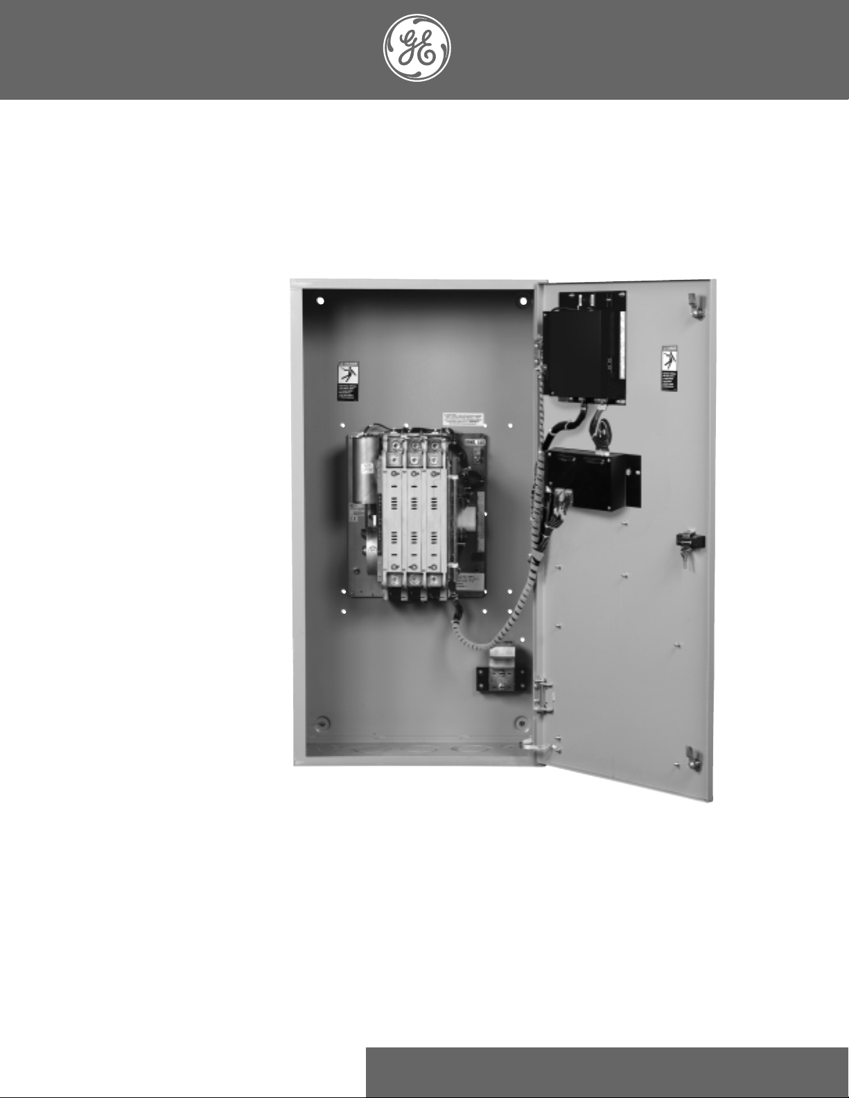
ZTG/ZTGD Series Transfer Switches
40-3000 Amps
GE Zenith Controls
Operation and Maintenance Manual
Page 2

Page
Introduction . . . . . . . . . . . . . . . . . . . . . . . . . . . . . . .12
Safety . . . . . . . . . . . . . . . . . . . . . . . . . . . . . . . . . . . . .13
Equipment Inspection and Storage . . . . . . . . .13
Final Equipment Inspection . . . . . . . . . . . . . . .13
Installation . . . . . . . . . . . . . . . . . . . . . . . . . . . . . . . . .13
Mounting . . . . . . . . . . . . . . . . . . . . . . . . . . . . . .13
Power Connections . . . . . . . . . . . . . . . . . . . . . .14
Engine Start Control Connections . . . . . . . .14-6
Initial Energization . . . . . . . . . . . . . . . . . . . .16-7
MX150 Microprocessor Controller . . . . . . . . . . . . .18
Overview . . . . . . . . . . . . . . . . . . . . . . . . . . . . . . .18
LCD & Keypad . . . . . . . . . . . . . . . . . . . . . . . . . .19
User Setting for Voltage & Frequency . . . . . .110
Standard Features, MSTDG Option Pkg. . .10-11
Standard Features, MEXEG Option Pkg. . . . .12
Optional Accessories . . . . . . . . . . . . . . . . . . . . .13
How to Set the System Clock . . . . . . . . . . . . . .14
CDT One Event Timer Exerciser . . . . . . . .14-15
CDP Clock Exerciser . . . . . . . . . . . . . . . . . . . . .16
User Setup - CFG Menu . . . . . . . . . . . . . . . . . .17
User Setup - SET Menu . . . . . . . . . . . . . . . . . .18
User Setup - System Info . . . . . . . . . . . . . . . . . .19
Testing . . . . . . . . . . . . . . . . . . . . . . . . . . . . . . . . . . .120
Standard Transition . . . . . . . . . . . . . . . . . . . . .120
Delayed Transition . . . . . . . . . . . . . . . . . . . . . .20
Page
Sequence of Operation . . . . . . . . . . . . . . . . . . . . . .21
Standard Transition . . . . . . . . . . . . . . . . . . . . .121
Delayed Transition . . . . . . . . . . . . . . . . . . . . . .21
Controls Power Supply (CPS) . . . . . . . . . . . . . . . . .22
Schematics, Standard & Delay . . . . . . . . . . . .123
Troubleshooting & Diagnostics . . . . . . . . . . . . . . . .24
Maintenance and Testing . . . . . . . . . . . . . . . . . . . . .25
Inspection and Cleaning . . . . . . . . . . . . . . . . .25
Servicing . . . . . . . . . . . . . . . . . . . . . . . . . . . . . .125
Testing . . . . . . . . . . . . . . . . . . . . . . . . . . . . . . .125
Power Panel & Replacement Parts . . . . . . . . . . . . .26
Standard Transition . . . . . . . . . . . . . . . . . . . . . .26
40-260 Amps . . . . . . . . . . . . . . . . . . . . . . . . . . .26
400-600 Amps . . . . . . . . . . . . . . . . . . . . . . . . . .27
800-1200 Amps . . . . . . . . . . . . . . . . . . . . . . . . .28
1600-3000 Amps . . . . . . . . . . . . . . . . . . . . . . . .29
Delayed Transition . . . . . . . . . . . . . . . . . . . . . .30
40-600 Amps . . . . . . . . . . . . . . . . . . . . . . . . . . .30
800-1200 Amps . . . . . . . . . . . . . . . . . . . . . . . . .31
1600-3000 Amps . . . . . . . . . . . . . . . . . . . . . . . .32
Table of Contents
Introduction
GE Zenith Transfer Switches are used to provide a continuous source of power for lighting and other critical loads by automatically transferring from source 1 power to source 2 power in the event that source 1 voltage falls below preset limits.
Voltage sensing and system control is performed via a state-of-the-art microcontroller located on the cabinet door.
It is designed to give highly accurate control of the transfer switch system.
All GE Zenith transfer switches are designed for use on emergency or standby systems, and are rated for total system or
motor loads. Transfer switches are UL Listed under Standard 1008 and CSA Certified under Standard C22.2 No. 178 and
IEC Listed under Standard 947.
NOTES: A protective device such as a molded case circuit breaker or fused
disconnect switch MUST
be installed on both sources of incoming
power for circuit protection and as a disconnection device.
All references made within this manual about the term “S1” or
“Source 1” relate to a Normal Power Source. All references made
about the term “S2” or “Source 2” relate to an Emergency
or Alternative Power Source.
Authorized Service
For GE Zenith parts and service, call: (773) 299-6600
Page 3

■
GE Zenith Controls 3
■
ZTG/ZTGD Operation and Maintenance Manual (70R-1000D)
Each GE Zenith transfer switch is factory wired and
tested. A complete information package is furnished
with each switch which includes:
a. Sequence of operation.
b. Description and operation of
all accessories supplied.
c. Power panel connection diagram
and schematic.
d. Description and identification of
all customer field connections.
Installation of GE Zenith transfer switches includes:
a. Mounting the transfer switch cabinet.
b. Connection of Source 1, Source 2,
and Load cables or bus bars.
c. Connection of external control
circuits as required.
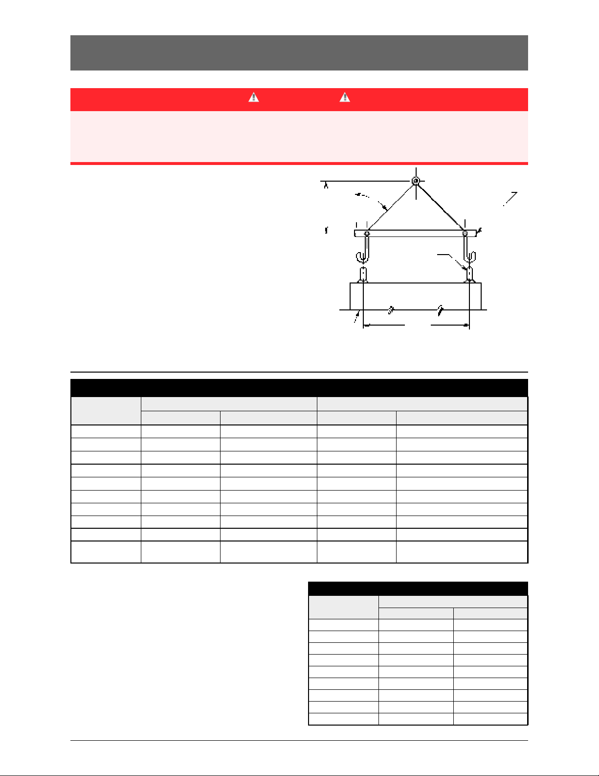
Mounting
Adequate lifting means must be used to mount the
transfer switch into place. The recommended method for
moving the transfer switch using the lifting eyes, where
supplied, and a spreader bar is illustrated in Figure 1.
Enough room should be allowed to open the cabinet
doors fully for inspection and servicing of the switch per
NEC and local codes.
Safety / Installation
DANGER
HAZARDOUS VOLTAGE
(Can Cause Severe Injury or Death)
Turn OFF all power before installation, adjustment, or removal of transfer switch or any of its components.
The safe operation of your switch is GE
Zenith’s focus.
The proper storage, installation, operation and maintenance will help increase the life of the switch.
Equipment Inspection
and Storage
Once you have received the transfer switch, inspect
it for any damage. This includes damage to the
enclosure, power panel, control panel and wiring
harness. If any damage is found or suspected, file a claim
as soon as possible with the carrier and notify the nearest
GE
Zenith representative.
Before installation, if it is necessary, store the transfer
switch in a clean dry place, protected from dirt and
water. Provide ample air circulation and heat, if necessary, to prevent condensation.
5% to 95%
(non-condensing)
-30°C to
+75°C
(-22°F to
+167°F)
40-400
AMP
(molded shell)
-20°C to +65°C
(-4°F to +149°F)
40-4000
AMP
(all other frame
and panel types)
-20°C to +60°C
(-4°F to +140°F)
Operating
Storage Temperature
Temperature (Ambient): Humidity
CAUTION
Due to hazardous voltage and current, GE Zenith rec-
ommends that a
GE Zenith Certified technician or a
qualified electrician must perform the
installation and maintenance of the switch.
Final Equipment Inspection
Prior to energizing the transfer switch:
1. Remove any debris incurred, with a vacuum, due
to shipment or installation.
WARNING
Do not use a blower since debris may
become lodged in the electrical and
mechanical components and cause damage.
2. Verify that all cabled connections are
correct and that phase rotation of both sources
match.
3. Check engine start connections.
4. Verify the correct connection of all
control wires.
5. Check settings of all timers and adjust
as necessary.
6. Adjust any optional accessories as required.
7. Check the lug torque values of the power
connections.
NOTE
: Lug torque values are specified
in table 2 on pg.4.
8. Make sure that all covers and barriers are
installed and properly fastened.
NOTE
: Power panels ship from GE Zenith
in Source 1 Position.
CAUTION
Before drilling conduit entry holes or any
accessory mounting holes, cover and protect
the switch and control panel to prevent dirt
and metal fragments from entering the
mechanical and electrical components.
Failure to do so may result in
damage and malfunction of the switch.
Page 4
■
4 GE Zenith Controls
■
ZTG/ZTGD Operation and Maintenance Manual (70R-1000D)
Table 2
Tightening Torque for Lugs
Socket Size
Across Flats
Torque
Lb. - In.
Lb. - Ft.
45
1/8
4
100
5/32
8
120
3/16
10
150
7/32
12
200
1/4
17
275
5/16
23
375
3/8
31
500
1/2
42
600
9/16
50
Installation (cont’d)
D
CABINET
LIFTING EYES
SPREADER BAR
H
45°
Figure 1
Power Connections
GE Zenith transfer switches are supplied with UL listed
solderless screw type terminals as standard for the
Source 1, Source 2 and Load power connections.
Table 1 lists the number and sizes of cable lugs supplied
as standard for each switch amp rating.
Connect the Source 1, Source 2, and Load conductors
to the clearly marked terminals on the transfer switch.
Remove surface oxides from cables by cleaning with a
wire brush. Verify that all connections are correct before
tightening the lugs. All cable lug connections must be
tightened to the proper torque values as shown in
Table 2.
NOTE
: Do not run cables or wiring behind
front-connected transfer switches.
DANGER
HAZARDOUS VOLTAGE
(Can Cause Severe Injury or Death)
Turn OFF all power before installation, adjustment, or removal of transfer switch or any of its components.
Table 1
Power Connections: Screw Type Terminals for External Power Connections
Switch Size
(Amps)
40
80
100
150
200, 225
400
600
800, 1000, 1200
Source 1, Source 2 & Load Terminals
1 #8 to 3/0 AWG
Cable Per Pole Range of Wire Sizes
1 #8 to 3/0 AWG
1 #8 to 3/0 AWG
1 #8 to 3/0 AWG
1 #6 AWG to 250 MCM
1 #4 AWG to 600 MCM
2 #2 AWG to 600 MCM
4 #2 AWG to 600 MCM
Neutral Bar (When Required)
3 #14 to 1/0 AWG
No. of Cables Range of Wire Sizes
3 #14 to 1/0 AWG
3 #14 to 1/0 AWG
3 #6 AWG to 350 MCM
3 #6 AWG to 350 MCM
4 #4 AWG to 600 MCM
260
1 #6 AWG to 350 MCM 3 #6 AWG to 350 MCM
8 #4 AWG to 600 MCM
12 #4 AWG to 600 MCM
1600, 2000
2600, 3000
8 #2 AWG to 600 MCM
24
#4 AWG to 600 MCM
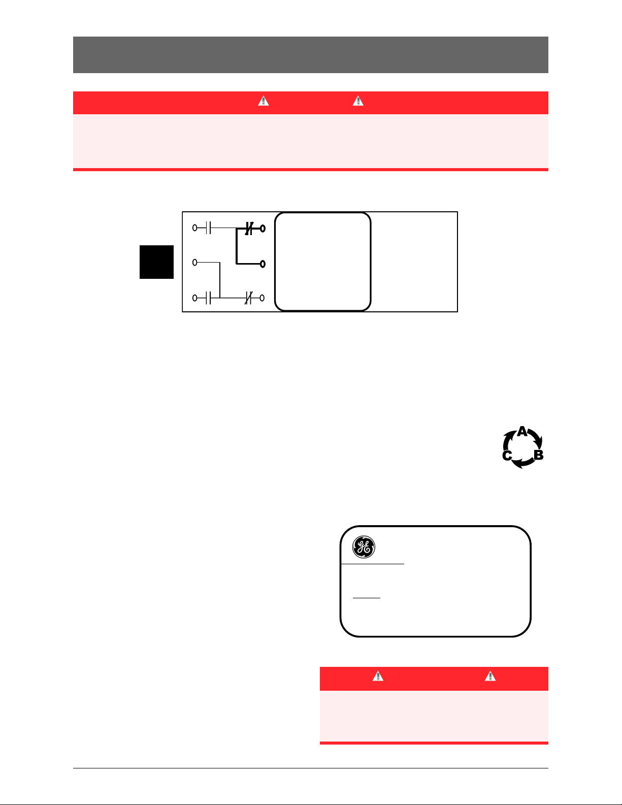
Engine Start
Control Connections
Engine-start control wires connect to control terminals
beside the MX150. Engine start terminals are indicated by
a schematic symbol (the symbol indicates the contact
state for a de-energized normal source). Figure 3 shows
the engine-start contacts.
Make all other necessary control connections to the control panel terminal blocks per the schematics supplied
with the ATS.
NOTE: All control wires (18-12 AWG) must be
torqued to 19 in/lbs.
NOTE
: When lifting the switch using a spreader bar,
height H must be equal to half of distance D.
Page 5
■
GE Zenith Controls 5
■
ZTG/ZTGD Operation and Maintenance Manual (70R-1000D)
Installation (cont’d)
A complete information package is furnished with
each transfer switch including a complete connection
diagram and schematic which details all necessary
control circuit field connections.
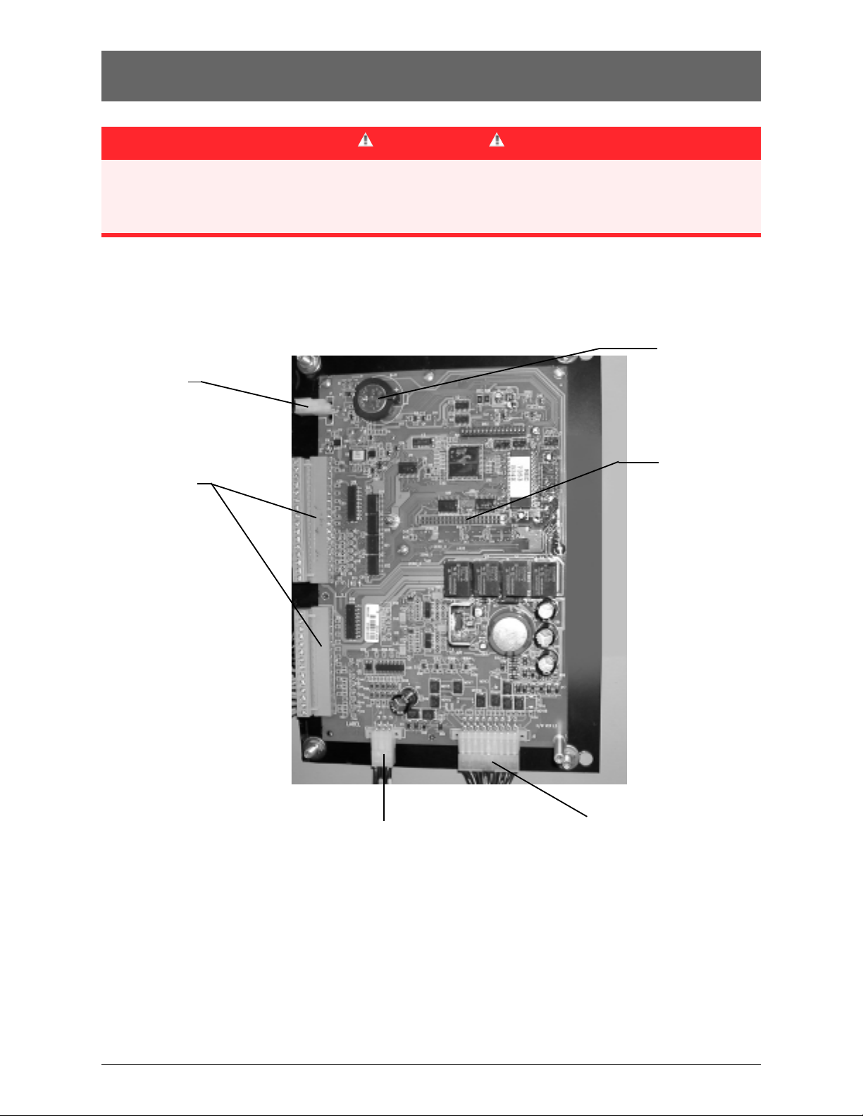
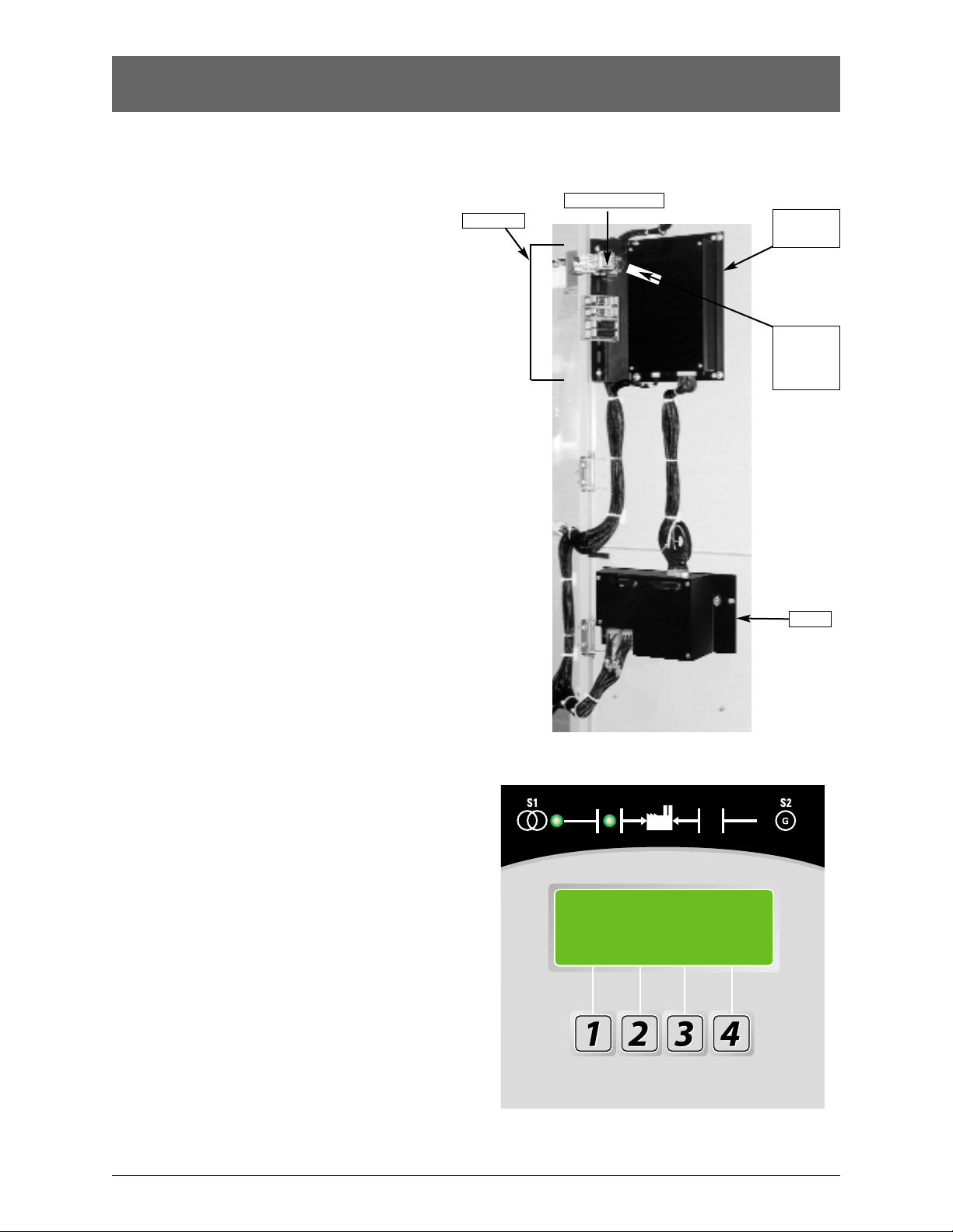
The engine start control wires connect to the
engine start relay terminals located to the left
of the microprocessor. Figure 2 shows the location
of these terminals.
DANGER
HAZARDOUS VOLTAGE
(Can Cause Severe Injury or Death)
Turn OFF all power before installation, adjustment, or removal of transfer switch or any of its components.
To R/T Box
To Power
Panel
Input/Output
Connectors
to I/O Modules
Engine Start
Connections
Clock Program
Backup Battery
Remove protective
strip to enable clock
functions
Network Connector
Control Connections
The terminals are clearly identified by a label on the
microcontroller backplate. In the case of manual transfer switches, or in other applications not requiring the
microprocessor, clearly marked terminal blocks are
provided in the upper left corner of the control panel
for the engine start control wires.
Figure 2
Page 6
■
6 GE Zenith Controls
■
ZTG/ZTGD Operation and Maintenance Manual (70R-1000D)
Installation (cont’d)
Engine Start
Control Connections
The engine-start terminals are clearly identified by a
label on the microcontroller backplate. In the case of
manual transfer switches, or in other applications not
requiring the microprocessor, clearly marked terminal
blocks are provided in the upper left corner of the control panel for the engine start control wires.
Terminals for field connections to the A3 Source 2
auxiliary contacts and the A4 Source 1 auxiliary contacts
are also provided. These terminals are clearly marked
and appear on the side of the power panel. On 400
amp metal frame units these terminals appear on the
bracket above the operator handle.
Initial Energization
Before proceeding, refer to the information package
supplied with the ATS and read and understand the
information on all accessories provided.
1. Unlock the enclosure.
2. Open the enclosure.
3. Verify the correct system voltage.
NOTE: The equipment rating nameplate on
the transfer switch lists the voltage.
See Figure 4.
4. Close Source 1 circuit. breaker.
NOTE:The controller will illuminate Source 1
Available LED if proper voltage
is sensed.
5. Verify the phase to phase voltages at the Normal
line terminals.
6. Close the Source 2 circuit breaker.
7. Start the generator engine.
DANGER
HAZARDOUS VOLTAGE
(Can Cause Severe Injury or Death)
Turn OFF all power before installation, adjustment, or removal of transfer switch or any of its components.
NOTE: The controller will illuminate Source 2
Available LED when preset voltage
and frequency levels are reached.
8. Verify the phase to phase voltages at Source 1
line terminals.
9. Verify that the phase rotation of Source 1
is the same as the phase rotation of
Source 2.
10. Shut down the generator engine.
11. Place the starting control in the Automatic position.
12. Complete the visual inspection of the transfer switch.
13. Close the enclosure.
14. Lock the enclosure.
CAUTIONS
Certain accessories, per specific
schematics, can inhibit automatic transfer.
Engine Gen-Set could start when
engine control wires are attached.
Figure 4
SERIAL NUMBER:
RA
TING: VOLTS -
AMPS -
SYSTEM VOLTS:
MODEL NUMBER:
HZ -
PHASE -
GE Zenith Controls
E
Figure 3
4
5
6
1
2
(Engine Start)
3
P Relay
Contact rating is
10 Ampere at 120VAC
or 28VDC Gold plated
Page 7
■
GE Zenith Controls 7
■
ZTG/ZTGD Operation and Maintenance Manual (70R-1000D)
Installation (cont’d)
5. Close the External (up-stream) Source 2 line
circuit breaker.
6. Start the engine generator in
MANUAL mode.
NOTE: When the voltage and frequency
reach preset values, the Source 2
Available
LED will illuminate.
7. Verify the phase to phase voltages at Source 2
line terminals.
8. Verify that the phase rotation of
Source 2 is the same as the phase
rotation of Source 1.
9. Shut down the generator's engine.
(Place in Automatic Mode.)
NOTE: Source 2 Available LED
will turn off.
NOTE: The engine generator will continue
to run for the duration of Source 2
Stop Delay Timer.
10. Place the disconnect switch to ENABLE.
11. Complete the visual inspection of the
transfer switch.
12. Close the enclosure.
13. Lock the enclosure.
MX150
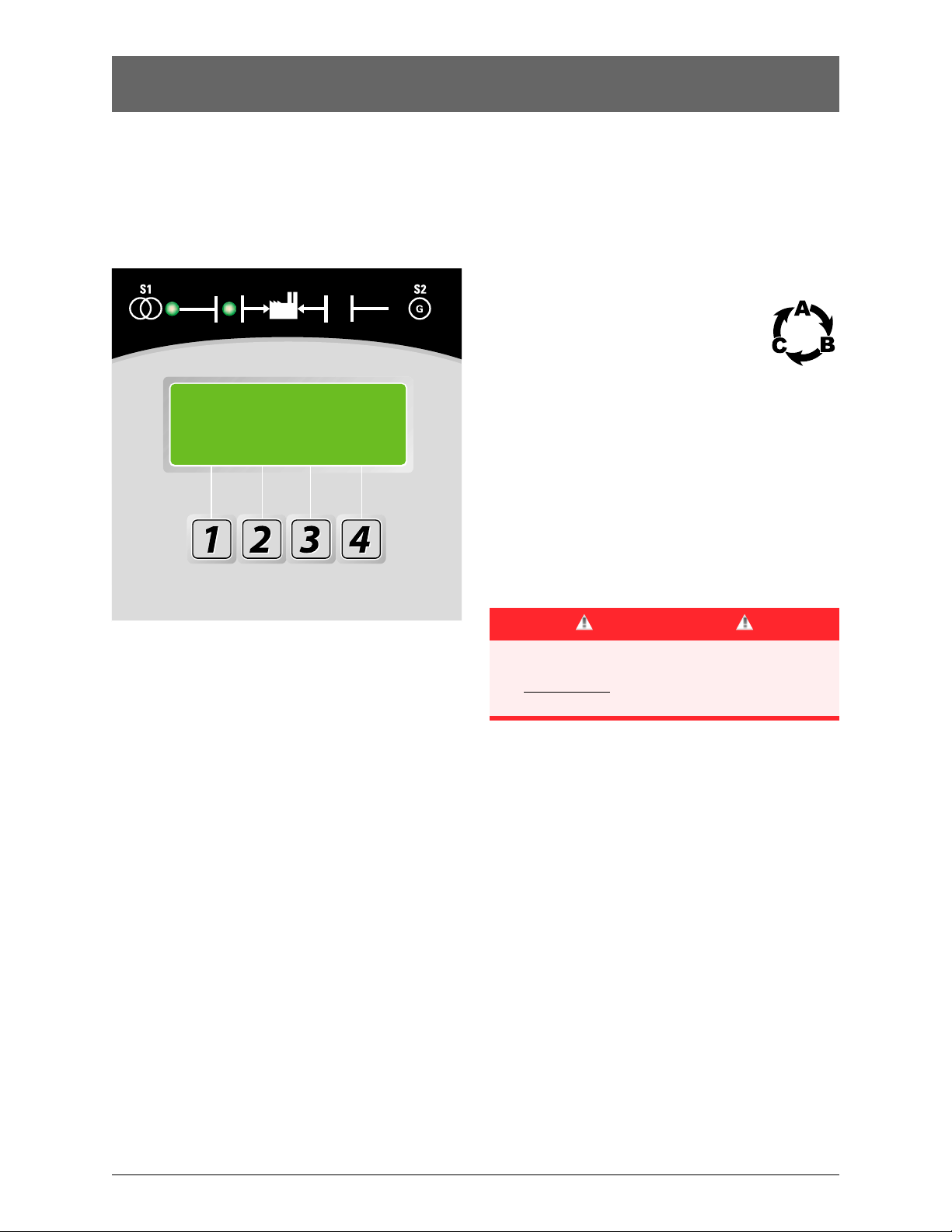
Figure 5 – LCD and keypad
Initial Energization (cont’d)
After all options and accessories are checked and verified, follow these steps to set up the ATS. Refer to MX150
display Figure 5. The annunciation LEDs illuminate to
indicate (1) source availability, (2) ATS position, and (3)
MX150 control function (timing).
1. Unlock the enclosure.
2. Open the enclosure.
3. Place the Disconnect Switch in the Inhibit.
NOTE
: This step is only performed if the
“DS” Option was purchased.
4. Close the external (up-stream) Source 1
circuit breaker.
NOTES: Source 1 Available and Source 1
Position LED’s will illuminate.
If Source 1 Available
LED does not
illuminate, verify that Source 1 Voltage
is above the preset restore value.
The Gen-Set will start and run while
Source 2 stop Delay Timer is timing.
WARNING
When performing a hi-pot or
dielectric test on the power section,
DISCONNECT the control panel plugs from
the microprocessor to avoid potential damage.
S1 OK
21:56
MON 23 APR 2002
MORE TEST
Page 8
■
8 GE Zenith Controls
■
ZTG/ZTGD Operation and Maintenance Manual (70R-1000D)
MX150 Microprocessor Controller
MX150 Controller
Consists of two major assemblies:
I. The Microprocessor contains the following:
A. MX150 Board - Customer Input and Output
(I/O) for system interface. Located on the left
hand side of the back of the unit (see figure 6)
1. I/O accessories that can be found here are:
a. Engine start relay P output
b. Pre-Signal to transfer T3, W3 and
UMD output (optional)
c. Transfer Inhibit Q3 and Q7 input
(optional)
d. Remote test Q2 input (optional)
e. Network interface ZNET
input/output (optional)
B. LCD and Keypad located on the exterior
of the door (see figure 7)
1. User accessibility to the following:
a. LED indication of source
availability
b. LED indication of transfer
switch position
c. LCD screen indicates:
(1) timer count down (numeric)
(2) event reporting (text)
d. Keypad provides user interface to:
[in conjunction with LCD screen]
(1) Setting sensors and timers
(2) Configuring logic accessories
II. The Controls Power Supply (CPS)
Contains transformers which drop line voltage to
control level for controller input and SCR inputs
(see figure 6).
Figure 7
Figure 6
I/O Interface
CPS
Engine Start Relay P
Battery Strip
and
Access
Code Label
MX150
Board
MX150
S1 OK
21:56
MON 23 APR 2002
MORE TEST
Page 9
■
GE Zenith Controls 9
■
ZTG/ZTGD Operation and Maintenance Manual (70R-1000D)
MX150 Microprocessor Controller (cont’d)
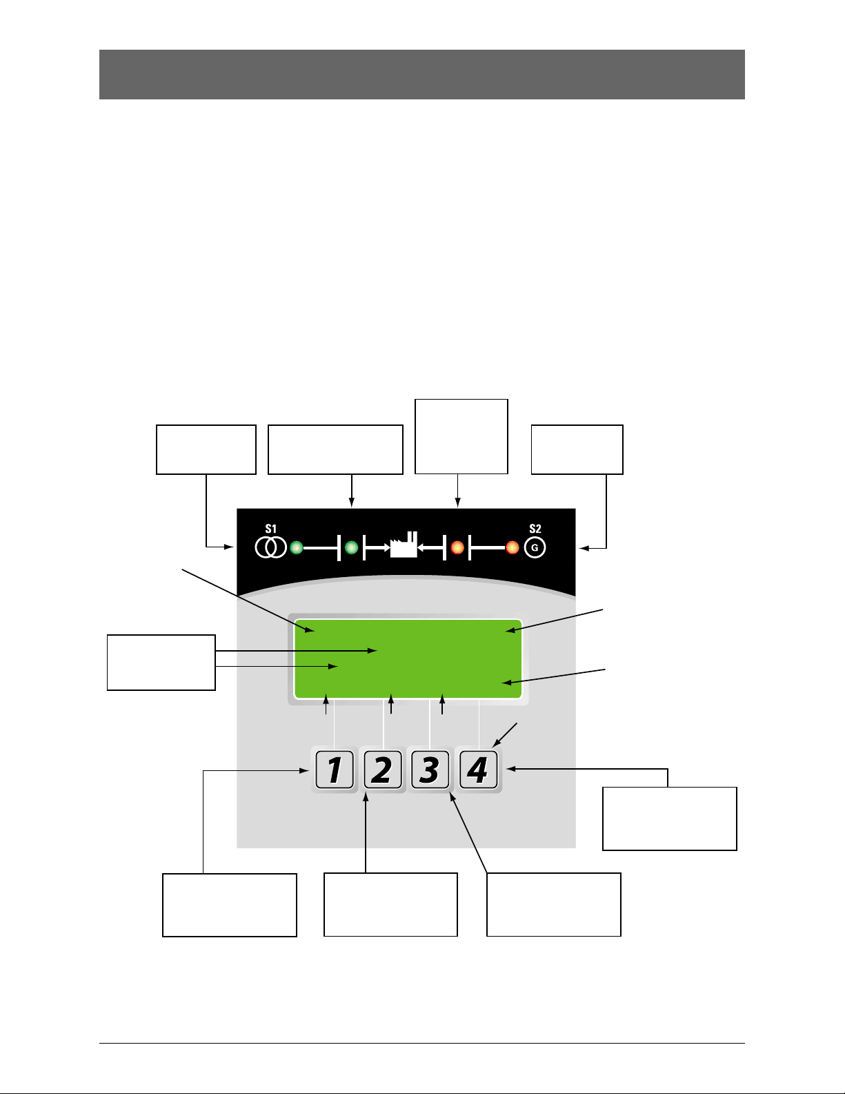
Figure 8
LCD & Keypad
These options are accessible through the LCD and
keypad (see figure below). To become familiar with the
options loaded into a particular unit, scrolling through
the SET and CFG menu will show the descriptions of
the options (see pages 17). These menus are the very
same menus that are used to access the setting and/or
configuration of these options. The SET (setting) menu
is primarily used to show or change, time and voltage
settings. The CFG menu is primarily used to turn an
option on or off. When scrolling through these menus,
no changes can be made without entry of the access code.
The factory set six-digit access code is located on a white
label on the back of the unit (see figure 9 pgs. 17-19).
The MX150 has many logic options. Each controller is
downloaded with options at the time of manufacture.
The collection of options that any one controller has is
specified at the time of order placement. The following
pages include all the options that can reside in the
controller. Not all units include all options.
Source 1 LED (Green)
indicates Source 1 is
acceptable for use
Source 1 Position LED (Green)
indicates Power Panel (ATS)
is closed to Source 1 position
Source 2 Position
LED (Red) indicates
Power Panel (ATS)
is closed to
Source 2 position
Source 2 (Red)
indicates Source 2
is acceptable for use
LCD Screen
Current Time,
Day and
Date of Display
#1 or the word
on the LCD above the key.
The word above the key
changes depending on which
screen is being displayed.
S1 OK
01: 50
FRI 31 MAY 2003
MORE CFG TEST SET
MORE Menu
CFG Menu
TEST Menu
MX150
#2 or the word
on the LCD above the key.
The word above the key
changes depending on which
screen is being displayed.
Exercise Event
"Impending"
* E *
SET Menu
Keypad
#4 or the word
on the LCD above the key.
The word above the key
changes depending on which
screen is being displayed.
#3 or the word
on the LCD above the key.
The word above the key
changes depending on which
screen is being displayed.
Page 10

■
10 GE Zenith Controls
■
ZTG/ZTGD Operation and Maintenance Manual (70R-1000D)
User Setting for Voltage & Frequency
Standard Features, MSTDG Option Pkg.
Source 1
Voltage "Restore"
Factory Default: 90%
This adjustment determines the minimum acceptable
voltage required to transfer to Source 1.
Adjust via the SET menu. Range is 85% to 100% in
1% increments (see page 18).
Once satisfied, the T timer will begin timing
to transfer to Source 1.
Voltage "Fail"
Factory Default: 80%
This adjustment determines the low voltage threshold.
Adjust via the SET menu. Range is 75% to 98% in 1%
increments (see page 18).
"Fail" must be a minimum of 2 % below "Restore"
setting. Once voltage falls below threshold, P timer
begins timing to signal Source 2 Generator to start.
Source 2
Voltage "Restore"
Factory Default: 90%
This adjustment determines the minimum acceptable
voltage required to transfer to Source 2.
Adjust via the SET menu. Range is 85% to 100% in
1% increments (see page 18).
Once satisfied, the W timer will begin timing
to transfer to Source 2.
Voltage "Fail"
Factory Default: 80%
This adjustment determines the low voltage threshold.
Adjust via the SET menu. Range is 75% to 98% in 1%
increments (see page 18).
"Fail" must be a minimum of 2 % below "Restore"
setting. Once voltage falls below threshold, T timer
will be bypassed to expedite the transfer to Source 1.
Frequency "Restore"
Factory Default: 95%
This adjustment determines the minimum acceptable
frequency required to transfer to Source 2.
Adjust via the SET menu. Range is 90% to 100% in
1% increments (see page 18).
Once satisfied, the W timer will begin timing
to transfer to Source 2.
Frequency "Fail"
Factory Default: 90%
This adjustment determines the low frequency threshold.
Adjust via the SET menu. Range is 88% to 98% in
1% increments (see page 18).
"Fail" must be a minimum of 2 % below "Restore" setting.
Once satisfied, the W timer will begin timing to transfer
to Source 2.
6
Test Switch, Momentary
A3
Auxiliary Contact: Closed when the switch is in Source 2
position.
A4
Auxiliary Contact: Closed when the switch is in Source 1
position.
Calibrate
While monitoring the actual Phase to Phase voltage levels and Frequency with a calibrated test equipment, the
Phase to Phase voltage sensing and Frequency can be
adjusted accordingly. Calibration capabilities are available
for Frequency and AB, BC, CA Phase to Phase voltage for
both Sources. Adjust via SET menu (see page 18)
CDT
Load or NO-Load. One event exerciser with adjustable
Engine exercise timer. Exercise duration can be set
between 5 and 60 minutes in 1 minute increments. Can
be configured to run every 1, 7, 14, or 28 days. Factory
Default is 20minutes. When exerciser is impending,
(*E*) appears in the upper right hand corner of LCD
screen. See page 14-15 for instructions. Configured via
CFG (see page 17). Set via SET menu (see page 18).
DS
Disconnect Switch, Auto/Inhibit.
Inhibits transfer in either direction when in inhibit.
Allows automatic operation when in Auto.
(800-4000 Amp units)
DT (Delayed Transition Only)
Time Delay from Neutral Switch position to Source 1
position. Adjustable 0-10 minutes in 1 second increments. Standard setting is 5 seconds Adjust via SET
menu (see page 18)
DW (Delayed Transition Only)
Time Delay from Neutral Switch position to Source 2
position. Adjustable 0-10 minutes in 1 second increments. Standard setting is 5 seconds.Adjust via SET
menu (see page 18)
E
Engine Start Contact
Page 11

■
GE Zenith Controls 11
■
ZTG/ZTGD Operation and Maintenance Manual (70R-1000D)
Std. Features, MSTDG Option Pkg. (cont’d)
EL/P
Event Log: Sequentially Numbered Log
of 16 events that track
date, time, reason and action taken
System Data: Total Life Transfers (N2P)
Days Powered Up
Total Transfers to S2
Total S1 Failures
Time S1 available in Hrs
Time S2 available in Hrs. (N1P)
K/P
Frequency Indication for S1 and S2
L
LNP Center-off position LCD-Indicator
Indicating LED lights:
L1 Indicates Switch in Source 2 position.
L2 Indicates Switch in Source 1 position.
L3 Indicates Source 1 available.
L4 Indicates Source 2 available.
P1
Time Delay Source 2 Start. Adjustable 0-10 seconds.
Standard setting is 3 seconds.
Adjust via SET menu (see page 18)
Q2
Peak Shave / Remote Load Test: Input for Peak Shave
or Remote Load Test. Includes automatic return to
Source 1 if Source 2 fails and Source 1 present.
R2E
Under voltage sensing of Source 2 for single-phase.
(R17 replaces R2E for Utility to Utility switches)
R50
In Phase Monitor this feature restricts Live to Live
Source Transfers to occur unless both Sources are within
7 electrical degrees or less of each other. (live Source to
live Source transfers usually occur during transfer back
to Source 1 or during Testing). R50 does not change
the operation of the Automatic Transfer Switch in a
power failure mode. After all timer functions have
elapsed, the CHECKING FOR SOURCE SYNCHRO-
NISM will be displayed as well as the direction of
transfer (S1-S2 for example denotes transfer from
Source 1 to Source2). When synchronism is accomplished,
transfer will take place.
Notes: - If S2 Frequency is less than S1 Frequency,
display will show a series of (- - - - -…..) symbols.
- If S2 Frequency is greater than S1 Frequency,
display will show a series of (+++++…..) symbols.
- Each (-) or (+) symbol represents 10 electrical
degrees out of phase. A maximum of 18 symbols
(180 electrical degrees) can be monitored.
- The number of (-) or (+) symbols decrease
as the two sources approach synchronism
and increase as the two sources drift out
of synchronism.
- If S1 and S2 Frequencies are identical, the
display will show a series of alternating
- - - -
symbols (++++…) which also indicate the
approximate out of phase degrees
In the event that the Sources do not come within 7
electrical degrees of each other within 60 seconds, the
unit will display the message: SYNCH CHECKING and
will allow the user to BYPASS. If the BYPASS button is
pressed, the unit will display the message: WARNING
MAY CAUSE DAMAGE TO THE LOAD. Pressing XFR
will actually bypass the R50. Since R50 is a passive device,
the length of time it takes to reach Synchronism is dependent on the frequency difference between the two
Sources. Source 1 is usually a Utility and the frequency
is not within the control of the consumer. Source 2
needs to be adjusted to create an adequate difference
in order for the transfer to happen a timely fashion.
Note: For optimum performance, Source 2
Generator should be adjusted a Maximum of
2 Hertz above or below the Utility frequency,
minimum of 0.1 Hertz. (58 to 59.9) or
(60.1 to 62) Hertz. Adjustment of Generator
to 60Hertz could cause lengthy transfer delay
.
R50 Feature can be turned ON or OFF via CFG Menu
(see page 17). Factory Default if OFF.
S13
Transfer Commit. Configured via CFG menu.
(see page 17) When this Feature is set to OFF:
The transfer Switch is not committed to transfer unless
the outage duration is longer than the timers that
precede the transfer to Source 2 position. This assumes
that the outage will be an isolated event. When this
Feature is set to ON: The transfer Switch is committed
to transfer to Source 2 position once the W timer has
begun timing, even if Source 1 power returns before
the transfer to Source 2. This is to ensure that the
transfer takes place, because one outage may be
followed by another.
T
Time Delay (S1) Source 1 Stable Timer. To delay transfer to Source 1 (immediate retransfer on Source 2 failure). Adjustable 0-60 minutes in 1 second increments.
Standard setting is 30 minutes. Adjust via SET menu
(see page 18)
U
(S2) Source 2 Stop Delay Timer. Allows Engine to run
unloaded after switch retransfer to Source 1. Adjustable
0-60 minutes in 1 second increments. Standard setting is
5 minutes. Adjust via SET menu (see page 18)
W
Time Delay (S2) Source 2 Stable Timer. To delay transfer to Source 2. Adjustable 0-5 minutes in 1 second
increments. Standard setting is 1 second. Adjust via SET
menu (see page 18)
YEN
Bypass Timers Key utilizing Keypad. When applicable,
the system prompts the user to press a button to bypass
(T) or (W) Timers should the user so desires.
Page 12

■
12 GE Zenith Controls
■
ZTG/ZTGD Operation and Maintenance Manual (70R-1000D)
In addition to the features listed under the
MSTDG Option Package, this enhanced package
includes the following features:
A3
Additional Auxiliary contact: closed when switch is in
Source 2 position.
A4
Additional Auxiliary contact: Closed when the transfer
switch is in Source 1 position.
CDP (replaces CDT)
Clock Exerciser Load/ No Load: Allows the Generator
to start and run unloaded or to simulate a power
failure, start Generator and run under load.
Can be configured by end user for 1, 7, 14,
28, 365 day cycle.
Standard Features, MEXEG Option Pkg.
VI
Voltage Imbalance (Three Phase)
For a three phase source, this feature monitors phase
voltage ratios based on a selected range within a
selected time window. Should any phase fall below the
selected lower window limit or exceed the selected
higher window limit within the selected time frame,
the controller initiates transfer to the other source.
Range: 5% to 20% of Nominal voltage,
10 to 30 seconds window, user adjustable.
Resolution: 1% Increments
Minimum Differential: 2% between “Fail”
and “Restore” settings.
Factory default: 10% “Fail”, 8% “Restore, 30 Seconds.
See CFG Menu page 17 to configure ON or OFF.
See SET Menu page 18 to set Percentage and time
windows
Page 13

■
GE Zenith Controls 13
■
ZTG/ZTGD Operation and Maintenance Manual (70R-1000D)
6A
Test Switch, Maintained / Momentary
6AP
Test Switch, Maintained / Momentary, utilizing Keypad
A1
Auxiliary Contact, operates on Source 1 line failure.
A1E
Auxiliary Contact, operates on Source 2 line failure.
A3
Auxiliary Contacts: Closed when the transfer switch
is in Source 2 position.
A4
Auxiliary Contacts: Closed when the transfer switch
is in Source 1 position.
A62
Sequential Universal Motor Load Disconnect Circuit.
Normally closed Auxiliary contacts for Motor Loads.
Open 0-60 seconds prior to transfer, after transfer, or
both in either direction then re-close in timed sequence
after transfer. Factory default: 20 seconds
CTAP
Alarm Panel on transfer to Source 2 with Silence button.
DS
Disconnect Switch, Auto/Inhibit.
Inhibits transfer in either direction when in inhibit.
Allows automatic operation when in Auto.
(40-600 Amp units)
HT
Heater and Thermostat.
Manual
Manual Transfer Switch transfers in either direction
by depressing designated pushbuttons.
M80
Digital Power Meter with Display: Amps, Volts, and
Frequency.
M82
Digital Meter w/Display of Amps, Watts, Volts,
Frequency, KVA, KVAR, PF, etc.
M83A
Digital Meter w/Diplay of Amps, Watts, Volts,
Frequency, KVA, KVAR, PF, etc. Plus THD capability
w/Modbus.
T3/W3
Elevator Pre-Signal Auxiliary Contacts: Open 0-60
seconds prior to transfer to either direction,
re-closes after transfer. Factory default: 20 seconds
UMD
Universal Motor Load Disconnect Circuit: Auxiliary
Contact opens 0-5 minutes prior to transfer in either
direction, re-closes after transfer. Can be configured
by end user for Pre-transfer, Post-transfer, or both.
Factory default: 15 seconds
VI
Voltage Imbalance (Three Phase)
For a three phase source, this feature monitors phase
voltage ratios based on a selected range within a
selected time window. Should any phase fall below the
selected lower window limit or exceed the selected
higher window limit within the selected time frame,
the controller initiates transfer to the other source.
Range: 5% to 20% of Nominal voltage,
10 to 30 seconds window, user adjustable.
Resolution: 1% Increments
Minimum Differential: 2% between “Fail”
and “Restore” settings.
Factory default: 10% “Fail”, 8% “Restore, 30 Seconds.
See CFG Menu page 17 to configure ON or OFF.
See SET Menu page 18 to set Percentage and time
windows
ZNET
Network Communications Interface Card
Optional Accessories
Page 14

■
14 GE Zenith Controls
■
ZTG/ZTGD Operation and Maintenance Manual (70R-1000D)
How to Set the System Clock
How to Set the System Clock
Set System Clock, time and date
· If the clock is not set, the display will show
SET SYSTEM CLOCK on the second line
of the S1 OK screen.
· The S1 OK screen will show time (hours and
minutes) on the second line if the system clock
has been set. (Date on third line)
Setting the System Clock
(Start from S1 OK screen)
1. Remove battery protective white plastic strip
near P relay. *
2. Press MORE then press SET.
3. Press MORE and scroll to SET SYSTEM CLOCK
using the MORE key.
4. Press SEL.
5. ENTER ACCESS CODE located on the white label
on the back of the controller.
6. Press SEL.
7. Use the up and down keys to change the hour value.
8. Press SAVE (this will enter this value and move
cursor to minutes).
9. Use the up and down keys to change the minutes.
10. Press SAVE (this will enter this value and move
cursor to month).
11. Use the up and down key up to change the month.
12. Press SAVE (This will enter this value and complete
the clock setting).
13. Use the up and down keys to change the date.
14. Press SAVE (this will enter this value and move
cursor to year).
15. Use the up and down keys to change year.
16. Press SAVE (this will enter this value and
compete the clock setting).
17. To edit settings, press SEL and repeat steps 6-16.
18. If the setting is satisfactory, press MORE
(unit then returns to the SET menu then
press BACK, then ESC.)
* Replacement battery part #K-4100
Battery will last 5 years and provides power to retain clock
function only (Controller functions without battery).
Load / No-Load
One event Exerciser with adjustable Timer. Exercise
duration can be set between 5 and 60 minutes in
1 minute increments. Can be configured to run every
1,7,14, or 28 days. Factory default is 20 minutes.
How to CONFIGURE (CFG) and Set (SET)
the Timer Exerciser
1. Beginning from the S1 OK screen,
press MORE then CFG.
2. Press MORE to scroll to CONFIG TIMER
EXERCISER screen.
3. The third line of the CONFG TIMER EXERCISER
will show either DAILY, WEEKLY, 14 DAY, 28 DAY,
or OFF.
4. If the third line of the CONFG TIMER EXERCISER
shows DAILY, WEEKLY, 14 DAY, or 28 DAY as
desired, then proceed to step 10.
5. If the third line of the CONFG TIMER EXERCISER
shows OFF or if another timer selection is desired,
continue.
6. Press SEL.
7. Enter ACCESS code located on white label
on the back of the controller.
8. Press UP or DOWN to select DAILY, WEEKLY,
14 DAY, or 28 DAY as desired.
9. Press SAVE.
10. Press MORE to scroll to CONFG TIMER
EXERCISER (XFR) or (NO XFR).
11. Press Up or Down to select XFR (Load Transfer)
or NO XFR (No Load Transfer).
12. Press SAVE.
13. Press MORE repeatedly to BACK then S1 OK screen.
Set (SET) the Exerciser:
14. Beginning from the S1 OK screen,
press MORE then SET.
15. Press MORE repeatedly until
EXER S2 RUN TIME screen.
16. Press SEL
17. Enter ACCESS code located on white label
on the back of the controller.
18. Press SEL
19. Cursor is indicated as a line under character to
be changed. Change values with up and down keys.
20. Press SAVE when complete.
21. Press MORE repeatedly until SET USER SETUP
then press BACK then ESC to the S1 OK screen.
CDT One Event Timer Exerciser
Page 15

■
GE Zenith Controls 15
■
ZTG/ZTGD Operation and Maintenance Manual (70R-1000D)
CDT One Event Timer Exerciser (cont’d)
How to Initiate CDT Exerciser and to start an
exercise cycle every 1, 7, 14, or 28 days
From S1 screen
1) Press TEST
2) Press MORE
3) Press START TEST TIMER (to initiate Test).
• If the CDT Exerciser is Factory configured for a
Load Exerciser, the Controller will immediately start
a load exercise. The controller will start the
generator, transfer the load to Source 2 and remain
in Source 2 for the duration set for EXER S2 RUN
TIME in the SET menu. The controller will
retransfer the load back to Source 1 after the S1
stable timer has timed out and run the generator
unloaded for the duration of the S2 stop delay timer
(Engine Cool Down Timer).
• If the CDT Exerciser is Factory configured for a
No-Load Exerciser, the Controller will immediately
start a No-load exercise. The controller will start the
generator and run it unloaded for the duration of
the S2 stop delay timer (Engine Cool Down Timer).
Exercise will be repeated at the same time as initiated
on every 1, 7, 14, or 28 days according to the selection
made in the Configure CFG menu.
How to Bypass (Cancel) an exercise during
an exercise cycle
1) Press BPASS
2) Allow the controller to complete the Engine
cool down cycle
If the CDT Exerciser is Factory configured for a
No-Load Exerciser Or allow the controller to complete
retransfer to Source 1 If the CDT Exerciser is Factory
configured for a Load Exerciser
How to Bypass the next exercise event and Keep
the rest of scheduled events unchanged
1) Press Test
2) Press MORE
3) Press BYPASS EXER
To re-institute the next exercise event back,
press CANCL BPASS
How to initiate a new exercise start time
1) Press TEST
2) Press MORE
3) Press EXER CANCL
4) Press START TIMER TEST
How to check the next exercise event
1) From S1 OK screen, press MORE three times.
2) The unit will display the PLANT EXERCISER NEXT
event in DAYS, HOURS, and MINUTES
3) Press ESC to S1 OK Screen.
Notes:
- *E* appears in the upper right hand corner
of LCD screen when exercise is impending.
- For Load Exerciser, actual exercise period
(ATS in S2 position)= CDT (Exerciser)
timing period +T (S1 stable Timer) timing period.
Page 16

■
16 GE Zenith Controls
■
ZTG/ZTGD Operation and Maintenance Manual (70R-1000D)
CDP Clock Exerciser
Load / No-Load Clock Exerciser
Allows the Generator to start and run unloaded or to
simulate a power failure, start Generator and run under
load. Can be configured by the end user for 1, 7, 14, 28,
or 365 day cycles.
• A total of 7 independent No Load exercise periods
(up to 10 hours each) can be programmed for each
of the daily, weekly, 14-day, and 28-day exercisers.
• A total of 12 independent No Load exercise periods
(up to 10 hours) can be programmed for the
365-day Exerciser.
How to Configure (CFG) the Exerciser
1. Beginning from the S1 OK screen, press MORE
then CFG.
2. Press MORE to scroll to CONFIG CLOCK
EXERCISER screen.
3. The third line of the CONFG CLOCK EXERCISER
will show either DAILY, WEEKLY, 14 DAY, 28 DAY,
365 DAY or OFF.
4. If the third line of the CONFG CLOCK EXERCISER
shows DAILY, WEEKLY, 14 DAY, 28 DAY, or 365 DAY
as desired, press MORE repeatedly to BACK.
Press ESC then proceed to the SET menu to
set the EXERCISER.
5. If the third line of the CONFG CLOCK EXERCISER
shows OFF, continue.
6. Press SEL.
7. Enter ACCESS code located on white label on
the back of the controller.
8. Press UP or DOWN to select DAILY, WEEKLY,
14 DAY, 28 DAY, or 365 DAY as desired.
9. Press SAVE.
10. Press MORE repeatedly to BACK then ESC
to S1 OK screen.
How to set (SET) the DAILY Exerciser
1. Beginning from the S1 OK screen, press MORE
then SET.
2. Press MORE repeatedly until SET EXERCISER
screen.
3. Press SEL.
4. Enter ACCESS code located on white label
on the back of the controller.
5. Press SEL
6. Cursor is indicated as a line under character to
be changed. Change values with up and down keys.
Press SAVE after each entry to save value and to
move to the next value to be changed.
7. Press BACK when complete.
8. Press MORE repeatedly until SET USER SETUP.
Press BACK then ESC to the S1 OK screen.
How to Bypass (Cancel) an exercise during
an exercise cycle
1) Press BPASS
2) Allow the controller to complete the Engine
cool down cycle.
If the CD Exerciser is configured or Set for a No-Load
Exercise. Or allow the controller to complete retransfer
to Source 1. If the CD Exerciser is configured for a
Load Exerciser
How to Bypass the next exercise event and Keep
the rest of scheduled events unchanged
1) Press TEST
2) Press MORE
3) Press BYPASS EXER
To re-institute the next exercise event back,
press CANCL BPASS
How to check the next exercise event
1) From S1 OK screen, press MORE three times.
2) The unit will display the PLANT EXERCISER NEXT
event in DAYS, HOURS, and MINUTES
3) Press ESC to S1 OK Screen.
Notes:
• In the S1 OK screen, an (*E*) appears in the upper
right hand corner of LCD screen when exercise
is impending.
• For Load Exerciser, actual exercise period
(ATS in S2 position)= CDT (Exerciser)
timing period +T (S1 Stable Timer) timing period.
• A value greater than zero must be entered in the
Exerciser duration field to be accepted as a valid
exercise period.
• The Exercise cycle will be repeated on a regular
basis as programmed and initiated in the SET menu
depending on what Exerciser was configured
(selected) in the CFG menu.
Indicates # of
Exercise Periods
Indicates type of Exerciser
DAILY, WEEKLY, 14-DAY,
28-DAY or 365-DAY
Indicates Exerciser start:
Time for DAILY Exerciser
Time & Day for WEEKLY Exerciser
Time, Date & Month for 14-DAY,
28-DAY and 365-DAY Exerciser
(24 Hour System)
EXERCISER
00:00
BACK ^ v SAVE
To previous field
or to exit screen.
Cursor
SET
Up and Down
Use to change values.
NL#1
To save value and to
move cursor to next
field to be changed.
Load No-Load (CDP)
Exercise Indicator
Exercise duration for this
event in hours and minutes
up to 10 hours per event
Page 17

■
GE Zenith Controls 17
■
ZTG/ZTGD Operation and Maintenance Manual (70R-1000D)
MX150 User Setup - CFG Menu
Turn options ON or OFF via
keypad through the CFG menu
Enter six digit access code
(The factory assigned six-digit access code
is located on the back of the controller)
1
Engine Start Relay (De-Energized)
Network Communications
(Option)
1
2
3
4
5
6
7
8
9
10
11
12
13
14
15
16
J2
*
PROG 1
PROG 2
GRD (Input
Sink)
NIA OUT
ELEV. PRE. OUT
ALARM OUT
MOTOR DISC. OUT
INHIB.>S1
INHIB.>S2
*
1
2
3
4
5
6
7
8
9
10
11
12
13
14
J4
*
+12v (Output Source)
LN OUT
L4 OUT
L3 OUT
L2 OUT
L1 OUT
YN IN
YE IN
TSNL IN
Q2/TSL IN
S12 IN
Lithium Battery
Exerciser Battery
Replacement-K-4100 (BR2032)
Service Life-10 Years
During normal operation
User Access Code
Default-121212
PRODUCT INFORMATION
www.geindustrial.com
24-Hour Service
(773)299-6600
MX150
A2
(-)
A1
(+)
RELAY
14 11 12
Customer
Input
Voltage
COM
J2-3
N.O N.C
To
J2/J4
Inputs
WARNING
1
Controller Inputs must be relay Isolated.
2
Controller Outputs have "Limited" Source Capacity.
Use only GE Zenith-specified Output Modules.
11 14
R1
A1
(+)
12
21 24 22
A2
(-)
Output
Contacts
22
R1 Output
R1 Output
Contact Rating: 10A @ 250 VAC or 30 VDC
2
3
4
5
6
2421121411
Figure 9
S1 OK
01: 50
FRI 31 MAY 2003
MORE TEST
1 VAB = ___ 2 VAB = ___
VBC = ___
VCA = ___
MORE CFG SET ESC
CONFIG
USER SETUP
MORE BACK
Optional Accessories
Page 18

■
18 GE Zenith Controls
■
ZTG/ZTGD Operation and Maintenance Manual (70R-1000D)
MX150 User Setup - SET Menu
Change adjustable values
through the SET menu.
Enter six digit access code
(The factory assigned six-digit access code
is located on the back of the controller)
Figure 9
1
Engine Start Relay (De-Energized)
Network Communications
(Option)
1
2
3
4
5
6
7
8
9
10
11
12
13
14
15
16
J2
*
PROG 1
PROG 2
GRD (Input
Sink)
NIA OUT
ELEV. PRE. OUT
ALARM OUT
MOTOR DISC. OUT
INHIB.>S1
INHIB.>S2
*
1
2
3
4
5
6
7
8
9
10
11
12
13
14
J4
*
+12v (Output Source)
LN OUT
L4 OUT
L3 OUT
L2 OUT
L1 OUT
YN IN
YE IN
TSNL IN
Q2/TSL IN
S12 IN
Lithium Battery
Exerciser Battery
Replacement-K-4100 (BR2032)
Service Life-10 Years
During normal operation
User Access Code
Default-121212
PRODUCT INFORMATION
www.geindustrial.com
24-Hour Service
(773)299-6600
MX150
A2
(-)
A1
(+)
RELAY
14 11 12
Customer
Input
Voltage
COM
J2-3
N.O N.C
To
J2/J4
Inputs
WARNING
1
Controller Inputs must be relay Isolated.
2
Controller Outputs have "Limited" Source Capacity.
Use only GE Zenith-specified Output Modules.
11 14
R1
A1
(+)
12
21 24 22
A2
(-)
Output
Contacts
22
R1 Output
R1 Output
Contact Rating: 10A @ 250 VAC or 30 VDC
2
3
4
5
6
2421121411
S1 OK
01: 50
FRI 31 MAY 2003
MORE TEST
1 VAB = ___ 2 VAB = ___
VBC = ___
VCA = ___
MORE CFG SET ESC
SET
USER SETUP
MORE BACK
Optional Accessories
Page 19

■
GE Zenith Controls 19
■
ZTG/ZTGD Operation and Maintenance Manual (70R-1000D)
MX150 User Setup - System Info
View System Data
Enter six digit access code
(The factory assigned six-digit access code
is located on the back of the controller)
Figure 9
1
Engine Start Relay (De-Energized)
Network Communications
(Option)
1
2
3
4
5
6
7
8
9
10
11
12
13
14
15
16
J2
*
PROG 1
PROG 2
GRD (Input
Sink)
NIA OUT
ELEV. PRE. OUT
ALARM OUT
MOTOR DISC. OUT
INHIB.>S1
INHIB.>S2
*
1
2
3
4
5
6
7
8
9
10
11
12
13
14
J4
*
+12v (Output Source)
LN OUT
L4 OUT
L3 OUT
L2 OUT
L1 OUT
YN IN
YE IN
TSNL IN
Q2/TSL IN
S12 IN
Lithium Battery
Exerciser Battery
Replacement-K-4100 (BR2032)
Service Life-10 Years
During normal operation
User Access Code
Default-121212
PRODUCT INFORMATION
www.geindustrial.com
24-Hour Service
(773)299-6600
MX150
A2
(-)
A1
(+)
RELAY
14 11 12
Customer
Input
Voltage
COM
J2-3
N.O N.C
To
J2/J4
Inputs
WARNING
1
Controller Inputs must be relay Isolated.
2
Controller Outputs have "Limited" Source Capacity.
Use only GE Zenith-specified Output Modules.
11 14
R1
A1
(+)
12
21 24 22
A2
(-)
Output
Contacts
22
R1 Output
R1 Output
Contact Rating: 10A @ 250 VAC or 30 VDC
2
3
4
5
6
2421121411
S1 OK
01: 50
FRI 31 MAY 2003
MORE TEST
Page 20

to Engine Stop "U") begins its cycle to allow Source 2 Engine
to run unloaded. A manual pushbutton BYPASS is provided to
bypass the "U" time delay if desired. Upon completion of the
(U) timing cycle, the controller sends an Engine stop signal.
Delayed Transition
Source 1 Power Failure:
When the test is initiated, the controller initiates the Time
Delay Source 2 Start (Engine Start Timer "P") cycle. A manual
CANCEL button is provided to cancel the test if desired Upon
completion of the (P) time delay, an Engine start Signal is sent
to Source 2. When Source 2 voltage and frequency reach the
preset "Restore" values, the time delay to open Source 1 timer
(W) begins its timing cycle to ensure voltage and frequency stabilization before re-transfer. A manual pushbutton BYPASS is
provided to bypass the "W" time delay if desired. After the (W)
time delay, the MX controller initiates a transfer signal through
the SCR-NO to operate the main transfer operator. The load is
now transferred to the Open position. The time delay to Source 2
timer (DW) begins its timing cycle. After the (DW) time delay,
the MX controller initiates a transfer signal through the SCR-E
to operate the main transfer operator. The load is now transferred to Source 2 line. The transfer switch is mechanically
locked. SN limit switch awaits the next operation to Source 1.
Restoration of Source 1 Power:
Deactivating the test switch initiates re-transfer to Source 1sequence.
The delay to open Source 2 Timer (T) begins its timing cycle to
ensure voltage and frequency stabilization before retransfer. A
manual pushbutton BYPASS is provided to bypass the "T" time
delay if desired. After the (T) time delay, the MX controller initiates
a transfer signal through the SCR-EO to operate the main transfer
operator. The load is now transferred to the Open position. The
time delay to Source 1 timer (DT) begins its timing cycle. After the
(DT) time delay, the MX controller initiates a transfer signal through
the SCR-N to operate the main transfer operator. The load is now
transferred to Source 1 line. The transfer switch is mechanically
locked. SE limit switch awaits the next operation to Source 2.
Immediately after re-transfer, the S2 Stop Delay Timer (Delay
to Engine Stop "U") begins its cycle to allow Source 2 Engine
to run unloaded. A manual pushbutton BYPASS is provided to
bypass the "U" time delay if desired. Upon completion of the
(U) timing cycle, the controller sends an Engine stop signal.
■
20 GE Zenith Controls
■
ZTG/ZTGD Operation and Maintenance Manual (70R-1000D)
Testing
NOTICE
A periodic test of the transfer switch under load conditions is recommended to insure proper operation.
(See National Electric Code articles 700 and 701)
ATS Testing
Start generator and verify proper voltage, frequency and phase
sequence (match to Source 1). Shut down gen set and place in
Auto. Complete the visual inspection of the transfer switch, and
close the cabinet door.
Initiate the test by pressing the TEST button on the LCD
keypad. The controller will then prompt for your access code.
After entering the code, three test options will appear—
XFR LOAD, FAST TEST and NO XFR (See Figure 10).
• XFR LOAD test starts the generator and using the
current timer settings, transfers the load to Source 2.
• FAST TEST test presets timer values to a maximum
30 seconds during the test. After completion of
the test, all timers are reset to their original
values. (T3, W3, DT and DW remain)
• NO XFR test starts the generator but does not
transfer the load to the Source 2.
Press and hold the desired test option button until the switch
transfers to Source 2 (load test) or until the generator has been
run for the desired amount of time (no load test). Releasing the
test button before W timer timeout will abort the test (Exception:
when the transfer commit option, is configured “ON”).
To test lamps, press TEST then scroll through MORE, then
press LAMP TEST. To cancel LAMP TEST press MORE.
Standard Transition
When the test is initiated, the controller initiates the Time Delay
Source 2 Start Timer (Engine Start Timer "P") cycle. A manual
CANCEL button is provided to cancel the test if desired. Upon
completion of the (P) time delay, an Engine start Signal is sent to
Source 2. When Source 2 voltage and frequency reach the preset
"Restore" Values, the time delay to Source 2 Timer (W) begins its
timing cycle to ensure voltage and frequency stabilization before
transfer. A manual pushbutton BYPASS is provided to bypass the
"W" time delay if desired. After the (W) time delay, the MX controller initiates a transfer signal through the SCR-E to operate the
main transfer operator. The load is now transferred to Source 2
line. The transfer switch is mechanically locked. SN limit switch
awaits the next operation to Source 1.
Restoration of Source 1 Power:
Deactivating the test switch initiates re-transfer to Source 1 sequence.
The delay to Source 1 Timer (T) begins its timing cycle to ensure
voltage and frequency stabilization before retransfer. A manual pushbutton BYPASS is provided to bypass the "T" time delay if desired.
After the (T) time delay, the MX controller initiates a transfer signal
through the SCR-N to operate the main transfer operator. The load
is now transferred to Source 1 line. The transfer switch is mechanically locked. SE limit switch awaits the next operation to Source 2.
Immediately after re-transfer, the S2 Stop Delay Timer (Delay
Figure 10
MX150
SYSTEM TEST
FAST XFR NO
MORE TEST LOAD XFR
Page 21

■
GE Zenith Controls 21
■
ZTG/ZTGD Operation and Maintenance Manual (70R-1000D)
Sequence of Operation
Standard Transition
Source 1 Power Failure:
When Source 1 voltage or frequency has fallen below
the preset "Fail" values, the controller initiates the Time
Delay Source 2 Start Timer (Engine Start Timer "P")
cycle. Upon completion of the (P) time delay, an
Engine start Signal is sent to Source 2. When Source 2
voltage and frequency reach the preset "Restore" Values,
the time delay to Source 2 Timer (W) begins its timing
cycle to ensure voltage and frequency stabilization
before transfer. A manual pushbutton BYPASS is provided
to bypass the "W" time delay if desired. After the (W)
time delay, the MX controller initiates a transfer signal
through the SCR-E to operate the main transfer operator.
The load is now transferred to Source 2 line. The transfer
switch is mechanically locked. SN limit switch awaits the
next operation to Source 1.
Restoration of Source 1 Power:
When Source 1 power reach the preset "Restore" values,
the controller initiates re-transfer to Source 1sequence.
The delay to Source 1 Timer (T) begins its timing cycle
to ensure voltage and frequency stabilization before
retransfer. A manual pushbutton BYPASS is provided to
bypass the "T" time delay if desired. After the (T) time
delay, the MX controller initiates a transfer signal
through the SCR-N to operate the main transfer operator. The load is now transferred to Source 1 line. The
transfer switch is mechanically locked. SE limit switch
awaits the next operation to Source 2.
Immediately after re-transfer, the S2 Stop Delay Timer
(Delay to Engine Stop "U") begins its cycle to allow
Source 2 Engine to run unloaded. A manual pushbutton BYPASS is provided to bypass the "U" time delay if
desired. Upon completion of the (U) timing cycle, the
controller sends an Engine stop signal.
Delayed Transition
Source 1 Power Failure:
When Source 1 voltage or frequency has fallen below the
preset "Fail" values, the controller initiates the Time
Delay Source 2 Start (Engine Start Timer "P") cycle. Upon
completion of the (P) time delay, an Engine start Signal
is sent to Source 2. When Source 2 voltage and frequency
reach the preset "Restore" values, the time delay to open
Source 1 timer (W) begins its timing cycle to ensure
voltage and frequency stabilization before re-transfer. A
manual pushbutton BYPASS is provided to bypass the
"W" time delay if desired. After the (W) time delay, the
MX controller initiates a transfer signal through the
SCR-NO to operate the main transfer operator. The
load is now transferred to the Open position. The time
delay to Source 2 timer (DW) begins its timing cycle.
After the (DW) time delay, the MX controller initiates a
transfer signal through the SCR-E to operate the main
transfer operator. The load is now transferred to Source
2 line. The transfer switch is mechanically locked. SN
limit switch awaits the next operation to Source 1.
Restoration of Source 1 Power:
When Source 1 power reach the preset "Restore" values,
the controller initiates re-transfer to Source 1 sequence.
The delay to open Source 2 Timer (T) begins its timing
cycle to ensure voltage and frequency stabilization before
retransfer. A manual pushbutton BYPASS is provided to
bypass the "T" time delay if desired. After the (T) time
delay, the MX controller initiates a transfer signal through
the SCR-EO to operate the main transfer operator. The
load is now transferred to the Open position. The time
delay to Source 1 timer (DT) begins its timing cycle.
After the (DT) time delay, the MX controller initiates a
transfer signal throught the SCR-N to operate the main
transfer operator. The load is now transferred to Source
1 line. The transfer switch is mechanically locked. SE
limit switch awaits the next operation to Source 2.
Immediately after re-transfer, the S2 Stop Delay Timer
(Delay to Engine Stop "U") begins its cycle to allow
Source 2 Engine to run unloaded. A manual pushbutton BYPASS is provided to bypass the "U" time delay if
desired. Upon completion of the (U) timing cycle, the
controller sends an Engine stop signal.
Timer Designations as they appear in the SET menu
ATS Type P W DW T DT U
Standard Time Delay Time Delay Time Delay S2 Stop
S2 Start S2 Stable S1 Stable Delay
Delay Time Delay Time Delay ATS Open Time Delay ATS Open S2 Stop
S2 Start S2 Stable Time to S2 S1 Stable Time to S1 Delay
Source 1 Transfer to Source 2
Source 1
Transfer to Source 1 Engine
Fails
Returns
Cooldown
Table 3
Page 22

■
22 GE Zenith Controls
■
ZTG/ZTGD Operation and Maintenance Manual (70R-1000D)
Standard and Delay Transition
Each MX150 microprocessor based ATS controller
requires a Controls Power Supply (CPS) to apply line
voltage to the ATS operator via SCRs. Also required is
power for the MX150 printed circuit board and an
application of sensing voltage proportional to line voltage.
Controls Power Supply (CPS)
This is accomplished by the Controls Power Supply (CPS).
This method of switching operator voltage and applying
power and sensing voltage to the printed circuit board
isolates the MX150 from the line voltage, further protecting
the controller from harmful line transients.
Primary CPS CPS
Voltage Assembly Board
at 50/60 Hz Part No. No.
120V 50P-1224 50P-1200
208-220V 50P-1225 50P-1201
230-240V 50P-1226 50P-1202
277V 50P-1227 50P-1203
380-400V 50P-1228 50P-1204
416-440V 50P-1229 50P-1205
460-480V 50P-1230 50P-1206
575-600V 50P-1231 50P-1207
Page 23

■
GE Zenith Controls 23
■
ZTG/ZTGD Operation and Maintenance Manual (70R-1000D)
Standard Transition CPS Schematic
Delayed Transition CPS Schematic
Controls Power Supply (CPS) (cont’d)
20 21 22
XN1 XN2
24V 10V 11V 10V
800
902
804
803
JC
C.V.
SCR-N
801
JC
805
806
804
807
C.V.
SCR-E
900
JC
30 31
XE1
24V 10V 11V
902
904
903
905
JC
906
XE2
904
32
XN1 -
SOURCE 1 CONTROL TRANSFORMER
XN2 -
SOURCE 1 3 PHASE SENSING
TRANSFORMER
XE1 -
SOURCE 2 CONTROL TRANSFORMER
XE2 - SOURCE 2 3 PHASE SENSING TRANSFORMER
907
900
SOURCE 2 24V OUTPUT
(18)
800
SOURCE 1 24V OUTPUT
907
3 PHASE SOURCE 2
808
(BLANK)
908
(BLANK)
GND
GROUND
901
C.V. SCR-E CONTROL VOLTAGE (SOURCE 2)
801
C.V. SCR-N CONTROL VOLTAGE (SOURCE 1)
902
COMMON
903
904
803
804
807
806
805
906
905
SINGLE PHASE SOURCE 2 SENSING
3-PHASE SOURCE 1 SENSING
SOURCE 1 CONTROL POWER
SOURCE 2 CONTROL POWER
(1)
J5
20 21 22
XN1 XN2
24V 10V 11V 10V24V 10V 11V 10V
900
JC
C.V.
SCR-EO
JC
800
902
803
805
806
804
JC
C.V.
SCR-N
JC
801
808
804
807
JC
SCR-NO
JC
C.V.
908
JC
SCR-E
902
C.V.
901
JC
XE1
904
30
31 32
XN1 -
SOURCE 1 CONTROL TRANSFORMER
XN2 -
SOURCE 1 3 PHASE SENSING
TRANSFORMER
XE1 -
XE2
903
905
906
907
904
908
SOURCE 2 CONTROL TRANSFORMER
XE2 -
SOURCE 2 3 PHASE SENSING
TRANSFORMER
900
SOURCE 2 24V OUTPUT
(18)
800
SOURCE 1 24V OUTPUT
907
3-PHASE SOURCE 2 SENSING
808
C.V. SCR-EO CONTROL VOLTAGE (OPEN SOURCE 2)
908
GND
C.V. SCR-NO CONTROL VOLTAGE (OPEN SOURCE 1)
GROUND
901
C.V. SCR-E CONTROL VOLTAGE (SOURCE 2)
801
C.V. SCR-N CONTROL VOLTAGE (SOURCE 1)
902
COMMON
903
904
803
804
807
806
805
906
905
SINGLE PHASE SOURCE 2 SENSING
3-PHASE SOURCE 1 SENSING
SOURCE 1 CONTROL POWER
SOURCE 2 CONTROL POWER
(1)
J5
Page 24

■
24 GE Zenith Controls
■
ZTG/ZTGD Operation and Maintenance Manual (70R-1000D)
Troubleshooting and Diagnostics
HAZARDOUS VOLTAGES CAN CAUSE SEVERE INJURY OR DEATH.
These charts may indicate problems that require authorized GE Zenith service personnel.
Hazardous voltages may exist on termination plugs other than those that go into the MX150.
Symptom Annunciation Possible Cause(s) Corrective Action
Engine does not START SOURCE 2
AVAILABLE
LED off
Engine start wires not
terminated properly
Check engine start connections
Engine does not stop
LCD Display “TD Engine Cool Down”
SOURCE 1 POSITION, and
SOURCE 1 and SOURCE 2
AVAILABLE LEDs on,
but U timer has timed out
U timing cycle not complete
Engine start wires not
terminated correctly
Generator in MANUAL
Check U timer setting
Check Engine Start Connections
Place generator in AUTO
ATS will not transfer
to SOURCE 2
SOURCE 2 AVAILABLE
LED off
None
SOURCE 2 voltage or frequency
not within acceptable parameters
Power supply connector unplugged
Check: Engine Start Connections,
Generator Breaker, Generator Output,
and Engine Control Switch
Plug in connector
ATS will not transfer
to SOURCE 1
SOURCE 1 AVAILABLE
LED off
None
SOURCE 1 voltage or frequency
not within acceptable parameters
Power supply connector unplugged
Check utility and utility breakers
Plug in connector
General Troubleshooting
The following troubleshooting guide is used to recognize,
and determine basic faults. When using this guide, it will
ask several questions about the condition of the switch.
This guide will then list an order of the possible faults.
You will then look at the first suspected fault to determine
if it is the problem. If it is not a fault, you go to the
second suspected fault. If you go through all of the
Generator is in OFF position
Investigate why Engine Control
Switch was turned off
LCD Display “S1 _ _ _ _ TD XFR S1>S2
Time Remaining _ _ _ _”
W timing cycle not complete Check W Timer setting
LCD Display “Diagnostic Code 001”
LCD Display “S1 OK
Time Remaining _ _ _ _
Bypass”
Limit switch or RT box
connector unplugged
T timing cycle not complete
Call Technical Services
Check T Timer setting
LCD Display “ATS Open
Time Remaining _ _ _ _”
DW timing cycle not complete Check DW Timer setting
ZTG Series
LCD Display “ATS Open
Time Remaining _ _ _ _”
TD timing cycle not complete Check DT Timer setting
ZTGD Series
DANGER
suspected faults, or the chart instructs you to, call
a GE Zenith Representative for further assistance.
NOTE: When you use the troubleshooting charts,
the Annunciation column refers to the
LED’s on
the control panel.
Page 25

■
GE Zenith Controls 25
■
ZTG/ZTGD Operation and Maintenance Manual (70R-1000D)
Maintenance and Testing
A preventive maintenance program will insure high
reliability and long life for the transfer switch. The
preventive maintenance program for the transfer
switch should include the following items:
Inspection and Cleaning
The switch should be inspected for any accumulation
of dust, dirt, or moisture, and should be cleaned by
vacuuming or wiping with a dry cloth or soft brush.
do not use a blower since debris may become lodged
in the electrical and mechanical components and
cause damage.
Remove the transfer switch barriers and check the
condition of the contacts. Any surface deposits must
be removed with a clean cloth (do not use emery
cloth or a file). If the contacts are pitted or worn
excessively, they should be replaced. A general
inspection of mechanical integrity should be made
to include loose, broken or badly worn parts.
Servicing
All worn or inoperative parts must be replaced
using GE Zenith recommended replacement parts.
Please refer to the Replacement Parts manual for
specific part information and ordering procedures.
Please contact the GE Zenith Technical Services
Department for the Replacement Parts manual.
The operating mechanism of the transfer switch
is lubricated with Lubriplate 105. The lubricant
applied at the factory provides adequate lubrication for
the lifetime of the switch. Should debris contaminate
the mechanism, clean and apply additional Lubriplate.
GE Zenith can provide complete preventative maintenance services. Please contact the GE Zenith Technical
Services Department for additional information.
CDT battery replacement - lithium batteries may
last up to 10 years, however it is recommended
that battery replacement be included in a 3-5 year
service cycle. The battery maintains the exerceser
memory only and does not otherwise affect the
operation.
Testing
A manual operator handle is provided with the
transfer switch for maintenance purposes only.
Manual operation of the switch must be checked
before it is operated electrically. Both power sources
must be disconnected before manual operation
of the switch.
Insert the handle and operate the
transfer switch between the Source 1 and Source 2
positions. The transfer switch should operate smoothly
without binding. Return the switch to Source 1
position, remove the handle, and return it to
the holder provided.
After completing the inspection, cleaning and servicing
of the transfer switch, reinstall the switch cover,
and close and lock the cabinet door. Reclose the
circuit breakers feeding the utility and generator
sources to the switch.
Initiate the electrical transfer test by activating the
TS test switch. P timer will time out and the microcontroller will send an engine start signal. When
the W time has elapsed, the switch will complete
its transfer by closing into Source 2.
Deactivating the test switch will start retransfer to
Source 1. The switch will complete its retransfer
to Source 1 after the time delay of the T timer.
The U engine overrun timer allows the engine
generator to run unloaded for a preset cool
down period.
NOTE: A periodic test of the transfer switch
under load conditions is recommended
to insure proper operation. (See National
Electric Code articles 700 and 701).
CAUTION
Due to hazardous voltage and current,
GE Zenith
recommends that a
GE Zenith Certified technician
or a qualified electrician must perform the
installation and maintenance of the switch.
WARNING
Both power sources must be disconnected
before manual operation of the switch.
WARNING
When performing a hi-pot or dielectric test
on the power section, DISCONNECT
the
control panel plugs from the microprocessor
to avoid potential damage.
Page 26

■
26 GE Zenith Controls
■
ZTG/ZTGD Operation and Maintenance Manual (70R-1000D)
Power Panel and Replacement Parts
Standard Transition - 40 to 260 Amps Solenoid Type
SCR-N
SCR-E
CN/CE
SCN/SCE
T1 T2 T3 TN
N1 N2 N3 NN
E1 E2 E3 EN
--
Page 27

■
GE Zenith Controls 27
■
ZTG/ZTGD Operation and Maintenance Manual (70R-1000D)
Power Panel and Replacement Parts (cont’d)
Standard Transition - 400 to 600 Amps Molded Type
CN/CE
T1 T2 T3 TN
E1 E2 E3 EN
N1 N2 N3 NN
SCR-N
SN
A4
SE
A3
SCR-E
--
Page 28

■
28 GE Zenith Controls
■
ZTG/ZTGD Operation and Maintenance Manual (70R-1000D)
Power Panel and Replacement Parts (cont’d)
Standard Transition - 800 to 1200 Amps
ARC GRID
NN
CN
A4
SN
A4
A3
DS
A3 SE
EN
STATIONARY CONTACT
(ARC GRID REMOVED FOR CLARITY)
N1
E1
N2
E2
N3
E3
MOVABLE CONTACT
SCR-N
SCR-E
Tag
N 1,2,3, N
E 1,2,3, N
T 1,2,3, N
CN/CE
SN CCN Cutout Switch 23P-1333 23P-1333
SE CCE Cutout Switch 23P-1327 23P-1452
A3 Emergency Position Auxiliary Contact (Qty 1) 23P-1327 (Qty 2) 23P-1328 (Qty 3) 23P-1334 (Qty 4) 23P-1336
A4 Normal Position Auxiliary Contact (Qty 1) 23P-1333 (Qty 2) 23P-1334 (Qty 3) 23P-1328 (Qty 4) 23P-1330
DS Disconnect Switch (older versions)
SCR-N/SCR-E SCR * PS-8896
Description
Cable Connection Lug S1392F (4)
Wire Size #2-600 MCM
Stationary Contact Assembly Kit Consult Factory
Arc Grid Assembly Kit 23P-1366
Movable Contact Assembly Kit Consult Factory
Coil Volts Poles
2, 3, 4 K-2147
Operator
L-4009;
Contact
Block L-1020
Main Operating Coils
208/240
380/416 3 K-2168
480 3, 4 K-2157
575/600
Recommended
as Spares
*
3, 4 K-2187
* Operator L-4009; Contact Block L-1020
Stock Numbers by Amperage
800-1200
Page 29

■
GE Zenith Controls 29
■
ZTG/ZTGD Operation and Maintenance Manual (70R-1000D)
Power Panel and Replacement Parts (cont’d)
Standard Transition - 1600 to 3000 Amps
ARCH GRID ASSEMBLY
NN
A4
CN
SN
SCR-N
DS
SCR-E
A3 SE
CE
EN
STATIONARY CONTACT
(ARCH GRID REMOVED FOR CLARITY)
N1
E1
N2
E2
MOVEABLE CONTACT
N3
E3
Tag
N 1,2,3, N
E 1,2,3, N
T 1,2,3, N
CN/CE
SN CCN Cutout Switch 23P-1352 23P-1352
SE CCE Cutout Switch 23P-1356 23P-1356
A3
A4 Normal Position Auxiliary Contact (Qty 1) 23P-1352 (Qty 2) 23P-1353 (Qty 3) 23P-1357 (Qty 4) 23P-1359
DS Disconnect Switch (older versions)
SCR-N, SCR-E SCR * PS-8896
Description
Cable Connection Lug S1126F (2) Optional S1126F (2) Optional S1126F (2) Optional
Wire Size (8) #2-600 MCM (8) #2-600 MCM (8) #2-600 MCM
Stationary Contact Assembly Kit 23P-1594 23P-1594 23P-1594
Arc Grid Assembly Kit 23P-1171 23P-1171 23P-1171
Movable Contact Assembly Kit 23P-1400 23P-1400 23P-1400
Main Operating Coils
Emergency Position Auxiliary Contact
Coil Volts Poles
120 2 SPO SPO SPO
240
208
575/600
480
416 3 K-2126F K-2126F K-2126F
(Qty 1) 23P-1356 (Qty 2) 23P-1357 (Qty 3) 23P-1353 (Qty 4) 23P-1355
Operator
L-4009;
Contact
Block L-1020
Recommended
as Spares
*
2,3 K-2123F K-2123F K-2123F
4 K-2127F K-2127F K-2127F
3 K-2125F K-2125F K-2125F
4 K-2128F K-2128F K-2128F
3 K-2153F K-2153F K-2153F
4 K-2154F K-2154F K-2154F
3 K-2120F K-2120F K-2120F
4 K-2130F K-2130F K-2130F
* Operator L-4009; Contact Block L-1020
1600 2000 3000
Stock Numbers by Amperage
Page 30

■
30 GE Zenith Controls
■
ZTG/ZTGD Operation and Maintenance Manual (70R-1000D)
Power Panel and Replacement Parts (cont’d)
Delayed Transition - 40 to 600 Amps
40-80 Amps
600 Amps
100-400 Amps
CN/CE
T1 T2 T3 TN
E1 E2 E3 EN
N1 N2 N3 NN
SCR-N
SNO
SN/A4
SE/A3
SEO
SCR-E
Tag Description
N 1,2,3 N
E 1,2,3 N
T 1,2,3 N
CN/CE Solenoid *
A3/A4 Auxiliary Contacts L-3078
SNO/SEO Coil Cutout Switch E-3521
SCR-N, SCR-E SCR * PS-8895
Cable Connection Lug S-2591 S-2591
Wire Size #4-600 MCM #4-600 MCM
Handle-Manual * E3054
Handle-Grip L-3078
Recommended
as Spares
Coil Volts
120 K-2245B
208/240 K-2246B
380/415 K-2247B
440/480 K-2248B
575/600 K-2249B
575/600 K-2249B 58P-1110
Stock Numbers by Amperage
40-80 100-400
MAIN
600
S-1393F
#2-600 MCM
SECONDARY
58P-1106
58P-1107
58P-1108
58P-1109
58P-1110
Page 31

■
GE Zenith Controls 31
■
ZTG/ZTGD Operation and Maintenance Manual (70R-1000D)
Power Panel and Replacement Parts (cont’d)
Delayed Transition - 800 to 1200 Amps
MOVABLE CONTACT
ARC GRID
STATIONARY CONTACT
SE1, 2, 3, 4
SN1, 2, 3, 4
A3
TERMINAL
BLOCKS
A4
TERMINAL
BLOCKS
T1 T2 T3
N1 N2 N3
SCR-N
E1 E2 E3
SCR-NO
SCR-EO
SCR-E
SCR-N/SCR-E
SCR-NO/SCR-EO
SCR PS-8896
Page 32

■
32 GE Zenith Controls
■
ZTG/ZTGD Operation and Maintenance Manual (70R-1000D)
Power Panel and Replacement Parts (cont’d)
Delayed Transition - 1600 to 3000 Amps
ARC GRID
NN
CN/
CNO
N1
N2
N3
ASSEMBLY
SCR-N
SCR-NO
SCR-EO
SCR-E
MOVABLE
CONTACT
EN
CE/
CEO
E1
E2
E3
STATIONARY
CONTACT
Tag Description
N1,2,3
E1,2,3
T1,2,3
NLN,ELN
CN/CNO
CE/CEO
SCR-N/SCR-E
SCR-NO/SCR-EO
Volts Ph Wire Coil VDC Pole
120 1 2 120 2 S.P.O. S.P.O. S.P.O.
120/240 1 3 240 2,3 K-2151 K-2151 K-2151
240 3 3 240 3 K-2151 K-2151 K-2151
120/208 3 4 208 3,4 K-2151 K-2151 K-2151
480 3 3 480 3 K-2160 K-2160 K-2160
575 3 3 575/600 3 S.P.O. S.P.O. S.P.O.
277/480 3 4 480 3,4 K-2160 K-2160 K-2160
120/240 2 4 240 4 K-2151 K-2151 K-2151
240/416 3 4 416 3 Consult Factory
SN/SNO-1,2 Switch Bracket Assembly 23P-1540 23P-1540 23P-1540
SE/SEO-1,2 Switch Bracket Assembly 23P-1541 23P-1541 23P-1541
SN/SNO-3,4 Switch Bracket Assembly 23P-1542 23P-1542 23P-1542
SE/SEO-3,4 Switch Bracket Assembly 23P-1543 23P-1543 23P-1543
Cable Connection Lug, CU Wire
Stationary Contact Assembly Kit 23P-4134X 23P-4134Y 23P-4134Z
Arc Grid Assembly Kit 23P-1171 23P-1171 23P-1171
Movable Contact Assembly Kit 23P-1400 23P-1400 23P-1344
Main Operator Solenoids * See Chart Below
SCR PS-8896*
Voltage System
Operating Coil Hardware Kit
Recommended
as Spares
Stock Numbers by Amperage
1600 2000 3000
S-1126F(2)
Optional
(8) 600MCM-2
Solenoid Part No.
Page 33

■
GE Zenith Controls 33
■
ZTG/ZTGD Operation and Maintenance Manual (70R-1000D)
Page 34

■
34 GE Zenith Controls
■
ZTG/ZTGD Operation and Maintenance Manual (70R-1000D)
Page 35

■
GE Zenith Controls 35
■
ZTG/ZTGD Operation and Maintenance Manual (70R-1000D)
Page 36

A Product of GE Industrial Systems
General Electric Company
830
West 40
th
Street, Chicago, IL
60609 USA
773 299-6600, Fax: 773 247-7805
www.geindustrial.com
GE Zenith Controls
 Loading...