

Page 1
.,
IUseandCare&ln*llationGuideI
safe~lnstructioms.........................z
operatinginstructions,mps
Air Louvers
AuxiliaryControls
ControlSettings
Energy-SavingTips
Fan Switch
FreezeSentinel...... ..........................................4
RoomCabinet andCaseRemovai. .............4
Unit PowerSwitch.... ......................................4
VentilationControl .. .......................................4
care and Cleaning
AirFilter....... ......................................................5
BasePan
OutdoorCoil
~oomCabinet and Case.... ...........................5
... .................................................. ..
.... .......................................
... ......................................
.... ..................................
.... ....................................................
... ........................................................
... ..................................................
3,4
11
ProblemSolver
More questions?...cail
...............................
11
GEAnswer Centera 800.626.2DOQ
3
4
4
5
5
lnsta]latiom
ElectricalRequirements.... ............................~
ExtensionCords
Grounding
[nstaiiationinstructions... ......................6–l~
consumer serviees .... ...............l5
ApplianceRegistration.. ...............................-z
Model and SerialNumber Location.... .......2
Warranty ..... ....................-....-...-..-.-BackCOVer
Modek
.... ..........................................
... ............................................ ..........
Zonefine@Heat Pump Model
6
6
.-
5100 Series
Cti.==x ..”,.. -..——....
—.—...,
~. -—-7 -:..=...:” . . , - ~ ~
—-—— .
--L”=-.TAT-.Z- -
-------
—---- . . . .
_..
--- —--~f~::= -——-
—_---d
Page 2
i
1
Before usingyour air
Conditioneryread thisbook
carefuIlye
It is intended to help you operate
and maintainyour new air
conditionerproperly.
Keep it handy for answersto your
questions.
If you don’tunderstandsomething
or need more help, write (include
your phone number):
ConsumerAffairs
GE Appliances
AppliancePark
Louisville,KY
40225
MORTANTSAFETY ms~~uc~~o~s
m~~usm
You’llfind themon a label
behindthe room cabinet.
These numbersare also on the
ConsumerProductOwnership
RegistrationCardthat came with
your air conditioner.Before
sendingin this c~ard,please write
these numbershere:
ModelNumber
SerialNumber
Use these numbers in any
correspondenceor service calls
concerningyour air conditioner.
LPYou
If youreceiveda damaged
airconditioner.ea
Immediatelycontactthe dealer
(orbuilder)that sold you the
air conditioner.
savetimeandmoney.
Before yourequest
Sertice.a a
Check the ProblemSolver section
of this guide.It lists causes of
minoroperatingproblemsthat you
can col~ectyourself.
Readd instructionsbefore using tMsappfimee.
WAWING—Whenusingthisappliance,
A
alwaysexercisebasicsafetyprecautions,
includingthefollowing:
o
Use this air conditioneroniy for its intended
purpose as described in this Use and Care Book.
~TIIis air conditioner must be properly installed in
accordance with the l~lstailationinstructions
before it is used.
IF YOU NEEDSERVICE
Toobtain service, see the Consumer Services page in
Ihe back o~.this guide.
lIVC’rCproLldOfOLl~SerViCC211dW:lIlt YOLItobe
p]ezlsed.if fo[.st~nle].easollyou are ]Iothappy with the
service you rcccivc, here a~ethree steps to follow for
fL1l-(hCI-ilC1p.
FIRST.
appliance. Explain why you are not pleased. In most
cases, this will solve tile problcm.
contactthe people who serviced youf.
~hTew-eruse an extemion cord with ti~isair
Conditioner.
Unplug or disconnect the unit at the fuse box or
*
circuit breaker before making aIIyrepairs.Note:
We stronglyrecommend that any servicing be
performed by a qualified individual.
~For yoursdety.. .Do not storeor use combustible
materials,gasolineor otherflammable vapors or
liquidsin thevicinityof this or any other appliance.
NEXT, if you are still not pleased, write all the
details—including your phone number-to:
Manager, Consumer Relations
GE Appliances
Appiiance Park
Louisville, KY 40225
FINALLY, if your problem is still not resolved, write:
Major Appliance Consumer
Action Panel
20 North Wacker Drive
ChicagoqIL 60606
/<-..,
(: “
\k../T-
Page 3
se~ectorswitch Fan speed switch
,“.,.
———.-.,...—
,——-——......-—-——
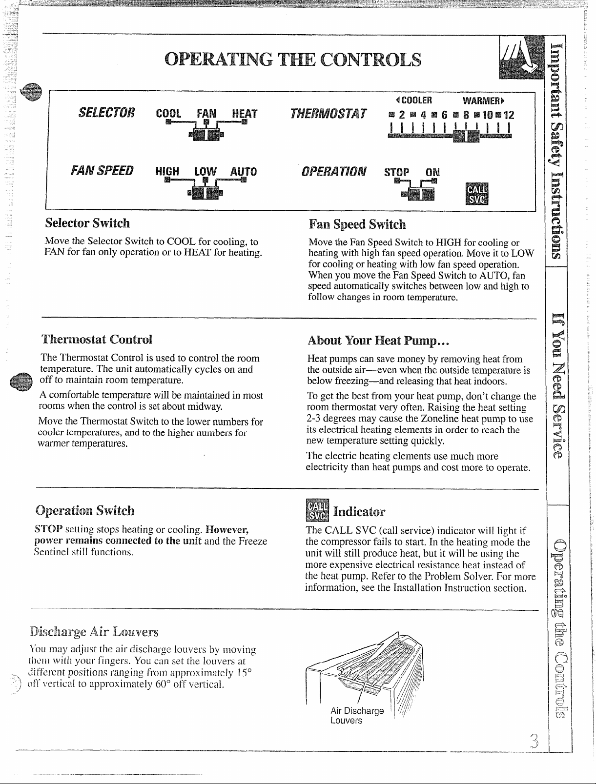
Move the Selector Switch to COOL for cooling. to Movethe Fan Speed Switchto HIGH for coolingor
FAN for fan only operationor to
HEATfor he~ting.
heatingwith highfan speedoperation,Move it t~ LOW
for coolingor heatingwithlowfan speedoperation.
Whenyou movethe Fan SpeedSwitchto AUTO, fan
speedautomaticallyswitchesbetweenlow and highto
followchangesin roomtemperature.
Thermostat control
The Thermostat Control isused to control the room
temperature. The unit automatically cycles on and
off to maintain room temperature.
A comfortabletemperaturewillbe maintainedin most
roomswhen the controlis set aboutmidway.
Move theThermostatSwitch to the lower numbers for
coolertemperatures,and to thehighernumbers for
warmertemperatures.
AboutYour HeatPwp.. .
Heatpumps can save moneyby removing heat from
theoutsideair—even when the outsidetemperatureis
belowfreezing—
To get the best from your heat pump, don’t change the
room thermostat very often, Raising the heat setting
2-3 degrees may cause the Zoneline heat pump to use
its electrical heating elements in order to reach the
new temperature setting quickly.
andreleasing thatheat indoors.
The electric heating elements use much more
electricity than heat pumps and cost more to operate.
operationswitch
ST’OPsetting stops heating or cooling. However,
power remains con~~ectedto tlReunit and the Freeze the compressor fails to start. In the heating mode the
Sentinel sti[lfunctions.
The CALL SVC (call service) indicator will light if
unit wil~still produce heat, but it will be using the
more expensive electrical resistance heat instead of
the heat pump. Refer to the Problem Solver. For more
information, see the Installation Instruction section.
Dise13aE”geAir Louvers
youmay adjLlstthe air discharge louvers by nloving
[!lCIIIwill]your fin:ers. YOUcan set the louvers at
di
Ff’crcn( ~>ositionsranging from approximately 15°
t)fi’~’cr~icalto approximaieiy 600 off verlical,
.——— . .._ ...._=____ —.
P?
x.
J
-.
—..
—-.——.....—. ...
/“
Page 4
~=-=~--
. .
<~..&T:-:qd~~_*~~-*:~7yTA*_q~<~*~z;.>.~.~T=. . . .
,-= .= . ._ ._ -.-.-—.=.. ___
._,_— -—-
-..
.—
.. .
2:.7~--_L ._;. ~
,,-. _.
.— -
:- --
--— ---
.
-.
Am
WRY
CONTROLS
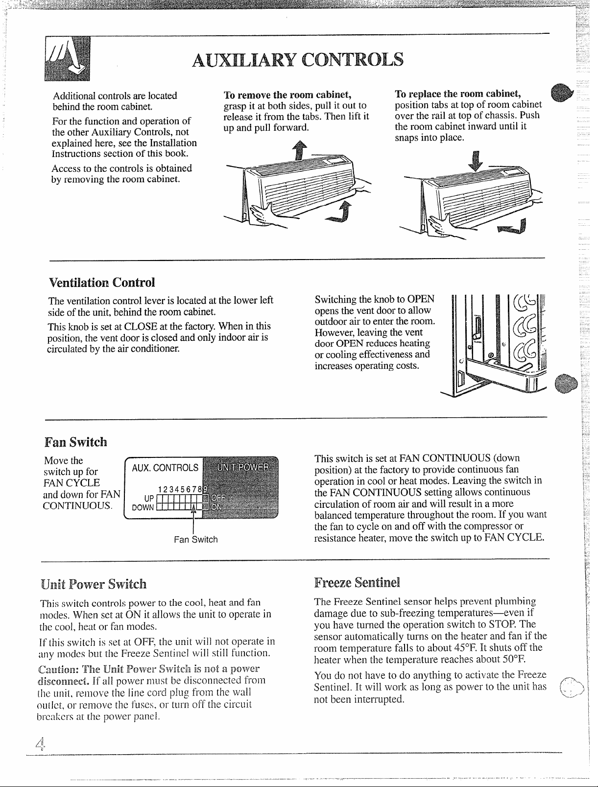
Additionalcontrols are located ‘roremove tile room cabinet,
behindtheroom cabinet.
For the function and operation of
the otherAuxiliary Controls, not
explainedhere, see the Installation
grasp it at both sides, pull it out to
release it from the tabs.Then lift it
up and pull forward.
A
Instructions section of this book.
Accessto the controlsis obtained
by removing theroom cabinet.
ventilation control
Theventilationcontrolleveris locatedat the lowerleft
sideof the unit,behindtheroom cabinet.
Thisknobis setat CLOSE at the factory.When in this
position,the ventdooris closed and only indoor air is
circulatedby the airconditioner.
Switchingtheknob to OPEN
opensthe vent doorto allow
outdoorair to enter+Aeroom.
However,leavingthevent
doorOPEN reducesheating
or coolingeffectivenessand
increasesoperatingcosts.
To replace the room cabinet,
positiontabs at topof room cabinet
over the rail at topof chassis.Push
the room cabinetinward until it
snapsinto place.
.-
G
Fan switch
Movethe
switchup for
FANCYCLE
and downfor FAN
CONTINUOUS.
Fan Switch
UnitPower switch
This switch controls power to the cool, heat and fan
nlocies.When set at ON it allows the unit to operate in
the cool, heat or fan modes.
1[[hisswitch is set at OFF, the unit will not operate in
:iny nlodcs but the Freeze Sentinel will still function.
D
1
This switch is setat FAN CONTINUOUS (down
position)at the factory to provide continuousfan
operationin cool or heat modes. Leaving the switch in
the FAN CONTINUOUS setting allows continuous
circulationof room air and will resultin a more
balanced temperature throughout the room. If yo~~want
the fan to cycle on and off with the compressoror
resistance heater,move the switch up to FAN CYCLE.
\:’
Freeze Sentinel
i
i!
The Freeze Sentinel sensor helps prevent plumbing
damage due to sub-freezing temperatures—even if
you have turned the operation switch to STOP. The
sensor automatically turns on the heater and fan if the
room temperature falls to about 45”F. It shuts off the
heater when the temperature reaches about 50”F.
You do not have to do anything to activate the Freeze _ [
Sentinel. It will work as long as power to the unit has (,,. ‘->~
not been interrupted.
~..#
‘?
i’
1’
:
~.
~
~
\
;
1
~
*
—.—.....——.———
.—
...——-.—
,
Page 5

-.
.. ......—-,. -
..
Forpeak operatingefficiencyanddurabilityof your air conditioner
followthesenecessaryCare and Cleaninginstrl~ctionsregularly.
TurJnthe Zoneiineoff beforec~eaning.
Room cabinet & case
Walshtheroom cabinet andcase finish with mild soap
or detergentand lukewarmwater.
outdoor coil
The coil on the outdoorsideof the unit shouldbe
checked peliodicallyand cleaned if clogged with dirt
or soot from the atmosphere.If extremelydirty, it may
need to be professionallysteam cleaned, a service
availablethroughmany GE serviceoutlets.
Air Filters
The Zoneline air filters inside shouldbe
cleaned at least every 30 days.
The two air filters are located in front
of the air louvers.
I
1
Base Pan
In someinstallationsdirt or other foreign matter may
be blown into the unit from the outsideand settle in
the base pan (the bottom of the unit).
Checkthe base pan periodically and clean it out,
if necessary.
Note: Do notoperatetheair Conditionerwithout
filters in place=If a filter becomes torn or
the
damaged ;t should be replaced immediately
Operating the unit without the filters in place or with
damaged filters will allow dirt and dustto reach the
indoorcoil and reduce the efficiency of the unit.
Replacementfilters are availablefrom your GE
Dealer,Factoly ServiceCenter or authorized
CustomerCare@servicers.
To reinstall the air filter after cleaning, make sure
the word FRONT is facing out. Insert the bottom of
each filter in their slots and push down into place.
11
Allow theilltcrsto dry thoroughlybefore ‘‘:’
rc~~laciilgtllell~.
—. .—.—.-.——...—..—— -----
“.—- —.
,=
‘-:
‘“
—.
——
Page 6

Readthese instructionscompletely and carefully.
lMPORTANT—Observe all governing codes and
ordinances.
lNSTALLEH—Besure to leave these
instructions with the Consumer.
CONSUMER—!(eep these instructions for
future reference.
FOR PERSONAL SAFETY
@Follow National Electrical Code (NEC) and
local codes, ordinances and regulations. All
wiring
—including installation of receptacle,
must be in accordance with these codes.
This unit must be properly grounded.
Do not use an extension cord with this unit.
NEC requires permanent connection for
installations over 250 volts.
NEC requires units controlled by NEC Class
2 low voltage remote controls to be
permanently connected.
Protective devices(fusesor circuitbreakers)
acceptablefor Zoneline installationsare
specifiedon the nameplate of each unit.
Aluminum buildingwiring may pose special
problems--consult a qualified electrician.
Disconnectpower to the air conditioner before
servicingby:
1. Removingthe power cordfrom the wall
receptacle, if ithasone.
2. Retnovingthe branchcircuitfusesor turning
the circuitbreakersoff at the panel.
Before
statiirag the installation. the power to
the direct connect wiring should be OFF.
THEGEZONELINP
ExteriorGrille/Louver**
*
Shipped with the chassis
** Check essential elements list on chassis
*** Line cord connection shown only as example
WALL CASE & GRILLE
~. The RAB70 or 77 Wall Casemust be
properlyinstalledper instructionspacked
with the case.
2. Removethe corrugated stiffenerand the
outdoorprotective panel. Usethe slit inthe
outdoorpanel asa handhold and push out.
Protective
Panel
RoomCabinet*
Slit
“
n
Stiffener
3.
Installthe ExteriorGrillefrom the room side
per instructionpacked with the grille.
—.
....
—..———-———.-----=
Page 7

i
~ERMAN
1. Removeshippingtape,if presentfromthe
roomcabinetandvent door.
ShippingTape’
2. Removethe room cabinetbypullingout at the
bottomto releaseit,then liftit upto clearthe
railalongthe chassistop.
u
3. Slidethechassisintothewallcaseandsecure
withfourscrewsthroughthechassisflangeholes.
4. Reinstallthe roomcabinet byhookingthe top
overthe railalongthe chassistop, then
pushingit inat the bottom.
Thepowerconnectionkitmustbeusedto supply
powertothe Zonelinechassis.Theappropriatekitis
determinedbythe voltage,themeansofelectrical
connectionandthe amperageofthe branchcircuit.
Connectionsof208 or 230 voltcircuitsmaybe with
alinecordkitora permanentconnectionkit.
Connectionsof 265 voltcircuitsmustbewitha
permanentconnectionkit.
Electrical Wiring Wall
Outlets 230/208 volt
Tandem15amp
s:
o
Perpendicular20amp
~f
o
Largotandem 30 amp
0;
o
NECrequirespermanentconnection
forinstallationsover250 volts.
‘“\
‘i
---
Allwiring,includinginstallationofthe receptacle,
be inaccordancewith the NationalElectrical
tmust
Codeand localcodes,ordinancesand regulations.
CONNECTION KIT
g
Page 8

POWERcQNNEcvoN(conti
230/208 Volt Wal!Plug
LineCordKits
RAK315 Tandem 15Amp TD Fuseor Breaker 2.55/2.09 i<vv
FiAK320 Perpendicular 20 Amp TK)fuseor Breaker
RAI<330* LargeTandem
230/208 Voit
Permanent
ConnectionKits CircuitProtectiveDevice @230/208 Volts
RAK415/415L 15 Amp TD Fuseor Breaker 2.55/2.09 KW
RAK420/420L
RAK430/430L* 30 Amp TD Fuse or Breaker 5.00/4.10 I<w
Kitsendingin “L haveflexibleconduitto reachfrom the kitto the knockouthole(above rightsideinspection
plate)inthe RAI<203 Sub-Base.
265 Volt
Permanent HeaterWattage
ConnectionKits CircuitProtectiveDevice @265 Volts
RAK515/515LF 15Amp TD Fuse
RAK517/517LF 15Amp TD Fuse 3.00 KW
RAK520/520LF 20 Amp TD Fuse 3.70 KW
RAK530/530LF* 30 Amp TD Fuse 5.00 KW
I<itsendingin “LF”
plate) inthe RAK203 Sub-Baseand have an Integral Fuse.
*f~ot recommended for useon 6000 BTUH Units.(If thisconnection kit isuseditwill providea maximum
heat of 3.45 I<Wat 230 voltsand 3.7 I<Wat 265 volts.)
Configuration CircuitProtectiveDevice @230/208 Volts
20 Amp TD Fuseor Breaker 3.45/2.82 I<W
have flexible conduit to reach from the kit to the knockout hole (above right sideinspection
flu@q
HeaterWattage
3.45/2.82 KW
30 Amp Fuseor Breaker 5.00/4.10 KW
HeaterWattage
1.70 KW
The dischargeair louverscan be adjusted
with the fingersto different positionsranging
from approximately 15° off verticalto
approximately 60° offvertical.
Air Discharge Louvers
] “1
Page 9

4
REMOTECONTROL– 5100SERIES
Theunitmaybe controlledeitherbythe unit
mountedcontrolsorbychangingthe “CONTROL
switch(locatedbehindtheAuxiliaryControlcover
plate) to “REMOTE”and connecting the unit to a
6 wire Class2 remotethermostat(GEModel
RAK147Aor RAI<I52A orequivalent).
No external voltage should be applied to the unit
throughthe remote thermostat terminals.
CONTROL
[u]
UfilT
-,,
-.-
---.-....—
ADJUSTMENTSANDAUXILIARYCONTROLS AVAILABLEWITH
THE ROOM CABINET ANDCONTROLBOXFRONTPLATEREMOVED
5100 SERiES
AuxiliaryControlPanel
CLASS2REMOTE
.@@@e@@
BY WGRC
Fan Switch
TheCLASS2 REMOTE,CDCterminalsand
remotecontrolarelocatedbehinda coverplatewith
the auxiliatycontrols.Toremovethe plate, remove
andsavethe screwsthat holdthe plateto the unit.
IMPORTANT After the wire connections are
completed, replace the plate to prevent damage
tothe unit or personal injury.
REMOTE
-aa
.,....,’.=
.....—-.———!-=r—-.--=-—...=.--—-----
2 STAGEHEAT
1 STAGE COOL
MANUAL THERMOSTAT
I
~
BY WGRC
CLASS 2 REMOTE
LOWVOLTAGE
TERMINALONZONEI.INE
-1”= “ 1
— .—..... .“,.,-,
- ..——
CDC
p]
J
The unitmay be connectedto a switchat the
frontdesk.When the switchisOPENthe unitis
operable.When the switch isCLOSED, theunit is
made inoperative.Connectthe wiresfrom the
centralcontrolsystemto the “CDC”terminals
locatedon the panelbehindthe roomcabinet.
Followthe recommended wire sizinginthe table
below.Two wires must be usedfrom each CDC
switchto each individualunit.Do not usea
common bussinthe CDCwiring. A 24 volt
transformeriscontainedwithin the unitand no
externalvoltage shouldbe appliedto the unit
throughthe CDCterminals.These terminalsmay
alsobe usedasan interfacefor othersystems
usedto controlthe unit,suchasinfrared
detectors,key-activatedsystems,etc.The Freeze
Sentinelremains inan active modeto helpprotect
againstlow temperature damage eventhough the
unitmay be “OFF”at the centralcontrollocation.
Recommended
Wire Size for Central Desl(
Control installation
WireSize#AWG
#24
#22
#20
#18
#16
Thisswitch controlspower to the cool, heat
andfan modes. It isset inthe ON positionat the
factoryto allow the air conditioner to operate in
these modes.
Ifthis switch isset at OFF,the unitwill not
operate in any modes but the FreezeSentinel
will stillfunction.
MaximumAl!owabieLength
400 ft.
600 ft.
900 ft.
1500ft.
2000 ft.
Caution: The UNITPOWERswitch is
not a povverdisconnect,
disconnected from the unit remove the line cord
plugfrom the outlet, or remove the fuses,or
turn offthe circuit breakers at the bui!ding
power panel, or unplug the power connector
from the chassis.
ifall power must be
Page 10

Temperaturelimitingcanreduceenergycosts
(--’-’”
bylimitingthe lowesttemperaturethat canbe
obtainedoncoolingandthe highesttemperature
thatcanbe obtainedonheating.Temperature
limitingiscontrolledbysettingthe firstsixsmall
verticalslideswitchesin a stripof ninethat are
mountedonthe auxiliarycontrolcircuitboard.
Thefirstthreeare usedto selectcoolingrange
limitsandthe nextThreeare usedto selectheating
rangelimits.
FanSwitch
COOLINGLIMITS
LIMIT SW!TCH
UP
NONE 64t085
1 66t085
l&2 68t085
2 70t085
2&3
l&2&3
l&3 75 to 85
3
HEATINGLIMITS
LIMIT SWITCH TEMP RANGE
UP
NONE — 60t085
4 60
4&5 60 to 76
5 60 to 74
58L6
4&5&6
4&6 60t069
TEMP RANGE
F
71 to85
73t085
77t085
F
to 80
60t073
60t071
6 60t067
[ The unithasa Diagnosisfeature.When the number
~ 8 switch ismoved to UP,[he unit will go Ihrough an
~ operations checl( of all components. This cheek is
? completed in approximately one minute.
:~
:1
FANSWITCH
Thisswitchissetat DOWNatthefactoryto
providecontinuousfanoperationincoolorheat
modes.Leavingthe switchinthe DOWNsetting
allowscontinuouscirculationof roomairandwill
resultina moreuniformtemperaturethroughout
theroom.Settingtheswitchat UPwill causethe
fantocycleonandoffwith thecompressoror
resistanceheater.
FREEZESENTINEL
The unitisequippedwith a sensorthat
automaticallyturnson the resistanceheaterand
fan ifthe roomtemperature, assensedat the unit,
dropsto approximately45” F.andwill turnthe
heateroffwhen the temperature reachesabout
50”F.The FreezeSentinelsystemhelpsprevent
damage dueto sub-freezingtemperaturesand will
operateregardlessofthe mode settingof the unit.
FreezeSentinelisactiveAS LONGAS POWERTO
THE UNIT HAS NOTBEENINTERRUPTED.
VENT%LATIONCONTROL
The VENTILATION control leverislocatedat
the lower left sideof the unit, behindthe
room cabinet.
This levercontrolsthe
vent door and isset inthe
CLOSEpositionat the
factory sooutdoor airwill
not enter the rootnthrough
the vent and only indoor
air iscirculated bythe
air conditioner.
Movingthe leverto OPEN
opensthe vent doorand
drawsoutdoorairthrough
the airconditionerandinto
the room. Leavingthevent
doorOPENduringextreme
temperatureconditionsreducesheatingor cooling
effectivenessand increasesoperatingcosts.
:_..—-
.-
.1
\
_,. ...
Page 11

0Keep theair filter clean.
v
(See Care and Cleaningsection.)
QFor mostefficientoperation,
keep vent in closed position.
~Don‘tlettheroomgettoohotortoo
cold.Wheneverpossible,turnthe
unit on beforetheroomheatsupor
coolsoff,Ifyoudon’t,theZoneline
willtake longertoproducethe
desiredcomfortcondition.
e
~Keep windowsand doorsclosed.
Conditionedair escapeswhen
they’reopen.
eKeepfurnacefloorregistersand
coldair returns
coolingis desired,Conditionedair
can easilyescapethroughthem.
eDon’tlet drapesor furniture
block the front of the Zoneline.
This will restrict airflow when
the unit is operating.
closedwhen
It’sbest to operate yourZoneline
at high speedduringextremely
hot or cold weather.
*Keepoutdoorcondensercoilclean.
(SeeCareand Cleaningsection.)
UITurn Zonelineoff during
vacationsor extendedabsences.
~ms~lo~s?
USE THISPROBLEM SOLVER
PROBLEM
ZONELINE DOES
NOT OPERATE
ZONELINE “DOES NOT
COOL OR HEAT
AS IT SHOULD”
“~u~N]~~” ODOR
AT S“rART
EIEATING
OPERATION
oI’ERATiNG
OF
SOUNDS
POSSIBLECAUSE
~Power cord not plugged in,fuse blown, or circuit breaker tripped.
*Unit is waiting for compressor overload protector to reset.
~Curtains,blinds or furniture blocking the front
oftheairconditionerwillrestrictair flow.
~Themostat Controlmaynot be sethi,ghenough.Turnthecontroltoa lower
orhighernumber.(Note:TemperatureLimitermaybelimitingthe
temperaturerange.)
9Dirtyairfilterblockingairflow.Filtershouldbe cleanedatleastevery
30days.Seeinstructionsincleaningsection.
~Room mayhavebeenveryhotorverycoldwhentheZonelinewasfirst
turnedon.Allowtimeforit to cooldownor warmup.
~Ventilationcontrolmaybesetat OPENposition,allowingoutsideair
toentertheroom.
~Dustonthesurfaceofthe heatingelementcancause“aburning”odor
atthebeginningoftheheatingoperation.Thisodorshouldquicklyfade.
~Relayclicksmaybe heardwhenthecompressororfan cycleson andoff.
This is normal.
QFan runs
continuouslywhentheunitis operatingunlesstheFan Switchbehind
theroomcabinetis setat FANCYCLE.T’henthe fancycleson andoff
withtile conlpressor.
Page 12

VJe’11Be There
With
assurancethatfyou everneed informationor assisbnce
fromGE,wdIlbe tl~ere.Allyou l~aveto do iscall–toll-free!
—
AGE consumer serviceprofessional
willprovideexpertrepairservice,
schedu~eciatatimethat’sconvenient
foryou.NlanyGEConsumerService
company-operatedlocationsoffer
youselx~icetodayortomorrow,or at
yourconvenience(7:00a.m. to7:00p.m.
tveekdays,9:00a.m.to2:00p.m.Saturclays).Ourfi~cto~-trainedtechnicians
knowyf)urapplianceinsideandouts{)rnos[repairscanbehandledinjust.
one visit.
the purchaseofyour newGEappliance,receivetie
Youcanhavetie securefeelingthat
GEConsumerServicewillstillbe
thereafteryourwarrantyexpires.PurchaseaGEcontractwhileyourwarrantyisstillin effectandyou’llreceive
asubstantialdiscount.Withamultipleyearcontract,you’re assuredOffuhlre
serviceattoday’sprices.
WhateveryourquestionaboutanyGE
majorappliance,GEAnswerCenter@
informationserviceisavailableto
help.Yourcall–andyourquestion–
willbeansweredpromptlyand
courteously.Andyoucancallany
time.GEAnswerCenter”serviceis
open24hoursaday,’7daysa week,
TelecommunicationDevicefor theDeaf
,’.,... 0,.W .,”.. ,., ”,,m “,.. .“.,.
,.,, .“””,0 ,,,0.,
SCCTION A.A
“,’O, ”.06,:0
,Chtr t.!
Upon request,GEwillprovideBraille
controlsfor avalietyofGE
ancla brochure to assistin plannin~ a
appliances,
barrier-freekitchenfor personswith
limitedmobility.To obtaintheseitems,
freeof charge,call800,626.2000.
[;onsumerswithimpairedhearing
orspeech]vhohaveaccessto aTDD
or aconventionalteletypewriterInay
8oo-TDD-Gm.c (800-833-43:22)
call
torequestinformationor service.
Page 13

t
I
I
I
I
Save proofof original purchasedate such as your sales slip or cancelled checkto establishwarrantyperiod.
YOURGE ZONELINEAIRCONDITIONER
WARRANTY
WHATISCOVERED
WHATIs NOTCOVERED
=Service trips to teach you
how to use the product.
Readyour Useand Care material.
If you then have any questions
about operating the product, please
contact your dealer or our
Consumer Affairs office at the
address below, or call, toll free:
1
GE Answer Center@
800.626.2000
consumer information service
1
FULL ONE-YEARWARRANTY
Forone yearfrom date of original
purchase,we will provide,free of
charge,partsand on-site service
laborto repairor replaceany pafi
of the room air conditionerthat
tails becauseof a manufacturing
defect,
FULL FIVE-YEARWARRANTY
Forfiveyearsfromthedateof
originalpurchase,wewillprovide,
freeofcharge,partsandon-site
servicelaborto repairorreplac~
anypart of thesealed refrigerating
system(thecompressor,condenser,
evaporatorandallconnecting
tubing)thatfailsbecauseof a
manufacturingdefect.
Foreach of theabovewarranties:
Transportationexpenseto and
from a service shop and shop
service labor if requiredwill be
free of charge.
~Improper installation. * Failureof the productresultingfrom
ifyouhaveaninstallationproblem,
orif theairconditionerisof improper
coolingorheatingcapacityforthe
intendeduse,contactyourdealer
orinstaller.Youareresponsible
forprovidingadequateelectrical not corrosion-protected.
connectingfacilities.
@Replacement of fuses or
resetting of circuit breakers. accident, fire, floods or acts of God.
@In commercial locations labor
necessaryto move the unit to a
location where it is accessible for CONSEQUENTIAL DAMAGES.
service by an individual technician.
This warranty is extendedto
the original purchaserand
succeedingownerfor products
purchasedfor use in the 48
mainlandstates, Hawaiiand
Washington,D.C.InAlaskathe
warranty is the sameexceptthat it
is LIMITED becauseyou must pay
to ship the productto the service
shop or for the servicetechnician’s
travel costs to your home.
All warranty servicewill be
provided by our FactoryService
Centers or by our authorized
Customer Care” servicersduring
normal working hours.
Shouldyour applianceneed
service,during warrantyperiod
or beyond, call 800-GE-CARES
(800-432-2737).
modificationsto the productor due
to unreasonableuse including
failure to providereasonable
and necessay maintenance.
~Failure due to corrosion on models
QDamage to the product caused by
improper power supply voltage,
WARRANTOR IS NC?T
RESPONSIBLE FOR
any
I
I
i
~
;
U
,,
Some statesdo not allow the exclusion or limitation of incidental or consequential damages, so the above limitation or exclusion
may not apply to
To know what your legal rights are in your state, consult your local or state consumer affairs office or your state’s Attorney General.
you.Thiswarrantygivesyou specificlegalrights,andyoumayalsohaveotherrightswhichvaryfrom state to state.
Warrantor: General ElectricCompany
!-ffuvther help is needed concerning this warranty, write:
Ma~lager—Consumer Affairs, GE Appliances, Louisville,I(Y40225
 Loading...