

Page 1

Indoor/Outoor
Antenna
User’s Manual
Page 2

2
WARNING: INSTALLATION OF
THIS PRODUCT NEAR POWER
LINES IS DANGEROUS, FOR
YOUR SAFETY, FOLLOW THE
INSTALLATION DIRECTIONS.
WATCH FOR WIRES! YOU CAN
BE KILLED IF THIS ANTENNA
COMES NEAR ELECTRIC POWER
LINES. READ INSTRUCTIONS!
Page 3

3
TABLE OF CONTENTS
IMPORTANT SAFETY INSTRUCTIONS ....................................................4
SELECT YOUR INSTALLATION SITE .........................................................5
CHOOSE A MOUNT TYPE ............................................................................6
ANTENNA ASSEMBLY & INSTALLATION ................................................7
ANTENNA GROUNDING & CONNECTION ........................................ 10
ANTENNA HELPFUL TIPS .........................................................................13
Page 4

4
IMPORTANT SAFETY INSTRUCTIONS:
• NEVER touch ANYTHING or ANYONE in contact with a
power line. You can be electrocuted. In case of an accident
or emergency, call 911 immediately for help.
• INSPECT your installation site carefully for power lines.
Make sure there is no possibility the antenna, its
mounting structure or your ladder can come into
contact with power lines. Be sure to consider what can go
wrong during installation.
• KEEP the distance between power lines and the antenna
and its mounting structure at least 2 times the combined
height of the antenna and mounting structure added
together. In the event the antenna falls, during or after
assembly, there must be sufficient distance to ensure it
does not come into contact with the power lines.
• KEEP your ladder, antenna and antenna mounting
structure (such as mast, pole, mount) far away from power
lines at all times.
• GROUND the antenna and the antenna mounting
structure in accordance with the NEC electrical
code, all state and local electrical code requirements
• COMPLETE the antenna assembly on the ground prior to
mounting.
• DO NOT use a metal ladder or install the antenna on a
windy day. If the antenna or mast starts to fall, allow it to
fall. Do not attempt to catch the antenna.
• EXERCISE caution when working on a roof.
• INFORM others of the danger of touching power lines or
touching other objects in contact with power lines.
• CONTACT a professional installer in your area to do the
antenna installation if you are unsure how to safely install
and ground this antenna.
Page 5

5
SELECT YOUR INSTALLATION SITE
Key things to consider in choosing the antenna installation
site are:
1) Choose a SAFE location that is far away from power lines.
Keep the distance between power lines and the
antenna and its mounting structure at least 2 times the
combined height of the antenna and its mounting structure
added together. Refer to the Important Safety
Instructions.
2) Determine the location of the broadcast towers in your
area. You will need to aim the antenna toward
those towers. There are online resources such as
www.antennaweb.org that can help you identify
the location of your local broadcast towers and
the channels you can expect to receive.
3) Check your local, city and state building and electrical
codes. Make sure your planned installation is safe and in
compliance with all applicable codes, rules and
regulations.
Page 6

6
CHOOSE A MOUNT TYPE:
Some examples of common mounting options are shown
below.
1) Outdoor/Attic Wall Mount:
2) Outdoor Mount (under eave):
3) Indoor Wall Mount:
IF YOU ARE UNSURE OR DO NOT FEEL CAPABLE
OF INSTALLING THIS ANTENNA, CONTACT
A PROFESSIONAL INSTALLER IN YOUR AREA.
Page 7
7
ANTENNA ASSEMBLY & INSTALLATION:
Thank you for purchasing the GE 34140 Indoor/Outdoor
Antenna. This antenna is a sturdy, high-performance
antenna designed to receive UHF and VHF broadcasted
signals. The small, compact design allows you to install the
antenna almost anywhere on the inside or outside of your
house.
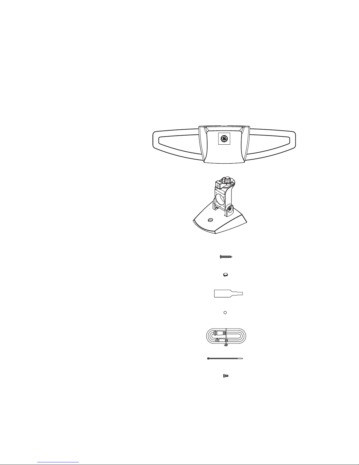
PARTS LIST:
1) Antenna 1 ea.
2) Antenna Base 1 ea.
3) Wood Screw 2 ea.
4) Screw Cover 2 ea.
5) Rubber Boot 1 ea.
6) Rubber Foot Pad 4 ea.
7) Coax Cable 6’ 1 ea.
8) Zip Tie 1 ea.
9) M5 Bolt 1 ea.
Page 8
8
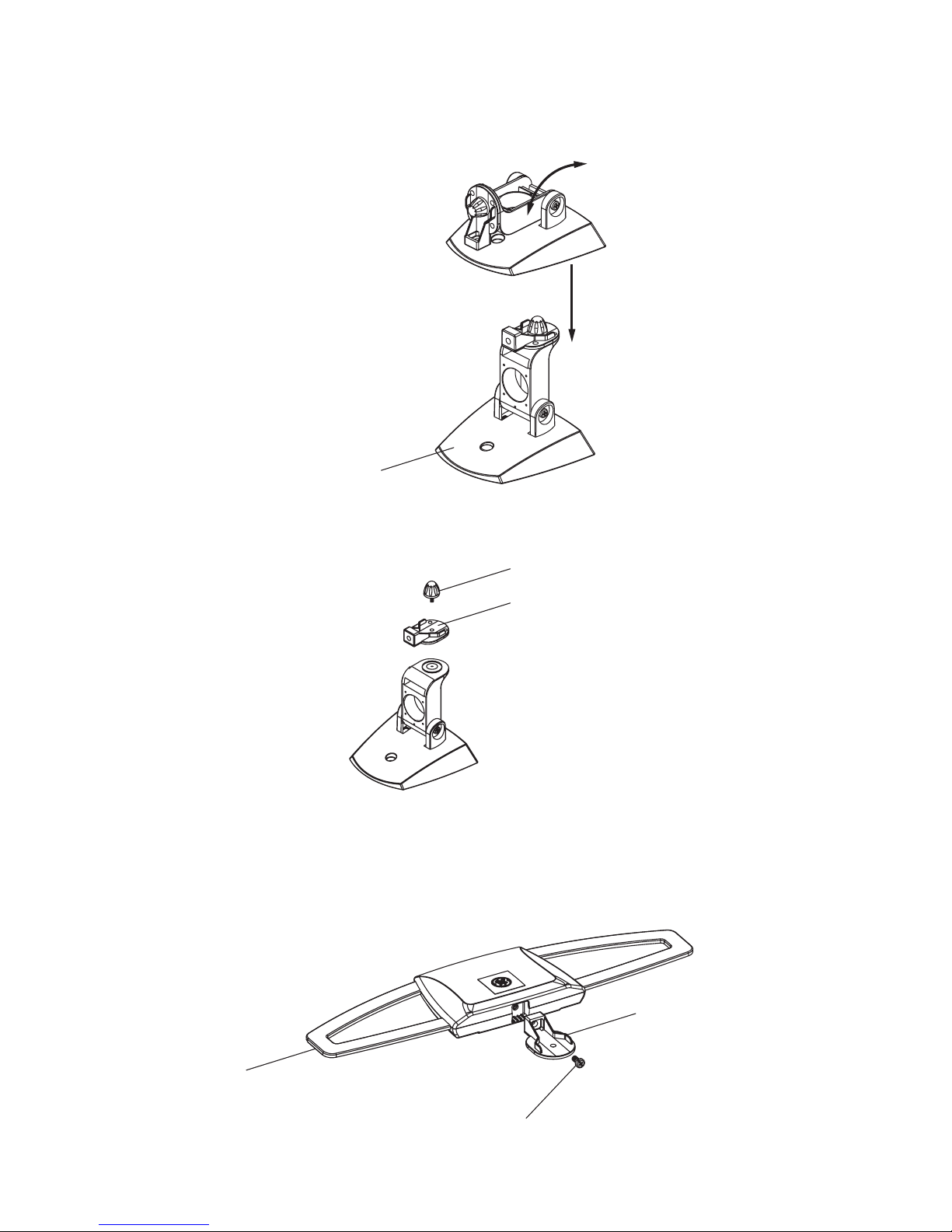
ASSEMBLING THE ANTENNA:
1) Rotate the Antenna Base into upright position.
2) Remove the Thumb Screw and Mounting Bracket from
the Antenna Base.
3) Attach the Mounting Bracket to the antenna using the
M5 Bolt.
Antenna
Mounting Bracket
Thumb Screw
M5 Bolt
Mounting Bracket
Base
Page 9

9
4) Attach the antenna to the Antenna Base with the Thumb
Screw.
5) Select the mounting method you prefer and place the
antenna in the desired location.
a) Outdoor Wall Mount
b) Outdoor Under Eave
c) Attic Mount
d) Indoor Wall Mount
e) Table Mount
Note: Wood screws are provided. Rubber foot pads are
also provided for table mounting.
6) Connect the coax cable from the antenna to your TV.
Note: For outdoor installations, the National Electric
Code requires your antenna to be properly grounded.
Refer to the Antenna Grounding & Connection section
for detailed instructions.
7) Tighten the screw shown below to secure the antenna.
Use the Screw Covers to cover the screw holes on the
Antenna Base.
Thumb Screw
Screw
Page 10

10
8) SCAN FOR CHANNELS ON YOUR TV. This step is very
important. Your TV will NOT receive signals from the
antenna without doing a channel scan. See your TV’s
menu screen for this process or refer to the instruction
manual that came with your TV.
Note: It is important to repeat this process and re-scan
for channels anytime you move or re-position the
antenna. It is also a good practice to repeat this
process from time to time in case there are changes
to the available TV signals in your area. If you ever
lose a channel, a re-scan may be all that is needed to
pick up that station again.
9) Contact us at 1-800-654-8483 if you need assistance.
Antenna Grounding & Connection
The National Electric Code (NEC) requires your outdoor
antenna installation to be properly grounded. This involves
grounding the antenna. This helps protect you and your
property in the event of static build up on the antenna or
lightning near your home.
Note: If you previously had a satellite or cable system
installed at your home, you may be able to use some of the
parts from this system for your antenna installation.
1) Connect one end of a coax cable to the antenna and
the other end to a 75 ohm grounding block (not provided).
Below (Fig. 1a) is an example of a 75 ohm grounding
block.
Fig. 1a
Page 11

11
If you make your own coax cable, be sure to slide the
Rubber Boot over the cable before you place the
connectors on the cable. Once you have attached the
cable to the antenna, slide the Rubber Boot into the
round channel on the Antenna.
2) If you are using a pre-built cable that has connectors,
follow these steps.
i) Cut 4 slits spaced evenly apart at the narrow tip of the
provided Rubber Boot approximately ¼” in length. (Fig. 1b)
Fig. 1b
ii) Run the coax cable through the narrow end of the
Rubber Boot and attach the cable to the antenna.
iii) Slide the Rubber Boot into the round channel on the
antenna.
iv) Using the Zip Tie, wrap the tie around the
narrow tip of the Rubber Boot, around the four slits
and pull the tie tight.
3) Use a second coax cable and connect one end to
mating port of the first coax cable on the 75 ohm
grounding block and run the other end into your home
for making the connection to your TV. The 75 ohm
grounding block needs to be placed as close as possible
to the point where the second coax cable enters your
home.
Note: Leave enough slack in the coax cable to create a
drip loop so that moisture cannot enter the house. You
will also need to seal the coax cable entry point into
your house with an exterior caulk.
Page 12

12
4) Ground the 75 OHM Grounding Block:
Connect a #8 aluminum or #10 grounding wire to a
screw terminal provided on the 75 ohm grounding block.
Connect the other end of the wire to an acceptable
building ground location.
Examples of acceptable building grounding locations are:
• The building or structure grounding electrode system
as covered in 250.50 in the NEC.
• Grounded interior metal water piping system, within
5ft. from its point of entrance to the building.
• Grounded nonflexible metallic power service raceway.
• Service equipment enclosure, the grounding electrode
conductor or the grounding electrode conductor metal
enclosure of the power service.
• An 8-foot grounding rod driven into the ground can be
used as long as it is connected to the central building
ground by a #6 or heavier bonding wire.
Be sure to double check all your connections after your
installation is complete. Ensure there are good electrical
connections of your grounding wires and coax cables. See
Fig. 2 below for an example of a properly grounded antenna
installation.
Example of Antenna Grounding
as per NEC - National Electrical Code
ELECTIC SERVICE METER PANEL
POWER SERVICE GROUNDING ELECTRODE
SYSTEM (NEC ART 250. PART H)
GROUNDING CONDUCTOR
(NEC SECTION 810-21 )
GROUND CLAMP
75 OHM GROUNDING BLOCK
(NEC SECTION 810-20)
ANTENNA COAX
RAIN DRIP LOOP FOR THE COAX TO TV
Fig. 2
If you are unsure how to properly ground your antenna
installation, contact a professional installer in your area.
Fig. 2
Page 13

13
ANTENNA REMOVAL
Inspect the area carefully for power lines. Look for any new
power lines that may have been installed. Make sure there
is no possibility the antenna, its mounting structure or your
ladder can come in contact with power lines. Be sure to
consider what can go wrong during the antenna removal.
Repeat the steps for antenna installation but in reverse order.
ANTENNA HELPFUL TIPS
Maximize the number of channels you receive by aiming the
antenna in different directions to see which position provides
the best reception and the maximum number of channels. Be
sure to run a new channel scan for each position. Refer to the
instruction manual that came with your TV if you are not sure
how to do this.
Position or mount the antenna as high as possible for the
best performance. Point the antenna towards the broadcast
towers in your area.
Visit www.antennaweb.org or www.dtv.gov and look for the
DTV Reception Maps to determine the available television
stations and location of the broadcast towers in your area.
FOR FURTHER ASSISTANCE, CALL 1-800-654-8483 FOR
TECHNICAL SUPPORT.
Page 14

14
MADE IN CHINA
GE is a trademark of General Electric Company and
is under license by Jasco Products Company LLC,
10 E. Memorial Rd., Oklahoma City, OK 73114.
This Jasco product comes with a limited-lifetime
warranty. Visit www.byjasco.com for warranty
details.
Questions? Contact us at 1-800-654-8483 between
7:00AM—8:00PM CST.
34140 V4
3-19-2018
Page 15

15
Page 16

16
Page 17

Antena GE para
interiores y
exteriores.
Manual de usuario
Page 18

18
ADVERTENCIA: INSTALAR ESTE
PRODUCTO CERCA DE CABLES
ELÉCTRICOS ES PELIGROSO.
POR SU SEGURIDAD, SIGA
LAS INDICACIONES DE
INSTALACIÓN.
¡PRESTE ATENCIÓN A LOS
CABLES ELÉCTRICOS! EL
CONTACTO DE ESTA ANTENA
CON ALGÚN CABLE ELÉCTRICO
PUEDE CAUSARLE LA MUERTE.
¡LEA LAS INSTRUCCIONES!
Page 19

19
ÍNDICE
INSTRUCCIONES DE SEGURIDAD IMPORTANTES ...........................20
SELECCIONE EL SITIO DE LA INSTALACIÓN ...................................... 21
ELIJA UN TIPO DE MONTAJE ..................................................................22
INSTALACIÓN Y ARMADO DE LA ANTENA::
Cómo ensamblar la antena ................................................................... 23
INSTRUCCIONES DE ENSAMBLADO:
Conexión a tierra del montaje de la antena ................................... 26
SUGERENCIAS ÚTILES RELACIONADAS CON LA ANTENA ..........30
Page 20

20
INSTRUCCIONES DE SEGURIDAD IMPORTANTES:
• NUNCA toque NADA ni a NADIE que esté en contacto
con un cable eléctrico. Podría electrocutarse. En caso de
accidente o emergencia, llame al 911 de inmediato para
obtener ayuda.
• INSPECCIONE el sitio de la instalación cuidadosamente
para ver si hay cables eléctricos. Asegúrese de que no haya
ninguna posibilidad de que la antena, la estructura sobre
la que está montada o su escalera puedan tomar contacto
con algún cable eléctrico. Piense en todo aquello que
posiblemente pudiera salir mal durante la instalación.
• MANTENGA distancia entre los cables eléctricos y la
antena y su estructura de montaje. Tal distancia debe ser
igual a por lo menos dos veces la altura combinada de la
antena y la estructura de montaje sumadas. En caso de que
la antena se caiga durante la instalación o después, debe
haber distancia suficiente para garantizar que no tome
contacto con ningún cable eléctrico.
• MANTENGA la escalera, la antena y la estructura de
montaje de la antena (como el mástil, el poste, el montaje)
lejos de los cables eléctricos en todo momento.
• CONECTE A TIERRA la antena y la estructura de montaje
de la antena de conformidad con el Código Estadounidense
de Normas de Electricidad (NEC) y todos los requisitos de los
códigos eléctricos estatales y locales.
• COMPLETE el montaje de la antena en el suelo antes de
montarla.
• NO use una escalera de metal ni instale la antena un día
ventoso. Si la antena o el mástil comienzan a caerse, déjelos
caer. No intente agarrar la antena.
• TENGA cuidado al trabajar sobre un techo.
• INFORME a otras personas de los peligros de tocar
los cables eléctricos u otros objetos que puedan estar en
contacto con una línea eléctrica.
• LLAME a un instalador profesional de su zona para que
instale la antena si no está seguro de cómo instalar y
conectar a tierra esta antena de manera segura.
Page 21

21
SELECCIONE EL SITIO DE LA INSTALACIÓN
Aspectos clave que debe tener en cuenta al elegir el lugar en
donde instalará la antena:
1) Seleccione un lugar SEGURO que esté alejado de los cables
eléctricos. La distancia entre los cables eléctricos y la
antena con su estructura debe ser, por lo menos, igual a
dos veces la altura combinada de la antena y la estructura
sumadas. Consulte las Instrucciones de seguridad
importantes.
2) Establezca la ubicación de las torres de transmisión de su
zona. Deberá apuntar la antena hacia esas torres. Puede
consultar recursos en línea, como www.antennaweb.org,
para saber cómo identificar la ubicación de las torres de
transmisión locales y los canales que puede recibir.
3) Consulte los códigos eléctricos y de construcción de su
área, ciudad y estado. Asegúrese de que la instalación
que planifica hacer es segura y que cumpla con todos los
códigos y todas las normas y reglamentos.
Page 22

22
ELIJA UN TIPO DE MONTAJE:
A continuación, se muestran algunos ejemplos de las
opciones de montaje más comunes.
1) Montaje sobre pared de ático o
pared en exteriores:
2) Montaje en exteriores (debajo del alero):
3) Montaje sobre pared en interiores:
SI NO ESTÁ SEGURO DE CÓMO INSTALAR ESTA ANTENA O
CREE QUE NO PUEDE HACERLO USTED MISMO, CONTACTE A
UN INSTALADOR PROFESIONAL DE SU ZONA.
Page 23

23
INSTALACIÓN Y ARMADO DE LA ANTENA:
Gracias por adquirir la antena GE 34140 para interiores y
exteriores. Esta antena es resistente y de alto rendimiento,
diseñada para recibir las señales transmitidas de UHF y VHF.
Su diseño pequeño y compacto permite instalar la antena
en prácticamente cualquier parte en el exterior o interior de
su casa.
LISTA DE PARTES:
1) Antena (1)
2) Base de la antena (1)
3) Tornillos para madera (2)
4) Cubre tornillo (2)
5) Manga de goma (1)
6) Almohadillas de goma cubre base (4)
7) Cable coaxial de 6’ (1)
8) Presilla (1)
9) Tuerca M5 (1)
Page 24

24
Soporte de montaje
Tornillo de cabeza estriada
Tuerca M5
Base
CÓMO ENSAMBLAR LA ANTENA:
1) Gire la base de la antena en posición vertical.
2) Quite el tornillo de cabeza estriada y el soporte de
montaje de la base de la antena.
3) Fije el soporte de montaje a la antena por medio de la
tuerca M5.
Antena
Soporte de montaje
Page 25

25
4) Fije la antena a la base de la antena con el tornillo de
cabeza estriada.
5) Elija el método de montaje que prefiera y coloque la
antena en el lugar deseado.
a) Montaje sobre pared en exteriores
b) Exteriores debajo del alero
c) Montaje en el ático
d) Montaje sobre pared en interiores
e) Montaje sobre mesa
Nota: se incluyen los tornillos para madera.
Se incluyen las almohadillas de goma cubre base para
montaje sobre mesa.
6) Conecte el cable coaxial de la antena al TV.
Nota: para instalaciones en exteriores, el Código
de Normas de Electricidad exige que la antena esté
debidamente conectada a tierra. Consulte la sección
Conexión y Puesta a tierra de la antena para obtener
instrucciones detalladas.
7) Ajuste el tornillo que se muestra a continuación para
asegurar la antena. Use los cubre tornillos para cubrir
los orificios de los tornillos en la base de la antena.
Tornillo de cabeza estriada
Tornillo
Page 26

26
8) EXPLORE LOS CANALES EN SU TV. Este paso es muy
importante. Su TV NO recibirá señales de la antena si no
se realiza una exploración de canales. Consulte el menú
en pantalla de su TV para ver este proceso o el manual de
instrucciones que viene con el TV.
Nota es importante repetir este proceso y volver a
explorar los canales cada vez que traslade o cambie
de posición la antena. Es ideal repetir este proceso
periódicamente por los posibles cambios en las señales
de TV disponibles en su área. En caso de no recibir la
señal de un canal, solo es necesario volver a explorar
los canales para volver a captarla.
9) Llámenos al 1-800-654-8483 si necesita asistencia.
Puesta a tierra y conexión de la antena
El Código Estadounidense de Normas de Electricidad (NEC)
exige que la antena exterior esté debidamente conectada
a tierra. Esto involucra la puesta a tierra de la antena. Eso
ayuda a protegerlo a usted y a proteger su propiedad en caso
de que haya acumulación de estática en la antena o de que
caiga un rayo cerca de su casa.
Nota: si ya tiene un sistema satelital o de cable instalado
en su casa, quizás pueda utilizar algunas partes de ese
sistema para la instalación de esta antena..
1) Conecte un extremo del cable coaxial a la antena y el
otro extremo a un bloque de conexión a tierra de 75 ohm (no
se incluye). A continuación (Fig. 1a), se muestra un ejemplo de
un bloque de conexión a tierra de 75 ohm.
Page 27

27
Fig. 1a
Si construye su propio cable coaxial, asegúrese de
deslizar la manga de goma sobre el cable antes de
colocar los conectores sobre el cable. Una vez que haya
conectado el cable de la antena, deslice la manga de
goma dentro del canal redondo de la antena.
2) Si emplea un cable preconstruido con conectores, haga
lo siguiente:
i) Corte cuatro ranuras a una distancia uniforme en el
extremo estrecho de la manga de goma suministrada de
aproximadamente ¼” (6 mm) de largo. (Fig. 1b)
Fig. 1b
ii) Pase el cable coaxial por el extremo estrecho de la
manga de goma y conecte el cable a la antena.
iii) Deslice la manga de goma dentro del canal redondo
de la antena.
iv) Tome la presilla y enrósquela alrededor del extremo
estrecho de la manga de goma, alrededor de las cuatro
ranuras y ajústela bien.
3) Emplee otro cable coaxial, conecte un extremo al orificio
del primer cable coaxial que coincide en el bloque de
conexión a tierra de 75 ohm y tienda el otro extremo
hasta el interior de la casa para conectarlo a la TV. Debe
colocar el bloque de conexión a tierra de 75 ohm tan
cerca como le sea posible del punto de entrada a la casa,
del segundo cable coaxial.
Page 28

28
Nota: el cable coaxial debe tener holgura suficiente
para formar un lazo de goteo a fin de que la humedad
no entre en la casa. Deberá sellar la entrada del cable
coaxial en su casa con una masilla para exteriores.
4) Conecte a tierra el bloque de conexión a tierra de 75
ohm: conecte un cable de conexión a tierra N.º 10 o de
aluminio N.º 8 a un terminal roscado en el bloque de
conexión a tierra de 75 ohm. Conecte el otro extremo
del cable a un lugar de conexión a tierra aceptable de la
construcción.
Los siguientes son ejemplos de puntos de conexión a tierra
aceptables de una construcción:
• El sistema de electrodos con conexión a tierra de la
estructura, la construcción o el edificio, tal como se
detalla en 250.50 del Código NEC.
• El sistema de tuberías de agua interior conectado a
tierra, dentro de los 5 pies (1.5 m) del punto de entrada
al edificio.
• Un conducto eléctrico metálico no flexible con
conexión a tierra.
• El gabinete del equipo de servicio, el conductor
de electrodos con conexión a tierra o el gabinete
metálico del conductor de electrodos con conexión a
tierra del servicio eléctrico.
• Puede utilizarse una varilla de conexión a tierra
de 8 pies (2.4 m) enterrada siempre y cuando esté
conectada a la masa del edificio central mediante un
cable de conexión N.º 6 o de un calibre mayor.
Compruebe todas las conexiones una vez finalizada la
instalación. Asegúrese de que haya buena conexión eléctrica
entre los cables de conexión a tierra y los cables coaxiales.
La Fig. 2 continuación muestra un ejemplo de una antena
debidamente conectada a tierra.
Page 29

29
Ejemplo de conexión a tierra de la antena
conforme al Código Nacional Eléctrico (NEC)
Panel medidor del servicio eléctrico
Sistema de electrodos con conexión a tierra
del servicio eléctrico (Art. 250, Parte H del NEC)
Conductor de puesta a tierra
(Sección 810-21 del NEC)
Abrazadera de conexión a tierra
Bloque de conexión a tierra de
75 ohm (Sección 810-21 del NEC)
Cable coaxial de la antena
Lazo de goteo de lluvia para el cable
coaxial al televisor
Fig. 2
Si no está seguro de cómo conectar la antena a tierra,
contacte a un instalador profesional de su zona.
DESINSTALACIÓN DE LA ANTENA
Inspeccione el sitio cuidadosamente para ver si hay cables
eléctricos. Verifique que no se hayan instalados nuevas
líneas de alta tensión. Asegúrese de que no haya ninguna
posibilidad de que la antena, la estructura sobre la que
está montada o su escalera puedan tomar contacto con
alguna línea de alta tensión. Piense en todo aquello que
posiblemente pudiera salir mal durante la desinstalación.
Repita los pasos indicados para la instalación de la antena,
pero en orden inverso.
Fig. 2
Page 30

30
SUGERENCIAS ÚTILES RELACIONADAS CON LA ANTENA
Maximice la cantidad de canales que recibe colocando la
antena en distintas direcciones para ver qué posición le
brinda la mejor recepción y la mayor cantidad de canales.
Asegúrese de realizar una nueva búsqueda de canales en
cada posición. Consulte el manual de instrucciones que viene
con su televisor si no está seguro de cómo realizar esto.
Posicione o instale la antena lo más alto posible para un
rendimiento óptimo. Apunte la antena hacia las torres de
transmisión de su zona.
Visite www.antennaweb.org o www.dtv.gov y busque los
mapas de recepción DTV para determinar las estaciones
de televisión disponibles y la ubicación de las torres de
transmisión en su área.
PARA OBTENER MÁS AYUDA, LLAME AL (800) -654-8483 Y
PÓNGASE EN CONTACTO CON EL SERVICIO TÉCNICO.
Page 31

31
MADE IN CHINA
GE is a trademark of General Electric Company and is under
license by Jasco Products Company LLC, 10 E. Memorial Rd.,
Oklahoma City, OK 73114.
This Jasco product comes with a limited-lifetime warranty. Visit
www.byjasco.com for warranty details.
Questions? Contact us at 1-800-654-8483 between
7:00AM—8:00PM CST.
Page 32

32
34140 V4
3-19-2018
 Loading...