

Page 1
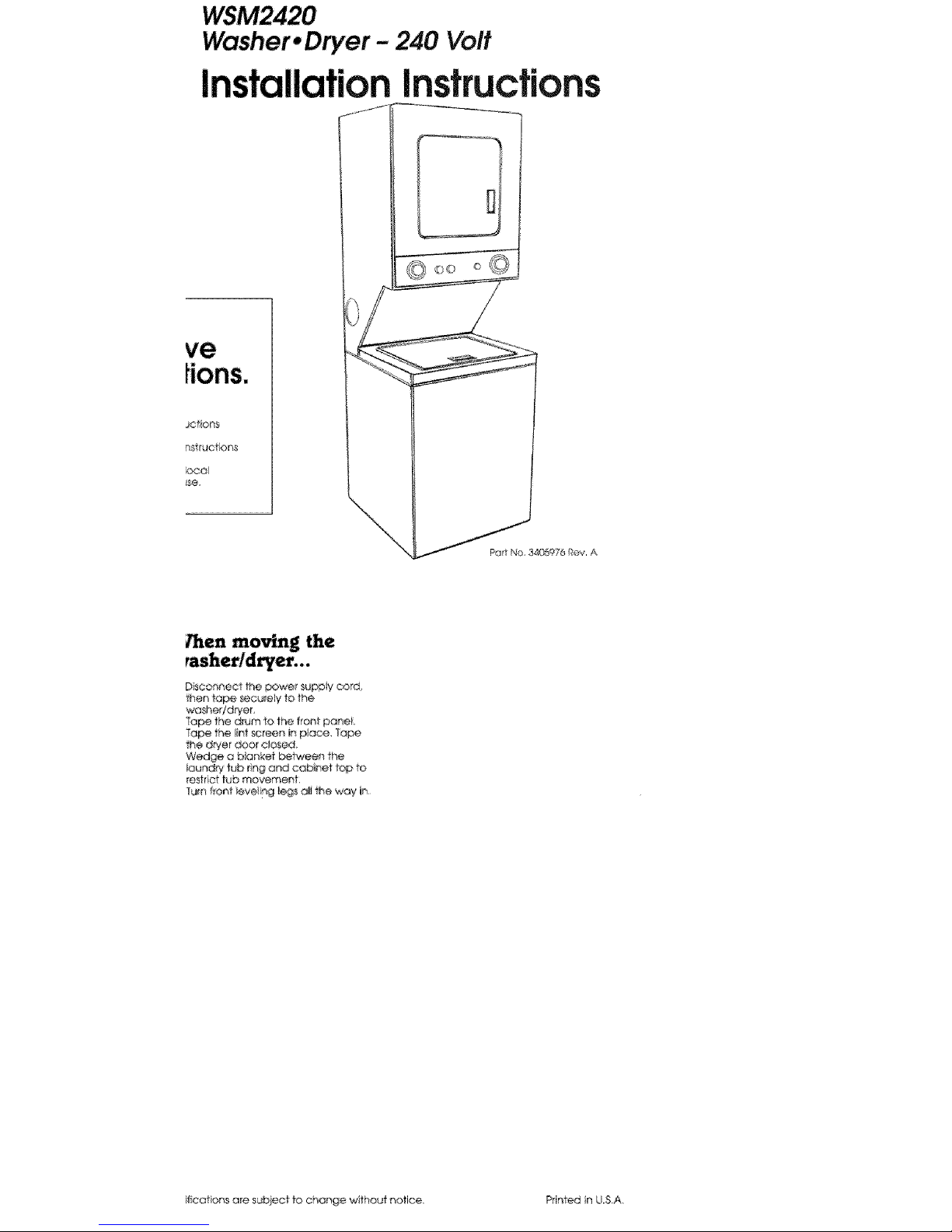
Washer* Dryer - 240 Vo#
Instructions
ve
JCt#on$
locol
\
__P_'_34GSg76 ROY A
_en moving the
D sconnec] the powe_ supDly cord_
then tape securely 10the
washer/drier
Tope the drum to the fforfl poneL
Tope the int screen in place, 1ape
the d_yer does elosed_
Wedge a blanket be_ieen the
Ioundry tub ling ar4d cabinet top to
reset ct tub movement,
Turn front leveling legs ali the way in
ifcations are subject tOchonge without notice. Printed tn U.S.A.
Page 2
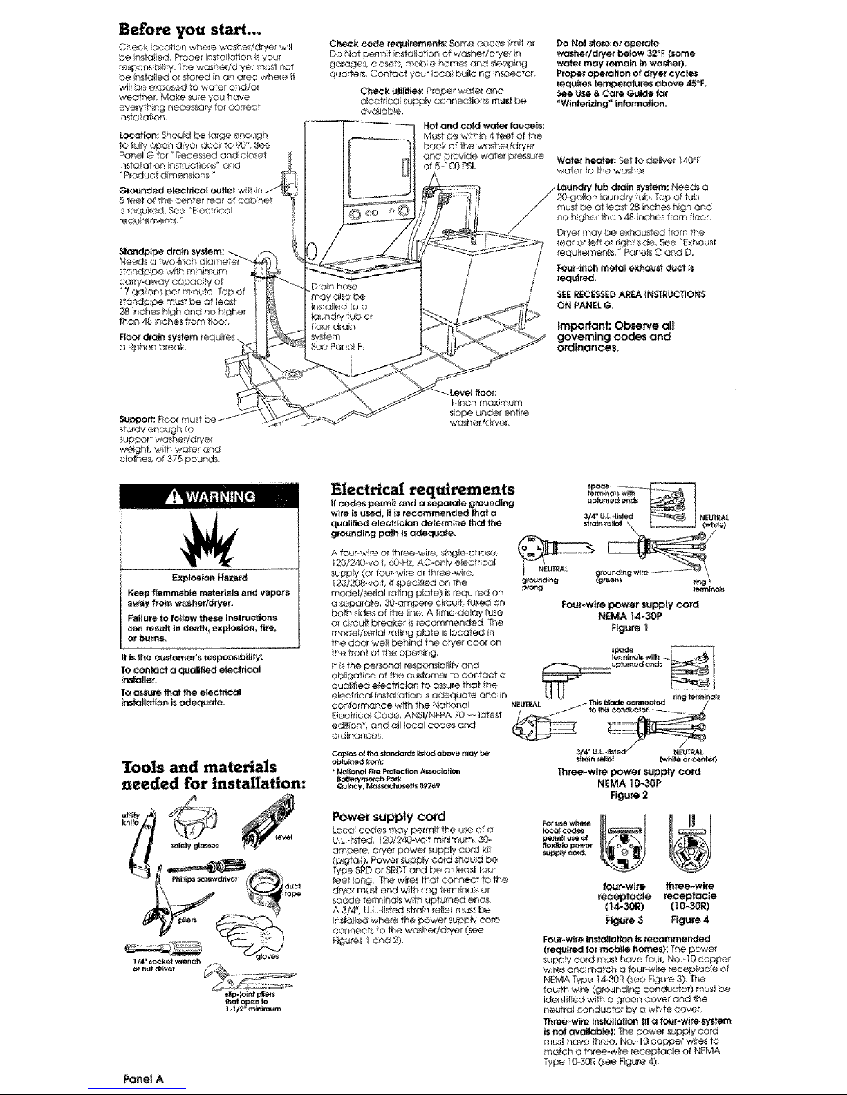
I.oeati_:Shouldbetargeenoagh
tofuhlyopendryerdoo_te_°,See
PanelGfer"Recessedandcbset
insteJtatIonnst_uefions"and
'_P_oductdimensbns,
5 feet ef the center rear of cabinet
is required, See "Electrical
requ rements _
standpipe with m nimum
carry-away cepac t¥ of
17(
standpipe must be of _east
28 Inches high and no highe_
than 48 _nches from floor,
F_or d_in
a sphon break,
Check c_ requiremetlts: 8©me codes iimit or
Do Not parrot nstaltat_an of washef/d_/e_ n
garage& closets, mobile homes end s!eeplng
quarters, Contact your _oca_building ins_eto_.
Cheek utilities; Proper water and
electrical suppIy connectiens musl be
aveilable,
Not and ¢t.._ water faucets:
MU_ _ce w_h_n 4 _et of the
back of the washer/dryer
cRd prov_t_@water p_sure
of 5 i00 PSk
Do Not siam or operale
w_sherldhler below 32_F (some
w_er may remain in washer),
Proper operation of dwer cycles
requl_es temperatures above 45_F,
See _se & Care Guide for
"Winleilzlng _ lefom_atlon.
Waler heater: _t to deliver t40_F
water to the washer,
rear or taft o I_ghf side, _e _E×haust
requ rements #Par_e_sC and D,
Fourdr'_h melal exhaust duct is
required,
SlOERECESSEDAR_A I_UCTIO_S
ON PANELG.
Important: ObseP,'e all
governing codes and
ordinances.
Supped': Floe r_ul
sturdy enough to
support washer/dryer
weight, wth water and
ebthes, af 375 pounds
Explosion Hazard
Keep flammable materials and vapors
away from w_hertdryer,
Faflure to foilew these instru_tions
can tes_lt in de_h_ explosion, fi_,
or burns,
It is the e_fome#s respondbilily
TOconlaet a qualified electrical
I_taller.
tO assure that the e_ectrical
ins_ol|atlan _ adequate,
Tools and materials
needed for installation:
sl_p-je_t p_lecs
tha_ enf_
Panel A
1-inch maximum
s_ope under entire
washer/dryer,
Electrical requirements
If codes permit and a s_arala g_edl_g
_te _ u_d_ It is r_e_meeded that o
quelifie_ electrician determine that the
grounding po_h is adequate,
A four-wire or three-wire singte,.phose,
I20/240 velt 6GoH_AC_enly e_ec_ col
supply (or four, wire Or th_eemvd_e,
120/208 volt, if spec fled on the
model/_edal rating pk_le) is requ red on
a separate_ 30.ampere ci_cu f, tided on
both s_des of the t_ne A time-delay fuse
or circuit bre_ker s reeemmeaded_ The
model/sefial toting plate is leeat_ In
the door welt behind the drye_ door on
the front ot the open ng.
t S the peL_anel respor_s_bii4y and
obliger on of the customer te contact a
qualified electrl¢_n to a_ure that the
e_ctrieat ir_staliation is adequate and n
coniormanee with the National
E@cirtcel Code, ANSI/NFPA 70 -- lat_-st
adrian * and all _oco_c_es and
ordinances,
Ceples el lhe e_r_i_ _t_ above m_y be
"Nal_l ere Pre_io_ Associate
_tte_ym_h P_
Q_ncy, _ch_Iset_s 02269
dng fe_a_
3/4°e_LoSst N_A_
Three-wire power supply co_d
NEMA _0-30P
Figure 2
Loca_cedes may' permit the u_ d a
U& dsted, 1X}/24_'_vett m nlmum 30.
ampere, dryer power supply" cord kt_
(pigtail), Power supply co_d shou_
Type SRDof SRDTand be at east fo_3r
leer _ong The w_resthe1 connect to the
dP_,ermust end w/h ling term na}s or
spade Semifinals with upturned ends,
A 3/4", U £ II_ed stron reief must be
insla/_e_Jwhere ihe power supply cord
connects 1o 1he washer/dryer (see
F_gures 1and 2),
_eex_i_e_er
four-wire three-wire
receptacle receptacle
(14-30R) (10-30R)
FIgL_ 3 Figure 4
FouPwi_e installation _ recommended
(required to_ mobile homes): The power
sup_y cosd must hove four, NO_40 copper
wires and match a fo_r wlre receptacle ot
NEMA Type 1_30R (sere Figure 3). _he
fourth wire (grounding conductor) must be
idenfifi_ w'ith a gree_ cover and the
neutral conductor by o white cover,
Three wire Ir_steilatioe (ifa four-wire system
isnet available):The power suppb/cord
must have three_ No,-10 copper wRes to
match a three-w re receptacle of N_MA
_ype 10&OR (see Fk_ure4),
Page 3
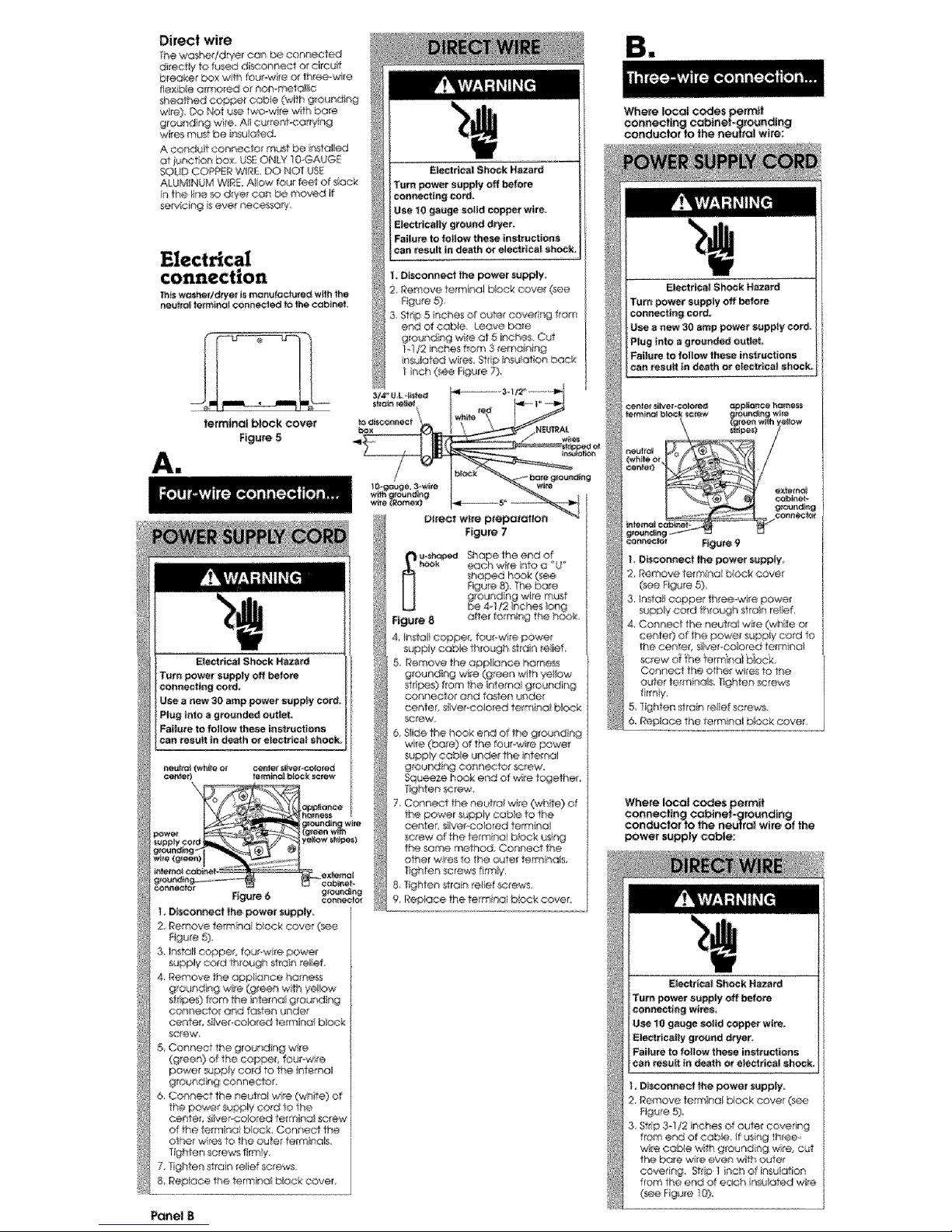
Direct wire
The washe_dryer can be eennec_d
_re_y _ fused diseoenect or circuit
bleaker box wth teu_wire er _h_ee-wlre
fie×ib4e @_nored or non-mete II¢
_#_eo_h_ eO_pet cab!e (with gronnd¾_
wre) DO Net u_ two-w re with bare
grounding wire, AI curre_t<orry ng
w_essFTruStbe ir_suo_d_
A conduit connecter re_t _ Ir,_tc_lied
at l_.notion box, USEONLY _GGAUGE
SOUD COP'PERWg_. DO NOT US_
ALUMINUM W_RE.A_IOw fou_ feei ofslack
n the I_neso dryer con be moved }t
servlcir_g iseve_' n@eessory.
_i_ wesher/d_yer is mam_ractu_ed wffh the
r_utfa| terra.at connected to the eobJnet.
tetmtnal block cover
Figure 5
Ai
Electrical 81tock Hazard
Turn power su_p_:y off before
coenectiag ¢ord_
U_e a new 30 amp power supply cercL
Pl_Jginto _ groencled s-ut_
Failure tofollow these aspect ens
can result in death or ele¢_icaI shock;
cent_ _e_ _ _tew
Figure 6 g_g
I DIscor_nect the power ,1apply=
2 Remove te_mna bbck cove _e
F@jre5),
3. Irfsto_lcoppec four w re,#owe{
supply co_d through stain _@ief
4. Remove the appliance harness
©or/Rector arid fosk:en under
Center, s_ivef*eolo_ed termina block
5, Connect the g[e nding wire
(green) of the copper, fourow re
powe_ sup__y cord to the internal
grout'cling connector,
6. Connect the neutral wits (white} of
the pewe_ supply cart to the
other wres to _heouter termhl¢_B
T_ghten screws firm}y,
7. lighten strain re}ief _rews
&Repioce the lorraine b_c_s_cover
Panel B
L Disconnect _e power supply
2, _emove terminal Dock ¢ove_ (see
Rgure 5),
3. Stdp,5 inches of oufe_ eove_ing from
en_ of cable. Leave bare
grounding wi_e at 5 troches Cut
}-}I2 i(_che_ fitom 3 ;erna_-_ing
nsu_ated wires Strip ineJIot on back
inch (_e Rgure 7),
Figure 7
[_ Shape the end 0¢
each wre eta a _'U_
Figure 8
4. e_sta_tscraper, four-wire power
suppy eatNe th_eugh strain _elief
eo_nector and f<_fenunder
wife (bare) of the fourow re powe_
suppy cab._e unde_ the ntemol
ground ng connector screw.
Squeeze hook end dwire legether,
Tighten _re'w
7 Cor_ne_t the neutral wre O_Zhite}of
the power supply cabs to the
cerlter, s@@_-colorod terrtll_'lol
screw of the termino} back using
the some method, Con_ OCtthe
ot_er wkes 10 the outer term nora,
Tghten screws firmly,
S _qghfen s ralnre_ie_screws,
9, Repk_ce the te_miri<:flbksck cover.
Be
Where local codes permit
co#netting cobtnei-gro_nc|ing
sonde€for to the neu|ral w_re:
Where local codes permit
co,nearing eobinef_gto_nding
conductor Io the neutral wire of _he
Power supply Cable:
_l_rlo_ S_h_;_:kHazard
Tern power s_ppty off before
connectir_g wires
Use tO gauge soi_ copper w_re.
_e_ricalty ground dryer.
Failure to |allow these ir_st_ectiens
can resuR in death or electrical shock.
Page 4

Figure _2
4, Install eeppe, three wire pc,wet
super,,* cabe thraugh stran relief
Slide the hook end of the neutrai
(white o_ canto 0 wre from the
three-wit÷ power suppy cable
undo the center, silv®Pco ored
term no_ screw oFthe formica! b:ock,
Squeeze the hook end oF the wire
together Tighten screw,
6 Connect the othe¢ wr_ 1o the outer
terTenas _s_ng the _me method,
i"igt len screws firmly Gee Figure !2)
7. f_ghten _tain relef screws.
love&
Where toeat codes DO NOT permit
eo_necttng the cabinef._ounding
conduclof tothe neu#al (white) wire:
4 Remove the appI_ance harness
grounding wie (green with yellow
sir pes) from the hte_d_ gro_nding
conDo©taR
5 Connect the grounding wi_e
(green wlfh yellow stripes) and the
neutral @_hto) wi_e d the power
supply cord o direct wire cable to
the center, siiver co ored terminal
ecew of the terr:nk_ei b_ock,
Connect the other wies to the
alter tem_inals. Tighten screws (see
Fgure 3).
& Connect o sepon_te copper
grounding wire (NO 0 rain mum)
See Connection details*" for
detai ed ns*ructions,
7 Tighlen s#an reief screws.
8 Replace the terraria biock cover.
F_re t4
Use g_ound r_g wre and clamp
e_embty (Ra_t NO,685463) or NO-10
gauge m_r_ihurn eopt_ g_eund ng
wre.
F{gure 15
Connect ground_ "w_re_ a
grounded cold ware pipe* wth he
e_amp and then to the extemc4
ground ng conneeIOr on the
washed!dryer (see F_gures 14and ! 5)
Do Not ground to a gas supply pipe or
hot water plpe_ Do Not connect the
power supply cord to el_ctrtcal power
supply until the washer ld_¥er is
permanently grounded,
* O_ourlded c_,_ldwater pipe must t _"_ve
meta car4 nui*y to eiectricai grc_._nd
and not be nfe rupted by plastic, tubby)
OIo!her elecff col ir_sulaN-igr;ohPectors
su_chas hoses f fling& washers or gasket_
{ino_x_i_ water meter or pump) Any
electrical ir/_Jlating connector _neuld be
jumped as shewn tr__igure 16 w*lh a
length of No-4 wte _cure y c_amped to
bare rr,e o! at beth e_ds,
_aust requirement:
Do No_ use non-met@ t@×ibJevent,
metal vent that issmolder than _ou
riches in diameter or exhaust heeds
wth magnet_ latch÷&
Do Not e×hausf draper_nto a chimney
turt-_ace cold ar duc_ attic or oraw_
spaco, or any other duct u_d for
ven_ing
DO Not }nsto i fiex b_event in enclosed
wa_ls, ce_hgs or floes
If using on existing exhaust system,
cleon lint from entire length of exhaust
sys_m. Mo_e sure exhaust hoo_l is not
plugged with tint.
The exhaust system should be inspected
and cleaned yeorly_
I_eplaee any vinyl at melailtzed p_ostte
foilexhaust vent wffh dgid meter ot
flexible metal 'vent,
U_ duct tape _o _al
at* jeints. Do Not use
screws to seeui_ vent
Four-inch dgld metal pipe is preferred
Plan installation to u_ the fewest
number of e}bows and _u_ns
Metatilextbie vent should be _uly
extended and supported when the
dr/e _sin iis final position, DO NOT KNK
OR CRUSH T4E VENL The metal flexible
vent must be fullyexten_d toallow
c_equate exhc_uetair to flew,
Allow as much room as possible when
using ebows or makng turns, Bend vent
gradually ra avoia kinkng Remove
excess flex b_e vent to avoid sagg ng
and kink ng that may resutt n reduced
air few,
Panel C
Page 5

Recessed and closet Recessed and closet
Fire Hazard
Recessed installation
(Shown withlegs extended 1i_¢h from
boffom o_washe_'/dryerJ
Exhaust dryer outside _ installed in a
e_osef
Use Exhaust Deflector Kit 594609
instatled _na recessed arse_
Failure to do so can result in death or
fire.
To prevent large amounls of !lnl and
moisture from accumulating, to
maintain drying e_iotency and to
p_event exposure !e possible health
hazards, lhB washer/dryer should be
exhausted outdoors.
This wosheddryet may be Insta_led in a
rece_d area of closet.
The hstaiiat_on spac rg tsh inches arid
s minimum ai ow_bl÷. Add tiona
spachg should L_econsideied ter ease
of _ns_aIO,%n, servichg artd camp lance
w_th Iooal codes and ordinances
Ifebset door islnslal/ed, the m h_mum
ur_ebstrueled a;r oper_Tr_gsintop and
bOttOm are requ red, Leuvered doo_s
wth equivalent oi_ open rigs are
acceptable _,,t
Other instai ofions must use the _i_imum
dii'nens ons ndicoted
fron_ view side view
Minimum insfallofion _cir_g
spO¢_g co_ b_ O inches
Closet installation
t
] front v_ew
U_ob_mc_eda_ _i_ e_e_r_r_m forCiOset
do_r L_ve_l doorwt_ eq_'_ent _ ope_gs
rear view
&
324/8 _
,I
side view
"°?iil I
be needed
side view
Panel G
Page 6

Maximum{eng_of the e£naust system
depends upoe the type at ven_ used.
number of elbows and the _ype of
exhaust hood. the maxim_Jm ength for
bolh red and flexib e vent B shown in
the ehorl
MaimEd,_
I_6 0
2 161t 5_r
_hem_×l_aurnterq_th u_ng_ _ x _ _e_tt_tlg_J_
ventwith 2e_bows_nd a2-1/_ e_ha_t hc_aa}_B_.
_or exhaust eonfigu_..cC,ions olher than
tho_ sled n the chad. the Book
pressure MUS1NO[ exceed 0.2 iehes
water c@umn at _he back of the
washer/dryer. 9_e back pressure shoud
be cheerio by a qua_ifle'a techn cian.
Ser4ee check: The bobk procure n any
e_haust system used must eat exceed
02 nches of water coumn measured
w_th er. ind ned manometer at the
po_r4 _hat the exhaust vent connects to
the dryer
L:×haosttng_he dryer eetside s
recommended Recessed nsta_l@tion
that isr_ot exhausted outside mus_ u_
_xhe,ssl Deflector Kit WE25XO220 %e
W_ecessed and dose_ nstelbfion
nstructiens." Pan@ G for ueo_ssfructed
air opening _equ}remer#s,
Iftheweshei/_eyer isinsta_iecl#ie
confined area S_eh as e bedroom,
bathroom or cleset_ it m_st be
exheested to the Outside and S_o,nsion
mist be made _orenough air tar
venti_olkxs Check governtr g codes and
ordinances AI_4_refer te ft_e 1Recessed
_nd Close_ installer on inshuctions" on
Panel G,
M exhaust hood sho_ld eo_ the
exhaus_ vent to prevent exhausteG air
from re_urnng nro dryer The curie4 o{
the hood must _ at leas112 nches
from the ground or any ob_ec_ that may
be _ the path of the
exhaust.
FoL_r-inchexhaus_
hood ispreferred.
However a 2t/2
inch exhaust !1cod
may be use@ A 2.
1i2-tnch exhaust hood c_eates greater
back pressure than other hood 1spas.
For permanent installation,a stationary
exheest system is req_ired_
Mobile home instal!_ion
This washer/dryer is s_ilable for mobile
home ins_llatiens.The Insteliatlo_of hhe
washer/dryer m_st oonfeFn to the
M_utoo{_ped _ome Constr_ctlon end
Safety, Ti|le 24 C_R, Par_3280 (formerly
the Federal Standard for Mobile Homes
Construction end Safety, Title 24, HUD
Pod 280, latest edition).
enclosed ©red, #oar encJe_ _e_
Extens on be'hand the ene!osure wl!!
pro"vent iet and me sture budup under
the mobile home,
with washer/drye_ in laundw area,
• 4 leg_ • 4 |_, ware{_
1 ar_ h_Se ¢{¢1_ hO_e W_l_
package Check that al parts were
nduded
_eveling _eg inte the hole
in the rear come_ on the
bottom of he
washeUdryen Push _eg n
untl t snaps in_o p!ace_
Do the t_ame same thhg
w_th the ether even@
_eg in the other rear corner,
tnjury Hazard
More than one person _sPeqt_ired to
lift, flit or move the washer/dryer
because of its weight sad size.
Foliate to follow this instruction may
result in injury.
Truck only from Pear to prevent prod_ct
damage.
IPLf on safety @asses and @eves.
Stes 4)
1 With one of the front
legs n hand check the
ridges for a diamond
morking_ That% how for the
leg s supposed to go nto
the hole, Staff to scow _he
legs hie the' holes in the
front comers by hand
%
Use slip-joint pliers to finsn turning the
front legs ,_r4you reach the diamond
mark
Numbers
correspond
to steps.
Slt_ washer/drye_ onto cardboard o_
_rdbeard befo_:emoving ocpe_ floor to
prevent damage to lloor oove_ng_
I Place a pace
Of cardboard or
hardboard n front of
carton, Now stand the:
washeUdryer upright
Side washeqdryer
_ p_venl p_cr
d_ge, dO n_
t_ve Com_
p_Is _r_ the
ca_O_ b_e
c_in e,
out the oadon down one comer.
Remav_ cotton,
Panel D
Page 7

1 Remove
the two _ea[comer
po_stslocated at the
back of the
washer/dryer.
Remove the two
corner pieces
attached to the lower
front of the
wosher/dryer_ Do Net
_emove the foam
s__pping paces
between the washer
and dryer until the
washef/drye_ is in pace
1 O, Move
foam shipp ng
pieces outward
iust enough to
c_ea_ the washer
tid. Untape and
open the washer
Id. The latch
under the dryer witl hold Hidopen.
cor4_
pe_
of baskeh Place hoses w_th other parts
up on latch_ Case d,
or cable to drye_ See "Electrical
connection, _ Panels B and C. Do Not
plug power supply cord into ouie or
econnect power a,_this time,
Sl_p and FaffHazard
Use new water inlet hoses.
Failure to follow this instrection
could result in he_l injury, broken
benes_ or bruises from sl_pping and
falling le weter on floor.
I _ _eupS_
end of the nlet hoses, Check that
washers are firmy seated in coup rigs,
Panel E
Numbers
correspond
to steps.
11.30.
1 61Attach hose to bottom (hot
water) !nlet valve opening first;then
second hose to tap (paid wateO n_t
valve. T_ghien coup rigs by hand. Use
pliers to make an addiiiona_ two-thirds
turn.
IMPORTANT: THIS PROCEDURE
MUST BEFOLLOWED TO ASSURE
PROPER INSTALLATION.
d_i_ hose
1 7I_O _reventthed_oinhose
from comng off at eaking_ it must
instaled per the following nsttuctiens;
1,Wet the inside end of the dron hose
w#h tap wate_ DO NOT USEANY
O_HE_ LUBRICANT,
2 _ueeze ea_ _ drain hose ciamp
wf_ piers to open and place clamp
over the end of the dran ho_.
3 _-dle ho/@r_g clamp epen_ wo_k end
of dralrl hose onto dran ceneeetor.
4. Posit on c_amp ove_ the drain ho_
area ma_ked _clamp" Release
camp, Camp _ould be 1/4 inch
from end of drain hose,
laundry |_tb dt_n system;
Open yellow clamp and
slide over "hook _end of
drain hose to secure the
l/gd and car ugated
_¢ticns togelher
Floor d_ain systemr Do
Not in,all _hook" end of dran hose to
co rugated _c:rion. Consult your
plurn_r _orproper insta lotion.
9=
SI_ woshe_/drye_ onto eo_dboerd or
hardboard before moving across floor fo
avoid damaging floorcove_Ing.
_J_
1
e_het side of the washed/dryer, move
wa_er/drye_ c_ese to final position so
you con e_ib, complete the follow ng
steps. (Go to Step 20.)
tf you ere working in a closer o_
reoet,se_ area, move theewasheridrye_
into flnai posit en ar'd rernove
cardboa_d,!hardboard from undei"
woshe_/dryen _emove the lv,,o foam
shipp#ng pieces bel'ween the wa_qe_
and dryer and place with the o.ine[
sh p_:xng pieces. Remove the two
Philt ps-head screws ocateo of the lop
of the access panel (See _lu_tret on for
Step 25) Remove access panel end set
access ;:_nel and screws aside,
Complete the fat owing steps through
the aoce% a_ea
eta aundry tub o standp pc. Check fo_
proper length of d_oln ho_e.
1 II Before altaching w_er in et
hoses. _un water 1hrough both faucets
into a bucket [_s wil_get rd o por_Jcies
In water lees that migh_ cog hoses.
Mark whic_ is the her water faucet
(inlet marked !4") to hot water faucet
/s_ach top inlet hose (inter marked 'C")
to co_d water fa _cet Tighten coupings
to the faeoefs by hard, Use p_ers lo
mr_ke final two4h rds turn.
Page 8

Move w_her/dtyer to its permanent
locallon_ Remove cardboard/hardboard
from under was,her/dryer,
wosher!d_yer into final position.
* Ti/}the washer/d_yer orward, raLqng
back legs I inch Off }he floor _ that
the rear _ttqeve/ng legs wil_ ad_us}
Gently _ower the washer!dryer to the
floor
, Check tha_ the washer/dryer _slevel
by plae ng a carpenter's eve on top
of the washer, first side to sde. then
front to back,
- It _1b not/eve!, adjust the front legs
up or down,
,-- Ti_tthe wa_ner!dryer forward,
raising back legs 1 inch Off the floo_
so that the rear _lfqeveling legs
will adjust, Gen_y lower the
washer!dryer to the floon
-- Check that the washer/dryer is
love. Repeat _ needed
CHECK THATDRAIN HOSE IS NOr _ISTED
OR KINKED AND iS SECURELYIN PLACE
plasSc _d strap
in laundry tub or standp pe Wrap the
Plast c beaded strap around }he drain
hose and aundry tub orstendp pc,
thread _aded end of strap through
keyhote end Puli until st'_op is tight, Slide
strap into narrow end of keyhoie to lock
strap n p_ace See Rgures A-B
If the wate_ intactfaucets and drain
standpipe are _eeessed, t_ghf|y wrap the
past_ beaded strap around the drain
ho_ and route1 body, (Do Not wrap
strap arour'd }he faucet tsandles or
stems) Thread b_aded end of sirap
through ke,/ho_e end Pul unJiI strap is
tight. Side st_ap nto narrow end of
keyhoie to lock s#ap in ptace, D
_e igure C,
Secure the drain hose to the tub
_ stc_rdpipe wt_ the p|a_ic
_mp Faiture to property secure
drain hose could result in water
demage,
If drain hose eatt4_et be ......
strapped _tO ....... _
place, hose most t 2 _\
be cut exactly to I :'
length so hook _ I I i J
endiS held fighW l . _ '!
over _ ot tub or I _ j _ i
star.pipe= See I I J I J
Figure D, b_*_-_r i
Note: If washeE/dryer IS moved to adjust
drain hose, the washer/dryer must be
leveled e_n Repeat Step 23. Race
cardboard under lhe washer/d_er al_
care_}ly move washer/dryer to avoid
_mag_ng _r covering.
access p_ne i_ Step g; remove tt_e
1we foam sh pping pieces between the
wa¢*_e_and drye_ ar!_ place wilh the
ether shipping pieces. !fthe exhaust
duct cannot be connected from the
s_deof the washer/dryer the exhaust
duct can be reached from the #ant
through the access panel, Remove the
l_vo _hltiips-heod screws located at the
top of the access panel Set acce_
paneq and screws a_de.
exhaust vent that is need_ to connect
the dryer _o the exhaust ho_ (See
_Exhaus} requ fomentS. '_Pcne_s C and D.)
,_._sher/dryer and then }o the exhaust
hood.
, Use the _raightesr path posebie to
avoid 90 ° turns.
• U_ duct tape to seal a_ }ants in the
exhaus_ system
• Use eauiking compeund te s(_sl
exter o_ woli open ng areund e×houst
bead,
REQ_I_M_NTS 8E SUREYOU HAVE
CORRECT E_CT_1CAL SUPPLYAND
RECOMMENDED G_O_NIDING METHOD.
Check the instal!arian _n_uctions _ see
that you hove competed each step
Complete any missed steps before you
cent_nue_
9 ISChech that a_ pa#s ere now
nstal e(:L _e pa_ Ist. Pane_ D, If there b
an extra part go back through steps to
see which step was skipped.
Numbers
co_resportd
to steps.
removed alt the shipp ng pieces,
ncludlng the round _fipp n4;_piece,
D_spose of all moter}aB in proper
n_aRne(
if you do net remove the round shlp_ng
piece_ your wosherldryer may "work"
away from its location,
t lCheck that you have a_lof
your tools
check for _eake T_ghten couplings if
there is _eaking_ Do Not ovedighten; ff'_is
coud cause damage to faucets,
sure to tighten screws at each end of
the access pa_eL
{_.YL_ to fuly understand "your new
washer/dryer Open dryer door, Check
to be sure lint sereen is in its p_per
positioA. Wipe out drum,
grounded outlet, Reconnect the _._ower
suppay. Now start _e washer and allow
it to complete the regular cycle,
6 n Start dryer and allow It to
comp_te a ful heat cycle to make sure
;t iswe_ng properly
Yell hove seceess_lly inste|lea_your
new washer/dryer_ TOget the most
efficient llse from your new
washer/dryer, read yau_ _s_L_.,_r._
Keep Installation |nstpJattees and
Guide,
15.
22.
Panel F ......
 Loading...