

Page 1
GE Digital Energy
Multilin
Motor Protection System
339
Motor protection and control
339 revision: 1.40
Manual P/N: 1601-9103-A3
GE publication code: GEK-113562B
Copyright © 2010 GE Multilin
GE Multilin
215 Anderson Avenue, Markham, Ontario
Canada L6E 1B3
Tel: (905) 294-6222 Fax: (905) 201-2098
Internet: http://www.GEmultilin.com
*1601-9103-A3*
Instruction manual
GE Multilin's Quality
Management System is
registered to ISO9001:2000
QMI # 005094
Page 2

© 2010 GE Multilin Incorporated. All rights reserved.
GE Multilin 339 Motor Protection System instruction manual for revision 1.40.
339 Motor Protection System, EnerVista, EnerVista Launchpad, and EnerVista SR3 Setup
are registered trademarks of GE Multilin Inc.
The contents of this manual are the property of GE Multilin Inc. This documentation is
furnished on license and may not be reproduced in whole or in part without the permission
of GE Multilin. The content of this manual is for informational use only and is subject to
change without notice.
Part number: 1601-9103-A3 (September 2010)
Page 3

Table of Contents
1.INTRODUCTION Overview ................................................................................................................................1 - 1
Cautions and warnings ...................................................................................................1 - 2
Description of the 339 Motor Protection System................................................1 - 3
339 order codes..................................................................................................................1 - 6
Specifications.......................................................................................................................1 - 7
Password security....................................................................................................................1 - 7
Protection.....................................................................................................................................1 - 7
Metering........................................................................................................................................1 - 10
Data capture ..............................................................................................................................1 - 11
Control...........................................................................................................................................1 - 12
Inputs .............................................................................................................................................1 - 13
Outputs..........................................................................................................................................1 - 14
Power supply..............................................................................................................................1 - 14
Communications ......................................................................................................................1 - 15
Testing and certification .......................................................................................................1 - 15
Physical .........................................................................................................................................1 - 16
Environmental............................................................................................................................1 - 16
2.INSTALLATION Mechanical installation ...................................................................................................2 - 1
Dimensions..................................................................................................................................2 - 2
Product identification .............................................................................................................2 - 2
Mounting ......................................................................................................................................2 - 3
Unit withdrawal and insertion............................................................................................2 - 7
Electrical installation ........................................................................................................2 - 8
339 terminal identification...................................................................................................2 - 9
RMIO module installation......................................................................................................2 - 11
Phase sequence and transformer polarity...................................................................2 - 13
Phase current inputs...............................................................................................................2 - 13
Ground and CBCT inputs.......................................................................................................2 - 13
Zero sequence CBCT installation ......................................................................................2 - 14
Voltage inputs............................................................................................................................2 - 15
Control power ............................................................................................................................2 - 15
Contact inputs ...........................................................................................................................2 - 16
Trip and Close output relays ...............................................................................................2 - 16
Serial communications ..........................................................................................................2 - 19
IRIG-B .............................................................................................................................................2 - 20
3.INTERFACES Front control panel interface........................................................................................3 - 2
Software setup....................................................................................................................3 - 10
339C MOTOR PROTECTION SYSTEM – INSTRUCTION MANUAL TOC–1
Description ..................................................................................................................................3 - 2
Display ...........................................................................................................................................3 - 3
Working with the Keypad....................................................................................................3 - 3
LED status indicators..............................................................................................................3 - 4
Relay messages ........................................................................................................................3 - 6
Default message.....................................................................................................................3 - 6
Target messages.....................................................................................................................3 - 6
Self-test errors..........................................................................................................................3 - 7
Flash messages.......................................................................................................................3 - 9
Quick setup - Software interface ......................................................................................3 - 10
EnerVista SR3 Setup Software............................................................................................3 - 10
Page 4

Hardware and software requirements.........................................................................3 - 11
Installing the EnerVista SR3 Setup software..............................................................3 - 11
Connecting EnerVista SR3 Setup to the relay ............................................................ 3 - 14
Configuring serial communications...............................................................................3 - 14
Using the Quick Connect feature....................................................................................3 - 15
Configuring Ethernet communications........................................................................3 - 16
Connecting to the relay........................................................................................................3 - 17
Working with setpoints and setpoint files .................................................................... 3 - 18
Engaging a device..................................................................................................................3 - 18
Entering setpoints...................................................................................................................3 - 18
File support ................................................................................................................................3 - 20
Using setpoints files...............................................................................................................3 - 20
Downloading and saving setpoints files......................................................................3 - 20
Adding setpoints files to the environment..................................................................3 - 20
Creating a new setpoint file...............................................................................................3 - 21
Upgrading setpoint files to a new revision .................................................................3 - 22
Printing setpoints and actual values.............................................................................3 - 23
Printing actual values from a connected device.....................................................3 - 24
Loading setpoints from a file.............................................................................................3 - 25
Upgrading relay firmware ................................................................................................... 3 - 25
Loading new relay firmware..............................................................................................3 - 25
Advanced EnerVista SR3 Setup features ......................................................................3 - 27
Data logger................................................................................................................................3 - 27
Motor start data logger........................................................................................................3 - 28
Transient recorder (Waveform capture).......................................................................3 - 30
Protection summary..............................................................................................................3 - 33
Password security ..................................................................................................................3 - 34
4.ACTUAL VALUES Actual values overview ...................................................................................................4 - 1
A1 Status................................................................................................................................4 - 3
Motor status ...............................................................................................................................4 - 4
Clock............................................................................................................................................... 4 - 6
Contact inputs ...........................................................................................................................4 - 6
Output relays ............................................................................................................................. 4 - 6
Output relays - Breaker........................................................................................................4 - 6
Output relays - Contactor...................................................................................................4 - 7
Logic elements ..........................................................................................................................4 - 7
Virtual inputs ..............................................................................................................................4 - 7
Remote inputs ...........................................................................................................................4 - 7
Remote outputs ........................................................................................................................ 4 - 8
Contact inputs summary...................................................................................................... 4 - 8
Output relays summary........................................................................................................4 - 8
Logic elements summary..................................................................................................... 4 - 8
GOOSE status............................................................................................................................. 4 - 9
GOOSE HDR status .................................................................................................................. 4 - 9
RTD temp summary................................................................................................................4 - 9
A2 Metering ..........................................................................................................................4 - 10
Current..........................................................................................................................................4 - 10
Voltage.......................................................................................................................................... 4 - 11
Power............................................................................................................................................. 4 - 11
Energy ........................................................................................................................................... 4 - 12
RTD temperature......................................................................................................................4 - 12
Clear energy ...............................................................................................................................4 - 12
A3 Records............................................................................................................................4 - 13
Datalogger ..................................................................................................................................4 - 13
Motor start data logger.........................................................................................................4 - 13
TOC–2 339C MOTOR PROTECTION SYSTEM – INSTRUCTION MANUAL
Page 5

Event records .............................................................................................................................4 - 13
Transient records .....................................................................................................................4 - 30
Learned data..............................................................................................................................4 - 30
Learned data recorder...........................................................................................................4 - 32
Clear learned data ...................................................................................................................4 - 32
Clear transient record ............................................................................................................4 - 32
Clear event record ...................................................................................................................4 - 32
A4 Target messages.........................................................................................................4 - 33
5.QUICK SETUP -
Quick Setup settings.........................................................................................................5 - 3
FRONT CONTROL
PANEL
6.SETPOINTS Setpoints ................................................................................................................................6 - 1
Setpoint entry methods.........................................................................................................6 - 2
Common setpoints ..................................................................................................................6 - 3
Logic diagrams..........................................................................................................................6 - 3
Settings text abbreviations..................................................................................................6 - 4
S1 Relay setup .....................................................................................................................6 - 6
Clock...............................................................................................................................................6 - 7
Password security....................................................................................................................6 - 9
Access passwords..................................................................................................................6 - 10
Communications ......................................................................................................................6 - 12
RS485 interface .......................................................................................................................6 - 13
Ethernet.......................................................................................................................................6 - 13
Modbus........................................................................................................................................6 - 14
IEC60870-5-103 serial communication settings .....................................................6 - 15
IEC60870-5-104 protocol....................................................................................................6 - 29
DNP communication.............................................................................................................6 - 30
IEC 61850 GOOSE configuration......................................................................................6 - 43
Event recorder ...........................................................................................................................6 - 44
Transient recorder ...................................................................................................................6 - 45
Datalogger...................................................................................................................................6 - 47
Front panel ..................................................................................................................................6 - 47
Installation...................................................................................................................................6 - 48
Preset statistics .........................................................................................................................6 - 49
S2 System Setup.................................................................................................................6 - 50
Current sensing.........................................................................................................................6 - 50
Voltage sensing.........................................................................................................................6 - 52
Power system.............................................................................................................................6 - 53
Motor..............................................................................................................................................6 - 53
Switching device.......................................................................................................................6 - 54
S3 Protection........................................................................................................................6 - 55
Thermal Model...........................................................................................................................6 - 58
Total Capacity Used register (TCU) .................................................................................6 - 58
Start protection........................................................................................................................6 - 59
Thermal overload curves ....................................................................................................6 - 59
Thermal protection setpoints............................................................................................6 - 67
Short circuit.................................................................................................................................6 - 72
Mechanical Jam........................................................................................................................6 - 75
Undercurrent..............................................................................................................................6 - 78
Current unbalance...................................................................................................................6 - 81
Load increase alarm ...............................................................................................................6 - 84
Ground fault................................................................................................................................6 - 85
339C MOTOR PROTECTION SYSTEM – INSTRUCTION MANUAL TOC–3
Page 6

Neutral instantaneous overcurrent.................................................................................6 - 88
Phase undervoltage................................................................................................................6 - 90
Phase overvoltage...................................................................................................................6 - 93
Underfrequency........................................................................................................................6 - 96
Overfrequency...........................................................................................................................6 - 99
Underpower................................................................................................................................6 - 102
Negative sequence overvoltage.......................................................................................6 - 105
Phase reversal........................................................................................................................... 6 - 107
VT fuse fail ...................................................................................................................................6 - 107
Acceleration protection ........................................................................................................ 6 - 108
RTD protection...........................................................................................................................6 - 110
Two-speed motor ....................................................................................................................6 - 116
Two-speed motor setup ......................................................................................................6 - 117
High speed thermal protection........................................................................................6 - 118
High speed short circuit settings.....................................................................................6 - 118
High speed acceleration......................................................................................................6 - 121
High speed undercurrent....................................................................................................6 - 121
S4 Control..............................................................................................................................6 - 124
Virtual inputs ..............................................................................................................................6 - 125
Logic elements ..........................................................................................................................6 - 126
Breaker failure / Welded contactor.................................................................................6 - 142
Start inhibit..................................................................................................................................6 - 145
Emergency restart...................................................................................................................6 - 148
Lockout reset .............................................................................................................................6 - 148
Reset .............................................................................................................................................. 6 - 148
Breaker control ......................................................................................................................... 6 - 148
S5 Inputs/Outputs .............................................................................................................6 - 150
Contact inputs ...........................................................................................................................6 - 151
Output relays .............................................................................................................................6 - 152
Output Relays - Breaker.......................................................................................................6 - 153
Output Relays - Contactor..................................................................................................6 - 161
Virtual inputs ..............................................................................................................................6 - 164
7.MAINTENANCE M1 Relay information.......................................................................................................7 - 4
M2 Motor maintenance ..................................................................................................7 - 6
M3 Breaker maintenance ..............................................................................................7 - 7
Trip coil.......................................................................................................................................... 7 - 7
Close coil ......................................................................................................................................7 - 10
Breaker trip counter................................................................................................................7 - 13
Reset counters ..........................................................................................................................7 - 15
M4 Breaker monitor..........................................................................................................7 - 16
M5 Relay maintenance ...................................................................................................7 - 17
Ambient temperature ............................................................................................................ 7 - 17
M6 Factory service............................................................................................................7 - 20
APPENDIX Change notes ...................................................................................................................Appendix - 1
Manual Revision history.................................................................................................... Appendix - 1
TOC–4 339C MOTOR PROTECTION SYSTEM – INSTRUCTION MANUAL
Page 7

Digital Energy
Multilin
339 Motor Protection System
Chapter 1: Introduction
Introduction
Overview
The 339 Motor Protection System is a microprocessor based relay providing suitable
protection of medium voltage motors. The small footprint and the withdrawable option
make the relay ideal for panel mounting on either new or retrofit installations. The
combination of proven hardware, a variety of protection and control features, and
communications, makes the relay ideal for total motor protection and control. Equipped
with serial (RS485), USB, and Ethernet ports, and a wide selection of protocols such as
Modbus, DNP3.0, IEC 60870-5-103, 60870-5-104, GOOSE, the relay is the best-in-class for
MCCs, SCADA and inter-relay communications. The relay provides excellent transparency
with respect to power system conditions and events, through its four-line 20-character
display, as well as the EnerVista SR3 Setup program. Conveniently located LEDs provide
indication of overall relay operation, as well as alarm, pickup, and motor status.
The relay provides the following key benefits:
• Withdrawable small footprint – saves on rewiring and space.
• Fast setup (Quick Setup) menu provided, to guide users through a wide range of motor
• Large four-line LCD display, LEDs, and an easy-to-navigate keypad.
• Multiple communication protocols for simultaneous access when integrated into
management applications.
monitoring and control systems.
339 MOTOR PROTECTION SYSTEM – INSTRUCTION MANUAL 1–1
Page 8

CAUTIONS AND WARNINGS CHAPTER 1: INTRODUCTION
NOTE
CAUTION
DANGER
Cautions and warnings
Before attempting to install or use this device, it is imperative that all caution and danger
indicators in this manual are reviewed to help prevent personal injury, equipment damage,
or downtime. The following icons are used to indicate notes, cautions, and dangers.
Figure 1: Note icons used in the documentation
The standard note icon emphasizes a specific point or indicates minor problems that may
occur if instructions are not properly followed.
The caution icon indicates that possible damage to equipment or data may occur if
instructions are not properly followed.
The danger icon provides users with a warning about the possibility of serious or fatal
injury to themselves or others.
1–2 339 MOTOR PROTECTION SYSTEM – INSTRUCTION MANUAL
Page 9

CHAPTER 1: INTRODUCTION DESCRIPTION OF THE 339 MOTOR PROTECTION SYSTEM
Description of the 339 Motor Protection System
CPU
Relay functions are controlled by two processors: a Freescale MPC5554 32-bit
microprocessor measures all analog signals and digital inputs and controls all output
relays; a Freescale MPC520B 32-bit microprocessor controls all the Ethernet
communication protocols.
Analog Input Waveform Capture
Magnetic transformers are used to scale-down the incoming analog signals from the
source instrument transformers. The analog signals are then passed through a 960 Hz low
pass anti-aliasing filter. All signals are then simultaneously captured by sample and hold
buffers to ensure there are no phase shifts. The signals are converted to digital values by a
12-bit A/D converter before finally being passed on to the CPU for analysis.
Both current and voltage are sampled thirty-two times per power frequency cycle. These
‘raw’ samples are scaled in software, then placed into the waveform capture buffer, thus
emulating a fault recorder. The waveforms can be retrieved from the relay via the EnerVista
SR3 Setup software for display and diagnostics.
Frequency
Frequency measurement is accomplished by measuring the time between zero crossings
of the Bus VT phase A voltage . The signals are passed through a low pass filter to prevent
false zero crossings. Sampling is synchronized to the Va-x voltage zero crossing which
results in better co-ordination for multiple relays on the same bus.
Phasors, Transients, and Harmonics
Current waveforms are processed twice every cycle with a DC Offset Filter and a Discrete
Fourier Transform (DFT). The resulting phasors have fault current transients and all
harmonics removed. This results in a motor that is extremely secure and reliable; one that
will not overreach.
Processing of AC Current Inputs
The DC Offset Filter is an infinite impulse response (IIR) digital filter, which removes the DC
component from the asymmetrical current present at the moment a fault occurs. This is
done for all current signals used for overcurrent protection; voltage signals bypass the DC
Offset Filter. This filter ensures no overreach of the overcurrent protection.
The Discrete Fourier Transform (DFT) uses exactly one sample cycle to calculate a phasor
quantity which represents the signal at the fundamental frequency; all harmonic
components are removed. All subsequent calculations (e.g. RMS, power, etc.) are based
upon the current and voltage phasors, such that the resulting values have no harmonic
components.
Protection Elements
All protection elements are processed twice every cycle to determine if a pickup has
occurred or a timer has expired. The protection elements use RMS current/voltage, based
on the magnitude of the phasor. Hence, protection is impervious to both harmonics and DC
transients.
339 MOTOR PROTECTION SYSTEM – INSTRUCTION MANUAL 1–3
Page 10
DESCRIPTION OF THE 339 MOTOR PROTECTION SYSTEM CHAPTER 1: INTRODUCTION
896814.CDR
52
37
46
49
50P
50BF
50G
49
MOTOR
LOAD
Stator RTDs
Bearing RTDs
Phase CT 3
Ground CT 1
BUS
339
MOTOR PROTECTION SYSTEM
Ambient air
RTD
38
Optional Remote RTD
51
86
START
50N
TRIP
CLOSE
START INHIBIT
27P 59P
47
59_2
81O 81U
59_2
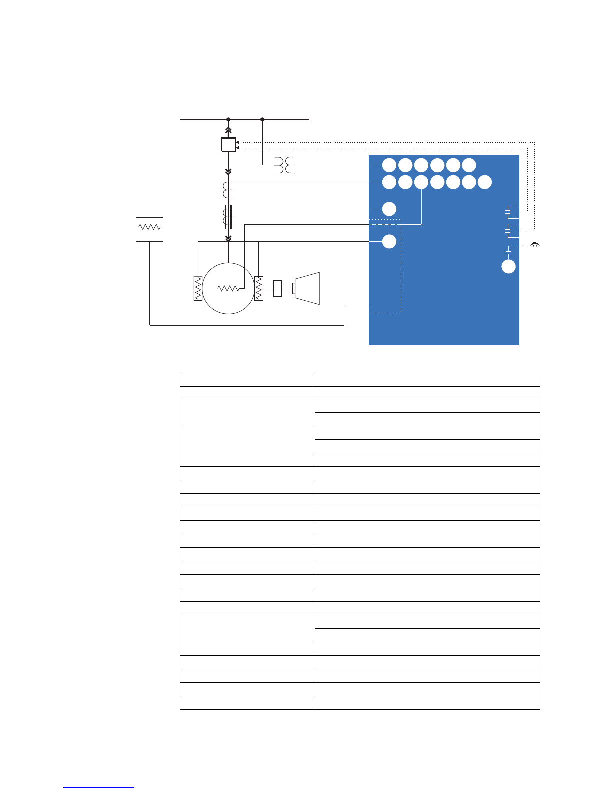
Figure 2: Line Diagram
Table 1: Protection functions
ANSI device Description
27P Phase UV
37 Undercurrent
Underpower
38 Bearing RTD
Stator/Ambient/Other
RTD Trouble Alarm
46 Current Unbalance
47 Voltage Phase Reversal
48 Acceleration Time
49 Thermal Protection/Stall Protection
50BF Breaker Failure / Welded Contactor
50G Ground Fault
50P Short Circuit
51P Mechanical Jam
50N Neutral Instantaneous Overcurrent
59_2 Negative Sequence OV
59P Phase OV
66 Starts per Hour & Time Between Starts
81O Overfrequency
81U Underfrequency
86 Lockout
VTFF VT Fuse Failure
Restart Block
Thermal Inhibit
1–4 339 MOTOR PROTECTION SYSTEM – INSTRUCTION MANUAL
Page 11
CHAPTER 1: INTRODUCTION DESCRIPTION OF THE 339 MOTOR PROTECTION SYSTEM
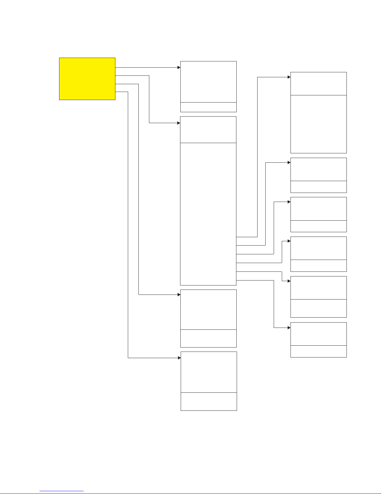
ACTUAL VALUES
QUICK SETUP
SETPOINTS
MAINTENANCE
ACTUAL VALUES
A1 STATUS
A2 METERING
A3 RECORDS
A4 TARGET MESSAGES
▼
QUICK SETUP
RELAY STATUS
NOMINAL FREQUENCY
GROUND CT TYPE
VT CONNECTION
VT SECONDARY
VT RATIO
MOTOR FLA
THERMAL O/L FUNC
S/C FUNC
MECH JAM FUNC
U/CURR TRIP FUNC
GND TRIP FUNC
PH UV FUNC
PHASE CT PRIMARY
SWITCHING DEVICE
52a CONTACT
52b CONTACT
▼
SETPOINTS
S1 RELAY SETUP
S2 SYSTEM SETUP
S3 PROTECTION
S4 CONTROLS
S5 INPUTS/OUTPUTS
▼
MAINTENANCE
M1 RELAY INFO
M2 MOTOR MAINTEN
M3 BKR MAINTENANCE
M4 BKR MONITOR
M6 FACTORY SERVICE
▼
896756.cdr
THERMAL PROTECTION
START PROTECTION
SAFE STALL T COLD
THERMAL O/L PKP
UNBALANCE K FACTOR
COOL TIME RUNNING
COOL TIME STOPPED
HOT/COLD RATIO
LOCKED ROTOR CURR
▼
SHORT CIRCUIT
S/C PKP
S/C DELAY
▼
MECHANICAL JAM
MECH JAM PKP
MECH JAM DELAY
▼
UNDERCURRENT
U/CURR TRIP PKP
UCURR TRIP DELAY
▼
GROUND FAULT
GND TRIP PKP
GND TRIP ON RUN
GND TRIP ON START
▼
PHASE UV
PH UV PKP
PH UV DELAY
▼
Figure 3: Main Menu structure
339 MOTOR PROTECTION SYSTEM – INSTRUCTION MANUAL 1–5
Page 12

339 ORDER CODES CHAPTER 1: INTRODUCTION
339 order codes
The information to specify a 339 relay is provided in the following order code table.
Figure 4: Order Codes
1–6 339 MOTOR PROTECTION SYSTEM – INSTRUCTION MANUAL
Page 13

CHAPTER 1: INTRODUCTION SPECIFICATIONS
NOTE
Specifications
NOTE:
Specifications are subject to change without notice.
Password security
PASSWORD SECURITY
Master Reset Password: ..................................8 to 10 alpha-numeric characters
Settings Password:.............................................3 to 10 alpha-numeric characters for local and remote
access
Control Password:...............................................3 to 10 alpha-numeric characters for local and remote
access
Protection
NEUTRAL INSTANTANEOUS OVERCURRENT
Pickup Level:..........................................................0.05 to 20 x CT in steps of 0.01 x CT
Dropout Level: ......................................................96 to 99% of Pickup @ I > 1 x CT
Pickup - 0.02 x CT @ I <1 x CT
Time Delay: ............................................................0.00 to 300.00 sec in steps of 0.01
Operate Time:.......................................................<30 ms @ 60Hz (I > 2.0 x PKP), 0 ms time delay
<35 ms @ 50Hz (I > 2.0 x PKP), 0 ms time delay
Timer Accuracy:...................................................0 to 1 cycle
Level Accuracy:....................................................per CT input
Elements: ................................................................Trip or Alarm
NEUTRAL DIRECTIONAL OVERCURRENT
Directionality:........................................................Co-existing forward and reverse
Polarizing: ...............................................................Voltage, Current, Dual
Voltage can be:
- Calculated from VT phases (VTs must be connected in
"Wye")
- Measured by Vaux input (3V
delta connection)
Polarizing Voltage:..............................................-V
Polarizing Current:..............................................I
MTA:...........................................................................From 0o to 359o in steps of 1
Angle Accuracy:...................................................±2
Operation Delay: .................................................20 to 30 ms
0
G
o
UNDERCURRENT
Pickup Level:..........................................................0.1 to 0.95 x FLA in steps of 0.01 x FLA
Dropout Level: ......................................................101 to 104% of Pickup
Time Delay: ............................................................1.00 to 60.00 s in steps of 0.01 s
Block from Start:..................................................0 to 600 s in steps of 1 s
Pickup Accuracy:.................................................as per phase current inputs
Timing Accuracy:................................................± 0.5 s or ± 0.5% of total time
Elements: ................................................................Trip and Alarm
provided by an external open
0
o
339 MOTOR PROTECTION SYSTEM – INSTRUCTION MANUAL 1–7
Page 14
SPECIFICATIONS CHAPTER 1: INTRODUCTION
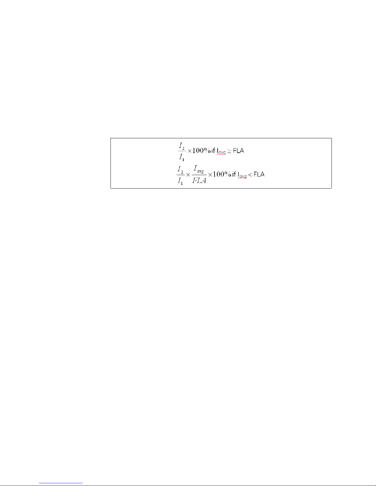
CURRENT UNBALANCE
Unbalance: ............................................................See table below
Unbalance Pickup Level: .................................4 to 40% in steps of 1%
Unbalance Time Delay:....................................1.00 to 60.00 s in steps of 0.01 s
Single Phasing Pickup Level: .........................unbalance level > 40% or when I
any phase is less than the cutoff current
Single Phasing Time Delay:............................2 sec
Dropout Level:......................................................96 to 99% of pickup
Pickup Accuracy:................................................. ±2%
Timing Accuracy:................................................ ±0.5 s or ± 0.5% of total time
Unbalance Elements:........................................Trip and Alarm
Single Phasing Elements:................................Trip
≥25%FLA and current in
avg
Table 2: Current Unbalance equations
RTD
Pickup:...................................................................... 1 to 250oC in steps of 1oC
Pickup Hysteresis:............................................... 2
Time Delay:............................................................ 3 sec
Elements:................................................................Trip and Alarm
o
C
RTD TROUBLE ALARM
RTD Trouble Alarm: ............................................ <-50oC or >250oC
LOAD INCREASE ALARM
Pickup Level: .........................................................50 to 150%FLA in steps of 1%FLA
Dropout Level:......................................................96 to 99% of Pickup
Alarm Time Delay:.............................................. 1.00 to 60.00 s in steps of 0.01 s
Pickup Accuracy:................................................. as per phase current inputs
Timing Accuracy:................................................ ±0.5 s or ±0.5% of total time
SHORT CIRCUIT
Pickup Level: .........................................................1.00 to 20.00 x CT in steps of 0.01 x CT
Dropout Level:......................................................96 to 99% of Pickup @ I > 1 x CT
Pickup - 0.02 x CT @ I < 1 x CT
Alarm Time Delay:.............................................. 0.00 to 60.00 s in steps of 0.01 s
Pickup Accuracy:................................................. as per phase current inputs
Operate Time: ...................................................... <30 ms @ 60Hz (I > 2.0 x PKP), 0 ms time delay
<35 ms @ 50Hz (I > 2.0 x PKP), 0 ms time delay
Timer Accuracy:..................................................0 to 1 cycle
Elements:................................................................Trip or Alarm
MECHANICAL JAM TRIP
Pickup Level: .........................................................1.01 to 4.50 x FLA in steps of 0.01 x FLA, blocked from start
Dropout Level:......................................................96 to 99% of Pickup
Trip Time Delay:...................................................0.10 to 30.00 s in steps of 0.01 s
Pickup Accuracy:................................................. as per phase current inputs
Timing Accuracy:................................................ ±0.5 s or ±0.5% of total time
1–8 339 MOTOR PROTECTION SYSTEM – INSTRUCTION MANUAL
Page 15

CHAPTER 1: INTRODUCTION SPECIFICATIONS
GROUND FAULT
Pickup Level:..........................................................0.03 to 1.00 x CT in steps of 0.01 x CT
0.50 to 15.00 A in steps of 0.01 A (CBCT)
Dropout Level: ......................................................Pickup - 0.02 x CT
96 to 99% of Pickup (CBCT)
Alarm Time Delay on Run:..............................0.00 to 60.00 s in steps of 0.01 s
Alarm Time Delay on Start:............................0.00 to 60.00 s in steps of 0.01 s
Trip Time Delay on Run:...................................0.00 to 5.00 s in steps of 0.01 s
Trip Time Delay on Start:.................................0.00 to 10.00 s in steps of 0.01 s
Pickup Accuracy:.................................................as per ground current inputs
Operate Time:.......................................................<30 ms @ 60Hz (I > 2.0 x PKP), 0 ms time delay
<35 ms @ 50Hz (I > 2.0 x PKP), 0 ms time delay
Timing Accuracy:................................................0 to 1 cycle
Elements: ................................................................Trip and Alarm
THERMAL PROTECTION
Locked Rotor Current:.......................................2.0 to 11.0 x FLA in steps of 0.1 x FLA
Safe Stall Time:.....................................................1.0 to 600.0 s in steps of 0.1 s
Curve Multiplier:...................................................1 to 15 in steps of 1
Pickup Level:..........................................................1.01 to 1.25 x FLA in steps of 0.01 x FLA
Curve Biasing:.......................................................Phase unbalance
Hot/cold biasing
Stator RTD biasing
Exponential Running and Stopped Cooling Rates
TCU Update Rate: ...............................................3 cycles
Pickup Accuracy:.................................................per phase current inputs
Timing Accuracy:................................................±200 ms or ±2% of total time
Elements: ................................................................Trip and Alarm
PHASE/AUXILIARY UNDERVOLTAGE
Minimum Voltage:...............................................Programmable from 0.00 to 1.25 x VT in steps of 0.01
Pickup Level:..........................................................0.00 to 1.25 x VT in steps of 0.01
Dropout Level: ......................................................101 to 104% of pickup
Curve: .......................................................................Definite Time, Inverse Time
Time Delay: ............................................................0.1 to 600.0 s in steps of 0.1
Operate Time:.......................................................T ime delay ±30 ms @ 60 Hz (V < 0.85 x PKP)
Time delay ±40 ms @ 50 Hz (V < 0.85 x PKP)
Time Delay Accuracy:.......................................±3% of expected time, or 1 cycle, whichever is greater
Level Accuracy:....................................................Per voltage input
UNDERPOWER
Pickup Level:..........................................................1 to 100% Hz MNR 1%
Dropout Level: ......................................................101% to 104% of Pickup
Time Delay: ............................................................1.0 to 60.0 s in steps of 0.1
Pickup Accuracy:.................................................as per power monitoring specification
Timing Accuracy:................................................±0.5 s or ±0.5% of total time
Elements: ................................................................Trip and Alarm
NEGATIVE SEQUENCE/PHASE OVERVOLTAGE
Pickup Level:..........................................................0.00 to 1.25 x VT in steps of 0.01
Dropout Level: ......................................................96 to 99% of pickup
Time Delay: ............................................................0.1 to 600.0 s in steps of 0.1
Operate Time:.......................................................T ime delay ±30 ms @ 60 Hz (V < 0.85 x PKP)
Time delay ±40 ms @ 50 Hz (V < 0.85 x PKP)
Timing Accuracy:................................................±0.5 s or ±0.3% of total time
Level Accuracy:....................................................Per voltage input
339 MOTOR PROTECTION SYSTEM – INSTRUCTION MANUAL 1–9
Page 16

SPECIFICATIONS CHAPTER 1: INTRODUCTION
NOTE
PHASE REVERSAL
Configuration: ......................................................ABC or ACB phase rotation
Time Delay:............................................................ 100 ms
Timing Accuracy:................................................ ±0.5 s
Elements:................................................................Trip or Alarm
UNDERFREQUENCY
Minimum Voltage: .............................................. 0.00 to 1.25 x VT in steps of 0.01
Pickup Level: .........................................................40.00 to 70.00 Hz in steps of 0.01
Dropout Level:......................................................Pickup +0.03 Hz
Time Delay:............................................................ 0.1 to 600.0 s in steps of 0.1
Timing Accuracy:................................................ ±0.5 s or ±0.5% of total time
Level Accuracy:.................................................... ±0.01 Hz
Elements:................................................................Trip and Alarm
OVERFREQUENCY
Minimum Voltage: .............................................. 0.3 x VT
Pickup Level: .........................................................40.00 to 70.00 Hz in steps of 0.01
Dropout Level:......................................................Pickup - 0.03 Hz
Time Delay:............................................................ 0.1 to 600.0 s in steps of 0.1
Timing Accuracy:................................................ ±0.5 s or ±0.5% of total time
Level Accuracy:.................................................... ±0.01 Hz
Elements:................................................................Trip and Alarm
FUSE FAIL
Time Delay:............................................................ 1 s
Timing Accuracy:................................................ ±0.5 s
Elements:................................................................Trip or Alarm
ACCELERATION TIME TRIP
Pickup Level: .........................................................Motor start condition
Dropout Level:......................................................Motor run, trip, or stop condition
Timers for single-speed:..................................Stopped to running
Timers for two-speed:...................................... Stopped to high speed, stopped to low speed, low to high
speed
Time Delay:............................................................ 1.0 to 250.0 s in steps of 0.1
Timing Accuracy:................................................ ±200 ms or ±1% of total time
Metering
PARA METER ACCURACY RESOLUTION RANGE
3-Phase Real Power (kW) ±1% of full scale 0.1 kW ±100000.0 kW
3-Phase Reactive Power (kvar) ±1% of full scale 0.1 kvar ±100000.0 kvar
3-Phase Apparent Power (kVA) ±1% of full scale 0.1 kVA 100000.0 kVA
3-Phase Positive Watthour (MWh) ±1% of full scale ±0.001 MWh 50000.0 MWh
3-Phase Negative Watthour (MWh) ±1% of full scale ±0.001 MWh 50000.0 MWh
3-Phase Positive Varhour (Mvarh) ±1% of full scale ±0.001 Mvarh 50000.0 Mvarh
3-Phase Negative Varhour (Mvarh) ±1% of full scale ±0.001 Mvarh 50000.0 Mvarh
Power Factor ±0.05 0.01 -0.99 to 1.00
Frequency ±0.05 Hz 0.01 Hz 40.00 to 70.00 Hz
NOTE:
1–10 339 MOTOR PROTECTION SYSTEM – INSTRUCTION MANUAL
Full scale for CT Input is 3 x CT
Page 17

CHAPTER 1: INTRODUCTION SPECIFICATIONS
Data capture
DATA LOGGER
Number of Channels: ........................................10
Parameters: ...........................................................Any available analog actual value
Sampling Rate:.....................................................1 cycle, 1 second, 1 minute, 1 hour
Trigger Source:.....................................................All logic elements, Logic operand: Any Trip PKP/OP/DPO, Any
Alarm PKP/OP/DPO
Mode:........................................................................Continuous or triggered
MOTOR START DATA LOGGER
Length:.....................................................................6 buffers, containing a total of 30 seconds of motor starting
data
Trigger:.....................................................................Motor start status
Trigger Position:...................................................1-second pre-trigger duration
Logging Rate:........................................................1 sample/200 ms
TRANSIENT RECORDER
Buffer size:..............................................................3 s
No. of buffers:......................................................1x192 cycles, 3x64 cycles, 6x32 cycles
Sampling rate: ......................................................32 samples per cycle
Triggers:...................................................................Manual Command
Contact Input
Virtual Input
Logic Element
Element Pickup/Trip/Dropout/Alarm
Data:..........................................................................AC input channels
Contact input state
Contact output state
Virtual input state
Logic element state
Data storage:........................................................RAM - battery backed-up
EVENT RECORDER
Number of events:..............................................256
Content:...................................................................event number, date of event, cause of event, per-phase
current, ground current, sensitive ground current, neutral
current, per-phase voltage (VTs connected in “Wye”), or
phase-phase voltages (VTs connected in “Delta”), system
frequency, power, power factor, thermal capacity, motor
load, current unbalance
Data Storage:........................................................Non-volatile memory
LEARNED DATA RECORDER
Number of events:..............................................250
Header: ....................................................................Date, number of records
Content:...................................................................learned acceleration time , learned starting current, learned
starting capacity, last starting current, last starting capacity,
last acceleration time , average motor load learned, average
run time after start (days), average run time after start
(minutes)
Data Storage:........................................................Non-volatile memory
CLOCK
Setup:........................................................................Date and time
Daylight Saving Time
RTC Accuracy: ± 1 min / month at 25°C
IRIG-B:.......................................................................Auto-detect (DC shift or Amplitude Modulated)
Amplitude modulated: 1 to 10 V pk-pk
DC shift: 1 to 10 V DC
Input impedance: 40 kOhm ± 10% at 25°C
339 MOTOR PROTECTION SYSTEM – INSTRUCTION MANUAL 1–11
Page 18

SPECIFICATIONS CHAPTER 1: INTRODUCTION
Control
LOGIC ELEMENTS
Number of logic elements:.............................16
Trigger source inputs per element:............3
Block inputs per element: ............................... 3
Supported operations: .....................................OR, AND, NOT, Pickup / Dropout timers
Pickup timer: ......................................................... 0 to 60000 ms in steps of 1 ms
Dropout timer:...................................................... 0 to 60000 ms in steps of 1 ms
BREAKER CONTROL
Operation: ..............................................................Asserted Contact Input, Logic Element, Virtual Input, Manual
Command, Remote Input
Function:.................................................................Opens/closes the motor breaker
START INHIBIT
Thermal Start Inhibit: ........................................Thermal Inhibit Margin: 0 to 25 % in steps of 1%
Starts per Hour Inhibit:.....................................Maximum: 1 to 5 starts in steps of 1
Time Between Starts Inhibit: .........................T ime Between Starts: 1 to 3600 s in steps of 1 s
Restart Inhibit:......................................................Restart Inhibit Delay: 1 to 50000 s in steps of 1 s
BREAKER FAILURE/WELDED CONTACTOR
Current Supervision:.......................................... Phase Current
Current Supervision Pickup:........................... 0.05 to 20.00 x CT in steps of 0.01 x CT
Time Delay 1: ........................................................ 0.03 to 1.00 s in steps of 0.01 s
Time Delay 2: ........................................................ 0.00 to 1.00 s in steps of 0.01 s
Current Supervision Dropout: ....................... 97 to 98% of pickup
Current Supervision Accuracy:..................... per CT input
Timing Accuracy:................................................ 0 to 1 cycle (Timer 1, Timer 2)
BREAKER TRIP COUNTER
Trip Counter Limit (Pickup):............................. 1 to 10000 in steps of 1
EMERGENCY RESTART
Function:.................................................................Defeats all motor start inhibit features, resets all trips and
alarms, and discharges the thermal capacity to zero so that
a hot motor can be restarted in the event of an emergency
Operation: ..............................................................Contact Input 1 to 10, Virtual Input 1 to 32, Logic Element 1
to 16, Remote Input 1 to 32
LOCKOUT RESET
Function:.................................................................Reset any lockout trips when this feature is configured.
Operation: ..............................................................Contact Input 1 to 10, Virtual Input 1 to 32, Logic Element 1
to 16, Remote Input 1 to 32
RESET
Function:.................................................................Resets any alarms and non-lockout trips when LOCKOUT
RESET is configured, or resets any alarms and trips (lockout
and non-lockout trips) when LOCKOUT RESET is not
configured.
Operation: ..............................................................Contact Input 1 to 10, Virtual Input 1 to 32, Logic Element 1
to 16, Remote Input 1 to 32
AMBIENT TEMPERATURE
High Temperature Pickup:.............................. 20°C to 80°C in steps of 1°C
Low Temperature Pickup:...............................-40°C to 20°C in steps of 1°C
Time Delay:............................................................ 1 to 60 min in steps of 1 mins
Temperature Dropout:......................................Configurable 90 to 98% of pickup
Temperature Accuracy:...................................±10°C
Timing Accuracy:................................................ ±1 second
1–12 339 MOTOR PROTECTION SYSTEM – INSTRUCTION MANUAL
Page 19

CHAPTER 1: INTRODUCTION SPECIFICATIONS
Inputs
CONTACT INPUTS
Inputs:.......................................................................10
Selectable thresholds: ......................................17, 33, 84, 166 VDC
Recognition time:................................................1/2 cycle
Debounce time: ...................................................1 to 64 ms, selectable, in steps of 1 ms
Continuous current draw:...............................2 mA
Type:..........................................................................opto-isolated inputs
External switch: ...................................................wet contact
Maximum input voltage:..................................300 VDC
PHASE & GROUND CURRENT INPUTS
CT Primary:.............................................................30 to 1500 A
Range: ......................................................................0.05 to 20 × CT
Input type: ..............................................................1 A or 5 A (must be specified with order)
Nominal frequency: ...........................................50/60 Hz
Burden: ....................................................................<0.1 VA at rated load
Accuracy:................................................................±1% of reading at 1× CT
±3% of reading from 0.2 to 20 × CT
±20% of reading from 0.05 to 0.19 × CT
CT withstand: ........................................................1 second at 100 × rated current
2 seconds at 40 × rated current
continuous at 3 × rated current
CBCT INPUT (50:0.025)
Range: ......................................................................0.5 to 15.0 A
Nominal frequency: ...........................................50 or 60 Hz
Accuracy (CBCT):..................................................±0.1 A (0.5 to 3.99 A)
±0.2 A (4.0 A to 15 A)
FREQUENCY
Accuracy:................................................................±0.05 Hz
Resolution:..............................................................0.01 Hz
Range: ......................................................................40.00 to 70.00 Hz
PHASE VOLTAGE INPUTS
Source VT:...............................................................100 to 20000 V
VT secondary range: .........................................50 to 240 V
VT ratio:....................................................................1 to 300 in steps of 1
Nominal frequency: ...........................................50/60 Hz
Accuracy:................................................................±1.0% throughout range
Voltage withstand: .............................................260 VAC continuous
RMIO RTD INPUTS
RTD Type: ................................................................100 Ohm platinum (DIN.43760)
RTD Sensing Current:.........................................5 mA
Isolation:..................................................................2 kV from base unit
Distance: .................................................................250 m maximum
Range: ......................................................................-50 to +250
Accuracy:................................................................±2
Lead Resistance: .................................................25 Ohm max per lead
o
o
C
C
339 MOTOR PROTECTION SYSTEM – INSTRUCTION MANUAL 1–13
Page 20

SPECIFICATIONS CHAPTER 1: INTRODUCTION
Outputs
FORM-A RELAYS
Configuration: ......................................................2 (two) electromechanical
Contact material:................................................silver-alloy
Operate time:........................................................ <8 ms
Continuous current:........................................... 10 A
Make and carry for 0.2s:.................................. 30 A per ANSI C37.90
Break (DC inductive, L/R=40 ms):.................24 V / 1 A
48 V / 0.5 A
125 V / 0.3 A
250 V / 0.2 A
Break (DC resistive): ........................................... 24 V / 10 A
48 V / 6 A
125 V / 0.5 A
250 V / 0.3 A
Break (AC inductive):.......................................... 720 VA @ 250 VAC Pilot duty A300
Break (AC resistive):............................................ 277 VAC / 10 A
FORM-A VOLTAGE MONITOR
Applicable voltage: ............................................20 to 250 VDC
Trickle current: .....................................................1 to 2.5 mA
FORM-C RELAYS
Configuration: ......................................................5 (five) electromechanical
Contact material:................................................silver-alloy
Operate time:........................................................ <8 ms
Continuous current:........................................... 10 A
Make and carry for 0.2s:.................................. 30 A per ANSI C37.90
Break (DC inductive, L/R=40 ms):.................24 V / 1 A
48 V / 0.5 A
125 V / 0.3 A
250 V / 0.2 A
Break (DC resistive): ........................................... 24 V / 10 A
48 V / 6 A
125 V / 0.5 A
250 V / 0.3 A
Break (AC inductive):.......................................... 720 VA @ 250 VAC Pilot duty A300
Break (AC resistive):............................................ 277 VAC / 10 A
TRIP / CLOSE SEAL-IN
Relay 1 trip seal-in: ............................................0.00 to 9.99 s in steps of 0.01
Relay 2 close seal-in:......................................... 0.00 to 9.99 s in steps of 0.01
Power supply
HIGH RANGE POWER SUPPLY
Nominal:.................................................................. 120 to 240 VAC125 to 250 VDC
Range:......................................................................60 to 300 VAC (50 and 60 Hz)
Ride-through time:.............................................35 ms
LOW RANGE POWER SUPPLY
Nominal:.................................................................. 24 to 48 VDC
Range:......................................................................20 to 60 VDC
ALL RANGES
Voltage withstand:.............................................2 × highest nominal voltage for 10 ms
Power consumption: ......................................... 15 W nominal, 20 W maximum
1–14 339 MOTOR PROTECTION SYSTEM – INSTRUCTION MANUAL
84 to 250 VDC
20 VA nominal, 28 VA maximum
Page 21

CHAPTER 1: INTRODUCTION SPECIFICATIONS
Communications
SERIAL
RS485 port: ............................................................Opto-coupled
Baud rates:.............................................................up to 115 kbps
Response time:.....................................................1 ms typical
Parity:........................................................................None, Odd, Even
Protocol: ..................................................................Modbus RTU, DNP 3.0, IEC 60870-5-103
Maximum distance: ...........................................1200 m (4000 feet)
Isolation:..................................................................2 kV
ETHERNET (COPPER)
Modes:......................................................................10/100 MB (auto-detect)
Connector:..............................................................RJ-45
Protocol: ..................................................................Modbus TCP, DNP3.0, IEC 60870-5-104, IEC 61850 GOOSE
ETHERNET (FIBER)
Fiber type:...............................................................100 MB Multi-mode
Wavelength: ..........................................................1300 nm
Connector:..............................................................MTRJ
Protocol: ..................................................................Modbus TCP, DNP3.0, IEC 60870-5-104, IEC 61850 GOOSE
Transmit power:...................................................-20 dBm
Receiver sensitivity:............................................-31 dBm
Power budget: ......................................................9 dB
Maximum input power:....................................-11.8 dBm
Typical distance:..................................................2 km (1.25 miles)
Duplex:.....................................................................half/full
USB
Standard specification: ....................................Compliant with USB 2.0
Data transfer rate:..............................................115 kbps
Testing and certification
CERTIFICATION
CE compliance EMC Directive EN61000-6-2, EN61000-
ISO Manufactured under a registered
TYPE TESTS
TEST REFERENCE STANDARD TEST LEVEL
Dielectric voltage withstand IEC60255-5 2.3KV
Impulse voltage withstand IEC60255-5 5KV
Insulation resistance 500VDC >100mohm
Damped Oscillatory IEC61000-4-18/IEC60255-22-1 2.5KV CM, 1KV DM
Electrostatic Discharge EN61000-4-2/IEC60255-22-2 Level 4
Radiated RF immunity EN61000-4-3/IEC60255-22-3 Level 3
Fast Transient Disturbance EN61000-4-4/IEC60255-22-4 Level 4
Surge Immunity EN61000-4-5/IEC60255-22-5 Level 3 & 4
Conducted RF Immunity EN61000-4-6/IEC60255-22-6 Level 3
Applicable Council Directive According to:
Low voltage directive EN60255-5, EN60947-1,
EN60947-6-1
6-4
ISO9001
quality program
339 MOTOR PROTECTION SYSTEM – INSTRUCTION MANUAL 1–15
Page 22

SPECIFICATIONS CHAPTER 1: INTRODUCTION
TEST REFERENCE STANDARD TEST LEVEL
Power Frequency Magnetic
Field Immunity
Voltage Dip & Interruption IEC61000-4-11 0,40,70% dips, 250/300cycle
Radiated & Conducted
Emissions
Sinusoidal Vibration IEC60255-21-1 Class 1
Shock & Bump IEC60255-21-2 Class 1
Ingress Protection IEC60529 IP40 (front) , IP10 (back)
Environmental (Cold) IEC60068-2-1 -20
Environmental (Dry heat) IEC60068-2-2 85
Relative Humidity Cyclic IEC60068-2-30 6 day variant 2
Fast Transient Disturbance IEEE C37.90.1 4KV CM & DM
SWC Damped Oscillatory IEEE C37.90.1 2.5KV CM & DM
Electrostatic Discharge IEEE C37.90.3 8KV CD, 15KV AD
IEC61000-4-8 Level 4
interrupts
CISPR11 /CISPR22/ IEC60255-25 Class A
o
C 16 hrs
o
C 16hrs
Physical
DIMENSIONS
Size: ........................................................................... Refer to Chapter 2
Weight: ....................................................................4.1 kg [9.0 lb]
Environmental
OPERATING ENVIRONMENT
Ambient temperatures:
Storage/Shipping: - 40
Operating: -40
Humidity: Operating up to 95% (non condensing) @ 55
Altitude: 2000 m (max)
Pollution Degree: II
Overvoltage Category: III
Ingress Protection: IP40 Front , IP10 Back
o
C to 85oC
o
C to 60oC
per IEC60068-2-30 Variant 2, 6 days)
o
C (As
1–16 339 MOTOR PROTECTION SYSTEM – INSTRUCTION MANUAL
Page 23

Digital Energy
Multilin
339 Motor Protection System
Chapter 2: Installation
Installation
Mechanical installation
This section describes the mechanical installation of the system, including dimensions for
mounting and information on module withdrawal and insertion.
339 MOTOR PROTECTION SYSTEM – INSTRUCTION MANUAL 2–1
Page 24

MECHANICAL INSTALLATION CHAPTER 2: INSTALLATION
Dimensions
The dimensions of the 339 are shown below. Additional dimensions for mounting and
panel cutouts are shown in the following sections.
Figure 1: 339 dimensions
Product identification
The product identification label is located on the side panel of the 339. This label indicates
the product model, serial number, and date of manufacture.
Figure 2: Product Identification label
2–2 339 MOTOR PROTECTION SYSTEM – INSTRUCTION MANUAL
Page 25
CHAPTER 2: INSTALLATION MECHANICAL INSTALLATION
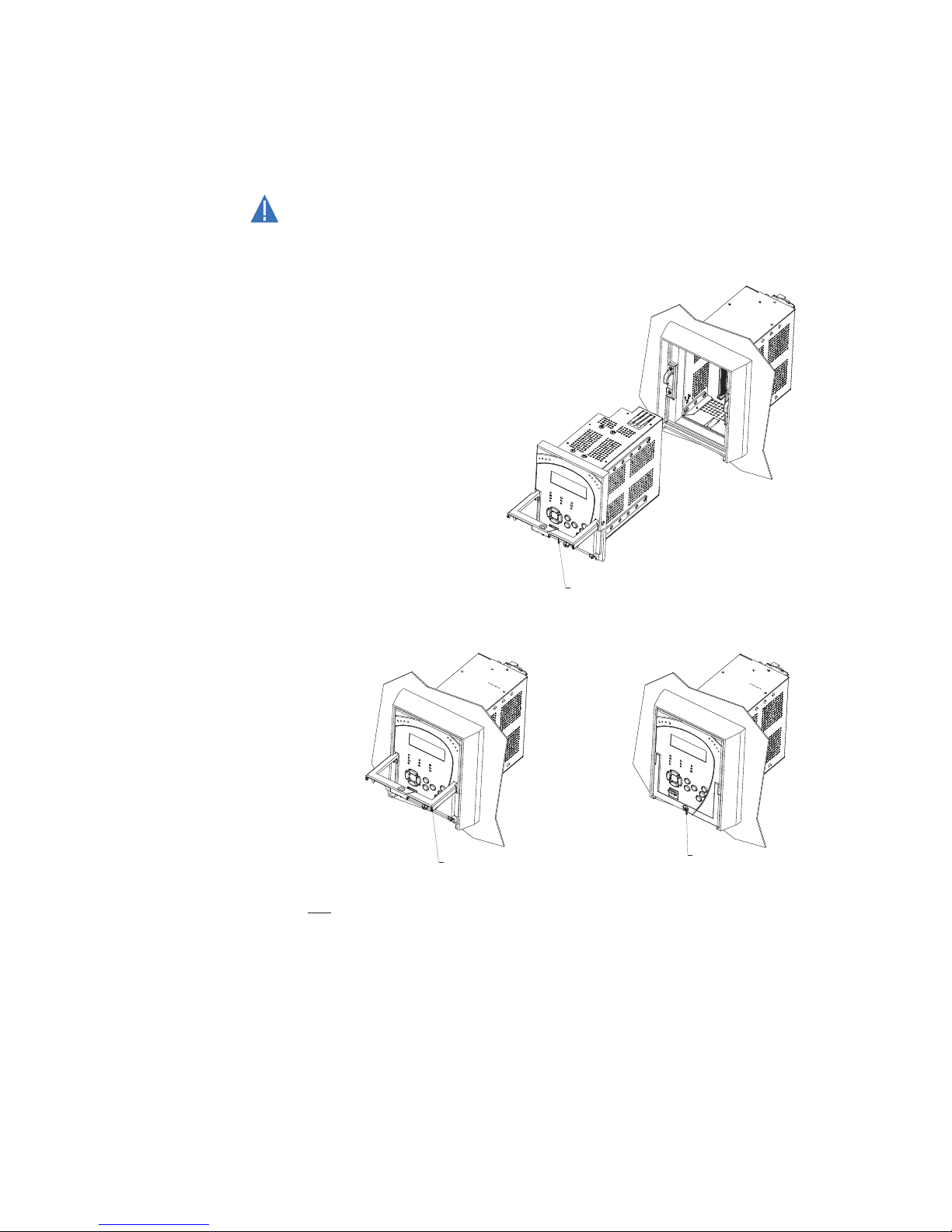
CAUTION
KEEP THE HANDLE IN ITS ROTATED
POSITION UNTIL THE DRAW-OUT UNIT
IS INSERTED COMPLETELY
PUSH THE HANDLE DOWN AND TIGHTEN
THE SCREW UNTIL THE HANDLE IS PARALLEL
WITH THE FRONT PANEL SURFACE
THE HANDLE MUST BE ROTATED 90
WHILE SLIDING THE 339 DRAW-OUT
UNIT INTO THE CAPTIVE UNIT
⁰
NOTE: IT IS THE RESPONSIBILITY OF THE USER TO ENSURE THAT THE EQUIPMENT IS INSTALLED, OPERATED, AND USED FOR ITS
INTENDED FUNCTION, IN THE MANNER SPECIFIED BY THE MANUFACTURER. IF THIS IS NOT THE CASE, THEN THE SAFETY PROTECTION
PROVIDED BY THE EQUIPMENT MAY BE IMPAIRED.
STEP 1
STEP 2
STEP 3
Mounting
STANDARD PANEL MOUNT
The standard panel mount and cutout dimensions are illustrated below.
CAUTION:
To avoid the potential for personal injury due to f ire hazards, ensure the unit is
mounted in a safe location and/or within an appropriate enclosure.
Figure 3: Panel mounting
339 MOTOR PROTECTION SYSTEM – INSTRUCTION MANUAL 2–3
Page 26
MECHANICAL INSTALLATION CHAPTER 2: INSTALLATION
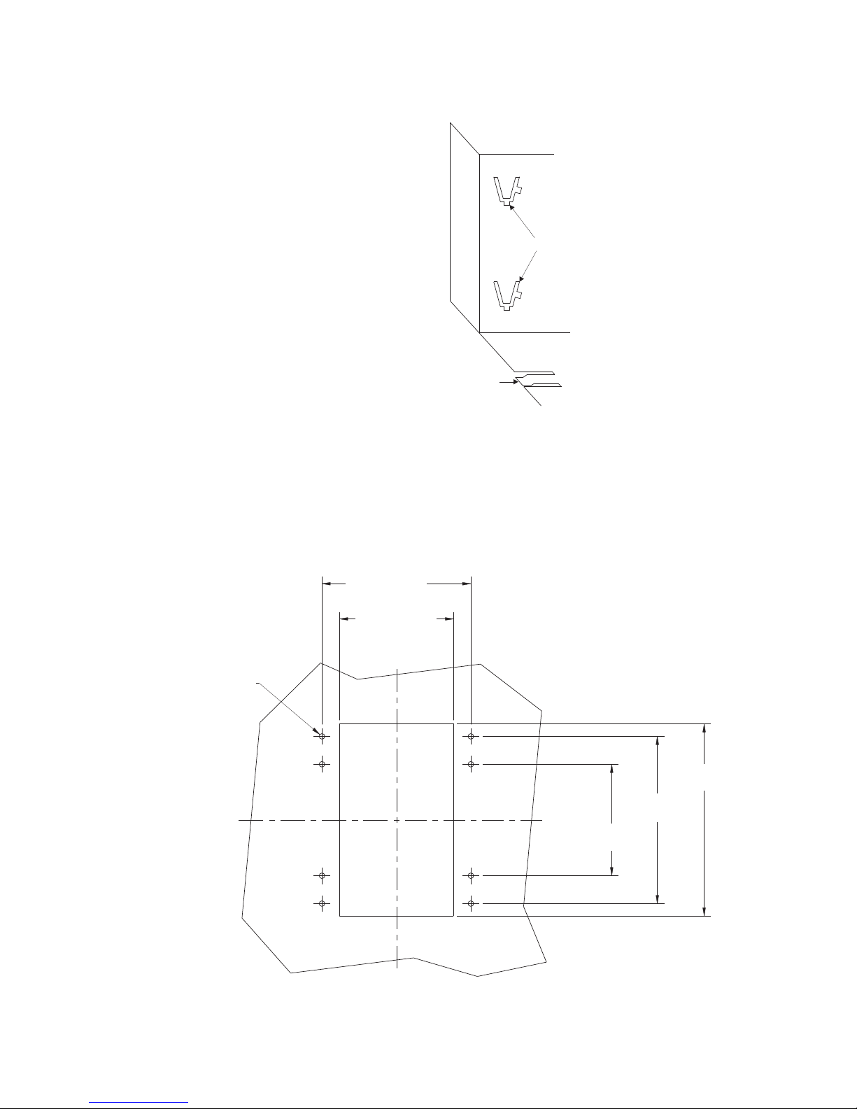
BOTTOM TAB
“V” TABS
5.350” 0.010”
(135.9 mm 0.25mm)
±
±
4.100” 0.010”
(104.1 mm 0.25 mm)
±
±
0.200”
(5.1 mm)
Φ
6.900” 0.010”
(175.3 mm 0.25 mm)
±
±
6.000” 0.010”
(152.4 mm 0.25 mm)
±
±
4.000” 0.010”
(101.6 mm 0.25 mm)
±
±
C
L
C
L
Figure 4: Mounting tabs (optional)
1. From the front of the panel, slide the empty case into the cutout until the bottom tab
clicks into place (see above).
2. From the rear of the panel screw the case into the panel at the 8 screw positions
shown above.
3. If added security is required, bend the retaining "V"tabs outward, to about 90°. These
tabs are located on the sides of the case and appear as shown above.
The relay can now be inserted and can be panel wired.
Figure 5: Panel cutout dimensions
2–4 339 MOTOR PROTECTION SYSTEM – INSTRUCTION MANUAL
Page 27

CHAPTER 2: INSTALLATION MECHANICAL INSTALLATION
SNAP-IN THE DIN CLIPS (QTY: 4)
FOR DIN RAIL MOUNTING
0.30”
(7,6 mm)
1.38”
(35,1 mm)
DIN 3 RAIL
853726A1.CDR
MEETS VIBRATION REQUIREMENT OF
IEC 60255 SEC 21.1, 21.2, & 21.3
2.250”
(57,15 mm)
#6 -32 THREADED HOLE
QTY: 2
4.100”
(104,14 mm)
853727A1.CDR
Figure 6: RMIO - DIN rail mounting - Base & Expansion units
Figure 7: RMIO - Base Unit screw mounting
339 MOTOR PROTECTION SYSTEM – INSTRUCTION MANUAL 2–5
Page 28
MECHANICAL INSTALLATION CHAPTER 2: INSTALLATION
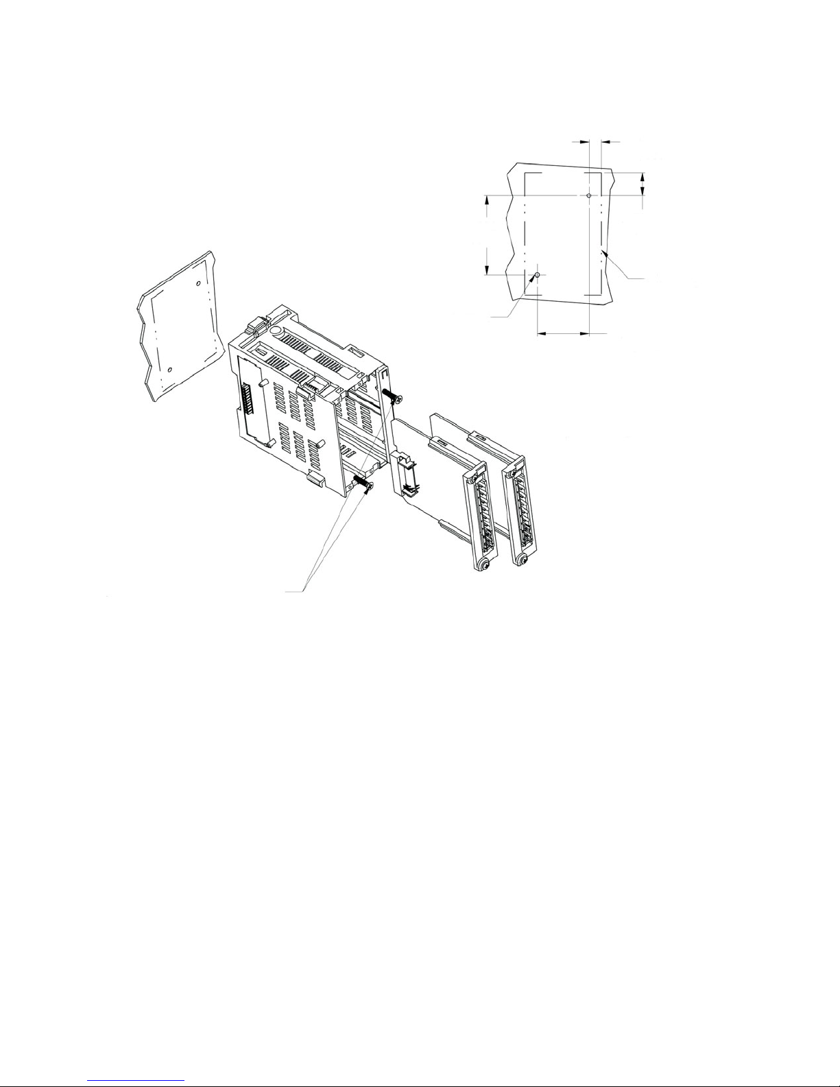
#6-32X1/2 FT FLAT HEAD PHIL ZINC
QTY: 2; (SUPPLIED); GE PART # 1406-0117
TIGHTENING TORQUE: 10 lb. in.
0.356”
[9.03 mm]
0.672”
[17.06 mm]
1.500”
[38.10 mm]
EXPANSION UNIT
OUTLINE
2.285”
[58.04 mm]
#6-32 THREADED HOLE
QTY: 2
853755A1.cdr
Figure 8: RMIO - Expansion Unit screw mounting
2–6 339 MOTOR PROTECTION SYSTEM – INSTRUCTION MANUAL
Page 29
CHAPTER 2: INSTALLATION MECHANICAL INSTALLATION
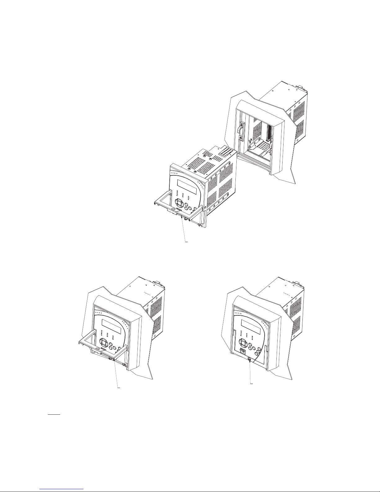
KEEP THE HANDLE IN ITS ROTATED
POSITION UNTIL THE DRAW-OUT UNIT
IS INSERTED COMPLETELY
PUSH THE HANDLE DOWN AND TIGHTEN
THE SCREW UNTIL THE HANDLE IS PARALLEL
WITH THE FRONT PANEL SURFACE
THE HANDLE MUST BE ROTATED 90
WHILE SLIDING THE 339 DRAW-OUT
UNIT INTO THE CAPTIVE UNIT
⁰
NOTE: IT IS THE RESPONSIBILITY OF THE USER TO ENSURE THAT THE EQUIPMENT IS INSTALLED, OPERATED, AND USED FOR ITS
INTENDED FUNCTION, IN THE MANNER SPECIFIED BY THE MANUFACTURER. IF THIS IS NOT THE CASE, THEN THE SAFETY PROTECTION
PROVIDED BY THE EQUIPMENT MAY BE IMPAIRED.
STEP 1
STEP 2
STEP 3
Unit withdrawal and insertion
Figure 9: Unit withdrawal and insertion diagram
339 MOTOR PROTECTION SYSTEM – INSTRUCTION MANUAL 2–7
Page 30
ELECTRICAL INSTALLATION CHAPTER 2: INSTALLATION
896729.CDR
POWER SUPPLY
B1
A1
B2
+
-
chassis
gnd
C1
C2
C3
C4
C5
C6
C7
C8
C9
C10
DIGITAL INPUTS
52a
52b
INPUT 3
INPUT 4
INPUT 5
INPUT 6
INPUT 7
INPUT 8
ETHERNET
RJ45
MTRJ
10/100BASE-T
100 BASE-FX
USB
TYPE B
A5
A6
A7
A2
A3
A4
A8
A9
A10
A11
A12
B3
B4
B5
B6
B7
B8
B9
B10
B11
B12
V
V
4 WIRE USB
4 WIRE ETHERNET
USB
+
F5 F4 F3
--
++
RS485
IRIG-B
F6F8
COMMUNICATIONS
CONTROL
POWER
A
B
C
E5
D5
E6
D6
E7
D7
E8
D8
1A/5A
VOLTAGE INPUTS
WYE VT
CONNECTION
E9
D9
E10
D10
E11
D11
V
AVA
V
B
V
B
V
C
V
C
7 CRITICAL
FAILURE
3START
INHIBIT
4 AUXILIARY
5 AUXILIARY
6 AUXILIARY
2 CLOSE
1 TRIP
OPTIONAL
Front Panel
Rear Panel
339
Motor Protection System
52a
Breaker Aux Contacts
E12
D12
CURRENTINPUTS
1A/5A
1A/5A
1A/5A
COM COM COM
COM
COM
50:0.025
PHASE A PHASE B
PHASE C
GROUND
SENS GROUND
MOTOR
DC
+
SELF TEST ANNUNCIATOR
TRIP
COIL
CLOSE
COIL
BREAKER CONTROL CIRCUIT
A5
A6
A7
A2
A3
A4
A8
A9
A10
A11
A12
B3
B4
B5
B6
B7
B8
B9
B10
B11
B12
V
V
+
7 CRITICAL
FAILURE
3START
INHIBIT
4 TRIP
5 AUXILIARY
6 AUXILIARY
2 NOT USED
1 NOT USED
SELF TEST ANNUNCIATOR
CONTACTO R
COIL
START
STOP
CC
STOP
START
52a
52b
CONTROL
POWER
H
L
A
B
C
C11
C12
COMMON
CHASSIS GND
INPUT 9
INPUT 10
CONTACTORCONTROL CIRCUIT
F2 F1
-
+
RMIO
F7
52b
OPEN DELTA VT CONNECTION
E9 D9 E10 D10E11 D11
GND STUD
Electrical installation
Figure 10: Typical Wiring Diagram
2–8 339 MOTOR PROTECTION SYSTEM – INSTRUCTION MANUAL
Page 31

CHAPTER 2: INSTALLATION ELECTRICAL INSTALLATION
INPUT 1
INPUT 2
INPUT 3
INPUT 4
INPUT 5
INPUT 6
INPUT 7
INPUT 8
INPUT 9
INPUT 10
INPUT COM
CHASSIS GND
PHASE A CT
PHASE B CT
PHASE C CT
GND CT
PHASE A VT
PHASE B VT
PHASE C VT
CBCT
PHASE A CT
PHASE B CT
PHASE C CT
GND CT
PHASE A VT
PHASE B VT
PHASE C VT
CBCT
■
■
■
■
■
■
■
■
IRIG-B +
IRIG-B RS485 +
RS485 RS485 COM
CHASSIS GND
RMIO+
RMIO-
POWER SUPPLY +
CHASSIS GND
TRIP COMM
CLOSE N/O
CLOSE OPTV
START INHIBIT COM
AUX 4 N/C
AUX 4 N/O
AUX 5 COM
AUX 6 N/C
AUX 6 N/O
CRIT FAIL COM
POWER SUPPLY -
TRIP N/O
TRIP OPTV
CLOSE COM
START INHIBIT N/C
START INHIBIT N/O
AUX 4 COM
AUX 5 N/C
AUX 5 N/O
AUX 6 COM
CRIT FAIL N/C
CRIT FAIL N/O
1
2
3
4
5
6
7
8
9
10
11
12
1
2
3
4
5
6
7
8
9
10
11
12
5
6
7
8
9
10
11
12
AB C DE
F
1
2
3
4
5
6
7
8
339 terminal identification
Figure 11: Terminal identification with switching device as BREAKER
339 MOTOR PROTECTION SYSTEM – INSTRUCTION MANUAL 2–9
Page 32

ELECTRICAL INSTALLATION CHAPTER 2: INSTALLATION
INPUT 1
INPUT 2
INPUT 3
INPUT 4
INPUT 5
INPUT 6
INPUT 7
INPUT 8
INPUT 9
INPUT 10
INPUT COM
CHASSIS GND
PHASE A CT
PHASE B CT
PHASE C CT
GND CT
PHASE A VT
PHASE B VT
PHASE C VT
CBCT
PHASE A CT
PHASE B CT
PHASE C CT
GND CT
PHASE A VT
PHASE B VT
PHASE C VT
CBCT
■
■
■
■
■
■
■
■
IRIG-B +
IRIG-B RS485 +
RS485 RS485 COM
CHASSIS GND
RMIO+
RMIO-
POWER SUPPLY +
CHASSIS GND
START INHIBIT COM
TRIP N/C
TRIP N/O
AUX 5 COM
AUX 6 N/C
AUX 6 N/O
CRIT FAIL COM
POWER SUPPLY -
START INHIBIT N/C
START INHIBIT N/O
TRIP COM
AUX 5 N/C
AUX 5 N/O
AUX 6 COM
CRIT FAIL N/C
CRIT FAIL N/O
1
2
3
4
5
6
7
8
9
10
11
12
1
2
3
4
5
6
7
8
9
10
11
12
5
6
7
8
9
10
11
12
AB C DE
F
1
2
3
4
5
6
7
8
Figure 12: Terminal identification with switching device as CONTACTOR
2–10 339 MOTOR PROTECTION SYSTEM – INSTRUCTION MANUAL
Page 33

CHAPTER 2: INSTALLATION ELECTRICAL INSTALLATION
Tx
Rx
IO_GIO_G
RCU
PSU
P
S
U
L
N
G
Com Port
+
-
Common
B1
B2
B3
14
13
12
11
10
9
8
7
6
5
4
3
2
1
14
13
12
11
10
9
8
7
6
5
4
3
2
1
896750.cdr
IO_GIO_G
14
13
12
11
10
9
8
7
6
5
4
3
2
1
14
13
12
11
10
9
8
7
6
5
4
3
2
1
RMIO module installation
The optional remote module (RMIO) is designed to be mounted near the motor. This
eliminates the need for multiple RTD cables to run back from the motor, which may be in a
remote location, to the switchgear. Although the RMIO is internally shielded to minimize
noise pickup and interference, it should be mounted away from high current conductors or
sources of strong magnetic fields.
Figure 13: RMIO unit showing 2 IO_G modules
Figure 14: RMIO terminal identification with 4 IO_G modules
339 MOTOR PROTECTION SYSTEM – INSTRUCTION MANUAL 2–11
Page 34

ELECTRICAL INSTALLATION CHAPTER 2: INSTALLATION
NOTE
SCADA, PLC, OR
PERSONAL COMPUTER
OPTOCOUPLER
DATA
RMIO
SHIELD
896740.CDR
(*) TERMINATING IMPEDANCE AT EACH END
(typically 120 ohms and 1 nF)
TWISTED PAIR
RMIO +
RMIO -
COMMON
GROUND THE SHIELD AT THE
SCADA/PLC/COMPUTER ONLY
OR THE MM300 ONLY
DATA
OPTOCOUPLER
B1
B2
B3
ZT(*)
339 IED
F7: RMIO+
F5: COM
F8: RMIO-
–
+
To switchgear
ground bus
Control power
LN
Motor
starter
Motor
Three-wire shielded cable
RTD
terminals in
motor starter
RTD terminals
at motor
Maximum total lead resistance:
25 ohms for Platinum RTDs
Route cable in separate conduit from
current carrying conductors
RTD in motor
stator or
bearing
896739.CDR
339 Motor Protection System
Surge ground
~13
~4
~3
~2
~1
Compensation
Return
Hot
Shield
RTD1
~8
~7
~6
~5
Compensation
Return
Hot
Shield
RTD2
~12
~11
~10
~9
Compensation
Return
Hot
Shield
RTD3
N/C
~14
Figure 15: RMIO wiring diagram
NOTE:
F5, F7, and F8 refer to terminals shown on the above 339 Terminal Identification diagrams.
Figure 16: RTD wiring
2–12 339 MOTOR PROTECTION SYSTEM – INSTRUCTION MANUAL
Page 35

CHAPTER 2: INSTALLATION ELECTRICAL INSTALLATION
CAUTION
CAUTION
Phase sequence and transformer polarity
For correct operation of the relay features, the user must follow the instrument
transformer polarities, shown in the Typical Wiring Diagram. Note the solid square
markings shown with all instrument transformer connections. When the connections
adhere to this drawing, the arrow shows the direction of power flow for positive watts and
the positive direction of lagging vars. The phase sequence is user programmable for either
ABC or ACB rotation.
Phase current inputs
The relay has three (3) channels for phase current inputs, each with an isolating
transformer. There are no internal ground connections on the current inputs. Current
transformers with 30 to 1500 A primaries may be used.
CAUTION:
Verify that the relay’s nominal input current of 1 A or 5 A matches the secondary rating
of the connected CTs. Unmatched CTs may result in equipment damage or inadequate
protection.
CAUTION:
Before working on CTs, they MUST be short circuited.
Ground and CBCT inputs
The 339 has two isolating transformers with separate terminals for the 1A/5A secondary
and the CBCT (50:0.025). Only one ground terminal type can be used at a time. There are no
internal ground connections on the ground current inputs.
The maximum ground CT primary for the 1 A and 5 A taps is 1500 A. Alternatively the
sensitive ground input, 50:0.025, can be used to detect ground current on high resistance
grounded systems.
The ground CT connection can either be a zero sequence (core balance) installation or a
residual connection. Note that only 1 A and 5 A secondary CTs may be used for the residual
connection. A typical residual connection is illustrated below. The zero-sequence
connection is shown in the typical wiring diagram. The zero-sequence connection is
recommended. Unequal saturation of CTs, CT mismatch, size and location of motor,
resistance of the power system, motor core saturation density, etc. may cause false
readings in the residually connected ground fault circuit.
339 MOTOR PROTECTION SYSTEM – INSTRUCTION MANUAL 2–13
Page 36

ELECTRICAL INSTALLATION CHAPTER 2: INSTALLATION
896827.cdr
CURRENT INPUTS
PHASE A PHASE B PHASE C GROUND
1A/5A COMCOM COM COM1A/5A 1A/5A 1A/5A
E5 D5 E6 E7 E8D6 D7 D8
PHASE A CT
PHASE B CT
PHASE C CT
A
B
C
Ground connection to neutral
must be on the source side
UNSHIELDED CABLE
LOAD
ABCN G
Ground
outside CT
Source
LOAD
SHIELDED CABLE
896791.CDR
ABC
Source
To ground;
must be on
load side
Stress cone
shields
SHIELDED TWISTED PAIR
SHIELDED TWISTED PAIR
Figure 17: Residual ground CT connection
Zero sequence CBCT installation
The exact placement of a zero sequence CT to properly detect ground fault current is
shown below. If the CT is placed over a shielded cable, capacitive coupling of phase current
into the cable shield during motor starts may be detected as ground current unless the
shield wire is also passed through the CT window. Twisted pair cabling on the zero
sequence CT is recommended
Figure 18: Zero sequence core balance (CT) installation
2–14 339 MOTOR PROTECTION SYSTEM – INSTRUCTION MANUAL
Page 37

CHAPTER 2: INSTALLATION ELECTRICAL INSTALLATION
NOTE
NOTE
CAUTION
CAUTION
CAUTION
NOTE
Voltage inputs
The relay has three channels for AC voltage inputs, each with an isolating transformer.
Voltage transformers up to a maximum 300:1 ratio may be used. The nominal secondary
voltage must be in the 50 to 240 V range. The three phase inputs are designated as the
“bus voltage”. The Bus VT connections most commonly used, wye and delta (or open delta),
are shown in the typical wiring diagram.
NOTE:
If Delta VTs are used, the zero sequence voltage (V0) will be zero. Also, with the Delta VT
connection, the phase-neutral voltage cannot be measured and will not be displayed.
NOTE:
CAUTION:
CAUTION:
CAUTION:
NOTE:
The relay can be applied to both metering and protection feeders with up to 20000 V
phase-to-phase voltage. Please ensure that the selected VT ratio and VT secondary do not
result in a primary voltage exceeding 20000 V.
Control power
Control power supplied to the relay must match the installed power supply range. If the
applied voltage does not match, damage to the unit may occur. All grounds MUST be
connected for safe, normal operation regardless of control power supply type.
The label found on the relay specifies its order code or model number. The installed power
supply’s operating range will be one of the following:
LO: 24 to 48 V DC (Nominal Range: 20 to 60 V DC)
HI: 125 to 250 V DC/120 to 240 V AC (Nominal Range: 84 to 250 V DC/60 to 300 V AC)
The relay chassis ground terminals should be connected directly to the ground bus,
using the shortest practical path. A tinned copper, braided, shielding and bonding
cable should be used. As a minimum, 96 strands of number 34 AWG should be used.
Belden catalog number 8660 is suitable.
Isolate power prior to servicing.
An external switch, circuit breaker, or other protective device must be connected close to
the equipment.
339 MOTOR PROTECTION SYSTEM – INSTRUCTION MANUAL 2–15
Page 38

ELECTRICAL INSTALLATION CHAPTER 2: INSTALLATION
CAUTION
PPOWER
OR BRAIDED WIRE
OR BRAIDED WIRE
HEAVY COPPER CONDUCTORHEAVY COPPER CONDUCTOR
GROUND BUSGROUND BUS
SWITCHGEAR
-
+
GROUND
B2
A1
B1
+-
CHASSIS
RELAY
CONTROL
898735.CDR898735.CDR
CONTROL
POWER
Wet Contact Connection
339 RELAY
C1Contact Input 1
Contact Input Common
C11
V DC Power
Supply
LOGICIN.CDR
Figure 19: Control power connection
Contact inputs
External contacts can be connected to the relay’s ten (10) digital inputs. These contacts are
wet only.
The inputs can be programmed to different thresholds depending on the DC voltage (17,
33, 84, 166).
CAUTION:
Ensure correct polarity on contact input connections and do not connect any contact
input circuits to ground or else relay hardware may be damaged.
A wet contact has one side connected to the positive terminal of an external DC power
supply. The other side of this contact is connected to the required contact input terminal. In
addition, the negative side of the external source must be connected to the relay’s DC
negative rail at Terminal C11. The maximum external source voltage for this arrangement
is 300 V DC.
Figure 20: Wet contact connections
Trip and Close output relays
The relay is equipped with seven electromechanical output relays: 2 Form A (Relay 1, Relay
2–16 339 MOTOR PROTECTION SYSTEM – INSTRUCTION MANUAL
2), and 5 Form C (Relays 3 to 7).
When SWITCHING DEVICE is selected as BREAKER:
Output Relays:
Page 39

CHAPTER 2: INSTALLATION ELECTRICAL INSTALLATION
• For special purpose:
– Output Relay 1 (non-failsafe, seal-in): Breaker Trip
– Output Relay 2 (non-failsafe, seal-in): Breaker Close
– Output Relay 3 (non-failsafe, self-reset): Start Inhibit
– Output Relay 7 (fail-safe, self-reset): Critical Failure
• For general purpose:
– Output Relays 4 to 6 - non-failsafe; can be programmed as self-reset or latched.
Operation of the Trip and Close output relays is designed to be controlled by the state of
the circuit breaker as monitored by a 52a or 52b contact.
• The Trip and Close relays reset after the breaker is detected in a state corresponding
to the command. When a relay feature sends a command to one of these special
relays, it will remain operational until the requested change of breaker state is
confirmed by a breaker auxiliary contact and the initiating condition has reset .
• If the initiating feature resets, but the breaker does not change state, the output relay
will be reset after a default interval of 2 seconds.
• If neither of the breaker auxiliary contacts, 52a nor 52b, is programmed to a contact
input, the Trip Relay is de-energized after either the delay programmed in the Breaker
Failure feature, or a default interval of 100 ms after the initiating input resets. The
Close Relay is de-energized after 200 ms.
• If a delay is programmed for the Trip or Close contact seal-in time, then this delay is
added to the reset time. Note that the default setting for the seal-in time is 40 ms.
52a Contact
Configured
Yes Yes Trip Relay remains operational until 52b indicates an
Yes No Trip Relay remains operational until 52a indicates an
No Yes Trip Relay remains operational until 52b indicates an
No No Trip Relay operates until either the Breaker Failure delay
52b Contact
Configured
Relay Operation
open breaker. Close Relay remains operational until 52a
indicates a closed breaker.
open breaker. Close Relay remains operational until 52a
indicates a closed breaker.
open breaker. Close Relay remains operational until 52b
indicates a closed breaker.
expires (if the Breaker Failure element is enabled), or 100
ms after the feature causing the trip resets. Close Relay
operates for 200 ms.
Breaker monitoring (Trip and Close coil monitoring) is performed by a built-in voltage
monitor on Form A output relays: #1 Trip, and #2 Close. The voltage monitor is connected
across each of the two Form A contacts, and the relay effectively detects healthy current
through the circuit. In order to do this, an external jumper must be connected between
terminals A2 and A3 for Trip coil monitoring, or/and B4, and B5 for Close coil monitoring.
As long as the current through the Voltage Monitor is above the threshold of the trickle
currents (see Technical Specification for Form A output relays), the circuit integrity for the
Trip (Close) coil is effectively normal. If the Trip (Close) coil circuit gets disconnected, or if in
general a high resistance is detected in the circuitry, a Trip (Close) alarm will be set and the
“ALARM” and “MAINTENANCE” LEDs will be on provided the corresponding Coil Monitor
feature is enabled.
Example: The figures below show the two different connections of the breaker trip (close)
coil to the relay’s trip output #1 terminals (close output #2 terminals) for both no voltage
monitoring and voltage monitoring of the trip (close) circuit integrity.
339 MOTOR PROTECTION SYSTEM – INSTRUCTION MANUAL 2–17
Page 40

ELECTRICAL INSTALLATION CHAPTER 2: INSTALLATION
V
A2
B3
A3
Trip
Coil
DC +
DC -
Output Relay 1 (TRIP)
52a
contact
V
B4
A4
B5
Close
Coil
DC +
DC -
Output Relay 2 (CLOSE)
52b
contact
896730.cdr
V
A2
B3
A3
Trip
Coil
DC +
DC -
Output Relay 1 (TRIP)
52a
contact
External
jumper
896731.cdr
V
B4
A4
B5
Close
Coil
DC +
DC -
Output Relay 2 (CLOSE)
52b
contact
External
jumper
NOTE:
To monitor the trip coil circuit integrity, use the relay terminals A2 and B3 to connect the
Trip coil, and provide a jumper between terminals A2 and A3 (optional voltage).
NOTE:
To monitor the close coil circuit integrity, use the relay terminals B4 and A4 to connect the
Close coil, and provide a jumper between terminals B4 and B5 (optional voltage).
Figure 21: Trip and Close Coil circuits with no voltage monitoring
NOTE:
All AUX contacts are shown when the breaker is open.
Figure 22: Trip and Close Coil circuits with voltage monitoring
When SWITCHING DEVICE is selected as CONTACTOR
Output Relays:
•Not Used:
–Output Relay 1
–Output Relay 2
• For special purpose:
– Output Relay 3 (self-reset): Start Inhibit
– Output Relay 4 (fail-safe, non-fail-safe): Trip
2–18 339 MOTOR PROTECTION SYSTEM – INSTRUCTION MANUAL
Page 41

CHAPTER 2: INSTALLATION ELECTRICAL INSTALLATION
CAUTION
SCADA, PLC, OR
PERSONAL COMPUTER
COM
OPTOCOUPLER
DATA
339C IED
SHIELD
896732.CDR
UP TO 32 339C
OR OTHER IEDs,
MAXIMUM CABLE
LENGTH OF
1200 m (4000 ft.)
LAST
DEVICE
(*) TERMINATING IMPEDANCE AT EACH END
(typically 120 ohms and 1 nF)
TWISTED PAIR
ZT(*)
RS485 +
RS485 -
COMMON
RS485 +
RS485 -
COMMON
IED
RS485 +
IED
RS485 -
COMMON
GROUND THE SHIELD AT THE
SCADA/PLC/COMPUTER ONLY
OR THE 339C ONLY
DATA
OPTOCOUPLER
F3
F4
F5
ZT(*)
– Output Relay 7 (fail-safe, self-reset): Critical Failure
• For general purpose:
– Output Relays 5 to 6: Can be programmed as fail-safe or non-failsafe, as well as
self-reset or latched.
Serial communications
Figure 23: RS485 wiring diagram
One two-wire RS485 port is provided. Up to 32 IEDs can be daisy-chained together on a
communication channel without exceeding the driver capability. For larger systems,
additional serial channels must be added. Commercially available repeaters can also be
used to add more than 32 relays on a single channel. Suitable cable should have a
should not exceed 1200 meters (4000 ft.). Commercially available repeaters will allow for
transmission distances greater than 1200 meters.
Voltage differences between remote ends of the communication link are not uncommon.
For this reason, surge protection devices are internally installed across all RS485 terminals.
characteristic impedance of 120 ohms (for example, Belden #9841) and total wire length
Internally, an isolated power supply with an optocoupled data interface is used to prevent
CAUTION:
noise coupling.
To ensure that all devices in a daisy-chain are at the same potential, it is imperative
that the common terminals of each RS485 port are tied together and grounded only
once, at the master or at the slave. Failure to do so may result in intermittent or failed
communications.
The source computer/PLC/SCADA system should have similar transient protection devices
installed, either internally or externally. Ground the shield at one point only, as shown in the
figure above, to avoid ground loops.
339 MOTOR PROTECTION SYSTEM – INSTRUCTION MANUAL 2–19
Page 42

ELECTRICAL INSTALLATION CHAPTER 2: INSTALLATION
GE MULTILIN
339 RELAY
IRIG-B(-)
RECEIVER
TO OTHER DEVICES
RG58/59 COAXIAL CABLE
GPS SATELLITE SYSTEM
GPS CONNECTION
OPTIONAL
IRIG-B(+)
F1
F2
+
–
896741.CDR
IRIG-B
TIME CODE
GENERATOR
(DC SHIFT OR
AMPLITUDE MODULATED
SIGNAL CAN BE USED)
Correct polarity is also essential. The IEDs must be wired with all the positive (+) terminals
connected together and all the negative (–) terminals connected together. Each relay must
be daisy-chained to the next one. Avoid star or stub connected configurations. The last
device at each end of the daisy-chain should be terminated with a 120 ohm ¼ watt
resistor in series with a 1 nF capacitor across the positive and negative terminals.
Observing these guidelines will ensure a reliable communication system immune to
system transients.
IRIG-B
IRIG-B is a standard time code format that allows time stamping of events to be
synchronized among connected devices within 1 millisecond. The IRIG time code formats
are serial, width-modulated codes which can be either DC level shift or amplitude
modulated (AM) form. The type of form is auto-detected by the relay. Third party
equipment is available for generating the IRIG-B signal; this equipment may use a GPS
satellite system to obtain the time reference so that devices at different geographic
locations can also be synchronized.
Figure 24: IRIG-B connection
2–20 339 MOTOR PROTECTION SYSTEM – INSTRUCTION MANUAL
Page 43

Digital Energy
Multilin
339 Motor Protection System
Chapter 3: Interfaces
Interfaces
There are two methods of interfacing with the 339 Motor Protection System.
• Interfacing via the relay keypad and display.
• Interfacing via the software.
This section provides an overview of the interfacing methods available with the 339 using
the relay control panel and software. For additional details on interface parameters (for
example, settings, actual values, etc.), refer to the individual chapters.
339 MOTOR PROTECTION SYSTEM – INSTRUCTION MANUAL 3–1
Page 44

FRONT CONTROL PANEL INTERFACE CHAPTER 3: INTERFACES
▽
△
◁▷
▲
▼
ENTER
MENU
ESCAPE
RESET
896351A1.cdr
USB
GE Multilin
339 Motor
Protection System
IN SERVICE
TROUBLE
LOCKOUT
START
INHIBIT
TRIP
ALARM
PICKUP
MAINTENANCE
STOPPED
STARTING
RUNNING
HOT RTD
Front control panel interface
Figure 1: 339 Motor Protection System front panel
Description
The relay front panel provides an interface with a liquid crystal display, LED status
indicators, control keys, and a USB program port. The display and status indicators show
the relay information automatically. The control keys are used to select the appropriate
message for entering setpoints or displaying measured values. The USB program port is
also provided for connection with a computer running the EnerVista SR3 Setup software.
3–2 339 MOTOR PROTECTION SYSTEM – INSTRUCTION MANUAL
Page 45

CHAPTER 3: INTERFACES FRONT CONTROL PANEL INTERFACE
█
ACTUAL VALUES
QUICK SETUP
SETPOINTS
MAINTENANCE
█
MOTOR STATUS
A1 STATUS
CLOCK
CONTACT INPUTS
█
ACTUAL VALUES
A1 STATUS
A2 METERING
A3 RECORDS
█
CLOCK
A1 STATUS
CONTACT INPUTS
MOTOR STATUS
█
A1 STATUS
RTD TEMP SUMMARY
.
.
.
2 clicks
▽
△
▶
▶
▼
◁▷
▼
▼
◁▷
Click to end
▼
Back
Back
Back
1 click
Display
The 80-character liquid crystal display (LCD) allows visibility under varied lighting
conditions. When the keypad and display are not being used, system information is
displayed after a user-defined period of inactivity. Pressing the Menu key during the
display of the default message returns the display to the last message shown before the
default message appeared. Any trip, alarm, or pickup is displayed immediately,
automatically overriding the default message.
Working with the
Keypad
The display messages are organized into a Main Menu, pages, and sub-pages. There are
four main menus labeled Actual Values, Quick Setup, Setpoints, and Maintenance. Pressing
the MENU key followed by the MESSAGE key scrolls through the four Main Menu headers,
which appear in sequence as follows:
Figure 2: The four Main Menu headers
Pressing the MESSAGE ► key or the ENTER key from these Main Menu pages will display
the corresponding menu Page. Use the MESSAGE ▲ and MESSAGE ▼ keys to scroll through
the Page headers.
Figure 3: Typical paging operation from Main Menu selection
339 MOTOR PROTECTION SYSTEM – INSTRUCTION MANUAL 3–3
Page 46

FRONT CONTROL PANEL INTERFACE CHAPTER 3: INTERFACES
When the display shows SETPOINTS, pressing the MESSAGE ► key or the ENTER key will
display the page headers of programmable parameters (referred to as setpoints in the
manual). When the display shows ACTUAL VALUES, pressing the MESSAGE ► key or the
ENTER key displays the page headers of measured parameters (referred to as actual
values in the manual).
Each page is broken down further into logical sub-pages of messages. The MESSAGE ▲
and MESSAGE ▼ keys are used to navigate through the sub-pages. A summary of the
setpoints and actual values pages can be found in the Chapters : Setpoints and Actual
Values, respectively.
The ENTER key is dual purpose. It is used to enter the sub-pages and to store altered
setpoint values into memory to complete the change. The MESSAGE ► key can also be
used to enter sub-pages but not to store altered setpoints.
The ESCAPE key or the MESSAGE key can be used to exit the sub-pages.
The VALUE keys are used to scroll through the possible choices of an enumerated setpoint.
They also decrement and increment numerical setpoints.
The RESET key resets any latched conditions that are not currently active. This includes
resetting latched output relays, latched Trip LEDs, breaker operation failure, and trip / close
coil failures.
The MESSAGE ▲ and MESSAGE ▼ keys scroll through any active conditions in the relay.
Diagnostic messages are displayed indicating the state of protection and monitoring
elements that are picked up, operating, or latched.
LED status indicators
• IN SERVICE: Green
– Turns "ON" when the relay does not have any major self-test error.
– Minor self-test targets will not de-activate the LED.
• TROUBLE: Amber
– Turns "ON" when either a major or minor self-test error has occurred.
– Will be latched "ON" for major self-test errors, except for "RELAY NOT READY".
– Will be self-resetting for minor self-test errors.
• TRIP: Red
– Turns "ON" when a protection element has been assigned to trip and the element
has been activated.
– Will be latched "ON" until a reset command occurs.
– Turns "OFF" when a reset has been initiated through the front panel,
communications, or digital inputs, and the fault has been cleared.
• ALARM: Amber
– Flashes "ON" and "OFF" when a protection, control, or maintenance element has
been assigned to alarm and the element has been activated.
– Will be latched "ON" if "Latched Alarm" is set and the fault has been cleared.
– Will be self-resetting if "Alarm" is set and the fault has been cleared.
– Turns "OFF" when a reset has been initiated through the front panel or
communications, and the fault has been cleared, if "Latched Alarm" is set.
• PICKUP: Amber
– Turns "ON" when a protection element setting threshold has been exceeded. LED
will turn "OFF" when the values go below the threshold.
• MAINTENANCE: Amber
– Turns "ON" when either the Trip or the Close Coil Monitor element is activated, or
the Trip Counter has exceeded the programmed value.
3–4 339 MOTOR PROTECTION SYSTEM – INSTRUCTION MANUAL
Page 47

CHAPTER 3: INTERFACES FRONT CONTROL PANEL INTERFACE
• LOCKOUT: Red
– Turns "ON" when the following elements are activated:
Thermal Overload
Short Circuit
Mechanical Jam
Ground Fault.
– Can be reset only by emergency restart or lockout reset, if they are enabled.
– If the above are not enabled, a normal reset will turn the LED "OFF".
• START INHIBIT: Red
– Turns "ON" when the Start Inhibit element is activated.
– Self-resetting when the inhibit is no longer present.
• STOPPED: Default to Red
– LED color is programmable. Turns "ON" when the motor status is "Stopped".
• STARTING: Default to Amber
– LED color is programmable. Turns "ON" when the motor status is "Starting".
• RUNNING: Default to Green
– LED color is programmable. Turns "ON" when the motor status is "Running".
• HOT RTD: Amber
– Turns "ON" when either a RTD Alarm or Trip has been activated.
– Self-resetting when the fault is no longer present.
339 MOTOR PROTECTION SYSTEM – INSTRUCTION MANUAL 3–5
Page 48

FRONT CONTROL PANEL INTERFACE CHAPTER 3: INTERFACES
A4 TARGET MESSAGES
Cause <function>
State: Operate
Phase:
Relay messages
Default message Figure 4: Relay default messages
Target messages Target messages are automatically displayed for any active condition on the relay such as
pickups, trips, or alarms.
The relay displays and rolls up target messages until the conditions clear and/or the RESET
command is initiated. The Target Messages can be reviewed by pressing either the
MESSAGE UP or MESSAGE DOWN key. If a RESET command is not performed but any of the
other faceplate pushbuttons is pressed, the display will not show the target messages
unless the user navigates to
reviewed. If the target messages have not been cleared before the user presses a
pushbutton different from “RESET”, they will reappear on the screen after the time specified
under the
that will start timing out from the last pressed pushbutton. The following shows the format
of a typical Target Message:
Figure 5: Typical target message
3–6 339 MOTOR PROTECTION SYSTEM – INSTRUCTION MANUAL
ACTUAL VALUES > A4 TARGET MESSAGES, where they can be
SETPOINTS > S1 RELAY SETUP > S1 FRONT PANEL > MESSAGE TIMEOUT setting,
Page 49

CHAPTER 3: INTERFACES FRONT CONTROL PANEL INTERFACE
CAUTION
A4 TARGET MESSAGES
Ph IOC1 Trip
State: Operate
Phase:A
▼
A4 TARGET MESSAGES
UNIT FAILURE:
Contact Factory:
Error code:1
Figure 6: Example of Trip on Phase A
Cause <Function>
This line contains information of the cause of operation (the name of the operated
element), and the element function.
State: Operate
This line from the display shows the state of the element: Pickup, Operate, Alarm.
Phase: A
The last line from the display shows the phase that picked up or operated.
Self-test errors The relay performs self diagnostics at initialization (after power up), and continuously as a
background task to ensure that the hardware and software are functioning correctly.
There are two types of self-test warnings indicating either a minor or major problem. Minor
problems indicate a problem with the relay that does not compromise protection of the
power system. Major errors indicate a problem with the relay which takes it out of service.
CAUTION:
Self-Test Warnings may indicate a serious problem with the relay hardware!
Upon detection of a minor problem, the relay will:
• Turn on the "TROUBLE" LED at the same time as the "IN SERVICE" LED is on.
• Display the error on the relay display.
• Record the minor self-test error in the Event Recorder.
Upon detection of a major problem, the relay will:
• De-energize critical failure relay (Output Relay 7).
• Inhibit operation of all other output relays (1 to 6).
• Turn off the "IN SERVICE" LED.
• Turn on the "TROUBLE" LED.
•Flash the "ALARM" LED.
• Display the cause of major self-test failure.
• Record the major self-test failure in the Event Recorder.
Figure 7: Typical Self-test warning
339 MOTOR PROTECTION SYSTEM – INSTRUCTION MANUAL 3–7
Page 50

FRONT CONTROL PANEL INTERFACE CHAPTER 3: INTERFACES
Table 1: Minor Self-test Errors
Self-test Error
Message
MAINTENANCE
ALERT: IRIG-B
Failure
MAINTENANCE
ALERT: Clock
Not Set
MAINTENANCE
ALERT: Comm
Alert 1, 2, or 3
MAINTENANCE
ALERT :
Ethernet Link
Fail
MAINTENANCE
ALERT: High
Ethernet
Traffic
MAINTENANCE
ALERT: High
Ambient
Temperature
MAINTENANCE
ALERT : RMIO
Mismatch
Latched
Target
Description of
Problem
How Often the Test
is Performed
Message?
No A bad IRIG-B input
Every 5 seconds* Ensure IRIG-B cable is
signal has been
detected.
No Clock time is the
Every 5 seconds* Set the date and time in
same as the default
time.
No Communication
Every 5 seconds* If alert doesn’t self-reset,
error between CPU
and Comms board.
No Communication
error between 339
Detected
Instantaneously
and Network.
No Every 5 seconds*
No The ambient
temperature is
above 80
o
C.
No RMIO Module is not
Every 1 hour Increase ventillation to the
Every 5 seconds* Validate the RMIO Module;
validated;
communications
with the RMIO
module are lost or
interrupted.
What to do
connected, check cable
functionality (i.e. physical
damage or perform
continuity test), ensure
IRIG-B receiver is
functioning, and check
input signal level (it may
be less than specification).
If none of these apply,
contact the factory.
S1 RELAY SETUP.
then contact factory.
Otherwise monitor
recurrences as errors are
detected and self-reset.
Check Ethernet cable and
Ethernet connection.
Check health of the
network. Check status of
external routers and
switches.
surroundings.
check CANBUS
communication.
Table 2: Major Self-test Errors
Self-test Error
Message
UNIT FAILURE:
Contact
Factory
(XXXX)
RELAY NOT
READY: Check
Settings
1.Failure is logged after the detection of 5 consecutive failures - that is, after 25 seconds.
3–8 339 MOTOR PROTECTION SYSTEM – INSTRUCTION MANUAL
Latched
Target
Description of
Problem
Message?
Yes This warning is
caused by a unit
hardware failure.
Failure code (XXXX) is
shown.
No S1 RELAY SETUP >
INSTALLATION >
RELAY STATUS is set
to "Not Ready".
How Often the Test
is Performed
Every 5 seconds
1
On power up and
whenever the RELAY
STATUS setting is
altered.
What to do
Contact the factory and
provide the failure code.
Program all required
settings then set the S1
RELAY SETUP >
INSTALLATION > RELAY
STATUS setting to "Ready".
Page 51

CHAPTER 3: INTERFACES FRONT CONTROL PANEL INTERFACE
BLOCK 1
Logic Element 8
S3 SHORT CIRCUIT
<SETPOINT STORED>
Flash messages Flash messages are warning, error, or general information messages displayed in response
to pressing certain keys.
Figure 8: Typical Flash message
SETPOINT STORED
This flash message is displayed in response to the ENTER key while on any setpoint
message (see example above). The edited value was stored as entered.
COMMAND EXECUTED
This flash message is displayed in response to executing a command: ON, OFF, YES, NO,
etc.
INVALID PASSWORD
This flash message appears upon an attempt to enter an incorrect password, as part of
password security.
339 MOTOR PROTECTION SYSTEM – INSTRUCTION MANUAL 3–9
Page 52

SOFTWARE SETUP CHAPTER 3: INTERFACES
Software setup
Quick setup - Software interface
• The Quick Setup window allows you to configure important settings from different
screens in the relay by adding them to a common window.
• The Quick Setup window options are available for online devices or setpoint files.
• The Quick Setup Window option is accessed from the "Tree" which launches on
clicking.
EnerVista SR3 Setup Software
Although settings can be entered manually using the control panel keys, a PC can be used
to download setpoints through the communications port. The software is available from
GE Multilin to make this as convenient as possible. With the 339 relay running, it is possible
to:
• Program and modify settings
• Load and save setting files to and from a disk
• Read actual values
• Monitor status
• Read pre-trip data and event records
• Get help on any topic
• Upgrade the firmware
3–10 339 MOTOR PROTECTION SYSTEM – INSTRUCTION MANUAL
Page 53

CHAPTER 3: INTERFACES SOFTWARE SETUP
The software allows immediate access to all features with easy to use pull down menus in
the familiar Windows environment. This section provides the necessary information to
install the 339, upgrade the relay firmware, and write and edit setting files.
The software can run without a 339 connected to the computer. In this case, settings may
be saved to a file for future use. If a 339 is connected to a PC and communications are
enabled, the 339 can be programmed from the setting screens. In addition, measured
values, status and trip messages can be displayed with the actual value screens.
Hardware and
software
requirements
Installing the
EnerVista SR3 Setup
software
The following requirements must be met for the software.
• Microsoft Windows™ 2000 / XP / Vista is installed and running properly.
• At least 100 MB of hard disk space is available.
• At least 256 MB of RAM is installed.
The software can be installed from either the GE EnerVista CD or the GE Multilin website at
http://www.GEmultilin.com.
After ensuring the minimum requirements indicated earlier, use the following procedure to
install the EnerVista SR3 Setup software from the enclosed GE EnerVista CD.
1. Insert the GE EnerVista CD into your CD-ROM drive.
2. Follow the installation instructions to install the no-charge EnerVista software on the
local PC.
3. When installation is complete, start the EnerVista Launchpad application.
4. Click the IED Setup section of the LaunchPad toolbar.
5. In the EnerVista Launchpad window, click the Add Product button and select the
Feeder Protection System as shown below. Select the Web option to ensure the most
recent software release, or select CD if you do not have a web connection, then click
the Add Now button to list software items for the .
339 MOTOR PROTECTION SYSTEM – INSTRUCTION MANUAL 3–11
Page 54

SOFTWARE SETUP CHAPTER 3: INTERFACES
6. EnerVista Launchpad will obtain the latest installation software from the Web or CD
and automatically start the installation process. A status window with a progress bar
will be shown during the downloading process.
7. Select the complete path, including the new directory name, where the software will
be installed.
8. Click on Next to begin the installation. The files will be installed in the directory
indicated, the USB driver will be loaded into the computer, and the installation
program will automatically create icons and add software to the Windows start
menu.
9. The device will be added to the list of installed IEDs in the EnerVista Launchpad
window, as shown below.
3–12 339 MOTOR PROTECTION SYSTEM – INSTRUCTION MANUAL
Page 55

CHAPTER 3: INTERFACES SOFTWARE SETUP
If you are going to communicate from your computer to the Relay using the USB port:
10. Plug the USB cable into the USB port on the Relay then into the USB port on your
computer.
11. Launch EnerVista SR3 Setup from LaunchPad.
12. In EnerVista > Device Setup:
339 MOTOR PROTECTION SYSTEM – INSTRUCTION MANUAL 3–13
Page 56

SOFTWARE SETUP CHAPTER 3: INTERFACES
Connecting EnerVista SR3 Setup to the relay
Configuring serial
communications
13. Select USB as the Interface type.
14. Select Relay as the USB device.
Before starting, verify that the cable is properly connected to either the USB port on the
front panel of the device (for USB communications) or to the RS485 terminals on the back
of the device (for RS485 communications). This example demonstrates an USB connection.
For RS485 communications, the GE Multilin F485 converter will be required. Refer to the
F485 manual for additional details. To configure the relay for Ethernet communications,
see Configuring Ethernet Communications below.
1. Install and start the latest version of the software (available from the GE Multilin web
site). See the previous section for the installation procedure.
2. Click on the Device Setup button to open the Device Setup window and click the Add
Site button to define a new site.
3. Enter the desired site name in the "Site Name" field. If desired, a short description of
the site can also be entered. In this example, we will use “Substation 1” as the site
name.
4. The new site will appear in the upper-left list in the window.
5. Click the Add Device button to define the new device.
6. Enter the desired name in the "Device Name" field and a description (optional) of the
device.
7. Select “Serial” from the Interface drop-down list.
3–14 339 MOTOR PROTECTION SYSTEM – INSTRUCTION MANUAL
Page 57

CHAPTER 3: INTERFACES SOFTWARE SETUP
Using the Quick
Connect feature
8. Click the Read Order Code button to connect to the device and upload the order
code.
9. Click OK when the relay order code has been received. The new device will be added
to the Site List window (or Online window) located in the top left corner of the main
window.
The Site Device has now been configured for USB communications. Proceed to Connecting
to the Relay below, to begin communications.
The Quick Connect button can be used to establish a fast connection through the front
panel USB port of a relay, or through the Ethernet port. The following window will appear
when the QuickConnect button is pressed:
339 MOTOR PROTECTION SYSTEM – INSTRUCTION MANUAL 3–15
Page 58

SOFTWARE SETUP CHAPTER 3: INTERFACES
NOTE
As indicated by the window, the "Quick Connect" feature can quickly connect the software
to a front port if the USB is selected in the interface drop-down list . Select " Relay" and
press the Connect button. Ethernet can also be used as the interface for Quick Connect as
shown above.
When connected, a new Site called “Quick Connect” will appear in the Site List window.
The Site Device has now been configured via the Quick Connect feature for either USB or
Ethernet communications. Proceed to Connecting to the Relay below, to begin
communications.
Configuring Ethernet
communications
NOTE:
3–16 339 MOTOR PROTECTION SYSTEM – INSTRUCTION MANUAL
Before starting, verify that the Ethernet cable is properly connected to the RJ-45 Ethernet
port.
The 339 relay supports a maximum of 3 TCP/IP sessions.
Page 59

CHAPTER 3: INTERFACES SOFTWARE SETUP
1. Install and start the latest version of the Setup software (available from the GE
EnerVista CD). See the previous section for the installation procedure.
2. Click on the Device Setup button to open the Device Setup window and click the Add
Site button to define a new site.
3. Enter the desired site name in the "Site Name" field. If desired, a short description of
the site can also be entered. In this example, we will use “Substation 1” as the site
name.
4. The new site will appear in the upper-left list.
5. Click the Add Device button to define the new device.
6. Enter the desired name in the "Device Name" field, and a description (optional).
7. Select “Ethernet” from the Interface drop-down list. This will display a number of
interface parameters that must be entered for proper Ethernet functionality.
8. Enter the IP address, slave address, and Modbus port values assigned to the relay
9. Click the Read Order Code button to connect to the and upload the order code. If a
10. Click OK when the relay order code has been received. The new device will be added
The Site Device has now been configured for Ethernet communications. Proceed to the
following section to begin communications.
Connecting to the
relay
Now that the communications parameters have been properly configured, the user can
easily communicate with the relay.
1. Expand the Site list by double clicking on the site name or clicking on the «+» box to
339 MOTOR PROTECTION SYSTEM – INSTRUCTION MANUAL 3–17
(from the S1 RELAY SETUP > COMMUNICATIONS > ETHERNET menu).
communications error occurs, ensure that the Ethernet communication values
correspond to the relay setting values.
to the Site List window (or Online window) located in the top left corner of the main
window.
list the available devices for the given site.
Page 60

SOFTWARE SETUP CHAPTER 3: INTERFACES
2. Desired device trees can be expanded by clicking the «+» box. The following list of
headers is shown for each device:
Device Definition
Actual Values
Quick Setup
Setpoints
Maintenance.
3. Expand the SETTINGS > RELAY SETUP list item and double click on Front Panel to open
the "Front Panel" settings window as shown below:
4. The "Front Panel" settings window will open with a corresponding status indicator on
the lower left of the EnerVista SR3 Setup window.
5. If the status indicator is red, verify that the serial, USB, or Ethernet cable is properly
connected to the relay, and that the relay has been properly configured for
communications (steps described earlier).
The "Front Panel" settings can now be edited, printed, or changed. Other setpoint and
command windows can be displayed and edited in a similar manner. "Actual Values"
windows are also available for display. These windows can be arranged, and resized at will.
Working with setpoints and setpoint files
Engaging a device The software may be used in on-line mode (relay connected) to directly communicate with
a relay. Communicating relays are organized and grouped by communication interfaces
and into sites. Sites may contain any number of relays selected from the product series.
Entering setpoints The System Setup page will be used as an example to illustrate the entering of setpoints. In
this example, we will be changing the voltage sensing setpoints.
3–18 339 MOTOR PROTECTION SYSTEM – INSTRUCTION MANUAL
Page 61

CHAPTER 3: INTERFACES SOFTWARE SETUP
1. Establish communications with the relay.
2. Select the Setpoint > System Setup > Voltage Sensing menu item.
3. Select the Bus VT Secondary setpoint by clicking anywhere in the parameter box. This
will display three arrows: two to increment/decrement the value and another to
launch the numerical keypad.
4. Clicking the arrow at the end of the box displays a numerical keypad interface that
allows the user to enter a value within the setpoint range displayed near the top of the
keypad: Click = to exit from the keypad and keep the new value. Click on X to exit from
the keypad and retain the old value.
5. For setpoints requiring non-numerical pre-set values (e.g. 3-Phase voltage
6. For setpoints requiring an alphanumeric text string (e.g. "relay name"), the value may
7. In the Setpoint > System Setup > Voltage Sensing dialog box, click on Save to save
339 MOTOR PROTECTION SYSTEM – INSTRUCTION MANUAL 3–19
connection below), clicking anywhere within the setpoint value box displays a dropdown selection menu arrow. Select the desired value from this list.
be entered directly within the setpoint value box.
the values into the . Click YES to accept any changes and exit the window. Click
Restore to retain previous values. Click Default to restore Default values.
Page 62

SOFTWARE SETUP CHAPTER 3: INTERFACES
File support Opening any file will automatically launch the application or provide focus to the already
opened application. If the file is a settings file (has a ‘SR3’ extension) which had been
removed from the Settings List tree menu, it will be added back to the Settings List tree.
New files will be automatically added to the tree.
Using setpoints files The software interface supports three ways of handling changes to relay settings:
• In off-line mode (relay disconnected) to create or edit relay settings files for later
download to communicating relays.
• Directly modifying relay settings while connected to a communicating relay, then
saving the settings when complete.
• Creating/editing settings files while connected to a communicating relay, then saving
them to the relay when complete.
Settings files are organized on the basis of file names assigned by the user. A settings file
contains data pertaining to the following types of relay settings:
• Device Definition
•Relay Setup
•System Setup
•Protection
• Control
• Inputs/Outputs
Factory default values are supplied and can be restored after any changes.
The displays relay setpoints with the same hierarchy as the front panel display.
Downloading and
saving setpoints files
Adding setpoints files
to the environment
Setpoints must be saved to a file on the local PC before performing any firmware
upgrades. Saving setpoints is also highly recommended before making any setpoint
changes or creating new setpoint files.
The setpoint files in the window are accessed in the Files Window. Use the following
procedure to download and save setpoint files to a local PC.
1. Ensure that the site and corresponding device(s) have been properly defined and
configured as shown in Connecting to the Relay, above.
2. Select the desired device from the site list.
3. Select the Online > Read Device Settings from Device menu item, or right-click on the
device and select Read Device Settings to obtain settings information from the
device.
4. After a few seconds of data retrieval, the software will request the name and
destination path of the setpoint file. The corresponding f ile extension will be
automatically assigned. Press Receive to complete the process. A new entry will be
added to the tree, in the File pane, showing path and file name for the setpoint file.
The software provides the capability to review and manage a large group of setpoint files.
Use the following procedure to add an existing file to the list.
3–20 339 MOTOR PROTECTION SYSTEM – INSTRUCTION MANUAL
Page 63

CHAPTER 3: INTERFACES SOFTWARE SETUP
1. In the files pane, right-click on Files and select the Add Existing Setting File item as
shown:
Creating a new
setpoint file
2. The Open dialog box will appear, prompting the user to select a previously saved
setpoint file. As for any other MS Windows® application, browse for the file to be
added then click Open. The new file and complete path will be added to the file list.
The software allows the user to create new setpoint files independent of a connected
device. These can be uploaded to a relay at a later date. The following procedure illustrates
how to create new setpoint files.
1. In the File pane, right click on File and select the New Settings File item. The following
box will appear, allowing for the configuration of the setpoint file for the correct
firmware version. It is important to define the correct firmware version to ensure that
setpoints not available in a particular version are not downloaded into the relay.
339 MOTOR PROTECTION SYSTEM – INSTRUCTION MANUAL 3–21
Page 64

SOFTWARE SETUP CHAPTER 3: INTERFACES
2. Select the Firmware Version, and Order Code options for the new setpoint file.
3. For future reference, enter some useful information in the Description box to facilitate
the identification of the device and the purpose of the file.
4. To select a file name and path for the new file, click the button beside the File Name
box.
5. Select the file name and path to store the file, or select any displayed file name to
replace an existing file. All setpoint files should have the extension ‘SR3’ (for example,
‘feeder1.SR3’).
6. Click OK to complete the process. Once this step is completed, the new file, with a
complete path, will be added to the software environment.
Upgrading setpoint
files to a new revision
It is often necessary to upgrade the revision for a previously saved setpoint file after the
firmware has been upgraded. This is illustrated in the following procedure:
1. Establish communications with the relay.
2. Select the Maintenance > M1 Relay Info menu item and record the Firmware
Revision.
3. Load the setpoint file to be upgraded into the EnerVista SR3 Setup environment as
described in the section, Adding Setpoints Files to the Environment.
4. In the File pane, select the saved setpoint file.
5. From the main window menu bar, select the Offline > Edit Settings File Properties
menu item and note the File Version of the setpoint file. If this version is different from
the Firmware Revision noted in step 2, select a New File Version that matches the
Firmware Revision from the pull-down menu.
3–22 339 MOTOR PROTECTION SYSTEM – INSTRUCTION MANUAL
Page 65

CHAPTER 3: INTERFACES SOFTWARE SETUP
6. For example, if the firmware revision is L2L01MA120.000 (Firmware Revision 1.20) and
the current setpoint file revision is 1.10, change the setpoint file revision to “1.2x”.
Printing setpoints and
actual values
7. Enter any special comments about the setpoint file in the "Description" field.
8. Select the desired firmware version from the "New File Version" field.
9. When complete, click OK to convert the setpoint file to the desired revision. See
Loading Setpoints from a File below, for instructions on loading this setpoint file into
the 339.
The software allows the user to print partial or complete lists of setpoints and actual
values. Use the following procedure to print a list of setpoints:
1. Select a previously saved setpoints file in the File pane or establish communications
with a device.
2. From the main window, select the Offline > Export Settings File menu item.
3. The Print/Export Options dialog box will appear. Select Settings in the upper section
and select either Include All Features (for a complete list) or Include Only Enabled
Features (for a list of only those features which are currently used) in the filtering
section and click OK.
339 MOTOR PROTECTION SYSTEM – INSTRUCTION MANUAL 3–23
Page 66

SOFTWARE SETUP CHAPTER 3: INTERFACES
Printing actual values
from a connected
device
4. The process for Offline > Print Preview Settings File is identical to the steps above.
5. Setpoint lists can be printed in the same manner by right clicking on the desired file (in
the file list) or device (in the device list) and selecting the Print Device Information or
Print Settings File options.
A complete list of actual values can also be printed from a connected device with the
following procedure:
1. Establish communications with the desired device.
2. From the main window, select the Online > Print Device Information menu item
3. The Print/Export Options dialog box will appear. Select Actual Values in the upper
section and select either Include All Features (for a complete list) or Include Only
Enabled Features (for a list of only those features which are currently used) in the
filtering section and click OK.
Actual values lists can be printed in the same manner by right clicking on the desired
device (in the device list) and selecting the Print Device Information option
3–24 339 MOTOR PROTECTION SYSTEM – INSTRUCTION MANUAL
Page 67

CHAPTER 3: INTERFACES SOFTWARE SETUP
CAUTION
L2 L01 M A 100 . 000
Modification Number (000 = none)
Board Assembly Rev #
Code Type in Memory Device
PCB Code Number
Product Reference Code (L2 = 339)
Firmware Rev #
Loading setpoints
from a file
CAUTION:
An error message will occur when attempting to download a setpoint file with a
revision number that does not match the relay firmware. If the firmware has been
upgraded since saving the setpoint file, see Upgrading Setpoint Files to a New Revision,
above, for instructions on changing the revision number of a setpoint file.
The following procedure illustrates how to load setpoints from a file. Before loading a
setpoints file, it must first be added to the environment as described in the section, Adding
Setpoints Files to the Environment.
1. Select the previously saved setpoints file from the File pane of the EnerVista SR3 Setup
software main window.
2. Select the Offline > Edit Settings File Properties menu item and verify that the
corresponding file is fully compatible with the hardware and firmware version of the
target relay. If the versions are not identical, see Upgrading Setpoint Files to a New
Revision, above, for details on changing the setpoints file version.
3. Right-click on the selected file and select the Write Settings File to Device item.
4. Select the target relay from the list of devices shown and click Send. If there is an
incompatibility, an "Incompatible Device" error message will occur:
If there are no incompatibilities between the target device and the settings file, the data
will be transferred to the relay. An indication of the percentage completed will be shown in
the bottom of the main window.
NOTE:
NOTE:
Loading new relay
Upgrading relay firmware
To upgrade the firmware, follow the procedures listed in this section. Upon successful
completion of this procedure, the will have new firmware installed with the factory default
setpoints.The latest firmware files are available from the GE Multilin website at http://
www.GEmultilin.com.
EnerVista SR3 Setup software prevents incompatible firmware from being loaded into a
relay.
Before upgrading firmware, it is very important to save the current 339 settings to a file on
your PC. After the firmware has been upgraded, it will be necessary to load this file back
into the . Refer to Downloading and Saving Setpoints Files for details on saving relay
setpoints to a file.
Loading new firmware into the flash memory is accomplished as follows:
firmware
1. Connect the relay to the local PC and save the setpoints to a file as shown in
Downloading and Saving Setpoints Files.
2. Select the Maintenance > Update Firmware menu item.
3. The software will request the new firmware file. Locate the folder that contains the
firmware files to load into the . The firmware filename has the following format:
339 MOTOR PROTECTION SYSTEM – INSTRUCTION MANUAL 3–25
Page 68

SOFTWARE SETUP CHAPTER 3: INTERFACES
4. EnerVista SR3 Setup software now prepares the to receive the new firmware file. The
front panel will momentarily display "SR BOOT PROGRAM Waiting for Message,”
indicating that it is in upload mode.
5. While the file is being loaded into the , a status box appears showing how much of the
new firmware file has been transferred and the upgrade status. The entire transfer
process takes approximately 10 minutes.
6. The software will notify the user when the has finished loading the file. Carefully read
any displayed messages and click OK to return the main screen. Cycling power to the
relay is recommended after a firmware upgrade.
After successfully updating the firmware, the relay will not be operational and will require
setpoint programming. To communicate with the relay, the communication settings may
have to be manually reprogrammed.
When communications are established, the saved setpoints must be reloaded back into
the relay. See Loading Setpoints from a File for details.
Modbus addresses assigned to firmware modules, features, settings, and corresponding
data items (i.e. default values, min/max values, data type, and item size) may change
slightly from version to version of the firmware. Addresses are rearranged when new
features are added or existing features are enhanced or modified.
3–26 339 MOTOR PROTECTION SYSTEM – INSTRUCTION MANUAL
Page 69

CHAPTER 3: INTERFACES SOFTWARE SETUP
Advanced EnerVista SR3 Setup features
Data logger The data logger feature is used to sample and record up to ten actual values at a
selectable interval. The datalogger can be run with Continuous mode Enabled, which will
continuously record samples until stopped by the user; or with Continuous mode Disabled,
which will trigger the datalog once without overwriting previous data.
Select the Setpoints > S1RelaySetup > Datalogger menu item to open the Datalogger
Setup window.
Viewing and saving of the Datalogger is performed as follows:
1. With EnerVista SR3 Setup running and communications established, select the A3
Records > Datalogger menu item to open the Datalogger Actual Values window:
2. If Continuous mode is enabled, click on Stop to stop the datalog
3. Click on the Save to File button to save the datalog to the local PC. A new window will
appear requesting for file name and path.
4. One file is saved as a COMTRADE file, with the extension ‘CFG’. The other file is a DAT
file, required by the COMTRADE file for proper display of data.
5. To view a previously saved COMTRADE file, click the Open button and select the
corresponding COMTRADE file.
6. To view the datalog, click the Launch Viewer button. A detailed Datalog window will
appear as shown below.
339 MOTOR PROTECTION SYSTEM – INSTRUCTION MANUAL 3–27
Page 70

SOFTWARE SETUP CHAPTER 3: INTERFACES
Display graph values
at the corresponding
cursor line. Cursor
lines are identified by
their colors.
CURSOR
LINES
To move lines locate the mouse pointer
over the cursor line then click and drag
the cursor to the new location.
DELTA
Indicates time difference
between the two cursor lines
TRIGGER LINE
Indicates the
point in time for
the trigger
FILE NAME
Indicates the
file name and
complete path
(if saved)
TRIGGER TIME & DATE
Display the time & date of the
Trigger
CURSOR LINE POSITION
Indicate the cursor line position
in time with respect to the
trigger time
7. The method of customizing the datalog view is the same as the Waveform Capture
described below.
8. The datalog can be set to capture another buffer by clicking on Run (when Continuous
mode is enabled), or by clicking on Release (when Continuous mode is disabled).
Motor start data
logger
When a motor start status is detected by the 339 relay, a start data logger is triggered and
begins to sample and record the following parameters at a rate of 1 sample every 200ms:
• True RMS values of the Phase A, B and C Currents (Ia, Ib, and Ic).
3–28 339 MOTOR PROTECTION SYSTEM – INSTRUCTION MANUAL
• True RMS value of the Ground current (Ig).
• Current Unbalance (%).
Page 71

CHAPTER 3: INTERFACES SOFTWARE SETUP
• True RMS values of the Phase A-N, B-N, and C-N voltages (Van, Vbn, and Vcn) if VT
CONNECTION TYPE is set to Wye.
• True RMS values of the Phase A-B, B-C and C-A voltages (Vab, Vbc, and Vca) if VT
CONNECTION TYPE is set to Delta.
• Thermal Capacity Used (%).
•Frequency.
• Breaker/Contactor Contact Input Status.
1-second pre-trigger data and 29-second post-trigger data are recorded. The data logger
ignores all subsequent triggers and continues to record data until the active record is
finished.
A total of 6 logs are stored in the relay. Log # 1 is the baseline log; it is written to only by the
first start that occurs after the user clears the motor start data logger. Logs #2 to 6 are a
rolling buffer of the last 5 motor starts. A new log automatically shifts the rolling buffer and
overwrites the oldest log, #2.
The log files are formatted using CSV (comma delimited values) and the COMTRADE file
format per IEEE PC37.111 Draft 7C (02 September 1997). [Please see the details in the user
interfaces section.] The files can be downloaded and displayed via EnerVista SR3 Setup
software. All the files are stored in non-volatile memory, so that information is retained
when power to the relay is lost.
Viewing and saving of the Motor Start Datalogger is performed as follows:
1. With EnerVista SR3 Setup running and communications established, select the A3
Records > Motor Start Data Logger menu item to open the Motor Start datalog setup
window:
2. Click on the Save to File button to save the datalog to the local PC. A new window will
appear requesting for file name and path.
3. One file is saved as a COMTRADE file, with the extension ‘CFG’. The other file is a DAT
file, required by the COMTRADE file for proper display of data.
4. To view a previously saved COMTRADE file, click the Open button and select the
corresponding COMTRADE file.
5. To view the datalog, click the Launch Viewer button. A detailed Datalog window will
appear as shown below. For an explanation of the components of this screen, please
refer to the Data Logger section above.
339 MOTOR PROTECTION SYSTEM – INSTRUCTION MANUAL 3–29
Page 72

SOFTWARE SETUP CHAPTER 3: INTERFACES
Transient recorder
(Waveform capture)
6. The method of customizing the datalog view is the same as the Waveform Capture
described below.
The EnerVista SR3 Setup software can be used to capture waveforms (or view trace
memory) from the relay at the instance of a pickup, trip, alarm, or other condition.
• With software running and communications established, select the Actual Values >
A3 Records > Transient Records menu item to open the Transient Recorder Viewer
window.
•Click on Trigger Waveform to trigger a waveform capture. Waveform file numbering
starts with the number zero in the , so that the maximum trigger number will always
be one less than the total number of triggers available.
3–30 339 MOTOR PROTECTION SYSTEM – INSTRUCTION MANUAL
Page 73

CHAPTER 3: INTERFACES SOFTWARE SETUP
Display graph values
at the corresponding
cursor line. Cursor
lines are identified
b
y their colors.
FILE NAME
Indicates the
file name and
complete path
(if saved).
CURSOR LINES
To move lines, locate the mouse
pointer over the cursor line, then
click and drag the cursor to the
new position.
TRIGGER LINE
Indicates the point
in time for the
trigger.
TRIGGER TIME & DATE
Displays the time and date
of the Trigger.
VECTOR DISPLAY SELECT
Click here to open a new graph
to display vectors.
CURSOR LINE POSITION
Indicates the cursor line position
in time with respect to the
beginning of the buffer.
DELTA
Indicates time difference
between the two cursor
lines.
•Click on the Save to File button to save the selected waveform to the local PC. A new
window will appear, requesting the file name and path. One file is saved as a
COMTRADE file, with the extension "CFG." The other file is a "DAT" file, required by the
COMTRADE file for proper display of waveforms.
• To view a previously saved COMTRADE file, click the Open button and select the
corresponding COMTRADE file.
• To view the captured waveforms, click on the Launch Viewer button. A detailed
Waveform Capture window will appear as shown below.
• The red vertical line indicates the trigger point.
• The date and time of the trigger are displayed at the top left corner of the window. To
339 MOTOR PROTECTION SYSTEM – INSTRUCTION MANUAL 3–31
match the captured waveform with the event that triggered it, make note of the time
and date shown in the graph, then find the event that matches the same time in the
Page 74

SOFTWARE SETUP CHAPTER 3: INTERFACES
Preference Button
event recorder. The event record will provide additional information on the cause and
system conditions at the time of the event .
• From the window main menu bar, press the Preference button to open the COMTRADE
Setup page, in order to change the graph attributes.
The following window will appear:
Change the color of each graph as desired, and select other options as required, by
checking the appropriate boxes. Click OK to store these graph attributes, and to close the
window. The Waveform Capture window will reappear based on the selected graph
attributes.
To view a vector graph of the quantities contained in the waveform capture, press the
Vector Display button to display the following window:
3–32 339 MOTOR PROTECTION SYSTEM – INSTRUCTION MANUAL
Page 75

CHAPTER 3: INTERFACES SOFTWARE SETUP
Protection summary Protection Summary is a single screen which holds the summarized information of
different settings from Grouped Elements, Control Elements and Maintenance screens.
Protection Summary Screen allows the User to:
• view the output relay assignments for the elements
• modify the output relay assignments for the elements
• view the enable/disable status of Control Elements
• navigate to the respected Protection Element screen on a button click.
The Protection Summary screen is as follows:
339 MOTOR PROTECTION SYSTEM – INSTRUCTION MANUAL 3–33
Page 76

SOFTWARE SETUP CHAPTER 3: INTERFACES
Password security Password security is an optional feature of the which can be setup using the SR3 EnerVista
Setup software. The password system has been designed to facilitate a hierarchy for
centralized management. This is accomplished through a Master level access password
which can be used for resetting lower level access passwords and higher level privileged
operations. In cases where operational security is required as well as a central
administrative authority then the use of the password system is highly encouraged. The
feature robustness of this system requires it to be managed exclusively through the
EnerVista setup software. This section describes how to perform the initial setup. For more
details on the password security feature, refer to Chapter 6 - Password Security.
3–34 339 MOTOR PROTECTION SYSTEM – INSTRUCTION MANUAL
Page 77

CHAPTER 3: INTERFACES SOFTWARE SETUP
1. 339 devices shipped from the factory are initially set with security disabled. If the
password security feature is to be used, the user must first change the Master Reset
Password from the initial Null setting, this can only be done over communications, not
from the front panel keypad. The new Master Reset Password must be 8 to 10
characters in length, and must have minimum 2 letters and 2 numbers. The letters
are case sensitive. After entering a valid Master Reset Password, enter the new
Master Reset Password again to confirm, then select Change Password.
2. Now that the Master Reset Password has been programmed, enter it again to log in to
the Master Access level. The Master Level permits setup of the Remote and Local
Passwords. If the Master Reset Password has been lost, record the Encrypted Key and
contact the factory to have it decrypted.
3. With Master Level access, the user may disable password security altogether, or
change the Master Reset Password.
4. The Master Access level allows programming of the Remote Setpoint and Remote
Control passwords. These passwords are initially set to a Null value, and can only be
set or changed from a remote user over RS485 or Ethernet communications. Remote
Passwords must be 3 to 10 characters in length.
5. Initial setup of the Local Setpoint and Local Control passwords requires the Master
Access level. If Overwrite Local Passwords is set to YES, Local passwords can be
changed remotely only (over RS485 or Ethernet). If Overwrite Local Passwords is set to
339 MOTOR PROTECTION SYSTEM – INSTRUCTION MANUAL 3–35
Page 78

SOFTWARE SETUP CHAPTER 3: INTERFACES
NO, Local passwords can be changed locally only (over USB or keypad). If changing
Local Passwords is permitted locally, the keypad user can only change the Local
Passwords if they have been changed from the initial NULL value to a valid one. Local
Passwords must be 3 to 10 characters in length.
6. If any Remote password has never been set, that level will not be attainable except
when logged in as the Master Level. The same logic applies to the Local passwords.
7. When passwords have been set, the user will be prompted to enter the appropriate
password depending on the interface being used (remote or local), and the nature of
the change being made (setpoint or control). If the correct password is entered, the
user is now logged into that access level over that interface only. The access level
turns off after a period of 5 minutes of inactivity, if control power is cycled, or if the
user enters an incorrect password.
3–36 339 MOTOR PROTECTION SYSTEM – INSTRUCTION MANUAL
Page 79

Digital Energy
Multilin
339 Motor Protection System
Chapter 4: Actual values
Actual values
Actual values overview
All measured values, the status of digital inputs and outputs, and fault analysis information
are accessed in Actual Values mode. Actual value messages are organized into logical
groups for easy reference as shown below.
339 MOTOR PROTECTION SYSTEM – INSTRUCTION MANUAL 4–1
Page 80

ACTUAL VALUES OVERVIEW CHAPTER 4: ACTUAL VALUES
A2 METERING
CURRENT
VOLTAGE
POWER
ENERGY
RTD TEMP
CLEAR ENERGY
▼
A1 STATUS
MOTOR STATUS
CLOCK
CONTACT INPUTS
OUTPUT RELAYS
LOGIC ELEMENTS
VIRTUAL INPUTS
REMOTE INPUTS
REMOTE OUTPUTS
C. INPUTS SUMMARY
OUT RELAYS SUMMARY
LOGIC ELEM SUMMARY
GOOSE STATUS
GOOSE HDR STATUS
RTD TEMP SUMMARY
▼
ACTUAL VALUES
A1 STATUS
A2 METERING
A3 RECORDS
A4 TARGET MESSAGES
▼
896760A1.cdr
A3 RECORDS
LEARNED DATA
LEARNED DATA REC
CLEAR LEARNED DATA
EVENT RECORDS
TRANSIENT RECORDS
CLEAR EVENT REC
CLEAR TRANST REC
▼
A4 TARGET MESSAGES
A2 VOLTAGE
AN VOLTAGE
▼
BN VOLTAGE
CN VOLTAGE
AVG PHASE VOLTAGE
AB VOLTAGE
BC VOLTAGE
CA VOLTAGE
AVG LINE VOLTAGE
NEG SEQ VOLTAGE
FREQUENCY
A2 POWER
3PH REAL POWER
▼
3PH REACTIVE POWER
3PH APPARENT PWR
POWER FACTOR
A2 ENERGY
POSITIVE WATTHOUR
▼
NEGATIVE WATTHOUR
POSITIVE VARHOUR
NEGATIVE VARHOUR
A2 RTD TEMPERATURE
RTD1 TEMPERATURE
RTD2 TEMPERATURE
...
RTD12 TEMPERATURE
▼
A3 TRANSIENT RECORDS
AVAILABLE RECORDS
FORCE TRIGGER?
TOTAL RECORDS
LAST CLEARED
▼
A2 CURRENT
PH A CURRENT
▼
PH B CURRENT
PH C CURRENT
AVG PHASE CURRENT
GND / SENS GND CURRENT
NTRL CURRENT
A3 LEARNED DATA
LEARNED START TCU
LEARNED ACCEL TIME
LEARNED START CURR
LAST ACCEL TIME
LAST START CURR
LAST START TCU
LEARNED AVG LOAD
AVG RUN TIME
RTD #1 MAX TEMP
RTD #2 MAX TEMP
...
RTD #12 MAX TEMP
▼
Figure 1: Main Actual Values menu
4–2 339 MOTOR PROTECTION SYSTEM – INSTRUCTION MANUAL
Page 81

A1 CONTACT INPUTS
CONTACT INPUT 1
CONTACT INPUT 2
...
CONTACT INPUT 10
▼
A1 CLOCK
CURRENT DATE
CURRENT TIME
▼
A1 STATUS
MOTOR STATUS
CLOCK
CONTACT INPUTS
LOGIC ELEMENTS
VIRTUAL INPUTS
REMOTE INPUTS
REMOTE OUTPUTS
C. INPUTS SUMMARY
OUT RELAYS SUMMARY
LOGIC ELEM SUMMARY
GOOSE STATUS
GOOSE HDR STATUS
RTD TEMP SUMMARY
OUTPUT RELAYS
▼
896748A1.cdr
A1 OUTPUT RELAYS
OUTPUT RELAY 1
OUTPUT RELAY 2
...
OUTPUT RELAY 6
OUTPUT RELAY 7
▼
A1 LOGIC ELEMENTS
LOGIC ELEMENT 1
2
...
16
LOGIC ELEMENT
LOGIC ELEMENT
▼
A1 VIRTUAL INPUTS
1
2
...
32
VIRTUAL INPUT
VIRTUAL INPUT
VIRTUAL INPUT
▼
A1 REMOTE INPUTS
1
2
...
32
REMOTE INPUT
REMOTE INPUT
REMOTE INPUT
▼
A1 OUTPUTS
1
2
...
32
REMOTE
REMOTE OUTPUTS
REMOTE OUTPUTS
REMOTE OUTPUTS
▼
A1 MOTOR STATUS
MOTOR STATUS
MOTOR LOAD
BIASED MOTOR LOAD
MOTOR TCU
MOTOR SPEED
O/L TIME TO TRIP
MOTOR LOCKOUT TIME
THERMAL O/L LKT
THERMAL INHIBIT
STARTS/HR INHIBIT
TIME-BTWN-STARTS
RESTART INHIBIT
CURRENT UNBALANCE
HOTTEST STATOR RTD
HOTTEST RTD NO
MOTOR RUNNING HOUR
MOTOR STARTS NUM
EMERG RESTARTS NUM
▼
CHAPTER 4: ACTUAL VALUES A1 STATUS
A1 Status
Figure 2: Status menu
339 MOTOR PROTECTION SYSTEM – INSTRUCTION MANUAL 4–3
Page 82

A1 STATUS CHAPTER 4: ACTUAL VALUES
Motor status
MOTOR STATUS
Range: Tripped, Stopped, Starting, Running, Overload
The motor status is tripped following any protection trip operation or lockout. After all
protection trips and lockout have cleared, the tripped motor status can be reset from the
front panel reset key, by closure of the reset or lockout reset contact input, or via
communications. The emergency restart function also resets tripped status.
When the motor status is stopped, detection of phase current above the FLA changes
the status to starting. Running status follows starting when the current then drops
below FLA. Running status continues as long as phase current greater than 5% of CT is
detected. To accommodate applications where current does not rise above the thermal
overload pickup setting on start, running status is also declared when the contact inputs
indicate the motor is online. When phase current falls below 5% of CT the status
changes to stopped. To accommodate applications where motor idle current is less
than 5% CT, a further requirement to change status to stopped is that the contact inputs
do not indicate the motor is online.
For single speed applications, an enabled 52a contact input closed or an enabled 52b
contact input open is taken as indication of motor online. If both are enabled, the relay
assumes the motor is online if the 52a contact is closed and the 52b contact is open.
For two speed applications, closure either of the High Speed Switch contact input or of
the Low Speed Switch contact input is indication of motor online. If either 52a or 52b
contact input is enabled, a further requirement is that these indicate the breaker is
closed.
Use of these contact inputs (52a Contact, 52b Contact, High Speed Switch, Low Speed
Switch) for motor online detection is optional, but is recommended to ensure proper
detection of motor running, especially in cases where the starting current is less than the
thermal overload pickup setting or motor idle current is less than 5% of CT.
MOTOR LOAD
Displays the average 3-phase motor current (I
BIASED MOTOR LOAD
Displays the equivalent motor heating current (I
Thermal Protection section.
MOTOR TCU
Displays the Thermal Capacity Used.
MOTOR SPEED
Indicates the motor running speed per the speed switch input. This value is seen only
when the setting "Enable 2-SPD Motor" is enabled.
O/L TIME TO TRIP
Displays the remainder of the thermal overload trip time when the current is above the
thermal overload pick-up setting.
THERMAL INHIBIT
Time in seconds left until the Thermal Start Inhibit expires. Has a value of zero if this
feature is set to OFF, or if the time has expired.
STARTS/HR INHIBIT
Time in seconds left until the Starts per Hour feature’s inhibit expires. Has a value of zero
if this feature is set to OFF, or if the time has expired.
) per-unit on an FLA base.
avg
) per-unit on an FLA base. Refer to
eq
4–4 339 MOTOR PROTECTION SYSTEM – INSTRUCTION MANUAL
Page 83

CHAPTER 4: ACTUAL VALUES A1 STATUS
CONTACT INPUT
52a Contact Input
SETTINGS
52b Contact Input
SETTING
= Enabled
Enable Two Speed
OPERAND
Motor Online
AND
AND OR
AND
CONTACT INPUT
High Speed Switch
Low Speed Switch
OR
AND
OR
AND
AND
OR
= Enabled
52a Contact
= Enabled
52 b Contact
AND
896839.cdr
TIME-BTWN-START
Time in seconds left until the Time Between Starts feature’s inhibit expires. Has a value
of zero if this feature is set to OFF, or if the time has expired.
RESTART INHIBIT
Time in seconds left until the Restart Timer feature’s inhibit expires. Has a value of zero if
this feature is set to OFF, or if the time has expired.
MOTOR LOCKOUT TIME
Displays the longest lockout time among the following 5 timers: THERMAL INHIBIT,
STARTS/HOUR INHIBIT, TIME-BETWEEN-STARTS INHIBIT, RESTART INHIBIT and THREMAL
O/L LOCKOUT.
THERMAL O/L LKT
A thermal overload lockout will occur after a thermal overload trip so that the user
cannot start the motor until the TCU drops to 15%. Following a thermal overload trip, this
value indicates how long it will take for the 339 relay TCU to decrease from the current
value to 15%.
CURRENT UNBALANCE
Displays the current unbalance level as a percentage. Refer to the Current Unbalance
section.
HOTTEST STATOR RTD
Displays the temperature of the hottest Stator RTD.
HOTTEST RTD NO.
Indicates the hottest Stator RTD.
MOTOR RUNNING HOUR
Displays the actual motor running time in hours.
MOTOR STARTS NUM
Displays the actual number of motor starts.
EMERG RESTARTS NUM
Displays the actual number of motor Emergency Restarts.
Figure 3: Motor Status logic diagram
339 MOTOR PROTECTION SYSTEM – INSTRUCTION MANUAL 4–5
Page 84

A1 STATUS CHAPTER 4: ACTUAL VALUES
Clock
PATH: ACTUAL VALUES > A1 STATUS > CLOCK
CURRENT DATE
Feb 12 2009
Range: Date in format shown
Indicates today’s date.
CURRENT TIME
09:17:12
Range: Time in format shown
Indicates the current time of day.
Contact inputs
PATH: ACTUAL VALUES > A1 STATUS > CONTACT INPUTS
52a (CI #1)
OFF
Range: Off, On
Shows the input status when connected to a 52a breaker auxiliary contact.
52b (CI #2)
OFF
Range: Off, On
Shows the breaker status when connected to a 52b breaker auxiliary contact.
CONTACT INPUT 3 to 10
OFF
Range: Off, On
Message displays the state of the contact input. The message “ON” indicates that the
contact input is energized, and message “OFF” indicates a de-energized contact.
Output relays
Output relays -
Breaker
PATH: ACTUAL VALUES > A1 STATUS > OUTPUT RELAYS
Output Relay #1 (TRIP)
OFF
Range: Off, On
The “ON” state of Output Relay #1 (Breaker TRIP) shows that a TRIP command has been
sent to the breaker.
Output Relay #2 (CLOSE)
OFF
Range: Off, On
The “ON” state of Output Relay #2 (Breaker CLOSE) shows that a CLOSE command has
been sent to the breaker.
Output Relay #3 (START INHIBIT)
OFF
Range: Off, On
4–6 339 MOTOR PROTECTION SYSTEM – INSTRUCTION MANUAL
Page 85

CHAPTER 4: ACTUAL VALUES A1 STATUS
Output Relay #4 to #6 (AUXILIARY OUTPUT RELAYS)
OFF
Range: Off, On
Output Relay #7 (CRITICAL FAILURE)
Range: Off, On
The "ON" state indicates that the relay is in-service.
Output relays -
Contactor
Logic elements
Output Relay #1 (Not Used)
Output Relay #2 (Not Used)
Output Relay #3 (START INHIBIT)
OFF
Range: Off, On
The "ON" state of Output Relay #3 (Start Inhibit) shows that a "block motor start"
command has been sent to the contactor.
Output Relay #4 (Contactor TRIP)
Range: Off, On
The "OFF" state of Output Relay #4 (Contactor TRIP) shows that a "TRIP" command has
been sent to the contactor.
Output Relay #5 to #6 (AUXILIARY OUTPUT RELAYS)
Range: Off, On
Output Relay #7 (CRITICAL FAILURE RELAY)
Range: Off, On
The "ON" state indicates that the relay is in service.
PATH: ACTUAL VALUES > A1 STATUS > LOGIC ELEMENTS
LOGIC ELEMENT 1 to 16
OFF
Range: Off, On
The state “ON” or “OFF” for each logic element depends on its programmed logic:
triggering inputs, blocking inputs, plus any pickup, and/or reset time delay.
Virtual inputs
The state of all virtual inputs is displayed here.
PATH:
VIRTUAL INPUTS 1 to 32
OFF
Remote inputs
The state of all remote inputs is displayed here.
PATH:
REMOTE INPUTS 1 to 32
OFF
339 MOTOR PROTECTION SYSTEM – INSTRUCTION MANUAL 4–7
ACTUAL VALUES > A1 STATUS > VIRTUAL INPUTS
Range: Off, On
ACTUAL VALUES > A1 STATUS > REMOTE INPUTS
Range: Off, On
Page 86

A1 STATUS CHAPTER 4: ACTUAL VALUES
NOTE
Remote outputs
The state of all active remote outputs is displayed here.
PATH:
ACTUAL VALUES > A1 STATUS > REMOTE OUTPUTS
REMOTE OUTPUTS 1 to 32
OFF
Range: Off, On
Contact inputs summary
PATH: ACTUAL VALUES > A1 STATUS > C. INPUTS SUMMARY
C. INPUTS SUMMARY
52a OFF CI#5 OFF
52b OFF CI#6 OFF
CI#3 OFF CI#7 OFF
CI#4 OFF CI#8 OFF
CI#9 OFF CI#10 OFF
The display shows a summary of the states of all contact inputs.
Output relays summary
PATH: ACTUAL VALUES > A1 STATUS > OUT RELAYS SUMMARY
OUTPUT RELAYS SUMMARY
RLY #1 OFF RLY#5 OFF
RLY #2 OFF RLY#6 OFF
RLY#3 OFF RLY#7 ON
RLY#4 OFF
This display shows a summary of the states of all output relays.
NOTE:
Output relay #7 is the Critical Failure relay, used to indicate the correct functioning of the
339 relay. This output relay shows the status "ON" when the relay is powered up and set
to "Ready" under
SETPOINTS > S1 RELAY SETUP > S1 INSTALLATION > RELAY STATUS and
no self-test alarms are active.
Logic elements summary
PATH: ACTUAL VALUES > A1 STATUS > LOGIC ELEM SUMMARY
LOGIC ELEM SUMMARY
LE#1 OFF LE#9 OFF
LE#2 OFF LE#10 OFF
LE#3 OFF LE#11 OFF
LE#4 OFF LE#12 OFF
LE#5 OFF LE#13 OFF
LE#6 OFF LE#14 OFF
LE#7 OFF LE#15 OFF
LE#8 OFF LE#16 OFF
4–8 339 MOTOR PROTECTION SYSTEM – INSTRUCTION MANUAL
Page 87

CHAPTER 4: ACTUAL VALUES A1 STATUS
This display shows a summary of the states of all logic elements.
GOOSE status
PATH: ACTUAL VALUES > A1 STATUS > GOOSE STATUS
GOOSE 1 to 8 STATUS
Range: OFF, ON
Default: OFF
GOOSE HDR status
PATH: ACTUAL VALUES > A1 STATUS > GOOSE HDR STATUS
GOOSE 1 to 8 H.STATUS
Range: OFF, ON
Default: OFF
RTD temp summary
PATH: ACTUAL VALUES > A1 STATUS > RTD TEMP SUMMARY
RTD TEMP SUMMARY
#1 40oC#740
#2 40
#3 40
#4 40
#5 40
#6 40
o
C#840
o
C#940
o
C #10 40oC
o
C #11 40oC
o
C #12 40oC
o
C
o
C
o
C
This display shows a summary of the states of all RTDs.
339 MOTOR PROTECTION SYSTEM – INSTRUCTION MANUAL 4–9
Page 88

A2 METERING CHAPTER 4: ACTUAL VALUES
A2 Metering
The relay measures all RMS currents and voltages, frequency, and RTD inputs. Other values
like neutral current, symmetrical components, power factor, power (real, reactive,
apparent), are derived. All quantities are recalculated every power system cycle and
perform protection and monitoring functions. Displayed metered quantities are updated
approximately three (3) times a second for readability. All phasors and symmetrical
components are referenced to the A-N voltage phasor for wye-connected VTs; to the A-B
voltage phasor for delta connected VTs; or to the phase A current phasor when no voltage
signals are present.
By scrolling the Message Up/Down keys the relay shows the following metered values:
• Current
• Voltage
•Power
•Energy
•RTD Temperature
Current
PH A CURRENT
0.0 A 0
Range: 0.0 to 30000 A, 0 to 359
PH B CURRENT
0.0 A 0
Range: 0.0 to 30000 A, 0 to 359
PH C CURRENT
0.0 A 0
Range: 0.0 to 30000 A, 0 to 359
NTRL CURRENT
0.0 A 0
Range: 0.0 to 30000 A, 0 to 359
GND CURRENT
0.0 A 0
Range: 0.0 to 30000 A, 0 to 359
o
lag
o
lag
o
lag
o
lag
o
lag
o
o
o
o
o
lag
lag
lag
lag
lag
GND CURRENT is shown when the GROUND CT TYPE is set to "1A Secondary" or "5A
Secondary".
SENS GND CURRENT
0.00 A 0
Range: 0.00 to 15.00 A, 0 to 359
o
lag
o
lag
SENS GND CURRENT is shown when the GROUND CT TYPE is set to "50:0.025".
NEG SEQ CURRENT
0.0 A 0
Range: 0.0 to 30000 A, 0 to 359
o
lag
o
lag
4–10 339 MOTOR PROTECTION SYSTEM – INSTRUCTION MANUAL
Page 89

CHAPTER 4: ACTUAL VALUES A2 METERING
Voltage
AN VOLTAGE
0 V 0
o
lag
Range: 0 to 65535 V
BN VOLTAGE
0 V 0
o
lag
Range: 0 to 65535 V
CN VOLTAGE
0 V 0
o
lag
Range: 0 to 65535 V
AVG VOLTAGE
0 V 0
o
lag
Range: 0 to 65535 V
AB VOLTAGE
0 V 0
o
lag
Range: 0 to 65535 V
BC VOLTAGE
0 V 0
o
lag
Range: 0 to 65535 V
CA VOLTAGE
0 V 0
o
lag
Range: 0 to 65535 V
NTRL VOLTAGE
0 V 0
o
lag
Range: 0 to 65535 V
NEG SEQ VOLTAGE
0 V 0
o
lag
Range: 0 to 65535 V
ZERO SEQ VOLTAGE
0 V 0
o
lag
Range: 0 to 65535 V
AUX VOLTAGE
0 V 0
o
lag
Range: 0 to 65535 V
FREQUENCY
0.00 Hz
Range: 40 to 70 Hz
Power
3 ph REAL POWER
0.0 kV
3 ph REACTIVE POWER
0.0 kVAR
3 ph APPARENT POWER
0.0 kVA
339 MOTOR PROTECTION SYSTEM – INSTRUCTION MANUAL 4–11
Range: -100000.0 to 100000.0 kW
Range: -100000.0 to 100000.0 kVAR
Page 90

A2 METERING CHAPTER 4: ACTUAL VALUES
Range: 0 to 3000 kVA
POWER FACTOR
0.00
Range: -0.99 to 1.00
Energy
POSITIVE WATTHOUR
0.000 MWh
Range: 0.000 to 50000.000 MWh
NEGATIVE WATTHOUR
0.000 MWh
Range: 0.000 to 50000.000 MWh
POSITIVE VARHOUR
0.000 MVarh
Range: 0.000 to 50000.000 MVarh
NEGATIVE VARHOUR
0.000 MVarh
Range: 0.000 to 50000.000 MVarh
RTD temperature
RTD1 TEMPERATURE
o
C
0
Range: -50
RTD2 TEMPERATURE
o
C
0
Range: -50
...
RTD12 TEMPERATURE
o
C
0
Range: -50
Clear energy
CLEAR ENERGY
NO
Range: No, Yes
When set to "YES," pressing the ENTER key will clear all energy data.
o
C to 250oC
o
C to 250oC
o
C to 250oC
4–12 339 MOTOR PROTECTION SYSTEM – INSTRUCTION MANUAL
Page 91

CHAPTER 4: ACTUAL VALUES A3 RECORDS
A3 Records
Datalogger
Refer to Advanced EnerVista SR3 Setup features in Chapter 3.
Motor start data logger
Refer to Advanced EnerVista SR3 Setup features in Chapter 3.
Event records
The 339 has an event recorder which runs continuously. All event records are stored in
memory such that information is maintained for up to 3 days even after losing relay
control power. The events are displayed from newest to oldest event. Each event has a
header message containing a summary of the event that occurred, and is assigned an
event number equal to the number of events that have occured since the recorder was
cleared. The event number is incremented for each new event.
The Event Recorder captures and stores the last 256 events. All events are stored in nonvolatile memory where the information is maintained, even in the case where relay control
power is lost.
Shown below is an example of an event record caused by a Breaker Open operation, and
the recorded information at the time of this record.
ACTUAL VALUES > A3 RECORDS > EVENT RECORDS
PATH:
Table 1: Example of Event Record
A3 EVENT REC T:778 E778 Jan 30,2009
BKR Stat Open 16:30:23.324
▶ E778, CONTROL BKR Stat Open PHASE
A CURRENT: 0.0 A 0° Lag
▼
E778, CONTROL BKR Stat Open PHASE
B CURRENT: 0.0 A 0° Lag
▼
E778, CONTROL BKR Stat Open PHASE C
CURRENT: 0.0 A 0° Lag
▼
E778, CONTROL BKR Stat Open
GROUND CURRENT: 0.0 A 0° Lag
▼
E778, CONTROL BKR Stat Open NTRL
GND CURRENT: 0.0 A
▼
E778, CONTROL BKR Stat Open PHASE
A-B VOLTAGE 0 V 0°
▼
E778, CONTROL BKR Stat Open PHASE
B-C VOLTAGE 0 V 0°
▼
E778, CONTROL BKR Stat Open PHASE
C-A VOLTAGE 0 V 0°
▼
E778, CONTROL BKR Stat Open
FREQUENCY 0.00 Hz
▼
339 MOTOR PROTECTION SYSTEM – INSTRUCTION MANUAL 4–13
Page 92

A3 RECORDS CHAPTER 4: ACTUAL VALUES
E778, CONTROL BKR Stat Open 3ph
REAL POWER 0.0 kW
▼
E778, CONTROL BKR Stat Open 3ph
REACTIVE POWER 0.0 kvar
▼
E778, CONTROL BKR Stat Open 3ph
APPARENT POWER 0.0 kVA
▼
E778, CONTROL BKR Stat Open POWER
FACTOR 0.00
▼
E778, CONTROL BKR Stat Open THERM
CAP PH A 0.0%
▼
E778, CONTROL BKR Stat Open THERM
CAP PH B 0.0%
▼
E778, CONTROL BKR Stat Open THERM
CAP PH C 0.0%
Each event is saved with event number, date and time, and contains information such as
per phase current, ground current, either phase-phase voltages (VTs connected in Delta),
or phase-neutral voltages (VTs connected in Wye), and system frequency. The Event
Recorder can be cleared from
ACTUAL VALUES > A3 RECORDS > CLEAR EVENT REC setpoint.
The following tables provide lists of the event types and event causes:
Table 2: Event type
Event Type Display Description
General Events None Events that occur when specific
Pickup Events PICKUP: These are events that occur when a
Trip Events TRIP: These are events that occur when a
Alarm and Latched Alarm Events ALARM: These are events that occur when an
Control Events CONTROL: These are events that occur when a
Dropout Events DROPOUT: These are events that occur when a
Contact Input Events C. INPUT: These are events that occur when a
Virtual Input Events V. INPUT These are events that occur when a
Remote Input Events R. INPUT These are events that occur when a
Logic Element Events L. ELEMENT These are events that occur when a logic
Self-Test Warning Events SELF-TEST WARNING These are events that occur when a self-
operation takes place
protection element picks up
breaker trip is initiated
alarm is initiated
control element is activated
protection element drops out after a
corresponding pickup event
contact input changes its state
virtual input changes its state
remote input changes its state
element changes its state
test warning is detected.
4–14 339 MOTOR PROTECTION SYSTEM – INSTRUCTION MANUAL
Page 93

CHAPTER 4: ACTUAL VALUES A3 RECORDS
The following table, from the 339 Communications Guide, shows the list of Event Causes.
Code Type Definition
FC134 unsigned 16 bits Cause of Event
0No Evnt/Trp ToDate
1Ctrl. Pwr Lost
2 Ctrl. Pwr Applied
3 Date or Time Set
4 Reset
5 Lockout Rst Closed
6 Factory Reload
7Clock Not Set
8IRIG-B Failure
9 Reset Trip Counter
10 BKR Status Unknown
11 Clear Event Rec
12 Clear Transt Rec
13 Clear Therm Cap
14 Comm. Alert 1
15 Comm. Alert 2
16 Comm. Alert 3
17 Ethernet Link Fail
18 High ENET Traffic
19 Ambient Temp. >80C
20 RMIO Mismatch
22 Emergency Restart
23 Trace Mem. Trigger
24 Rx Goose 1 ON
25 Rx Goose 1 OFF
26 Rx Goose 2 ON
27 Rx Goose 2 OFF
28 Rx Goose 3 ON
29 Rx Goose 3 OFF
30 Rx Goose 4 ON
31 Rx Goose 4 OFF
32 Rx Goose 5 ON
33 Rx Goose 5 OFF
34 Rx Goose 6 ON
35 Rx Goose 6 OFF
36 Rx Goose 7 ON
37 Rx Goose 7 OFF
38 Rx Goose 8 ON
39 Rx Goose 8 OFF
0x0040 Contact IN 1 On
0x0041 Contact IN 2 On
0x0042 Contact IN 3 On
0x0043 Contact IN 4 On
0x0044 Contact IN 5 On
339 MOTOR PROTECTION SYSTEM – INSTRUCTION MANUAL 4–15
Page 94

A3 RECORDS CHAPTER 4: ACTUAL VALUES
Code Type Definition
0x0045 Contact IN 6 On
0x0046 Contact IN 7 On
0x0047 Contact IN 8 On
0x0048 Contact IN 9 On
0x0049 Contact IN 10 On
0x0060 Contact IN 1 Off
0x0061 Contact IN 2 Off
0x0062 Contact IN 3 Off
0x0063 Contact IN 4 Off
0x0064 Contact IN 5 Off
0x0065 Contact IN 6 Off
0x0066 Contact IN 7 Off
0x0067 Contact IN 8 Off
0x0068 Contact IN 9 Off
0x0069 Contact IN 10 Off
0x0080 Virtual IN 1 On
0x0081 Virtual IN 2 On
0x0082 Virtual IN 3 On
0x0083 Virtual IN 4 On
0x0084 Virtual IN 5 On
0x0085 Virtual IN 6 On
0x0086 Virtual IN 7 On
0x0087 Virtual IN 8 On
0x0088 Virtual IN 9 On
0x0089 Virtual IN 10 On
0x008A Virtual IN 11 On
0x008B Virtual IN 12 On
0x008C Virtual IN 13 On
0x008D Virtual IN 14 On
0x008E Virtual IN 15 On
0x008F Virtual IN 16 On
0x0090 Virtual IN 17 On
0x0091 Virtual IN 18 On
0x0092 Virtual IN 19 On
0x0093 Virtual IN 20 On
0x0094 Virtual IN 21 On
0x0095 Virtual IN 22 On
0x0096 Virtual IN 23 On
0x0097 Virtual IN 24 On
0x0098 Virtual IN 25 On
0x0099 Virtual IN 26 On
0x009A Virtual IN 27 On
0x009B Virtual IN 28 On
0x009C Virtual IN 29 On
0x009D Virtual IN 30 On
0x009E Virtual IN 31 On
0x009F Virtual IN 32 On
4–16 339 MOTOR PROTECTION SYSTEM – INSTRUCTION MANUAL
Page 95

CHAPTER 4: ACTUAL VALUES A3 RECORDS
Code Type Definition
0x00A0 Virtual IN 1 Off
0x00A1 Virtual IN 2 Off
0x00A2 Virtual IN 3 Off
0x00A3 Virtual IN 4 Off
0x00A4 Virtual IN 5 Off
0x00A5 Virtual IN 6 Off
0x00A6 Virtual IN 7 Off
0x00A7 Virtual IN 8 Off
0x00A8 Virtual IN 9 Off
0x00A9 Virtual IN 10 Off
0x00AA Virtual IN 11 Off
0x00AB Virtual IN 12 Off
0x00AC Virtual IN 13 Off
0x00AD Virtual IN 14 Off
0x00AE Virtual IN 15 Off
0x00AF Virtual IN 16 Off
0x00B0 Virtual IN 17 Off
0x00B1 Virtual IN 18 Off
0x00B2 Virtual IN 19 Off
0x00B3 Virtual IN 20 Off
0x00B4 Virtual IN 21 Off
0x00B5 Virtual IN 22 Off
0x00B6 Virtual IN 23 Off
0x00B7 Virtual IN 24 Off
0x00B8 Virtual IN 25 Off
0x00B9 Virtual IN 26 Off
0x00BA Virtual IN 27 Off
0x00BB Virtual IN 28 Off
0x00BC Virtual IN 29 Off
0x00BD Virtual IN 30 Off
0x00BE Virtual IN 31 Off
0x00BF Virtual IN 32 Off
0x01C0 Remote IN 1 On
0x01C1 Remote IN 2 On
0x01C2 Remote IN 3 On
0x01C3 Remote IN 4 On
0x01C4 Remote IN 5 On
0x01C5 Remote IN 6 On
0x01C6 Remote IN 7 On
0x01C7 Remote IN 8 On
0x01C8 Remote IN 9 On
0x01C9 Remote IN 10 On
0x01CA Remote IN 11 On
0x01CB Remote IN 12 On
0x01CC Remote IN 13 On
0x01CD Remote IN 14 On
0x01CE Remote IN 15 On
339 MOTOR PROTECTION SYSTEM – INSTRUCTION MANUAL 4–17
Page 96

A3 RECORDS CHAPTER 4: ACTUAL VALUES
Code Type Definition
0x01CF Remote IN 16 On
0x01D0 Remote IN 17 On
0x01D1 Remote IN 18 On
0x01D2 Remote IN 19 On
0x01D3 Remote IN 20 On
0x01D4 Remote IN 21 On
0x01D5 Remote IN 22 On
0x01D6 Remote IN 23 On
0x01D7 Remote IN 24 On
0x01D8 Remote IN 25 On
0x01D9 Remote IN 26 On
0x01DA Remote IN 27 On
0x01DB Remote IN 28 On
0x01DC Remote IN 29 On
0x01DD Remote IN 30 On
0x01DE Remote IN 31 On
0x01DF Remote IN 32 On
0x01E0 Remote IN 1 Off
0x01E1 Remote IN 2 Off
0x01E2 Remote IN 3 Off
0x01E3 Remote IN 4 Off
0x01E4 Remote IN 5 Off
0x01E5 Remote IN 6 Off
0x01E6 Remote IN 7 Off
0x01E7 Remote IN 8 Off
0x01E8 Remote IN 9 Off
0x01E9 Remote IN 10 Off
0x01EA Remote IN 11 Off
0x01EB Remote IN 12 Off
0x01EC Remote IN 13 Off
0x01ED Remote IN 14 Off
0x01EE Remote IN 15 Off
0x01EF Remote IN 16 Off
0x01F0 Remote IN 17 Off
0x01F1 Remote IN 18 Off
0x01F2 Remote IN 19 Off
0x01F3 Remote IN 20 Off
0x01F4 Remote IN 21 Off
0x01F5 Remote IN 22 Off
0x01F6 Remote IN 23 Off
0x01F7 Remote IN 24 Off
0x01F8 Remote IN 25 Off
0x01F9 Remote IN 26 Off
0x01FA Remote IN 27 Off
0x01FB Remote IN 28 Off
0x01FC Remote IN 29 Off
0x01FD Remote IN 30 Off
4–18 339 MOTOR PROTECTION SYSTEM – INSTRUCTION MANUAL
Page 97

CHAPTER 4: ACTUAL VALUES A3 RECORDS
Code Type Definition
0x01FE Remote IN 31 Off
0x01FF Remote IN 32 Off
0x8041 Therm O/L Trip PKP
0x8042 Therm O/L Trip OP
0x8044 Therm O/L Trip DPO
0x8081 GF Trip PKP
0x8082 GF Trip OP
0x8084 GF Trip DPO
0x80C2 Accel Trip OP
0x8102 Phase Rev. Trp OP
0x8141 Under Pwr Trip PKP
0x8142 Under Pwr Trip OP
0x8144 Under Pwr Trip DPO
0x8181 Single PH Trip PKP
0x8182 Single PH Trip OP
0x8184 Single PH Trip DPO
0x8201 Mech Jam Trip PKP
0x8202 Mech Jam Trip OP
0x8204 Mech Jam Trip DPO
0x8241 U/CURR Trip PKP
0x8242 U/CURR Trip OP
0x8244 U/CURR Trip DPO
0x8281 UNBAL Trip PKP
0x8282 UNBAL Trip OP
0x8284 UNBAL Trip DPO
0x82C2 RTD 1 Trip OP
0x82C4 RTD 1 Trip DPO
0x8302 RTD 2 Trip OP
0x8304 RTD 2 Trip DPO
0x8342 RTD 3 Trip OP
0x8344 RTD 3 Trip DPO
0x8382 RTD 4 Trip OP
0x8384 RTD 4 Trip DPO
0x83C2 RTD 5 Trip OP
0x83C4 RTD 5 Trip DPO
0x8402 RTD 6 Trip OP
0x8404 RTD 6 Trip DPO
0x84C1 LE 1 Trip PKP
0x84C2 LE 1 Trip OP
0x84C4 LE 1 Trip DPO
0x8501 LE 2 Trip PKP
0x8502 LE 2 Trip OP
0x8504 LE 2 Trip DPO
0x8541 LE 3 Trip PKP
0x8542 LE 3 Trip OP
0x8544 LE 3 Trip DPO
0x8581 LE 4 Trip PKP
339 MOTOR PROTECTION SYSTEM – INSTRUCTION MANUAL 4–19
Page 98

A3 RECORDS CHAPTER 4: ACTUAL VALUES
Code Type Definition
0x8582 LE 4 Trip OP
0x8584 LE 4 Trip DPO
0x85C1 LE 5 Trip PKP
0x85C2 LE 5 Trip OP
0x85C4 LE 5 Trip DPO
0x8601 LE 6 Trip PKP
0x8602 LE 6 Trip OP
0x8604 LE 6 Trip DPO
0x8641 LE 7 Trip PKP
0x8642 LE 7 Trip OP
0x8644 LE 7 Trip DPO
0x8681 LE 8 Trip PKP
0x8682 LE 8 Trip OP
0x8684 LE 8 Trip DPO
0x86C2 RTD 7 Trip OP
0x86C4 RTD 7 Trip DPO
0x8702 RTD 8 Trip OP
0x8704 RTD 8 Trip DPO
0x8742 RTD 9 Trip OP
0x8744 RTD 9 Trip DPO
0x8782 RTD 10 Trip OP
0x8784 RTD 10 Trip DPO
0x87C2 RTD 11 Trip OP
0x87C4 RTD 11 Trip DPO
0x8802 RTD 12 Trip OP
0x8804 RTD 12 Trip DPO
0x89C2 Self Test OP
0x8F81 Fuse Fail Trip PKP
0x8F82 Fuse Fail Trip OP
0x8F84 Fuse Fail Trip DPO
0x8FC2 Ph Revrsl Trip OP
0x8FC4 Ph Revrsl Trip DPO
0x9041 Ntrl IOC1 Trip PKP
0x9042 Ntrl IOC1 Trip OP
0x9044 Ntrl IOC1 Trip DPO
0x93C1 NegSeq OV Trp PKP
0x93C2 NegSeq OV Trp OP
0x93C4 NegSeq OV Trp DPO
0x9441 Ph OV1 Trip PKP
0x9442 Ph OV1 Trip OP
0x9444 Ph OV1 Trip DPO
0x9449 Ph A OV1 Trip PKP
0x944A Ph A OV1 Trip OP
0x944C Ph A OV1 Trip DPO
0x9451 Ph B OV1 Trip PKP
0x9452 Ph B OV1 Trip OP
0x9454 Ph B OV1 Trip DPO
4–20 339 MOTOR PROTECTION SYSTEM – INSTRUCTION MANUAL
Page 99

CHAPTER 4: ACTUAL VALUES A3 RECORDS
Code Type Definition
0x9461 Ph C OV1 Trip PKP
0x9462 Ph C OV1 Trip OP
0x9464 Ph C OV1 Trip DPO
0x9481 Ph UV1 Trip PKP
0x9482 Ph UV1 Trip OP
0x9484 Ph UV1 Trip DPO
0x9489 Ph A UV1 Trip PKP
0x948A Ph A UV1 Trip OP
0x948C Ph A UV1 Trip DPO
0x9491 Ph B UV1 Trip PKP
0x9492 Ph B UV1 Trip OP
0x9494 Ph B UV1 Trip DPO
0x94A1 Ph C UV1 Trip PKP
0x94A2 Ph C UV1 Trip OP
0x94A4 Ph C UV1 Trip DPO
0x9541 UndrFreq1 Trip PKP
0x9542 UndrFreq1 Trip OP
0x9544 UndrFreq1 Trip DPO
0x9581 UndrFreq2 Trip PKP
0x9582 UndrFreq2 Trip OP
0x9584 UndrFreq2 Trip DPO
0x95C1 OverFreq1 Trip PKP
0x95C2 OverFreq1 Trip OP
0x95C4 OverFreq1 Trip DPO
0x9601 OverFreq2 Trip PKP
0x9602 OverFreq2 Trip OP
0x9604 OverFreq2 Trip DPO
0x9881 Ph OV2 Trip PKP
0x9882 Ph OV2 Trip OP
0x9884 Ph OV2 Trip DPO
0x9889 Ph A OV2 Trip PKP
0x988A Ph A OV2 Trip OP
0x988C Ph A OV2 Trip DPO
0x9891 Ph B OV2 Trip PKP
0x9892 Ph B OV2 Trip OP
0x9894 Ph B OV2 Trip DPO
0x98A1 Ph C OV2 Trip PKP
0x98A2 Ph C OV2 Trip OP
0x98A4 Ph C OV2 Trip DPO
0x98C1 Ph UV2 Trip PKP
0x98C2 Ph UV2 Trip OP
0x98C4 Ph UV2 Trip DPO
0x98C9 Ph A UV2 Trip PKP
0x98CA Ph A UV2 Trip Op
0x98CC Ph A UV2 Trip DPO
0x98D1 Ph B UV2 Trip PKP
0x98D2 Ph B UV2 Trip Op
339 MOTOR PROTECTION SYSTEM – INSTRUCTION MANUAL 4–21
Page 100

A3 RECORDS CHAPTER 4: ACTUAL VALUES
Code Type Definition
0x98D4 Ph B UV2 Trip DPO
0x98E1 Ph C UV2 Trip PKP
0x98E2 Ph C UV2 Trip Op
0x98E4 Ph C UV2 Trip DPO
0x9901 S/C Trip PKP
0x9902 S/C Trip OP
0x9904 S/C Trip DPO
0x9941 SPD2 S/C Trip PKP
0x9942 SPD2 S/C Trip OP
0x9944 SPD2 S/C Trip DPO
0x9981 SPD2 U/C Trip PKP
0x9982 SPD2 U/C Trip OP
0x9984 SPD2 U/C Trip DPO
0x9C01 LE 9 Trip PKP
0x9C02 LE 9 Trip OP
0x9C04 LE 9 Trip DPO
0x9C41 LE 10 Trip PKP
0x9C42 LE 10 Trip OP
0x9C44 LE 10 Trip DPO
0x9C81 LE 11 Trip PKP
0x9C82 LE 11 Trip OP
0x9C84 LE 11 Trip DPO
0x9CC1 LE 12 Trip PKP
0x9CC2 LE 12 Trip OP
0x9CC4 LE 12 Trip DPO
0x9D01 LE 13 Trip PKP
0x9D02 LE 13 Trip OP
0x9D04 LE 13 Trip DPO
0x9D41 LE 14 Trip PKP
0x9D42 LE 14 Trip OP
0x9D44 LE 14 Trip DPO
0x9D81 LE 15 Trip PKP
0x9D82 LE 15 Trip OP
0x9D84 LE 15 Trip DPO
0x9DC1 LE 16 Trip PKP
0x9DC2 LE 16 Trip OP
0x9DC4 LE 16 Trip DPO
0xA042 Therm Lvl Alrm OP
0xA044 Therm Lvl Alrm DPO
0xA081 Gnd Fault Alrm PKP
0xA082 Gnd Fault Alrm OP
0xA084 Gnd Fault Alrm DPO
0xA102 Phase Rev. Alm OP
0xA141 Under Pwr Alrm PKP
0xA142 Under Pwr Alrm OP
0xA144 Under Pwr Alrm DPO
0xA241 U/CURR Alarm PKP
4–22 339 MOTOR PROTECTION SYSTEM – INSTRUCTION MANUAL
 Loading...