

Page 1
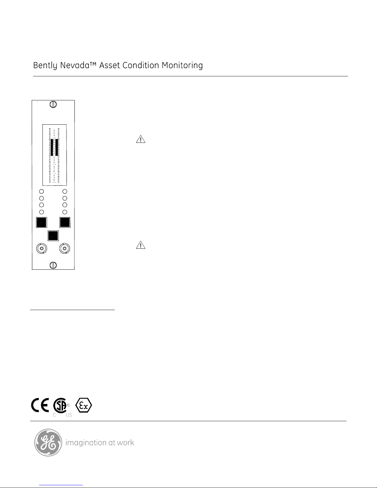
3300/20 Dual Thrust Position Monitor
BUFFERED TR ANSDUCER S
DANGER
A
GAP
ALERT
B
BYPASS
ALERT
DANGER
A B
OK
3300/20
D D
12
4 R
N
T
0 25
20
S
P
A
C
E
M
E
L
15
10
U N
T
E
C
O
8
5
I 0
R
N
25
20
T
A
10
15
U
E
N
T
O
C
M
E
E
C
0
5
S
L
P
I
vdc
16
N 20
M
S
L
I
/
5
10
15
M
O
R 20
25
24
20 N
10
5
L
/
S
I
M
15
M
R
O
25
DUAL THRUST
MONITOR
Description
The 3300/20 Dual Thrust Position Monitor provides early warning of thrust
bearing failure. It continuously measures and monitors two independent
channels of shaft axial position relative to the axial clearances within the
machine. Ideally, the axial probes are installed to observe the thrust collar
directly, so the measurement represents the position of the collar relative to the
thrust bearing clearance.
Caution
Because thrust measurements are made by observing the gap voltage of the
proximity probe used as an input, a transducer failure (gap out of range) can be
interpreted by the monitor as thrust position movement and result in a false
thrust alarm. For this reason, Bently Nevada LLC. does not recommend the use
of a single probe for thrust position applications. Instead, these applications
should use two proximity probes observing the same collar or shaft and
configure the monitor as AND voting whereby both transducers must
simultaneously reach or exceed their alarm setpoints for the monitor’s alarm
relays to actuate. This 2-out-of-2 voting scheme (also known as AND voting)
provides optimum protection against both false trips and missed trips. While the
3300/20 monitor can be programmed for either single voting (OR) or dual voting
(AND), dual voting is strongly recommended for all thrust position applications.
Caution
Probe adjustment and range is critical in this monitor for machinery protection.
Improper adjustment of the transducer may prevent the monitor from alarming
(no machinery protection). For proper adjustment, follow instructions in the
manual.
Specifications and Ordering Information
Part Number 141500-01
Rev. J (06/07)
Page 1 of 6
Page 2

Specifications
• 0 to -10 Vdc: ±1.1% of
signal, ±15 mV offset.
Inputs
Signal:
Accepts one or two proximity
probe signal inputs.
Input
Impedance:
10 k Ω.
Sensitivity:
User-programmable for 200
mV/mil (8 V/mm) or 100 mV/mil (4
V/mm).
Power:
Nominal consumption of 1.5
watts.
Signal Conditioning
Accuracy:
Within ±0.33% of full-scale
typical, ±1% maximum. All
specified at temperature of +25°C
(+77°F).
Outputs
Recorder:
User-programmable for +4 to +20
mA, 0 to -10 Vdc, or +1 to +5 Vdc.
Voltage or current outputs are
proportional to programmed
monitor full-scale. Independent
recorder outputs are provided for
each channel. Monitor operation
is unaffected by short-circuits on
recorder outputs.
Recorder
Accuracy (in
addition to
signal
conditioning
accuracy) at
+25°C (+77°F):
• +4 to +20 mA: ±0.7% of
signal, ±0.09 mA offset.
• +1 to +5 Vdc: ±1.1% of
signal, ±10 mV offset.
Output
Impedance
(voltage
outputs):
100 Ω. Minimum load resistance
is 10 k Ω.
Voltage
Compliance
(current
outputs):
0 to +12 Vdc range across load.
Load resistance is 0 to 600 Ω
when using +4 to +20 mA option.
Buffered
Transducer
Outputs:
There is one coaxial connector
per channel on the front panel
and one terminal connection per
channel on the rear panel. All are
short-circuit protected.
Output
Impedance:
100 Ω.
Transducer
Supply Voltage:
User-programmable in power
supply for -24 Vdc or -18 Vdc.
Current limited on individual
monitor circuit board.
Note: Contact your nearest sales professional if 3000 series
transducers are to be used in the monitoring system which also
uses 3300 and/or 7200 series transducers.
Alarms
Alarm
Setpoints:
Both alarms (Alert and Danger)
are bi-directional (normal and
counter), digitally adjustable from
0 to 100% of full-scale and can be
set within LCD resolution (±1.6%)
to desired level. Once set, alarms
are repeatable within 0.39% of
full-scale.
Specifications and Ordering Information
Part Number 141500-01
Rev. J (06/07)
Page 2 of 6
Page 3

Displays
Meter:
Nonmultiplexing vertical bargraph
type Liquid Crystal Display (LCD).
Individual 63 segment LCD per
channel. Probe Gap indicated on
a third, center scale. LCD also
displays error codes and monitor
ADJUST mode.
Resolution:
Within ±1.6% of monitor fullscale.
Size:
83 mm (3.25 inches), vertical
dimension.
LED Indicators
OK:
One constant ON green LED per
channel indicates OK condition of
monitor, transducers, and field
wiring. Constant OFF indicates
NOT OK condition or Channel
Bypassed (red Bypass LED will be
ON). OK LED flashing at 5 Hz
indicates error code(s) stored in
memory.
Alarm:
Two red LEDs per channel
indicate alarm status (individually
for Alert and Danger). Flashing
alarm LED indicates First Out
(independent for Alert and
Danger).
Bypass:
Two red LEDs indicate status of
Danger Bypass and Rack/
Channel Bypass functions
(individually per channel).
Environmental Limits
Operating
Temperature:
0°C to +65°C (+32°F to +150°F).
Storage
Temperature:
Relative
Humidity:
To 95%, noncondensing.
CE Mark Directives
EMC Directive
Certificate of Conformity: 158710
Low Voltage
Directive
Certificate of Conformity: 135300
Hazardous Area Approvals
CSA/NRTL/C
Class I, Div 2
Groups A, B, C, D
T4 @ Ta = +65 °C
Certification
Number
150368 – 1002151 (LR 26744)
ATEX
II 3 G
EEx nC[L] IIC
T4 @ Ta = -20°C to +60°C
When installed per document
number 132577-01.
Certification
Number
BN26744C-55A
Physical
Space
Requirements:
One rack position (any position
except 1 and 2, which are
reserved for Power Supply and
System Monitor, respectively).
Weight:
1 kg (2.2 lbs.).
-40°C to +85°C (-40°F to +185°F).
Specifications and Ordering Information
Part Number 141500-01
Rev. J (06/07)
Page 3 of 6
Page 4

Ordering Information
For spares, order the complete catalog number as
described below. This includes a front panel
assembly, monitor PWAs with sheet metal, and
appropriate relay module. This unit is optioned,
tested and ready to install in your system. Spare
relay modules can be ordered separately.
Dual Thrust Position Monitor
3300/20-AXX-BXX-CXX-DXX-EXX
Option Descriptions
A: Full-scale Range Option
0 1 25-0-25 mils
0 2 30-0-30 mils
0 3 40-0-40 mils
0 5 50-0-50 mils
0 6 75-0-75 mils
1 1 0.5-0-0.5 mm
1 2 1.0-0-1.0 mm
1 3 2.0-0-2.0 mm
B: Transducer Input Option
0 1 3300 or 7200 Proximitor®
systems, 200 mV/mil (Ranges
01, 02, 03, 11, and 12 only.)
0 2 7200 11 mm (not 3300XL)
Proximitor system, 100 mV/mil
0 3 7200 14 mm or 3300 HTPS
Proximitor systems, 100
mV/mil
0 4 3000 Proximitor® 200 mV/mil
(Transducer Output Voltage in
power supply must be set for –
18 Vdc or use power converter. Ranges 01 and 11 only.)
0 5 3300XL NSv and 3300 RAM
Proximitor Sensor, 200 mV/mil
(Ranges 01 and 11 only).
Note:
1. For 3300 XL 11mm transducers, use mod 146300-01.
2. Contact your nearest sales professional if 3000 series
transducers are to be used in a monitoring system
which also uses 3300 and/or 7200 Series transducers.
C: Alarm Relay Option
0 0 No Relays
0 1 Epoxy-sealed
0 2 Hermetically-sealed
0 3 Quad Relay (Epoxy-sealed
only)
0 4 Spare Monitor-No SIM/SIRM
Notes:
1. AND voting logic is not available with Quad Relays.
2. At least one relay module must be ordered with each
3300 System. If one common relay module per system
has been ordered, all monitors of this type must be
jumper programmed at the factory to activate a relay
bus. Order SCK (Special Configuration Kit) 157520-119
& -120 for bus one or 157520-121 & -122 for bus two.
3. Agency approval places limitations on the relay
module. Refer to the Relay Module data sheet for
information.
4. Quad Relays are not available with the Internal Safety
Barriers option.
D: Agency Approval Option
0 0 Not required
0 1 CSA/NRTL/C
0 2 ATEX self certification
Note: ATEX approval requires the monitor rack be installed in a
weatherproof housing.
E: Safety Barrier Option
0 0 None
0 1 External
0 2 Internal
Spare Relay Module Assemblies
(Order the option in parenthesis for ATEX approved
spares)
81544-01(02)
No Relays
81545-01(02)
Dual Epoxy Relays
81546-01(02)
Dual Hermetic Relays
84152-01(02)
Quad Relays
88984-01(04)
Dual Hermetic, Internal Barriers
88984-02(05)
Dual Epoxy, Internal Barriers
88984-03(06)
No Relay, Internal Barriers
Notes:
1. External Safety Barriers must be ordered separately.
Specifications and Ordering Information
Part Number 141500-01
Rev. J (06/07)
Page 4 of 6
Page 5

2. Quad Relays are not available with Internal Safety
Barriers option.
Field-programmable Options
These options are field-programmable via plug-in
jumpers.
Bold text indicates options as shipped from the
factory.
First Out Option
Enabled
Disabled
OK Mode Option
Nonlatching
Latching
Alarm Time
Delay Option
0.1 second
1 second
3 seconds
6 seconds
Alert Reset
Mode Option
Latching
Nonlatching
Danger Reset
Mode Option
Latching
Nonlatching
Alert Relay
Mode Option
Normally de-energized
Normally energized
Danger Relay
Mode Option
Normally de-energized
Normally energized
Recorder
Outputs Option
+4 to +20 mA
+1 to + 5 Vdc
0 to -10 Vdc
Danger Relay
Voting Option
AND voting for relay drive
OR voting for relay drive
Note: For Quad Relays, AND voting logic must be done externally
by wiring the contacts in series.
Normal Thrust
Direction
Option:
(programmable
per channel)
Toward probe
Away from probe
Accessories
89634-01
-24V to -18V Proximitor Power
Converter
128112
Galvanic Isolator Kit
02245002
External Barrier
02200214
Surge Protector
Specifications and Ordering Information
Part Number 141500-01
Rev. J (06/07)
Page 5 of 6
Page 6

Alert
5 5
25 0 25
20
15 E
R 4
10
O U
N
T
C 8
20
15
10
0 12
5
10
16
0
5
10
15
20
20 M R
N
O
25 vdc 24
M
15
O
N
R
20
25
C
T
N
U O
R
E
Field wiring diagram
3300/20 Dual Thrust Position Monitor
DUAL THRUST
MONITOR
M
L
S
/
D
I
S
P
L
A
C
E
M
E
N
T
OK
DANGER
A
ALERT
BYPASS
DANGER
GAP
A
BUFFERED TRANSDUCERS
3300/20
Shielded Cable
M
I
L
S
/
D
S
P
L
A
C
E
M
E
N
T
Channel A
B
ALERT
To Channel A
Recorder
B
Relay
Contacts
Proximitor
3 Conductor
Output
ALERT
Channel A
Probe
R
Channel B
Probe
CH B
CH A
PWR
COM
IN
BUF
COM
REC
Channel B
Shield (Green)
(To single earth
point ground) 4 pl.
To Channel B
Recorder Output
DANGER
NC
ARM
NO
NC
ARM
NO
Danger
Relay
Contacts
Thrust Collar
Shaft
-V
T
COM
OUTPUT
Dual Relays Shown
Quad Relays also available
Bently Nevada and Proximitor are trademarks of General Electric Company.
Copyright 1999. Bently Nevada LLC.
1631 Bently Parkway South, Minden, Nevada USA 89423
Phone: 775.782.3611 Fax: 775.215.2873
www.ge-energy.com/bently
All rights reserved.
Specifications and Ordering Information
Part Number 141500-01
Rev. J (06/07)
Page 6 of 6
 Loading...