

Page 1

GE Fanuc Automation
Computer Numerical Control Products
Series 30i/300i/300is-MODEL A
Series 31i/310i/310is-MODEL A5
Series 31i/310i/310is-MODEL A
Series 32i/320i/320is-MODEL A
Parameter Manual
GFZ-63950EN/02 June 2004
Page 2

Warnings, Cautions, and Notes
as Used in this Publication
Warning notices are used in this publication to emphasize that hazardous voltages, currents,
temperatures, or other conditions that could cause personal injury exist in this equipment or
may be associated with its use.
In situations where inattention could cause either personal injury or damage to equipment, a
Warning notice is used.
Caution notices are used where equipment might be damaged if care is not taken.
GFL-001
Warning
Caution
Note
Notes merely call attention to information that is especially significant to understanding and
operating the equipment.
This document is based on information available at the time of its publication. While efforts
have been made to be accurate, the information contained herein does not purport to cover all
details or variations in hardware or software, nor to provide for every possible contingency in
connection with installation, operation, or maintenance. Features may be described herein
which are not present in all hardware and software systems. GE Fanuc Automation assumes
no obligation of notice to holders of this document with respect to changes subsequently made.
GE Fanuc Automation makes no representation or warranty, expressed, implied, or statutory
with respect to, and assumes no responsibility for the accuracy, completeness, sufficiency, or
usefulness of the information contained herein. No warranties of merchantability or fitness for
purpose shall apply.
©Copyright 2004 GE Fanuc Automation North America, Inc.
All Rights Reserved.
Page 3
B-63950EN/02 DEFINITION OF WARNING, CAUTION, AND NOTE
DEFINITION OF WARNING, CAUTION, AND NOTE
This manual includes safety precautions for protecting the user and
preventing damage to the machine. Precautions are classified into
Warning and Caution according to their bearing on safety. Also,
supplementary information is described as a Note. Read the Warning,
Caution, and Note thoroughly before attempting to use the machine.
WARNING
Applied when there is a danger of the user being
injured or when there is a danger of both the user
being injured and the equipment being damaged if
the approved procedure is not observed.
CAUTION
Applied when there is a danger of the equipment
being damaged, if the approved procedure is not
observed.
NOTE
The Note is used to indicate supplementary
information other than Warning and Caution.
• Read this manual carefully, and store it in a safe place.
s-1
Page 4

Page 5

B-63950EN/02 PREFACE
PREFACE
Applicable models
The models covered by this manual, and their abbreviations are :
Model name Abbreviation
FANUC Series 30i-MODEL A 30i –A Series 30i
FANUC Series 300i-MODEL A 300i–A Series 300i
FANUC Series 300is-MODEL A 300is–A Series 300is
FANUC Series 31i-MODEL A 31i –A
FANUC Series 31i-MODEL A5 31i –A5
FANUC Series 310i-MODEL A 310i–A
FANUC Series 310i-MODEL A5 310i–A5
FANUC Series 310is-MODEL A 310is–A
FANUC Series 310is-MODEL A5 310is–A5
FANUC Series 32i-MODEL A 32i –A Series 32i
FANUC Series 320i-MODEL A 320i–A Series 320i
FANUC Series 320is-MODEL A 320is–A Series 320is
NOTE
1 For an explanatory purpose, the following
descriptions may be used according to the types of
path control used:
- T series: For the lathe system
- M series: For the machining center system
2 Unless otherwise noted, the model names
31i/310i/310is-A, 31i/310i/310is-A5, and
32i/320i/320is-A are collectively referred to as
30i/300i/300is. However, this convention is not
necessarily observed when item 3 below is
applicable.
3 Some functions described in this manual may not
be applied to some products.
For details, refer to the DESCRIPTIONS
(B-63942EN).
Series 31i
Series 310i
Series 310is
p-1
Page 6
PREFACE B-63950EN/02
Related manuals of
Series 30i/300i/300is- MODEL A
Series 31i/310i/310is- MODEL A
Series 31i/310i/310is- MODEL A5
Series 32i/320i/320is- MODEL A
The following table lists the manuals related to Series 30i/300i
/300is-A, Series 31i/310i /310is-A, Series 31i/310i /310is-A5, Series
32i/320i /320is-A. This manual is indicated by an asterisk(*).
Table 1 Related manuals
Manual name Specification
number
DESCRIPTIONS B-63942EN
CONNECTION MANUAL (HARDWARE) B-63943EN
CONNECTION MANUAL (FUNCTION) B-63943EN-1
USER’S MANUAL (Common to T series/M series) B-63944EN
USER’S MANUAL (T series) B-63944EN-1
USER’S MANUAL (M series) B-63944EN-2
MAINTENANCE MANUAL B-63945EN
PARAMETER MANUAL B-65950EN
Programming
Macro Compiler / Macro Executor PROGRAMMING
MANUAL
Macro Compiler OPERATOR’S MANUAL B-66264EN
C Language Executor OPERATOR’S MANUAL B-63944EN-3
PMC
PMC PROGRAMMING MANUAL B-63983EN
Network
PROFIBUS-DP Board OPERATOR’S MANUAL B-63994EN
Fast Ethernet / Fast Data Server OPERATOR’S MANUAL B-64014EN
DeviceNet Board OPERATOR’S MANUAL B-64044EN
Operation guidance function
MANUAL GUIDE i OPERATOR’S MANUAL
MANUAL GUIDE i Set-up Guidance
OPERATOR’S MANUAL
B-63943EN-2
B-63874EN
B-63874EN-1
*
p-2
Page 7

B-63950EN/02 PREFACE
Related manuals of SERVO MOTOR αis/αi series
The following table lists the manuals related to SERVO MOTOR
αis/αi series
Table 2 Related manuals
Manual name
FANUC AC SERVO MOTOR αis series
FANUC AC SERVO MOTOR αi series
DESCRIPTIONS
FANUC AC SERVO MOTOR αis series
FANUC AC SERVO MOTOR αi series
PARAMETER MANUAL
FANUC AC SPINDLE MOTOR αi series DESCRIPTIONS
FANUC AC SPINDLE MOTOR αi series
PARAMETER MANUAL
FANUC SERVO AMPLIFIER αi series DESCRIPTIONS
FANUC AC SERVO MOTOR αis series
FANUC AC SERVO MOTOR αi series
FANUC AC SPINDLE MOTOR αi series
FANUC SERVO AMPLIFIER αi series
MAINTENANCE MANUAL
Either of the following servo motors and the corresponding spindle
can be connected to the CNC covered in this manual.
• FANUC SERVO MOTOR αis series
• FANUC SERVO MOTOR αi series
This manual mainly assumes that the FANUC SERVO MOTOR αi
series of servo motor is used. For servo motor and spindle information,
refer to the manuals for the servo motor and spindle that are actually
connected.
Specification
number
B-65262EN
B-65270EN
B-65272EN
B-65280EN
B-65282EN
B-65285EN
p-3
Page 8

Page 9

B-63950EN/02 TABLE OF CONTENTS
TABLE OF CONTENTS
DEFINITION OF WARNING, CAUTION, AND NOTE .................................s-1
PREFACE....................................................................................................p-1
1 DISPLAYING PARAMETERS.................................................................1
2 SETTING PARAMETERS FROM MDI .................................................... 2
3 INPUTTING AND OUTPUTTING PARAMETERS THROUGH THE
READER/PUNCHER INTERFACE .........................................................4
3.1 OUTPUTTING PARAMETERS THROUGH THE READER/PUNCHER
INTERFACE ..................................................................................................5
3.2 INPUTTING PARAMETERS THROUGH THE READER/PUNCHER
INTERFACE ..................................................................................................6
3.3 I/O FORMATS ............................................................................................... 7
3.3.1 Keywords .................................................................................................................7
3.3.2 Inch/Metric Switching..............................................................................................8
3.3.3 Bit Format.................................................................................................................8
3.3.4 Bit Machine Group Format ......................................................................................9
3.3.5 Bit Path Format ......................................................................................................10
3.3.6 Binary Axis Format................................................................................................11
3.3.7 Bit Spindle Format .................................................................................................12
3.3.8 Byte/Word/Two-Word Format...............................................................................13
3.3.9 Byte/Word/Two-Word Machine Group Format.....................................................13
3.3.10 Byte/Word/Two-Word Path Format.......................................................................14
3.3.11 Byte/Word/Two-Word Axis Format ......................................................................14
3.3.12 Byte/Word/Two-Word Spindle Format..................................................................15
3.3.13 Real Number Format ..............................................................................................16
3.3.14 Real Number Machine Group Format....................................................................16
3.3.15 Real Number Path Format......................................................................................17
3.3.16 Real Number Axis Format......................................................................................18
3.3.17 Real Number Spindle Format.................................................................................19
3.3.18 Start and End of a Record.......................................................................................19
4 DESCRIPTION OF PARAMETERS ......................................................20
4.1 DATA TYPE................................................................................................. 20
4.2 REPRESENTATION OF PARAMETERS .................................................... 22
4.3 STANDARD PARAMETER SETTING TABLES........................................... 23
c - 1
Page 10

TABLE OF CONTENTS B-63950EN/02
4.4 PARAMETERS OF SETTING...................................................................... 25
4.5 PARAMETERS OF READER/PUNCHER INTERFACE ..............................28
4.5.1 Parameters Common to all Channels......................................................................29
4.5.2 Parameters of Channel 1 (I/O CHANNEL=0) .......................................................32
4.5.3 Parameters of Channel 1 (I/O CHANNEL=1) .......................................................33
4.5.4 Parameters of Channel 2 (I/O CHANNEL=2) .......................................................34
4.6 PARAMETERS OFPOWER MATE CNC..................................................... 35
4.7 PARAMETERS OFSYSTEM CONFIGURATION ........................................36
4.8 PARAMETERS OF AXIS CONTROL/INCREMENT SYSTEM..................... 38
4.9 PARAMETERS OF COORDINATES........................................................... 51
4.10 PARAMETERS OF STORED STROKE CHECK......................................... 58
4.11 PARAMETERS OF THE CHUCK AND TAIL STOCK BARRIER................. 62
4.12 PARAMETERS OF FEEDRATE .................................................................. 68
4.13 PARAMETERS OF ACCELERATION/DECELERATION CONTROL .......... 79
4.14 PARAMETERS OF SERVO......................................................................... 95
4.15 PARAMETERS OF DI/DO ......................................................................... 126
4.16 PARAMETERS OF DISPLAY AND EDIT (1/2)..........................................136
4.17 PARAMETERS OF PROGRAMS .............................................................. 160
4.18 PARAMETERS OF PITCH ERROR COMPENSATION ............................174
4.19 PARAMETERS OF SPINDLE CONTROL ................................................. 183
4.20 PARAMETERS OF TOOL COMPENSATION (1 OF 2)............................. 224
4.21 PARAMETERS OF CANNED CYCLES.....................................................247
4.21.1 Parameter of Canned Cycle for Drilling (1 of 2)..................................................247
4.21.2 Parameter of Thread Cutting Cycle......................................................................253
4.21.3 Parameter of Multiple Repetitive Canned Cycle..................................................254
4.21.4 Parameter of Canned Cycle for Drilling (2 of 2)..................................................260
4.22 PARAMETERS OF RIGID TAPPING ........................................................266
4.23 PARAMETERS OF SCALING/COORDINATE ROTATION ....................... 282
4.24 PARAMETERS OF SINGLE DIRECTIONAL POSITIONING.....................284
4.25 PARAMETERS OF POLAR COORDINATE INTERPOLATION ................ 285
4.26 PARAMETERS OF NORMAL DIRECTION CONTROL............................. 287
4.27 PARAMETERS OF INDEX TABLE INDEXING.......................................... 290
4.28 PARAMETERS OF INVOLUTE INTERPOLATION ................................... 293
4.29 PARAMETERS OF EXPONENTIAL INTERPOLATION ............................ 294
4.30 PARAMETERS OF STRAIGHTNESS COMPENSATION ......................... 295
4.31 PARAMETERS OF INCLINATION COMPENSATION .............................. 299
4.32 PARAMETERS OF CUSTOM MACROS................................................... 300
c - 2
Page 11

B-63950EN/02 TABLE OF CONTENTS
4.33 PARAMETERS OF SKIP FUNCTION ....................................................... 317
4.34 PARAMETERS OF EXTERNAL DATA INPUT/OUTPUT .......................... 329
4.35 PARAMETERS OF FINE TORQUE SENSING..........................................331
4.36 PARAMETERS OF GRAPHIC DISPLAY................................................... 331
4.37 PARAMETERS OF SCREEN DISPLAY COLORS (1 OF 2)...................... 332
4.38 PARAMETERS OF RUN HOUR AND PARTS COUNT DISPLAY............. 333
4.39 PARAMETERS OF TOOL LIFE MANAGEMENT (1 OF 2)........................ 337
4.40 PARAMETERS OF POSITION SWITCH FUNCTIONS............................. 338
4.41 PARAMETERS OF MANUAL OPERATION AND AUTOMATIC
OPERATION.............................................................................................. 340
4.42 PARAMETERS OF MANUAL HANDLE FEED, HANDLE
INTERRUPTION AND HANDLE FEED IN TOOL AXIAL DIRECTION ...... 343
4.43 PARAMETERS OF REFERENCE POSITION WITH MECHANICAL
STOPPER ................................................................................................. 346
4.44 PARAMETERS OF SOFTWARE OPERATOR'S PANEL.......................... 348
4.45 PARAMETERS OF PROGRAM RESTART...............................................353
4.46 PARAMETERS OF ROTARY TABLE DYNAMIC FIXTURE OFFSET ....... 354
4.47 PARAMETERS OF POLYGON TURNING ................................................ 356
4.48 PARAMETERS OF THE ELECTRIC GEAR BOX (EGB)........................... 366
4.49 PARAMETERS OF AXIS CONTROL BY PMC.......................................... 375
4.50 PARAMETERS OF MULTI-PATH CONTROL ........................................... 384
4.51 PARAMETERS OF INTERFERENCE CHECK BETWEEN PATHS .......... 387
4.52 PARAMETERS OF AXIS RECOMPOSITION AND SUPERIMPOSED
CONTROL ................................................................................................. 392
4.53 PARAMETERS OF ANGULAR AXIS CONTROL ...................................... 407
4.54 PARAMETERS OF FEED AXIS SYNCHRONOUS CONTROL................. 409
4.55 PARAMETERS OF SEQUENCE NUMBER COMPARISON AND STOP..418
4.56 PARAMETERS OF CHOPPING ................................................................ 419
4.57 PARAMETERS OF AI CONTOUR CONTROL .......................................... 422
4.58 PARAMETERS OF HIGH-SPEED POSITION SWITCH (1 OF 2) ............. 426
4.59 OTHER PARAMETERS ............................................................................ 431
4.60 PARAMETERS OF MAINTENANCE ......................................................... 434
4.61 PARAMETERS OF THE INCORRECT OPERATION PREVENTION
FUNCTION ................................................................................................ 435
4.62 PARAMETERS OF SCREEN DISPLAY COLORS (2 OF 2)...................... 446
4.63 PARAMETERS OF THREE-DIMENSIONAL ERROR
COMPENSATION3.................................................................................... 447
c - 3
Page 12

TABLE OF CONTENTS B-63950EN/02
4.64 PARAMETERS OF PMC ........................................................................... 450
4.65 PARAMETERS OF HIGH-SPEED POSITION SWITCH (2 OF 2) ............. 457
4.66 PARAMETERS OF MALFUNCTION PROTECTION................................. 459
4.67 PARAMETERS OF MANUAL HANDLE (2 OF 2) ...................................... 460
4.68 PARAMETERS OF DISPLAY AND EDIT (2 OF 2).................................... 475
4.69 PARAMETERS OF TOOL LIFE MANAGEMENT (2 OF 2)........................ 479
4.70 PARAMETERS OF THE MACHINING CONDITION SELECTION
FUNCTION ................................................................................................ 492
4.71 PARAMETER OF LINEAR SCALE WITH ABSOLUTE ADDRESS
REFERENCE POSITION .......................................................................... 499
4.72 PARAMETERS OF FSSB.......................................................................... 500
4.73 PARAMETERS OF PERIODICAL SECONDARY PITCH
COMPENSATION...................................................................................... 509
4.74 PARAMETERS OF AI CONTOUR CONTROL .......................................... 511
4.75 PARAMETERS OF CYLINDRICAL INTERPOLATION.............................. 514
4.76 PARAMETERS OF OPTIMAL TORQUE
ACCELERATION/DECELERATION .......................................................... 517
4.77 PARAMETERS OF NANO SMOOTHING.................................................. 521
4.78 PARAMETERS OF TOOL COMPENSATION (2 OF 2)............................. 522
4.79 PARAMETERS OF 5-AXIS MACHINING FUNCTION............................... 526
APPENDIX
A CHARACTER CODE LIST.................................................................. 551
c - 4
Page 13
B-63950EN/02 1.DISPLAYING PARAMETERS
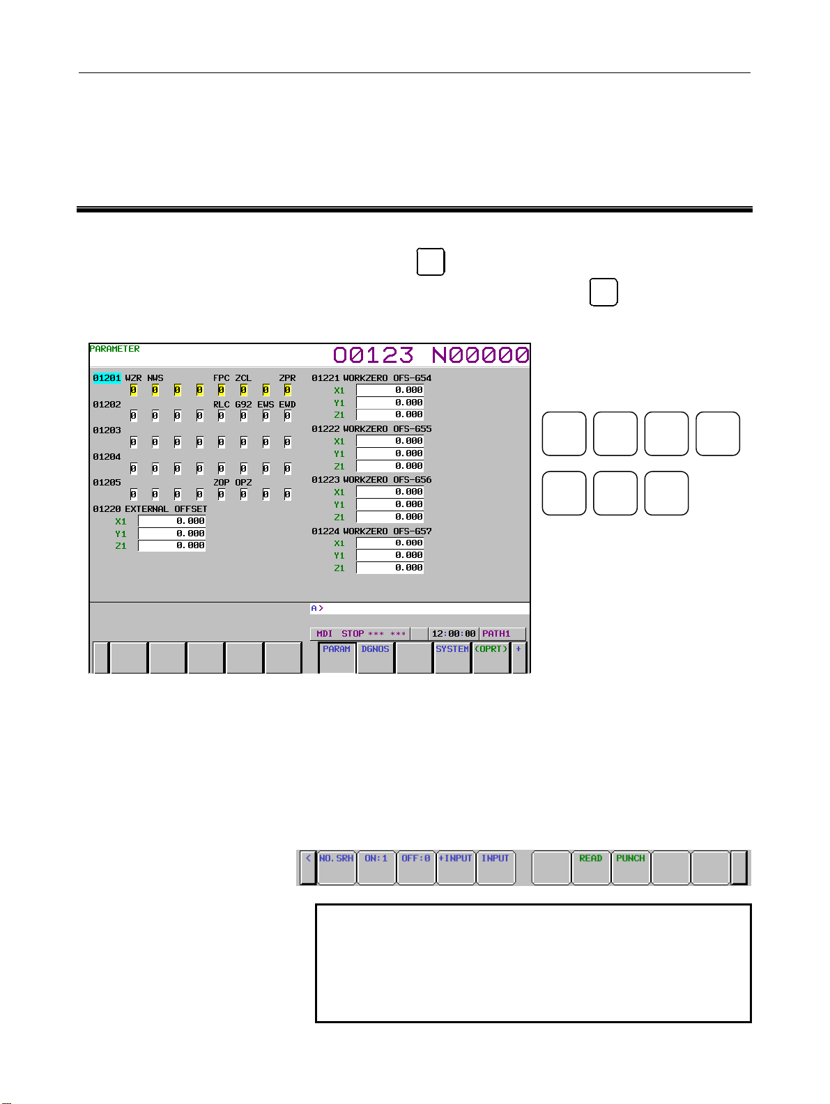
1 DISPLAYING PARAMETERS
Follow the procedure below to display parameters.
1 Press the
SYSTEM
function key on the MDI as many times as
required, or alternatively, press the
then the PARAM section display soft key. The parameter screen
is then selected.
SYSTEM MESSAGE GRAPH
2 The parameter screen consists of multiple pages. Use step (a) or
(b) to display the page that contains the parameter you want to
display.
(a) Use the page select key or the cursor move keys to display
the desired page.
(b) Enter the data number of the parameter you want to display
from the keyboard, then press the [NO.SRH] soft key. The
parameter page containing the specified data number
appears with the cursor positioned at the data number. (The
data is displayed in reverse video.)
SYSTEM
POS PROG
Function key
function key once,
OFFSET
SETTING
CUSTOM
NOTE
If key entry is started with the section select soft
keys displayed, they are replaced automatically by
operation select soft keys including [NO.SRH].
Pressing the [(OPRT)] soft key can also cause the
operation select keys to be displayed.
- 1 -
Page 14
2.SETTING PARAMETERS FROM MDI B-63950EN/02
2 SETTING PARAMETERS FROM MDI
Follow the procedure below to set parameters.
1 Place the NC in the MDI mode or the emergency stop state.
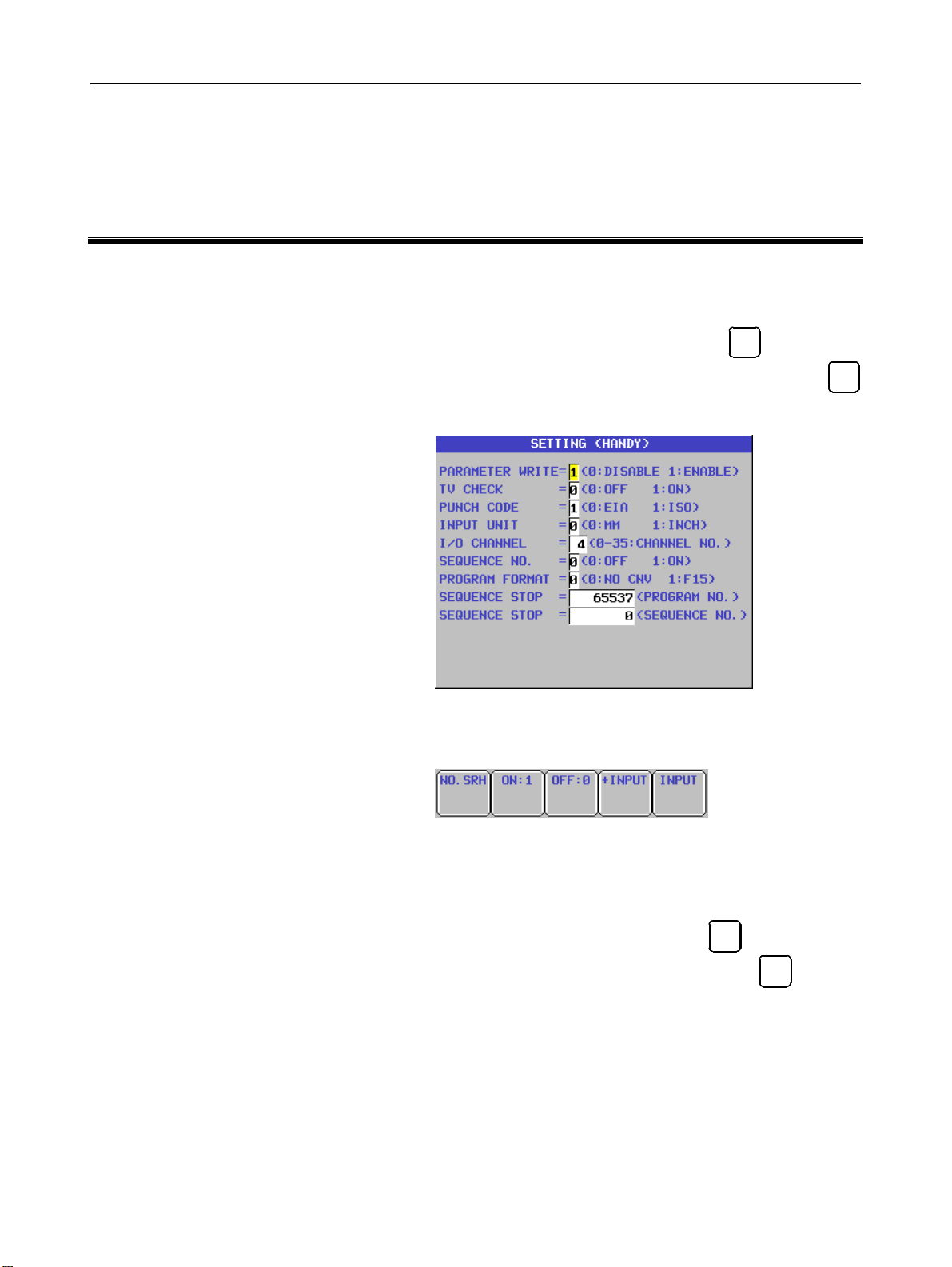
2 Follow the substeps below to enable writing of parameters.
OFFSET
SETTING
2-1 To display the setting screen, press the
as many times as required, or alternatively press the
function key once, then the [SETTING] section select soft
key. (The first page of the setting screen appears.)
function key
OFFSET
SETTING
2-2 Position the cursor on "PARAMETER WRITE" using the
cursor move keys.
2-3 Press the [(OPRT)] soft key to display operation select soft
keys.
2-4 To set "PARAMETER WRITE=" to 1, press the [ON:1]
soft key, or alternatively enter 1 and press the [INPUT] soft
key. From now on, the parameters can be set. At the
same time an alarm condition (SW0100 PARAMETER
WRITE ENABLE) occurs in the CNC.
3 To display the parameter screen, press the
many times as required, or alternatively press the
key once, then the PARAM section select soft key. (See "1.
Displaying Parameters.")
4 Display the page containing the parameter you want to set, and
position the cursor on the parameter. (See "1. Displaying
Parameters.")
5 Enter data, then press the [INPUT] soft key. The parameter
indicated by the cursor is set to the entered data.
SYSTEM
function key as
SYSTEM
function
- 2 -
Page 15
B-63950EN/02 2.SETTING PARAMETERS FROM MDI
[Example] 12000 [INPUT]
Data can be entered continuously for parameters, starting at the
selected parameter, by separating each data item with a
semicolon (;).
[Example] Entering 10;20;30;40 and pressing the INPUT key assigns
values 10, 20, 30, and 40 to parameters in order starting at
the parameter indicated by the cursor.
6 Repeat steps (4) and (5) as required.
7 If parameter setting is complete, set "PARAMETER WRITE="
to 0 on the setting screen to disable further parameter setting.
8 Reset the NC to release the alarm condition (SW0100).
If an alarm condition (PW0000 PLEASE TURN OFF POWER)
occurs in the NC, turn it off before continuing operation.
- 3 -
Page 16

3.INPUTTING AND OUTPUTTING PARAMETERS THROUGH THE READER/PUNCHER INTERFACE B-63950EN/02
3 INPUTTING AND OUTPUTTING
PARAMETERS THROUGH THE
READER/PUNCHER INTERFACE
This section explains the parameter input/output procedures for
input/output devices connected to the reader/puncher interface.
The following description assumes the input/output devices are ready
for input/output. It also assumes parameters peculiar to the
input/output devices, such as the baud rate and the number of stop bits,
have been set in advance. (See Section 4.5.)
- 4 -
Page 17
B-63950EN/02 3.INPUTTING AND OUTPUTTING PARAMETERS THROUGH THE READER/PUNCHER INTERFACE
3.1 OUTPUTTING PARAMETERS THROUGH THE
READER/PUNCHER INTERFACE
1 Select the EDIT mode or set to Emergency stop.
2 To select the parameter screen, press the
SYSTEM
function key as
many times as required, or alternatively press the
SYSTEM
function
key once, then the PARAM section select soft key.
3 Press the [(OPRT)] soft key to display operation select soft keys,
then press the forward menu key located at the right-hand side of
the soft keys to display another set of operation select keys
including [PUNCH].
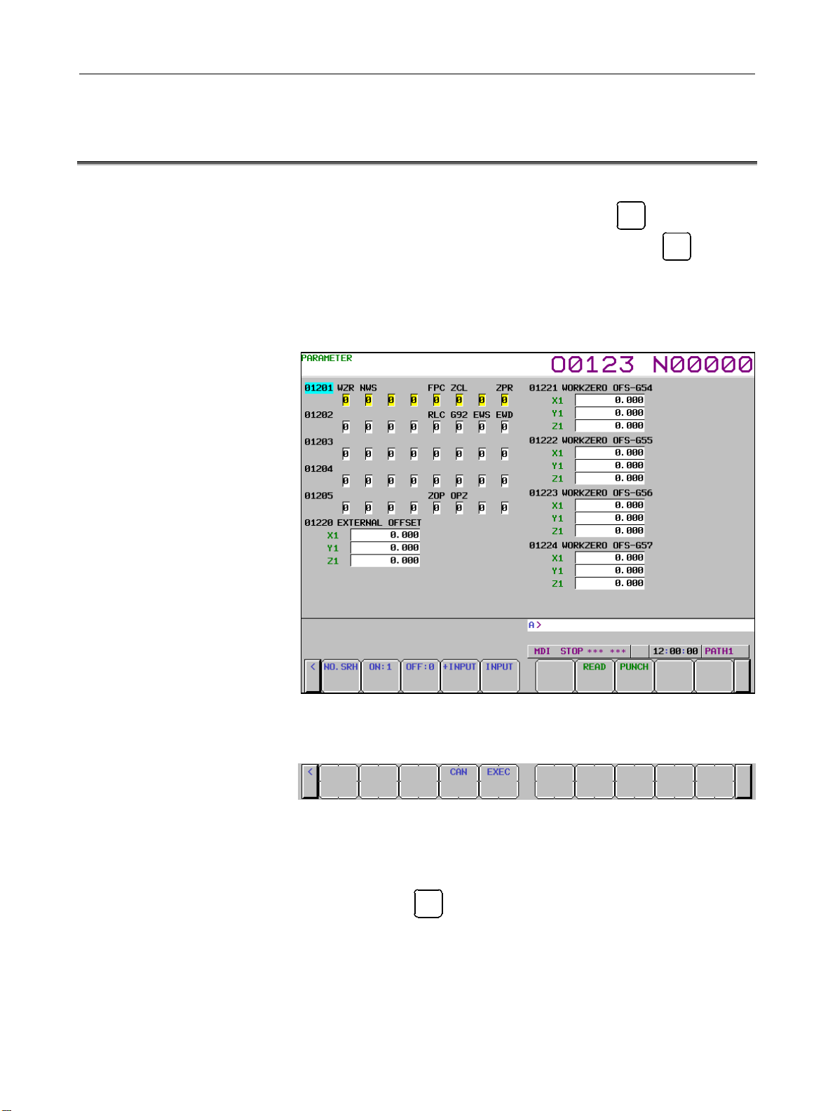
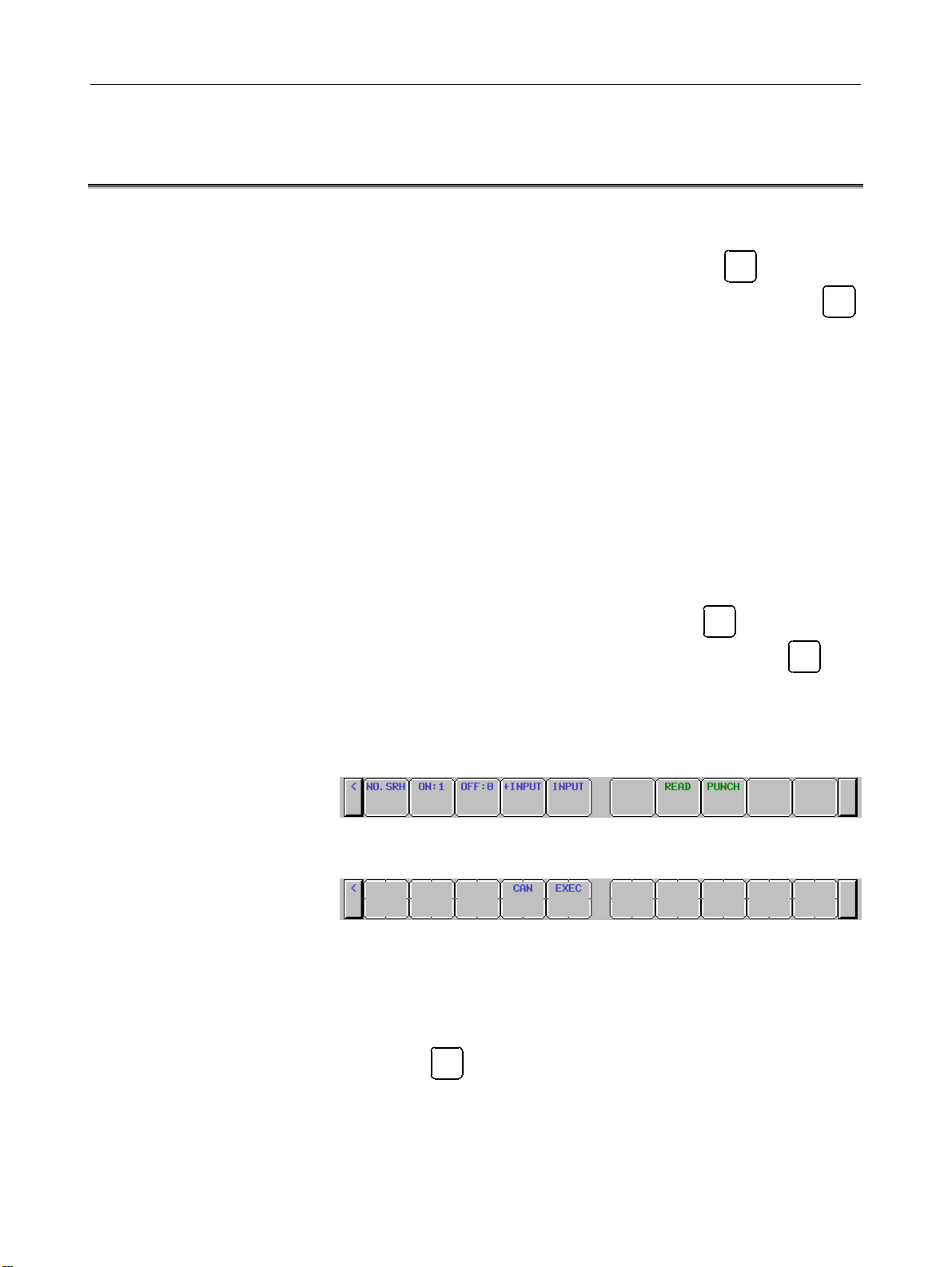
4 Pressing the [PUNCH] soft key changes the soft key display as
shown below:
5 Press the [EXEC] soft key to start parameter output. When
parameters are being output, "PNCH" blinks in the state display
field on the lower part of the screen.
6 When parameter output terminates, "PNCH" stops blinking.
RESET
Press the
key to interrupt parameter output.
- 5 -
Page 18
3.INPUTTING AND OUTPUTTING PARAMETERS THROUGH THE READER/PUNCHER INTERFACE B-63950EN/02
3.2 INPUTTING PARAMETERS THROUGH THE
READER/PUNCHER INTERFACE
1 Place the NC in the emergency stop state.
2 Enable parameter writing.
OFFSET
SETTING
2-1 To display the setting screen, press the
as many times as required, or alternatively press the
function key once, then the [SETING] section select soft
key. The first page of the setting screen appears.
2-2 Position the cursor on "PARAMETER WRITE" using the
cursor move keys.
2-3 Press the [(OPRT)] soft key to display operation select soft
keys.
2-4 To set "PARAMETER WRITE=" to 1, press the [ON:1]
soft key, or alternatively enter 1, then press the [INPUT]
soft key. From now on, parameters can be set.
At the same time an alarm condition (SW0100
PARAMETER WRITE ENABLE) occurs in the NC.
3 To select the parameter screen, press the
SYSTEM
function key
OFFSET
SETTING
function key as
many times as required, or alternatively press the
SYSTEM
key
once, then [PARAM] soft key.
4 Press the [(OPRT)] soft key to display operation select keys, then
press the forward menu key located at the right-hand side of the
soft keys to display another set of operation select soft keys
including [READ].
5 Pressing the [READ] soft key changes the soft key display as
shown below:
6 Press the [EXEC] soft key to start inputting parameters from the
input/output device. When parameters are being input,
"READ" blinks in the state display field on the lower part of the
screen.
7 When parameter input terminates, "READ" stops blinking. Press
RESET
the
key to interrupt parameter input.
8 When parameter read terminates, "INPUT" stops blinking, and
an alarm condition (PW0100) occurs in the NC. Turn it off
before continuing operation.
- 6 -
Page 19
B-63950EN/02 3.INPUTTING AND OUTPUTTING PARAMETERS THROUGH THE READER/PUNCHER INTERFACE
3.3 I/O FORMATS
This section describes the I/O formats of parameters.
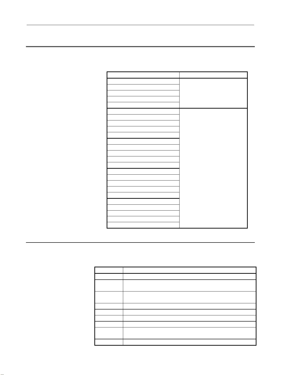
Parameters are classified by data format as follows:
Data format Remarks
3.3.1 Keywords
Bit
Bit machine group
Bit path
Bit axis
Bit spindle
Byte
Byte machine group
Byte path
Byte axis
Byte spindle
Word
Word machine group
Word path
Word axis
Word spindle
2-word
2-word machine group
2-word path
2-word axis
2-word spindle
Real
Real machine group
Real path
Real axis
Real spindle
The alphabetic characters listed below are used as keywords.
A numeric value after each keyword has the following meaning:
Keyword Meaning of a numeric value that follows
N Parameter number
Q Data identifier (1: Parameter data, 0: Pitch error compensation
data)
T
L
A Controlled axis number (1 and up) of an axis type parameter
S Spindle number (1 and up) of a spindle type parameter
P Value of a parameter independent of inch/metric switching
M Metric input value of a parameter dependent on inch/metric
I Inch input value of a parameter dependent on inch/metric switching
Machine group number (1 and up) of a machine group type
parameter
Path number (1 and up) of a path type parameter
switching
Data of these formats is
represented by an 8-digit binary
number, with each digit
corresponding to a bit.
The setting range of data varies
from one parameter to another.
For details, refer to the
description of each parameter.
- 7 -
Page 20

3.INPUTTING AND OUTPUTTING PARAMETERS THROUGH THE READER/PUNCHER INTERFACE B-63950EN/02
3.3.2 Inch/Metric Switching
For parameters dependent on inch/metric switching such as those for
length and feedrate, whether data is inch data or metric data is
specified by the input mode in the case of input from the MDI panel,
or by the keyword I or M prefixed to the data in the case of input from
an external I/O device. The keyword I or M is added also when data
is output from an external I/O device.
If the input mode or keyword differs from the actually used mode as
in a case where data input in the inch mode is used in the metric mode,
the CNC performs automatic data conversion. So, data need not be
converted according to a mode change. Moreover, when parameter
data is displayed, the data is converted according to the display mode.
However, when data is output from an external I/O device, the original
data is output according to the original keyword.
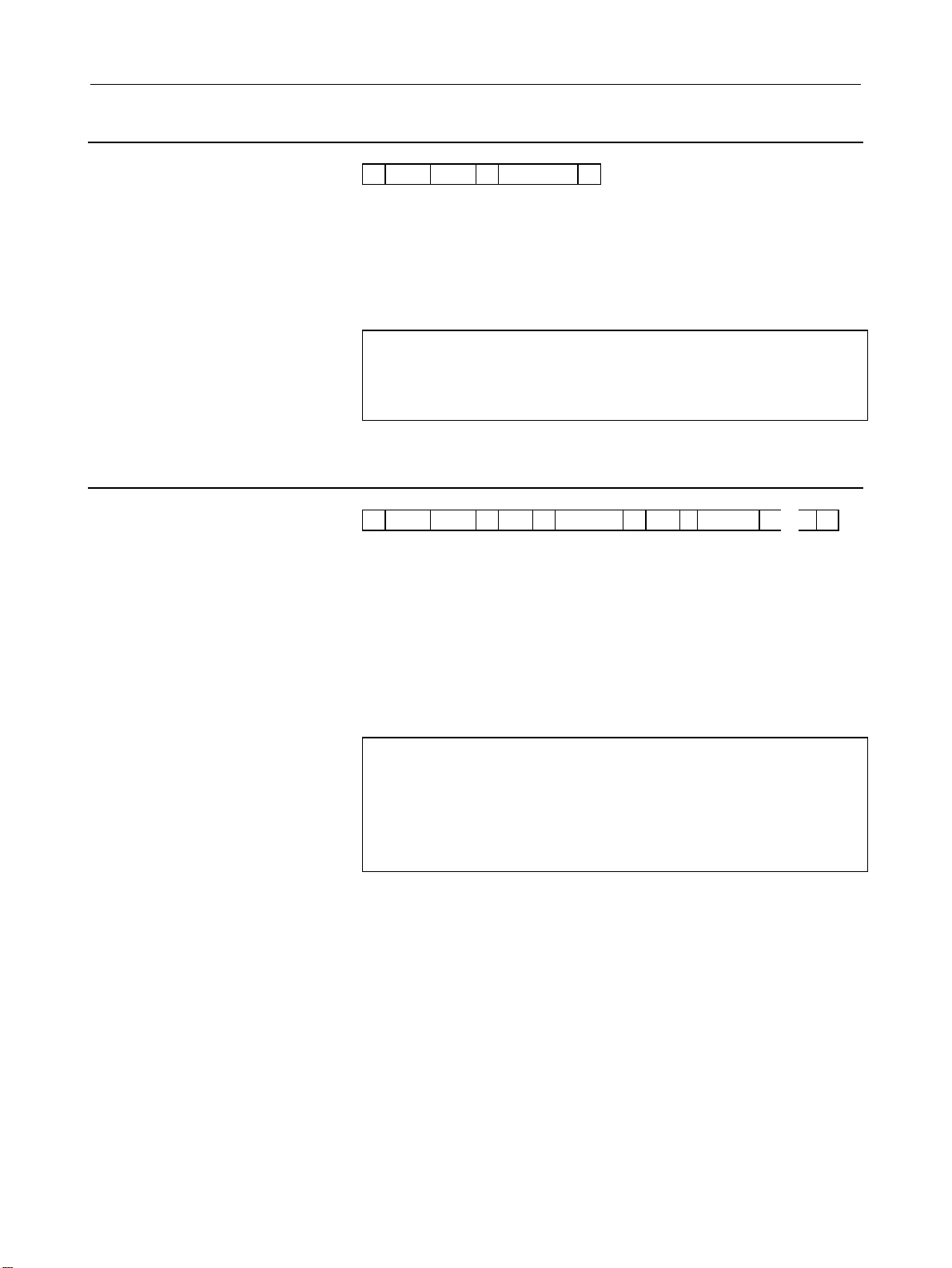
3.3.3 Bit Format
N ***** Q1 P ******** ;
A numeric value after N represents a parameter number.
Q1 indicates that the data is parameter data.
An 8-digit binary number after P represents the bit values (0/1) of a
parameter, with the first digit corresponding to bit 0 and the eighth
digit corresponding to bit 7.
Leading zeros may not be omitted.
A semicolon (;) marks the end of a block. (LF is used for the ISO
code, and CR is used for the EIA code.)
Example
N00010Q1P00000001;
Parameter No. 10
Parameter value
Bit 0 is set to 1, and the other bits are set to 0.
- 8 -
Page 21

B-63950EN/02 3.INPUTTING AND OUTPUTTING PARAMETERS THROUGH THE READER/PUNCHER INTERFACE
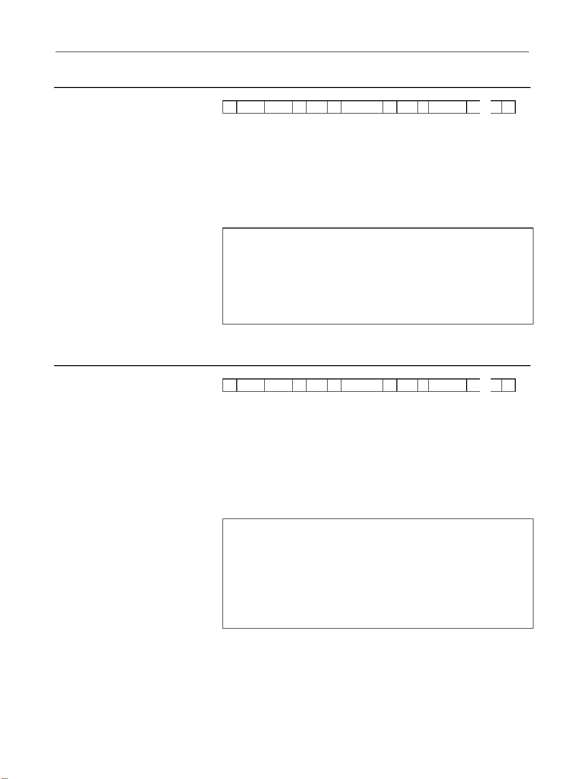
3.3.4 Bit Machine Group Format
N ***** Q1 T ** P ******** T ** P ********
A numeric value after N represents a parameter number.
Q1 indicates that the data is parameter data.
A numeric value after T represents a machine group number (1 and
up).
An 8-digit binary number after P represents the bit values (0/1) of a
parameter for each machine group, with the first digit corresponding
to bit 0 and the eighth digit corresponding to bit 7.
Leading zeros may not be omitted.
A semicolon (;) marks the end of a block. (LF is used for the ISO
code, and CR is used for the EIA code.)
Example
N01005Q1T1P10000001T2P10000001 ;
Parameter No. 1005
Parameter value
1st machine group:
Bits 0 and 7 are set to 1, and the other bits are
set to 0.
2nd machine group:
Bits 0 and 7 are set to 1, and the other bits are
set to 0.
・ ・ ・
;
- 9 -
Page 22

3.INPUTTING AND OUTPUTTING PARAMETERS THROUGH THE READER/PUNCHER INTERFACE B-63950EN/02
3.3.5 Bit Path Format
N ***** Q1 L ** P ******** L ** P ********
A numeric value after N represents a parameter number.
Q1 indicates that the data is parameter data.
A numeric value after L represents a path number (1 and up).
An 8-digit binary number after P represents the bit values (0/1) of a
parameter for each path, with the first digit corresponding to bit 0 and
the eighth digit corresponding to bit 7.
Leading zeros may not be omitted.
A semicolon (;) marks the end of a block. (LF is used for the ISO
code, and CR is used for the EIA code.)
Example
N01005Q1L1P10000001L2P10000001.......;
Parameter No. 1005
Parameter value
Path 1:
Bits 0 and 7 are set to 1, and the other bits are
set to 0.
Path 2:
Bits 0 and 7 are set to 1, and the other bits are
set to 0.
・ ・ ・
;
- 10 -
Page 23

B-63950EN/02 3.INPUTTING AND OUTPUTTING PARAMETERS THROUGH THE READER/PUNCHER INTERFACE
3.3.6 Binary Axis Format
N ***** Q1 A ** P ******** A ** P ********
A numeric value after N represents a parameter number.
Q1 indicates that the data is parameter data.
A numeric value after A represents a controlled axis number (1 and
up).
An 8-digit binary number after P represents the bit values (0/1) of a
parameter for each controlled axis, with the first digit corresponding
to bit 0 and the eighth digit corresponding to bit 7.
Leading zeros may not be omitted.
A semicolon (;) marks the end of a block. (LF is used for the ISO
code, and CR is used for the EIA code.)
Example
N01005Q1A1P10000001A2P10000001A3P10000001.......;
Parameter No. 1005
Parameter value
1st axis:
Bits 0 and 7 are set to 1, and the other bits are set to 0.
2nd axis:
Bits 0 and 7 are set to 1, and the other bits are set to 0.
3rd axis:
Bits 0 and 7 are set to 1, and the other bits are set to 0.
▪
・ ・ ・
;
- 11 -
Page 24

3.INPUTTING AND OUTPUTTING PARAMETERS THROUGH THE READER/PUNCHER INTERFACE B-63950EN/02
3.3.7 Bit Spindle Format
N ***** Q1 S ** P ******** S ** P ********
A numeric value after N represents a parameter number.
Q1 indicates that the data is parameter data.
A numeric value after S represents a spindle number (1 and up).
An 8-digit binary number after P represents the bit values (0/1) of a
parameter for each spindle, with the first digit corresponding to bit 0
and the eighth digit corresponding to bit 7.
Leading zeros may not be omitted.
A semicolon (;) marks the end of a block. (LF is used for the ISO
code, and CR is used for the EIA code.)
Example
N05603Q1S1P00001000S2P00001000S3P00000000;
Parameter No. 5603
Parameter value
1st spindle:
Bit 3 is set to 1, and the other bits are set to 0.
2nd spindle:
Bit 3 is set to 1, and the other bits are set to 0.
3rd spindle:
All bits are set to 0.
・ ・ ・
;
- 12 -
Page 25
B-63950EN/02 3.INPUTTING AND OUTPUTTING PARAMETERS THROUGH THE READER/PUNCHER INTERFACE
3.3.8 Byte/Word/Two-Word Format
N ***** Q1 P ******** ;
A numeric value after N represents a parameter number.
Q1 indicates that the data is parameter data.
A numeric value after P represents a parameter value (integer).
A semicolon (;) marks the end of a block. (LF is used for the ISO
code, and CR is used for the EIA code.)
Example
N00100Q1P31515;
Parameter No. 100
Parameter value 31515
3.3.9 Byte/Word/Two-Word Machine Group Format
N ***** Q1 T ** P ****** T ** P******
A numeric value after N represents a parameter number.
Q1 indicates that the data is parameter data.
A numeric value after T represents a machine group number (1 and
up).
A numeric value after P represents the value (integer) of a parameter
for each machine group.
A semicolon (;) marks the end of a block. (LF is used for the ISO
code, and CR is used for the EIA code.)
Example
N01020Q1T1P88T2P89......;
Parameter No. 1020
Parameter value 1st machine group: 88
2nd machine group: 89
▪
・ ・ ・
;
- 13 -
Page 26
3.INPUTTING AND OUTPUTTING PARAMETERS THROUGH THE READER/PUNCHER INTERFACE B-63950EN/02
3.3.10 Byte/Word/Two-Word Path Format
N ***** Q1 L ** P ****** L ** P******
A numeric value after N represents a parameter number.
Q1 indicates that the data is parameter data.
A numeric value after L represents a path number (1 and up).
A numeric value after P represents the value (integer) of a parameter
for each path.
A semicolon (;) marks the end of a block. (LF is used for the ISO
code, and CR is used for the EIA code.)
・ ・ ・
;
Example
N01020Q1L1P88L2P89L3P90......;
Parameter No. 1020
Parameter value Path 1: 88
Path 2: 89
Path 3: 90
▪
3.3.11 Byte/Word/Two-Word Axis Format
N ***** Q1 A ** P ****** A ** P******
A numeric value after N represents a parameter number.
Q1 indicates that the data is parameter data.
A numeric value after A represents a controlled axis number (1 and
up).
A numeric value after P represents the value (integer) of a parameter
for each controlled axis.
A semicolon (;) marks the end of a block. (LF is used for the ISO
code, and CR is used for the EIA code.)
Example
N01020Q1A1P88A2P89A3P90A4P66......;
Parameter No. 1020
Parameter value 1st axis: 88
2nd axis: 89
3rd axis: 90
4th axis: 66
▪
・ ・ ・
;
- 14 -
Page 27

B-63950EN/02 3.INPUTTING AND OUTPUTTING PARAMETERS THROUGH THE READER/PUNCHER INTERFACE
3.3.12 Byte/Word/Two-Word Spindle Format
N ***** Q1 S ** P ****** S ** P******
A numeric value after N represents a parameter number.
Q1 indicates that the data is parameter data.
A numeric value after S represents a spindle number (1 and up).
A numeric value after P represents the value (integer) of a parameter
for each spindle.
A semicolon (;) marks the end of a block. (LF is used for the ISO
code, and CR is used for the EIA code.)
Example
N05680Q1S1P19S2P19S3P0S4P0;
Parameter No. 5680
Parameter value 1st spindle: 19
2nd spindle: 19
3rd spindle: 0
4th spindle: 0
・ ・ ・
;
- 15 -
Page 28
3.INPUTTING AND OUTPUTTING PARAMETERS THROUGH THE READER/PUNCHER INTERFACE B-63950EN/02
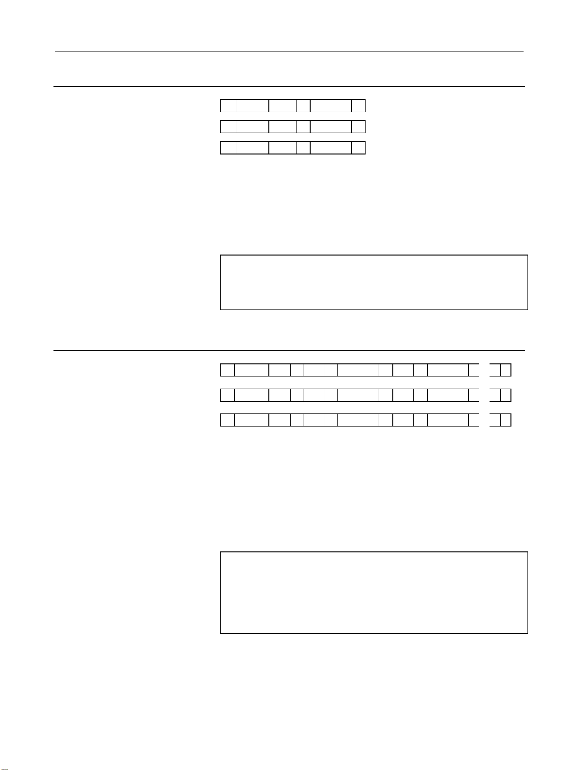
3.3.13 Real Number Format
N ***** Q1 P ****** ;
N ***** Q1 M ****** ;
N ***** Q1 I ****** ;
A numeric value after N represents a parameter number.
Q1 indicates that the data is parameter data.
A numeric value after each of P, M, and I represents the value (real
number) of a parameter.
A semicolon (;) marks the end of a block. (LF is used for the ISO
code, and CR is used for the EIA code.)
Example
N01451Q1P5000.0;
Parameter No. 1451
Parameter value 5000.0
3.3.14 Real Number Machine Group Format
N ***** Q1 T ** P ****** T ** P ******
N ***** Q1 T ** M ****** T ** M ******
N ***** Q1 T ** I ****** T ** I ******
A numeric value after N represents a parameter number.
Q1 indicates that the data is parameter data.
A numeric value after T represents a machine group number (1 and
up).
A numeric value after each of P, M, and I represents the value (real
number) of a parameter for each machine group.
A semicolon (;) marks the end of a block. (LF is used for the ISO
code, and CR is used for the EIA code.)
Example
N01220Q1T1M50.0T2M60.0........;
Parameter No. 1220
Parameter value 1st machine group: 50.0
2nd machine group: 60.0
▪
・ ・ ・
・ ・ ・
・ ・ ・
;
;
;
- 16 -
Page 29

B-63950EN/02 3.INPUTTING AND OUTPUTTING PARAMETERS THROUGH THE READER/PUNCHER INTERFACE
3.3.15 Real Number Path Format
N ***** Q1 L ** P ****** L ** P ******
N ***** Q1 L ** M ****** L ** M ******
N ***** Q1 L ** I ****** L ** I ******
A numeric value after N represents a parameter number.
Q1 indicates that the data is parameter data.
A numeric value after L represents a path number (1 and up).
A numeric value after each of P, M, and I represents the value (real
number) of a parameter for each path.
A semicolon (;) marks the end of a block. (LF is used for the ISO
code, and CR is used for the EIA code.)
Example
N01220Q1L1M50.0L2M60.0L3M70.0 ;
Parameter No. 1220
Parameter value Path 1: 50.0
Path 2: 60.0
Path 3: 70.0
・ ・ ・
・ ・ ・
・ ・ ・
;
;
;
- 17 -
Page 30

3.INPUTTING AND OUTPUTTING PARAMETERS THROUGH THE READER/PUNCHER INTERFACE B-63950EN/02
3.3.16 Real Number Axis Format
N ***** Q1 A ** P ****** A ** P ******
N ***** Q1 A ** M ****** A ** M ******
N ***** Q1 A ** I ****** A ** I ******
A numeric value after N represents a parameter number.
Q1 indicates that the data is parameter data.
A numeric value after A represents a controlled axis number (1 and
up).
A numeric value after each of P, M, and I represents the value (real
number) of a parameter for each controlled axis.
A semicolon (;) marks the end of a block. (LF is used for the ISO
code, and CR is used for the EIA code.)
Example
N01220Q1A1M50.0A2M60.0A3M70.0A4M0.0A5M0
.0 ........;
Parameter No. 1220
Parameter value 1st axis: 50.0
2nd axis: 60.0
3rd axis: 70.0
4th axis: 0.0
5th axis: 0.0
▪
・ ・ ・
・ ・ ・
・ ・ ・
;
;
;
- 18 -
Page 31

B-63950EN/02 3.INPUTTING AND OUTPUTTING PARAMETERS THROUGH THE READER/PUNCHER INTERFACE
3.3.17 Real Number Spindle Format
N ***** Q1 S ** P ****** S ** P ******
N ***** Q1 S ** M ****** S ** M ******
N ***** Q1 S ** I ****** S ** I ******
A numeric value after N represents a parameter number.
Q1 indicates that the data is parameter data.
A numeric value after S represents a spindle number (1 and up).
A numeric value after each of P, M, and I represents the value (real
number) of a parameter for each spindle.
A semicolon (;) marks the end of a block. (LF is used for the ISO
code, and CR is used for the EIA code.)
・ ・ ・
・ ・ ・
・ ・ ・
;
;
;
Example
N05898Q1S1P30.0S2P30.0S3P0.0S4P0.0;
Parameter No. 5898
Parameter value 1st spindle: 30.0
2nd spindle: 30.0
3rd spindle: 0.0
4th spindle: 0.0
3.3.18 Start and End of a Record
A parameter record starts with "%" and ends with "%".
Example
%; ..........................................Start of record
N00000Q1P00001100;
N00002Q1P00000000;
▪
▪
N09162Q1P00000000;
N09163Q1P00000000;
% ...........................................End of record
When parameters and pitch error compensation data are included in a
single file, the file starts with "%" and ends with "%".
- 19 -
Page 32

4.DESCRIPTION OF PARAMETERS B-63950EN/02
4 DESCRIPTION OF PARAMETERS
4.1 DATA TYPE
Parameters are classified by data type as follows:
Data type Valid data range Remarks
Bit
Bit machine group
Bit path
Bit axis
Bit spindle
Byte
Byte machine group
Byte path
Byte axis
Byte spindle
Word
Word machine group
Word path
Word axis
Word spindle
2-word
2-word machine group
2-word path
2-word axis
2-word spindle
Real
Real machine group
Real path
Real axis
Real spindle
0 or 1
-128 to 127
0 to 255
-32768 to 32767
0 to 65535
0 to ±999999999
See the Standard
Parameter Setting
Tables.
Some parameters handle
these types of data as
unsigned data.
Some parameters handle
these types of data as
unsigned data.
Some parameters handle
these types of data as
unsigned data.
- 20 -
Page 33

B-63950EN/02 4.DESCRIPTION OF PARAMETERS
NOTE
1 Each of the parameters of the bit, bit machine
group, bit path, bit axis, and bit spindle types
consists of 8 bits for one data number (parameters
with eight different meanings).
2 For machine group types, parameters
corresponding to the maximum number of machine
groups are present, so that independent data can
be set for each machine group.
3 For path types, parameters corresponding to the
maximum number of paths are present, so that
independent data can be set for each path.
4 For axis types, parameters corresponding to the
maximum number of control axes are present, so
that independent data can be set for each control
axis.
5 For spindle types, parameters corresponding to the
maximum number of spindles are present, so that
independent data can be set for each spindle axis.
6 The valid data range for each data type indicates a
general range. The range varies according to the
parameters. For the valid data range of a specific
parameter, see the explanation of the parameter.
- 21 -
Page 34

4.DESCRIPTION OF PARAMETERS B-63950EN/02
4.2 REPRESENTATION OF PARAMETERS
Parameters of the bit type, bit machine group type, bit path type, bit axis type,
and bit spindle type
#7 #6 #5 #4 #3 #2 #1 #0
0000 EIA NCR ISP CTV TVC
Data No. Data (Data #0 to #7 are bit positions.)
Parameters other than the bit-type parameters above
1023 Number of the servo axis for each axis
Data No. Data
NOTE
1 The bits left blank in 4. DESCRIPTION OF PARAMETERS and parameter numbers
that appear on the display but are not found in the parameter list are reserved for
future expansion. They must always be 0.
2 A parameter usable with only one path control type, namely, the lathe system (T
series) or the machining center system (M series), is indicated using two rows as
shown below. When a row is blank, the parameter is not usable with the
corresponding series.
[Example 1]
Parameter HTG is a parameter common to the M and T series, but Parameters RTV
and ROC are parameters valid only for the T series.
#7 #6
1403
RTV
[Example 2]
The following parameter is provided only for the M series.
1411
3 When "to" is inserted between two parameter numbers, there are parameters with
successive numbers between the two starting and ending parameter numbers, but
those intermediate parameter numbers are omitted for convenience.
4 The lower-case letter "x" or "s" following the name of a bit-type parameter indicates
the following:
- ”
- ”
x” : Bit axis type parameters
s” : Bit spindle type parameters
#5 #4 #3 #2 #1 #0
ROC
HTG
HTG
Cutting feedrate
T series
M series
T series
M series
- 22 -
Page 35

B-63950EN/02 4.DESCRIPTION OF PARAMETERS
4.3 STANDARD PARAMETER SETTING TABLES
Overview
This section defines the standard minimum data units and valid data
ranges of the CNC parameters of the real type, real machine group
type, real path type, real axis type, and real spindle type. The data type
and unit of data of each parameter conform to the specifications of
each function.
Explanation
(A) Length and angle parameters (type 1)
Unit of data
mm
deg.
inch
Increment
system
IS-A 0.01 -999999.99 to +999999.99
IS-B 0.001 -999999.999 to +999999.999
IS-C 0.0001 -99999.9999 to +99999.9999
IS-D 0.00001 -9999.99999 to +9999.99999
IS-E 0.000001 -999.999999 to +999.999999
IS-A 0.001 -99999.999 to +99999.999
IS-B 0.0001 -99999.9999 to +99999.9999
IS-C 0.00001 -9999.99999 to +9999.99999
IS-D 0.000001 -999.999999 to +999.999999
IS-E 0.0000001 -99.9999999 to +99.9999999
(B) Length and angle parameters (type 2)
Unit of data
mm
deg.
inch
Increment
system
IS-A 0.01 0.00 to +999999.99
IS-B 0.001 0.000 to +999999.999
IS-C 0.0001 0.0000 to +99999.9999
IS-D 0.00001 0.00000 to +9999.99999
IS-E 0.000001 0.000000 to +999.999999
IS-A 0.001 0.000 to +99999.999
IS-B 0.0001 0.0000 to +99999.9999
IS-C 0.00001 0.00000 to +9999.99999
IS-D 0.000001 0.000000 to +999.999999
IS-E 0.0000001 0.0000000 to +99.9999999
Minimum
data unit
Minimum
data unit
Valid data range
Valid data range
- 23 -
Page 36

4.DESCRIPTION OF PARAMETERS B-63950EN/02
(C) Velocity and angular velocity parameters
Unit of data
mm/min
degree/min
inch/min
Increment
system
IS-A 0.01 0.0 to +999000.00
IS-B 0.001 0.0 to +999000.000
IS-C 0.0001 0.0 to +99999.9999
IS-D 0.00001 0.0 to +9999.99999
IS-E 0.000001 0.0 to +999.999999
IS-A 0.001 0.0 to +96000.000
IS-B 0.0001 0.0 to +9600.0000
IS-C 0.00001 0.0 to +4000.00000
IS-D 0.000001 0.0 to +400.000000
IS-E 0.0000001 0.0 to +40.0000000
Minimum
data unit
Valid data range
(D)Acceleration and angular acceleration parameters
Unit of data
mm/sec2
deg./sec
inch/sec2
2
Increment
system
IS-A 0.01 0.00 to +999999.99
IS-B 0.001 0.000 to +999999.999
IS-C 0.0001 0.0000 to +99999.9999
IS-D 0.00001 0.00000 to +9999.99999
IS-E 0.000001 0.000000 to +999.999999
IS-A 0.001 0.000 to +99999.999
IS-B 0.0001 0.0000 to +99999.9999
IS-C 0.00001 0.00000 to +9999.99999
IS-D 0.000001 0.000000 to +999.999999
IS-E 0.0000001 0.0000000 to +99.9999999
Minimum
data unit
Valid data range
Notes
(1) Values are rounded up or down to the nearest multiples of the
minimum data unit.
(2) A valid data range means data input limits, and may differ from
values representing actual performance.
(3) For information on the ranges of commands to the CNC, refer to
Appendix, "List of Command Ranges," in the "USER’S
MANUAL" (B-63944EN).
- 24 -
Page 37

B-63950EN/02 4.DESCRIPTION OF PARAMETERS
4.4 PARAMETERS OF SETTING
#7 #6 #5 #4 #3 #2 #1 #0
0000 SEQ INI ISO TVC
[Input type] Setting input
[Data type] Bit path
# 0 TVC TV check
0: Not performed
1: Performed
# 1 ISO Code used for data output
0: EIA code
1: ISO code
NOTE
ASCII code is used at all times for output to the
memory card.
# 2 INI Unit of input
0: In metrics
1: In inches
# 5 SEQ Automatic insertion of sequence numbers
0: Not performed
1: Performed
- 25 -
Page 38

4.DESCRIPTION OF PARAMETERS B-63950EN/02
#7 #6 #5 #4 #3 #2 #1 #0
0001 FCV
[Input type] Setting input
[Data type] Bit path
# 1 FCV Program format
0: Series 16 standard format
1: Series 15 format
NOTE
1 Programs created in the Series 15 program format
can be used for operation on the following
functions:
1 Subprogram call M98
2 Thread cutting with equal leads G32 (T series)
3 Canned cycle G90, G92, G94 (T series)
4 Multiple repetitive canned cycle G71 to G76 (T
series)
5 Drilling canned cycle
G83.1, G80 to G89 (T series)
G73, G74, G76, G80 to G89(M series)
2 When the program format used in the Series 15 is
used for this CNC, some limits may add. Refer to
the User’s Manual.
#7 #6 #5 #4 #3 #2 #1 #0
0002 SJZ
[Input type] Setting input
[Data type] Bit
# 7 SJZ On an axis for which bit 3 (HJZx) of parameter No. 1005 is set:
0: If a reference position is not established yet, reference position
return is performed with deceleration dogs.
If a reference position is already established, reference position
return is performed at a parameter-set feedrate without using
deceleration dogs.
1: Reference position return is performed with deceleration dogs at
all times.
NOTE
SJZ is valid for an axis for which bit 3 (HJZx) of
parameter No. 1005 is set to 1. When bit 1
(DLZx) of parameter No. 1005 is set to 1, however,
manual reference position return after a reference
position is set is performed at a parameter-set
feedrate, regardless of the setting of SJZ.
- 26 -
Page 39

B-63950EN/02 4.DESCRIPTION OF PARAMETERS
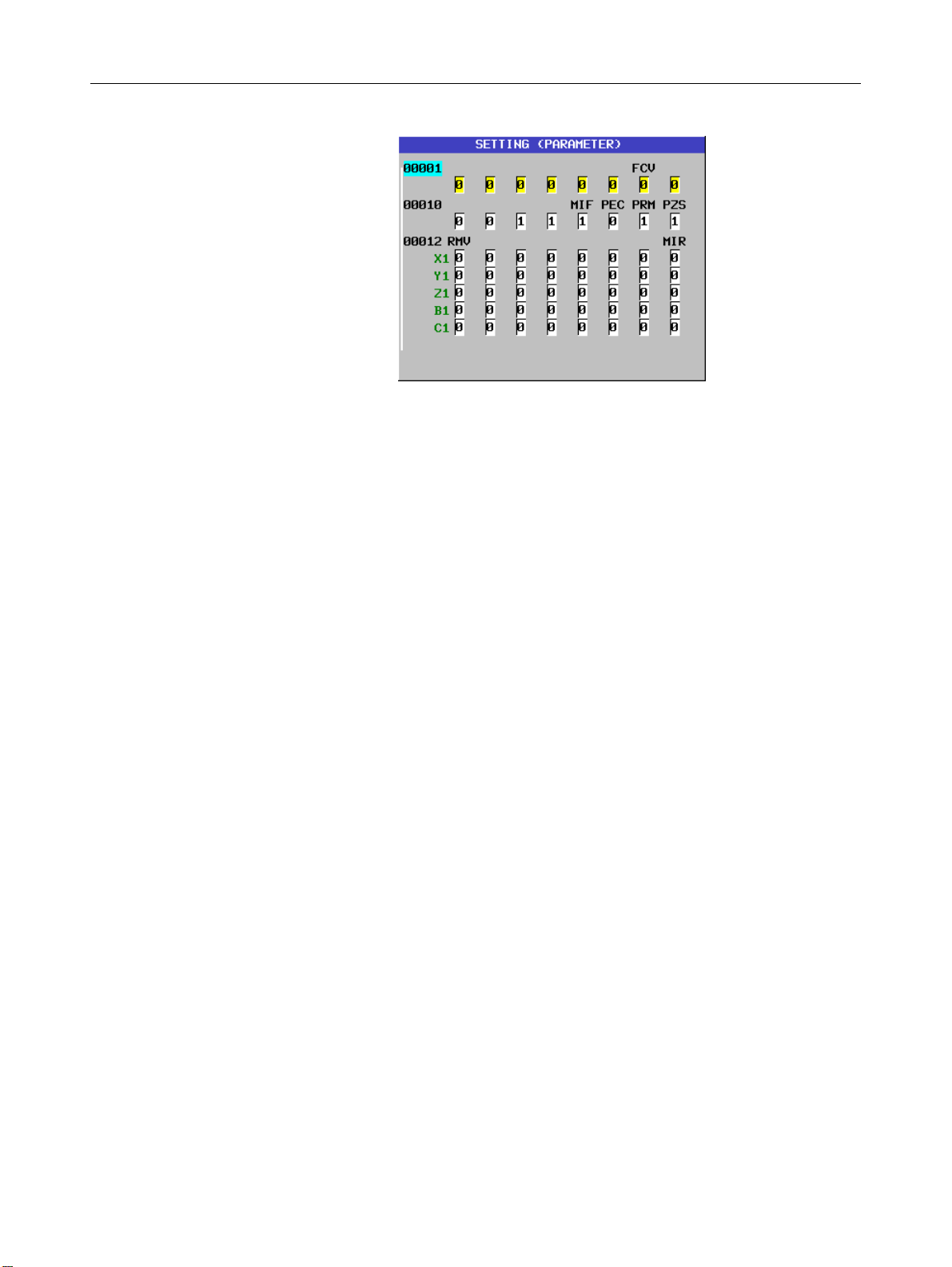
#7 #6 #5 #4 #3 #2 #1 #0
0010 PEC PRM PZS
[Input type] Setting input
[Data type] Bit path
# 0 PZS When a part program is punched out, the O number is:
0: Not zero-suppressed.
1: Zero-suppressed.
# 1 PRM When parameters are output, the parameters whose values are 0 are:
0: Output.
1: Not output.
# 2 PEC When pitch error compensation data is output, the data whose value is
0 is:
0: Output.
1: Not output.
NOTE
This parameter is invalid for output of
high-precision pitch error compensation data.
#7 #6 #5 #4 #3 #2 #1 #0
0012 RMVx MIRx
[Input type] Setting input
[Data type] Bit axis
# 0 MIRx Mirror image for each axis
0: Mirror image is off. (Normal)
1: Mirror image is on. (Mirror)
# 7 RMVx Releasing the assignment of the control axis for each axis
0: Not released
1: Released
(Equivalent to the control axis detachment signals DTCH1, DTCH2,
and so forth)
NOTE
RMVx is valid when bit 7 (RMBx) of parameter No.
1005 is set to 1.
- 27 -
Page 40

4.DESCRIPTION OF PARAMETERS B-63950EN/02
y
4.5 PARAMETERS OF READER/PUNCHER INTERFACE
To transfer data (programs, parameters, and so forth) to and from an
external input/output device through the I/O device interface
(RS-232-C serial interface), the parameters described below need to
be set.
The input/output device connected to a channel (such as RS-232-C
serial port 1 and RS-232-C serial port 2) can be selected by setting I/O
CHANNEL (parameter No. 0020). The specifications (input/output
specification number, baud rate, and the number of stop bits) of an
input/output device connected to each channel must be set in the
parameters corresponding to each channel beforehand.
For channel 1, two combinations of parameters to specify the
input/output device data are provided.
The following shows the interrelation between the input/output device
interface parameters for the channels.
I/O CHANNEL
0020
or foreground input
Set channels to be used
for data input/output.
I/O CHANNEL (0 to 5)
=0 : Channel 1
=1 : Channel 1
=2 : Channel 2
=3 : Channel 3
:
:
:
Input/output to and from the memor
card interface, etc. is also possible.
When IO4 is set
0021
Foreground output
0022
Background input
0023
Background input
The channel setting is the same as
No.0020.
Input/output channel number (parameter No.0020)
↓
0101 Stop bit and other data
I/O CHANNEL=0 0102 Number specified for the input/output device
(Channel 1)
I/O CHANNEL=1 0112 Number specified for the input/output device
(Channel 1)
I/O CHANNEL=2 0122 Number specified for the input/output device
(Channel 2)
:
:
:
I/O CHANNEL=5
0103 Baud rate
0111 Stop bit and other data
0113 Baud rate
0121 Stop bit and other data
0123 Baud rate
- 28 -
Page 41

B-63950EN/02 4.DESCRIPTION OF PARAMETERS
4.5.1 Parameters Common to all Channels
0020
0021 Foreground output device setting
0022 Background input device setting
0023 Background output device setting
[Input type] Setting input
[Data type] Byte
[Valid data range] 0 to 5
I/O CHANNEL : Input/output device selection, or interface number for a
foreground input device
The CNC has the following interfaces for transferring data to and from
an external input/output device and the host computer:
Input/output device interface (RS-232-C serial ports 1 and 2)
Memory card interface
Data server interface
By setting bit 0 (IO4) of parameter No. 0110, data input/output can be
controlled separately. When IO4 is not set, data input/output is
performed using the channel set in parameter No. 0020. When IO4
is set, a channel can be assigned to each of foreground input,
foreground output, background input, and background output.
In these parameters, specify the interface connected to each
input/output device to and from which data is to be transferred. See
the table below for these settings.
Correspondence between settings and input/output devices
Setting Description
0,1 RS-232-C serial port 1
2 RS-232-C serial port 2
4 Memory card interface
5 Data server interface
- 29 -
Page 42

4.DESCRIPTION OF PARAMETERS B-63950EN/02
0024
Setting of communication with the ladder development tool (FANUC
LADDER-III, ladder editing package)
[Input type] Setting input
[Data type] Word
[Valid data range] 0 to 255
This parameter is used to enable or disable the PMC online connection
function.
By specifying this parameter, the PMC online connection function can
be enabled or disabled without displaying the PMC online setting
screen.
Setting RS-232-C High-speed interface
0 The setting on the PMC online setting screen is not altered.
1 To be used (channel 1) Not to be used
2 To be used (channel 2) Not to be used
10 Not to be used To be used
11 To be used (channel 1) To be used
12 To be used (channel 2) To be used
255 Communication is terminated forcibly (as with the [FORCED
STOP] soft key).
NOTE
1 The setting of this parameter becomes valid when
the power is turned on or this parameter is
modified. After this parameter is set, the power
need not be turned off then back on.
2 A setting modification made on the PMC online
setting screen is not reflected in this parameter.
3 The communication settings of a baud rate and so
forth for using RS-232-C made on the PMC online
setting screen are valid. When no modification is
ever made to the settings on the PMC online
setting screen, the baud rate is 9600, parity is not
used, and the number of stops bits is 2.
#7 #6 #5 #4 #3 #2 #1 #0
0100 ENS IOP NCR CRF CTV
[Input type] Setting input
[Data type] Bit
# 1 CTV Character counting for TV check in the comment section of a
program.
0: Performed
1: Not performed
# 2 CRF Output of the end of block (EOB) in ISO code
0: Depends on the setting of bit 3 (NCR) of parameter No. 100.
1: CR, LF are output.
- 30 -
Page 43

B-63950EN/02 4.DESCRIPTION OF PARAMETERS
# 3 NCR Output of the end of block (EOB) in ISO code
0: LF, CR, CR are output.
1: Only LF is output.
# 6 IOP Stopping a program output or input operation by a reset is:
0: Enabled
1: Disabled
(Stopping a program input/output operation with the [STOP] soft key
is enabled at all times.)
# 7 ENS Action taken when a NULL code is found during read of EIA code
0: An alarm is generated.
1: The NULL code is ignored.
#7 #6 #5 #4 #3 #2 #1 #0
0110 IO4
[Input type] Parameter input
[Data type] Bit
NOTE
When this parameter is set, the power must be
turned off before operation is continued.
# 0 IO4 Separate control of I/O channel numbers is:
0: Not performed.
1: Performed.
If the I/O channels are not separately controlled, set the input/output
device in parameter No. 20.
If the I/O channels are separately controlled, set the input device and
output device in the foreground and the input device and output device
in the background in parameters No. 20 to No. 23 respectively.
Separate control of I/O channels makes it possible to perform
background editing, program input/output, and the like during the
DNC operation.
#7 #6 #5 #4 #3 #2 #1 #0
0138 MNC
[Input type] Parameter input
[Data type] Bit
# 7 MNC DNC operation from the memory card and external device
subprogram call from the memory card are:
0: Not performed.
1: Performed.
- 31 -
Page 44

4.DESCRIPTION OF PARAMETERS B-63950EN/02
4.5.2 Parameters of Channel 1 (I/O CHANNEL=0)
#7 #6 #5 #4 #3 #2 #1 #0
0101 NFD ASI SB2
[Input type] Parameter input
[Data type] Bit
# 0 SB2 The number of stop bits
0: 1
1: 2
# 3 ASI Code used at data input
0: EIA or ISO code (automatically distinguished)
1: ASCII code
# 7 NFD Feed before and after the data at data output
0: Output
1: Not output
When input/output devices other than the FANUC PPR are used, set
NFD to 1.
0102
[Input type] Parameter input
[Data type] Byte
[Valid data range] 0 to 6
0103 Baud rate (when I/O CHNNEL is set to 0)
[Input type] Parameter input
[Data type] Byte
[Valid data range] 1 to 12
Number specified for the input/output device (when the I/O CHANNEL is set
to 0)
Set the specification number of the input/output device corresponding
to I/O CHANNEL=0.
Set the baud rate of the input/output device corresponding to I/O
CHANNEL=0.
- 32 -
Page 45

B-63950EN/02 4.DESCRIPTION OF PARAMETERS
4.5.3 Parameters of Channel 1 (I/O CHANNEL=1)
#7 #6 #5 #4 #3 #2 #1 #0
0111 NFD ASI SB2
[Input type] Parameter input
[Data type] Bit
# 0 SB2 The number of stop bits
0: 1
1: 2
# 3 ASI Code used at data input
0: EIA or ISO code (automatically distinguished)
1: ASCII code
# 7 NFD Feed before and after the data at data output
0: Output
1: Not output
0112
[Input type] Parameter input
[Data type] Byte
[Valid data range] 0 to 6
0113 Baud rate (when I/O CHNNEL is set to 1)
[Input type] Parameter input
[Data type] Byte
[Valid data range] 1 to 12
Number specified for the input/output device (when the I/O CHANNEL is set
to 1)
Set the specification number of the input/output device corresponding
to I/O CHANNEL=1.
Set the baud rate of the input/output device corresponding to I/O
CHANNEL=1.
- 33 -
Page 46

4.DESCRIPTION OF PARAMETERS B-63950EN/02
4.5.4 Parameters of Channel 2 (I/O CHANNEL=2)
#7 #6 #5 #4 #3 #2 #1 #0
0121 NFD ASI SB2
[Input type] Parameter input
[Data type] Bit
# 0 SB2 The number of stop bits
0: 1
1: 2
# 3 ASI Code used at data input
0: EIA or ISO code (automatically distinguished)
1: ASCII code
# 7 NFD Feed before and after the data at data output
0: Output
1: Not output
When input/output devices other than the FANUC PPR are used, set
NFD to 1.
0122
[Input type] Parameter input
[Data type] Byte
[Valid data range] 0 to 6
0123 Baud rate (when I/O CHNNEL is set to 2)
[Input type] Parameter input
[Data type] Byte
[Valid data range] 1 to 12
Number specified for the input/output device (when the I/O CHANNEL is set
to 2)
Set the specification number of the input/output device corresponding
to I/O CHANNEL=2.
Set the baud rate of the input/output device corresponding to I/O
CHANNEL=2.
- 34 -
Page 47

B-63950EN/02 4.DESCRIPTION OF PARAMETERS
4.6 PARAMETERS OF POWER MATE CNC
#7 #6 #5 #4 #3 #2 #1 #0
0960 PPE PMN MD2 MD1
[Input type] Parameter input
[Data type] Bit path
# 1 MD1 The input/output destination of slave parameters is:
0: Program memory (when MD2 = 0)
1: Memory card (when MD2 = 0)
# 2 MD2 The input/output destination of slave parameters is as follows:
0: Be sure to set MD2 to 0. (The destination is determined by
MD1 and MD2.)
1: Reserved
Parameter MD2 Parameter MD1 I/O destination
0 0 Program memory
0 1 Memory card
# 3 PMN The Power Mate CNC manager function is:
0: Enabled.
1: Disabled.
This parameter is used to place priority on commands from the ladder
for each connected slave (to stop communication by the Power Mate
CNC manager function) after completion of setting and confirmation
of necessary data with each slave.
# 4 PPE
0: The Power Mate CNC manager can set slave parameters at all
times.
1: Slave parameter setting by the Power Mate CNC manager
follows the setting of PWE for the host CNC. When PWE = 0,
the setting of the I/O LINK β parameter is prohibited.
#7 #6 #5 #4 #3 #2 #1 #0
0961 PMO
[Input type] Parameter input
[Data type] Bit
# 3 PMO The O number of a program for saving and restoring the I/O LINK β
parameter is set based on:
0: Group number and channel number
1: Group number only
- 35 -
Page 48

4.DESCRIPTION OF PARAMETERS B-63950EN/02
4.7 PARAMETERS OFSYSTEM CONFIGURATION
0980 Machine group number to which each path belongs
NOTE
When this parameter is set, the power must be
turned off before operation is continued.
[Input type] Parameter input
[Data type] Byte path
[Valid data range] 1 to 3
Set the machine group number to which each path belongs.
NOTE
When 0 is set, each path is assumed to belong to
machine group 1.
0981 Absolute path number to which each axis belongs
NOTE
When this parameter is set, the power must be
turned off before operation is continued.
[Input type] Parameter input
[Data type] Byte axis
[Valid data range] 1 to 10
Set the path to which each axis belongs.
NOTE
When 0 is set, each axis is assumed to belong to
path 1.
0982 Absolute path number to which each spindle belongs
NOTE
When this parameter is set, the power must be
turned off before operation is continued.
[Input type] Parameter input
[Data type] Byte spindle
[Valid data range] 1 to 10
Set the path to which each spindle belongs.
NOTE
When 0 is set, each axis is assumed to belong to
path 1.
- 36 -
Page 49

B-63950EN/02 4.DESCRIPTION OF PARAMETERS
0983 Path control type of each path
NOTE
When this parameter is set, the power must be
turned off before operation is continued.
[Input type] Parameter input
[Data type] Byte path
[Valid data range] 0 to 1
Set the path control type of each path.
The following two path control types are available:
T series (lathe system) : 0
M series (machining system) : 1
#7 #6 #5 #4 #3 #2 #1 #0
0984 LCP
[Input type] Parameter input
[Data type] Bit path
NOTE
When this parameter is set, the power must be
turned off before operation is continued.
# 0 LCP Set whether the path is a loader control path.
0: The path is not a loader control path.
1: The path is a loader control path.
- 37 -
Page 50

4.DESCRIPTION OF PARAMETERS B-63950EN/02
4.8 PARAMETERS OF AXIS CONTROL/INCREMENT SYSTEM
#7 #6 #5 #4 #3 #2 #1 #0
1000 EEA
[Input type] Parameter input
[Data type] Bit
# 0 EEA An extended axis name and extended spindle name are:
0: Invalid
1: Valid
#7 #6 #5 #4 #3 #2 #1 #0
1001 INM
[Input type] Parameter input
[Data type] Bit path
NOTE
When this parameter is set, the power must be
turned off before operation is continued.
# 0 INM Least command increment on the linear axis
0: In mm (metric system machine)
1: In inches (inch system machine)
#7 #6 #5 #4 #3 #2 #1 #0
1002 IDG XIK AZR JAX
[Input type] Parameter input
[Data type] Bit path
# 0 JAX Number of axes controlled simultaneously in jog feed, manual rapid
traverse and manual reference position return
0: 1 axis
1: 3 axes
# 3 AZR When no reference position is set, the G28 command causes:
0: Reference position return using deceleration dogs (as during
manual reference position return) to be executed.
1: Alarm (PS0304) "G28 was specified when no reference position
is set" to be displayed.
NOTE
When reference position return without dogs is
specified, (when bit 1 (DLZ) of parameter No.1002 is
set to 1) the G28 command specified before a
reference position is set causes an alarm PS0304 to
be issued, regardless of the setting of AZR.
- 38 -
Page 51

B-63950EN/02 4.DESCRIPTION OF PARAMETERS
# 4 XIK When LRP, bit 1 of parameter No.1401, is set to 0, namely, when
positioning is performed using non-linear type positioning, if an
interlock is applied to the machine along one of axes in positioning,
0: The machine stops moving along the axis for which the interlock
is applied and continues to move along the other axes.
1: The machine stops moving along all the axes.
# 7 IDG When the reference position is set without dogs, automatic setting of
the IDGx parameter (bit 0 of parameter No.1012) to prevent the
reference position from being set again is:
0: Not performed.
1: Performed.
NOTE
When this parameter is set to 0, bit 0 (IDGx) of
parameter No. 1012 is invalid.
#7 #6 #5 #4 #3 #2 #1 #0
1004 IPR
[Input type] Parameter input
[Data type] Bit path
# 7 IPR When a number with no decimal point is specified, the least input
increment of each axis is:
0: Not 10 times greater than the least command increment
1: 10 times greater than the least command increment
When the increment system is IS-A, and bit 0 (DPI) of parameter No.
3401 is set to 1 (fixed-point format), the least input increment cannot
be 10 times greater than the least command increment.
- 39 -
Page 52

4.DESCRIPTION OF PARAMETERS B-63950EN/02
#7 #6 #5 #4 #3 #2 #1 #0
1005 RMBx MCCx EDMx EDPx HJZx DLZx ZRNx
[Input type] Parameter input
[Data type] Bit axis
# 0 ZRNx If a move command other than G28 is specified by automatic
operation when no reference position return is performed yet after the
power is turned on:
0: The alarm (PS0224) "PERFORM REFERENCE POSITION
RETURN." is issued.
1: Operation is performed without issuing an alarm.
NOTE
The state in which a reference position has not been
established refers to the following state:
- When an absolute position detector is not used
and reference position return has not been
performed even once after power-up
- When an absolute position detector is used and
the association of the machine position with the
position detected with the absolute position
detector has not been completed (See the
description of bit 4 (APZx) of parameter No.
1815.)
# 1 DLZx Function for setting the reference position without dogs
0: Disabled
1: Enabled
# 3 HJZx When a reference position is already set:
0: Manual reference position return is performed with deceleration
dogs.
1: Manual reference position return is performed using rapid
traverse without deceleration dogs, or manual reference position
return is performed with deceleration dogs, depending on the
setting of bit 7 (SJZ) of parameter No.0002.
When the function for setting the reference position without dogs (see
the description of bit 1 (DLZx) of parameter No. 1005) is used,
manual reference position return after a reference position is set is
always performed at a parameter-set feedrate, regardless of the setting
of HJZ.
# 4 EDPx In cutting feed, an external deceleration signal in the + direction for
each axis is:
0: Invalid
1: Valid
# 5 EDMx In cutting feed, an external deceleration signal in the - direction for
each axis is:
0: Invalid
- 40 -
Page 53

B-63950EN/02 4.DESCRIPTION OF PARAMETERS
1: Valid
# 6 MCCx If a multi-axis amplifier is used, and another axis of the same
amplifier is placed in the control axis detach state, the MCC signal of
the servo amplifier is:
0: Turned off.
1: Not turned off.
NOTE
1 This parameter can be set for a control axis.
2 If the servo motor of an axis subject to control axis
detachment is connected to a multi-axis amplifier
such as 2-axis amplifier, and one axis is placed in
the control axis detach state, servo alarm (SV0401)
(V ready off) is issued on another axis. This alarm
can be prevented by setting this parameter.
# 7 RMBx The control axis detachment signal for each axis and the setting input
RMV (bit 7 of parameter No. 0012) are:
0: Invalid
1: Valid
#7 #6 #5 #4 #3 #2 #1 #0
1006 ZMIx DIAx ROSx ROTx
[Input type] Parameter input
[Data type] Bit axis
NOTE
When this parameter is set, the power must be
turned off before operation is continued.
ROTx, ROSx Setting linear or rotation axis.
ROSx ROTx Meaning
0 0
0 1
1 1
Except for the above. Setting is invalid (unused)
Linear axis
(1) Inch/metric conversion is done.
(2) All coordinate values are linear axis type. (Is not rounded in 0 to 360°)
(3) Stored pitch error compensation is linear axis type (Refer to parameter No.3624)
Rotation axis (A type)
(1) Inch/metric conversion is not done.
(2) Machine coordinate values are rounded in 0 to 360_. Absolute coordinate values are rounded or not
rounded by parameter No.1008#0(ROAx) and #2(RRLx).
(3) Stored pitch error compensation is the rotation type. (Refer to parameter No.3624)
(4) Automatic reference position return (G28, G30) is done in the reference position return direction and the
move amount does not exceed one rotation.
Rotation axis (B type)
(1) Inch/metric conversion, absolute coordinate values and relative coordinate values are not done.
(2) Machine coordinate values, absolute coordinate values and relative coordinate values are linear axis
type. (Is not rounded in 0 to 360°).
(3) Stored pitch error compensation is linear axis type (Refer to parameter No.3624)
(4) Cannot be used with the rotation axis roll over function and the index table indexing function (M series)
# 3 DIAx The move command for each axis is based on:
0: Radius specification
- 41 -
Page 54

4.DESCRIPTION OF PARAMETERS B-63950EN/02
1: Diameter specification
# 5 ZMIx The direction of manual reference position return is:
0: + direction
1: - direction
#7 #6 #5 #4 #3 #2 #1 #0
1007 G90x GRDx RAAx ALZx RTLx
[Input type] Parameter input
[Data type] Bit axis
# 0 RTLx When manual reference position return is performed on a rotation axis
(A type) with the deceleration dog pressed before a reference position
is established:
0: A movement is made at the reference position return feedrate FL.
1: Until a servo motor grid is established, a movement is not made
at the reference position return feedrate FL even if the
deceleration dog is pressed, but a movement is made at the rapid
traverse rate.
If the deceleration dog is released after a movement at the rapid
traverse rate and the deceleration dog is then pressed again and
released after the rotation axis makes one revolution, reference
position return operation is completed.
When this parameter is set to 0, the alarm (SW0090) "REFERENCE
POSITION RETURN FAILURE" is issued if the deceleration dog is
released before a servo motor grid is established.
If this alarm is issued, start manual reference position return at a
position sufficiently far away from the reference position.
# 1 ALZx In automatic reference position return (G28):
0: Reference position return is performed by positioning (rapid
traverse).
If no reference position return is performed after the power is
turned on, however, reference position return is performed using
the same sequence as for manual reference position return.
1: Reference position return is performed using the same sequence
as for manual reference position return.
# 3 RAAx Rotary axis control is:
0: Not exercised.
1: Exercised.
When an absolute command is specified, the rotary axis control
function determines the direction of rotation from the sign of the
command value and determines an end coordinate from the absolute
value of the command value.
- 42 -
Page 55

B-63950EN/02 4.DESCRIPTION OF PARAMETERS
NOTE
RAA is valid when bit 0 (ROA) of parameter No. 1008
is set to 1 and bit 1 (RAB) of parameter No. 1008 is
set to 0.
To use this function, the option for rotary axis control
is required.
# 4 GRDx For the axis on which absolute values are detected, when
correspondence between the machine position and the position by the
absolute position detector is not completed, setting of the reference
position without dogs is:
0: Not performed two or more times.
1: Performed two or more times.
# 5 G90x A command for a rotary controlled axis is:
0: Regarded as an absolute/incremental command according to the
G90/G91 mode setting.
1: Regarded as an absolute command at all times.
#7 #6 #5 #4 #3 #2 #1 #0
1008 RMCx SFDx RRLx RABx ROAx
[Input type] Parameter input
[Data type] Bit axis
NOTE
When this parameter is set, the power must be
turned off before operation is continued.
# 0 ROAx The roll-over function of a rotation axis is
0: Invalid
1: Valid
NOTE
ROAx specifies the function only for a rotation axis
(for which ROTx, #0 of parameter No.1006, is set to
1)
# 1 RABx In the absolute commands, the axis rotates in the direction
0: In which the distance to the target is shorter.
1: Specified by the sign of command value.
NOTE
RABx is valid only when ROAx is 1.
# 2 RRLx Relative coordinates are
0: Not rounded by the amount of the shift per one rotation
1: Rounded by the amount of the shift per one rotation
- 43 -
Page 56

4.DESCRIPTION OF PARAMETERS B-63950EN/02
NOTE
1 RRLx is valid only when ROAx is 1.
2 Assign the amount of the shift per one rotation in
parameter No.1260.
# 4 SFDx In reference position return based on the grid method, the reference
position shift function is:
0: Disabled
1: Enabled
# 5 RMCx When machine coordinate system selection (G53) is specified, bit 1
(RABx) of parameter No. 1008 for determining the rotation direction
of an absolute command for the roll-over function of a rotation axis,
and bit 3 (RAAx) of parameter No. 1007 for rotary axis control are:
0: Invalid
1: Valid
- 44 -
Page 57

B-63950EN/02 4.DESCRIPTION OF PARAMETERS
#7 #6 #5 #4 #3 #2 #1 #0
1012 IDGx
[Input type] Parameter input
[Data type] Bit axis
# 0 IDGx The function for setting the reference position again, without dogs, is:
0: Not inhibited.
1: Inhibited.
(The alarm (PS0301) is issued.)
NOTE
IDGx is enabled when the IDG parameter (bit 7 of
parameter No.1002) is 1.
If the function for setting the reference position
without dogs is used, and the reference position is
lost in absolute position detection for a cause, the
alarm (DS0300) is issued when the power is turned
on again.
If the operator performs reference position return,
as a result of mistakenly identifying the alarm as
that requesting the operator to perform a normal
reference position return, an invalid reference
position may be set. To prevent such an operator
error, the IDGx parameter is provided to prevent
the reference position from being set again without
dogs.
(1) If the IDG parameter (bit 7 of parameter
No.1002) is set to 1, the IDGx parameter (bit 0
of parameter No.1012) is automatically set to 1
when the reference position is set using the
function for setting the reference position
without dogs. This prevents the reference
position from being set again without dogs.
(2) Once the reference position is prevented from
being set for an axis again, without dogs, any
attempt to set the reference position for the
axis without dogs results in the output of an
alarm (PS0301).
(3) When the reference position must be set again
without dogs, set IDGx (bit 0 of parameter
No.1012) to 0 before setting the reference
position.
- 45 -
Page 58

4.DESCRIPTION OF PARAMETERS B-63950EN/02
#7 #6 #5 #4 #3 #2 #1 #0
1013 ISEx ISDx ISCx ISAx
[Input type] Parameter input
[Data type] Bit axis
NOTE
When this parameter is set, the power must be
turned off before operation is continued.
# 0 ISA
# 1 ISC
# 2 ISD
# 3 ISE Increment system of each axis
Increment system #3 ISE #2 ISD #1 ISC #0 ISA
IS-A 0 0 0 1
IS-B 0 0 0 0
IS-C 0 0 1 0
IS-D 0 1 0 0
IS-E 1 0 0 0
#7 #6 #5 #4 #3 #2 #1 #0
1014 CDMx
[Input type] Parameter input
[Data type] Bit axis
NOTE
When this parameter is set, the power must be
turned off before operation is continued.
# 7 CDMx The Cs contour control axis is:
0: Not a virtual Cs axis
1: Virtual Cs axis
#7 #6 #5 #4 #3 #2 #1 #0
1015 DWT ZRL
[Input type] Parameter input
[Data type] Bit path
# 4 ZRL When a reference position is established, the tool path from the middle
point to the reference position and machine coordinate positioning
(G53) in automatic reference position return (G28) are based on:
0: Positioning of nonlinear interpolation type
1: Positioning of linear interpolation type
NOTE
This parameter is valid when bit 1 (LRP) of
parameter No. 1401 is set to 1.
- 46 -
Page 59

B-63950EN/02 4.DESCRIPTION OF PARAMETERS
# 7 DWT When time for dwell per second is specified by P, the increment
system:
0: Depends on the increment system
1: Does not depend on the increment system (1 ms)
1020 Program axis name for each axis
[Input type] Parameter input
[Data type] Byte axis
[Valid data range] 67,85 to 90
An axis name (axis name 1: parameter No. 1020) can be arbitrarily
selected from 'A', 'B', 'C', 'U', 'V', 'W', 'X', 'Y', and 'Z'. (When G code
system A is used with the lathe system, however, 'U', 'V', and 'W' are
not selectable.) When bit 0 (EEA) of parameter No. 1000 is set to 1,
the length of an axis name can be extended to three characters by
setting axis name 2 (parameter No. 1025) and axis name 3 (parameter
No. 1026) (extended axis name).
For axis names 2 and 3, a character from '0' to '9' and 'A' to 'Z' of
ASCII code can be arbitrarily selected. However, the setting of axis
name 3 for each axis is invalid if axis name 2 is not set. Moreover, if
a character from '0' to '9' is set as axis name 2, do not use a character
from 'A' to 'Z' as axis name 3.
(Tip) ASCII code
Axis name
Setting
X Y Z A B C U V W
88 89 90 65 66 67 85 86 87
When G code system A is used with the lathe system, and the
character 'X','Y','Z', or 'C' is used as axis name 1 of an axis, a
command with 'U','V','W', or 'H' specified for axis name 1 represents
an incremental command for the axis.
NOTE
1 When a multiple repetitive canned cycle for turning
is used, no character other than 'X','Y', and 'Z' can
be used as the address of the axis.
2 When the custom macro function is enabled, the
same extended axis name as a reserved word
cannot be used. Such an extended axis name is
regarded as a reserved word.
3 In a macro call, no extended axis name can be
used as an argument.
- 47 -
Page 60
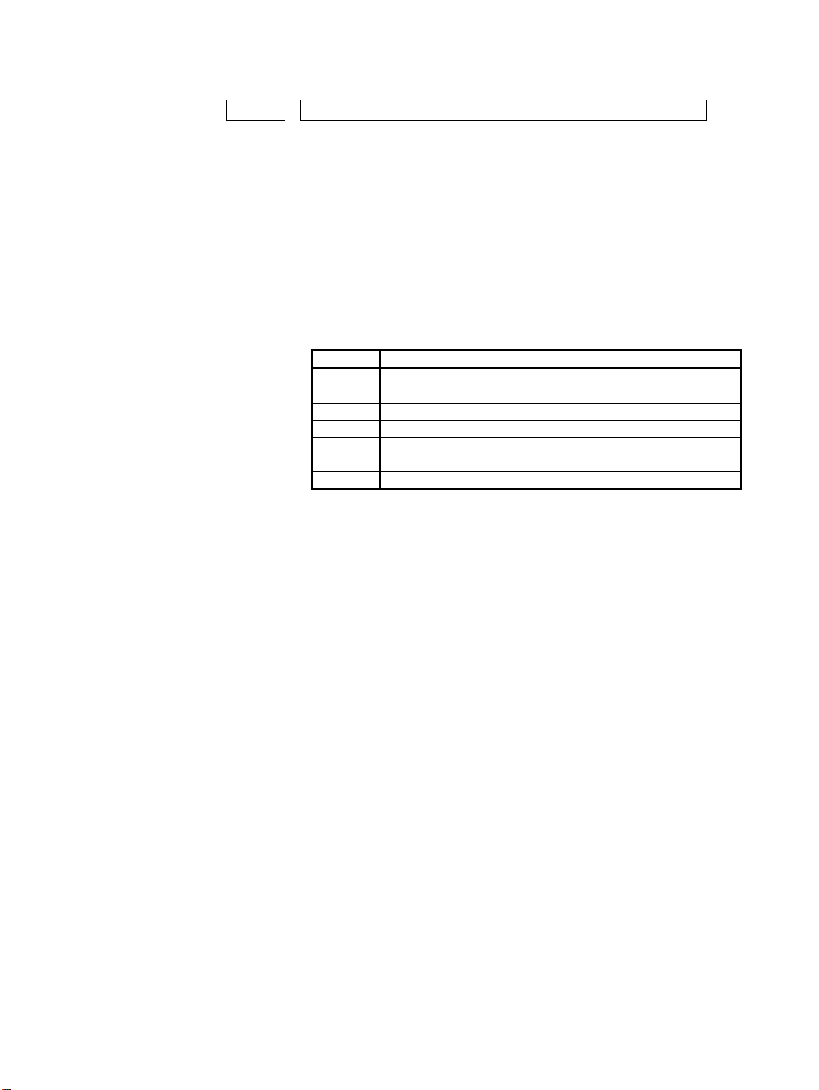
4.DESCRIPTION OF PARAMETERS B-63950EN/02
1022 Setting of each axis in the basic coordinate system
[Input type] Parameter input
[Data type] Byte axis
[Valid data range] 0 to 7
To determine a plane for circular interpolation, cutter compensation,
and so forth (G17: Xp-Yp plane, G18: Zp-Xp plane, G19: Yp-Zp
plane) and a three-dimensional tool compensation space (XpYpZp),
specify which of the basic three axes (X, Y, and Z) is used for each
control axis, or a parallel axis of which basic axis is used for each
control axis.
A basic axis (X, Y, or Z) can be specified only for one control axis.
Two or more control axes can be set as parallel axes for the same basic
axis.
Setting Meaning
0 Rotation axis (Neither the basic three axes nor a parallel axis )
1 X axis of the basic three axes
2 Y axis of the basic three axes
3 Z axis of the basic three axes
5 Axis parallel to the X axis
6 Axis parallel to the Y axis
7 Axis parallel to the Z axis
In general, the increment system and diameter/radius specification of
an axis set as a parallel axis are to be set in the same way as for the
basic three axes.
- 48 -
Page 61

B-63950EN/02 4.DESCRIPTION OF PARAMETERS
1023 Number of the servo axis for each axis
NOTE
When this parameter is set, the power must be
turned off before operation is continued.
[Input type] Parameter input
[Data type] Byte axis
[Valid data range] 0 to Number of controlled axes
Set the servo axis for each control axis.
Usually set to same number as the control axis number.
The control axis number is the order number that is used for setting
the axis-type parameters or axis-type machine signals
* With an axis for which Cs contour control/spindle positioning is
to be performed, set -(spindle number) as the servo axis number.
Example)
When exercising Cs contour control on the fourth controlled axis
by using the first spindle, set -1.
* For tandem controlled axes or electronic gear box (EGB)
controlled axes, two axes need to be specified as one pair. So,
make a setting as described below.
Tandem axis:
For a master axis, set an odd (1, 3, 5, 7, ...) servo axis number.
For a slave axis to be paired, set a value obtained by adding 1 to
the value set for the master axis.
EGB axis:
For a slave axis, set an odd (1, 3, 5, 7, ...) servo axis number.
For a dummy axis to be paired, set a value obtained by adding 1
to the value set for the slave axis.
1025 Program axis name 2 for each axis
1026 Program axis name 3 for each axis
[Input type] Parameter input
[Data type] Byte axis
[Valid data range] 48 to 57, 65 to 90
When axis name extension is enabled (when bit 0 (EEA) of parameter
No. 1000 is set to 1), the length of an axis name can be extended to a
maximum of three characters by setting axis name 2 and axis name 3.
NOTE
If program axis name 2 is not set, program axis
name 3 is invalid.
- 49 -
Page 62

4.DESCRIPTION OF PARAMETERS B-63950EN/02
1031 Reference axis
[Input type] Parameter input
[Data type] Byte path
[Valid data range] 0 to Number of controlled axes
The unit of some parameters common to all axes such as those for dry
run feedrate and single-digit F1 feedrate may vary according to the
increment system. An increment system can be selected by a
parameter on an axis-by-axis basis. So, the unit of those parameters
is to match the increment system of a reference axis. Set which axis
to use as a reference axis.
Among the basic three axes, the axis with the finest increment system
is generally selected as a reference axis.
- 50 -
Page 63

B-63950EN/02 4.DESCRIPTION OF PARAMETERS
4.9 PARAMETERS OF COORDINATES
#7 #6 #5 #4 #3 #2 #1 #0
1201
[Input type] Parameter input
[Data type] Bit path
# 0 ZPR Automatic setting of a coordinate system when the manual reference
# 2 ZCL Local coordinate system when the manual reference position return is
# 3 FPC When a floating reference position is set with a soft key, the relative
# 6 NWS The workpiece coordinate system shift amount setting screen is:
WZR NWS FPC ZCL ZPR
WZR FPC ZCL ZPR
position return is performed
0: Not set automatically
1: Set automatically
NOTE
ZPR is valid while a workpiece coordinate system
function is not provided. If a workpiece coordinate
system function is provided, making a manual
reference position return always causes the
workpiece coordinate system to be established on
the basis of the workpiece zero point offset
(parameters No. 1220 to No. 1226), irrespective of
this parameter setting.
performed
0: The local coordinate system is not canceled.
1: The local coordinate system is canceled.
NOTE
ZCL is valid when the workpiece coordinate system
option is specified. In order to use the local
coordinate system (G52), the workpiece coordinate
system option is required.
position indication is:
0: Not preset to 0 (The relative position indication remains
unchanged.)
1: Preset to 0.
0: Displayed
1: Not displayed
- 51 -
Page 64

4.DESCRIPTION OF PARAMETERS B-63950EN/02
NOTE
When the workpiece coordinate shift amount
setting screen is not displayed, a workpiece
coordinate system shift amount modification using
G10P0 cannot be made.
# 7 WZR If the CNC is reset by the reset key on the MDI panel, external reset
signal, reset and rewind signal, or emergency stop signal when bit 6
(CLR) of parameter No. 3402 is set to 0, the G code of group number
14 (workpiece coordinate system) is:
0: Placed in the reset state
1: Not placed in the reset state
NOTE
1 When the three-dimensional conversion mode is
set, and bit 2 (D3R) of parameter No. 5400 is set to
1, the G code is placed in the reset state,
regardless of the setting of this parameter.
2 When bit 6 (CLR) of parameter No. 3402 is set to
1, whether to place the G code in the reset state
depends on bit 6 (C14) of parameter No. 3407.
#7 #6 #5 #4 #3 #2 #1 #0
1202
[Input type] Parameter input
[Data type] Bit path
# 0 EWD The shift direction of the workpiece coordinate system is:
# 1 EWS The external workpiece zero point offset is made:
RLC G92 EWS EWD
RLC G92 EWD
0: The direction specified by the external workpiece zero point
offset value
1: In the opposite direction to that specified by the external
workpiece zero point offset value
0: Valid
1: Invalid
- 52 -
Page 65

B-63950EN/02 4.DESCRIPTION OF PARAMETERS
NOTE
When the external workpiece zero point offset is
made invalid, the following operation results:
1 As the external workpiece zero point offset on
the workpiece zero point offset setting screen, a
workpiece coordinate system shift amount is
displayed.
2 Data keyed through the MDI panel for the
workpiece coordinate system shift amount and
external workpiece zero point offset is loaded
into the memory for the workpiece coordinate
system shift amount.
3 A write to or read from the workpiece coordinate
system shift amount and external workpiece
zero point offset with a macro variable is
performed using the respective memory.
4 A write to or read from the workpiece coordinate
system shift amount and external workpiece
zero point offset with the window function is
performed using the respective memory.
# 2 G92 When the CNC has commands G52 to G59 specifying workpiece
coordinate systems (optional function), if the G command for setting a
coordinate system (G92 for M series, G50 for T series (or the G92
command in G command system B or C)) is specified,
0: G command is executed and no alarm is issued.
1: G command is not executed and an alarm (PS0010) is issued.
# 3 RLC Local coordinate system is
0: Not cancelled by reset
1: Cancelled by reset
NOTE
1 When bit 6 (CLR) of parameter No. 3402 is set to
0, and bit 7 (WZR) of parameter No. 1201 is set to
1, the local coordinate system is cancelled,
regardless of the setting of this parameter.
2 When bit 6 (CLR) of parameter No. 3402 is set to
1, and bit 6 (C14) of parameter No. 3407 is set to
0, the local coordinate system is cancelled,
regardless of the setting of this parameter.
3 When the three-dimensional coordinate conversion
mode is set, and bit 2 (D3R) of parameter No. 5400
is set to 1, the local coordinate system is not
cancelled, regardless of the setting of this
parameter.
- 53 -
Page 66

4.DESCRIPTION OF PARAMETERS B-63950EN/02
#7 #6 #5 #4 #3 #2 #1 #0
1203 EMS
[Input type] Parameter input
[Data type] Bit path
# 0 EMS The extended external machine zero point shift function is:
0: Disabled.
1: Enabled.
NOTE
1 To use the extended external machine zero
point shift function, the external machine zero
point shift function or the external data input
function is required.
2 When the extended external machine zero
point shift function is enabled, the conventional
external machine zero point shift function is
disabled.
#7 #6 #5 #4 #3 #2 #1 #0
1205 R2O R1O
[Input type] Parameter input
[Data type] Bit path
# 4 R1O The output of the signal for the reference position is:
0: Disabled.
1: Enabled.
# 5 R2O The output of the signal for the second reference position is:
0: Disabled.
1: Enabled.
1220 External workpiece zero point offset value in each axis
[Input type] Setting input
[Data type] Real axis
[Unit of data] mm, inch, degree (input unit)
[Minimum unit of data] Depend on the increment system of the applied axis
[Valid data range] 9 digit of minimum unit of data (refer to standard parameter setting
table (A) )
(When the increment system is IS-B, -999999.999 to +999999.999)
This is one of the parameters that give the position of the zero point of
workpiece coordinate system (G54 to G59). It gives an offset of the
workpiece zero point common to all workpiece coordinate systems. In
general, the offset varies depending on the workpiece coordinate
systems. The value can be set from the PMC using the external data
input function.
- 54 -
Page 67

B-63950EN/02 4.DESCRIPTION OF PARAMETERS
1221 Workpiece zero point offset value in workpiece coordinate system 1 (G54)
1222 Workpiece zero point offset value in workpiece coordinate system 2(G55)
1223 Workpiece zero point offset value in workpiece coordinate system 3(G56)
1224 Workpiece zero point offset value in workpiece coordinate system 4 (G57)
1225 Workpiece zero point offset value in workpiece coordinate system 5 (G58)
1226 Workpiece zero point offset value in workpiece coordinate system 6 (G59)
[Input type] Setting input
[Data type] Real axis
[Unit of data] mm, inch, degree (input unit)
[Minimum unit of data] Depend on the increment system of the applied axis
[Valid data range] 9 digit of minimum unit of data (refer to standard parameter setting
table (A) )
(When the increment system is IS-B, -999999.999 to +999999.999)
The workpiece zero point offset values in workpiece coordinate
systems 1 to 6 (G54 to G59) are set.
1240 Coordinate value of the reference position in the machine coordinate system
NOTE
When this parameter is set, the power must be
turned off before operation is continued.
[Input type] Parameter input
[Data type] Real axis
[Unit of data] mm, inch, degree (machine unit)
[Minimum unit of data] Depend on the increment system of the applied axis
[Valid data range] 9 digit of minimum unit of data (refer to standard parameter setting
table (A) )
(When the increment system is IS-B, -999999.999 to +999999.999)
Set the coordinate values of the reference position in the machine
coordinate system.
- 55 -
Page 68

4.DESCRIPTION OF PARAMETERS B-63950EN/02
1241
1242
1243
[Input type] Parameter input
[Data type] Real axis
[Unit of data] mm, inch, degree (machine unit)
[Minimum unit of data] Depend on the increment system of the applied axis
[Valid data range] 9 digit of minimum unit of data (refer to standard parameter setting
1244
[Input type] Parameter input
[Data type] Real axis
[Unit of data] mm, inch, degree (machine unit)
[Minimum unit of data] Depend on the increment system of the applied axis
[Valid data range] 9 digit of minimum unit of data (refer to standard parameter setting
1250
[Input type] Parameter input
[Data type] Real axis
[Unit of data] mm, inch, degree (input unit)
[Minimum unit of data] Depend on the increment system of the applied axis
[Valid data range] 9 digit of minimum unit of data (refer to standard parameter setting
Coordinate value of the second reference position in the machine coordinate
system
Coordinate value of the third reference position in the machine coordinate
system
Coordinate value of the fourth reference position in the machine coordinate
system
table (A) )
(When the increment system is IS-B, -999999.999 to +999999.999)
Set the coordinate values of the second to fourth reference positions in
the machine coordinate system.
Coordinate value of the floating reference position in the machine coordinate
system
table (A) )
(When the increment system is IS-B, -999999.999 to +999999.999)
Set the coordinate values of the floating reference position in the
machine coordinate system.
Coordinate system of the reference position used when automatic
coordinate system setting is performed
table (A) )
(When the increment system is IS-B, -999999.999 to +999999.999)
Set the coordinate system of the reference position on each axis to be
used for setting a coordinate system automatically.
- 56 -
Page 69

B-63950EN/02 4.DESCRIPTION OF PARAMETERS
1260 Amount of a shift per one rotation of a rotation axis
NOTE
When this parameter is set, the power must be
turned off before operation is continued.
[Input type] Parameter input
[Data type] Real axis
[Unit of data] Degree
[Minimum unit of data] Depend on the increment system of the applied axis
[Valid data range] 0 or positive 9 digit of minimum unit of data (refer to the standard
parameter setting table (B) )
(When the increment system is IS-B, 0.0 to +999999.999)
Set the amount of a shift per one rotation of a rotation axis.
For the rotation axis used for cylindrical interpolation, set the standard
value.
1280
Start address of signals used with the extended external machine zero point
shift function
[Input type] Parameter input
[Data type] Word path
[Valid data range] Even number from 0 to 32767
Set the start address of signals used with the extended external
machine zero point shift function. If a nonexistent address value is
specified, this function is disabled.
If 100 is set, for example, this function uses R100 and up. The last R
address to be used depends on the number of controlled axes. When
eight controlled axes are used, R100 to R115 are used.
NOTE
If a nonexistent R address or an address in the
system area is set, this function is disabled.
1290
[Input type] Parameter input
[Data type] Real path
[Unit of data] mm, inch (input unit)
[Minimum unit of data] Depend on the increment system of the reference axis
[Valid data range] 0 or positive 9 digit of minimum unit of data (refer to the standard
Distance between two opposite tool posts in mirror image
parameter setting table (B) )
(When the increment system is IS-B, 0.0 to +999999.999)
Set the distance between two opposite tool posts in mirror image.
- 57 -
Page 70

4.DESCRIPTION OF PARAMETERS B-63950EN/02
4.10 PARAMETERS OF STORED STROKE CHECK
#7 #6 #5 #4 #3 #2 #1 #0
1300 BFA RL3 LMS NAL OUT
[Input type] Setting input
[Data type] Bit path
# 0 OUT The area inside or outside of the stored stroke check 2 is set as an
inhibition area
0: Inside
1: Outside
# 1 NAL When the tool enters the inhibition area of stored stroke limit 1:
0: The overtravel alarm signal is not output.
1: The overtravel alarm signal is output, and the tool is decelerated
to a stop.
If manual operation is in progress at this time, the alarm is not
output.
NOTE
When this parameter is set to 1, the alarm is issued
if the tool enters stored stroke limit 1 during
automatic operation.
# 2 LMS The EXLM signal for switching stored stroke check
0: Disabled
1: Enabled
When bit 0 (DLM) of parameter No. 1301 is set to 1, the stored stroke
check 1 switch signal EXLM (G007#6) is made invalid.
# 5 RL3 Stored stroke check 3 release signal RLSOT3 is
0: Disabled
1: Enabled
# 7 BFA When the stored stroke check 1, 2, or 3 alarm is issued, an interference
alarm is issued with the inter-path interference check function (T
series), or a chuck/tail stock barrier (T series) alarm is issued:
0: The tool stops after entering the prohibited area.
1: The tool stops before the prohibited area.
- 58 -
Page 71

B-63950EN/02 4.DESCRIPTION OF PARAMETERS
#7 #6 #5 #4 #3 #2 #1 #0
1301 PLC OTS NPC DLM
[Input type] Setting input
[Data type] Bit path
# 0 DLM The stored stroke limit switching signals +EXLx and -EXLx for each
axial direction are:
0: Disabled.
1: Enabled.
When this parameter is set to 1, the stored stroke check 1 switch signal
EXLM (G007#6) is made invalid.
# 2 NPC As part of the stroke limit check performed before movement, the
movement specified in G31 (skip) and G37 (automatic tool length
measurement) blocks is:
0: Checked
1: Not checked
NOTE
This parameter is valid only when the option for
stroke check before movement is selected.
# 6 OTS When the overtravel alarm is issued:
0: The overtravel alarm signal is not output to the PMC.
1: The overtravel alarm signal is output to the PMC.
# 7 PLC Stroke check before movement is:
0: Not performed
1: Performed
NOTE
This parameter is valid only when the option for
stroke check before movement is selected.
#7 #6 #5 #4 #3 #2 #1 #0
1310 OT3x OT2x
[Input type] Setting input
[Data type] Bit axis
# 0 OT2x Stored stroke check 2 for each axis is :
0: Disabled
1: Enabled
# 1 OT3x Stored stroke check 3 for each axis is :
0: Disabled
1: Enabled
- 59 -
Page 72

4.DESCRIPTION OF PARAMETERS B-63950EN/02
1320
Coordinate value I of stored stroke check 1 in the positive direction on each axis
1321
Coordinate value I of stored stroke check 1 in the negative direction on each axis
[Input type] Parameter input
[Data type] Real axis
[Unit of data] mm, inch, degree (machine unit)
[Minimum unit of data] Depend on the increment system of the applied axis
[Valid data range] 9 digit of minimum unit of data (refer to standard parameter setting
table (A) )
(When the increment system is IS-B, -999999.999 to +999999.999)
Set the coordinate value of stored stroke check 1 on each axis in the +
or - direction in the machine coordinate system.
NOTE
1 Specify diameter values for any axes for which
diameter programming is specified.
2 The area outside the area set by parameter No.
1320 and No. 1321 is a prohibited area.
1322
Coordinate value I of stored stroke check 2 in the positive direction on each axis
1323
Coordinate value I of stored stroke check 2 in the negative direction on each axis
[Input type] Setting input
[Data type] Real axis
[Unit of data] mm, inch, degree (machine unit)
[Minimum unit of data] Depend on the increment system of the applied axis
[Valid data range] 9 digit of minimum unit of data (refer to standard parameter setting
table (A) )
(When the increment system is IS-B, -999999.999 to +999999.999)
Set the coordinate value of stored stroke check 2 on each axis in the +
or - direction in the machine coordinate system.
NOTE
1 Specify diameter values for any axes for which
diameter programming is specified.
2 Whether the inside area or outside area is a
prohibited area is set using bit 0 (OUT) of
parameter No. 1300.
- 60 -
Page 73

B-63950EN/02 4.DESCRIPTION OF PARAMETERS
1324
Coordinate value I of stored stroke check 3 in the positive direction on each axis
1325
Coordinate value I of stored stroke check 3 in the negative direction on each axis
[Input type] Setting input
[Data type] Real axis
[Unit of data] mm, inch, degree (machine unit)
[Minimum unit of data] Depend on the increment system of the applied axis
[Valid data range] 9 digit of minimum unit of data (refer to standard parameter setting
table (A) )
(When the increment system is IS-B, -999999.999 to +999999.999)
Set the coordinate value of stored stroke check 3 on each axis in the +
or - direction in the machine coordinate system.
NOTE
1 Specify diameter values for any axes for which
diameter programming is specified.
2 The area inside the area set by parameter No.
1324 and No. 1325 is a prohibited area.
1326
Coordinate value II of stored stroke check 1 in the negative direction on each axis
1327
Coordinate value II of stored stroke check 1 in the negative direction on each axis
[Input type] Parameter input
[Data type] Real axis
[Unit of data] mm, inch, degree (machine unit)
[Minimum unit of data] Depend on the increment system of the applied axis
[Valid data range] 9 digit of minimum unit of data (refer to standard parameter setting
table (A) )
(When the increment system is IS-B, -999999.999 to +999999.999)
Set the coordinate value of stored stroke check 1 on each axis in the +
or - direction in the machine coordinate system.
When the stored stroke check switch signal EXLM is set to 1, or the
stored stroke check switch signal for each axis direction +EXLx is set
to 1, parameter No. 1326 and No. 1327 are used for stroke check
instead of parameter No.1320 and No. 1321.
NOTE
1 Specify diameter values for any axes for which
diameter programming is specified.
2 The area outside the area set by parameter No.
1326 and No. 1327 is a prohibited area.
3 The EXLM signal is valid only when bit 2 (LMS) of
parameter No. 1300 is set to 1.
4 The +EXLx signal is valid only when bit 0 (DLM) of
parameter No. 1301 is set to 1.
- 61 -
Page 74

4.DESCRIPTION OF PARAMETERS B-63950EN/02
4.11 PARAMETERS OF THE CHUCK AND TAIL STOCK
BARRIER
1330
[Input type] Parameter input
[Data type] Byte path
[Valid data range] 0 to 1
1331
[Input type] Parameter input
[Data type] Real path
[Unit of data] mm, inch (input unit)
[Minimum unit of data] Depend on the increment system of the applied axis
[Valid data range] 0 or positive 9 digit of minimum unit of data (refer to the standard
1332
[Input type] Parameter input
[Data type] Real path
[Unit of data] mm, inch (input unit)
[Minimum unit of data] Depend on the increment system of the applied axis
[Valid data range] 0 or positive 9 digit of minimum unit of data (refer to the standard
Profile of a chuck
Select a chuck figure.
0 : Chuck which holds a workpiece on the inner surface
1 : Chuck which holds a workpiece on the outer surface
Dimensions of the claw of a chuck (L)
parameter setting table (B) )
(When the increment system is IS-B, 0.0 to +999999.999)
Set the length (L) of the claw of the chuck.
NOTE
Whether to specify this parameter by using a
diameter value or radius value depends on whether
the corresponding axis is based on diameter
specification or radius specification.
Dimensions of the claw of a chuck (W)
parameter setting table (B) )
(When the increment system is IS-B, 0.0 to +999999.999)
Set the width (W) of the claw of the chuck.
NOTE
Specify this parameter by using a radius value at
all times.
- 62 -
Page 75

B-63950EN/02 4.DESCRIPTION OF PARAMETERS
1333
Dimensions of the part of a claw at which a workpiece is held (L1)
[Input type] Parameter input
[Data type] Real path
[Unit of data] mm, inch (input unit)
[Minimum unit of data] Depend on the increment system of the applied axis
[Valid data range] 0 or positive 9 digit of minimum unit of data (refer to the standard
parameter setting table (B) )
(When the increment system is IS-B, 0.0 to +999999.999)
Set the length (L1) of the claw of the chuck.
NOTE
Whether to specify this parameter by using a
diameter value or radius value depends on whether
the corresponding axis is based on diameter
specification or radius specification.
1334
Dimensions of the part of a claw at which a workpiece is held (W1)
[Input type] Parameter input
[Data type] Real path
[Unit of data] mm, inch (input unit)
[Minimum unit of data] Depend on the increment system of the applied axis
[Valid data range] 0 or positive 9 digit of minimum unit of data (refer to the standard
parameter setting table (B) )
(When the increment system is IS-B, 0.0 to +999999.999)
Set the width (W1) of the claw of the chuck.
NOTE
Specify this parameter by using a radius value at
all times.
1335
[Input type] Parameter input
[Data type] Real path
[Unit of data] mm, inch (input unit)
[Minimum unit of data] Depend on the increment system of the applied axis
[Valid data range] 9 digit of minimum unit of data (refer to standard parameter setting
X coordinate of a chuck (CX)
table (A) )
(When the increment system is IS-B, -999999.999 to +999999.999)
Set the chuck position (X coordinate) in the workpiece coordinate
system.
- 63 -
Page 76

4.DESCRIPTION OF PARAMETERS B-63950EN/02
NOTE
Whether to specify this parameter by using a
diameter value or radius value depends on whether
the corresponding axis is based on diameter
specification or radius specification.
1336
Z coordinate of a chuck (CZ)
[Input type] Parameter input
[Data type] Real path
[Unit of data] mm, inch (input unit)
[Minimum unit of data] Depend on the increment system of the applied axis
[Valid data range] 9 digit of minimum unit of data (refer to standard parameter setting
table (A) )
(When the increment system is IS-B, -999999.999 to +999999.999)
Set the chuck position (Z coordinate) in the workpiece coordinate
system.
NOTE
Whether to specify this parameter by using a
diameter value or radius value depends on whether
the corresponding axis is based on diameter
specification or radius specification.
1341
Length of a tail stock (L)
[Input type] Parameter input
[Data type] Real path
[Unit of data] mm, inch (input unit)
[Minimum unit of data] Depend on the increment system of the applied axis
[Valid data range] 0 or positive 9 digit of minimum unit of data (refer to the standard
parameter setting table (B) )
(When the increment system is IS-B, 0.0 to +999999.999)
Set the length (L) of the tail stock.
NOTE
Whether to specify this parameter by using a
diameter value or radius value depends on whether
the corresponding axis is based on diameter
specification or radius specification.
- 64 -
Page 77

B-63950EN/02 4.DESCRIPTION OF PARAMETERS
1342
Diameter of a tail stock (D)
[Input type] Parameter input
[Data type] Real path
[Unit of data] mm, inch (input unit)
[Minimum unit of data] Depend on the increment system of the applied axis
[Valid data range] 0 or positive 9 digit of minimum unit of data (refer to the standard
parameter setting table (B) )
(When the increment system is IS-B, 0.0 to +999999.999)
Set the diameter (D) of the tail stock.
NOTE
Specify this parameter by using a diameter value at
all times.
1343
Length of a tail stock (L1)
[Input type] Parameter input
[Data type] Real path
[Unit of data] mm, inch (input unit)
[Minimum unit of data] Depend on the increment system of the applied axis
[Valid data range] 0 or positive 9 digit of minimum unit of data (refer to the standard
parameter setting table (B) )
(When the increment system is IS-B, 0.0 to +999999.999)
Set the length (L1) of the tail stock.
NOTE
Whether to specify this parameter by using a
diameter value or radius value depends on whether
the corresponding axis is based on diameter
specification or radius specification.
1344
Diameter of a tail stock (D1)
[Input type] Parameter input
[Data type] Real path
[Unit of data] mm, inch (input unit)
[Minimum unit of data] Depend on the increment system of the applied axis
[Valid data range] 0 or positive 9 digit of minimum unit of data (refer to the standard
parameter setting table (B) )
(When the increment system is IS-B, 0.0 to +999999.999)
Set the diameter (D1) of the tail stock.
NOTE
Specify this parameter by using a diameter value at
all times.
- 65 -
Page 78

4.DESCRIPTION OF PARAMETERS B-63950EN/02
1345
Length of a tail stock (L2)
[Input type] Parameter input
[Data type] Real path
[Unit of data] mm, inch (input unit)
[Minimum unit of data] Depend on the increment system of the applied axis
[Valid data range] 0 or positive 9 digit of minimum unit of data (refer to the standard
parameter setting table (B) )
(When the increment system is IS-B, 0.0 to +999999.999)
Set the length (L2) of the tail stock.
NOTE
Whether to specify this parameter by using a
diameter value or radius value depends on whether
the corresponding axis is based on diameter
specification or radius specification.
1346
Diameter of a tail stock (D2)
[Input type] Parameter input
[Data type] Real path
[Unit of data] mm, inch (input unit)
[Minimum unit of data] Depend on the increment system of the applied axis
[Valid data range] 0 or positive 9 digit of minimum unit of data (refer to the standard
parameter setting table (B) )
(When the increment system is IS-B, 0.0 to +999999.999)
Set the diameter (D2) of the tail stock.
NOTE
Specify this parameter by using a diameter value at
all times.
1347
Diameter of the hole of a tail stock (D3)
[Input type] Parameter input
[Data type] Real path
[Unit of data] mm, inch (input unit)
[Minimum unit of data] Depend on the increment system of the applied axis
[Valid data range] 0 or positive 9 digit of minimum unit of data (refer to the standard
parameter setting table (B) )
(When the increment system is IS-B, 0.0 to +999999.999)
Set the diameter (D3) of the tail stock.
NOTE
Specify this parameter by using a diameter value at
all times.
- 66 -
Page 79

B-63950EN/02 4.DESCRIPTION OF PARAMETERS
1348
Z coordinate of a tail stock (TZ)
[Input type] Parameter input
[Data type] Real path
[Unit of data] mm, inch (input unit)
[Minimum unit of data] Depend on the increment system of the applied axis
[Valid data range] 9 digit of minimum unit of data (refer to standard parameter setting
table (A) )
(When the increment system is IS-B, -999999.999 to +999999.999)
Set the tail stock position (Z coordinate) in the workpiece coordinate
system.
NOTE
Whether to specify this parameter by using a
diameter value or radius value depends on whether
the corresponding axis is based on diameter
specification or radius specification.
- 67 -
Page 80

4.DESCRIPTION OF PARAMETERS B-63950EN/02
4.12 PARAMETERS OF FEEDRATE
#7 #6 #5 #4 #3 #2 #1 #0
1401 RDR TDR RF0 JZR LRP RPD
[Input type] Parameter input
[Data type] Bit path
# 0 RPD Manual rapid traverse during the period from power-on time to the
completion of the reference position return.
0: Disabled (Jog feed is performed.)
1: Enabled
# 1 LRP Positioning (G00)
0: Positioning is performed with non-linear type positioning so that
the tool moves along each axis independently at rapid traverse.
1: Positioning is performed with linear interpolation so that the tool
moves in a straight line.
When using three-dimensional coordinate conversion, set this
parameter to 1.
# 2 JZR The manual reference position return at JOG feedrate
0: Not performed
1: Performed
# 4 RF0 When cutting feedrate override is 0% during rapid traverse,
0: The machine tool does not stop moving.
1: The machine tool stops moving.
# 5 TDR Dry run during threading or tapping (tapping cycle G74 or G84, rigid
tapping)
0: Enabled
1: Disabled
# 6 RDR Dry run for rapid traverse command
0: Disabled
1: Enabled
#7 #6 #5 #4 #3 #2 #1 #0
1402 JRV OV2 JOV NPC
[Input type] Parameter input
[Data type] Bit path
# 0 NPC Feed per revolution without the position coder (function for
converting feed per revolution F to feed per minute F in the feed per
revolution mode (G95)) is:
0: Not used
1: Used
- 68 -
Page 81

B-63950EN/02 4.DESCRIPTION OF PARAMETERS
# 1 JOV Jog override is:
0: Enabled
1: Disabled (tied to 100%)
# 3 OV2 Signals used for 2nd feedrate override are
0: *AFV0 to AFV7 <G013> (specified every 1%)
1: *APF00 to *APF15 <G094, G095> (specified every 0.01%)
# 4 JRV Jog feed or incremental feed is
0: Performed at feed per minute.
1: Performed at feed per rotation.
NOTE
1 Specify a feedrate in parameter No.1423.
2 For the machining center system, the option for
threading/synchronous feed is required.
#7 #6 #5 #4 #3 #2 #1 #0
1403
[Input type] Parameter input
[Data type] Bit path
# 4 ROC In the threading cycles G92 and G76, rapid traverse override for
# 5 HTG The feedrate for helical interpolation/helical involute
# 7 RTV Rapid traverse override while the tool is retracting in threading
RTV HTG ROC
HTG
retraction after threading is finished is:
0: Effective
1: Not effective (Override of 100%)
interpolation/three-dimensional circular interpolation is:
0: Specified using the feedrate along the tangent to an arc/involute
curve/three-dimensional arc
1: Specified using the feedrate along axes including a linear axis
(specified axes other than the circular interpolation axis in the
case of three-dimensional circular interpolation)
0: Rapid traverse override is effective.
1: Rapid traverse override is not effective.
- 69 -
Page 82

4.DESCRIPTION OF PARAMETERS B-63950EN/02
#7 #6 #5 #4 #3 #2 #1 #0
1404
FM3 DLF
DLF
[Input type] Parameter input
[Data type] Bit path
# 1 DLF After a reference position is set, manual reference position return
performed at:
0: Rapid traverse rate (parameter No.1420)
1: Manual rapid traverse rate (parameter No.1424)
NOTE
This parameter selects a feedrate for reference
position return performed without dogs. This
parameter also selects a feedrate when manual
reference position return is performed according to
bit 7 (SJZ) of parameter No.0002 using rapid
traverse without deceleration dogs after a
reference position is set.
# 2 FM3 The increment system of an F command without a decimal point in
feed per minute is:
0: 1 mm/min (0.01 inch/min for inch input)
1: 0.001 mm/min (0.00001 inch/min for inch input)
#7 #6 #5 #4 #3 #2 #1 #0
1405
EDR PCL
EDR PCL FR3
[Input type] Parameter input
[Data type] Bit path
# 1 FR3 The increment system of an F command without a decimal point in
feed per revolution is:
0: 0.01 mm/rev (0.0001 inch/rev for inch input)
1: 0.001 mm/rev (0.00001 inch/rev for inch input)
# 2 PCL The function for constant surface speed control without the position
coder is:
0: Not used.
1: Used.
NOTE
The option for constant surface speed control
without the position coder is required.
- 70 -
Page 83

B-63950EN/02 4.DESCRIPTION OF PARAMETERS
# 5 EDR As the external deceleration rate for positioning of linear interpolation
type:
0: The external deceleration rate for cutting feed is used.
1: The external deceleration rate for the first axis in rapid traverse is
used.
Let us use external deceleration 1 as an example.
When this parameter bit is set to 0, the value of parameter No. 1426 is
used as the external deceleration rate for external deceleration 1.
When this parameter bit is set to 1, the value of axis 1 of parameter No.
1427 is used as the external deceleration rate for external deceleration
1.
#7 #6 #5 #4 #3 #2 #1 #0
1406 EX3 EX2
[Input type] Parameter input
[Data type] Bit path
# 0 EX2 External deceleration function setting 2 is:
0: Invalid
1: Valid
# 1 EX3 External deceleration function setting 3 is:
0: Invalid
1: Valid
#7 #6 #5 #4 #3 #2 #1 #0
1408 RFDx
[Input type] Parameter input
[Data type] Bit axis
# 0 RFDx Feedrate control on a rotation axis is exercised using:
0: Conventional method
1: Method that specifies a feedrate on the virtual circle of the
rotation axis
1410 Dry run rate
[Input type] Parameter input
[Data type] Real path
[Unit of data] mm/min, inch/min, degree/min (machine unit)
[Minimum unit of data] Depend on the increment system of the reference axis
[Valid data range] Refer to the standard parameter setting table (C)
(When the increment system is IS-B, 0.0 to +240000.0)
Set the dry run rate at the 100% position on the jog feedrate
specification dial. The unit of data depends on the increment system of
the reference axis.
- 71 -
Page 84

4.DESCRIPTION OF PARAMETERS B-63950EN/02
1411
Cutting feedrate
NOTE
When this parameter is set, the power must be
turned off before operation is continued.
[Input type] Setting input
[Data type] Real path
[Unit of data] mm/min, inch/min, degree/min (input unit)
[Minimum unit of data] Depend on the increment system of the reference axis
[Valid data range] Refer to the standard parameter setting table (C)
(When the increment system is IS-B, 0.0 to +240000.0)
When the machine requires little change in cutting feedrate during
cutting, a cutting feedrate can be specified in the parameter. This
eliminates the need to specify a cutting feedrate (F command) in the
NC program.
1414
[Input type] Parameter input
[Data type] Real path
[Unit of data] mm/min, inch/min, degree/min (machine unit)
[Minimum unit of data] Depend on the increment system of the reference axis
[Valid data range] Refer to the standard parameter setting table (C)
1420 Rapid traverse rate for each axis
[Input type] Parameter input
[Data type] Real axis
[Unit of data] mm/min, inch/min, degree/min (machine unit)
[Minimum unit of data] Depend on the increment system of the applied axis
[Valid data range] Refer to the standard parameter setting table (C)
1421 F0 rate of rapid traverse override for each axis
[Input type] Parameter input
[Data type] Real axis
[Unit of data] mm/min, inch/min, degree/min (machine unit)
[Minimum unit of data] Depend on the increment system of the applied axis
[Valid data range] Refer to the standard parameter setting table (C)
Feedrate for retrace
(When the increment system is IS-B, 0.0 to +240000.0)
Set a cutting feedrate for retrace operation. When 0 is set, a retrace
operation is performed at a programmed feedrate.
(When the increment system is IS-B, 0.0 to +240000.0)
Set the rapid traverse rate when the rapid traverse override is 100% for
each axis.
(When the increment system is IS-B, 0.0 to +240000.0)
Set the F0 rate of the rapid traverse override for each axis.
- 72 -
Page 85

B-63950EN/02 4.DESCRIPTION OF PARAMETERS
1423 Feedrate in manual continuous feed (jog feed) for each axis
[Input type] Parameter input
[Data type] Real axis
[Unit of data] mm/min, inch/min, degree/min (machine unit)
[Minimum unit of data] Depend on the increment system of the applied axis
[Valid data range] Refer to the standard parameter setting table (C)
(When the increment system is IS-B, 0.0 to +240000.0)
(1) When JRV, bit 4 of parameter No.1402, is set to 0 (feed per
minute), specify a jog feedrate (feed per minute) under an
override of 100%.
(2) When JRV, bit 4 of parameter No.1402, is set to 1 (feed per
revolution), specify a jog feedrate (feed per revolution) under an
override of 100%.
NOTE
This parameter is clamped to the axis-by-axis
manual rapid traverse rate (parameter No. 1424).
1424 Manual rapid traverse rate for each axis
[Input type] Parameter input
[Data type] Real axis
[Unit of data] mm/min, inch/min, degree/min (machine unit)
[Minimum unit of data] Depend on the increment system of the applied axis
[Valid data range] Refer to the standard parameter setting table (C)
(When the increment system is IS-B, 0.0 to +240000.0)
Set the rate of manual rapid traverse when the rapid traverse override
is 100% for each axis.
NOTE
1 If 0 is set, the rate set in parameter 1420 (rapid
traverse rate for each axis) is assumed.
2 When manual rapid traverse is selected (bit 0 (RPD)
of parameter No. 1401 is set to 1), manual feed is
performed at the feedrate set in this parameter,
regardless of the setting of bit 4 (JRV) of parameter
No. 1402.
1425 FL rate of the reference position return for each axis
[Input type] Parameter input
[Data type] Real axis
[Unit of data] mm/min, inch/min, degree/min (machine unit)
[Minimum unit of data] Depend on the increment system of the applied axis
[Valid data range] Refer to the standard parameter setting table (C)
(When the increment system is IS-B, 0.0 to +240000.0)
Set feedrate (FL rate) after deceleration when the reference position
return is performed for each axis.
- 73 -
Page 86

4.DESCRIPTION OF PARAMETERS B-63950EN/02
1426 External deceleration rate of cutting feed
[Input type] Parameter input
[Data type] Real path
[Unit of data] mm/min, inch/min, degree/min (machine unit)
[Minimum unit of data] Depend on the increment system of the reference axis
[Valid data range] Refer to the standard parameter setting table (C)
(When the increment system is IS-B, 0.0 to +240000.0)
Set an external deceleration rate for cutting feed or positioning of
linear interpolation type (G00).
1427 External deceleration rate of rapid traverse for each axis
[Input type] Parameter input
[Data type] Real axis
[Unit of data] mm/min, inch/min, degree/min (machine unit)
[Minimum unit of data] Depend on the increment system of the applied axis
[Valid data range] Refer to the standard parameter setting table (C)
(When the increment system is IS-B, 0.0 to +240000.0)
Set the external deceleration rate of rapid traverse for each axis.
1428 Reference position return feedrate for each axis
[Input type] Parameter input
[Data type] Real axis
[Unit of data] mm/min, inch/min, degree/min (machine unit)
[Minimum unit of data] Depend on the increment system of the applied axis
[Valid data range] Refer to the standard parameter setting table (C)
(When the increment system is IS-B, 0.0 to +240000.0)
This parameter sets a rapid traverse rate for reference position return
operation using deceleration dogs, or for reference position return
operation before a reference position is set.
This parameter is also used to set a feedrate for the rapid traverse
command (G00) in automatic operation before a reference position is
set.
- 74 -
Page 87

B-63950EN/02 4.DESCRIPTION OF PARAMETERS
NOTE
1 To this feedrate setting (100%), a rapid traverse
override (F0, 25, 50, or 100%) is applicable.
2 For automatic return after completion of reference
position return and machine coordinate system
establishment, the normal rapid traverse rate is used.
3 As a manual rapid traverse rate before machine
coordinate system establishment by reference
position return, the jog feedrate or manual rapid
traverse rate can be selected with bit 0 (RPD) of
parameter No. 1401.
Automatic reference
position return (G28)
Automatic rapid
traverse (G00)
Manual reference
position return *1
Manual rapid
traverse
Before coordinate
system
establishment
No.1428 No.1420
No.1428 No.1420
No.1428 No.1428 *3
No.1423 *2 No.1424
After coordinate
system
establishment
4 When parameter No. 1428 is set to 0, the following
parameter-set feedrates are applied.
Automatic reference
position return (G28)
Automatic rapid
traverse (G00)
Manual reference
position return *1
Manual rapid
traverse
Before coordinate
system
establishment
No.1420 No.1420
No.1420 No.1420
No.1424 No.1424 *3
No.1423 *2 No.1424
After coordinate
system
establishment
1420: rapid traverse rate
1423: Jog feedrate
1424: Manual rapid traverse rate
*1 : By using bit 2 (JZR) of parameter No. 1401, the
jog feedrate can be used for manual reference
position return at all times.
*2 : When bit 0 (RPD) of parameter No. 1401 is set to
1, the setting of parameter No. 1424 is used.
*3 : When rapid traverse is used for reference position
return without dogs or manual reference position
return after reference position establishment,
regardless of the deceleration dog, the feedrate
for manual reference position return based on
these functions is used (the setting of bit 1 (DLF)
of parameter No. 1404 is followed).
- 75 -
Page 88

4.DESCRIPTION OF PARAMETERS B-63950EN/02
1430 Maximum cutting feedrate for each axis
[Input type] Parameter input
[Data type] Real axis
[Unit of data] mm/min, inch/min, degree/min (machine unit)
[Minimum unit of data] Depend on the increment system of the applied axis
[Valid data range] Refer to the standard parameter setting table (C)
(When the increment system is IS-B, 0.0 to +240000.0)
Specify the maximum cutting feedrate for each axis.
1432
[Input type] Parameter input
[Data type] Real axis
[Unit of data] mm/min, inch/min, degree/min (machine unit)
[Minimum unit of data] Depend on the increment system of the applied axis
[Valid data range] Refer to the standard parameter setting table (C)
1434 Maximum manual handle feedrate for each axis
[Input type] Parameter input
[Data type] Real axis
[Unit of data] mm/min, inch/min, degree/min (machine unit)
[Minimum unit of data] Depend on the increment system of the applied axis
[Valid data range] Refer to the standard parameter setting table (C)
1440 External deceleration rate setting 2 in cutting feed
[Input type] Parameter input
[Data type] Real path
[Unit of data] mm/min, inch/min, degree/min (machine unit)
[Minimum unit of data] Depend on the increment system of the reference axis
[Valid data range] Refer to the standard parameter setting table (C)
Maximum cutting feedrate for all axes in the acceleration/deceleration before
interpolation
(When the increment system is IS-B, 0.0 to +240000.0)
Set a maximum cutting feedrate for each axis in the
acceleration/deceleration before interpolation mode such as AI
contour control. When the acceleration/deceleration before
interpolation mode is not set, the maximum cutting feedrate set in
parameter No. 1430 is used.
(When the increment system is IS-B, 0.0 to +240000.0)
Set a maximum manual handle feedrate for each axis.
(When the increment system is IS-B, 0.0 to +240000.0)
Set external deceleration rate 2 for cutting feed or positioning of linear
interpolation type (G00).
- 76 -
Page 89

B-63950EN/02 4.DESCRIPTION OF PARAMETERS
1441 External deceleration rate setting 2 for each axis in rapid traverse
[Input type] Parameter input
[Data type] Real axis
[Unit of data] mm/min, inch/min, degree/min (machine unit)
[Minimum unit of data] Depend on the increment system of the applied axis
[Valid data range] Refer to the standard parameter setting table (C)
(When the increment system is IS-B, 0.0 to +240000.0)
Set external deceleration rate 2 for each axis in rapid traverse.
1442 Maximum manual handle feedrate setting 2 for each axis
[Input type] Parameter input
[Data type] Real axis
[Unit of data] mm/min, inch/min, degree/min (machine unit)
[Minimum unit of data] Depend on the increment system of the applied axis
[Valid data range] Refer to the standard parameter setting table (C)
(When the increment system is IS-B, 0.0 to +240000.0)
Set a maximum manual handle feedrate 2 for each axis.
1443 External deceleration rate setting 3 in cutting feed
[Input type] Parameter input
[Data type] Real path
[Unit of data] mm/min, inch/min, degree/min (machine unit)
[Minimum unit of data] Depend on the increment system of the reference axis
[Valid data range] Refer to the standard parameter setting table (C)
(When the increment system is IS-B, 0.0 to +240000.0)
Set external deceleration rate 3 for cutting feed or positioning of linear
interpolation type (G00).
1444 External deceleration rate setting 3 for each axis in rapid traverse
[Input type] Parameter input
[Data type] Real axis
[Unit of data] mm/min, inch/min, degree/min (machine unit)
[Minimum unit of data] Depend on the increment system of the applied axis
[Valid data range] Refer to the standard parameter setting table (C)
(When the increment system is IS-B, 0.0 to +240000.0)
Set external deceleration rate 3 for each axis in rapid traverse.
1445 Maximum manual handle feedrate setting 3 for each axis
[Input type] Parameter input
[Data type] Real axis
[Unit of data] mm/min, inch/min (machine unit)
[Minimum unit of data] Depend on the increment system of the applied axis
[Valid data range] Refer to the standard parameter setting table (C)
(When the increment system is IS-B, 0.0 to +240000.0)
Set a maximum manual handle feedrate 3 for each axis.
- 77 -
Page 90

4.DESCRIPTION OF PARAMETERS B-63950EN/02
1466 Feedrate for retraction in threading cycle G92 or G76
[Input type] Parameter input
[Data type] Real path
[Unit of data] mm/min, inch/min (machine unit)
[Minimum unit of data] Depend on the increment system of the reference axis
[Valid data range] Refer to the standard parameter setting table (C)
(When the increment system is IS-B, 0.0 to +240000.0)
When threading cycle G92 or G76 is specified, retraction is performed
after threading. Set a feedrate for this retraction.
NOTE
When this parameter is set to 0 or bit 1 (CFR) of
parameter No. 1611 is set to 1, the rapid traverse
rate set in parameter No. 1420 is used.
- 78 -
Page 91

B-63950EN/02 4.DESCRIPTION OF PARAMETERS
4.13 PARAMETERS OF ACCELERATION/DECELERATION
CONTROL
#7 #6 #5 #4 #3 #2 #1 #0
1601 NCI RTO
[Input type] Parameter input
[Data type] Bit path
# 4 RTO Block overlap in rapid traverse
0: Blocks are not overlapped in rapid traverse.
1: Blocks are overlapped in rapid traverse.
# 5 NCI An in-position check:
0: Confirms that the specified feedrate becomes 0 (the
acceleration/deceleration delay becomes 0) at deceleration time
and that the machine position has reached a specified position
(the servo positional deviation is within the in-position width set
by parameter No. 1827).
1: Confirms only that the specified feedrate becomes 0 (the
acceleration/deceleration delay becomes 0) at deceleration time.
#7 #6 #5 #4 #3 #2 #1 #0
1602 LS2 BS2
[Input type] Parameter input
[Data type] Bit path
# 3 BS2 In the acceleration/deceleration before interpolation mode:
0: Exponential acceleration/deceleration or linear acceleration/
deceleration is used.
(The setting of bit 6 (LS2) of parameter No. 1602 is followed.)
1: Bell-shaped acceleration/deceleration is used.
# 6 LS2 In the acceleration/deceleration before interpolation mode:
0: Exponential acceleration/deceleration is used.
1: Linear acceleration/deceleration is used.
#7 #6 #5 #4 #3 #2 #1 #0
1603 PRT
[Input type] Parameter input
[Data type] Bit path
# 4 PRT For positioning of linear interpolation type:
0: Acceleration/deceleration of acceleration fixed type is used.
1: Acceleration/deceleration of time fixed type is used.
- 79 -
Page 92

4.DESCRIPTION OF PARAMETERS B-63950EN/02
#7 #6 #5 #4 #3 #2 #1 #0
1604 SHP
[Input type] Parameter input
[Data type] Bit path
# 0 SHP When automatic operation is started, the state equivalent to the
specification of G5.1Q1 for AI contour control is:
0: Not set
1: Set
Upon reset, the state where G5.1Q1 is specified is set.
#7 #6 #5 #4 #3 #2 #1 #0
1606 MNJx
[Input type] Parameter input
[Data type] Bit axis
# 0 MNJx In manual handle interrupt or automatic manual simultaneous
operation (interrupt type):
0: Only cutting feed acceleration/deceleration is enabled, and jog
feed acceleration/deceleration is disabled.
1: Both cutting feed acceleration/deceleration and jog feed
acceleration/deceleration are applied.
#7 #6 #5 #4 #3 #2 #1 #0
1610 JGLx CTBx CTLx
[Input type] Parameter input
[Data type] Bit axis
# 0 CTLx Acceleration/deceleration in cutting feed or dry run
0: Exponential acceleration/deceleration is applied.
1: Linear acceleration/deceleration after interpolation is applied.
# 1 CTBx Acceleration/deceleration in cutting feed or dry run
0: Exponential acceleration/deceleration or linear acceleration/
deceleration is applied.
(depending on the setting in CTLx, bit 0 of parameter No.1610)
1: Bell-shaped acceleration/deceleration is applied.
# 4 JGLx Acceleration/deceleration in jog feed
0: Exponential acceleration/deceleration is applied.
1: (depending on which is used for cutting feed. (depending on the
setting in CTBx or CTLx, bit 1 or 0 of parameter No.1610)
- 80 -
Page 93

B-63950EN/02 4.DESCRIPTION OF PARAMETERS
#7 #6 #5 #4 #3 #2 #1 #0
1611
CFR
[Input type] Parameter input
[Data type] Bit path
# 0 CFR For retraction after threading in the threading cycles G92 and G76:
0: The type of acceleration/deceleration after interpolation for
threading is used together with the threading time constant
(parameter No. 1626) and FL feedrate (parameter No. 1627).
1: The type of acceleration/deceleration after interpolation for rapid
traverse is used together with the rapid traverse time constant and
FL feedrate.
NOTE
When this parameter is set to 1, an in-position
check is made before retraction. For retraction, the
rapid traverse rate (parameter No. 1420) is used,
regardless of the setting of parameter No. 1466.
When this parameter is set to 0, parameter No.
1466 is used as the feedrate for retraction. As
acceleration/deceleration used for retraction, only
acceleration/deceleration after interpolation is
used. Rapid traverse before look-ahead
interpolation and optimum torque
acceleration/deceleration are disabled.
1620
[Input type] Parameter input
[Data type] Word axis
[Unit of data] msec
[Valid data range] 0 to 4000
Time constant T or T1 used for linear acceleration/deceleration or
bell-shaped acceleration/deceleration in rapid traverse for each axis
Specify a time constant used for acceleration/deceleration in rapid
traverse.
[Example]
For linear acceleration/deceleration
Speed
T : Setting of parameter No. 1620
- 81 -
Rapid traverse rate
(Parameter No. 1420)
TT
Time
Page 94

4.DESCRIPTION OF PARAMETERS B-63950EN/02
For bell-shaped acceleration/deceleration
Speed
T
2
T
T
2
1
T
: Setting of parameter No. 1620
1
T
: Setting of parameter No. 1621 (However, T1 ≥ T2 must be
2
satisfied.)
Total acceleration (deceleration) time : T
Time for linear portion : T
Time for curve portion : T
1621
Time constant T2 used for bell-shaped acceleration/deceleration in rapid
[Input type] Parameter input
[Data type] Word axis
[Unit of data] msec
[Valid data range] 0 to 1000
Specify time constant T2 used for bell-shaped acceleration/
deceleration in rapid traverse for each axis.
1622 Time constant of acceleration/deceleration in cutting feed for each axis
[Input type] Parameter input
[Data type] Word axis
[Unit of data] msec
[Valid data range] 0 to 4000
Set the time constant used for exponential acceleration/deceleration in
cutting feed, bell-shaped acceleration/deceleration after interpolation
or linear acceleration/deceleration after interpolation in cutting feed
for each axis. Except for special applications, the same time constant
must be set for all axes in this parameter. If the time constants set for
the axes differ from each other, proper straight lines and arcs cannot
be obtained.
T
- T2
1
× 2
2
T
2
1
T
2
traverse for each axis
Rapid traverse
(Parameter No. 1420)
Time
+ T2
1
- 82 -
Page 95

B-63950EN/02 4.DESCRIPTION OF PARAMETERS
1623 FL rate of exponential acceleration/deceleration in cutting feed for each axis
[Input type] Parameter input
[Data type] Real axis
[Unit of data] mm/min, inch/min, degree/min (machine unit)
[Minimum unit of data] Depend on the increment system of the applied axis
[Valid data range] Refer to the standard parameter setting table (C)
(When the increment system is IS-B, 0.0 to +240000.0)
Set the lower limit (FL rate) of exponential acceleration/deceleration
in cutting feed for each axis.
1624 Time constant of acceleration/deceleration in jog feed for each axis.
[Input type] Parameter input
[Data type] Word axis
[Unit of data] msec
[Valid data range] 0 to 4000
Set the time constant used for acceleration/deceleration in jog feed
for each axis.
1625 FL rate of exponential acceleration/deceleration in jog feed for each axis
[Input type] Parameter input
[Data type] Real axis
[Unit of data] mm/min, inch/min, degree/min (machine unit)
[Minimum unit of data] Depend on the increment system of the applied axis
[Valid data range] Refer to the standard parameter setting table (C)
(When the increment system is IS-B, 0.0 to +240000.0)
Set the FL rate of exponential acceleration/deceleration in cutting feed
for each axis.
This parameter allows only the exponential type.
1626 Acceleration/deceleration time constant in threading cycles for each axis
[Input type] Parameter input
[Data type] Word axis
[Unit of data] msec
[Valid data range] 0 to 4000
Set a time constant for acceleration/deceleration after interpolation in
the threading cycles G92 and G76 for each axis.
- 83 -
Page 96

4.DESCRIPTION OF PARAMETERS B-63950EN/02
1627 FL rate for acceleration/deceleration in threading cycles for each axis
[Input type] Parameter input
[Data type] Real axis
[Unit of data] mm/min, inch/min, degree/min (machine unit)
[Minimum unit of data] Depend on the increment system of the applied axis
[Valid data range] Refer to the standard parameter setting table (C)
(When the increment system is IS-B, 0.0 to +240000.0)
Set an FL feedrate for acceleration/deceleration after interpolation in
the threading cycles G92 and G76 for each axis. Set 0 at all times
except in a special case.
1660
[Input type] Parameter input
[Data type] Real axis
[Unit of data] mm/sec/sec, inch/sec/sec, degree/sec/sec (machine unit)
[Minimum unit of data] Depend on the increment system of the applied axis
[Valid data range] Refer to the standard parameter setting table (D)
Maximum allowable acceleration rate in acceleration/deceleration before
interpolation for each axis
(When the machine system is metric system, 0.0 to +100000.0. When
the machine system is inch system, machine, 0.0 to +10000.0.)
Set a maximum allowable acceleration rate in acceleration/
deceleration before interpolation for each axis.
If a value greater than 100000.0 is set, the value is clamped to
100000.0.
If 0 is set, the specification of 100000.0 is assumed. If 0 is set for all
axes, however, acceleration/deceleration before interpolation is not
performed.
If a maximum allowable acceleration rate set for one axis is greater
than a maximum allowable acceleration rate set for another axis by a
factor or 2 or more, the feedrate at a corner where the direction of
travel abruptly changes can decrease temporarily.
- 84 -
Page 97

B-63950EN/02 4.DESCRIPTION OF PARAMETERS
Maximum allowable acceleration rate in acceleration/deceleration before
1671
interpolation for linear rapid traverse for each axis, or maximum allowable
reference acceleration rate in optimum torque acceleration/deceleration
[Input type] Parameter input
[Data type] Real axis
[Unit of data] mm/sec/sec, inch/sec/sec, degree/sec/sec (machine unit)
[Minimum unit of data] Depend on the increment system of the applied axis
[Valid data range] Refer to the standard parameter setting table (D)
(When the machine system is metric system, 0.0 to +100000.0. When
the machine system is inch system, machine, 0.0 to +10000.0.)
(1) Set a maximum allowable acceleration rate in acceleration/
deceleration before interpolation for linear rapid traverse.
If a value greater than 100000.0, the value is clamped to
100000.0.
If 0 is set, the specification of the following is assumed:
1000.0 mm/sec/sec
100.0 inch/sec/sec
100.0 degrees/sec/sec
If 0 is specified for all axes, however, acceleration/deceleration
before interpolation is not performed.
(2) Maximum allowable reference acceleration rate in optimum
torque acceleration/deceleration
- 85 -
Page 98

4.DESCRIPTION OF PARAMETERS B-63950EN/02
Acceleration change time of bell-shaped acceleration/deceleration before
1672
[Input type] Parameter input
[Data type] 2-word path
[Unit of data] msec
[Valid data range] 0 to 200
interpolation for linear rapid traverse, or acceleration change time of
bell-shaped acceleration/deceleration in optimum torque
acceleration/deceleration
(1) Set an acceleration change time of bell-shaped acceleration/
deceleration for linear rapid traverse (time for changing from the
state of constant feedrate (A) to the state of constant
acceleration/deceleration (C) at the acceleration rate calculated
from the acceleration rate set in parameter No. 1671: time of (B)
in the figure below).
(2) Set an acceleration change time of bell-shaped acceleration/
deceleration in optimum torque acceleration/deceleration (time
for changing from the state of constant feedrate (A) to the state of
acceleration/deceleration (C) at the acceleration rate calculated
from optimum torque acceleration/deceleration: time of (B) in
the figure below).
Feedrate in tangent direction
(A) (B) (B) (B ) (B)(A) (A)(C) (C)
Tim e set b y p ar am e te r N o. 1 6 72
1710
Minimum deceleration ratio (MDR) for inner circular cutting feedrate change
[Input type] Parameter input
[Data type] Byte path
[Unit of data] %
[Valid data range] 0 to 100
Set a minimum deceleration ratio (MDR) for an inner circular cutting
feedrate change by automatic corner override.
In the case of circular cutting offset inward, the actual feedrate is
determined by a specified feedrate (F) as follows:
Maximum acceleration rate not exceeding
maximum allowable acceleration rate set by
parameter No. 1671 for each axis is
auto matica lly calcula ted.
by automatic corner override
- 86 -
Page 99

B-63950EN/02 4.DESCRIPTION OF PARAMETERS
Rc
F ×
Rp
Rc:Radius of tool center
path
Rp:Programmed radius
Thus, the feedrate along the programmed path satisfies the specified
value of F.
Programm ed path
Rc
Tool center path
Rp
However, if Rc is too small when compared with Rp, Rc/Rp
results to stop the tool. So, a minimum deceleration ratio (MDR) is
set, and the feedrate of the tool is set to F×(MDR) when Rc/Rp ≤
MDR.
1711 Inner determination angle (θp) for inner corner override
[Input type] Parameter input
[Data type] Real path
[Unit of data] deg
[Minimum unit of data] Depend on the increment system of the reference axis
[Valid data range] 2 to 178
Set an inner determination angle for inner corner override in automatic
corner overriding.
1712 Override value for inner corner override
[Input type] Parameter input
[Data type] Byte path
[Unit of data] %
[Valid data range] 1 to 100
Set an inner corner override value in automatic corner overriding.
0
- 87 -
Page 100

4.DESCRIPTION OF PARAMETERS B-63950EN/02
A
1713 Start distance (Le) for inner corner override
[Input type] Setting input
[Data type] Real path
[Unit of data] mm, inch (input unit)
[Minimum unit of data] Depend on the increment system of the reference axis
[Valid data range] 9 digit of minimum unit of data (refer to standard parameter setting
table (A) )
(When the increment system is IS-B, -999999.999 to +999999.999)
Set a start distance for inner corner override in automatic corner
overriding.
1714 End distance (Ls) for inner corner override
[Input type] Setting input
[Data type] Real path
[Unit of data] mm, inch (input unit)
[Minimum unit of data] Depend on the increment system of the reference axis
[Valid data range] 9 digit of minimum unit of data (refer to standard parameter setting
table (A) )
(When the increment system is IS-B, -999999.999 to +999999.999)
Set an end distance for inner corner override in automatic corner
overriding.
When θ ≤ θp, an inner corner is assumed. (Parameter No. 1711 is
used to set θp.)
When a corner is determined to be an inner corner, an override is
applied to the feedrate in the range of Le in the previous block from
the intersection of the corner and in the range of Ls in the next block
from the intersection of the corner.
Distances Le and Ls represent linear distances from the intersection of
a corner to points on the tool center path.
Le and Ls are set in parameter No. 1713 and No. 1714.
Programmed path
Tool center path
n override is applied to the range from point a to point b.
- 88 -
 Loading...