

Page 1
I Use&~~~6’&ndlns
tallatiohGuide
Zoneline@
Conten@
Air Filter
Appliance Registration
Aufiliary
Care
Central Desk Control 4
Condenser Coils
Consumer Services
Ener~-Saving Tips
Fan Cycle Stitch 4
Freeze Sentinel 4
Installation Instructions
Master Controls
Model and Serial Numbers
Problem Solver
Controls
and Cleaning
15
11
6-10
11
Air Conditioner
5
2
4
5
5
3
2
Room cabinet and Case
Safety Instructions
Thermostat Control
Ventilation Control 4
a
Pup
Back Cover
Model
Warranty
GE Answer Center
800.626.2000
Zoneline@
Heat
3100 Series
GE Appliances
5
2
3
Page 2
Help us
bpotint
Stiety
help you...
Before using your
air conditioner, read
this book carefully.
It is
intended
and maintain your new
conditioner properly.
Keep it handy for answers to your
questions.
If you don’t understand something
or need more help, write (include
your phone number):
Consumer Affairs
GE Appliances
Appliance Park
Louisville, KY 40225
Write down the model and
serial numbers.
You’ll find them on a label behind
the room cabinet.
These numbers are also on the
Consumer Product Ownership
Registration Card that came with
your
air
sending in this card, please write
these numbers here:
to help you operate
air
conditioner. Before
Instmctions
Read all instructions
before using this appliance.
When using this air conditioner,
always exercise basic safety
precautions, including the following:
● Use this air conditioner only for
its intended purpose as described
in this Use and Care Book.
● This air conditioner must be
properly installed in accordance
with the Installation Instructions
before it is used.
● Never use an extension cord
with this air conditioner.
● Unplug or disconnect the unit
at the fuse box or circuit breaker
before making any repairs. Note:
We strongly recommend that any
servicing be performed by a
qualified individual.
● For your safety ... Do not store
or use combustible materials,
gasoline or other flammable vapors
or liquids in the vicinity of this or
any other appliance.
HYOU
To obtain service, see the
Consumer Services page in the
back of this book.
We’re proud of our service and
want you to be pleased. If for some
reason you are not happy with the
service you receive, here are three
steps to follow for further help.
FIRST, contact the people who
serviced your appliance. Explain
why you are not pleased. In most
cases, this will solve the problem.
NEXT, if you are still not pleased,
write all the details—including
your phone number—to:
Manager, Consumer Relations
GE Appliances
Appliance Park
Louisville, KY 40225
FINALLY, if your problem is still
not resolved, write:
Major Appliance
20 North
Chicago, IL 60606
Need
Consumer Action Panel
Wacker
Sefice
Drive
Model Number
Serial Number
Use these numbers in
correspondence or service
concerning your
If you received a damaged air
conditioner, immediately contact
the
dealer
(or
builder) that sold you
the air conditioner.
Save time and money. Before
you request service, check the
Problem Solver in the back of
this book.
operating problems that you can
correct yourself.
It
lists causes of minor
any
calls
air conditioner.
2
SAVE THESE
~STRUCTIONS
Page 3
Operating the Controls
THERMOSTAT
56
+
4+/*—@\
&
:3@/
(
28
/+
1
$
1 %0
‘/. as
I
●
79
10
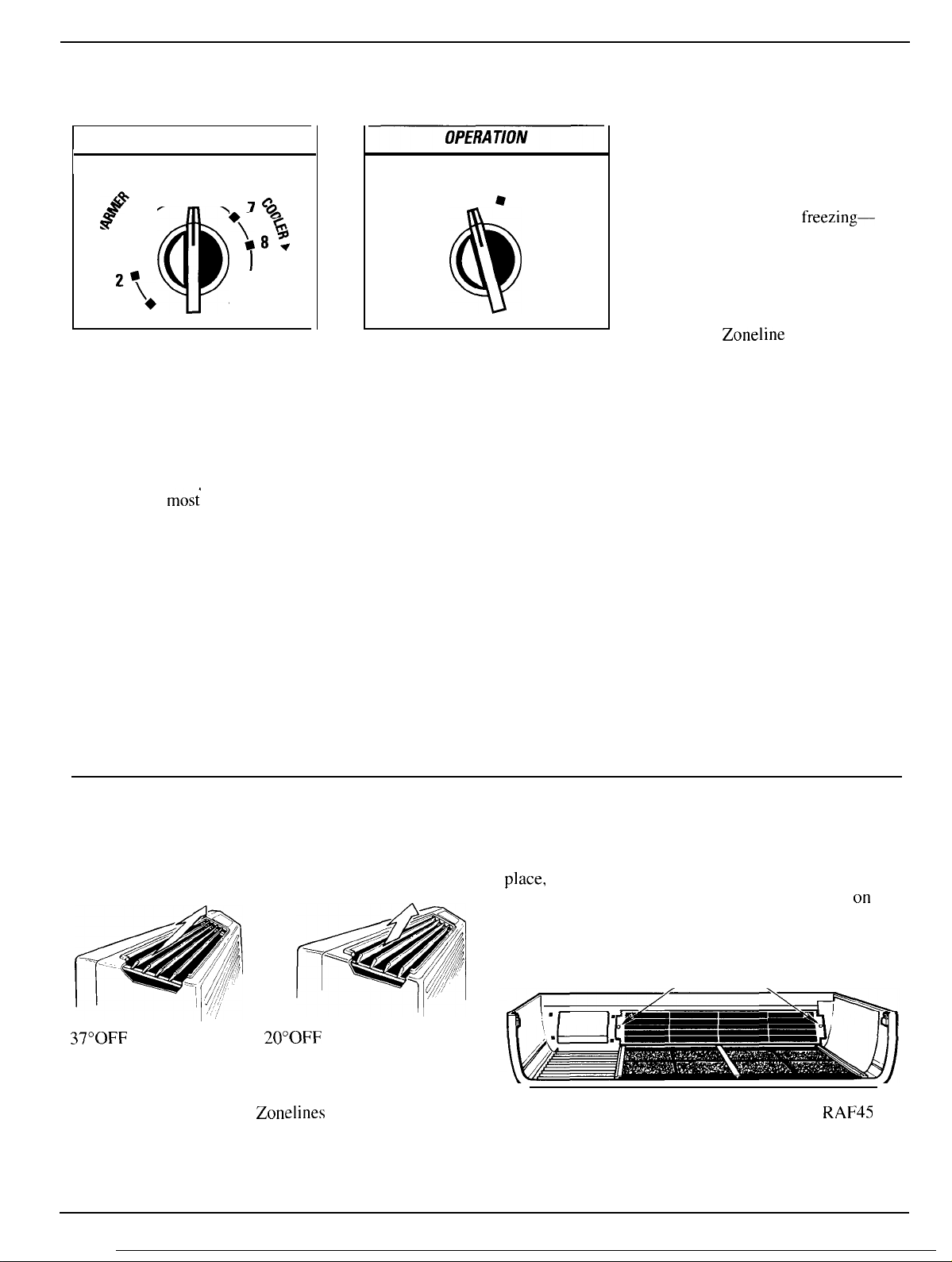
Thermostat Control
The thermostat knob is used to
control the room temperature. The
unit automatically cycles on and
off to maintain room temperature.
A comfortable temperature will be
maintained in
control is set at about “5” or “6.”
For cooler temperatures, turn the
control to a higher number.
For warmer temperatures, turn the
control to a lower number.
mos{
rooms when the
STOP FAN
LO HEAT ●
HI HEAT
●
●
@
8
●
LO COOL
●
HI COOL
Operation Switch
HI HEAT provides heating with
high fan speed operation.
LO HEAT provides heating with
low fan speed operation.
STOP
setting stops heating or
cooling.
connected to the unit
Freeze Sentinel still functions.
FAN provides fan operation
without cooling or heating.
HI COOL provides cooling with
high fan speed operation.
LO COOL provides cooling with
low fan speed operation.
However, power remains
and the
About Your Heat Pump...
Heat pumps can save money by
removing heat from the outside
air—even when the outside
temperature is below
and releasing that heat indoors.
To get the best from your heat
pump, don’t change the room
thermostat very often. Raising
the heat setting 2-3 degrees may
cause the
to use its electrical heating
elements in order to reach the
new temperature setting quickly.
The electric heating elements use
much more electricity than heat
pumps and cost more to operate.
Zoneline
freezing—
heat pump
Discharge Air Louvers
The angling of the discharge air may be adjusted from
the factory setting of 37° off vertical, to a setting 20°
off vertical.
37°0FF VERTICAL
NOTE: For high mounted
Room Cabinet.
20°0FF VERTICAL
Zonelines
where greater room cabinet louver adjustments are required, order the
To reposition the louvers, remove the room cabinet and
remove the 2 screws that hold the louver section in
place,
rotate the louver section 180° (end for end),
replace the screws and put the room cabinet back
air conditioner. Textured face of louver section must be
toward the room side.
LOUVER SCREWS
/\
on
RAF45
the
3
Page 4
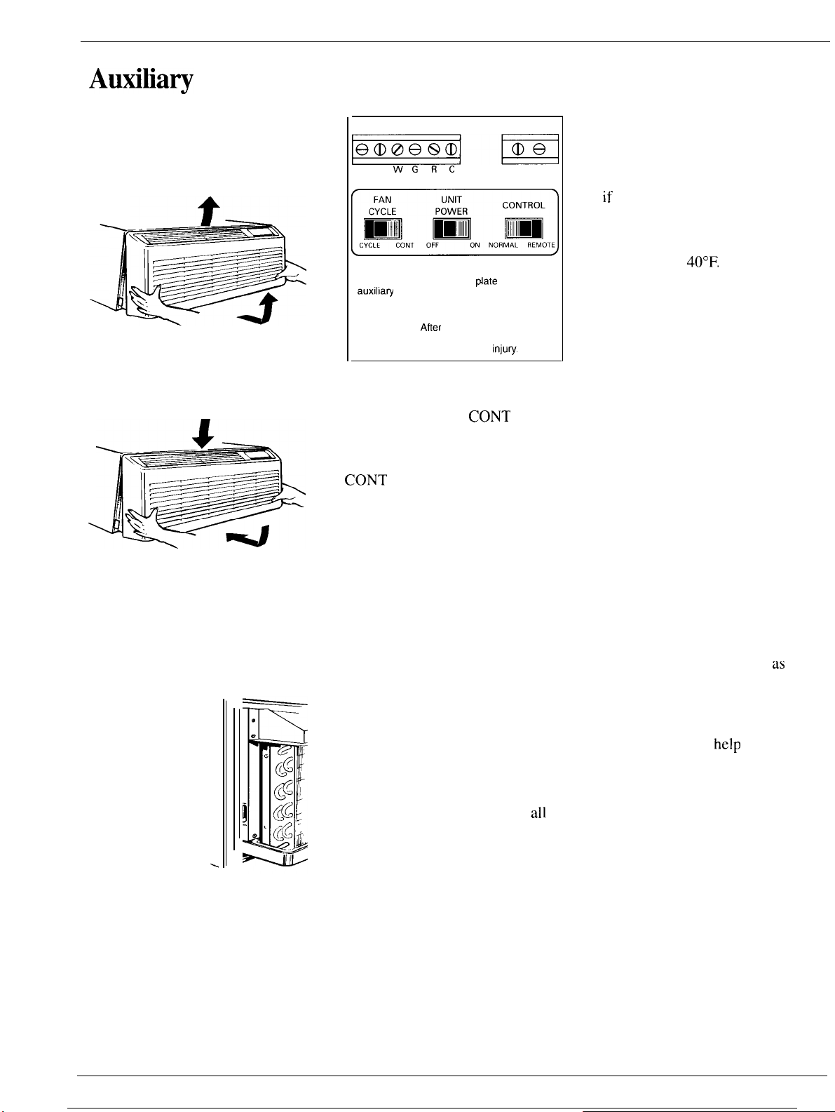
Autitia~
Controls
Additional controls are located
behind the room cabinet.
Access to the controls is obtained
by removing the room cabinet.
To remove the room cabinet,
grasp it at both sides, pull it out to
release it from the tabs. Then lift it
up and pull forward.
To replace the room cabinet,
position tabs at top of room cabinet
over the rail at top of chassis. Push
the room cabinet inward until it
snaps into place.
Ventilation Control
The ventilation
control lever is
located at the lower
left side of the unit,
behind the room
cabinet.
This knob is set
at CLOSE at the
factory. When in
this position, the
vent door is closed
and only indoor air is circulated
by the air conditioner.
Switching the knob to OPEN
opens the vent door to allow
outdoor air to enter the room.
However, leaving the vent door
OPEN reduces heating or cooling
effectiveness and increase
operating costs.
-
‘
CLASS 2 REMOTE
-m
BY
WGRC
=
The CLASS 2 REMOTE and CDC terminals
are located behind a cover
auxilia~
controls. To remove the plate,
remove and save the screws that hold the
plate to the unit.
IMPORTANT:
completed, replace the plate to prevent
damage to the unit or personal
Afier
@ate
the wire connections are
CDC
above the
inju~.
Fan Cycle Switch
This switch is set at
the factory to provide continuous
fan operation in cool or heat
modes. Leaving the switch in the
CONT setting allows continuous
circulation of room air and
will result in a more balanced
temperature throughout the room.
If you want the fan to cycle on
and off with the compressor or
resistance heater, set the switch
at CYCLE.
CONT
at
Unit Power Switch
This switch controls power to the
cool, heat or fan modes. When set
at ON it allows the unit to operate
in the cool, heat or fan modes.
If this switch is set at OFF, the
unit will not operate in any modes
but the Freeze Sentinel will
still function.
Caution: The Unit Power Switch
is not a power disconnect. If
power must be disconnected from
the unit, remove the line cord plug
from the wall outlet, or remove the
fuses, or turn off the circuit
breakers at the power panel.
all
Freeze Sentinel
The Freeze Sentinel sensor helps
prevent plumbing damage due to
sub-freezing temperatures—even
if you have turned the operation
switch to STOP. The sensor
automatically turns on the heater
and fan if the room temperature
falls to about
40°F.
You do not have to do anything to
activate the Freeze Sentinel. It will
work as long as power to the unit
has not been interrupted.
Remote Control
The unit may be controlled either
by the controls on the unit or by
changing the CONTROL switch to
REMOTE and connecting the unit
to a remote thermostat.
See Installation Instructions.
Central Desk
Control (CDC)
The unit may be connected to a
Central Desk Control system by
connecting the wires from the
central control system to the CDC
terminals located on the panel
behind the room cabinet. These
terminals may also be used
interface for other systems used to
control the unit such as infrared
detectors, key-activated systems,
etc. The Freeze Sentinel remains in
an active mode to
help
against low temperature damage
even though the unit may be OFF
at the central control location.
See Installation Instructions.
as
protect
an
4
Page 5
Care and Cleating
Temperature Limiter
The normal range of the thermostat
control is approximately
to
85°F.
The control range may be
narrowed by the use
temperature limiting screws
located behind the control panel.
Stop
Scre~s
● ● Knob Shaft
4
the
u’
“
left
of the knob shaft
●
w
To set the limiting screws:
1.
Remove the room cabinet.
2. Pull both THERMOSTAT knob
and the OPERATION knob
shafts and remove the control panel.
3. Remove and relocate either or
both stop screws on the exposed
control box cover.
[War;est)
To limit the maximum heating
temperature, move the stop
screw
at
clockwise. To limit the minimum
cooling temperature, move the stop
screw on the right counterclockwise.
Make sure the stop arm is between
the stop screws as shown.
Because actual room temperature
can be affected by location and
installation as well as outdoor
weather conditions, you may want
to experiment to determine the
stop screw locations that best meet
your temperature requirements.
After adjusting the limiting
screws, reinstall the control panel,
knobs and room cabinet.
of the
60°F.
stop
Arm
●
off
the
(Cotiest)
For peak operating efficiency and
durability of your air conditioner
follow these necessary Care and
Cleaning instructions regularly.
~rn
the
Zoneline
before cleaning.
off
Room Cabinet & Case
Wash the room cabinet and case
finish with mild soap or detergent
and lukewarm water.
Outdoor Coil
The
coil
on the outdoor side
of the unit should be checked
periodically and cleaned if
clogged with dirt or soot from
the atmosphere. If extremely dirty,
it may need to be professionally
steam cleaned, a service available
through many GE service outlets.
Base Pan
In some installations dirt or other
foreign matter may be blown into
the unit from the outside and settle
in the base pan (the bottom of the
unit).
Check the base pan periodically
and clean it out, if necessary.
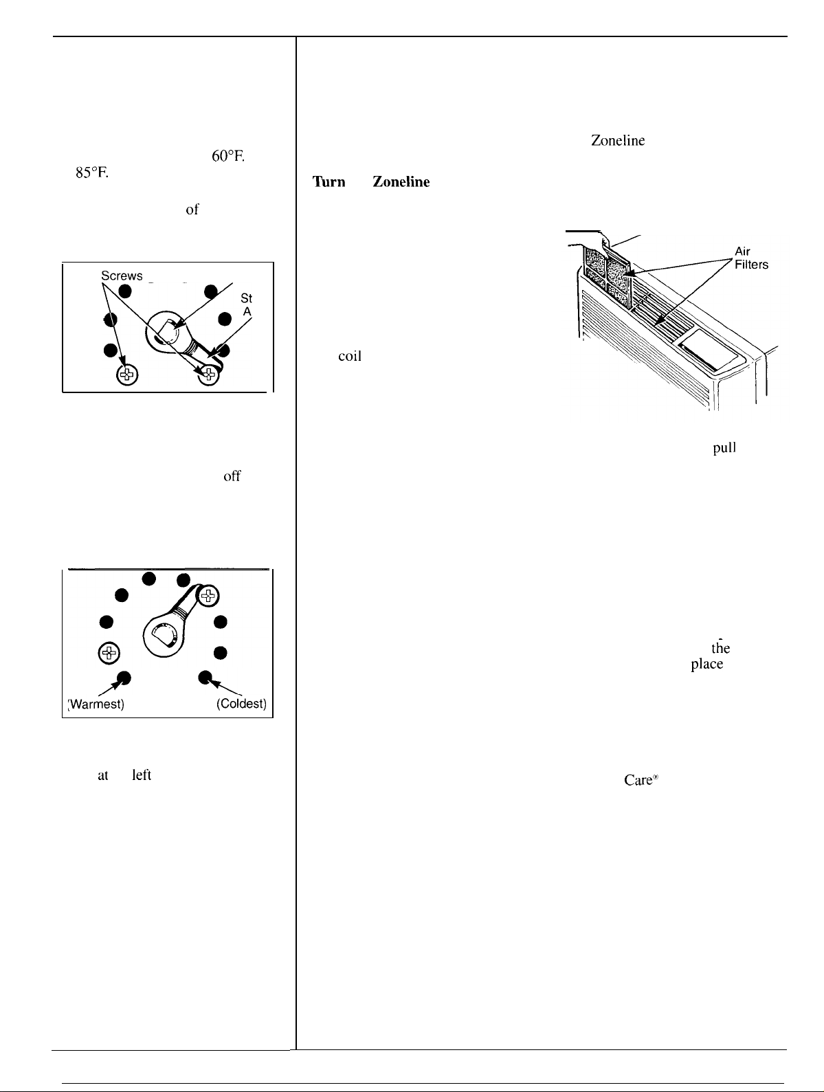
Air Filters
The
Zoneline
should be cleaned at least every
30 days.
The two air filters are located in
front of the air louvers.
\
To remove the air filters, grasp
the top of the filters and
straight up and out of their slots.
Vacuum the filters on the dirty
side or wash them with running
water.
cleaner side of the filter to drive out
dust and lint. Allow the filters to dry
thoroughly before replacing them.
Note: Do not operate the air
conditioner without the filters in
place. If a filter becomes torn or
damaged it should be replaced
immediately Operating
without the filters in
damaged filters will allow dirt and
dust to reach the indoor coil and
reduce the efficiency of the unit.
Replacement filters are available
from your GE Dealer, Factory
Service Center or authorized
Customer
To reinstall the air filter after
cleaning, make sure the word
FRONT is facing out. Insert the
bottom of each filter in their slots
and push down into place.
air filters inside
pull
Run water through from the
t;e
unit
place
or with
Care”’
servicers.
5
Page 6

BEFORE YOU BEGIN
Read these instructions completely and carefully.
lMPORTANT–Observe
ordinances.
lNSTALLER—Be
sure to leave these instructions
with the Consumer.
CONSUMER—Keep these instructions for future
reference.
all governing codes and
CAUTION
Before starting the installation, the power to
the direct connect wiring should be OFF.
THE GE
Exterior Grille/Louver**
ZONELIN~
Room Cabinet*
ELECTRICAL REQUIREMENTS
FOR PERSONAL SAFETY:
●
FOIIOW
National Electrical Code (NEC) and
local codes, ordinances and regulations. All
wiring — including installation of receptacle,
must be in accordance with these codes.
●
This unit must be properly grounded.
●
Do
not use an extension cord with this unit.
●
NEC
requires permanent connection for
installations over 250 volts.
●
NEC requires units controlled by NEC Class 2
low voltage remote controls to be permanently
connected.
●
protective devices
installations are specified on the nameplate of
each.
●
Aluminum
problems—consult a qualified electrician.
● Disconnect power to the air conditioner before
servicing by:
1.
Removing the power cord from the wall
receptacle, if it has one.
2. Removing the branch circuit fuses or turning
the circuit breakers off at the panel.
building wiring may pose special
acceptable for
Zoneline
Wall Case
Chassis
Power
Connection
* Shipped with the chassis
** Check essential elements list on chassis
*** Line cord connection shown only as example
WALL CASE & GRILLE
1.
The
RAB
70 or 77 Wall Case must be properly
installed per instructions packed with the case.
2. Remove the corrugated stiffener and the
outdoor protective panel. Use the slit in the
outdoor panel as a handhold and push out.
Protective
Panel
Slit
/
TOOLS NEEDED
Phillips screwdriver
Flat Blade screwdriver
6
/
Stiffener
H/
3. Install the Exterior Grille from the room side
per instruction packed with the grille.
Page 7

I
INSTALLATION INSTRUCTIONS
(cont,nue,)
I
NEWDUCTEDINSmLLAVON
If
this unit is to be installed in a new ducted
application using a duct adaptor kit, the kit must
be installed before the chassis is placed in the wall
case. The Installation Instructions are packed with
the kit.
MISVNGDUCTEDINSWILAVON
Replacement of an existing ducted unit may require
different components. Request this information
from your sales representative.
I
INSMLLATION
1. Remove the room cabinet by pulling out at the
bottom to release it, then lift it up to clear the rail
along the chassis top.
lNS~LLATION
3. Reinstall the room cabinet by hooking the top
over the rail along the chassis top, then pushing it
in at the bottom.
POWER
The power connection kit must be used to supply
power to the
is determined by the voltage, the means of
electrical connection and the amperage of the
branch circuit.
Connections of 208 or 230 volt circuits maybe
with a line cord kit or a permanent connection kit.
Connections of 265 volt circuits must be with a
permanent connection kit.
Electrical Wiring Wall
Outlets 230/208 volt
CONNECVON
Tandem 15 amp
(continued)
Zoneline chassis. The appropriate kit
2.
Slide the chassis into the wall case and secure
with four screws through the chassis flange holes.
Case
●
:
o
Perpendicular 20 amp
.:
o
Lsrge
tandem 30 amp
.:
PERMANENT
CONNECTION KIT
&
%
o
NEC requires permanent connection for
installations over 250 volts.
All wiring, including installation of the receptacle,
must be in accordance with the National Electrical
Code and local codes, ordinances and regulations.
(continued next page)
7
Page 8

I
INSTALLATION INSTRUCTIONS
(contln.e,)
POWER
230/208 Volt
Line Cord Kits
RAK315 Tandem
RAK320
RAK330*
230/208 Volt
Permanent
Connection Kits
RAK41 5/415L
RAK420/420L
RAK430/430L*
Kits ending in “L” have flexible conduit to reach from the kit to the knockout hole (above right side inspection
plate) in the RAK 203 Sub-Base.
265 Volt
Permanent
Connection Kits
RAK51 5/515LF
RAK517/517LF 15 Amp TD Fuse
RAK520/520LF
RAK530/530LF*
Kits ending in
plate) in the
*Not recommended for use on 6000
of 3.45
CONNEC70N(continue@
Wall Plug
Configuration
Perpendicular
Large Tandem
Circuit Protective Device
15 Amp
20 Amp TD Fuse or Breaker
30 Amp TD Fuse or Breaker
Circuit Protective Device
15 Amp
20 Amp TD Fuse
30 Amp TD Fuse 5.00
“LF”
have flexible conduit to reach from the kit to the knockout hole (above right side inspection
RAK203
KW
at 230 volts and 3.7 KW at 265 volts.)
Sub-Base and have an Integral Fuse.
TD Fuse or Breaker
TD Fuse
BTUH Units. (If this connection kit is used it will provide a maximum heat
Circuit Protective Device
15 Amp
20 Amp
30 Amp Fuse or Breaker
TD Fuse or Breaker
TD fuse or Breaker
Heater Wattage
@
230/208 Volts
2.55/2.09
3.45/2.82
5.00/4.10
Heater Wattage
@
265 Volts
1.70
KW
KW
3.00
3.70
KW
KW
KW
KW
KW
Heater Wattage
@
230/208 Volts
2.55/2.09
3.45/2.82
5.00/4.10
KW
KW
KW
ADJUSTMENTS AND AUXILIARY CONTROLS AVAILABLE WITH THE ROOM CABINET REMOVED
DISCHARGEAIRLOUVERS
The angling of the discharge air maybe adjusted from
the factory setting of 37° off vertical, to a setting 20°
off vertical.
37 ‘OFF VERTICAL
NOTE: For high mounted Zonelines where greater room cabinet louver adjustments are required, order the
I
RAF45
Room Cabinet.
20:OFFVERTICAL””
‘
To reposition the louvers, remove the room cabinet
and remove the 2 screws that hold the louver section
in place, rotate the louver section 180° (end for end),
re~lace the screws and ~ut the room cabinet back on
the air conditioner. Textured face of louver section
must be toward the room side.
LOUVER SCREWS
/\
Page 9

I
INSTALLATION INSTRUCTIONS
(cont,nue,)
TEMPERATURE LIMITING
The normal range of the thermostat control is
approximately
may be narrowed by the use of the temperature
limiting screws located behind the control panel.
Repositioning the screw on the left will limit the
maximum temperature about
in a clockwise rotation; the screw on the right will
limit the minimum temperature when moved
counterclockwise. Limiting the maximum and
minimum settings prevents users from turning
the controls to extreme positions. Restrictions to
full rotation of the thermostat knob may require
explanation to the room occupant that unit
will provide comfortable conditions at
settings allowed.
To access the limiting screws, remove the room
cabinet, remove the Thermostat knob and the
Operation knob by pulling each knob off its shaft
and removing the control panel. Set the limiters to
the desired setting, replace the control panel and
the control knobs. If the original settings do not
allow sufficient room temperature control the
limiter screws may have to be repositioned.
stop
Link
‘warm:)%
If the temperature limiters are used it is
recommended that the limiters be set no higher
than the second hole from the original bottom
position. This provides an operating range
between approximately
maximize the benefit of the temperature limiting it
may be necessary to adjust the limiter screws
seasonally to allow unoccupied rooms to be
maintained at moderate temperatures (i.e., heating
season temperatures limited between
75°F.;
between
●
k
cooling season temperatures limited
60°F.
to
85°F.
‘ /Tapped
7:o’~:Tos’at
Stop location as shipped
66°F.
85°F.
and
65°F.).
The control range
3°F. for each hole
Holes (10)
and
79°F.
In order to
60°F.
and
VENTILATION CONTROL
The VENTILATION control lever is located at the
lower left side of the unit, behind the room cabinet.
This lever controls the
vent door and is set in the
CLOSE position at the
factory so outdoor air will
not enter the room through
the unit and only indoor
air is circulated by the
air conditioner.
Moving the lever to OPEN
opens the vent door and
draws outdoor air through
the air conditioner and into
the room. Leaving the vent
door OPEN during extreme
temperature conditions reduces heating or cooling
effectiveness and increases operating
costs.
WATER DRIPPAGE
Water dripping from the wall case during heat
pump operation is to be expected. In heat pump
operation, water condenses on the outdoor coil
and frost melts, causing drippage.
It can be eliminated by attaching a drain kit to the
unit and routing the water through a drain system.
If the unit has an Internal Condensate Removal
(lCR) feature, the drippage should be minimal.
Installation of a drain system is recommended if no
drippage of condensate to the outdoors is allowable.
9
Page 10

3100 SERIES
Auxiliary Control Panel
CLASS 2 REMOTE
e@Oe
BY
FAN
CYCLE
-1
CYCLE CONT OFF ON NORMAL REMOTE
E
The CLASS 2 REMOTE and CDC terminals are
located behind a cover plate above the
controls. To remove the plate, remove and save
the screws that hold the plate to the unit.
IMPORTANT: After the wire connections are
completed, replace the plate to prevent damage
to
the unit or personal injuy.
WGRC
80
POWER
m]
uNIT
Coc
me
CONTROL
m
auxiliay
REMOTE CONTROL – 3100 SERIES
The unit may be controlled either by the unit
mounted controls or by changing the “CONTROL”
switch located behind the room cabinet to
“REMOTE” and connecting the unit to a 6 wire
Class 2 remote thermostat (GE Model
or RAK 152A or equivalent) the unit may be
converted to remote thermostat control.
2
STAGE HEAT
1 STAGE COOL
MANUAL THERMOSTAT
RAK147A
CENTRAL DESK CONTROL
The unit may be connected to a switch at the front
desk. When the switch is OPEN the unit is operable.
When the switch is CLOSED, the unit is made
inoperable. Connect the wires from the central
control system to the “CDC” terminals located on
the panel behind the room cabinet. Follow the
recommended wire sizing in the table below. Two
wires must be used from each CDC switch to each
individual unit. Do
CDC wiring. A 24 volt transformer is contained
within the unit and no external voltage should be
applied to the unit through the CDC terminals. These
terminals may also be used as an interface for other
systems used to control the unit, such as infrared
detectors, key-activated systems, etc. The Freeze
Sentinel remains in an active mode to help protect
against low temperature damage even though the
unit may be “OFF” at the central control location.
Recommended
Control Installation
Wire Size #
#24
#22
#20
#18
#16
not use a common buss in the
Wire Size for Central Desk
AWG
Maximum Allowable Length
400 ft.
600 ft.
900 ft.
1500 ft.
2000 ft.
I
BY
WGRC
CLASS 2 REMOTE
LOW VOLTAGE
TERMINAL ON ZONELINE
FREEZE SENTINEL
The unit is equipped with a sensor that
automatically turns on the resistance heater and
fan if the room temperature, as sensed at the unit,
drops to approximately 40° F. and will shut the
heater off when the temperature reaches about
520 F. The Freeze Sentinel system helps prevent
damage due to sub-freezing temperatures and will
operate regardless of the mode setting of the unit.
Freeze Sentinel is active as long as power to the
unit has not been interrupted.
FAN CYCLE SWITCH
This switch is set at CONT at the factory to provide
continuous fan operation in cool or heat modes.
Leaving the switch in the CONT setting allows
continuous circulation of room air and will result in a
more uniform temperature throughout the room.
Setting the switch at CYCLE will cause the fan to cycle
on and off with the compressor or resistance heater.
UNITPOWER SWITCH
This switch controls power to the cool, heat and fan
modes. It is set in the ON position at the factory to
allow the air conditioner to operate in these modes.
If this switch is set in the OFF position the air
conditioner will not operate in any modes but the
Freeze Sentinel will still function.
Caution: The UNIT POWER switch is not a
power disconnect.
disconnected from the unit remove the line cord
plug from the outlet, or remove the fuses, or turn
off the circuit breakers at the building power panel,
or unplug the power connector from the chassis.
If all power must be
10
Page 11

Energ-Saving
Tips
● Keep the air filter clean.
(See Care and Cleaning section.)
● For most efficient operation,
keep vent in closed position.
● Don’ t
too cold. Whenever possible, turn
the unit on before the room heats
up or cools off. If you don’t, the air
conditioner will take longer to
produce the desired comfort
condition.
● Keep windows and doors
closed. Conditioned air escapes
when they’re open.
● Keep furnace floor registers and
cold air returns closed when
cooling is desired. Conditioned air
can easily escape through them.
●
Don’t let drapes or furniture block
the front of the air conditioner. This
will restrict air
is operating.
● It’s best to operate your air
conditioner at high speed during
extremely hot or cold weather.
● Keep outdoor condenser coil
clean. (See Care and Cleaning
section.)
●
Turn air conditioner off during
vacations or extended absences.
let
the room get too hot or
flow
when the unit
~
~
Questions?
Use This Problem Solver
~
PROBLEM
AIR CONDITIONER
DOES NOT OPERATE
AIR CONDITIONER
“DOES NOT COOL
OR HEAT AS IT
SHOULD”
“BURNING” ODOR
AT START OF
HEATING
OPERATION
OPERATING SOUNDS
POSSIBLE CAUSE
● Power cord not plugged in, fuse
blown,
or
circuit breaker tripped.
● Unit is waiting for compressor overload
protector to reset.
● Curtains, blinds or furniture blocking the front
of the air conditioner will restrict air flow.
● Thermostat Control may not be set high
enough. Turn the control to a lower or higher
number. (Note: In some installations, the
Thermostat Control cannot be turned all the
way to “1“ or “10.” This is normal. Do not
attempt to force the control beyond its stopping
points.)
● Dirty air filter blocking air flow. Filter
should be cleaned at
least
every 30 days. See
instructions in cleaning section.
● Room may have been very hot or very cold
when the air conditioner was first turned on.
Allow time for it to cool down or warm up.
●
Ventilation control may be set at OPEN
position, allowing outside air to enter the room.
●
Dust on the surface of the heating
element can cause “a burning” odor
at the beginning of the heating operation.
This odor should quickly fade.
● Relay clicks may be heard when the
compressor or fan cycles on and off. This is
normal.
● Fan runs continuously when the unit
is operating unless the Fan Cycle Switch
behind the room cabinet is set at CYCLE.
Then the fan cycles on and off with the heater.
OUTDOOR WATER
DRIPPING DURING
HEATING OPERATION
● Water dripping from the outside of the
heat pump is normal during heating operation.
Drain kits are available. Water can be routed
through a drain system to eliminate the
problem.
If you need more help.. call, toll free:
GE Answer Center
(p
800.626.2000
consumer information service
11
Page 12

Page 13

Notes
13
Page 14

Notes
Page 15

Wdll
With the purchase
Be There
ofyour
new GE appliance, receive the
assurance that if you ever need information or assistance
from GE, we’ll be there. All you have to do is call–toll-free!
GEAnswer Center@
8006262000
In-Home Repair
Service
80ME$ARES
(80M32-2737)
AGEconsurner selwi[:eI>rofkssion:~l”
will provide
scheduled
for
you. Many
company-operated” locations
you service today or tomorrow, or at
your convenience
weekdays,
days).
know your appliance inside and outso most repairs
(me
visit.
expert
repair service,
at a time
9:()()
Our
f’actory-trained technicians
that.’s
convenient
(;E (lonsunler
(7:()()
a.m. to
a.m. to
2:()()
p.m. Satur-
can be handled in just
Semice
offer
7:()()
p.m.
Service Contracts
80&626-2224
YOLI
can have the secure fkeling
(;E (lonsunler
there
after your warranty expires. l)ur-
chase a
ranty is still in
a substantial
year
conl.ract, you’re
service at today’s prices.
Service will still be
(;E
contrac[ while your war-
efi’ect and you’ll receive
discount. With a nlultiple-
2issLncd offuture
Lhat
Whatevcryoul
rnaj( )r
appliance,
inf;)rnlat.ion ser~i(e is available to
help.
Your call–and
will he answered promptly
coLlrteously.”
time.
(;E
open
24
Telecommunication
question
(;E1
And you can call any
Answer
hours a day, 7 days a week.
(lenter”
Detice
aboLll
Answer
yOLn- question-
ancl
service is
for
tie
(lentel
Deaf
any(;
Patis andAccessories
80&626-2002
Individu~ qufified
o-
appliances
parts or accessories sent directly to
their
home.
‘I-he (1E
vides access
all
(;E (Jenuine
fidly warranted. VISA, Master(;ard
and Discover cards are accepted.
User maintenance instructions
contained in this
dures intended to be performed by
any user. Other servicing
shodd
vice personnel. Caution must be
exercised, since improper servicing
may cause unsafe operation.
to over
be referred to
to service their
can
have needed
parts system pro-
47,()()()
parts.. and
Renewal Parts arc
boo~et cover proce-
generdy
qudfied
ser-
s,cmoNA.A
...,.. .,-..,..,,..,.,-.=..
... W. L.. LW.S”..,”C,..,.
kr
Customers With
.“.,.
..., =,.,
Special Needs...
Upt)n request,
controls”
and a
brochure
barriel--free kitchen for persons with
limited
fi-c>c
or speech who have access to a TDD
01- a conventional Teletypewriter
call 800-TDD-(;MC;”
to requesl
mobility. T()
of’rharge,
(lonsumers with impaired hearing
C;E
will provide Braille
for a variety
to
assisl
call
800.tj26.2000.
infk~rmation
of’(;E
appliances,
in planning a
obt>~in
these items,
(800-833-4:322)”
or service.
may
Page 16

YOUR GE ZONELINE AIR CONDITIONER
WARRANTY
Save
I
proof of original purchase date such as
your sales slip or
cancelled
check to establish warranty period.
WHAT IS COVERED
FULL ONE-YEAR WARRANTY
For one year from date of original
purchase, we will provide, free of
charge, parts and on-site service
labor to repair or replace
the
room air conditioner that
of
~a~~:~tecause
FULL-FIVE YEAR WARRANTY
For five years from the date of
original purchase, we will provide,
free of charge, parts and on-site
sewice labor to repair or replace
anypati
system
evaporator and all connecting
tubing) that fails because of a
manufacturing defect.
of a manufacturing
of the sealed refrigerating
(the compressor, condenser,
any part
This warranty is extended to
the original purchaser and any
succeeding owner for products
purchased for use in the 48
mainland states, Hawaii and
Washington,
warranty is the same except that it
is LIMITED because you must pay
to ship the product to the service
shop or for the
travel costs to your home.
All warranty
provided by our Factory Service
Centers or by our authorized
Customer
normal working hours.
Call I-800-GE CARES
(1-800-432-2737).
D.C. In Alaska the
sewice technician’s
sewice will be
Care” sewicers during
For each of the above warranties:
Transportation expense to and
from a service shop and shop
service labor if required will be free
of charge.
WHAT IS NOT COVERED
● Service trips to teach you
how to use the product.
Read your Use and Care material.
If you then have any questions
about operating the product please
contact your dealer or our
Consumer Affairs office at the
address below, or call, toll free:
GE Answer Center
800.626.2000
consumer information service
Some states do not allow the exclusion or limitation of incidental or consequential damages, so the above limitation or exclusion
may not apply to you. This warranty gives you specific legal rights, and you may also have other rights which
To know what your legal rights are in your state, consult your local or state consumer affairs office or your state’s Attorney General.
(o
● Improper installation.
If you have an installation
problem,
or if the air conditioner is
of improper cooling capacity for the
intended use, contact your dealer
or installer. You are responsible for
providing adequate electrical
connecting facilities.
● Replacement of house fuses or
resetting of circuit breakers.
● In commercial locations labor
necessa~ to move the unit to a
location where it is accessible for
service by an individual technician.
● Failure of the product resulting
from modifications to the product or
due to unreasonable use including
failure to provide reasonable and
necessary maintenance.
● Failure due to corrosion on
models not corrosion-protected.
c
Damage to product caused
by improper power supply voltage,
accident, fire, floods or acts of God.
WARRANTOR IS
RESPONSIBLE FOR
CONSEQUENTIAL DAMAGES.
va~
from state to state.
NOT
I
Pub.
6/92
No.
CG
49-7251
Warrantor: General Electric Company
If further help is needed concerning this warranty, write:
Manager—Consumer Affairs, GE Appliances, Louisville, KY 40225
Zoneline(’)
Heat Pump
31OO
serie~
 Loading...