

Page 1
Model number:
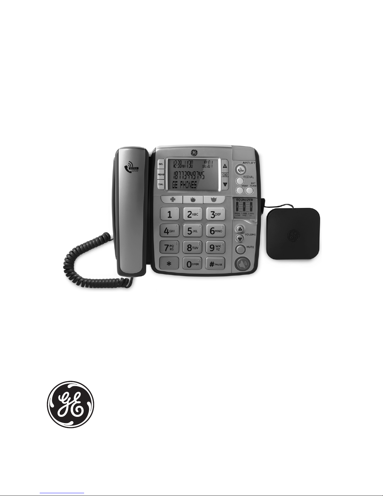
30234
AMPLIFIED SPEAKERPHONE WITH
VIBRATING ALERT
Page 2

Thank you for choosing GE!
Register your product
Please take a moment to register your product online. Just go to
www.gephones.com and click “register here” from the home page. Provide
your email address and receive product updates, special oers, or discounts
on future purchases.
* It will not diminish your warranty rights if you choose not to register.
Assistance and more information
Retain your sales receipt as proof of purchase in the event warranty service is
necessary.
For product assistance or for more information about accessories, visit our
website at www.gephones.com or call our customer service center at
1-877-394-9775.
Attach your sales receipt here.
Page 3

Introduction
Important installation guidelines ........1
Getting started
Parts checklist ..............................................2
Telephone base layout .............................3
Back and side views ..................................4
Installing backup batteries ....................5
Installing on a desk or table ..................6
Installing on a wall .....................................7
Settings
Display language ........................................8
Contrast ..........................................................8
Local area code ...........................................8
Telephone operation
Speakerphone ..............................................9
Placing a call .................................................9
Answering a call ....................................... 10
Amplified audio.........................................10
Equalizer ..................................................... 10
Volume..........................................................11
Neckloop Jack ...........................................11
Mute ............................................................... 11
Vibrating alerter ....................................... 11
Flash ..............................................................11
Redial .............................................................11
Memory
To store a number in memory ...........12
To add a pause to a memory
location ......................................................12
To change a stored number ...............12
To dial a number from memory ........12
To dial from the Programmable
Emergency Call Buttons ....................13
Chain dialing from memory ................ 13
Caller ID
Call Waiting with Caller ID ................... 14
Caller ID record ......................................... 14
Review caller ID records ....................... 15
Dial from caller ID records ...................15
Caller ID display messages ................. 16
Store caller ID record into
memory ..................................................... 16
To replace a stored caller ID record
in memory ................................................ 16
Delete a caller ID record in caller ID
record ......................................................... 17
Delete all caller ID records in caller
ID record ...................................................17
Appendix
Troubleshooting guide ..........................18
General Product Care ............................20
Equipment Approval Information ....21
Important Safety Instructions ...........24
Limited Warranty .....................................27
Index .............................................................. 29
Table of contents
Page 4
Introduction
CAUTION: When using telephone equipment, there are basic safety
instructions that should always be followed. Refer to IMPORTANT
SAFETY INSTRUCTIONS on page 24 for more details.
This phone is intended for use by those individuals with mild to severe
hearing loss. This product is designed with special volume and frequency
controls, including a three-band equalizer for adjusting the audio tone.
AMPLIFY OVERRIDE CAUTION
When the AMPLIFY Override switch is set to ON, the telephone increases the
volume of the handset much higher than that of conventional telephones
and could be uncomfortable for individuals with normal hearing. Turn the
AMPLIFY Override switch to OFF if the volume level is uncomfortable.
Please read this manual very carefully before using your 30234 and keep
it for future reference. If you have any questions or problems, consult the
Troubleshooting guide on page 18 for help. Or you may visit our website
at www.gephones.com for additional information.
Important installation guidelines
• Avoid sources of noise and heat, such as motors, fluorescent lighting,
microwave ovens, heating appliances and direct sunlight.
• Avoid areas of excessive dust, moisture and low temperature.
• Never install telephone wiring during a lightning storm.
• Never install telephones or jacks in wet locations.
• Never touch non-insulated telephone wires or terminals, unless the
telephone line has been disconnected at the network interface.
THE LIGHTNING
FLASH AND ARROW
HEAD WITHIN
THE TRIANGLE IS
A WARNING SIGN
ALERTING YOU
OF “DANGEROUS
VOLTAGE” INSIDE
THE PRODUCT.
CAUTION
RISK OF ELECTRICAL SHOCK, DO NOT OPEN
CAUTION: TO REDUCE THE
RISK OF ELECTRICAL SHOCK,
DO NOT REMOVE COVER (OR
BACK). NO USER SERVICEABLE
PARTS INSIDE. REFER
SERVICING TO QUALIFIED
SERVICE PERSONNEL.
THE EXCLAMATION
POINT WITHIN
THE TRIANGLE IS
A WARNING SIGN
ALERTING YOU
OF IMPORTANT
INSTRUCTIONS
ACCOMPANYING
THE PRODUCT.
WARNING: TO PREVENT
FIRE OR ELECTRICAL
SHOCK HAZARD, DO
NOT EXPOSE THIS
PRODUCT TO RAIN OR
MOISTURE.
1
Page 5
Getting started
2
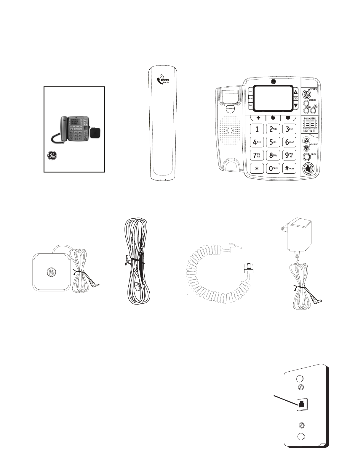
Parts checklist
Your telephone package includes the items shown below.
Telephone jack requirements
To use this phone, you need an RJ11C type
modular telephone jack installed on your line.
If you do not have a modular jack, call your
telephone service provider to find out how to have
one installed. If you have DSL high speed Internet
service, a DSL filter is required (not included).
Contact your DSL service provider for more
information about DSL filters.
Telephone base
User’s manual
Vibrating Alerter
Telephone
line cord
Handset
coiled cord
Power adapter
Handset
Modular
telephone
jack
Model number:
30234
AMPLIFIED SPEAKERPHONE WITH
VIBRATING ALERT
Page 6
Getting started
3
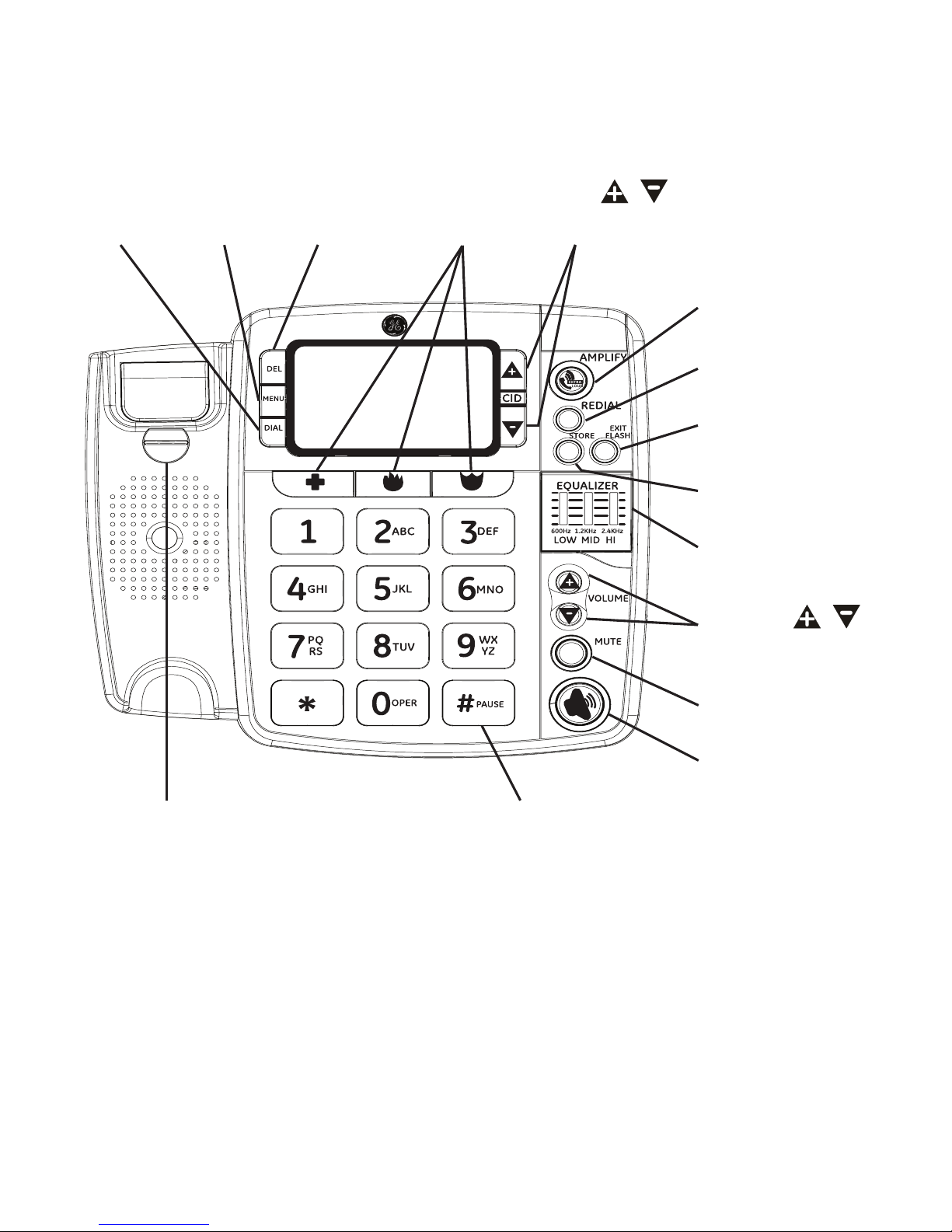
Telephone base layout
Rotating
handset tab
for desk/wall
mounting
DEL
button
MENU
button
DIAL
button
CID /
buttons
AMPLIFY
button
REDIAL button
EXIT/FLASH
button
STORE button
TONE
EQUALIZER
MUTE button
SPEAKER
button
#/PAUSE button
VOLUME /
buttons
Programmable
Emergency Call
buttons
Page 7
Getting started
4
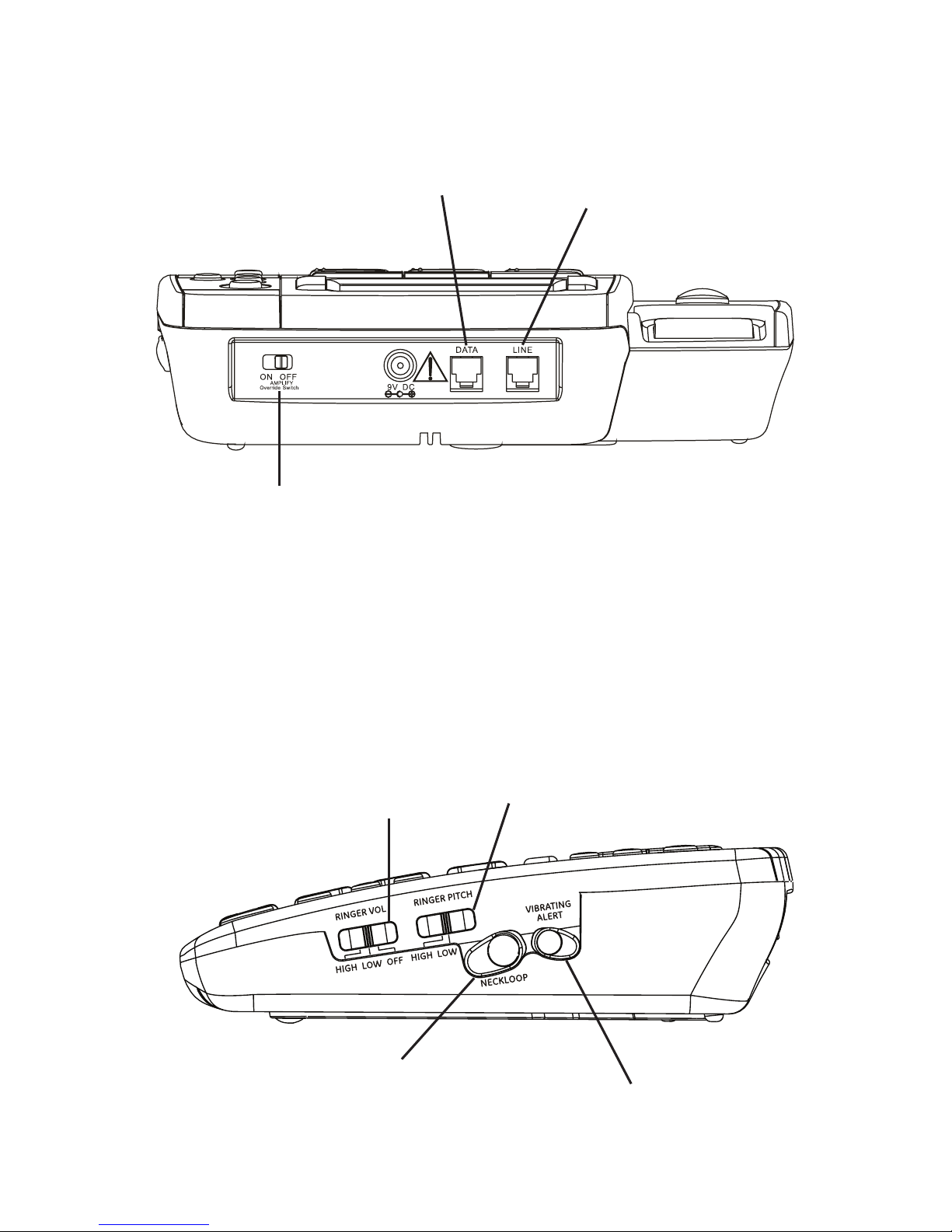
Back and side views
Telephone
line jack
DATA jack for another
phone or data modem
AMPLIFY Override Switch
BACK view
SIDE view
RINGER VOL
(HIGH/LOW/OFF)
switch
RINGER PITCH
(HIGH/LOW) switch
NECKLOOP jack
(neckloop not included -
see page 11 for more
information)
VIBRATING ALERT jack
See Important Safety Instructions on page 24.
AMPLIFY OVERRIDE CAUTION
When set to “ON”, the Amplify Override switch increases the volume of the handset
much higher than that of conventional telephones and could be uncomfortable for
individuals with normal hearing. Turn the Amplify Override switch to the “OFF” position
if the volume level is uncomfortable.
Page 8
Getting started
5
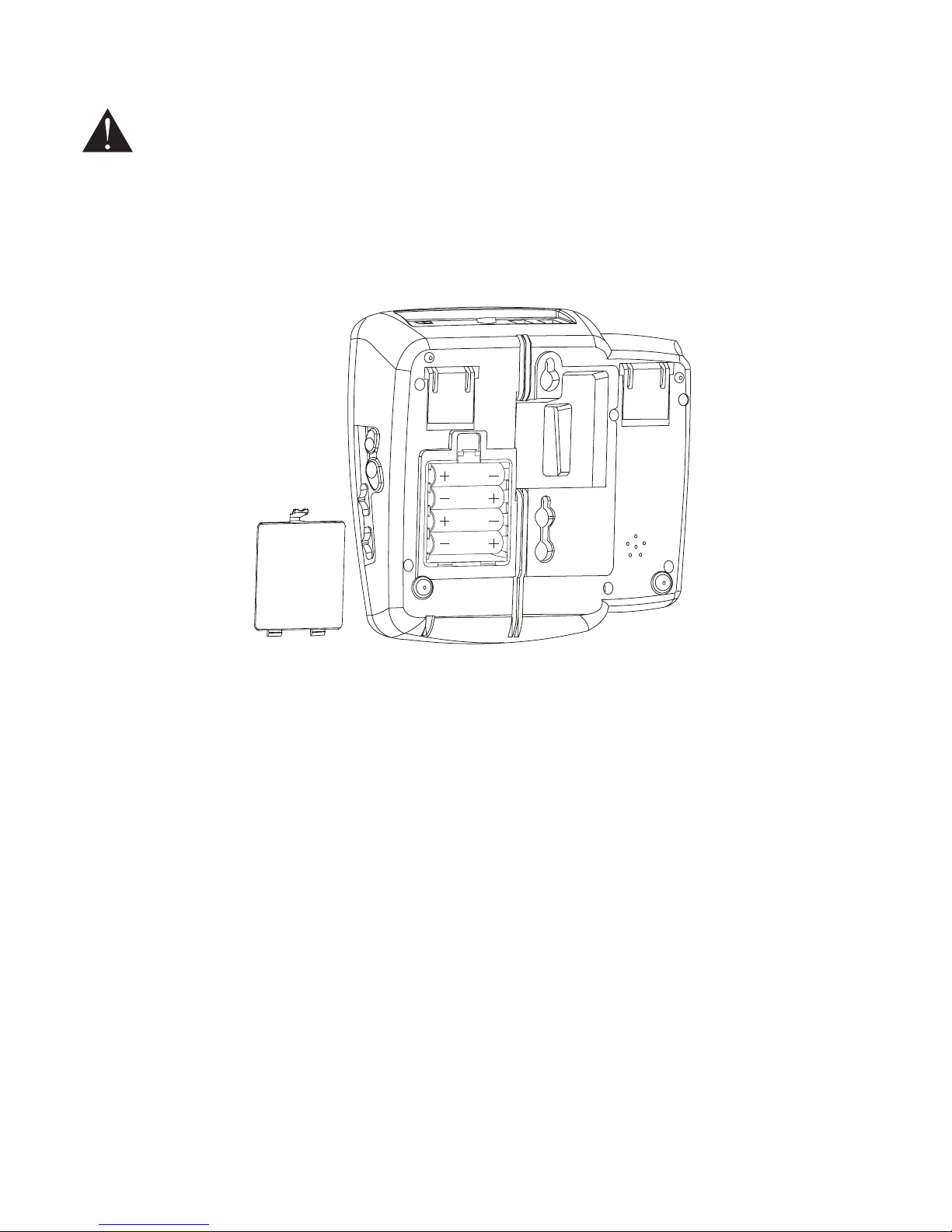
Installing backup batteries
CAUTION: Disconnect the telephone cord from the wall outlet before
installing or replacing the batteries.
In case of a power outage, the phone uses 4 AA alkaline batteries (not
included) for backup power, incoming voice amplification, and visual ringer
functions.
NOTE: If no batteries are installed, the low battery icon will flash on the screen.
1. Unplug the power adapter and the telephone line before installing
batteries.
2. Press the tab to release the battery compartment cover on the bottom of
the base.
3. Insert 4 AA-size alkaline batteries as shown on the engraving in the
battery compartment.
4. Replace the battery compartment cover.
5. Re-attach the power adapter and the telephone line cord to the unit.
NOTE: To prevent product damage from battery leakage, remove the batteries if
storing the unit for more than 30 days.
Page 9
Getting started
6
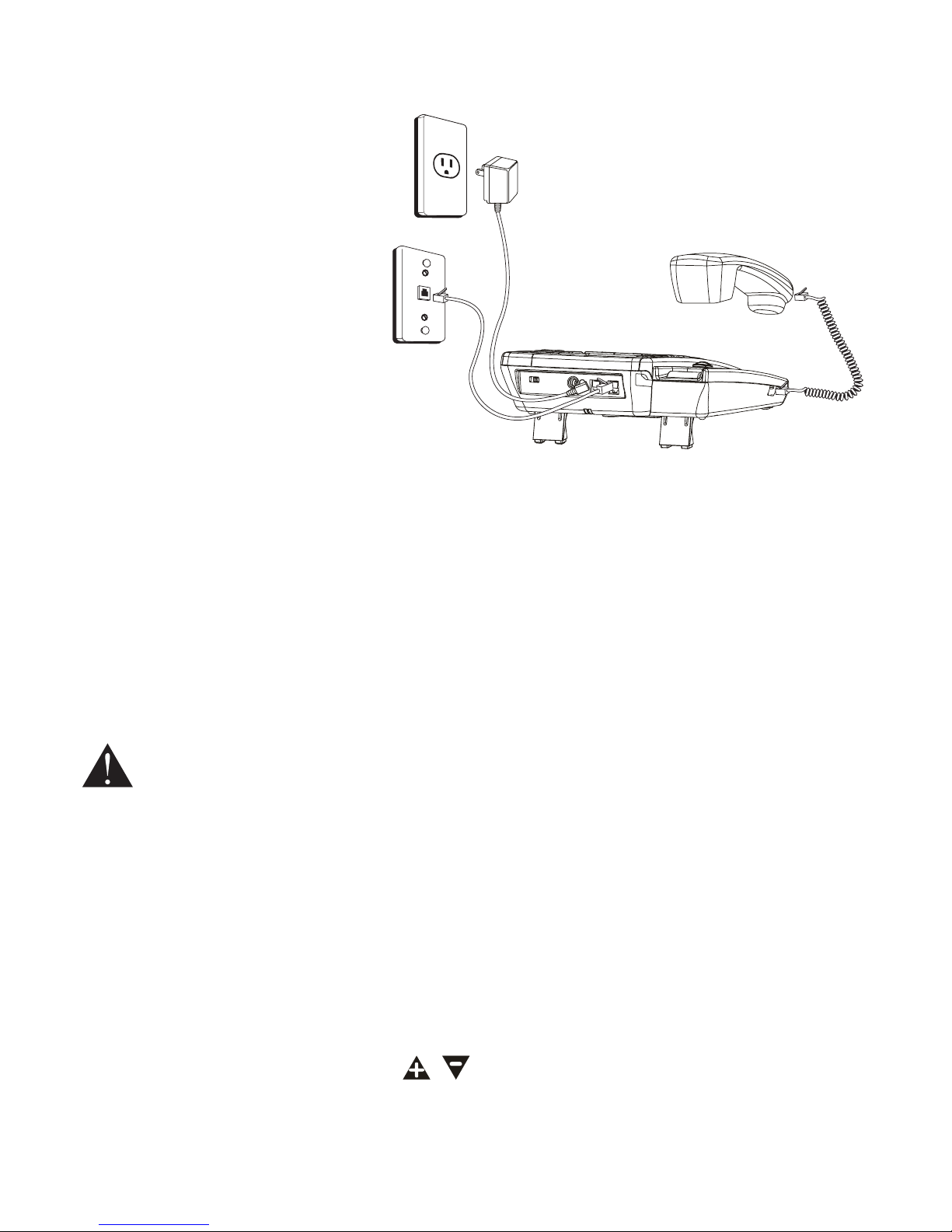
Installing on a desk or table
1. Choose an area near a
telephone modular jack
(RJ11C), and place your
telephone on a level
surface, such as a desktop
or tabletop (for wall
mounting, see instructions
on page 7).
2. Plug one end of the
handset coiled cord into
the bottom of the handset
(near the mouthpiece)
and the other end of the cord into the handset jack (on the left side of the
base), then place the handset onto the base cradle.
3. Plug one end of the telephone line cord into the LINE jack at the top of the
base and the other end into a modular jack. Please Note: If you have DSL
high speed Internet service, a DSL filter is required (not included). Contact
your DSL service provider for more information about DSL filters.
4. If you have another device (e.g. an additional telephone or data modem)
that needs to be connected to the telephone line, please connect it to the
DATA jack at the top of the base.
CAUTION: To reduce risk of personal injury, fire, or damage, use only the
power adapter provided with this product. This power adapter is
intended to be correctly oriented in a vertical or floor mount position.
5. Plug the power adapter into an electrical outlet and into the jack engraved
“9V DC” at the top of the base. Do not use an electrical outlet controlled by
a wall switch.
6. You can flip open the kick-stands on the bottom of the base for a better
viewing angle when placed on a desktop.
7. Make sure the rotating handset tab shown on page 3 is rotated to the
DESK position.
8. Adjust the VOLUME buttons ( / ) to the desired listening level. Adjust
the RINGER VOLUME switch to the desired setting: HI, LOW or OFF. You
can also adjust the pitch of the ringer by setting the RINGER PITCH switch
(HIGH/LOW).
Page 10

Getting started
7
The unit is properly installed if you pick up the handset and hear a dial tone.
If you do not hear a dial tone, re-check all installation steps.
Installing on a wall
1. Make sure the rotating handset tab is in
the WALL position (see page 3) and
batteries have been properly installed.
2. Plug one end of the telephone line cord
into the LINE jack at the top of the base.
Please Note: If you have DSL high speed
Internet service, a DSL filter is required
(not included). Contact your DSL service
provider for more information about
DSL filters.
3. Close the kick-stands on the bottom of
the base.
4. Thread the line cord through the groove as shown and plug the end into
the modular telephone jack. Excess telephone line can be tucked into the
recessed area at the bottom of the telephone base.
5. Slip the mounting holes (on the bottom of the base) over the wall plate
posts on the modular jack and slide the unit down firmly into place.
6. Plug the power adapter into the jack engraved “9V DC” at the top of the
base, then plug the other end into an electrical outlet not controlled by a
wall switch.
7. Plug one end of the handset coiled cord into the bottom of the handset
(near the mouthpiece) and the other end of the cord into the handset jack
(on the left side of the base), then place the handset onto the base cradle.
8. Adjust the VOLUME buttons ( / ) to the desired listening level. Adjust
the RINGER VOLUME switch to the desired setting: HI, LOW or OFF. You
can also adjust the pitch of the ringer by setting the RINGER PITCH switch
(HIGH/LOW). The unit is properly installed if you pick up the handset and
hear a dial tone. If you do not hear a dial tone, re-check all installation
steps.
Page 11

8
Settings
Display language
You can select ENGLISH (ENG), FRANCIS (FRA) or ESPAÑOL (ESP) as the
display language.
1. Press MENU until ENG FRA ESP shows on the screen.
2. Press CID ( / ) to move the cursor to select a language.
3. Press MENU again to save.
4. Press EXIT/FLASH to return to the idle mode.
Contrast
This feature allows you to adjust the contrast of the screen.
1. Press MENU until CONTRAST shows on the screen.
2. Press CID ( / ) to select level 1, 2, 3 or 4,
3. Press MENU again to save.
4. Press EXIT/FLASH to return to the idle mode.
Local area code
This telephone can use programmed area codes to determine the number
format to display when a valid Caller ID signal is received. Numbers that
match the local area code are displayed as seven digits and are used for
dialing back previous numbers. Entering your local area code will also help
you immediately know if the call is local or long distance when viewing the
caller ID records in the display.
1. Press MENU until LOCAL AREA CODE shows on the screen.
2. Use the dial pad keys to enter your 3-digit area code. If you make a
mistake, press DEL to delete a number and enter again.
3. Press MENU again to save.
4. Press EXIT/FLASH to return to the idle mode.
Page 12

9
Telephone operation
Speakerphone
For hands-free operation and convenience, this unit is equipped with a
speakerphone.
For best speakerphone performance, avoid the following:
• Areas with high background noise (the microphone might pick up these
sounds and prevent the speakerphone from going into the receiving mode
when you finish talking).
• Surfaces aected by vibration.
• Recessed areas such as in a corner, under a cupboard, or next to a
cabinet, which can generate an echo eect.
Note the following guidelines when using the speakerphone:
• The speakerphone works similarly to a two-way radio (also called FRS or
“Walkie-Talkies”) in that you can only listen or talk at one time.
• Stay within 2 to 3 feet of the phone so that you can be clearly heard by the
caller.
• You can adjust the speaker volume by adjusting the VOLUME ( / )
buttons while the speakerphone is in use.
• The speakerphone indicator lights when the speakerphone is in use.
Placing a call
Handset
1. Lift the handset and listen for a dial tone.
2. Dial the number.
3. Return the handset to the base to end the call.
Speakerphone
1. Press SPEAKER on the base and listen for a dial tone.
2. Dial the number.
3. Press SPEAKER again to end the call.
Page 13

Telephone operation
10
Answering a call
NOTE: Make sure the RINGER VOL switch is set to HIGH or LOW, or the phone will not
ring. The visual ring indicator will flash on all settings.
Amplified audio
You may press AMPLIFY to temporarily increase the volume of the handset
receiver or speakerphone during a call. Press AMPLIFY again to return to
normal volume level. The volume level will also return to normal after you end
the call.
If you want the amplifier automatically turned on whenever you lift the
handset, slide the AMPLIFY Override switch on the back of the unit to ON.
AMPLIFY OVERRIDE CAUTION
When set to “ON”, the Amplify Override switch increases the volume of the
handset much higher than that of conventional telephones and could be
uncomfortable for individuals with normal hearing. Turn the Amplify Override
switch to the “OFF” position if the volume level is uncomfortable.
Equalizer
This feature allows you to change the audio tone of the handset to best suit
your hearing.
1. To activate the equalizer, press AMPLIFY after you lift the handset, or any
time during a call. The AMPLIFY indicator lights up.
2. Lift the EQUALIZER cover and slide the switches up or down to adjust the
tone.
3. Your customized tone settings will be used each time when you turn on
the AMPLIFY feature.
Handset
1. Lift the handset when the telephone rings.
2. Return the handset to the base to end the call.
Speakerphone
1. Press SPEAKER to answer a call when the telephone rings.
2. Press SPEAKER again to hang up.
You may switch between speakerphone and normal handset use anytime
during a call.
Speakerphone to Handset - Lift the handset to disable speakerphone. The
speakerphone indicator turns o.
Handset to Speakerphone - Press SPEAKER, and then return the handset to
the base. The speakerphone indicator turns on and the handset is disabled.
Page 14

Telephone operation
11
Volume
You can adjust the volume of both the handset and the speakerphone.
While using the handset or speakerphone, press VOLUME ( / ) to adjust
the handset volume from level 1 to 4 or the speakerphone volume from level
1 to 8. An error tone emits when the volume is adjusted to the maximum or
minimum.
Neckloop Jack (Sold Separately)
The base is equipped with a 3.5mm Neckloop jack for an optional Neckloop
device (an assistive listening device normally available through hearing
specialty manufacturers and retailers). For information about Neckloop
devices including how to purchase, contact your physician or hearing
specialist.
NOTE: The handset does not operate when a Neckloop device is plugged into the base
unit. The speakerphone can be used as normal.
Mute
Press MUTE to mute the microphone during a call. Press MUTE again
to resume conversation. A conversation can be muted while using the
speakerphone, handset or neckloop.
NOTE: This feature will be canceled when you switch between speakerphone,
neckloop and handset.
Vibrating alerter
To use the vibrating alert feature, simply plug the included vibrating alerter
into the VIBRATING ALERT jack on the right side of the base. Place the alerter
in a clean, dry location where you can feel it vibrate such as on a chair or
under a pillow, being careful when routing the cord. When the telephone
rings, the alerter will vibrate with each ring of the phone.
Flash
Press EXIT/FLASH to use custom calling services such as call waiting or call
transfer, which are available through your telephone service provider.
Redial
You may redial the last number you called by pressing the REDIAL button
after you lift the handset or press SPEAKER.
NOTE: The redial feature retains the last phone number you dialed (maximum of
32 digits) during your last call. If you pressed any numbers after dialing the phone
number (for example, when accessing a voice-menu system), those numbers are also
recorded in the redial memory.
Page 15

12
Memory
You can store a maximum of 13 entries in the memory for quick dialing. You
can store three numbers in the Programmable Emergency Call Buttons and
ten numbers in the dial pad keys (0-9).
IMPORTANT NOTE: The programmable Emergency Call buttons have
icons for quick identification, but they are not pre-programmed. You
must program these buttons before using them. These buttons can be
programmed with any telephone number you prefer.
To store a number in memory
1. Press STORE when the telephone is not in use. The screen then shows
LOCATION?.
2. Select a memory location from the dial key pad (0-9) or one of the
Programmable Emergency Call Buttons.
3. Press STORE and then enter the number using the dial key pad.
4. Press STORE and then enter the name using the dial key pad.
5. Press STORE again to save the record. The screen shows OK when the
entry is successfully stored.
To add a pause to a memory location
You can insert a dialing pause in the dialing sequence when storing a number
requiring a pause.
1. Follow the steps as To store a number in memory above.
2. Press and hold #PAUSE until a P displays in the dialing sequence where a
pause is required (the pause time when dialing out is approximately four
seconds - if additional time is needed, press and hold #PAUSE again).
To change a stored number
Follow the same steps as To store a number in memory above. The new
numbers will overwrite the existing numbers.
To dial a number from memory
1. Lift the handset or press SPEAKER when the telephone is not in use.
2. Press DIAL followed by the key pad memory location (0-9).
Page 16

Memory
13
To dial from the Programmable Emergency Call Buttons
1. Lift the handset or press SPEAKER.
2. Press the desired Programmable Emergency Call Button.
IMPORTANT NOTE: The Programmable Emergency Call Buttons have
icons for quick identification, but they are not pre-programmed. You
must program these buttons before using them. These buttons can be
programmed with any telephone number you prefer.
Chain dialing from memory
This feature allows you to initiate a dialing sequence from numbers stored
in the memory while you are on a call. This feature is useful if you wish to
access another numbers (such as bank account information or long distance
service) from the memory. The following example shows how you can use
chain dialing to make a call through a long distance service.
The Number For Memory Location
Long Distance Access Number 1
Authorization Code 2
Frequently called long distance number 3
1. Lift the handset or press SPEAKER.
2. Press DIAL and then press 1.
3. When you hear the access tone, press DIAL and then press 2.
4. At the next access tone, press DIAL and then 3.
Page 17

14
Caller ID
IMPORTANT: To use caller ID features, you must subscribe to either the
standard name/number caller ID service or call waiting with caller ID
service. You must subscribe to call waiting with caller ID service to know
who is calling while you are on a call.
This unit receives and displays information sent by your telephone service
provider. This information may include the phone number, date and time; or
the name, phone number, date and time. The caller ID information is sent to
the telephone between the first and second ring.
PM
#
NEW
CALL
10/20
10:28
317-555-1234
FRED PAGE
03
Caller
ID name
Caller ID
phone
number
Number
of calls
Date
Time
Call Waiting with Caller ID
If you subscribe to call waiting with caller ID service from your telephone
service provider, a call waiting alert sounds when you receive a second
incoming call while you are already on a call. Call Waiting with Caller ID
information will only be displayed on the handset that is in use when the
second incoming call comes.
When you hear the call waiting beep, press EXIT/FLASH to put the current
call on hold and answer the second incoming call. Press EXIT/FLASH again to
return to the original call.
Caller ID record
Your telephone can store up to 70 most recent call records. When the 71st
call is received, the oldest Caller ID record (1st call) is automatically deleted.
You may review the stored caller ID record any time. Calls received since your
last review show as NEW on the display.
Page 18

Caller ID
15
Review caller ID records
To scroll through caller ID records:
1. Press CID ( ) to review the latest Caller ID record.
2. Press CID ( ) to review the oldest Caller ID record first.
Dial from caller ID records
1. Press CID ( / ) to display the desired record.
2. Press the DIAL button and the screen shows PHONE. Then lift the handset
or press SPEAKER to dial the number.
NOTE: Depending on (a) how the incoming caller’s phone number is formatted when
it is received, and (b) whether or not you previously pre-programmed your local area
code into the setting menu, you may need to adjust the format of the caller ID record
before calling. Press DIAL repeatedly to show dierent dialing options. PICKUP or ADJ
displays on the screen while you are changing the phone number format.
Available formats include:
Number of digits Descriptions Example
11 digits long distance code “1 ”
+3-digit area code
+7-digit telephone number.
1-317-888-8888
10 digits 3-digit area code +
7-digit telephone number.
317-888-8888
7 digits 7-digit telephone number. 888-8888
Page 19

Caller ID
16
Caller ID display messages
Display Status
BLOCKED CALL The caller of the incoming call is registered as Private
Number and the caller ID information is withheld.
CALL WAITING A second incoming call is waiting on the line.
LOW
ON steadily when battery power level is low; flashing
when no batteries are installed.
NO CALLS The caller ID memory is empty.
START/END You are at the beginning or the end of the caller ID
log.
UNKNOWN
CALLER
The incoming call does not have caller ID service or
your area does not support this service. If UNKNOWN
CALLER appears along with a calling number, the
name information for that number was not available.
Store caller ID record into memory
NOTE: Be sure to format the CID entries correctly before storing them. Stored entries
can be replaced but not edited.
1. Press CID ( / ) to scroll to the desired caller ID record when the
telephone is not in use.
2. Press STORE and the screen shows LOCATION?
3. Use the dial key pad to enter a memory location (0-9) or press one of the
Programmable Emergency Call Buttons to store the number in that
memory location.
4. Press STORE three times to save the record. The screen shows OK to
confirm.
NOTE: The system cannot store any caller ID records that contain nonnumerical
information. The screen shows UNABLE TO STORE when you are trying to save them
into the memory.
To replace a stored caller ID record in memory
Repeat step 1 to step 4 in Store caller ID record into memory above.
Page 20

Caller ID
17
Delete a caller ID record in caller ID record
1. Press CID ( / ) to select the desired CID record when the telephone is
not in use.
2. Press DEL to delete the caller ID record.
NOTE: Press EXIT/FLASH to return to the idle mode.
Delete all caller ID records in caller ID record
1. Press CID ( / ) to display any caller ID record.
2. Press and hold DEL until DELETE ALL? shows on the display.
3. Press DEL again to delete all records. The screen shows NO CALLS.
NOTE: Press EXIT/FLASH to return to the idle mode.
Page 21

18
Appendix
Troubleshooting guide
Problem Cause/solution
Phone is not working • Unplug all power sources including line cord,
power cords and batteries. Allow the unit to
remain completely unplugged for 1 to 2 minutes.
• Reinstall all power sources, place the handset on
the base, wait for 1 to 2 minutes and then test the
unit again.
• Test the connection by swapping line cords with
another telephone.
• Test the jack by moving the product in question to
another phone jack, or try a working telephone in
the jack where the defective product is located.
No dial tone • Check installation: make sure the telephone line
cord is connected to the base unit and a modular
phone jack (RJ-11).
• Try disconnecting and reconnecting the handset
cord into the handset and base to ensure proper
connection.
• Check the switch hook. Make sure it fully extends
when the handset is lifted from the base.
• You must have touch-tone service on your line
to use this phone. If you do not know what type
of service you have, check with your telephone
service provider.
• Unplug the phone, wait for 30 seconds, and plug
the phone back in.
• Connect another phone to the same modular jack;
if the second phone does not work, the problem
might be with your wiring or local service.
• Place the handset on the base for at least 20
seconds.
Page 22

Appendix
19
Problem Cause/solution
Static or noise on
line
• If you have DSL high speed Internet service, be
sure you have a DSL filter installed at every jack
where a phone is installed.
• Check your telephone line cord and handset coiled
cord for wear and tear. If the line cord is worn or
cut, replace with another cord.
• Check for noise on other telephones on the same
line. Disconnect all phones and plug one phone
in at a time. If the noise/static persists, it could
be the problem of the jack; if the noise/static
persists on all jacks, it could be the problem of the
telephone line. Check with your telephone service
provider (charges may apply).
Phone does not ring • Make sure the RINGER VOL switch is set to LOW
or HI.
• You may have too many extension phones on your
line. Unplug some extension phones.
• Check for a dial tone. If there is no dial tone, see
solutions for No dial tone.
Cannot dial from
memory locations
• Make sure you stored the memory buttons
correctly. Try restoring the memory location. Be
sure to include any dialing prefixes like “1” and/
or an area code just as you would if dialing the
number manually (see Memory on page 12).
• Make sure the telephone is properly installed. Lift
the handset and listen for a dial tone. If you don’t
hear a dial tone, recheck or repeat the installation
steps.
Cannot be heard by
other party
• Make sure the telephone line cord is securely
plugged in.
• Make sure extension phones are not in use at the
same time you are using the phone. It is normal
for the volume to drop when additional extension
phones are used at the same time.
Page 23

Appendix
20
Problem Cause/solution
Low handset or
speaker volume
• Check the handset receiver or speaker volume
settings.
General Product Care
• Avoid putting the phone near heating appliances and devices that generate
electrical noise (for example, motors or fluorescent lamps).
• Avoid dropping the phone and other rough treatment.
• Clean the phone with a soft cloth.
• Never use strong cleaning agents, paint thinner, abrasive powder, alcohol,
or other chemical products to clean the unit. Doing so may damage the
finish.
• Retain the original packaging in case you need to ship the phone at a later
date.
• DO NOT expose to direct sunlight or moisture.
Page 24

Appendix
21
Equipment Approval Information
Your telephone equipment is approved for connection to the Public Switched
Telephone Network and is in compliance with parts 15 and 68, FCC Rules
and Regulations and the Technical Requirements for Telephone Terminal
Equipment published by ACTA.
1. Notification to the Local Telephone Company
On the bottom of this equipment is a label indicating, among other
information, the US number and Ringer Equivalence Number (REN) for
the equipment. You must, upon request, provide this information to your
telephone company.
The REN is useful in determining the number of devices you may connect
to your telephone line and still have all of these devices ring when your
telephone number is called. In most (but not all) areas, the sum of the RENs
of all devices connected to one line should not exceed 5. To be certain of the
number of devices you may connect to your line as determined by the REN,
you should contact your local telephone company.
A plug and jack used to connect this equipment to the premises wiring
and telephone network must comply with the applicable FCC Part 68 rules
and requirements adopted by the ACTA. A compliant telephone cord and
modular plug is provided with this product. It is designed to be connected to
a compatible modular jack that is also compliant. See installation instructions
for details.
Equipment Approval Information
• This equipment may not be used on coin service provided by the telephone
company.
• Party lines are subject to state taris, and therefore, you may not be able
to use your own telephone equipment if you are on a party line. Check with
your local telephone company.
• Notice must be given to the telephone company upon permanent
disconnection of your telephone from your line.
• If your home has specially wired alarm equipment connected to the
telephone line, ensure the installation of this product does not disable your
alarm equipment. If you have questions about what will disable alarm
equipment, consult your telephone company or a qualified installer.
US Number is located on the cabinet bottom.
REN Number is located on the cabinet bottom.
Page 25

Appendix
22
2. Rights of the Telephone Company
Should your equipment cause trouble on your line which may harm the
telephone network, the telephone company shall, where practicable, notify
you that temporary discontinuance of service may be required. Where
prior notice is not practicable and the circumstances warrant such action,
the telephone company may temporarily discontinue service immediately.
In case of such temporary discontinuance, the telephone company must:
(1) promptly notify you of such temporary discontinuance; (2) aord you
the opportunity to correct the situation; and (3) inform you of your right to
bring a complaint to the Commission pursuant to procedures set forth in
Subpart E of Part 68, FCC Rules and Regulations. The telephone company
may make changes in its communications facilities, equipment, operations
or procedures where such action is required in the operation of its business
and not inconsistent with FCC Rules and Regulations. If these changes are
expected to aect the use or performance of your telephone equipment, the
telephone company must give you adequate notice, in writing, to allow you to
maintain uninterrupted service.
Interference Information
This device complies with Part 15 of the FCC Rules. Operation is subject
to the following two conditions: (1) This device may not cause harmful
interference; and (2) This device must accept any interference received,
including interference that may cause undesired operation. This equipment
has been tested and found to comply with the limits for a Class B digital
device, pursuant to Part 15 of the FCC Rules. These limits are designed to
provide reasonable protection against harmful interference in a residential
installation. This equipment generates, uses, and can radiate radio frequency
energy and, if not installed and used in accordance with the instructions, may
cause harmful interference to radio communications. However, there is no
guarantee that interference will not occur in a particular installation. Privacy
of Communications may not be ensured when using this product.
If this equipment does cause harmful interference to radio or television
reception, which can be determined by turning the equipment o and on, the
user is encouraged to try to correct the interference by one or more of the
following measures:
• Reorient or relocate the receiving antenna (that is, the antenna for radio or
television that is “receiving” the interference).
Page 26

Appendix
23
• Reorient or relocate and increase the separation between the
telecommunications equipment and receiving antenna.
• Connect the telecommunications equipment into an outlet on a circuit
dierent from that to which the receiving antenna is connected.
• If these measures do not eliminate the interference, please consult
your dealer or an experienced radio/television technician for additional
suggestions.
Notice: The changes or modifications not expressly approved by the party
responsible for compliance could void the user’s authority to operate the
equipment.
Hearing Aid Compatibility (HAC)
This telephone system meets FCC standards for Hearing Aid Compatibility.
Page 27

Appendix
24
Important Safety Instructions
Some of the following information may not apply to your particular product;
however, when using telephone equipment, basic safety precautions should
always be followed to reduce the risk of fire, electric shock and injury to
persons, including the following:
1. Read and understand all instructions.
2. Follow all warnings and instructions marked on the product.
3. Unplug this product from the wall outlet before cleaning. Do not use liquid
cleaners or aerosol cleaners. Use a damp cloth for cleaning.
4. Telephones should not be used while you are in a bathtub, shower or
pool. Immersion of the telephone or handset in water could cause an
electrical shock.
5. Slots and openings in the cabinet back or bottom are provided for
ventilation, to protect it from overheating. Do not block or cover these
openings. Do not block the openings by placing the product on a bed,
sofa, rug, or other similar surface. Do not place this product in a built-in
installation unless proper ventilation is provided.
6. Only operate this product from the type of power source indicated on
the marking label. If you are not sure of the type of power supply to your
home, consult your dealer or local power company.
7. Plug the adaptor into an easily accessible electrical outlet near the
equipment.
8. Do not allow anything to rest on the power cord. Do not locate this
product where the cord will be abused by persons walking on it.
9. Do not overload wall outlets and extension cords as this can result in the
risk of fire or electric shock.
10. Never push objects of any kind into this product through cabinet slots as
they may touch dangerous voltage points or short out parts that could
result in a risk of fire or electric shock. Never spill liquid of any kind on the
product.
11. Never spill liquid of any kind on the product.
12. To reduce the risk of electric shock, do not disassemble this product.
If service or repair work is required, take it to a qualified serviceman.
Opening or removing covers may expose you to dangerous voltages
or other risks. Incorrect reassembly can cause electric shock when the
Page 28

Appendix
25
appliance is subsequently used.
13. Do not expose the product to extreme temperatures such as areas
near a hot radiator, stove or in a hot car. Do not place product upon
other consumer electronic products such as; computer monitors, power
amplifiers, etc.
14. Do not place lighted candles, cigarettes, cigars, etc., on or near the
telephone.
15. Never touch uninsulated telephone wires or terminals unless the
telephone line has been disconnected at the network interface.
16. Never install or modify telephone wiring during a lightning storm.
17. Never install jacks or telephones in wet locations.
18. Use caution when installing or modifying telephone lines to prevent
electrical shock and / or fire.
19. Under the following conditions, unplug this product from the wall outlet
and refer servicing to qualified service personnel: A) The power supply
cord or plug is damaged or frayed. B) The product has been exposed to
rain or water. C) The product does not operate normally by following the
operating instructions. D) The product’s cabinet has been damaged.
E) The product exhibits a distinct change in performance.
20. Avoid using a telephone during an electrical-storm. There may be a
remote risk of electric shock from lightning.
21. Do not use the telephone to report a gas leak in the vicinity of the leak.
22. Do not place this product on an unstable cart, stand, or table. The product
may fall, causing serious damage to the product.
23. Only use attachments/accessories specified by the manufacturer.
24. Unplug this apparatus during lightning storms or when unused for long
periods of time.
If your product utilizes batteries, the following additional precautions
should be observed:
1. Use only the type and size battery(ies) specified in the user manual.
2. Do not use this product if the battery door is removed or missing.
3. Replace batteries that appear to be swollen or have damaged wiring.
4. Do not dispose of the battery(ies) in fire. They may explode. Check with
local codes for possible special disposal instructions.
Page 29

Appendix
26
5. Do not open or mutilate the battery(ies). Released electrolyte is corrosive
and may cause damage to the eyes or skin. It may be toxic if swallowed.
6. Exercise care in handling battery(ies) in order not to short out the
battery(ies) with conducting materials such as rings, bracelets, and keys.
The battery(ies) or conductor may overheat and cause burns.
7. Do not attempt to recharge the battery(ies) provided with or identified for
use with this product that are not rechargeable. The battery(ies) may leak
corrosive electrolyte or explode.
8. Do not attempt to rejuvenate the battery(ies) provided with or identified
for use with this product by heating them. Sudden release of the
battery(ies) electrolyte may occur causing burns or irritation to eyes or
skin.
9. When replacing battery(ies), all batteries should be replaced at the same
time. Mixing fresh and discharged batteries could increase internal cell
pressure and rupture the discharged battery(ies). (Applies to products
employing more than one separately replaceable primary battery.)
10. When inserting battery(ies) into this product, the proper polarity or
direction must be observed. Reverse insertion of battery(ies) may result in
leakage or explosion.
11. When inserting battery(ies) into this product, do not twist or pinch the
wires or allow wires to become pinched in battery door.
12. If storing over 30 days, remove battery(ies) from this product because the
battery(ies) could leak and damage the product.
13. Discard “dead” battery(ies) as soon as possible since “dead” batteries are
more likely to leak in a product.
14. Do not store this product, or the battery(ies) provided with or identified for
use with this product, in high-temperature areas. Batteries that are stored
in a freezer or refrigerator for the purpose of extending shelf life should
be protected from condensation during storage and defrosting. Batteries
should be stabilized at room temperature prior to use after cold storage.
15. If your product uses rechargeable battery(ies), charge the battery(ies) only
in accordance with the instructions and limitation specified in the User’s
Guide.
SAVE THESE INSTRUCTIONS
Page 30

Appendix
27
Limited Warranty
One Year Limited Warranty
CCT Tech USA Inc. (CCT), the licensed manufacturer of this GE® branded
product, warrants this product to the original retail purchaser to be free of
material and/or workmanship defects for a period of one year after the date
of original retail purchase. Proof of the original purchase is required to obtain
a remedy under this limited warranty and the product must be returned to
CCT at your expense:
During the limited warranty period, CCT or its authorized service
representative will repair or replace at CCT’s option, without charge, a
materially defective product. We may use new or refurbished replacement
parts. If we replace the product, it may be with a new or refurbished product
of same or similar design. CCT may keep any removed or defective parts,
and/or replaced product. The repaired or replaced product is warranted
for the remainder of the original warranty or 90 days, whichever is greater.
Repair or replacement of this product at CCT’s option is your exclusive
remedy.
This limited warranty only applies to products purchased, used and serviced
in the United States and its territories, or Puerto Rico. If you purchased this
product outside of the United States, its territories or Puerto Rico, contact
your dealer for service information.
This is the only warranty applicable to this product. ALL OTHER WARRANTIES
EXPRESS OR IMPLIED INCLUDING ALL IMPLIED WARRANTIES OF
MERCHANTABILITY OF FITNESS FOR A PARTICULAR PURPOSE ARE HEREBY
DISCLAIMED. CCT IS NOT LIABLE FOR ANY INDIRECT, INCIDENTAL,
CONSEQUENTIAL OR SIMILAR DAMAGES INCLUDING, BUT NOT LIMITED
TO , LOST PROFITS OR REVENUE, INABILITY TO USE THE PRODUCT, OR ANY
OTHER ASSOCIATED EQUIPMENT, THE COST OF SUBSTITUTE EQUIPMENT,
AND ANY CLAIMS BY THIRD PARTIES RESULTING FROM THE USE OF THIS
PRODUCT.
This warranty gives you specific legal rights, and you may have other rights
that vary from state to state. Some states do not allow the exclusion or
limitation of incidental or consequential damages, so the limitations or
exclusions stated above may not apply.
What Is NOT Covered Under This Limited Warranty
• Normal wear and tear or cosmetic damage.
Page 31

Appendix
28
• Damage due to accidents, misuse, physical force, improper installation or
operation, mishandling, neglect, fire, heat, water, humidity, liquids, insect
infestation, or other intrusion.
• Products that have been repaired, altered or modified by anyone other than
CCT or its authorized service representative.
• Problems caused by signal conditions, radio interference, network
reliability, cable or antenna systems.
• Damage caused by use of non CCT accessories or misapplication.
• Products whose serial numbers have been removed, altered or rendered
illegible.
• Products purchased, shipped from, used or serviced outside the United
States.
• Batteries.
• Products used for business, commercial or institutional purposes.
• Damage caused by acts of nature such as, but not limited to, lightening
damage.
• Products returned without valid proof of purchase.
How To Obtain Warranty Service
Call our customer service center at 1-877-394-9775. Our customer service
specialist will assist you in obtaining warranty service. Please have a paper
and pencil handy to write down the warranty service return instructions.
-OR-
You may visit our web site at www.gephones.com for troubleshooting, FAQs,
and information on warranty service.
Page 32

Appendix
29
A
Amplified audio 10
Answering a call 10
B
Back and side views 4
C
Caller ID
delete record 17
dial from record 15
display message 16
replace stored record 16
review record 15
storing into memory 16
Call waiting with Caller ID 14
Chain dialing 13
Contrast 8
D
Display language 8
E
Equalizer 10
Equipment Approval Information 21
F
Flash 11
G
General Product Care 20
I
Important Safety Instructions 24
Installing on a desk or table 6
Installing on a wall 7
Introduction 1
L
Limited Warranty 27
Local area code 8
M
Memory
change a stored record 12
dial from the programmable
emergency call buttons 13
dial from the record 12
Mute 11
N
Neckloop 11
P
Parts Checklist 2
Placing a call 9
R
Redial 11
S
Speakerphone 9
T
Telephone base layout 3
Telephone Jack Requirements 2
Troubleshooting guide 18
V
Vibrating alerter 11
Volume 11
Index
Page 33

visit our website:
www.gephones.com
©2011 CCT Tech USA Inc.
Distributed in the U.S.A. by
CCT Tech USA Inc.
Model 30234
P/N: 905-0234004-00
Version 1 03/2011
Printed in China
is a trademark of General Electric Company and is under license
by CCT Tech USA Inc., Irving, TX 75039
 Loading...