

GE 20870400, GE 2 2-9992 2-9992, 2-9992 Use & Care Manual

We bring good things to life.
2-9992
Messaging System with Caller ID
& Call Waiting
Use & Care Guide

2
Your GE telephone equipment is registered with the
Federal Communications Commission and is in
compliance with parts 15 and 68, FCC Rules and
Regulations.
1 Notification to the Local Telephone
Company
On the bottom of this equipment is a label
indicating, among other information, the FCC
Registration number and Ringer Equivalence
Number (REN) for the equipment. You must, upon
request, provide this information to your
telephone company.
The REN is useful in determining the number of
devices you may connect to your telephone line
and still have all of these devices ring when your
telephone number is called. In most (but not all)
areas, the sum of the RENs of all devices
connected to one line should not exceed 5. To be
certain of the number of devices you may connect to
your line as determined by the REN, you should
contact your local telephone company.
Notes
• This equipment may not be used on coin
service provided by the telephone company.
• Party lines are subject to state tariffs, and
therefore, you may not be able to use your own
telephone equipment if you are on a party line.
Check with your local telephone company.
• Notice must be given to the telephone company
upon permanent disconnection of your
telephone from your line.
2 Rights of the Telephone Company
Should your equipment cause trouble on your
line which may harm the telephone network, the
telephone company shall, where practicable,
notify you that temporary discontinuance of
service may be required. Where prior notice is not
practicable and the circumstances warrant such
action, the telephone company may temporarily
discontinue service immediately. In case of such
temporary discontinuance, the telephone
company must: (1) promptly notify you of such
temporary discontinuance; (2) afford you the
opportunity to correct the situation; and (3)
inform you of your right to bring a complaint to
the Commission pursuant to procedures set forth
in Subpart E of Part 68, FCC Rules and
Regulations.
The telephone company may make changes in its
communications facilities, equipment, operations
of procedures where such action is required in
the operation of its business and not inconsistent
with FCC Rules and Regulations. If these changes
are expected to affect the use or performance of
your telephone equipment, the telephone
company must give you adequate notice, in writing,
to allow you to maintain uninterrupted service.
FCC Number is located on the cabinet bottom
REN number is located on the cabinet bottom
FCC REGISTRATION INFORMATION

3
This device complies with Part 15 of the FCC Rules.
Operation is subject to the following two conditions:
(1) This device may not cause harmful interference;
and (2) This device must accept any interference
received, including interference that may cause
undesired operation.
This equipment has been tested and found to
comply with the limits for a Class B digital device,
pursuant to Part 15 of the FCC Rules. These limits
are designed to provide reasonable protection
against harmful interference in a residential
installation.
This equipment generates, uses, and can radiate
radio frequency energy and, if not installed and used
in accordance with the instructions, may cause
harmful interference to radio communications.
However, there is no guarantee that interference will
not occur in a particular installation.
If this equipment does cause harmful interference to
radio or television reception, which can be
determined by turning the equipment off and on, the
user is encouraged to try to correct the interference
by one or more of the following measures:
WARNING:
TO PREVENT FIRE
OR ELECTRICAL SHOCK HAZARD,
DO NOT EXPOSE THIS PRODUCT
TO RAIN OR MOISTURE.
SEE MARKING ON BOTTOM / BACK OF PRODUCT
CAUTION
RISK OF ELECTRIC SHOCK
DO NOT OPEN
THE EXCLAMATION
POINT WITHIN THE
TRIANGLE IS A
WARNING SIGN
ALERTING YOU OF
IMPORTANT
INSTRUCTIONS
ACCOMPANYING
THE PRODUCT.
THE LIGHTNING
FLASH AND ARROWHEAD WITHIN THE
TRIANGLE IS A
WARNING SIGN
ALERTING YOU OF
"DANGEROUS
VOLTAGE" INSIDE
THE PRODUCT.
CAUTION: TO REDUCE THE
RISK OF ELECTRIC SHOCK,
DO NOT REMOVE COVER
(OR BACK). NO USERSERVICEABLE PARTS INSIDE. REFER SERVICING
TO QUALIFIED SERVICE
PERSONNEL.
INTERFERENCE INFORMATION
• Reorient or relocate the receiving antenna (that is,
the antenna for radio or television that is
“receiving” the interference).
• Reorient or relocate and increase the separation
between the telecommunications equipment and
receiving antenna.
• Connect the telecommunications equipment into
an outlet on a circuit different from that to which
the receiving antenna is connected.
• Consult the dealer or an experienced radio/TV
technician for help.
If these measures do not eliminate the interference, please consult your dealer or an experienced
radio/television technician for additional
suggestions. Also, the Federal Communications
Commission has prepared a helpful booklet, “How
To Identify and Resolve Radio/TV Interference
Problems.” This booklet is available from the U.S.
Government Printing Office, Washington, D.C.
20402. Please specify stock number 004-000-
00345-4 when ordering copies.

4
CALLER ID
This feature allows you to see the number or name and number of the person calling before
you answer the phone.
CALL WAITING
This feature allows you to answer incoming calls while you are talking on the phone.
CALLER ID WITH CALL WAITING
Also known as Type II Caller ID, this feature allows you to see the number or name and
number of a call that beeps in while you are talking on the phone with someone else.
VERY IMPORTANT: The Caller ID with Call Waiting feature of this product is totally dependent
upon your phone company's capabilities. You may subscribe to one service or the other, or even to
both, and this product will function properly.
But to take advantage of the Caller ID with Call Waiting feature, you must call your local phone
company and tell the representative that you have a Caller ID/Call Waiting device that integrates the
two services, regardless of whether or not you already subscribe to one or both services independently.
The phone companies that do have the ability to integrate Call Waiting and Caller ID must program your
telephone line for the feature to work.
Your GE 2-9992 Messaging System with Caller ID and Call Waiting is designed to give you
flexibility in use and high quality performance. You can use this unit with basic telephone
service, but to fully take advantage of its features you must subscribe to the services below:
INTRODUCTION

5
TABLE OF CONTENTS
FCC REGISTRATION INFORMATION 2
INTERFERENCE INFORMATION 3
I
NTRODUCTION 4
CALLER ID 4
CALL WAITING 4
CALL WAITING WITH CALLER ID 4
GETTING STARTED 6
JACK REQUIREMENTS 6
INSTALLATION OPTIONS 7
DESKTOP INSTALLATION 8
WALL INSTALLATION 9
FEATURES AND CONTROLS 11
DISPLAY MESSAGES 12
PROGRAMMING THE SETTINGS 13
GREETINGS 13
DEFAULT GREETINGS 13
TO RECORD A GREETING 13
TO REMOVE A GREETING 13
STANDARD SETTING 14
LANGUAGE 14
DAY, DATE, TIME 14
STANDARD GREETING 14
RING SELECTION 14
SCREEN CALLS 14
TONE 15
MESSAGE LIMIT 15
SECURITY CODE 15
DIAL SETTING 15
LOCAL AREA CODE 15
BLOCKED CALLS 16
ANSWER ON/OFF 16
ADVANCED SETTING 17
CONFIRM DELETE 17
CALLER ID W/ CALL WAITING 17
FACTORY DEFAULT SETTINGS 17
DIGITAL MESSAGING FUNCTIONS 18
RECORDING GREETINGS 18
CHECKING GREETINGS 19
ERASING GREETINGS 19
PLAYING MESSAGES 19
BUTTONS AND CONTROLS 19
AUTO DISCONNECT 19
AUTO TIME/DAY STAMP 19
MEMORY FULL 20
ANSWER OFF 20
RECORDING A MEMO 20
REMOTE ACCESS FUNCTIONS 21
C
ALLER ID FUNCTIONS 23
CID DIAL 23
PROGRAMMING CID ENTRIES 23
TO PROGRAM AN ID 24
CUSTOM SETTING 24
STANDARD SETTING 25
REJECT CALLS 25
DO NOT DISTURB 25
REVIEWING CALLER ID MEM 25
DELETING CALLER ID... 26
TROUBLESHOOTING TIPS 27
G
ENERAL PRODUCT CARE 28
S
ERVICE 28
INDEX 29
L
IMITED WARRANTY 31
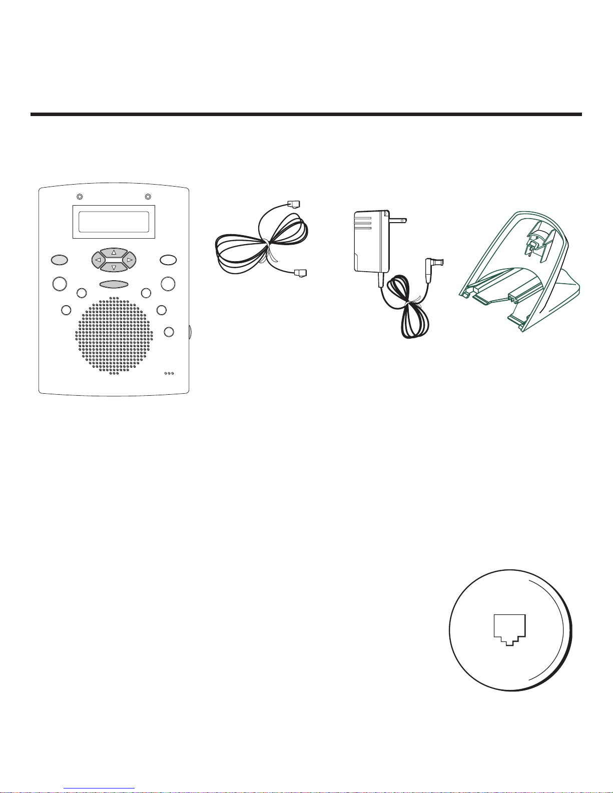
6
GETTING STARTED
Make sure your package includes the items shown here:
MODULAR JACK REQUIREMENTS
You need an RJ11C or RJ14C type modular jack, which is the most
common type of phone jack and might look like the one pictured
here. If you don’t have a modular jack, call your local phone
company to find out how to get one installed.
2-9992 unit
telephone cord
wall adapter
5-2378A
base plate
SELECT
ANSWER ON
NEW CALLS/
MESSAGES
PLAY•STOP
ERASE MSG
DELETE CID
CALLER ID
PROGRAM CID
DIAL CID
MIC
SETTING
CANCEL
SCROLL UP
SCROLL DOWN
MEMO/REC
SKIP
REVIEW
7
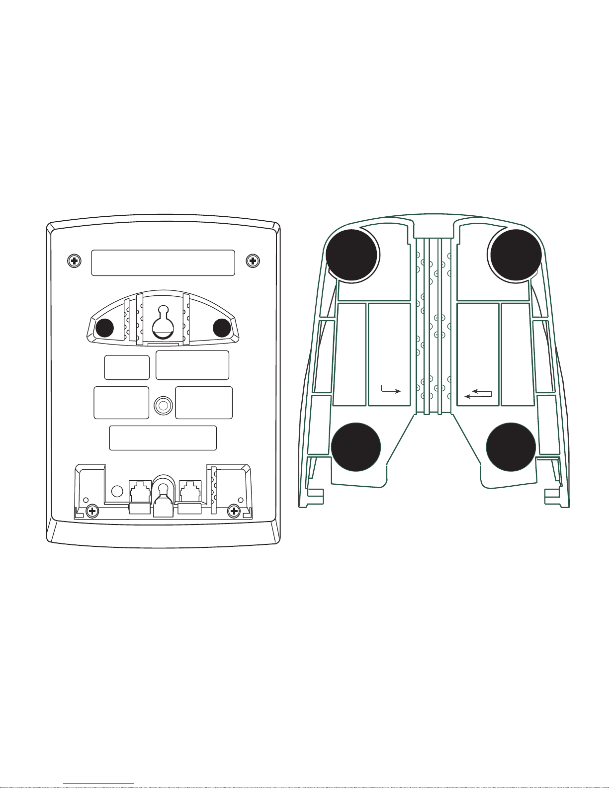
INSTALLATION OPTIONS
This unit can be used from a freestanding position on a flat surface or while mounted on the
wall. Grooves are provided on the back of the unit and desk adapter to help position the
telephone and wall adapter cords.
back of unit
desk adapter
(base plate)
TELEPHONE LINE CORDS
FIT THESE TWO SLOTS
POWER SUPPLY CORD
FITS THIS SLOT

8
DESKTOP INSTALLATION
OPTION 1
1. Feed one end each of the wall adapter
and telephone cords through the
opening on the back of the base plate.
2. Connect the wall adapter cord to the DC
9V jack.
3. Connect the cord from the telephone to
the corresponding jack.
4. Connect the cord for the wall outlet to
the corresponding jack.
5. Attach the base plate as shown below.
6. Plug the wall adapter into an AC wall
outlet.
1
2
4
5
6
3
OPTION 2
1. Connect the wall adapter and telephone
cords as described above (Steps 2-4).
2. Attach the base plate as shown above
(Figure 5).
3. Match the correct cord with its groove
and press it in.
4. Plug the wall adapter into an AC power
outlet.
Slip the base plate tabs into the
grooves provided at the bottom of
the unit. Lay the base plate flat
against the unit and push up until
you hear it click into place. To
remove the base plate, press where
it says “PUSH,” slide the base plate
down and off.
3
4

9
WALL INSTALLATION
OPTION 1
1. Connect the wall adapter to the DC 9V
cord.
Giving the cord a little slack, loop it over
the telephone jacks and press it into the
“POWER LINE” groove provided on the
right.
2. Connect the cord from the telephone to
the corresponding jack.
3. Connect the cord for the wall outlet to
the corresponding jack.
4. Slip the mounting holes over the wall
plate posts (not included) and slide the
unit firmly down into place.
5. Plug the wall adapter into an AC power
outlet.
OPTION 2
1. Connect the wall adapter to the DC 9V
cord.
2. Connect the cord from the telephone to
the corresponding jack.
3. Connect the cord for the wall outlet to
the corresponding jack.
4. Feed the cords through their corresponding grooves at the top of the unit.
5. Slip the mounting holes over the wall
plate posts (not included) and slide the
unit firmly down into place.
6. Plug the wall adapter into an AC power
outlet.
3
4
2
1
1
2
3
5
4
6
5
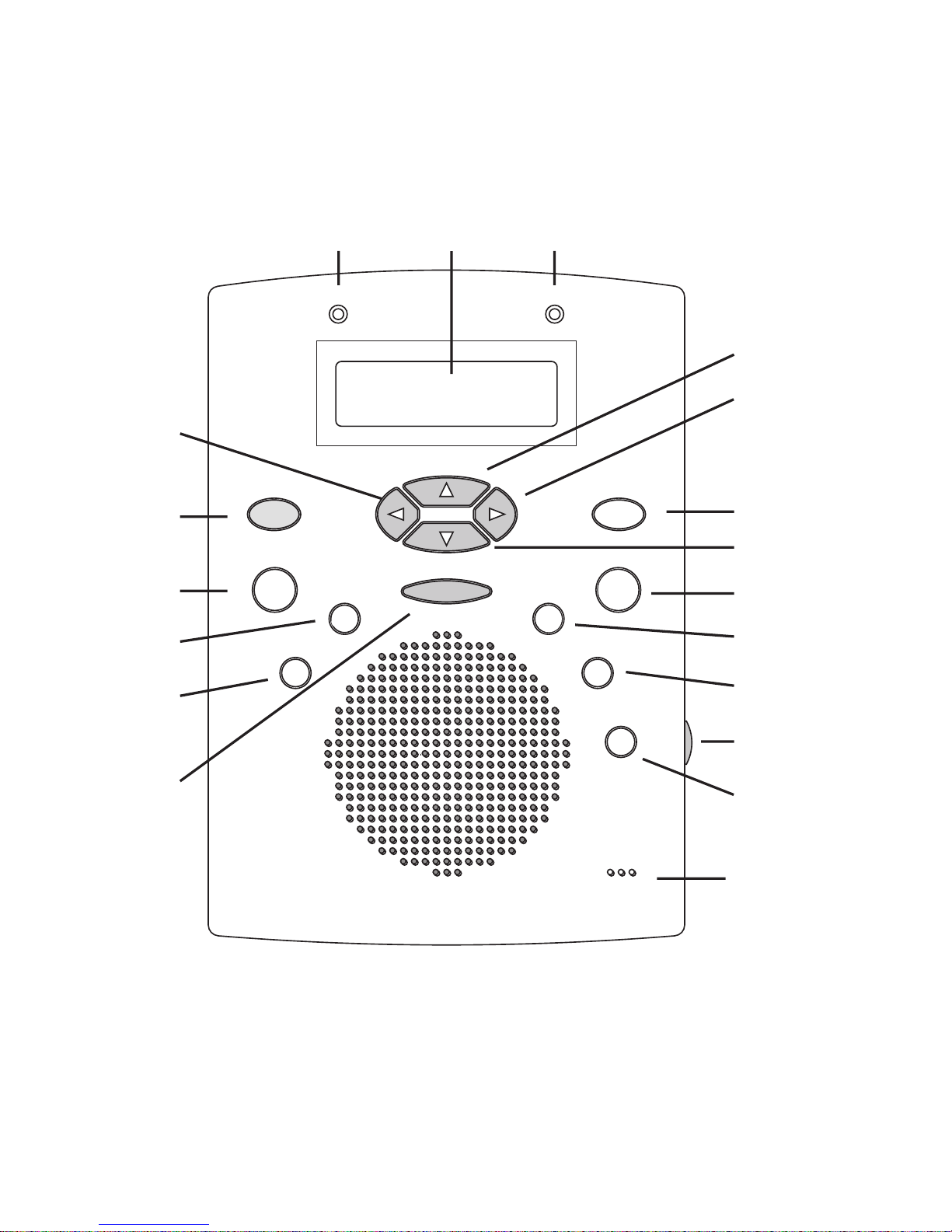
10
ANSWER ON
CANCEL
DELETE CID
DIAL CID
CALLER ID
ERASE MSG
MEMO/REC
NEW CALLS/MESSAGES
PLAY/STOP
PROGRAM CID
REVIEW
SCROLL DOWN
SCROLL UP
SELECT
SETTINGS
SKIP
VOLUME
MIC
LCD
SELECT
ANSWER ON
NEW CALLS/
MESSAGES
PLAY•STOP
ERASE MSG
DELETE CID
CALLER ID
PROGRAM CID
DIAL CID
MIC
SETTING
CANCEL
SCROLL UP
SCROLL DOWN
MEMO/REC
SKIP
REVIEW
 Loading...