

Page 1

2-9925/2-9926
900MHz Two-Line Cordless
Telephone with Headset
User’s Guide
We bring good things to life.
Page 2

FCC REGISTRATION INFORMATION
Your GE telephone equipment is registered with the Federal Communications Commission and is in compliance with
parts 15 and 68, FCC Rules and Regulations.
1 Notification to the Local Telephone Company
On the bottom of this equipment is a label indicating, among other information, the FCC Registration number and
Ringer Equivalence Number (REN) for the equipment. You must, upon request, provide this information to your
telephone company.
The REN is useful in determining the number of devices you may connect to your telephone line and still have all
of these devices ring when your telephone number is called. In most (but not all) areas, the sum of the RENs of all
devices connected to one line should not exceed 5. To be certain of the number of devices you may connect to your
line as determined by the REN, you should contact your local telephone company.
Notes
• This equipment may not be used on coin service provided by the telephone company.
• Party lines are subject to state tariffs, and therefore, you may not be able to use your own telephone equipment if
you are on a party line. Check with your local telephone company.
• Notice must be given to the telephone company upon permanent disconnection of your telephone from your
line.
2 Rights of the Telephone Company
Should your equipment cause trouble on your line which may harm the telephone network, the telephone
company shall, where practicable, notify you that temporary discontinuance of service may be required. Where
prior notice is not practicable and the circumstances warrant such action, the telephone company may temporarily
discontinue service immediately. In case of such temporary discontinuance, the telephone company must: (1)
promptly notify you of such temporary discontinuance; (2) afford you the opportunity to correct the situation; and
(3) inform you of your right to bring a complaint to the Commission pursuant to procedures set forth in Subpart E
of Part 68, FCC Rules and Regulations.
The telephone company may make changes in its communications facilities, equipment, operations of procedures
where such action is required in the operation of its business and not inconsistent with FCC Rules and Regulations.
If these changes are expected to affect the use or performance of your telephone equipment, the telephone
company must give you adequate notice, in writing, to allow you to maintain uninterrupted service.
INTERFERENCE INFORMATION
This device complies with Part 15 of the FCC Rules. Operation is subject to the following two conditions: (1) This
device may not cause harmful interference; and (2) This device must accept any interference received, including
interference that may cause undesired operation.
This equipment has been tested and found to comply with the limits for a Class B digital device, pursuant to Part 15 of
the FCC Rules. These limits are designed to provide reasonable protection against harmful interference in a residential
installation.
This equipment generates, uses, and can radiate radio frequency energy and, if not installed and used in accordance
with the instructions, may cause harmful interference to radio communications. However, there is no guarantee that
interference will not occur in a particular installation.
If this equipment does cause harmful interference to radio or television reception, which can be determined by
turning the equipment off and on, the user is encouraged to try to correct the interference by one or more of the
following measures:
• Reorient or relocate the receiving antenna (that is, the antenna for radio or television that is “receiving” the
interference).
• Reorient or relocate and increase the separation between the telecommunications equipment and receiving
antenna.
• Connect the telecommunications equipment into an outlet on a circuit different from that to which the receiving
antenna is connected.
• Consult the dealer or an experienced radio/TV technician for help.
If these measures do not eliminate the interference, please consult your dealer or an experienced radio/television
technician for additional suggestions. Also, the Federal Communications Commission has prepared a helpful
booklet, “How To Identify and Resolve Radio/TV Interference Problems.” This booklet is available from the U.S.
Government Printing Office, Washington, D.C. 20402. Please specify stock number 004-000-00345-4 when
ordering copies.
HEARING AID COMPATIBILITY
This telephone system meets FCC standards for Hearing Aid Compatiblility.
2
FCC NUMBER IS LOCATED ON THE CABINET BOTTOM
REN NUMBER IS LOCATED ON THE CABINET BOTTOM
Page 3

INTRODUCTION
O
H
A
G
O
T
S
T
Your GE 900 MHz Cordless Telephone is designed to give you flexibility in
use and high quality performance. To get the most from your new
cordless telephone, we suggest that you take a few minutes right now to
read through this instruction manual.
TABLE OF CONTENTS
FCC REGISTRATION INFORMATION .... 2
INTERFERENCE INFORMATION ............ 2
EARING AID COMPATIBILITY ........... 2
H
NTRODUCTION ..................................... 3
I
BEFORE Y OU BEGIN ........................... 4
ODULAR JACK REQUIREMENTS ...... 4
M
ETTING STARTED ................................ 4
G
INSTALLATION OPTIONS ...................... 5
ESKTOP INSTALLATION ...................... 6
D
ALL MOUNT INSTALLATION .............. 8
W
CORDLESS PHONE BASICS .................... 10
AKING A CALL ............................. 10
M
INE INDICATOR LIGHTS ................ 10
L
DUAL RINGER T ONES ....................11
EDIAL(RE/PA) ...........................11
R
ECEIVING A CALL ............................11
R
FLASH BUTTON................................11
OL (VOLUME) SWITCH ................... 12
V
RING/PWR (
RINGER AND POWER)
SWITCH .................................. 12
UTE BUTTON ............................... 13
M
EMPORARY T ONE ........................... 13
T
HOLD BUTTON ............................... 14
ONFERENCE BUTTON...................... 14
C
AGING THE HANDSET ...................... 14
P
A
DVANCED FEATURES .......................... 15
CHANNEL BUTTON (CHAN)............. 15
HEMEMORY FEATURE .................... 15
T
TORING A NUMBER IN MEMORY ... 15
S
CHANGING A STORED NUMBER ...... 16
TORING A REDIAL NUMBER ........... 16
S
TORING A PAUSE IN MEMORY ...... 16
S
DIALING A STORED NUMBER ......... 17
HAIN DIALING FROM MEMORY ..... 17
C
EADSET AND BELT CLIP OPERATION ..... 18
H
CONNECTING A HEADSET TO HANDSET .18
ONNECTING THE BELT CLIP .............. 18
C
HANGING THEBATTERY ....................... 19
C
BATTERY SAFETY PRECAUTIONS ..... 19
ROUBLESHOOTING GUIDE ................... 20
T
ROUBLESHOOTING GUIDE (CONTINUED).21
T
GENERALPRODUCT CARE ..................... 22
AUSES OFPOOR RECEPTION ................ 22
C
ERVICE ............................................ 23
S
ACCESSORY ORDER FORM ................... 24
NDEX ............................................... 25
I
IMITED W ARRANTY ............................ 26
L
WARNING:
OR ELECTRICAL SHOCK HAZARD,
DO NOT EXPOSE THIS PRODUCT
TO RAIN OR MOISTURE.
TO PREVENT FIRE
CAUTION
RISK OF ELECTRIC SHOCK
THE LIGHTNING
FLASH AND ARROWHEAD WITHIN THE
TRIANGLE IS A
WARNING SIGN
ALERTING YOU OF
"DANGEROUS
VOLTAGE" INSIDE
THE PRODUCT.
DO NOT OPEN
CAUTION: TO REDUCE THE
RISK OF ELECTRIC SHOCK,
DO NOT REMOVE COVER
(OR BACK). NO USERSERVICEABLE PARTS INSIDE. REFER SERVICING
TO QUALIFIED SERVICE
PERSONNEL.
SEE MARKING ON BOTTOM / BACK OF PRODUCT
THE EXCLAMATI
POINT WITHIN T
TRIANGLE IS
WARNING SI
ALERTING YOU
IMPORTAN
INSTRUCTION
ACCOMPANYIN
THE PRODUC
3
Page 4
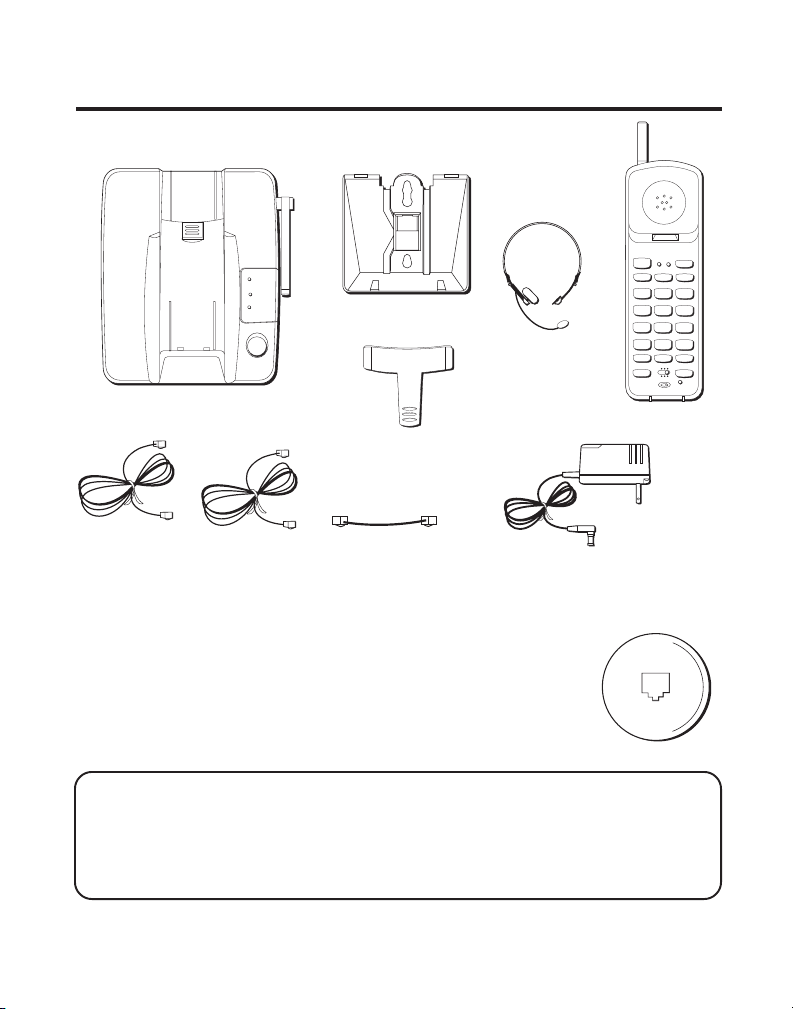
GETTING STARTED
Make sure your package includes the items shown here.
LINE 1
LINE 2
CHARGE/
PAGE
PAGE
Base
Base plate
Headset
(optional for
2-9925)
Belt clip
(optional for
2-9925)
LINE 1
LINE 2
TALK
LINE 1
LINE 2
ABC
1
2
JKL MNO
GHI
4
5
PQRS
TUV
7
8
OPER
TONE
0
*
RE/PA
MUTE
ON OFF–RING
FLASH CONF
PWR–ON OFF
Handset
WXYZ
CONF/MUTE
BAT LOW
CHAN
HOLD
DEF
3
6
9
#
MEM
Two telephone line cords
Short telephone line cord
AC power adapter
BEFORE YOU BEGIN
MODULAR JACK REQUIREMENTS
You need an RJ11 type modular jack, which is the most
common type of phone jack and might look like the one
pictured here. If you don’t have a modular jack, call your
local phone company to find out how to get one installed.
INSTALLATION NOTE: Some cordless telephones operate at frequencies that
may cause interference to nearby TVs and VCRs. To minimize or prevent such
interference, the base of the cordless telephone should not be placed near or on
top of a TV or VCR. If interference continues, moving the cordless telephone
farther away from the TV or VCR will often reduce or eliminate the interference.
4
Page 5
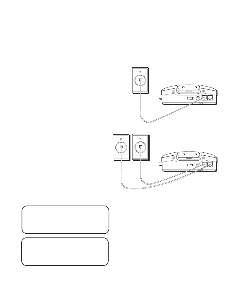
INSTALLATION OPTIONS
Although you can use your GE 2-line cordless telephone with a single
phone line, you must have two lines (separate phone numbers) to use a
two-line system. The following diagrams show two possible systems:
Two Lines on Single Modular Jack
One type of two-line phone
system uses a single RJ14
modular jack which contains both
phone lines. Connect the phone
cord to the L1 and L2 jack.
You must use a 4-conductor
telephone line cord like the ones
that are packed with your unit.
Line 2
Each Line on a Separate Modular Jack
If you have two separate phone
jacks, each with its own line,
connect one of the phone cords to
the L2 jack, and connect the
remaining phone cord to the L1
and L2 phone jack located on the
back of the phone.
Line 1
NOTE: Connect the phone cord
from the L1 and L2 jack to the
outlet that you want to be line 1.
NOTE: Two-line capability
requires two-line service from
your local telephone company.
5
Page 6
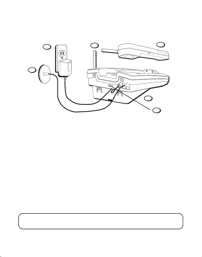
DESKTOP INSTALLATION
1
7
2
T/P switch
6
5
3
Two Lines on a Single Modular Jack
1. Make sure base plate is securely fastened.
2. Set the T/P switch to T for touch-tone service, or P for pulse (rotary)
service. If you don’t know which type of service you have, check with
the phone company.
3. Raise the base antenna.
4. Set the RING switch to ON so the handset rings for incoming calls.
5. Plug the telephone line cord into the L1 and L2 jack located on the back
of the phone and into a dual line modular jack.
6. Plug the power supply cord into the base and into an AC outlet.
7. Place handset in the base to charge for 12 hours. The CHARGE/PAGE
light comes on indicating that the battery is charging. If you don’t
charge the handset battery properly (for 12 hours) when you first
the phone, performance of the battery will be compromised.
NOTE: Use only the Thomson power supply that is compatible with this unit.
Using other adapters may damage the unit.
6
Page 7
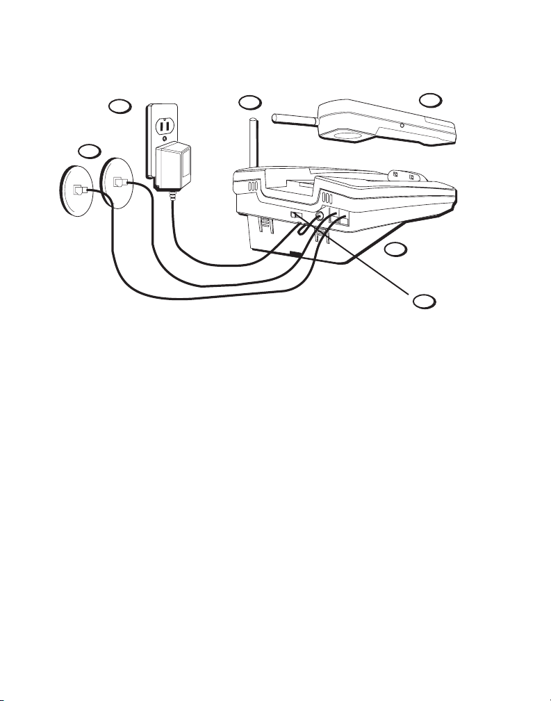
6
5
3
7
1
2
T/P switch
Each Line on a Separate Modular Jack
1. Make sure base plate is securely fastened.
2. Set the T/P switch to T for touch-tone service, or P for pulse (rotary)
service. If you don’t know which type of service you have, check with
the phone company.
3. Raise the base antenna.
4. Set the RING switch to ON so the handset rings for incoming calls.
5. Plug one of the telephone line cords into the L2 jack and into a single
line modular jack. Connect the remaining phone cord to the L1 and L2
phone jack located on the back of the phone and into a single line
modular jack.
6. Plug the power supply cord into the base and into an AC outlet.
7. Place handset in the base to charge for 12 hours. The CHARGE/PAGE
light comes on indicating that the battery is charging. If you don’t
charge the handset battery properly (for 12 hours) when you first
the phone, the battery’s long-term performance will be compromise
7
Page 8
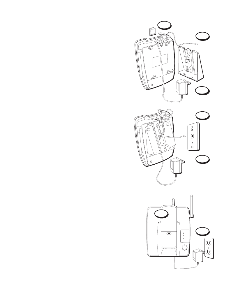
WALL MOUNT INSTALLATION
Two Lines on a Single Modular Jack
1. Remove the handset hook; turn it upside
down, and put it back in the slot. You need
to do this so the handset doesn’t fall out of
the base.
2. Plug the short telephone line cord into
the jack marked L1 and L2 on the back of
the unit and plug the other end into a
modular wall jack.
3. Connect the power supply adapter to the
POWER 9V DC jack on the back of the unit.
Then thread it through the bottom of base.
4. Reverse the direction of the base plate and
replace it by putting the tabs into the slots
on the top of the unit first and snapping
the bottom tabs into place.
5. Plug the telephone line cord into the dual
line modular jack.
6. Slip the mounting holes over the wall plate
posts and slide the unit down firmly into
place. (Wall plate not included.)
7. Set the T/P switch to T if you have touch-
tone service or to P (pulse) if you have
rotary dial service.
8. Set the RING switch to ON so the handset
rings for incoming calls.
9. Plug the power supply adapter into an
AC outlet and raise the antenna.
10. Place the handset in the base to charge for
12 hours. The CHARGE/PAGE light comes
on. If you don’t charge the handset battery
properly (for 12 hours) when you first set
up the phone, the battery’s long-term
performance will be compromised.
10
1
2
3
4
5
9
LINE 1
LINE 2
CHANRGE/
PAGE
PAGE
8
Page 9

Each Line on a Separate Modular Jack
1. Remove the handset hook; turn it upside
down, and put it back in the slot. You need
to do this so the handset doesn’t fall out of
the base.
2. Plug the short telephone line cord into the
jack marked L1 and L2 on the back of the
unit and plug the other end into a
modular wall jack.
3. Plug the remaining telephone line cord into
the L2 jack on the back of the unit.
4. Connect the power supply adapter to the
POWER 9V DC jack on the back of the unit,
and then thread it through the bottom of base.
5. Reverse the direction of the base plate and
replace it by putting the tabs into the slots on
the top of the unit first, and then by snapping
the bottom tabs into place.
6. Plug the telephone line cord from the L1 and
L2 jack into a single line modular jack that you
want to be line 1.
7. Plug the other telephone line cord into the
single line modular jack you want to be line 2.
8. Slip the mounting holes over the wall plate
posts and slide the unit down firmly into
place. (Wall plate not included.)
9. Set the T/P switch to T if you have touch-tone
service or to P (pulse) if you have rotary dial
service.
10. Set the RING switch to ON so the handset
rings for incoming calls.
11. Plug the power supply adapter into an AC
outlet and raise the antenna.
12. Place the handset in the base to charge for 12
hours. The CHARGE/PAGE light comes on. If
you don’t charge the handset battery properly
(for 12 hours) when you first set up the
phone, the battery’s long-term performance
will be compromised.
1
2
4
5
6
7
9
12
LINE 1
LINE 2
CHANRGE/
PAGE
PAGE
11
9
Page 10
TUV
1
4
5
6
GHI
7
PQRS
8
9
WXYZ
OPER
0
#
*
2
3
TONE
JKL MNO
ABC
DEF
LINE 1
LINE 2
HOLD
TALK
CHAN
FLASH CONF
ON OFF–RING
PWR–ON OFF
LINE 1
LINE 2
RE/PA
MUTE
MEM
CONF/MUTE
BAT LOW
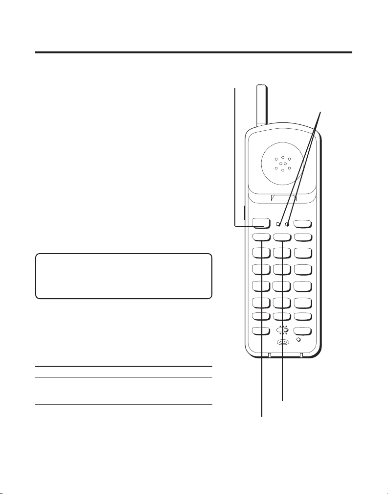
CORDLESS PHONE BASICS
MAKING A CALL
After initial set up, put handset in the
base for 12 hours to charge the battery.
The cordless phone automatically selects
the last line you used. The only two
things you need to know to make a call
are:
1. Press LINE 1 or LINE 2 to select a line
before you dial.
2. Press LINE 1 or LINE 2 (whichever line
you are talking on) or place the
handset in the base to hang up.
Otherwise, it works just like any other
phone.
NOTE: You can press TALK instead of
pressing LINE 1 or LINE 2. The phone
defaults to the last line from which you
dialed.
LINE INDICATOR LIGHTS
Above each line button is a Red indicator
light which informs you the status of
each line.
Light Status
Solid Line is in use
Blinking Line on hold
10
TALK button
LINE 1 and LINE 2
indicator lights
LINE 2 button
LINE 1 button
Page 11
DUAL RINGER TONES
TUV
1
4
5
6
GHI
7
PQRS
8
9
WXYZ
OPER
0
#
*
2
3
TONE
JKL MNO
ABC
DEF
LINE 1
LINE 2
HOLD
TALK
CHAN
FLASH CONF
ON OFF–RING
PWR–ON OFF
LINE 1
LINE 2
RE/PA
MUTE
MEM
CONF/MUTE
BAT LOW
Your cordless telephone has separate and
distinct ringer sounds for LINE 1 and LINE
2. This will allow you to determine the line
of an incoming call, even in another room.
If you are talking on one line and someone calls on the other line, the phone
alerts you by sending a signal to the
handset’s earpiece.
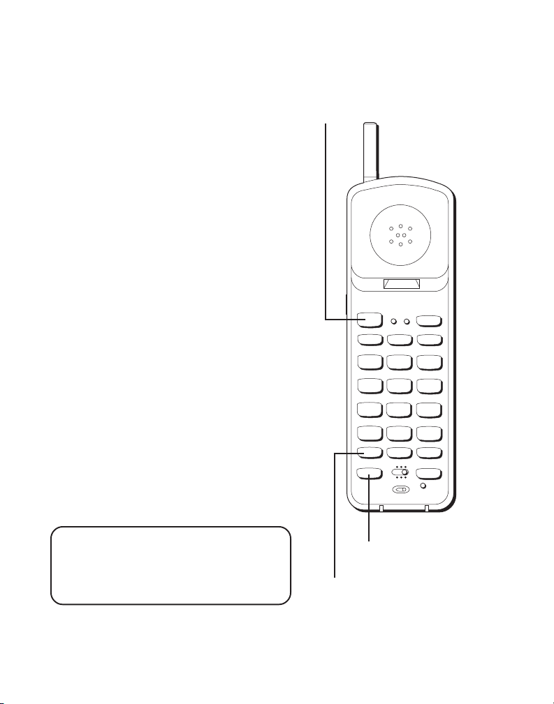
REDIAL(RE/PA)
Press the TALK button, then press the RE/
PA (redial/pause) button to redial the last
number you called (up to 32 digits).
RECEIVING A CALL
To answer a call when the handset is out
of the base, you must press TALK or the
LINE 1 or LINE 2 button.
FLASH BUTTON
Use the FLASH button to activate custom
calling services such as call waiting or call
transfer, which are available through your
local phone company.
TIP: If you press the TALK button to
activate custom calling services such as
call waiting, you’ll hang up the phone.
Press FLASH instead.
TALK button
FLASH button
RE/PA
(redial/pause)
button
11
Page 12

TUV
1
4
5
6
GHI
7
PQRS
8
9
WXYZ
OPER
0
#
*
2
3
TONE
JKL MNO
ABC
DEF
LINE 1
LINE 2
HOLD
TALK
CHAN
FLASH CONF
ON OFF–RING
PWR–ON OFF
LINE 1
LINE 2
RE/PA
MUTE
MEM
CONF/MUTE
BAT LOW
VOL (VOLUME) SWITCH
Controls the volume of the handset's
earpiece.
RING/PWR ( RINGER AND POWER) SWITCH
This is a 3-position switch that controls
the ringer and handset power.
When you move the switch to the left, the
power is on and the ringer is on.
When you move the switch to the middle
position, the power is on, but the ringer is
off.
When you move the switch to the far
right, the power is off and the ringer is off
which saves battery power. You must turn
PWR to ON (by sliding the switch to the
middle or left position) in order to make
calls or receive calls.
VOL switch (on the side
of the handset)
12
RING/PWR switch
CONF/MUTE/BAT
LOW indicator light
Page 13

MUTE BUTTON
TUV
1
4
5
6
GHI
7
PQRS
8
9
WXYZ
OPER
0
#
*
2
3
TONE
JKL MNO
ABC
DEF
LINE 1
LINE 2
HOLD
TALK
CHAN
FLASH CONF
ON OFF–RING
PWR–ON OFF
LINE 1
LINE 2
RE/PA
MUTE
MEM
CONF/MUTE
BAT LOW
Use the MUTE button to interrupt a
phone conversation to talk privately with
someone else in the room.
1. Press MUTE to activate mute feature.
2. Press MUTE again to turn it off.
TEMPORARY TONE
This feature enables pulse (rotary)
service phone users to access touch-tone
services offered by banks, credit card
companies, etc., by pressing the TONE
button to temporarily make the phone
touch-tone compatible. To get
information about your bank account, for
example, you would:
1. Press the TALK button.
2. Call the bank’s information line.
3. Press the TONE button after your call
is answered.
4. Follow the voice instructions to
complete your transaction.
5. Hang up when finished. The phone
returns to pulse (rotary) service.
TONE button
MUTE button
CONF/MUTE/BAT
LOW indicator light
13
Page 14
HOLD BUTTON
TUV
1
4
5
6
GHI
7
PQRS
8
9
WXYZ
OPER
0
#
*
2
3
TONE
JKL MNO
ABC
DEF
LINE 1
LINE 2
HOLD
TALK
CHAN
FLASH CONF
ON OFF–RING
PWR–ON OFF
LINE 1
LINE 2
RE/PA
MUTE
MEM
CONF/MUTE
BAT LOW
You can use the HOLD button to interrupt a
phone conversation without hanging up.
1. Press HOLD to place the active line on
hold.
2. Press the LINE button for that call to
resume the conversation.
CONFERENCE BUTTON
You can use the conference call feature
when you have callers on both lines and
want to have a three-way conversation.
1. Press HOLD to place the party on hold.
2. Press the other LINE button.
3. Dial the number of the second party.
4. Press the CONF button.
5. Press LINE 1 or LINE 2 when finished to
talk privately and disconnect the other
line.
6. Press LINE 1 or LINE 2 for whichever line
you are talking on or place the handset in
the base to hang up.
PAGING THE HANDSET
Press the PAGE button on the base or to
locate a misplaced handset. When you
press the PAGE button, the handset beeps.
Press the TALK button when you locate the
handset. Remember that the ringer must be
ON in order for the handset to ring.
14
HOLD button
LINE 1
LINE 2
CHARGE/
PAGE
PAGE
CONF
button
PAGE
button
Page 15

ADVANCED FEATURES
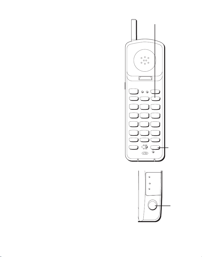
CHANNEL BUTTON (CHAN)
If you ever experience any interference or
don’t have clear voice quality, press the
CHAN button on the handset to advance
to another channel.
THE MEMORY FEATURE
Store up to 10 numbers in memory for
quick dialing.
STORING A NUMBER IN MEMORY
The phone must be off (PWR button
on, but no dial tone) when you store
numbers.
1. Press the MEM button
2. Dial the number (up to 24 digits).
3. Press MEM.
4. Press any number key (0-9) to store
the phone number in that memory
location.
CHAN button
LINE 1
TALK
PQRS
TONE
LINE 2
LINE 1
LINE 2
ABC
1
2
JKL MNO
GHI
4
5
TUV
7
8
OPER
0
*
RE/PA
MUTE
ON OFF–RING
FLASH CONF
PWR–ON OFF
CHAN
HOLD
DEF
3
6
WXYZ
9
#
MEM
CONF/MUTE
BAT LOW
MEM button
15
Page 16

CHANGING A STORED NUMBER
Use the same procedure to change a stored number as you do to store a
number— you’re just moving the phone number to a different memory
location.
S
TORING A REDIAL NUMBER
1. Press MEM.
2. Press RE/PA (redial/pause).
3. Press MEM.
4. Press any number key (0-9) to store the phone number in that memory
location.
S
TORING A PAUSE IN MEMORY
Use the RE/PA button to insert a pause when a delay is needed in the
dialing sequence (for example, when you must dial a 9 to get an outside
line or when you must enter codes to access your bank’s information line).
If you need to dial 9 to get an outside line and want to store a number in
memory without having to dial 9 each time, you would:
1. Press MEM.
2. Press 9.
3. Press RE/PA (redial/pause).
4. Dial the phone number you want to store in memory.
5. Press MEM.
6. Press any number key (0-9) to store the phone number in that memory
location.
TIP: If you need a longer pause, press RE/PA button more times.
16
Page 17

D
IALING A STORED NUMBER
1. Press the TALK button to get a dial tone.
2. Press MEM and then press the number for that memory location.
C
HAIN DIALING FROM MEMORY
Use this feature to make calls which require a sequence of numbers, for
instance if you use a calling card for a frequently called long distance
number. Basically, you dial each part of the sequence from memory. The
following example shows how you can use chain dialing to make a call
through a long distance service:
The Number For Memory Location
Long distance access number 7
Authorization code 8
Frequently called long distance number 9
1. Press the TALK button to get a dial tone.
2. Press the MEM button and then press 7.
3. When you hear the access tone, press MEM and then press 8.
4. At the next access tone, press MEM and then 9.
17
Page 18

HEADSET AND BELT CLIP OPERATION
CONNECTING A HEADSET TO
THE
HANDSET
For hands free conversation, connect the
headset (optional for 2-9925) to the
HEADSET jack as shown. The handset
receiver and microphone are disabled
when the headset is connected.
Adjust the headset to rest comfortably on
top of your head and over your ear. Move
the microphone to approximately 2 to 3
inches from your mouth.
• Press the TALK button or LINE 1 or 2 to
answer or place a call before using the
headset.
CONNECTING THE BELT CLIP
There are two slots, one on each side of
the handset.
• Attach the belt clip (optional for 2-
9925) by inserting the sides of the belt
clip into the slots. Snap the ends of the
belt clip into place.
Headset plug (2.5mm)
Slot for
belt clip
Headset
jack
HEADSET
Slot for
belt clip
18
Page 19

CHANGING THE BATTERY
Make sure RING/POWER switch is OFF
before you replace battery.
1. Remove the battery compartment door.
2. Disconnect the cord attached to the
battery pack and remove the battery
pack from the handset.
3. Insert the new battery pack and connect
the cord into the jack inside the handset.
4. Put the battery compartment door back
on.
5. If you don’t charge the handset
battery properly (for 12 hours)
when you first set up the phone
and/or when you install a new
battery pack, the battery’s longterm performance will be compromised.
BATTERY SAFETY PRECAUTIONS
• Don’t disassemble, mutilate, puncture, wet, or dispose of battery in fire.
Like other batteries of this type, if it is burned or punctured, it could
release toxic materials which can cause injury.
• Keep batteries out of the reach of children.
RBRC
Ni-Cd
RBRC
NOTE: The RBRC seal on the battery used in your Thomson
Consumer Electronics product indicates that we are participating in
a program to collect and recycle Nickel Cadmium batteries
throughout the United States of America. Please call 1-800-8BATTERY for information or contact your local recycling center.
19
Page 20

TROUBLESHOOTING GUIDE
In case of difficulty, please check the following Troubleshooting Guide
before seeking service.
Problem Solution
No dial tone • Check installation:
— Is the base power cord connected to a working outlet?
— Is TALK light on?
— Is the telephone line cord connected to the base unit and
the wall jack?
— Is a headset connected to the handset? The handset
receiver and microphone are temporarily disabled when
you connect the headset
• Disconnect the base from the wall jack and connect another
phone to the same jack. If there is no dial tone in the second
phone, the problem might be your wiring or local service.
• Is the handset out of the base unit’s range?Move closer to the
base unit.
• Make sure the battery is properly charged (12 hours).
• Is the battery pack installed correctly?
• If the phone still does not work, disconnect the power cord
and remove the battery pack. Then reconnect the power cord
and reinstall the battery pack. Place handset in the base for
10 seconds to allow it to reinitialize.
• Make sure RING/PWR switch on the handset is turned on.
Make sure the base plate is attached properly.
•
Dial tone is OK, but • Make sure the T/P switch on the base is set
can’t dial out correctly.
Handset does not ring • Make sure the RING/PWR switch on the handset is turned to
Cannot hear phone • Set the volume control on side of handset to HI.
conversation
You experience static, • Change channels.
noise, or fading in • Is handset out of range? Move closer to the base.
and out • Does the base need to be relocated?
ON (the far left position).
• You may have too many extension phones on your line. Try
unplugging some phones.
• See solutions for “No dial tone.”
• Charge handset battery.
• Make sure base is not plugged into an outlet with another
household appliance.
20
Page 21

TROUBLESHOOTING GUIDE (CONTINUED)
Problem Solution
Cannot hear the • Set the RING/PWR switch on the handset to ON (the far left
Page alert tone
Range is shorter • Press the CHAN button during the conversation to select a
than normal new channel.
Battery will not hold a • Be sure you are sufficiently charging the battery. When the
charge OR is fully charged battery has been charged for 12 hours, you can expect
and the BAT LOW lights approximately 4 hours of talk time.
position).
• Position the base antenna upward.
• Check to be sure battery contacts on both the handset and
the base are making contact and are clean; free of dirt or lint.
• When the handset is placed in the base, check that the base
CHARGE light is on.
BAT LOW light stays on • Place handset in base for 10 seconds to reset the
Memory Dialing
doesn’t work
Unit locks up • If the unit doesn’t work, reset the unit by disconnecting and
While using the headset, • Make sure the headset is plugged into the handset. When
you can’t hear the caller you plug in the headset, the handset receiver and microand the caller can’t hear you. phone are disabled.
No link between base • ID code between handset and base could be lost. Follow
and handset
that doesn’t work, charge battery for 12 hours.
• Did you program the memory location keys correctly?
• Did you follow proper dialing sequence?
• Make sure T/P switch is correctly set.
reconnecting the handset battery and then return the handset
to the base.
• If a power outage occurs while the handset is away from the
base, the handset must be returned to the base when the
power returns.
• Unplug the headset if you want to
use the handset instead.
these instructions: Make sure power switch on the handset
is OFF. Turn the power switch ON while holding down digit
2 and 8 simultaneously. Put the handset down on the base.
Press “PAGE” button until beep sound comes out. Beep
sound indicates that ID code is correctly restored.
phone. If
21
Page 22

GENERAL PRODUCT CARE
To keep your telephone working and looking good, follow
these guidelines:
• Avoid putting the phone near heating appliances and devices that
generate electrical noise (for example, motors or fluorescent lamps).
• DO NOT expose to direct sunlight or moisture.
• Avoid dropping the handset, as well as other rough treatment to
the phone.
• Clean the phone with a soft cloth.
• Never use a strong cleaning agent or abrasive powder because this will
damage the finish.
• Retain the original packaging in case you need to ship the phone at a
later date.
• Periodically clean the charge contacts on the handset and base with a
eraser.
CAUSES OF POOR RECEPTION
• Aluminum siding.
• Foil backing on insulation.
• Heating ducts and other metal construction can shield radio signals.
• You’re too close to appliances such as microwaves, stoves,
computers, etc.
• Atmospheric conditions, such as strong storms.
• Base is installed in the basement or lower floor of the house.
• Base is plugged into an AC outlet with other electronic devices.
• Baby monitor is using the same frequency.
• Handset battery is low.
• You’re out of range of the base.
22
Page 23

S
ERVICE
The FCC requires this product to be serviced only by the manufacturer or
its authorized service agents. In accordance with FCC requirements,
changes or modifications not expressly approved by Thomson Consumer
Electronics could void the user’s authority to operate this product. For
instructions on how to obtain service, refer to the warranty included in this
Guide.
Attach your sales receipt to the booklet for future reference or jot down the
date this product was purchased or received as a gift. This information will
be valuable if service should be required during the warranty period.
Purchase date _____________ Name of store _______________________
23
Page 24

✂
TOTAL
QUANTITY
PRICE*
CATALOG NUMBER
FORM
$5.61
$21.35
$18.35
5-2358
5-2420A or B
$36.35
5-2425
5-2426
$18.35
We are required by law to collect the appropriate sales tax for
each individual state, county, and locality to which the
merchandise is being sent.
Use VISA or MasterCard preferably. Money order or check must be in U.S.
*Prices are subject to change without notice.
Total Merchandise.........................................$_______________
5-4081
currency only. No COD or Cash. All accessories are subject to availability. Where
Sales Tax........................................................$_______________
.
$5.00
applicable, we will ship a superseding model.
Shipping, Handling, and Insurance............. $_______________
Total Amount Enclosed.................................$_______________
Mail order form and money order or check (in U.S. currency)
made payable to Thomson Consumer Electronics, Inc. to:
Consumer Electronics, Mail Order Department
P.O. Box 8419
Ronks, PA 17573-8419
This is your return label. Please print clearly.
To :
Name________________________________________________________
Address_____________________________________ Apt.____________
.
MasterCard
City ________________________State________ ZIP_________________
Please make sure that this form has been filled out completely.
CUSTOMER: CUT ALONG DOTTED LINE.
ORDER
DESCRIPTION
ACCESSORY
24
Headset
Belt clip
Replacement handset battery
AC power supply adapter (white)
AC power supply adapter (black)
For credit card purchases
Your complete charge card number, its expiration date and your
signature are necessary to process all charge card orders
Copy your complete account number from your VISA card.
My card expires:
Copy your complete account number from your
Copy the number above your name on the MasterCard
My card expires:
____________________________________________________________________
Authorized Signature
Page 25

INDEX
A
Accessory Order Form 24
B
Battery
Installation 19
Battery Safety 19
Belt Clip 18
Buttons
CHANNEL 15
FLASH 11
MEMORY 13, 14, 15, 16, 17
PAGE/FIND 14
REDIAL 11
TONE 13
C
Chain Dialing 17
CHANNEL Button 15
CHARGE/IN USE light 6, 7, 8, 9
Cleaning the Phone 22
Connecting a Headset to the Handset 18
Connecting the Belt Clip 18
F
FLASH button 11
H
Headset 18
I
Installation 5
Installation, desktop 5
Installation Options 5
M
Making a Call 10
MEMORY button 13, 14, 15, 16, 17
Memory Feature 15
Memory Location 15
O
Order Form 24
P
PAGE/FIND button 14
Paging the Handset 13
Poor Reception 22
Product Care 22
R
Receiving a Call 11
REDIAL 11
Ringer Switch 14
RJ14 modular jack 5
S
Service 23
Storing a Number in Memory 15
Storing a Redial Number 16
Storing a Tone Number with Pulse
Dialing in Memory 16
T
Temporary Tone 13
TONE button 13
TONE/PULSE switch 8, 9
Troubleshooting Guide 20, 21
V
Volume Button (VOL) 12
25
Page 26

LIMITED WARRANTY
What your warranty covers:
• Any defect in materials or workmanship.
For how long after your purchase:
• One year.
(The warranty period for rental units begins with the first rental or 45 days from date of shipment to the
rental firm, whichever comes first.)
What we will do:
• Provide you with a new or, at our option, a refurbished unit.
• The exchange unit is under warranty for the remainder of the original product’s warranty period.
How to make a warranty claim:
• Properly pack your unit. Include any cables, etc., which were originally provided with the product. We
recommend using the original carton and packing materials.
• Include in the package evidence of purchase date such as the bill of sale. Also print your name and address
and a description of the defect. Send standard UPS or its equivalent to:
Thomson Consumer Electronics, Inc.
Product Exchange Center
32B Spur Drive
El Paso, Texas 79906
• Pay any charges billed to you by the Exchange Center for service not covered by the warranty.
• Insure your shipment in case of loss or damage. Thomson accepts no liability in case of damage or loss.
• A new or refurbished unit will be shipped to you prepaid freight.
What your warranty
• Customer instruction. (Your Owner’s Manual provides information regarding operating instructions and
user controls. For additional information, ask your dealer.)
• Installation and set-up service adjustments.
• Batteries.
• Damage from misuse or neglect.
• Products which have been modified or incorporated into other products.
• Products purchased or serviced outside the USA.
• Acts of God, such as but not limited to lightning damage.
Product Registration:
• Please complete and mail the Product Registration Card packed with your unit. It will make it easier to
contact you should it ever be necessary. The return of the card is not required for warranty coverage.
How state law relates to this warranty:
• This warranty gives you specific legal rights, and you may have other rights which vary from state to state.
If you purchased your product outside the USA:
• This warranty does not apply. Contact your dealer for warranty information.
does not
cover:
Model 2-9925/2-9926 (Rev. 3, E/S)
15335320
98-28
Printed in Thailand
© 1998 Thomson Consumer Electronics, Inc.
P.O. BOX 1976, Indianapolis, IN 46206
Trademark(s) ® Registered
Marca(s) Registrada(s)
 Loading...