

Page 1
.. . . .
—-
—
——
——
——
. . ,.
.
.:
..”
–~~
. . .
. .
Page 2

TABLE OF CONTENTS
SECTION
IN PRODUCTION . . . . . . . . . . . . . . . . . . . . . . . ...3
A. Parts Checklist . . . . . . . . . . . . . . . . . . . ...3
CONTROLS and FEATURES . . . . . . . . . . . . . ...4
A. Telephone Controls . . . . . . . . . . . . . . . ...5
8. Telephone Features . . . . . . . . . . . . . . . ...5
INSTALLATION . . . . . . . . . . . . . . . . . . . . . . . . ...6
A. introduction...-.....,.. . . . . . . . . . ...6
E. installation . . . . . . . . . . . . . . . . . . . ...6-7
TELEPHONE OPERATION
A. Introduction . . . . . . . . . . . . . . . . . . . . . ...8
8. How to Make and Receive Calls . ...-..8
C. Automatic Radial . . . . . . . . . . . - -.......8
TELEPHONE MEMORY
. .
,,
.’
.,
. . . .
..-
----- :
.:.. TELEPHONE SERVICE . . . . . . . . . . . . . . . . . ...14
...
.. .. .
. . -. ..:
-- ... .
. .-:,:..
... . .
. . ...
. .
. .-:
..:,
:.
OPERATION . . . . . . . . . . . . . . . . . . . . . . . . . . . ...9
A, Introduction . . . . . . . . . . . . . . . . . . . . . ...9
8. How to Store . . . . . . . . . . . . . . . . . . . . ...9
C. ~owto Dial aStored~umber . . . . . ...10
0. How to Chain Dial Using Memory . . ...10
E. Storing aPause in Dialing . . . . . . . . ...11
F. PAEXand P8X use . . . . . . . . . . . . . . ...11
G. Changing or Correctinga
Stored ~umber . . . . . . . . . . . . . . . . . . ...11
PRUDUCT CARE . . . . . . . . . . . . . . . . . . .-.....12
A. To Xeplace 6ackup6attery . . . . . . . ...12
8. 8atte~ Safety Precautions . . . . . ... . ...12
C. General Product Care . . . . ..-~ . . . . ...13
D. Replaceable Telephone Cord . . . . . . ...13
A. Sewice Checklist . . . . . . . . . . . . . . . . ...14
PAGE
S~CTION
TWO YEAR LIMITED WARRANTY
TELEPHONE . . . . . . . . . . . . . . . . . . . . . . . . . ..I5
SERVICE INFORMATION . . . . . . . . . . . . . . . ...15
FCCREGiSTRAT!ON
INFORMATION . . . . . . . . . . . . . . . -...........16
INTERFERENCE INFORMATION . . . . . . . . . ...16
HEARING AID
COMPATIBILITY . . . . . . . . . . . . .
CLOCK RADIO CONTROLS andFEATVRES. .17
A. Clock Radio Controls
and Features . . . . . . . . . . . . . . . . . . . ...17
CLOCK RADIO OPERATION . . . . . . . . . . . . ...18
TWO YEAR LIMiTED WARRANTY
FM/AMCLOCK . . . . . . . . . . . . . . . . . . . . . . . ...22
ACCESSORY ORDER FORM . . . . . .. OUTLD-OUT
A-
Introduction . . . . . . . . . . . . . . . . . . . . ...18
A.
Power Failure Indicator . . . . . . . . . . . ...18
B.
Radio Operation . . . . . . . . . . . . . . . . . ...18
c.
Automatic Radio Muting . . . . . . . . . . ...18
D.
E.
8uilt-in AFC . . . . . . . . . . . . . . . . . . . . ...18
Antennas . . . . . . . . . . . . . . . . . . . . . . ...19
F.
Time Set . . . . . . . . . . . . . . . . . . . . . . . ...19
G.
Minutes and Seconds
H.
Time Display . . . . . . . . . . . . . . . . . . . ...19
1.
Wake Time . . . . . . . . . . . . . . . . . . . . . ...19
Wake to Radio or Alarm.... . . . . . . ...20
J.
Sleep to the Radio . . . . . . . . . . . . ...20-21
K.
Snooz-Alarm . . . . . . . . . . . . . . . . . . . . . ..2I
L.
“NoWorry” Battery Backup System . ..21
M.
-
. . . . . . . . . ...16
A’
PAGE
.. .
WARNING: TO PREVENT FIRE
OR ELECTRIC SHOCK HAZARD,
00 NOT EXPOSE THIS PRODUCT
TO RAINOR MOISTURE.
2
L~HTNtNG
THE
~ASHANDARROWHEAOWrTMNTHE
TRIANGLE&
WARNING
ALERTINGYOUOF
“DANGEROus TO QUALIFIEDSERVICE
VOLTAGETHEPROOUCT.
CAUTION:TOREOUCETHE
RIsKOFELECTRICSHOCKI
00 NOTREMOVE
A (OR BACK).
SIGN SERVICEABLEPARTSlN-
SIOE. REFERSERVICING
INSIDEPERSONNEL.
COVER
NO USER-
SEEMARKlNGON80~OM/8ACKOFPROOUCT
THEEXCLAMATION
POINTWITHINTHE
TRIANGLE IS A
WARNING
ALERTINGYOUOF
IMPORTANT
lNsTRucTloNs
ACCOMPANYING
THEPROOUCT.
SIGN
Page 3
.“
. .
INTRODUCTION
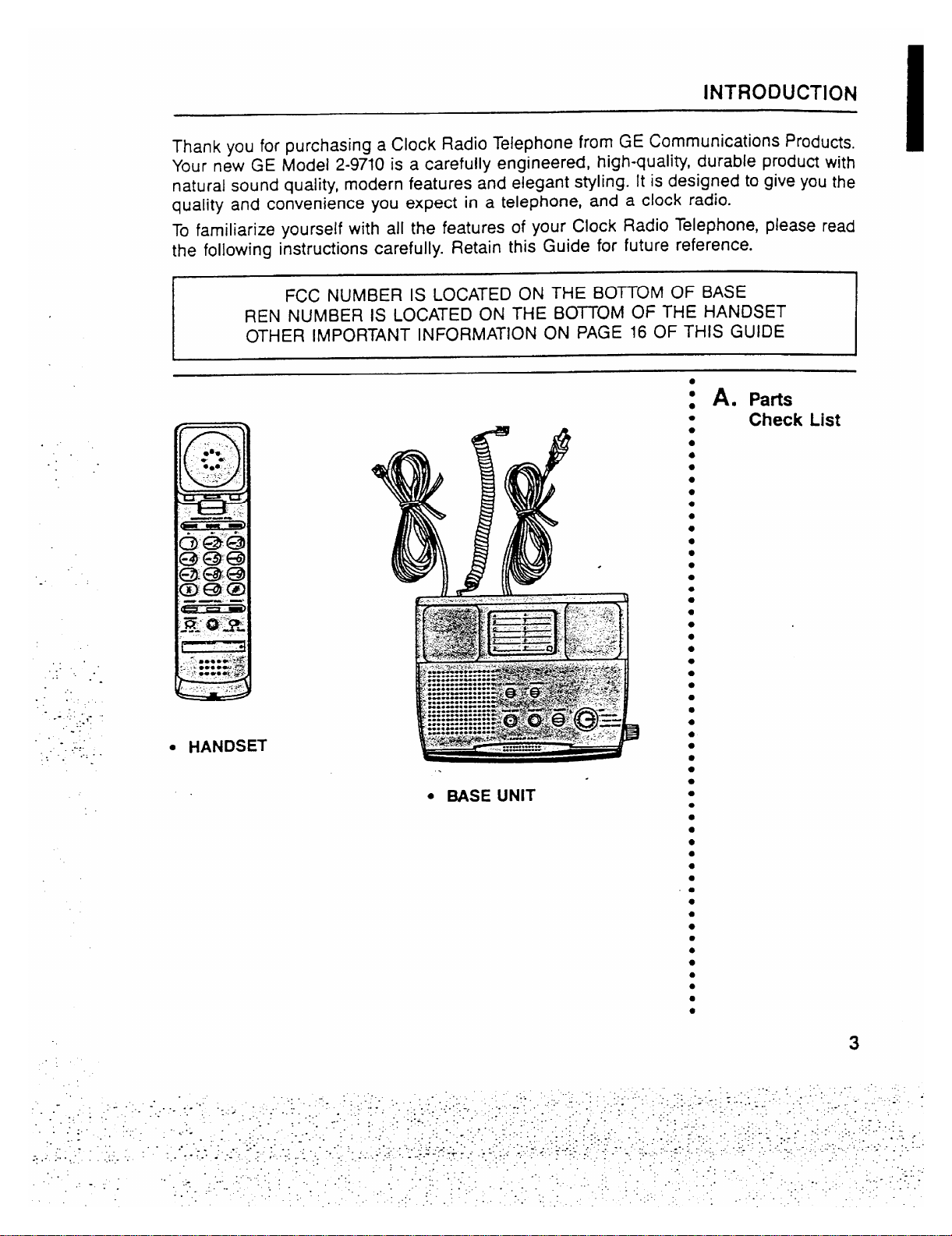
Thank YOU for purchasing a Clock Radio Telephone from GE Communications Products.
Your new GE Model 2-9710 is a carefully engineered, high-qualiW, durable produ~ with
natural sound quality, modern features and elegant styling. It is designed to give YOUthe
quality and convenience you expect in a telephone, and a clock radio.
TO familiarize yourself with all the features of your Clock Radio Telephone, please read
the following instrutiions carefully. Retain this Guide for future reference.
v
FCC NUMBER IS LOCATED ON THE BOTTOM OF BASE
REN NUMBER IS LOCATED ON THE BO~OM OF THE HANDSET
OTHER IMPORTANT INFORMATION ON PAGE 16 OF THIS GUIDE
1
: A. pafis
Check List
J
.. .
... .. .
.:. . -
...
... ,
..
.-.
--
:“..
-.
. .
-..
.... .
-. .
.1-.
... . .
● HANDSET
● MSE UNIT
3
Page 4
CONTROLS and FEATURES
n
.
.
J
m
.,..
. ..
.-.
..
.:. .
. ..
..
:.
. ..
.
...
,.:
.
c
;“
4
Page 5

CONTROLS and FEATURES
. ..
..
.:.
...
..:
..-.
✎✎
-. .,
..
. .
-’- .. .
.. .
.im-
.. .
..
-.-,
-..
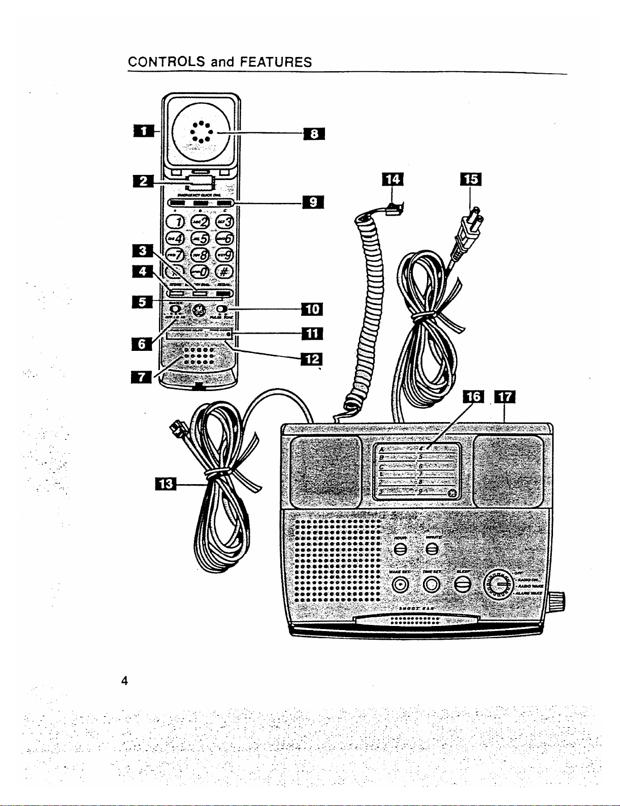
1.
Handset
2.
Handset Hook Switch
Memo~ Dial Button —
3.
Used when dialing a number
stored in memo~, locations 1-9.
4.
Store Button — Stores phone number in a MEMORY
location.
Redial Button —
5.
Redials the last number called. Also
works as PAUSE for Memory after other numbers have
been dialed.
Ringer Volume Switch
6.
— Adjusts the volume of the
ringer (Hi or Lo) or to turn ringer off.
Microphone
7.
Earpiece
8.
Quick Dial Buttons —
9.
Provide instant dialing of up to 3
important telephone numbers by pressing A, B or C.
Dialing Mode Switch — Sets the dialing mode for either
10.
Tone or Pulse (for rotary service).
Lithium Battery Cornpafiment — Located on the botiom
11.
of the telephone handset.
(Long-Life Lithium Battery Cartridge is included).
Telephone Number Display
12.
Te!ephone Line Cord
13.
Coiled Cord —
14.
AC Power Cord
15.
Memory Directo~
16.
. .
17.
Base
●
12 Number Memo~ - Includes 3 positions for “One-touch”
Connects the handset to the base unit.
quick dialing for Emergency, etc. plus 9 additional memories :
for frequefitly called numbers.
●
Switchable Pulse~one Dialing - Touch Tone or Pulse
dialing, or any combination of Tone and Pulse, for access to :
long distance services.
Long Life
Lithium BatteW - Provides Memory Back-up.
1 A. Telephone
●
●
●
●
●
●
●
●
●
●
●
●
●
●
●
●
●
●
●
●
●
●
●
●
●
●
●
●
●
●
●
●
●
●
●
●
●
●
●
●
●
●
●
●
●
●
●
-
●
:
Controls
B. Telephone
Features
●
●
●
●
●
●
●
●
●
●
●
●
●
●
5
Page 6
INSTALLATION
....
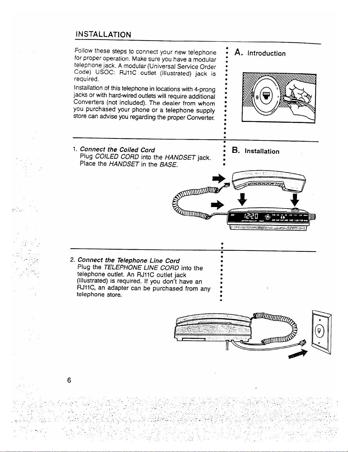
Follow these steps to connect your new telephone
for proper operation. Make sure you have a modular
telephone jack. A modular (Universal Sewice Order
Code) USOC: RJIIC outlet (illustrated) jack is
required.
Installation of this telephone in locations with 4prong
jacks or with hard-wired outlets will require additional
Converters (not included). The dealer from whom
you purchased your phone or a telephone supply
store can advise you regarding the proper Convefier.
1. Connect the Coiied
Plug COILED CORD
Place the HANDSET
..
...
. ..
Cord
the HANDSET jack. :
into
in the BASE.
A. Introduction
t
●
●
●
m
●
●
●
●
●
●
●
●
●
●
●
●
●
●
●
●
B. installation
s
●
.
—
..
..
.. .
,’. .
,.
...
-.
.. .
.:
.-l..
#-
... .
. .
. ..-:
....
2. Connect the Telephone Line Cord
Plug the TELEPHONE LINE CORD into the :
telephone outlet. An RJIIC outlet jack
●
●
●
●
(illustrated) is required. If you don’t have an :
RJ1l C, an adapter can be purchased from any :
telephone store.
●
*
6
.
Page 7
.“
. ..
..-
.. -
..:
...
. . . . .
.-. ..
-., . ..
..~,,
.
-.. .
.. .
....
...
:.
-.
. .
3. Piug in the AC Power Cord
This clock radio telephone operates on 120V :
AC household power.
Plug the AC Power Cord into the AC power
outlet.
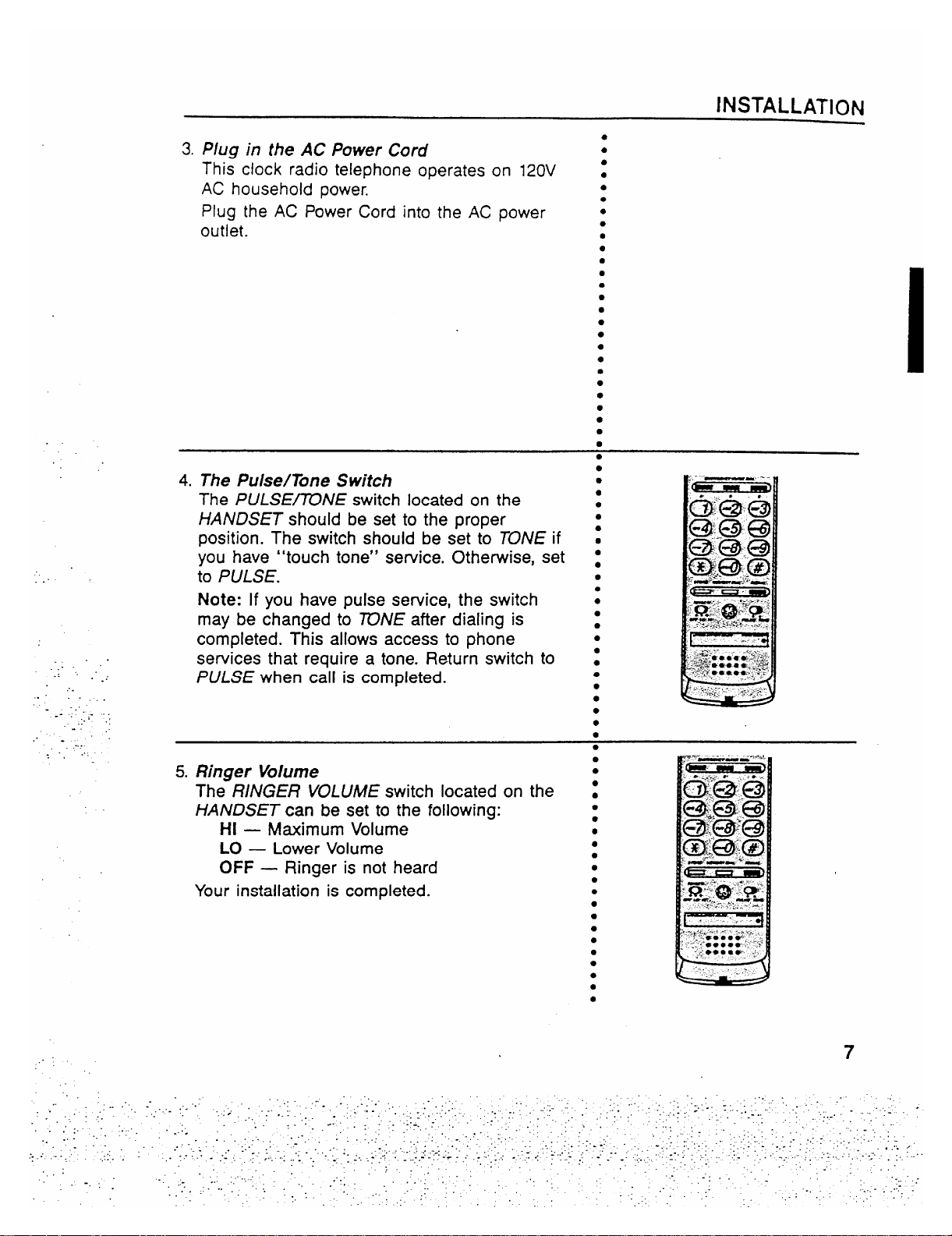
4. The Pulse/Tone Switch
The PULSE~NE switch located on the
HANDSET should be set to the proper
position. The switch should be set to TONE if
you have “touch tone” sewice. Otherwise, set
to PULSE.
Note: If you have pulse sewice, the switch
may be changed to ~NE after dialing is
completed. This allows access to phone
services that require a tone. Return switch to
PULSE when call is completed.
5. Ringer Volume
The RiNGER VOLUME switch located on the
HANDSET can be set to the following:
HI
— M=imum Volume
LO
— Lower Volume
OFF
— Ringer is not heard
Your installation is completed.
INSTALLATION
●
●
●
●
●
●
●
●
●
●
●
●
●
●
●
●
●
●
●
●
●
●
●
●
●
●
●
●
●
●
●
●
●
●
●
●
●
●
●
●
●
●
●
●
●
●
c
●
. . .
,.
7
..
Page 8

TELEPHONE OPERATION
. . .
. ..
.
.’
... .-
.:
.-. ,
-.
..
.
.....
. . ... .
The GE Model 2-9710 Clock Radio Telephone provides normal
A. introduction
:
telephone operation along with storage of up to twelve telephone s
numbers in memory for automatic dia~ing of frequently called or s
emergency numbers.
To Make A Call
1.
Pick up HANDSET.
2.
Wait for dial tone.
3.
Dial telephone number.
When finished, hang-up.
4.
To Receive a Call
1. When phone rings, pick up HANDSET and talk.
2. When finished, hang-up HANDSET.
Note: Make sure RINGER Switch is
Note:
HANDSET must be returned to BASE for radio play and
not off.
. .
alarm system operation.
The telephone automatically remembers the last number diaied :
(up to 32 digits long).
●
●
●
●
B. HOW tO
;
●
●
●
●
●
●
●
●
●
●
●
●
●
●
●
●
●
●
●
●
● “
●
●
Make and
Receive
Calls
C. Automatic
.
The number will remain in “REDIAU’ until another number is :
dialed.
To redial a number that you dialed press REDIAL,
. .
$.
●
●
●
●
●
●
●
●
●
8
●
●
●
●
●
●
●
●
●
●
●
●
●
●
●
●
●
●
●
●
●
8
Page 9

TELEPHONE MENIORY OPERATION
J
Your new GE P~lcdel 2-97?0 Clock Radio Telephone has 12
memory locations capable of storing a telephone
number of up
to 16 digits. Three telephone numbers can be stored in the 3 Quick
Dial positions and dialed with one touch. (For example: you may
want to store emergency phone numbers for quick and easy
access). 9 klemory positions are dialed with two touches
(&fE/VIORYD/AL and the number button 1-9 corresponding to’the
memory location).
Impotiant: Before you begin storing telephone numbers in
memory you must set the PULSE/TONE switch
to the correct position.
Quick Dial Numbers
1. Pick up the HANDSET
2. Push STORE.
3. Enter the telephone number (it will not actually cali
the number in this mode).
4. Push STORE again.
5. Push selected Quick Dial Location — A, 8 or C.
6. Hang up HANDSET
7. Write the name or number of party stored in memory
location on klemory Directory Card.
~
. .
..
..
.:
..
..
WHEN MAKING TEST CALLS TO EMERGENCY NUMBERS:
1. Remain on the line and briefly explain to the
dispatcher the reason for the call before hanging up.
2. Perform such activities in the off-peak hours, such as
early morning hours
Frequently Called Numbes
1. Pick up the HANDSET
2. Push STORE.
3. Enter the telephone number (it will not actually call
the number in this mode).
4. Push STORE again.
5. Push key pad 1, or 2..
6. Hang
up HANDSET
7. Write the name or number of party stored in the
memory location on htemory Directory Card.
CAUTION ~
or late evening.
., or 9 for memory location.
A. Introduction
●
●
4
●
●
●
●
●
●
●
●
●
●
●
B. HOW to
●
●
●
●
●
●
●
●
●
●
●
●
●
●
●
●
●
●
●
●
●
●
●
●
●
●
●
●
●
●
●
●
●
●
●
●
●
●
●
●
●
●
●
●
●
●
●
●
●
●
●
●
●
●
●
Store
● *e**.
● 9 **a
SOOO*
9
Page 10

TELEPHONE MEMORY OPERATION
.....
,.. ,
. ..
. . .
. .
-. .
.,
.:
-..
.,.
.. ;- -
..
-.
.....
..
Quick Dial Numbe~
1. Pick up HANDSET
2. Wait for Dial Tone.
3. Press A or B or C.
Frequently Called Numbem in Memo~
1. Pick up HANDSET
Wait for Dial Tone.
2.
3. Press MEMORY DIAL.
4. Press 1, or2. . . . or 9.
This feature allows you to dial in succession a chain of
numbers in different memo~ locations. This is useful when
you must dial more than one number in memory to complete
a call, such as with frequent calls via an independent
service (e.g. MCI or Sprint).
For example
Local Access Number of Long
Distance Company and 2 or 3
pauses atend, press . . . . . . . . . . . . . . . . . . . ...6
Authorization Code (ID), press . . . . . . . . . . . . ...7
Long distance phone number,
press . . . . . . . . . . . . . . . . . . . . . . . . . . . . . . . . ...8
To Initiate Chain Dialing
1. Press MEMORY DIAL.
2. Press 6.
3. Press MEMORY DIAL.
4. Press 7.
5. Press MEMORY DIAL.
6. Press 8.
Memoy Location
C. Howto Dial
1
●
● ✎
●
●
●
●
●
●
●
●
●
●
●
●
●
●
●
●
●
●
●
●
●
●
●
●
●
●
●
●
●
●
●
●
●
●
●
●
●
●
●
●
●
●
●
●
●
●
;
●
●
●
●
●
●
●
●
●
●
●
●
●
●
●
●
●
a Stored
Number
~
BP’
@c
Bc
I
mc
D. HOW to
Chain Dial
Using the
Memo~
[
...
10
Page 11

TELEPHONE MEMORY OPERATION
When storing a number, a momentary delay may be needed in
the dialing sequence for a stored telephone number. This is
generally used when a “PAUSE” is needed to wait for a dial tone
(e.g. after dialing a long distance access number). The REO/AL
button should be pressed at the point where a pause is needed
in the dialing sequence. During storage, pushing the REDiAL
button sewes to store a pause in the dialing sequence as often
as needed.
Note: The REDiAL key will place a pause in the dialing sequence
anytime it is pres~ afier dialing a number. When storing PAUSE
in MEMORY, each PAUSE counts as one stored digit.
●
●
E. storinga
●
●
●
●
●
●
●
●
●
●
●
●
●
●
●
●
●
●
●
●
●
9
Pause in
Dialing
-—-
. .
..-
..:
.,
..
..
.-. >
---
‘. .
. .
,. .
,.,
~:. .
,.
.. . . .
..-.:
. . .....
. .
~+
MemoW and Redial may require the use of a “PAUSE” when .
initially-dialing or storing-outside numbers. The’ sequence, then, z
: F. PABX and
PBX Use
for dialing or storing an outside number would be, for exampIe: s
9 REDIAL 12345&
Hm to Change a Stoti Numhr
Rewat the storage sequena. me nw number will repla~ the old
number at the memo~ l-ion.
HW to Clear a Stoti Nu*r
Re~at the storage sequen=. Skip step 3 in the sequenm ~.e. do
. .
not enter a telephone number). The storage Itiion will be blank
when ~uenm is mmpleted.
Hw to &M an Emr Mile Storing
Simp~ hang up and repeat the ptiure for stoting from the
beginning.
●
●
●
●
●
G. changing or
●
●
●
●
●
●
●
●
●
●
●
●
●
●
●
●
●
●
●
●
●
●
●
●
●
●
●
●
●
●
●
●
●
●
●
11
Page 12

PRODUCT CARE
A consumer replaceable long-life Lithium Battery (3V) is
installed in the phone to provide back-up power for retaining :
numbers in memory. The Lithium 8atte~ compartment is - :
located on the bottom
1. Unplug the power
telephone outlet.
of the telephone handset.
cord and unplug PHONE LINE from ●
●
●
A. ToRepiace
Backup
Batte~
●
●
●
●
●
●
●
-.
.. .
-.
. .
.. . .
.:. -
..
-., ..
. . ... .
2. Remove TELEPHONE NUMBER PLASTIC COVER and ~
CARD to expose battery holder.
●
●
Note: Insert pointed object into hole in PUSTIC COVER :
and lift. Then remove COVER and CARD.
3. Unsnap the battery door
Using a screwdriver, insert in opening at either end of
battery cafiridge, pop it up, Iifi batte~ out.
●
●
●
●
●
●
●
Dispose of battery cartridge. Replace only with GE CAT. ~~
#5-1923: When discarding batteries, be sure to dispose of .
them in the proper manner, according to your
state and
local regulations.
4. Replace battery cartridge and door
-.
..
,.’
..,.
Note: Cartridge can be inserted only one way.
5. Replace Telephone Number Card and plastic cover.
6. Plug in the power Cord and plug in the PHONE CORD. ●
Note: Numbers in memo~ must be reprogrammed.
●
●
●
●
●
●
●
●
●
●
●
a
●
●
●
●
●
●
●
●
●
●
●
●
fir your safety, please follow these simple precautions: _
●
Do not recharge, disassemble, mutilate, puncture, wet or z
dispose of Batte~ in fire. Like other batteries of this type, s
if it is burned or punctured, it could release toxic material .
which could cause injury.
Keep Battery out of reach of children.
Replace only with GE Cat. #5-1923. Accessory Order
Form included in this guide.
12
B. Batte~
✚
●
●
●
●
●
Safety
Precautions
Page 13

PRODUCT CARE
Tokeep your GE Telephone working and looking good, follow these
few simple rules:
● Avoid putting telephone near heating appliances and devices ;
J
●
●
that generate electrical noise. (i.e., motors, fluorescent lamps.) .
● Telephone should not be exposed to dir= sunlight or moisture. g
“ - Avoid dropping the Handset and other
rough treatment to the s
phone.
● Clean telephone with a soft cloth dampened with water. s
(Remember to first unplug phone from wall outlet)
● Never use a strong cleaning agent or abrasive powder, as this :
‘@@
will damage the finish.
● Retain the original packaging for future use.
The telephone line cord (from handset to telephone wall z
outlet) is one cord that can easily change its location. This
~@@
:
convenient feature allows you to change the location of the .
cord. Your decision as to the location of the line cord will z
depend on where your unit is located in reference to the :
tejephone outlet.
To remove line cord from current location
1. Remove MODULAR PLUG from telephone wall outlet and ‘CREW
HANDSET.
2. Remove SCREW from TELEPHONE CORD STRAIN
RELIEF housing located on the bottom of the CLOCK
RADIO.
3. Lift off HOUSING and unwrap CQHD from strain relief.
●
●
●
●
●
●
●
●
Tomove line cord to new location (on other side of base unit) :
1. To install, WRAP CORD around the STRAIN RELIEF as s
indicated and, replace HOUStNG and SCREW. -
2. Plug MODULAR PLUG back into telephone wall outlet
and HANDSET.
●
●
●
●
●
●
C. General
Product
Care
Q
D. Changing
Location of
Phone Cord
.. -.
The telephone cord (from handset to telephone wali outlet)
is actua!ly one cord which is easily replaced if damaged.
replace
To
1.
Remove MODULAR PLUG from telephone wall outlet and
HANDSET.
2.
Remove SCREW from TELEPHONE CORD STRAIN
RELIEF housing located on the bottom of the CLOCK
RADIO.
3.
Lift off HOUSING and unwrap cord from STRAIN
RELIEF.
To
install replacement, wrap cord around the strain relief as
indicated and, replace housing and screw.
s E. Replaceable
●
●
●
●
●
●
●
●
●
●
Telephone
CORD
13
Page 14

TELEPHONE SERVICE
If your Telephone does not work properly, follow the Sewice Checklist. If it is still
inoperative then disconnect the Telephone and t~ another telephone to determine if
the problem is with the telephone line. If it is the telephofle line, notify the telephone
company for semice.
....
. ...
..
.. .
...”
.
. .
..
:..
..,.
..:,
. .
If the Telephone continues to malfunction, please make sure
YOU have followed
all
the instructions in this manual to correct the problem.
If you continue to have problems, refer to the service information on page 15 of
this
guide and the Telephone must be disconnected.
A. Sewice Checklist
TELEPHONE
PROBLEM
1. No Dial tone
. Check Cords to make sure they are inserted correctly,
● Does HOOK SWITCH extend fully when handset is
removed from cradle?
2. Phone does not dial
● Check PULSE~NE switch. Place in the PULSE
position.
3. You cannot be
heard by other party
4. Memory Dialing
Problems
5. Incoming and
-.
..
;-
Outgoing voice
volume is too low
6. Phone does not ring
● Check that handset coil cord is fully inseded at both
ends.
● Did you program number correctly?
c Did you follow the proper dialing sequence?
● Check that other phones are off hmk at the same time. If
so, this is a normal condition as volume drops when
additional phones are used at once.
. Is RINGER SELECT set to OFF position?
● Are you using too many phones on one line? The total
REN of all phones should not be greater than the
maximum REN for your calling area. (Usually maximum
REN is 5. See FCC Registration Information on page 16.)
SOWTION
7. Tone Feedback
Flutter while dialing
in pulse mode
8. Loss of Memory
14
● This is normal as power is fluctuating with phone out-
pulsing.
. Is batte~ installed correctly?
● Does battery need to be replaced?
Page 15

.“
,..
,.-
. ..
.. .
-----
.. .
..:
.. . . . .. .
..
..
-::.
.
. .
.-?
.. . .
:.
-....
.:..
..:.
TWO YEAR
LIMITED WARRANTY TELEPHONE
What does your warranty cavefl
● Any defect in material or workmanship.
For how long after the
s Two years.
● The warranty for rental units begins with the first rental.
What will we do?
● Provide you with a new, or at our option, a reconditioned unit.
“ The exchange unit is warranted for the remainder of your product’s original two-year
How do you make a warranty claim?
● Properly pack your unit. Include any cables, etc., which were originally provided with the produ~. We
recommend using the original cation and packing materials.
● Include in the package a copy of the sales receipt or other evidence of date of original purchase. If the
unit was a gift, provide a statement specifying the date received. AISOPrint YOUrname and address and
a description of the defect.
● Ship the unit standard UPS or equivalent to:
Thomson Consumer Electronics, Inc.
Product Exchange Center
32 Spur Drive
El Paso, Texas ~906
● Pay any charges billed to you by the Exchange Center for service not covered by the warranty.
“ A new or reconditioned unit will be shipped to you prepaid freight.
What does your warranty not covefl
● Customer instruction. YourOwner’s Manual provides information regarding operating instructions and
user controls. For additional information, ask your dealer.
● Installation and set-up sewice adjustments.
● Batteries.
● Damage from misuse or neglect.
● Product which have been modified or incorporated into other products.
● Product purchased or semiced outside the USA.
How does state law relate to this warranty?
“ This warranty gives you specific legal rights, and
. .
to state.
What if you purchased your unit in Canada?
● Refer to the Canadian Warranty.
For products purchased outside the United States and Canada, see dealer for warranty.
Thomson Consumer Electronics, Inc.
original purchase?
warranty perio~.
you may also have other rights which va~ from state
SERVICE INFORMATION
FCC requires this product be serviced only by the manufacturer or its authorized sewice agents. In
accordance with FCC requirements, changes or modifications not expressly approved by Thomson
Consumer Electronics could void the user’s authority to operate this product. For instructions on how
to obtain service, refer to the warranty included in this Guide or call customer service, telephone
number: 800-~8-0329.
Attach your sales receipt to the booklet for future reference or jot down the date this product was
purchased or received as a gift. This information will be valuable if sewice should be required during
the warranty period.
Purchase date
Name of store
15
Page 16

.. .
.. ..
.
.:. .
...
.. . .
..
-- .:.
. ::, .
. . . .
. . . .-,
:.-
-.,
FCC REGISTRATION [FORMATION
Your GE telephone equipment is re istered with the Federal Cammunicatlons Commission and is in
compliance with pans 15 and 68, F C Ruies and Regulations.
1.
Notification to the
On the bottom of this eq~ipment is a label indicating among other information, the FCC Hegfstration
number and
this information to
The RE~
is useful to determine the number of devices you may connect toyOUrteiephOnelineand still
bcal Telephone Company
Ringer Equivalence Number (REN) for the equipment. YOU must, upon request, provide
your telephone company.
z
have all these devices ring when your telephone number is called. In most (but not all) areas, the sum
of the ~E~’s of all devices conneded to one line should not exceed 5. To be
ceflainof the number of
devices you may conned to your line as determined by the REN, YOUshould contad your local telephone
company.
NOTES: This equipment may not be used on coin semice
Party lines are
equipment if you are on a party line. Check with
subjed to state tariffs, and therefore, you may not be able to useyour own telephone
your local telephone company.
Notice must be given to the telephone company upon
provided by the telephone company.
permanent disconnection of your telephone from
your line.
2.
Rights of the Te/ephofle Company
Should your equipment cause trouble on your line which may harm the teiephone nemork, the telephone
company shall, where predicable, notify you that tempora~
discontinuanceofsewjcemayberequired.
Where prior notice is not practicable and the circumstances warrant such action, the telephone company
may temporarily disconttiue sewice immediately. In ase of such tempora~ discontinuance, the telephone
company must: (1)promptly notify you of such temporary d~scontinuance, (2) afford you the opportunity
to corred the situation and (3) inform you of your right to bring a complalnt to the commission
pursuant
to procedures set forth in Subpart E of Part M, FCC Rules and Regulations.
The telephone company may make changes in its communications facilities, equipment, operations of
procedures where such adion is required in the operation of its business and
notinconsistent with FCC
Rules and Regulations. If these changes are expected to affed the use or p.:fiomance of your telephone
equipment, the telephone company must give you adequate notice, in wrltlng, to allow you to maintain
uninterrupted semice.
INTERFERENCE INFORMATION
This device complies with Part 15 of the FCC Rules. Operation is subjed to the following two
conditions: (1) This device may not cause harmful interference, and (2) This device must accept any
interference received, including interference that may cause undesired operation.
This equipment has been tested and found to comply with the limits for a Class B digital device,
pursuant to Part 15 of the FCC Rules. These limits are designed to provide reasonable protection
against harmful interference in a residential installation.
1.
-.
-.
T~is equipment generates, uses and can radiate radio frequency energy and, if not installed and used
in accordance with the instructions, may cause harmful intederence to radio communications. However,
there is no guarantee that interference will not occur in a particular installation.
If this equipment does cause harmful intetierence to radio or television reception, which can be
determined by turning the equipment off and on, the user is encouraged to try tO correct the
interference by one or more of the following measures:
s Reorient or relocate the receiving antenna (that is, the antenna for radio or television that is “receiving”
the interference).
● Reorient or relocate and increase the separation between the telecommunications equipment and
receiving antenna for radio or television that is “receiving” the lnte~erence).
● Connect the telecommunications equipment into an outlet on a circuit different from that to which
the receiving antenna is connected.
● Consult the dealer or an experienced radio~ technician for help.
If these measures do not eliminate the interference, please consult your dealer or an experienced
radio/television technician for additional suggestions. Also, the Federal Communications Commission
has prepared a helpful booklet,
“HOW To Identify and Resolve Radio~ Interference Problems”. This
booklet is available from the U.S. Government Printing Office, Washington, D.C. 20402. Please specify
stock number OWOOO-003454 when ordering copies.
HEARING AID COMPATIBILITY
This telephone system meets FCC standards forHearing Aid Compatibility.
16
.
Page 17

CONTROLS and FEATURES
. ..
-1
u
A. Clock Radio
Controls
and
Features
i
Note: Radio
and Alarm will
flat operate if
HANDSET is
out of BASE
●
...”
.
..:
...
. . . .
..
. ... .
-----
. .... .
-.
.-. .. .
., .,,..>
. ..”....:
. .
.. -
-“t-
1 f
●
●
n
1. Hour Button
2. Minute Button
3. Wake Set Button
4. Time Set Button
5. Sleep Button
6. Function Selector
● off
● Radio On
● Radio Wake
● Alarm Wake
7. Snooz Bar
I
8. LED Indicator
● AM
● Wake
9, Digital Display
10. FM/AM Dial Scale
11. Volume Control
12. Tuning Wheel
13. FM/AM Band Switch
14. Radio Mute Switch
17
Page 18

. ..
CLOCK RADIO OPERATION
: A. Introduction
The GE Model 2-9710 Clock Radio Telephone provides good
sound quality with its AM/FiM radio. In addition, it provides
convenient alarm features, such as wake-to-radio, wake-to-
alarm, sleep-to-music and snooz alarm.
When AC power is interrupted (disconnected) for a shofi
period, both time and alarm settings will change (unless
optional batte~ is installed). After AC power is restored
(reconnected) the DIGITAL DISPUY will blink to indicate that
power was interrupted and you must readjust the TIME and
AUHM settings. To stop display from blinking, press TIME
SET button and HOUR or MiNUTE button at the same time.
(See “NO WORRY” BA~ERY BACKUP SYSTEM.)
Note: Radio and alarm will not operate if telephone
handset is out of cradle.
1. Turn the FUNCTION SELE~R to ON.
2. Select AM or FM broadcasts using the BAND switch.
3. Seled a station with TUNING Wheel and adjust the vOLU~~ :
CONTROL to your preferred listening loudness.
4. Turn radio OFF by turning the FUN~iON SELE~R to OFF. s -
●
●
●
●
●
m
●
●
●
●
●
●
●
●
●
●
●
●
●
●
s
●
●
●
●
● “
●
●
B. power
Failure
Indicator
\
C. Radio
Operation
- -,. --------,.
-i
..-, -.-,.--+
>.--:-””
.~:~.
.:. .
. . .
. .
.. .. .
..’
.,, .. . .
s
When the telephone handset is removed from the cradle, the
radio’s audio is automatically muted, eliminating. the need to :
manually
reduce radio volume to carry on a conversation.
The HANDSET must be returned to the BASE for radio
.
..”.
..
. .
....
play and alarm system operation.
FM WITH BUILT-IN AFC
The built-in Automatic Frequency Control (AFC) works to
reduce drift on FM reception and helps keep the radio
D. Automatic
Radio
●
●
●
●
●
s
●
●
●
Muting
E. Built-In AFC
locked in on the station to which it is tuned. AFC works only :
on FM.
●
●
●
●
●
●
●
●
●
●
●
●
●
●
●
●
●
18
Page 19

..
. ..
AM
— A Built-in ferrite rod antenna eliminates the need for
an outside antenna for AM reception. Rotating the radio
slightly may improve reception for distant AM stations.
FM
— The POWER CORD acts as your FM antenna. The
POWER CORD picks up moderate to strong stations and
eliminates the need for an external antenna in most strong
F, Antennas
1
●
●
●
●
●
●
●
●
signal areas, Be sure the POWER CORD is stretched out to s
its full length. Do not coil or bunch the CORD together.
Changing position of the POWER CORD may improve
reception.
●
●
●
●
●
●
●
Your D/GITAL CLOCK TIMER operates on a 24-hour cycle. s G. Time Set
The AM indicator to the left of the diaital disDlav will show
—..-
when the clock is. reading AM time. “ “‘ -‘
1. Press and hold TIME SET button.
●
: cg?E:*m5P~z.wE:c-,.
.&
● **
2. While holding the TIME SET button, press the HOUR and :
MINUTE buttons to change the display to the exact AM or s:
PM time.
For a display of time in minutes and seconds;
1. Press and hold the WAKE SET button.
2. While holding the WAKE SET button, momentarily press :
the SLEEP button.
● The hour digits will display minutes.
● The minute digits will display seconds and start to
increment.
Release the
WAKE SET button to return to the hour and
minute display.
*:
●
●
●
H. Minutes and
s
●
●
●
“: 4=
~
:$
!
● S*
●%
●%
&
●
Seconds
Time
~ienl-mt
u~aplay
—..
.. .
To Set The Wake Time, Select the AM or PM time that
you want your radio or alarm to turn on automatically by
following the~ simple steps:
1. Turn the FUNCTION SELECTOR to OFF position.
2. While holding the WAKE SET button, press the HOUR and
MINUTE buttons to change the display to your desired AM
or PM wake-up time.
3. Release the
again displayed.
WAKE SET button and the current time is once
s 1.
●
●
●
●
●
●
●
●
●
●
Wake Time
19
Page 20

CLOCK RADIO OPERATION
.-..
Your Choice of Wake to Radio
1.Select your AM or FM station as outlined under RADIO
OPERATION.
2. Turn FUNCTION SELEC~R to OFF.
3. Set wake time as outlined under SET THE WAKE TIME.
4. Turn the
● The WAKE INDICATOR in the Display will light.
The radio is now set to turn on at the time you have set, and will
turn itself off after about 1 hour and 59 minutes. To turn radio off
sooner, turn FUNCTION SELECTOR to OFF position.
Or Wake to Alarm
1.Set wake time as outlined under SET THE WAKE TIME.
2.Turn FUNCTION SELECTOR
● The WAKE tNDICA~R in the Display will light.
The alarm will turn on at the time you have set and will sound for
about 1 hour and 59 minutes, then turn itself off. To turn alarm off
sooner, turn the FUNCTION SELE~R to OFF.
NOTE: Your radio has a 24 hour timer. When FUNCTION SEL-
E~R is left in WAKE ~ALARM or WAKE ~ RADIO
will turn itself on, sound for approximately 2 hours, turn itself
it
off, and turn on again at the same time the following
FUNCTION SELECTOR to RAD/O WAKE position.
toALARM WAKE position.
mode,
day.
●
●
J. Wake to
●
●
●
●
●
●
●
●
●
●
●
●
●
●
●
●
●
●
●
c
●
●
●
●
●
●
●
●
●
●
●
●
●
●
Music or
Radio -
GG
.-..
.@-“B..,@@2:
.-’.-,=”-”
+
●m**t 8A* .’ ---
.
●0.00-0-900
M**********
:>. .
..
-,
--,-,
..
&..-
. . . . ,.
.,
.- .~.
. .
-. .
●
●
SLEEP TO RAD1O
You can drift off to sleep listening to the radio with the knowledge
that the radio will turn itself off automatically.
1.Turn FUNCTION SELECTOR to OFF.
.,.
.:-
. .
-.
.-,.
...
SLEEP time of 0.59.
3. Press the MINUTE button to set sleep time between 59
minutes, depending on how long you wish the radio to play.
O
For sleep time of more that 59 minutes,
up to 1 hour 59
2. Press and hold the SLEEP button. The display
willexhibit
and
minutes, momentarily press the HOUR button (while holding
the SLEEP button). The display will exhibit 1:59. Then, press
the MINUTE button to select the desired amount of sleep
in excess of 1 hour.
time
4. Release the SLEEP button. The current time is once again
displayed.
5.The radio is now on and you can select your station in the
usual way. The radio will play for the chosen length of time
(up to 1 hour and 59 minutes), and will then turn itself off. If
you decide to turn the radio off before the total number of
minutes have passed, just press the SNOOZ button.
K. sleepto
●
●
●
●
●
●
●
●
●
●
●
●
●
●
●
●
●
●
●
●
●
●
●
●
●
●
●
●
●
●
●
●
the Radio
20
Page 21

CLOCK RADIO OPERATION
SLEEP TO RADIO AND WAKE TO RADIO OR WAKE TO ALARM
You can set your clock radio to lull you to sleep, turn itself off, then ●
awaken you at a present time, all automatically. Follow the steps under :
WAKE TORAD/O or WAKE ~ALARM, then proceed as in SLEEP ~ :
RADIO instructions, steps 2 thru 5.
:
K. sleeptothe
●
●
●
Radio cont.
-----
.:. .
. . .
..
.“
-. .
..
. .
....
.>+
..
...
... . .
The push button control for Snooz-Alam has two functions:
1.To take an extra nap after the alarm sounds or the radio comes s
on in the WAKE mode, simply press the SNOOZ-AURM push . ‘ - ‘-’-.. ‘;----- ;-,-:;.; \
button to silence the radio or alarm. About 9 minutes later the .
radio or alarm will sound again. You can turn the unit off or use
the SNOOZ-ALARM feature for up to 1 hour and 59 minutes,
L. snOOZ-
:
● ::::::
●
‘J.--,-
●
Alarm
after which the radio or alarm will turn itself off until the next day. :-
2. It shuts off the SLEEP cycle (see step 5 under SLEEP TO
RADIO ).
This radio is equipped with a memory holding system that can be
powered with a customer-installed %volt battery (not included). When
normal household power is interrupted, or AC line cord is unplugged,
the battey willpower the radio to keep track of time and alarm settings
programmed into memory. When on battery power, the digital display
will not light, but the radio will play and alarm will operate. Normal
operation will resume after AC
reset time or alarm.
to
power is restored so you will not have
lnstal! batte~ as follows:
1. Remove battery compartment door (located on bottom of radio)
by applying thumb pressure to area indicated on battery door
and then sliding door off cabinet.
2. Connect a 9-voit battery connedor. The power failure protetiion
circuitwillnot operate unless batte~ is installed.
3. Insed batte~ in compartment and replace compartment door.
Note: Alkaline batte~, NEDA 1604A, is recommended for memoy
holding time. Carbon-zinc batte~ (NEDA 1604) may
memory holding time will be substantially reduced.
Memory holding time for a fresh alkaline battery is approximately 6
hours (if radio or alarm are not operated), which should take care of
short, nuisanc+type AC power failures. To presewe battery life, the
radio should remain plugged into an AC outlet. As the battery gets olde~
its voltage will drop and memo~ may be lost. Be sure to replace the
batte~ periodically. Battery is not included with this clock radio.
lMPO~ANT Be
will be drained if left conneded when set is unplugged. A leaky batte~
sure toremove battery when storing the set. Battery
can badly damage the clock radio.
be used but
•~
●
●
: M. ‘iN*Worry9*
●
●
●
●
●
●
●
●
●
●
●
●
●
●
●
●
●
●
●
●
●
●
●
●
●
●
●
●
●
●
●
●
●
●
●
●
●
●
●
●
Batiery
Backup
System
21
Page 22

.-..
. .
. ..
.:. ,
...
,., . . .
----
TWO YEAR
LIMITED WARRANTY
What does your warranty covefl
● Any defect in material or workmanship.
For how long afier the original purchase?
+ Two years.
● The warranty for rental untts begins with the first rental.
What wilt we do?
● Provide you with a new, or at our option, a reconditioned unit.
. The exchange unit is warranted for the remainder of your produd’s original one-year warranty
period.
How do you make
●
Properly pack your unit. Include any cables, et~, which were originally provided with the produd.
We recommend using the original carton and packing materials.
●
Include in the package a copy of the sales receipt or other evidence of date of original purchase. If
the unit was a gift, provide a statement specifying the date received. Also print your name and
address and a description of the
●
Ship the unit standard UPS or equivalent to:
Thomson Consumer Eiedronics, Inc.
Product Exchange Center
32 Spur Drive
El Paso, Texas ~906
●
Pay any charges billed to you by the Exchange Center
●
A new or reconditioned unit will be shipped to you prepaid freight.
What does your warranty not covefl
● Customer instruction. Your @ner’s Manual provides information regarding operating instructions
and user controls. For additional information, ask your dealer.
● Installation and set-up sewice adjustments.
● Batteries.
. Damage from misuse or neglect.
● Products which have been modified or incorporated into other products.
● Produd purchased or serviced oukide the USA.
How does state law relate to this warranty?
● This warranty gives you specific legal rights, and you may also have other
state to state.
What If you pumhased your unit in Canada?
.:
,-..
● Refer to the Canadian Warranty.
For produds purchased outside the United States and Canada, see dealer for warranty.
Thomson Consumer Eiectroni=, inc.
a warranty claim?
defe~.
for sewice not covered by the warranty.
rights which vary from
. . . :., . -
SERVICE
This produd should be sewiced only by those specially trained in appropriate sewicing techniques.
For instrudions on how to obtain service, refer to the warranty included in this Guide.
Attach your sales receipt to the booklet for future reference or jot down the date this product was
purchased or received as a gift. This information will be valuable if service should be required during
the warranty period.
Purchase date
~ame of store
22
. .
‘.
.,
,
. .
,.. .
. .
. ..
Page 23

. ..
...
,.
. .
.. .
-----
.:. -
...
. .. ...
.,. :
. ...
-.. .
. .
-.
. ..... .
..
.....
..
,. :..
. ..
A
”.,
::
.,.
..
. .
..:
..- ..
.. ..-
...... ... .
. . .
..,.
..
23
:.. .
-.
. . .
. .
.,,
. . .
. .
.
~....
.... .
.-
-.
“. ,
,,-
Page 24

ACCESSORY ORDER FORM
Tofulfill your communicafin~ needs und enhance your
lifestyle, a wide range
phones, cordless phones and answering systems is
available.
stop by your neurest retailer and ask to see the
Just
wide range of
GE telephone products.
All are carefuily engineered to offer you high quality
and dependability, modern easy-to-use features, and
e[egant styling at an affordable price.
OfGEe.rtension phones, main
...
. .. .
. . .
..:
..
--
-. .,. .
.’
:.
.. .
.. .
,.
... .
.. .
. .
Should you wish to purchase, insist on the
for all your communicating needs.
GE brand
Page 25

2-9710
.,
ACCESSORY ORDER FORM
. . .
CATALOG NUM8ER
DESCRIPTION
PH!CE EACH QUANTiTY
TOTAL
LITHIUM CARTRIDGE
5-1923
Q
For credit card purchases Shipping, ~andling, and Insurance $
Your complete charge card number, its
expiration date and your signature are
necessary to process all charge card orders.
Copy your complete account number from your
VISA card.
m~~~
My card expires:
Copy your complete account number from your
MasterCard.
. .
LiMn02 cell, 3 volt
(CR2032)
with
STORE”.
For Models
“MEMORY
mmmm
Copy the number above your
name on the MasterCard
[
$6.70
5.00
Total Amount Enclosed. . . . . . . . . . $
Use VISA or MasterCard preferably. Money order
or check must be in U.S. currency only. No COO
or CASH.
All accessories are subject to availabili~. Where
applicable, we will ship a superseding model.
Prices are
order form and money order or check (in
currency) made payable
Electronics, Inc.
Consumer Electronics
Mail Order Department
subject to change without notice. Mail
U.S.
to Thomson Consumer
to:
P.o.Box 8419
Ronk, PA 17573-8419
This is your return label. Please print clearly.
To:
.:
.,
.. . .
...
.
...
. . .. .
. .
My card expires:
Authorized Signature
Prices are subject to change without notice.
Total Merchandise . . . . . . . . . . . . . . $
Sales Tax . . . . . . . . . . . . . . . . . . . . . $
We are required W law to collect the appropriate sales
tax for each individual state,
which the merchandise is
county, and locality to
being sent.
Name
Address
City
Please make sure that this form has been filled
out completely.
CUSTOMER: CUT ALONG O~ED LINE.~
State
—
Apt.
ZIP
:.
.,
..’.
Page 26

,
..
...
. ..
. .
...
. . .
. . .
.. .
:..
...
. . .
.:
...
---
....
;.
.’..
Model 2-971OA
349A 1585-0001 (Rev.
93-45
Printed in Malaysia
 Loading...