

Page 1
miPKbNé:'-' 'ölöckf .
.FËÀTüHis
’-1
‘i
;‘>-f ' .4
■'V ‘V í.i lí.': ;f'' Ì
ffl'-i'-\!- :'í \
i ^
Page 2

TABLE OF CONTENTS
SECTION
PAGE SECTION
INTRODUCTION.............................................................3
A. Parts Checklist..................................................3
CONTROLS and FEATURES.......................................4
1^ ......................................................^
B. Telephone Features
..........................................
INSTALLATION..............................................................6
A. Introduction.......................................................6
B. Installation......................................................6-7
TELEPHONE OPERATION
A. Introduction...................................................... 8
B. How to Make and Receive Calls
C. Automatic Redial...............................................8
......................
TELEPHONE MEMORY
OPERATION...................................................................9
A. Introduction.......................................................9
B. How to Store.....................................................-9
C. How to Dial a Stored Number
D. How to Chain Dial Using Memory
E. Storing a Pause in Dialing.............................11
F. PABX and PBX use
G . Changing or Correcting a
Stored Number
PRODUCT CARE
A. To Replace Backup Battery
B. Battery Safety Precautions
C. General Product Care.....................................13
D. Replaceable Telephone Cord
.........................................................
TELEPHONE SERVICE
A. Service Checklist...............................................14
........................................
...............................................
..............................................
...................
................
..........................
....
......................
.......................
TWO YEAR LIMITED WARRANTY
TCt cour^ktc * f-
# lO
SERVICE INFORMATION..........................................15
FCC REGISTRATION
5
INFORMATION............................................................16
INTERFERENCE INFORMATION
.............................
HEARING AID
COMPATIBILITY.........................................................16
CLOCK RADIO CONTROLS and FEATURES .17
8
10
10
11
11
12
12
12
13
14
A. Clock Radio Controls
and Features...................................................17
CLOCK RADIO OPERATION
A. Introduction ...................................................18
B. Power Failure Indicator.................................18
C. Radio Operation.............................................18
D. Automatic Radio Muting
E. Built-In AFC....................................................18
F. Antennas ........................................................19
G . Time Set
H. Minutes and Seconds
Time Display
I. Wake Time
J. Wake to Radio or Alarm
K. Sleep to the Radio....................................20-21
L. Snooz-Alarm
M. “No Worry" Battery Backup System . . .21
...........................................................
..................................................
......................................................
..................................................
...................................
...............................
................................
TWO YEAR LIMITED WARRANTY
FM/AM CLOCK.............................................................22
ACCESSORY ORDER FORM
..................
PAGE
16
18
18
19
IS
19
20
21
FOLD-OUT
WARNING: to prevent fire
OR ELECTRIC SHOCK HAZARD,
DO NOT EXPOSE THIS PRODUCT
TO RAIN OR MOISTURE.
THE LK5HTNING
FLASH AND ARROW
HEAD WITHIN THE
TRIANGLE IS A
WARNING SIGN
ALERTING YOU OF
“DANGEROUS
VOLTAGE" INSIDE
THE PRODUCT.
RPP UARKlWh ON ROTTOM / BACK OF PRODUCT
CAUTION
BSKOFELECTHCSHOCX
I DONOTOPEN I
CAUTION: TO REDUCE THE
RISK OF ELECTRIC SHOCK,
DO NOT REMOVE COVER
(OR BACK). NO USERSERVICEABLE PARTS IN
SIDE. REFER SERVICING
TO QUALIFIED SERVICE
PERSONNEL.
THE EXCLAMATION
POINT WITHIN THE
TRIANGLE IS A
WARNING SIGN
ALERTING YOU OF
IMPORTANT
INSTRUCTIONS
ACCOMPANYING
THE PRODUCT.
A
Page 3
■
INTRODUCTION
Thank you for purchasing a Clock Radio Telephone from GE Communications Products.
Your new GE Model 2-9710 is a carefully engineered, high-quality, durable product with
natural sound quality, modern features and elegant styling. It is designed to give you the
quality and convenience you expect in a telephone, and a clock radio.
To familiarize yourself with all the features of your Clock Radio Telephone, please read
the following instructions carefully. Retain this Guide for future reference.
FCC NUMBER IS LOCATED ON THE BOTTOM Oh BASb
REN NUMBER IS LOCATED ON THE BOTTOM OF THE HANDSET
___
________
OTHER IMhOHIANI INhOHIVlAHUIN Uiv rMvjc id wr i nio «juiuc
.... ... /-\r--rt_JIC!'
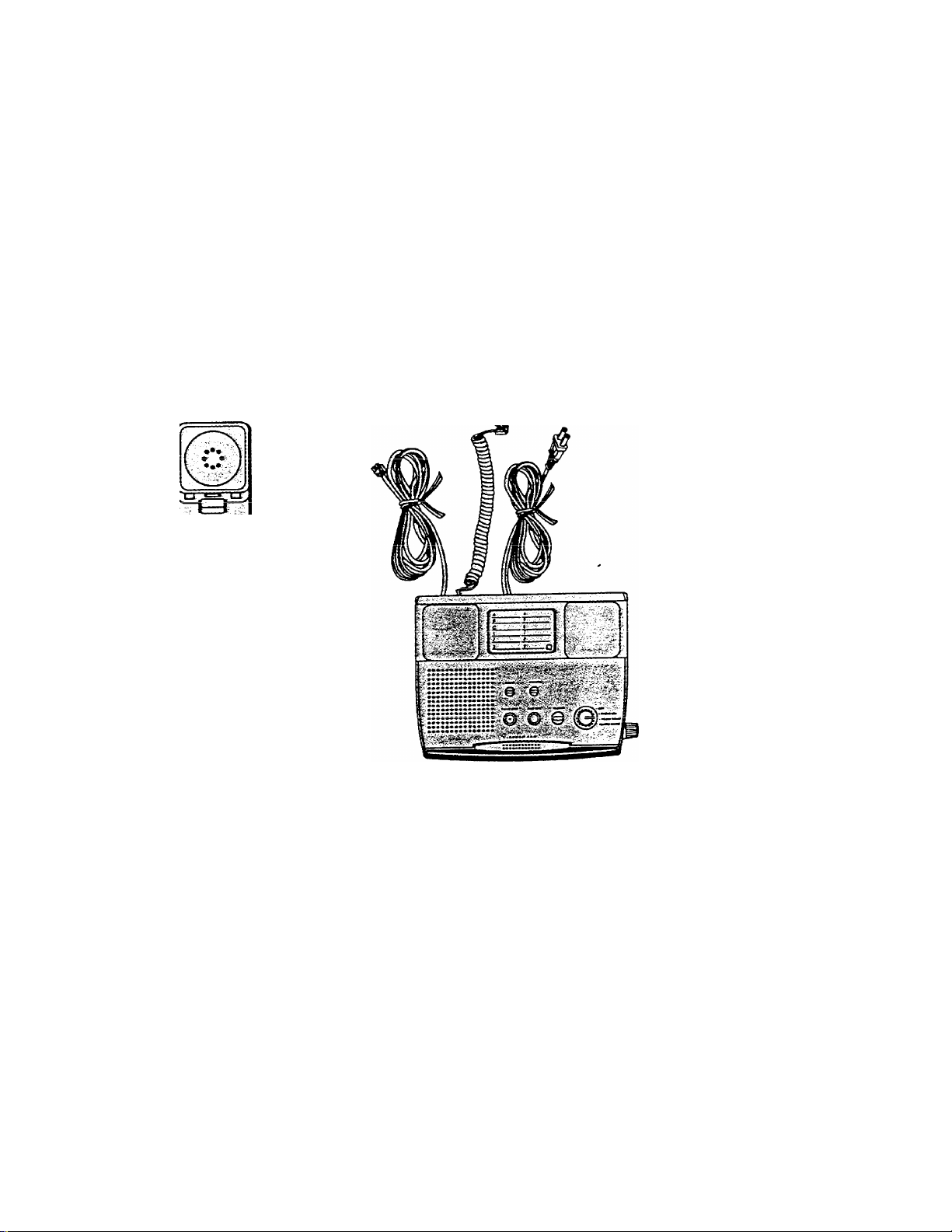
I A. Parts
Check List
I
I
/'T\
Vi/ VIB»
HANDSET
• BASE UNIT
Page 4
CONTROLS and FEATURES
/1
—
Ih
Page 5

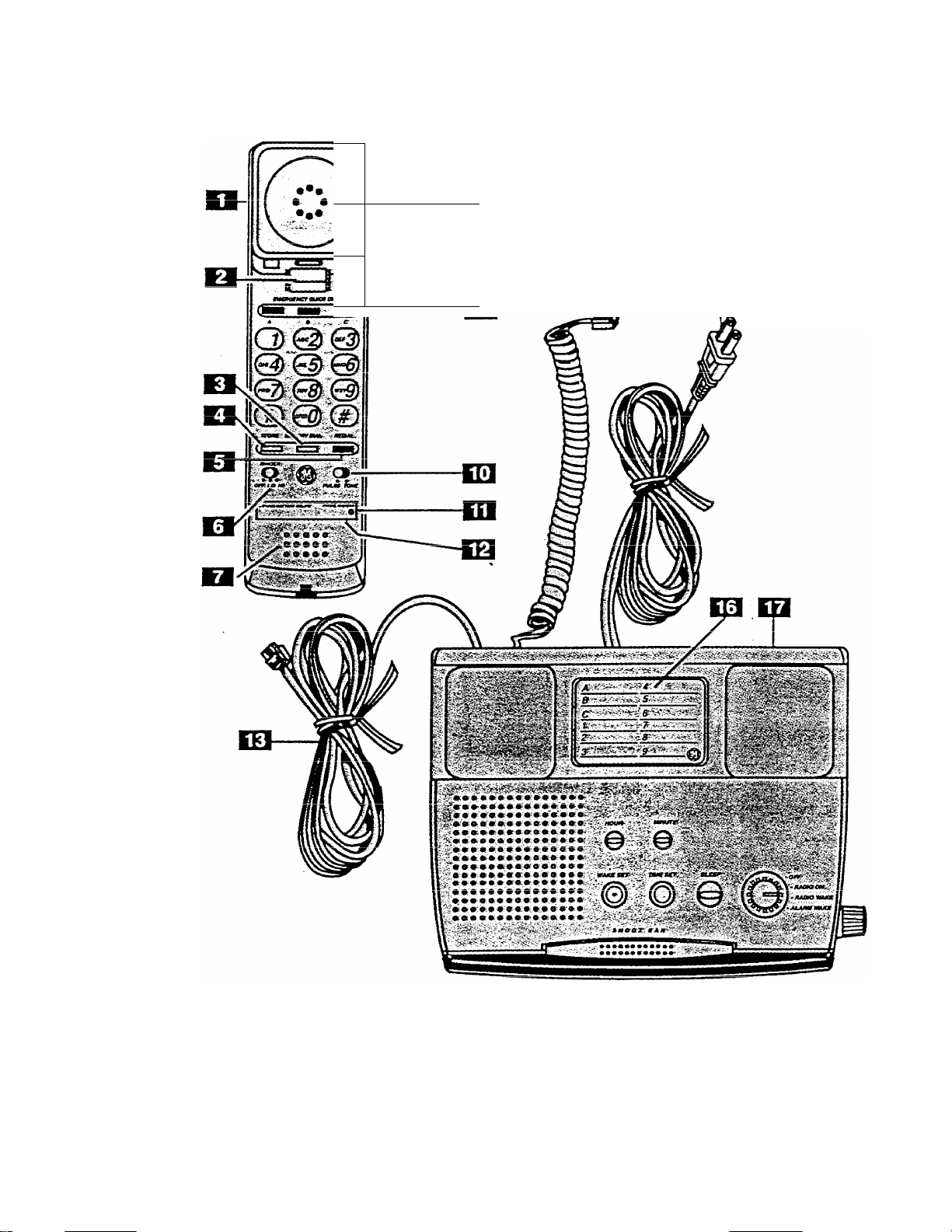
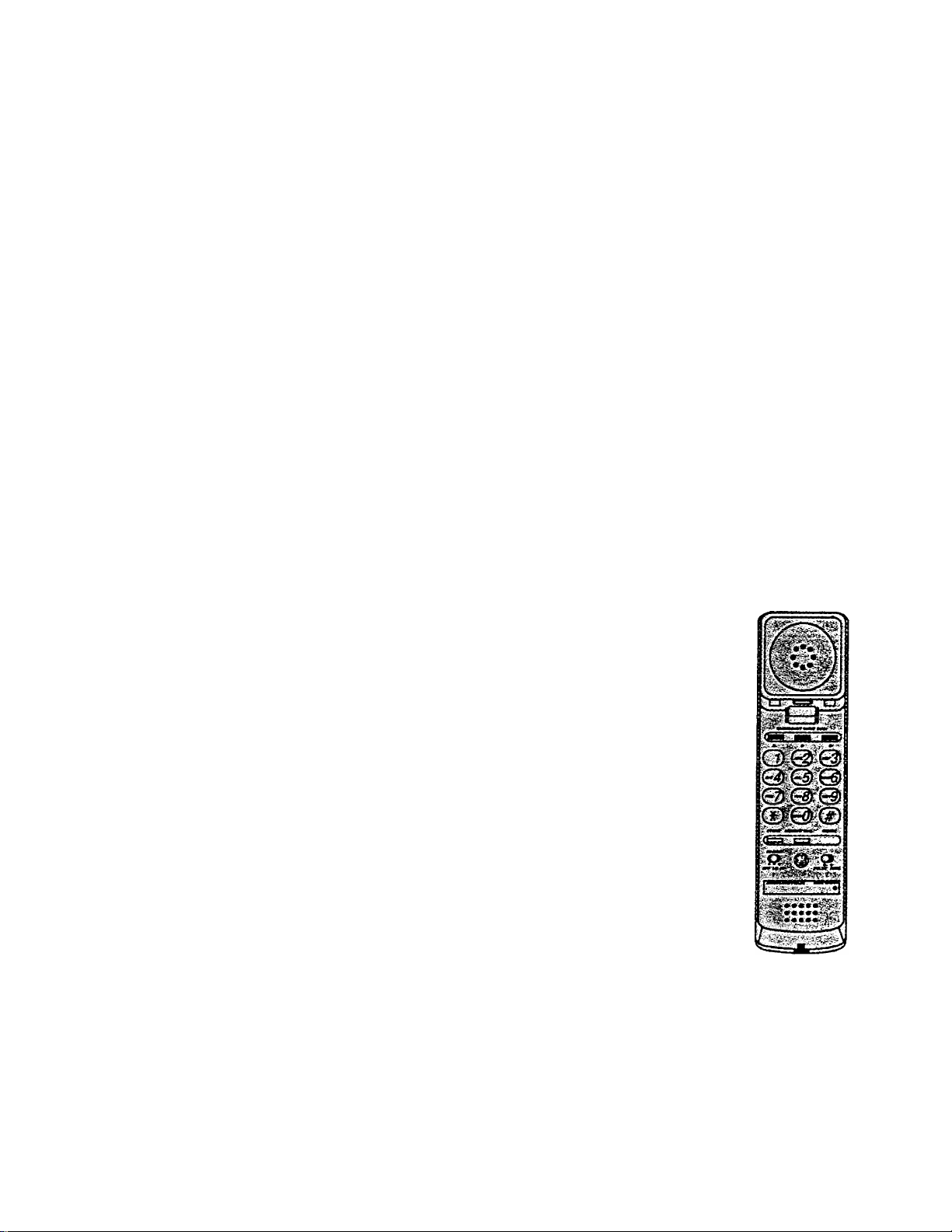
CONTROLS and FEATURES
1. Handset
2. Handset Hook Switch
3. Memory Dial Button — Used when dialing a number
stored in memory, locations 1-9.
4. Store Button — Stores phone number in a MEMORY
location.
5. Redial Button — Redials the last number called. Also
works as PAUSE for Memory after other numbers have
been dialed. ,
6. Ringer Volume Switch — Adjusts the volume of the
ringer (Hi or Lo) or to turn ringer off.
7. Microphone
8. Earpiece
9. Quick Dial Buttons — Provide instant dialing of up to 3
important telephone numbers by pressing A, B or C.
10. Dialing Mode Switch — Sets the dialing mode for either
Tone or Pulse (for rotary service).
Lithium Battery Compartment — Located on the bottom
11
of the telephone handset.
(Long-Life Lithium Battery Cartridge Is Included).
Telephone Number Display
12
13. Telephone Line Cord
14. Coiled Cord — Connects the handset to the base unit.
15. AC Power Cord
16. Memory Directory
17. Base
A.
Telephone
Controls
12 Number Memory - inciuoes positions ror une-toucjn
quick dialing for Emergency, etc. plus 9 additional memories
lUi i(t?L{Ut;iiuy liumu^i
Switchable Pulse/Tone Dialing - Touch Tone or Pulse
dialing, or any combination of Tone and .Pulse, for access to
long distance services.
I e\nrt I ifa I ithiiim Ratforv - PrnviH^-4 Mpmorv Back-UD.
к__.^UM
li.^1 ICICpiiUltC
Features
Page 6
INSTALLATION
Follow these steps to connect your new telephone
for proper operation. Make sure you have a modular
telephone jack. A modular (Universal Service Order
Code'i UFnr:- p nip / I I i I I +
-------
^ liviiw ^iHuo<j aicu; jdO/\
required.
Installatinn nf thk tolonhnno in
-
---------------- . « I,w IWI iw I* I IV^V^CUJ\JI lO yviu i ly
A
jacks or with hard-wired outlets will require additional
Converters (not included). The dealer from whom
you purchased your phone or a telephone supply
store can advise you regarding the proper Converter.
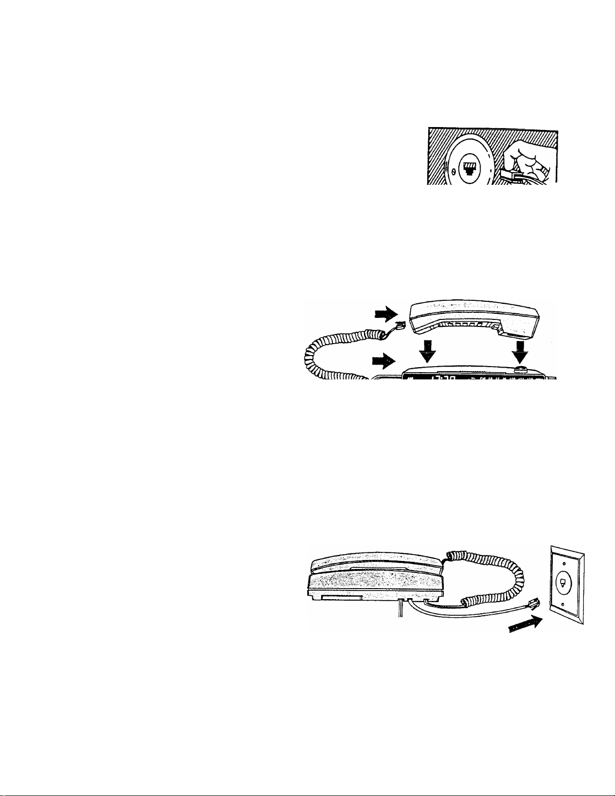
1. Connect the Coiled Cord
Plug COILED CORD into the HANDSET jack.
Place the HANDSET in the BASE.
**^UJ0r
A. Introduction
B. in.^tallatirkl
2. Connect the Telephone Line Cord
Plug the TELEPHONE LINE CORD into the
telephone outlet. An RJ11C outlet jack
(illustrated) is required. If you don’t have an
RJ11C, an adapter can be purchased from any
t^l^nKnnn
OIVJIC7.
Page 7

3. Plug in the AC Power Cord
This clock radio telephone operates on 120V
AC household power.
Plug the AC Power Cord into the AC power
outlet.
INSTALLATION
■
I
I
The Pulse/Tone Switch
The PULSE/TONE switch located on the
HANDSET should be set to the proper
position. The switch should be set to TONE if
you have “touch tone” service. Otherwise, set
to PULSE.
Note: If you have pulse service, the switch
may be changed to TONE after dialing is
completed. This allows access to phone
services that require a tone. Return switch to
is completed.
5. Ringer Volume
The RINGER VOLUME switch located on the
HANDSET can be set to the following:
HI — Maximum Volume
I n
___
OFF — Ringer is not heard
IV,/W«I II J 1^ WV./I I I^IW VWVJ.
volume
1^1
C3® ®
vj3(i{
G5®@
t/’-TK >-:v
\&&&
frr\' di nr\
[<c=3 c=t SB
I'
1.1^«« ^ wTL«
Page 8
TELEPHONE OPERATION
The GE Model 2-9710 Clock Radio Telephone provides normal
telephone operation along with storage of up to twelve telephone
numbers in memory for automatic dialing of frequently called or
emeroencv nnmhp»r<;
To Make A Call
1. Pick up HA.NDSET,
2. Wait for dial tone.
3. Dial telephone number.
4. When finished, hang-up.
To Receive a Call
1. When phone rings, pick up HANDSET and talk.
2. When finished, hang-up HANDSET.
Note: Make sure RINGER Switch is not off.
Note; HANDSET must be returned to BASE for radio play and
alarm system operation.
The telephone automatically remembers the last number dialed
fuD to 32 diaits lonol.
\-r- ----------
The number will remain in “REDIAL” until another number is
dialed.
To redial a number that you dialed press REDIAL.
—
A. Introduction
B. How to
«viMrw# ui
Receive
Calls
C3 ® @
©@@
@ @
tg=3
C. Automatic
RaHIoI
8
Page 9

TELEPHONE MEMORY OPERATION
Your now GE Mods! 2-9710 Clock Radio T6!6<^hon6 has 12
memory locations capable of storing a telephone number of up
to 16 digits. Three telephone numbers can be stored in the 3 Quick
Dial positions and dialed with one touch. (For example: you may
want to store emergency phone numbers for quick and easy
access). 9 Memory positions are dialed with two touches
{MEMORY DIAL and the number button 1-9 corresponding to'the
memory location).
Important: Before you begin storing telephone numbers in
memory you must set the PULSE/TONE switch
to the correct position.
Quick Dial Numbers
1. Pick up the HANDSET,
2. Push STORE.
3. Enter the telephone number (it will not actually call
the number in this mode).
4. Push STORE again. ■
5. Push selected Quick Dial Location — A, B or C.
6. Hang up HANDSET
7. Write the name or number of party stored in memory
1
Cxi V I I I WII j U./ I r VoT t.V^ I J WWAI'W*«
nn Piiror'+nn/
B.
IntrnHi irtinn
How to
Store
/'-Tfc.
CAUTION
WHEN MAKING TEST CALLS TO EMERGENCY NUMBERS:
1. Remain on the line and briefly explain to the
dispatcher the reason for the call before hanging up.
2. Perform such activities in the off-peak hours, such as
63fly morniny hours or ist© ©vsniriy.
Frequently Called Numbers
1. Pick up the HANDSET
2. Push STORE.
3. Enter the telephone number (it will not actually call
the number in this mode).
i uoii ti— ciyciHi.
Push key pad 1, or 2.
5.
Hang up HANDSET
6.
Write the name or number of party stored in the
7.
memory location on Memory Directory Card.
or 9 for memory location.
J?. © JL
• » • •
• • o • «
Page 10

TELEPHONE MEMORY OPERATION
Quick Dial Numbers
1. Pick up HANDSET.
2. Wait for Dial Tone.
3. Press Л or S or C.
Frequently Called Numbers in Memory
1. Pick up HANDSET
2. Wait for Dial Tone,
3. Press MEMORY DIAL
4. Press 1, or 2or 9.
This feature allows you to dial in succession a chain of
numbers in different memory locations. This is useful when
you must dial more than one number in memory to complete
a call, such as with frequent calls via an independent
service (e.g. MCI or Sprint).
For example Memory Location
Local Access Number of Long
Distance Company and 2 or 3
pauses at end, press
Authorization Code (ID), press.........................................7
Long distance phone number,
press .................................................................................. 8
........................................................
6
To Initiate Chain Dialing
1. Press MEMORY DIAL.
2. Press 6.
3. Press MEMORY DIAL.
4. Press 7.
5. Press MEMORY DIAL.
6. Press 8.
c.
How to Dial
a Stored
Number
€3) © @
Vjy \IIS/ 43/
® 0®
ГЛ
u.
now to
Chain Dial
Using the
Memory
Ож- — ■шщ)
U)
Q) ©I 0)
KZLf vcSi
Q:
tH'
?!
10
Page 11

TELEPHONE MEMORY OPERATION
When storing a number, a momentary delay may be needed in
the dialing sequence for a stored telephone number. This is
generally used when a “PAUSE” is needed to wait for a dial tone
(e.g. after dialing a long distance access number). The REDiAL
button should be pressed at the point where a pause is needed
in the dialing sequence. During storage, pushing the REDIAL
button serves to store a pause in the dialing sequence as often
Note: The REDIAL key will place a pause in the dialing sequence
anytime it is pressed sfier disling a number. When storing PAUSE
in MEMORY, each PAUSE counts as one stored digit.
Mem.ory a.nd Redial may require the use of a “PAUSE” when
initially dialing or storing outside numbers. The sequence, then,
for dialing or storing an outside number would be, for example:
9 REDIAL 123-4567
How to Change a Stored Number
Repeat the storage sequence. The new number will replace the old
number at the memory location.
How to Clear a Stored Number
Repeat the storage sequence. Skip step 3 in the sequence (i.e. do
not enter a telephone number). The storage location will be blank
when sequence is completed.
E. Storing a
Pause in
Dialing
\ü
R PABX and
PBX Use
I
I
G. Changing or
Correcting a
Stored
Number
How to Correct an Error while Storing
Simply hang up and repeat the procedure for storing from the
beginning.
¡5S' ■ '
• mSÿSÿii
11
Page 12

PRODUCT CARE
A consumer replaceable long-life Lithium Battery (3V) is
installed in the phone to provide back-up power for retaining
numbers in memory. The Lithium Battery compartment is
located on the bottom of the telephone handset.
1. Unplug the power cord and unplug PHONE LINE from
telephone outlet.
2. Remove TELEPHONE NUMBER PLASTIC COVER and
CARD to expose battery holder.
Note: Insert pointed object into hole in PLASTIC COVER
and lift. Then remove COVER and CARD.
3. Unsnap the battery door
Using a screwdriver, insert in opening at either end of
battery cartridge, pop it up, lift battery out.
Dispose of battery cartridge. Replace only with GE CAT.
f/ W ITIIWIJ UIOS./OI VJII 1^ OUIC7 K\J
them in the proper manner, according to your state and
local reoulations.
\A7h^n oiirA /Hiorsr^oa r\i
A. To Replace
Backup
Battery
ж
4. Replace battery cartridge and door
Noti»* * rinrtrirlnp ляп hfi ¡п^рг+яН nnlv nnp шяи
------------------
--------
------
-----------
«W*. . WW .. .WW.
5. Replace Telephone Number Card and plastic cover.
6. Plug in the power Cord and plug in the PHONE CORD.
Note: Numbers in memory must be reprogrammed.
For your safety, please follow these simple precautions:
• rf-4 »
u/u wvjK icjuncii^c, uioao^c;inuic, iiiuuiaic;, wti^i \ji
dispose of Battery in fire. Like other batteries of this type,
if it is burned or punctured, it could release toxic material
which could cause injury.
• Keep Battery out of reach of children.
• Replace only with GE Cat. #5-1923. Accessory Order
Form included in this guide.
^-1
pH p-r-l Uk IPVH I if f I rM I K»yH+l
12
1
B, Battery
r
Precautions
Page 13

PRODUCT CARE
To keep your GE Telephone working and looking good, follow these
few simple rules:
• Avoid putting telephone near heating appliances and devices
that generate electrical noise, (i.e., motors, fluorescent lamps.)
• Telephone should not be exposed to direct sunlight or moisture.
• • Avoid dropping the Handset and other rough treatment to the
phone.
• Clean telephone with a soft cloth dampened with water.
(Remember to first unplug phone from wall outlet)
« Never use a strong cleaning agent or abrasive powder, as this
will damage the finish.
• Retain the original packaging for future use.
The telephone line cord (from hsndset to telephone well
outlet) is one cord that can easily change its location. This
convenient feature allows you to change the location of the
cord. Your decision as to the location of the line cord will
depend on where your unit is located in reference to the
telephone outlet.
To remove line cord from current location
1. Remove MODULAR PLUG from telephone wall outlet and
HANDSET
/1
___________ J / t -rt—t r—nti !/~\K ir" o~rrj A I Kt
nemove rrom / ci.cr'ncy/vc oo'nL/ o;ny^/iv
RELIEF housing located on the bottom of the CLOCK
RADIO. '
3. Lift off HOUSING and unwrap CORD from strain relief.
To move line cord to new location (on other side of hase unit)
1, To install, WRAP CORD around the STRAIN RELIEF as
indicated and, .feplace HOUSING and SCREW. ■
2. Plug MODULAR PLUG back into telephone wall outlet
and HANDSET.
C. General
Product
Care
D. Changing
Location of
Phone Cord
fl
!—
v_
1 CORD
■
I
I
Tha fal^nhnn^ rnrH rfrnm hanri^f^t tn wall Outlet)
• f.W. WWW J..W.. ..w.www .w .ww,..--------------------
----
--------------------------------------------
is actually one cord which is easily replaced if damaged.
To replace
1. Remove MODULAR PLUG from telephone wall outlet and
HANDSET.
2. Remove SCREW from TELEPHONE CORD STRAIN
RELIEF housing located on the bottom of the CLOCK
RADIO.
3. Lift off HOUSING and unwrap cord from STRAIN
OC/ /CTCr
/ 1L-L./1»/ .
To install replacement, wrap cord around the strain relief as
indicated and, replace housing and screw.
,
E, RepiaGeable
Telephone
Cord
............
Page 14

TELEPHONE SERVICE
If your Telephone does not work properly, follow the Service Checklist. If it is still
inoperative then disconnect the Telephone and try another telephone to determine if
the problem is with the telephone line. If it is the telephone line, notify the telephone
company for service.
If the Telephone continues to malfunction, please make sure you have followed all
the instructions in this manual to correct the problem.
If you continue to have problems, refer to the service information on page 15 of this
guide and the Telephone must be disconnected.
A, Service Checklist
TELEPHONE
PROBLEM
SOLUTION
1. No Dial tone
2. Phone does not dial
3. You cannot be
heard by other party
4. Memory Dialing
Problems
5. Incoming and
Outgoing voice
volume is too low
6. Phone does not ring
7. Tone Feedback
CTIl
f iuu»^i miii^ Kjicuiii^
in pulse mode
• Check Cords to make sure they are inserted correctly.
• Does HOOK SWITCH extend fully when handset is
removed from cradle?
• Check PULSE/TONE switch. Place in the PULSE
Dosition.
1
---------------
• Check that handset coil cord is fully inserted at both
ends.
• Did you program number correctly?
• Did you follow the proper dialing sequence?
• Check that other phones are off hook at the same time, if
so, this is a normal condition as volume drops when
additional phones are used at once.
• Is RINGER SELECT set to OFF position?
• Are you using too many phones on one line? The total
REN of all phones should not be greater than the
maximum REN for your calling area. (Usually maximum
REN is 5. See FCC Registration Information on page 16.)
• This is normal as power is fluctuating with phone out-
r\i ilcmn
pMlWII 1^.
8. Loss of Memory
14
• Is battery installed correctly? *
• Does battery need to be replaced?
Page 15

TWO YEAR
LIMITED WARRANTY TELEPHONE
What does your warranty cover?
• Any defect in material or workmanship.
For how long after the original purchase?
• Two years.
• The warranty for rental units begins with the first rental.
What will we do?
• Provide you with a new, or at our option, a reconditioned unit.
• The exchange unit is warranted for the remainder of your product’s original two-year warranty period.
How do you make a warranty claim?
• Properly pack your unit. Include any cables, etc., which were originally provided with the product. We
recommend using the original carton and packing materials.
• Include in the package a copy of the sales receipt or other evidence of date of original purchase. If the
unit was a gift, provide a statement specifying the date received. Also print your name and address and
a description of the defect.
• Ship the unit standard UPS or equivalent to:
Thomson Consumer Electronics, Inc.
Product Exchange Center
32 Spur Drive
El Paso, Texas 7^906
• Pay any charges billed to you by the Exchange Center for service not covered by the warranty.
• A new or reconditioned unit will be shipped to you prepaid freight.
What does your warranty not cover?
• Customer instruction. Your Owner’s Manual provides information regarding operating instructions and
user controls. For additional information, ask your dealer.
• Installation and set-up service adjustments.
• Batteries.
• Damage from misuse or neglect.
• Product which have been modified or incorporated into other products.
• Product purchased or serviced outside the USA.
How does state law relate to this warranty?
• This warranty gives you specific legal rights, and you may also have other rights which vary from state
to state.
What if you purchased your unit in Canada?
• Refer to the Canadian Warranty.
For products purchased outside the United States and Canada, see dealer for warranty.
Thomson Consumer Electronics, Inc.
SERVICE INFORMATION
FCC requires this product be serviced only by the manufacturer or its authorized service agents. In
accordance with FCC requirements, changes or modifications not expressly approved by Thomson
Consumer Electronics could void the user’s authority to operate this product. For instructions on how
to obtain service, refer to the warranty included in this Guide or call customer service, telephone
number: 800-448-0329.
Attach your sales receipt to the booklet for future reference or jot down the date this product was
purchased or received as a gift. This information will be valuable if service should be required during
the warranty period.
Purchase date
Name of store
15
Page 16

FCC REGISTRATION INFORMATION
Your GE telephone equipment is registered with the Federal Communications Commission and is in
compliance with parts 15 and 68, FCC Rules and Regulations.
1. Notification to the Local Telephone Company
On the bottom of this equipment is a label indicating among other information, the FCC Registration
number and Ringer Equivalence Number (REN) for the equipment. You must, upon request, provide
this information to your telephone company.
The REN is useful to determine the number of devices you may connect to your telephone line and still
have all these devices ring when your telephone number is called. In most (but not all) areas, the sum
of the REN’s of all devices connected to one line should not exceed 5. To be certain of the number of
devices you may connect to your line as determined by the REN, you should contact your local telephone
company.
NOTES; This equipment may not be used on coin service provided by the telephone company.
Party lines are subject to state tariffs, and therefore, you may not be able to use your own telephone
equipment if you are on a party line. Check with your local telephone company.
Notice must be given to the telephone company upon permanent disconnection of your telephone from
your line.
2. Rights of the Telephone Company.
Should your equipment cause trouble on your line which may harm the telephone network, the telephone
company shall, where practicable, notify you that temporary discontinuance of service may be required.
Where prior notice is not practicable and the circumstances warrant such action, the telephone company
may temporarily discontinue service immediately. In case of such temporary discontinuance, the telephone
company must; (1) promptly notify you of such temporary discontinuance, (2) afford you the opportunity
to correct the situation and (3) inform you of your right to bring a complaint to the Commission pursuant
to procedures set forth in Subpart E of Part 68, FCC Rules and Regulations.
The telephone company may make changes in its communications facilities, equipment, operations of
procedures where such action Is required in the operation of its business and not inconsistent with FCC
Rules and Regulations. If these changes are expected to affect the use or performance of your telephone
equipment, the telephone company must give you adequate notice, in writing, to allow you to maintain
uninterrupted service.
INTERFERENCE INFORMATION
This device complies with Part 15 of the FCC Rules. Operation is subject to the following two
conditions: (1) This device may not cause harmful interference, and (2) This device must accept any
interference received, including interference that may cause undesired operation.
This equipment has been tested and found to comply with the limits for a Class B digital device,
pursuant to Part 15 of the FCC Rules. These limits are designed to provide reasonable protection
against harmful interference in a residential installation.
This equipment generates, uses and can radiate radio frequency energy and, if not installed and used
in accordance with the instructions, may cause harmful interference to radio communications. However,
there is no guarantee that interference will not occur in a particular installation.
If this equipment does cause harmful interference to radio or television reception, which can be
determined by turning the equipment off and on, the user is encouraged to try to correct the
interference by one or more of the following measures:
• Reorient or relocate the receiving antenna (that is, the antenna for radio or television that is "receiving"
the interference).
• Reorient or relocate and increase the separation between the telecommunications equipment and
receiving antenna for radio or television that is "receiving” the interference).
• Connect the telecommunications equipment into an outlet on a circuit different from that to which
the receiving antenna is connected.
• Consult the dealer or an experienced radio/TV technician for help.
If these measures do not eliminate the interference, please consult your dealer or an experienced
radio/television technician for additional suggestions. Also, the Federal Communications Commission
has prepared a helpful booklet, "How 7b Identify and Resolve Radio/TV Interference Problems”. This
booklet is available from the U.S. Government Printing Office, Washington, D.C. 20402. Please specify
stock number 004-000-00345-4 when ordering copies.
HEARING AID COMPATIBILITY
This telephone system meets FCC standards for Hearing Aid Compatibility.
16
Page 17

CONTROLS and FEATURES
A.
Clock Radio
f
\ ^
ic_
f' ■ - r . -
...'.: Ш-.
iz^
4'- ■
5
S
Controls
and
Features
Ш
^ ^ ■ * ■•■ ■ ' -■■■ - - ■ -■■ --------
,‘ii* »«*»***■? #WW^W -i
3«'« * •.•5«;«W«t*:***«
L
J.
Ш'И
:»# Il
SrL
Note: Radio
and Alarm will
not operate if
LJ A Mr^er^^T :_
n/M'^UiDCI 15
out of BASE
1. Hour Button
2. Minute Button
3. Wake Set Button
4. Time Set Button
5. Sleep Button
6. Function Selector
,''ojf
• Radio On
• Radio Wake
• Alarm Wake
7. Snooz Bar
8. LED Indicator
• AM
• Wake
9. Digital Display
10. FM/AM Dial Scale
11. Volume Control
12. Tuning Wheel
I
I
■
13. FM/AM Band Switch
14. Radio Mute Switch
17
Page 18

CLOCK RADIO OPERATION
The GE Model 2-9710 Clock Radio Telephone provides good
sound quality with its AM/FM radio. In addition, it provides
convenient alarm features, such as wake-to-radio, wake-toaiarm, sieep-to-music and snooz alarm.
When AC power is interrupted (disconnected) for a short
period, both time and alarm settings will change (unless
optional battery is installed).
(reconnected) the DIGITAL DISPLAY will blink to indicate that
nnvA/pr wp<; intPrriintpH pnH unii rppHii/^t thp TIMF and
After AC power ¡s restored
ALARM settings. To stop display from blinking, press TIME
SET button and HOUR or MINUTE button at the same time.
(See 'WO WORRY'’ BATTERY BACKUP SYSTEM.)
Note: Radio and alarm will not operate if telephone
handset is out of cradle.
1. Turn the FUNCTION SELECTOR to ON.
2. Select AM or FM broadcasts using the BAND switch.
3. Select a station with TUNING Wheel and adjust the VOLUME
CONTROL to your preferred listening loudness.
Turn radio OFF by turning the FUNCTION SELECTOR to OFF.
4.
A. Introduction
D, Power
Failure
indicator
T
C. Radio
Operation
When the telephone handset is removed from the cradle, the
radio’s audio Is automatically muted, eliminating' the need to
manually reduce radio volume to carry on a conversation.
The HANDSET must be returned to the BASE for radio
play and alarm sysiem uperaiiuri.
The built-in Automatic Frequency Control (AFC) works to
rariitna Hrift nn FM rp/^pntir>n anH hpln« kppn thp radio
locked in on the station to which it is tuned. AFC works only
on FM.
18
D. Automatic
Radio
Muting
Page 19

r'I r\r*W r> A nuy^ .
nMi^iw urcMAIIUN
^ Built-in ferrite rod antenna eliminates the need for
an outside antenna for AM reception. Rotating the radio
slightly may improve reception for distant AM stations.
POWER CORD acts as your FM antenna. The
POIA^ER CORD picks up moderate to strong stations and
eliminates the need for an external antenna in most strong
signal areas. Be sure the POWER CORD is stretched out to
its full length. Do not coil or bunch the CORD together.
Changing position of the POWER CORD may improve
I ^ wwpuvyi I.
Your DIGITAL CLOCK TIMER operates on a 24-hour cycle.
The AM indicator to the left of the digital display will show
when the clock is. reading AM time.
1. Press and hold TIME SET button.
2. While holding the TIME SET button, press the HOUR and
MINUTE buttons to change the display to the exact AM or
PM time.
For a display of time in minutes and seconds;
1. Press and hold the WAKE SET button.
2. While holding the WAKE SET button, momentarily press
the SLEEP button.
• The hour digits will display minutes.
• The minute digits will display seconds and start to
increment.
Release the WAKE SET button to return to the hour and
mintitc» Hicnlai/
.....
.
r. Antennas
G. Time Set
H. Minutes and
Seconds
Time
To Set The Wake Time, Select the AM or PM time that
you want your radio or alarm to turn on automatically by
following thesb simple steps:
1. Turn the FUNCTION SELECTOR to OFF position.
o I..j:M.... *u.» i/kfA ij't— r^r—r i_, .jj.
c.. yvMiic iiuiuiiiy inti vv/M\c od Dunon, press me nuut-i ana
MINUTE buttons to change the display to your desired AM
or PM wake-up time.
3.
Release the WAKE SET button and the current time is once
again displayed.
_______________________
_____
t »>.-», 1
I. Wake Time
I
I
19
Page 20

CLOCK RADIO OPERATION
Your Choice of Wake to Radio
1. Select your AM or FM station as outlined under RADIO
OPERATION.
-r.
__
¿1. lurri ¡ OCLCO/L/n lU Kjrr.
3. Set wake time as outlined under SET THE WAKE TIME.
4. Turn the FUNCTION SELECTOR to .RADIO WAKE position.
The radio is now set to turn on at the time you have set, and will
turn itself off after about 1 hour and 59 minutes. To turn radio off
sooner, turn FUNCTION SELECTOR to OFF position.
Or Wake to Alarm
2. Turn FUNCTION SELECTOR to ALARM WAKE position.
The alarm will turn on at the time you have set and will sound for
about 1 hour and 59 minutes, then turn itself off. To turn alarm off
SUUI ICI, lUJ H U 1C /“«-/< I IV^IV
r*i Í A I c'r~i r~/^-rr^n /Ocrcr
• The WAKE INDICATOR in the Display will light.
Set wake time as outlined under SET THE WAKE TIME.
• The WAKE INDICATOR in the Display will light. ^ ^
C/ IKir'-rir^M OC/ t/n, r\^P
I \^l I \.\J I
.
NOTE; Your radio has a 24 hour timer. When FUNCTION SEL
ECTOR is left in WAKE TO ALARM or WAKE JO RADIO mode,
it will turn itself on, sound for approximately 2 hours, turn itself
off, and turn on again at the same time the following day.
J.
Wake to
Music or
Radio
SLEEP TO RADIO
You can drift off to sleep listening to the radio with the knowledge
that the radio will turn itself off automatically.
1. Turn FUNCTION SELECTOR to OFF.
2. Press and hold the SLEEP button. ""
I ne uispiay will exhibit
SLEEP time of 0.59.
0 Dr-Qoo tha hAiM! ITr hiit+nn tn cot cloon timp hfttwfien 59 and
O. I I coo UlC nriflTWI^ ILWI I W wwvwiwj-r - -- -
0 minutes, depending on how long you wish the radio to play.
For sleep time of more that 59 minutes, up to 1 hour 59
minutes, momentarily press the HOUR button (while holding
the SLEEP button), the display will exhibit 1:59. Then, press
the MINUTE button to select the desired amount of sleep
time In excess of 1 hour.
1 l-»_l________il
4. Heiease tne OLCCr uuuun. I ne Liuncm umc lo ..Ay«...
____
i-n r~r—rt \^. .u..... TU.-. tinru-l /^nr*o onain
displayed.
5. The radio Is now on and you ca.n select your station in the
usual way. The radio will play for the chosen length of time
(up to 1 hour and 59 minutes), and will then turn itself off. If
you decide to turn the radio off before the total number of
minutes have passed, just press the SA/OOZ button.
20
K. Sleep to
the Radio
Page 21

CLOCK RADIO OPERATION
с/ CCD тп a Л run лмп и/лк'с тп о л пт па WAk’P ТП А! ARM
I ЧУ / 1^4У/ЧУ f ЬУ Г ГУ^/ЛА. # W i 1У1АУ1Ч/ ЧУ • J W шг^кш Я*» ш w швшш
You сап set your dock radio to lull you to sleep, turn itself off, then
awaken vou at a present time, all automatically. Follow the steps under
WAKE lb RADIÒ or WAKE Ю ALARM, then proceed as in SLEEP Ю
RADIO instructions, steps 2 thru 5.
The push button control for Snooz-Alarrn has two functions:
1. To take an extra nap after the alarm sounds or the radio comes
on in the WAKE mode, simply press the SNOOZ-ALARM push
button to silence the radio or alarm. About 9 minutes later the
radio or alarm will sound again. You can turn the unit off or use
the SNOOZ-ALARM feature for up to 1 hour and 59 minutes,
after which the radio or alarm will turn itself off until the next day.
J.1__
z. II snuib un inu oLccr uyau и under SLEEP TG
^ О t /—r**ri ^
_______________
________________
I _ —
^_л.
_____
________________
RADIO).
This radio is equipped with a memory holding system that can be
nnu/oroH \A/ith a r'l ictnmor-inc+allisW Q_unlt hat+orv inrit ini'll irlpH^ WhAn
VT wi SiT w f ¥ Mil I Ipft W V«S|I%WI II •W\MMV»VI W v \/l ^ W«»VWI
normal household power is interrupted, or AC line cord is unplugged,
the battery will power the radio to keep track of time and alarm settings
programmed into memory. When on battery power, the digital display
will not light, but the radio will play and alarm will operate. Normal
operation will resume after AC power is restored so you will not have
to reset time or alarm.
K. Sleep to the
Radio cont.
L. Snooz-
Alarm
M. “No-Worry’
J
Raitorvr
IW* n ■ «. s'«.« - -
Backup
Svstem
--- - -- - -- - -- - -- - -- -
--- - -- - -- - -- - -- - -- -- - -- - -- -- -- - -- - -- -- - -- - -- - -- - -- - -- -
Install battery as follows:
1. Remove battery compartment door (located on bottom of radio)
by applying thumb pressure to area indicated on battery door
and then sliding door off cabinet.
2. Connect a 9-volt battery connector. The power failure protection
circuit will not operate unless battery is installed.
3. Insert battery in compartment and replace compartment door.
Note: Alkaline battery, NEDA 1604A, is recommended for memory
holding time. Carbon-zinc battery (NEDA 1604) may be used but
memory holding time will be substantially reduced.
Memory holding time for a fresh alkaline battery is approximately 6
hours (if radio or alarm are not operated), which should take care of
short, nuisance-type AC power failures. To preserve battery life, the
I aUlW Ql I^UIVi I Cl I ICUI I II IIW »1 I /”\W / w Jr
its voltage will drop and memory may be lost. Be sure to replace the
battery periodically. Battery is not included with this clock radio.
IMPORTANT: Be sure to remove battery when storing the set. Battery
will be drained if left connected when set is unplugged. A leaky battery
can badly damage the clock radio.
liH rûnrï^în i^li in+/> on A.r^. m rflckf Ac tho hiittprv npfc olrfpr
■
I
I
21
Page 22

1 J f \ / ^ A
I WU Y tAhi
LIMITED WARRANTY
What do«3 your warranty cover?
• Any defect in materiai or workmanship.
For how long after the original purchase?
• Two years.
• The warranty for rental units begins with the first rental. .
What will we do?
• Provide you with a new, or at our option, a reconditioned unit.
• The exchange unit is warranted for the remainder of your product's original one-year warranty
period.
How do you make a warranty claim?
• Properly pack your unit. Include any cables, etc,, which were originally provided with the product.
\AJa rar*r\rr\manA i lern/^ fha nrtnin^l n^rfnn anH nar'lfinn matAfiai^
fTW I
• Include in the package a copy of' the sales receipt or other evidence of date of original purchase. If
the unit was a gift, provide a statement specifying the date received. Also print your name and
address and a description of the defect.
• Ship the unit standard UPS or equivalent to:
Thomson Consumer Electronics, Inc.
Product Exchange Center
32 Spur Drive
Cl "7QQAA
k_i I f
• Pay any charges billed to you by the Exchange Center for service not covered by the warranty.
• A new or reconditioned unit will be shipped to you prepaid freight.
What does your warranty not cover?
• Customer instruction. Your Owner's Manual provides information regarding operating instructions
and user controls. For additional inforrfiation, ask your dealer.
• Installation and set-up service adjustments.
• Batteries.
• OSmaQ® from miSLiSG OT flOQiBCt.
• Products which have been modified or incorporated into other products.
• Product purchased or serviced outside the USA. •
How does state law relate to this warranty?
• This warranty gives you specific legal rights, and you may also have other rights which vary from
state to state.
What If you purchased your unit in Canada?
• Refer to the Canadian Warranty.
For products purchased outside the United States and Canada, see dealer for warranty.
11^1
iva iiiv wi IV* i
1
Thomson Consumer Electronics. Inc,
CCDUir'C
Vjk.1 1 T I Wk.
TTKic. ear\/i/^oH oni\/ h»\y thosA soeotellv trained in aoorooriate servicing techniques.
For instructions on how to obtain service, refer to the warranty included in this Guide.
Attach your sales receipt to the booklet for future reference or jot down the date^^i^ product was
purchased or received as a gift. This information will be vaiuabie if service should be required during
the warranty period.
Purchase date __________________________________________________________________________________
Nam.s of store_________________________—------------------------------------------------------------------------------—
------------
22
Page 23

23
I
Page 24

ACCESSORY OROFR FORM
Tq fulfill your communicating needs and enhance your
lifestyle, a wide range of GE extension phones, main
vhones. cordless ohones and answering systems is
* '
/ " C
_7
available.
Just stop by your nearest retailer and ask to see the
wide range of GE telephone products.
All are carefully engineered to offer you high quality
and dependability, modern easy-to-use features, and
elegant styling at an affordable price.
Should you wish to purchase, insist on the GE brand
for all your communicating needs.
mm
Page 25

2-9710
ACCESSORY ORDER FORM
rATAI nn NMWnFP npprniPTinw PRICF FArH
LITHIUM CARTRIDGE
LiMnu2 ceii, 5 volt
5-1923
(CR2032) For Models
$6.70
with “.ME.MORY
STORE”.
For credit card purchases
Your complete charye card number, its
expiration date and your signature are
necessary to process all charge card orders.
Copy your complete account number from your
VISA card.
My card expires:
Copy your complete account number from your
MasterCard,
Copy the number above your
name on the MasterCard
Shipping, Handling, and Insurance $ 5.00
Total Amount Enclosed
Use VISA or MasterCard preferably. Money order
or c.heck .must be in U.S. currenc'^ on!'^. No COO
or CASH. ^ "
All accessories are subject to availability. Where
Prices are subject to change without notice. Mail
order form and money order or check (in U.S.
currency) made payable to Thomson Consumer
Electronics, Inc. to:
Consumer Electronics
Mail Order Department
P.O. Box 8419
Ronks, PA 17573-8419
This is your return label. Please print clearly.
To:
QUANTiTY TOTAL
........................
$ __________
My card expires:
Authorized Signature
Prices are subject to change without notice.
Total Merchandise
Sales Tax
We are required by law to collect the appropriate sales
tax for each individual state, county, and locality to
which the merchandise is being sent.
................................................
.................................
$
_______
$
_______
Name
Address
City
____
Please make sure that this form has been filled
out completely.
CUSTOMER; CUT ALONG DOTTED LINE.Cl/'
State ZIP
Apt.
Page 26

Model 2-97WA
349A1585-0001 (Rev. 2)
93-45
Printed in Malaysia
 Loading...