

Page 1
—
——
——
—
—
—
—
—
—
——
——
—— —-—
—
—— ———
—
—— —
—
—— —
—
—— —
—
—— —_—_
—
—— —
—
—-
—
—
—
—
—
—
—
—
—
—
—
—
—
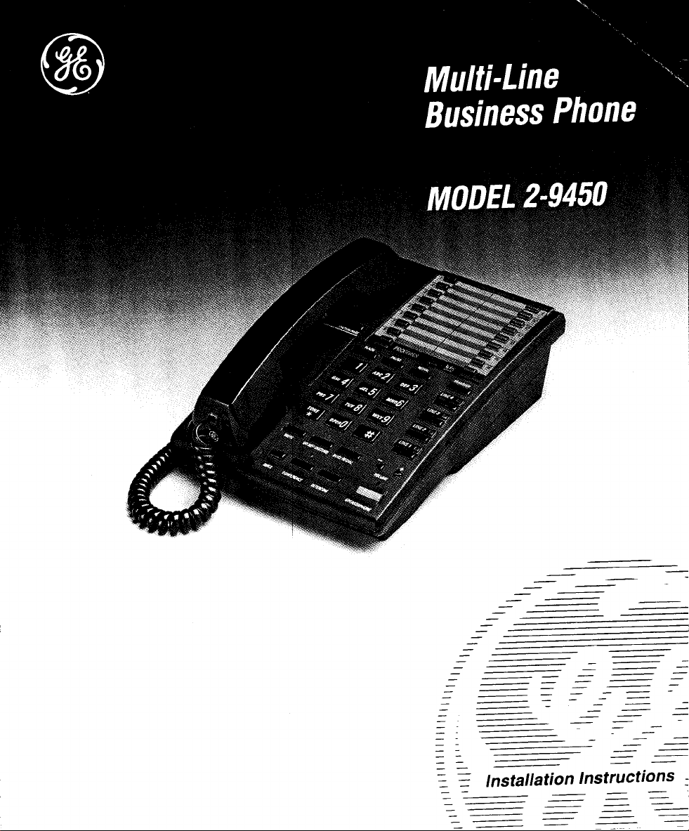
. ~ Installation Instructions =
—
—
——
—
——— ———
—
—
—
—— .
—
—
——
——
——
—— —
—— —
—— —
—-
—
—
—
—
—
—
—
—
——
——
—
——
——
=
—
Page 2
BEFORE YOU BEGIN . . .
The GE model 2-9450 is a multiple line business telephone that is
designed for easy installation in your home or office.
However, it is important that you follow these few simple guidelines.
■ Take a few minutes to read this material so that you thoroughly
understand the sequence of steps to be followed for proper installation
of your GE 2-9450 telephones.
■ As you read the instructions you may require additional line cords or
other components not included with this product. These items will be
indicated by this symbol: (not provided).
■ These Installation Instructions have been designed for installation only
of your GE 2-9450 telephone system. The separate Use and Care
Guide provides easily understood directions for operation after
installation.
Retain your working copy of these Installation Instructions for
future reference when adding stations or making changes to your
system.
IMPORTANCE OF INSTALLING A 9V BATTERY
Your GE Multi-Line Business Phone has been designed to accept a 9V
Alkaline Battery (Not Provided) for two very important reasons. First, it
provides backup power to allow you to use the telephone in the event of
an AC power outage. Second, should there be a power outage, or if the
AC power supply is disconnected, all numbers in memory and any other
stored information will be preserved until AC power is restored.
Battery installation procedures are explained in both Step 3 (Installing
Desk or Table Top Telephones) and Step 4 (Installing Wall Mounted
Telephones). Please follow these procedures carefully. Carefully remove
the unit from the package. Check this list to be certain all components
are included.
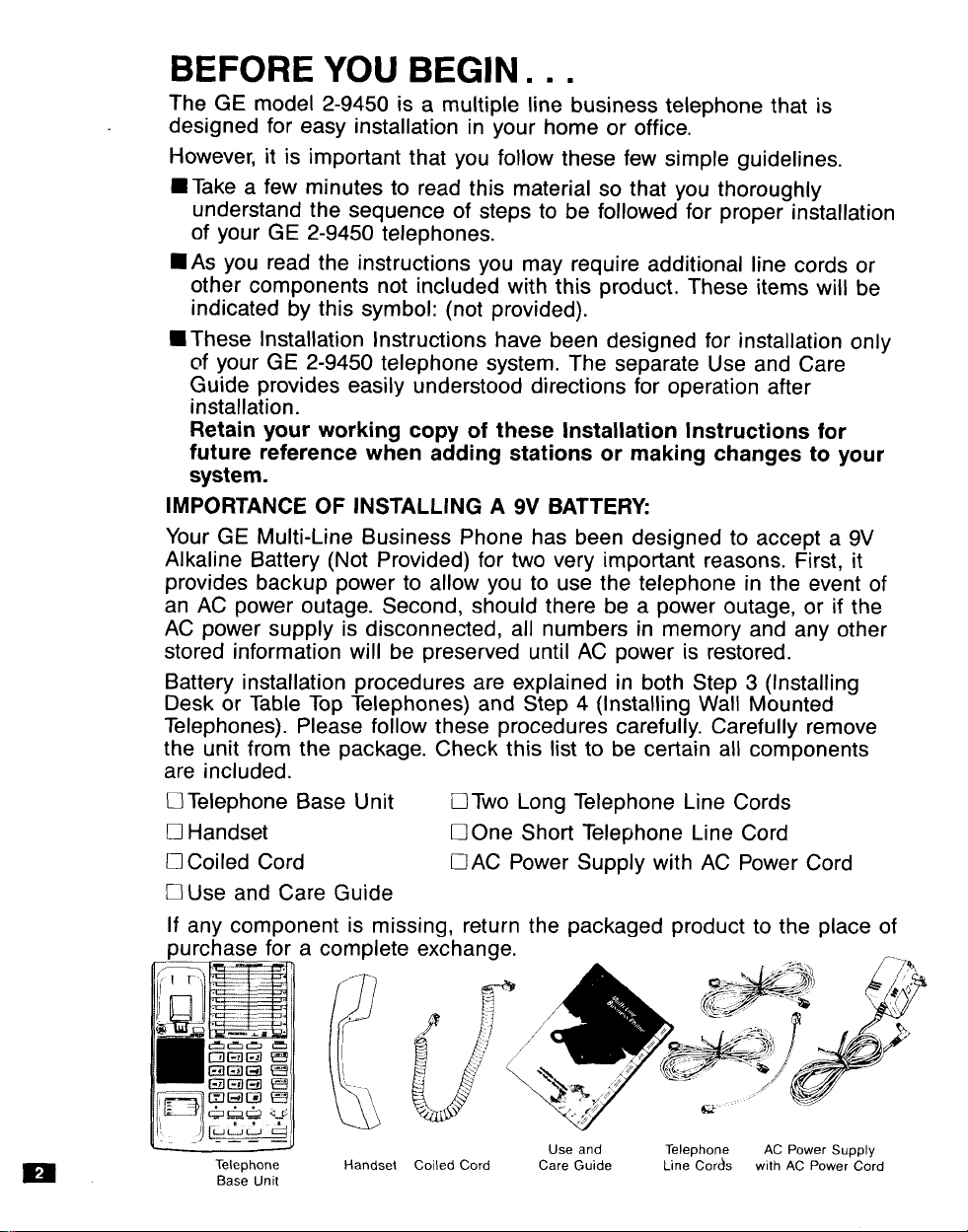
D Telephone Base Unit ❑ Two Long Telephone Line Cords
D Handset ❑ 0ne Short Telephone Line Cord
U Coiled Cord UAC Power Supply with AC Power Cord
❑ Use and Care Guide
If any component is missing, return the packaged product to the place of
purchase for a complete
.-
B
$
““”-\
[
Telephone Handset Coiled Cord
Base Unit
Use and
Care Guide tine’ COrds with AC Power Cord
Teleohone AC Power
SUDDIV
,.,
Page 3
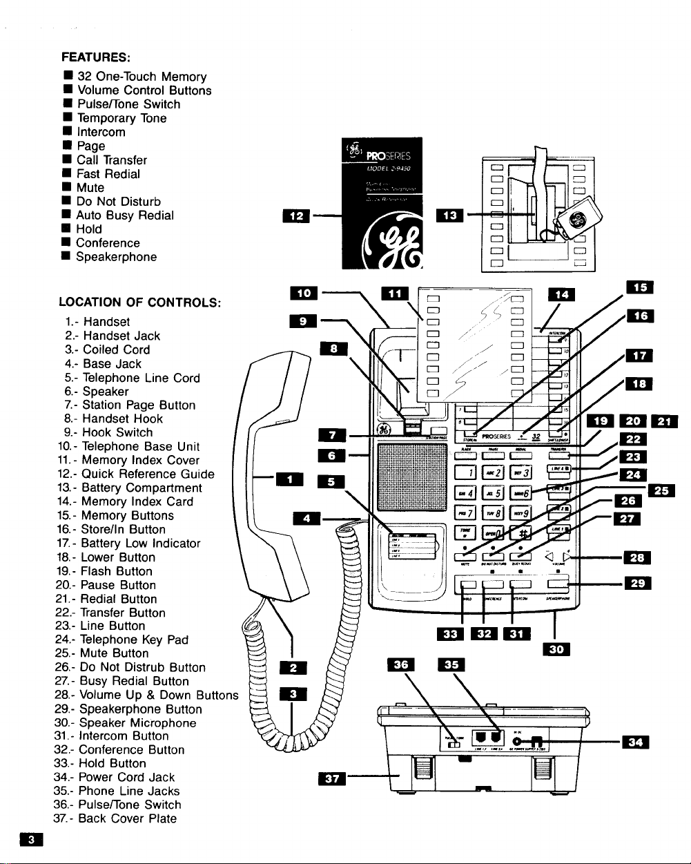
FEATURES:
■ 32 One-Touch Memory
9 Volume Control Buttons
9 Pulse~one Switch
■ Temporary Tone
■ Intercom
■ Page
■ Call Transfer
■ Fast Redial
■ Mute
■ Do Not Disturb
■ Auto Busy Redial
❑ Hold
■ Conference
■ Speakerphone
LOCATION OF CONTROLS:
1.- Handset
2.- Handset Jack
3.- Coiled Cord
4.- Base Jack
5.- Telephone Line Cord
6.- Speaker
7.- Station Page Button
8.- Handset Hook
9.- Hook Switch
10.- Telephone Base Unit
11.- Memory Index Cover
12.- Quick Reference Guide
13.- Battery Compartment
14.- Memory Index Card
15.- Memory Buttons
16.- Store/In Button
17.- Battery Low indicator
18.- Lower Button
19.- Flash Button
20.- Pause Button
21.- Redial Button
22.- Transfer Button
23.- Line Button
24.- Telephone Key Pad
25.- Mute Button
26.- Do Not Distrub Button
27.- Busy Redial Button
Volume Up & Down Buttons
28.-
29.-
Speakerphone Button
30.-
Speaker Microphone
Intercom Button
31.Conference Button
32.Hold Button
33.Power Cord Jack
34.Phone Line Jacks
35.Pulse~one Switch
36,-
Back Cover Plate
37.-
/ //
Page 4
1.
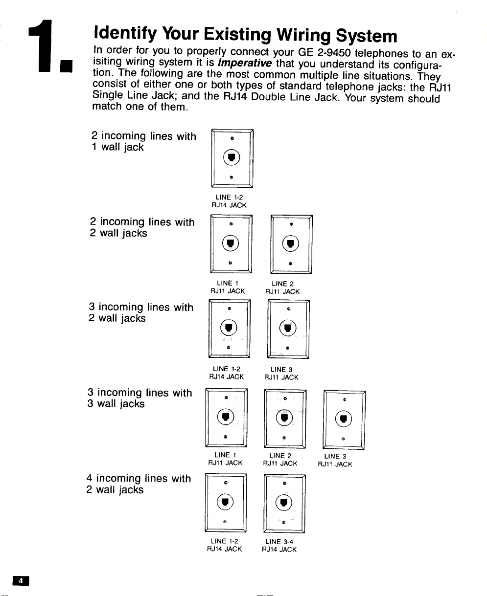
Identify Your Existing Wiring System
In order for you to properly connect your GE 2-9450 telephones to an ex-
isiting wiring system it is imperative that you understand its configuration. The following are the most common multiple line situations. They
consist of either one or both types of standard telephone jacks: the RJ1l
Single Line Jack; and the RJ14 Double Line Jack. Your system should
match one of them.
2 incoming lines with
1 wall jack
2 incoming lines with
2 wall jacks
3 incoming lines with
2 wall jacks
3 incoming lines with
3 wall jacks
4 incoming lines with
2 wall jacks
@
c
o
e
U
LINE 1-2
RJ14 JACK
e
m
o
@
u
LINE 1
RJII JACK
e
w
o
@
a
LINE 1-2
RJ14 JACK
@
w
o
0
u
LINE 1
RJII JACK
a
w
o
m
a
LINE 1-2
RJ14 JACK
LINE 2
RJ1l JACK
LINE 3
RJ1l JACK
LINE 2
RJ1l JACK
LINE 3-4
RJ14 JACK
LINE 3
RJ1l JACK
m
Page 5
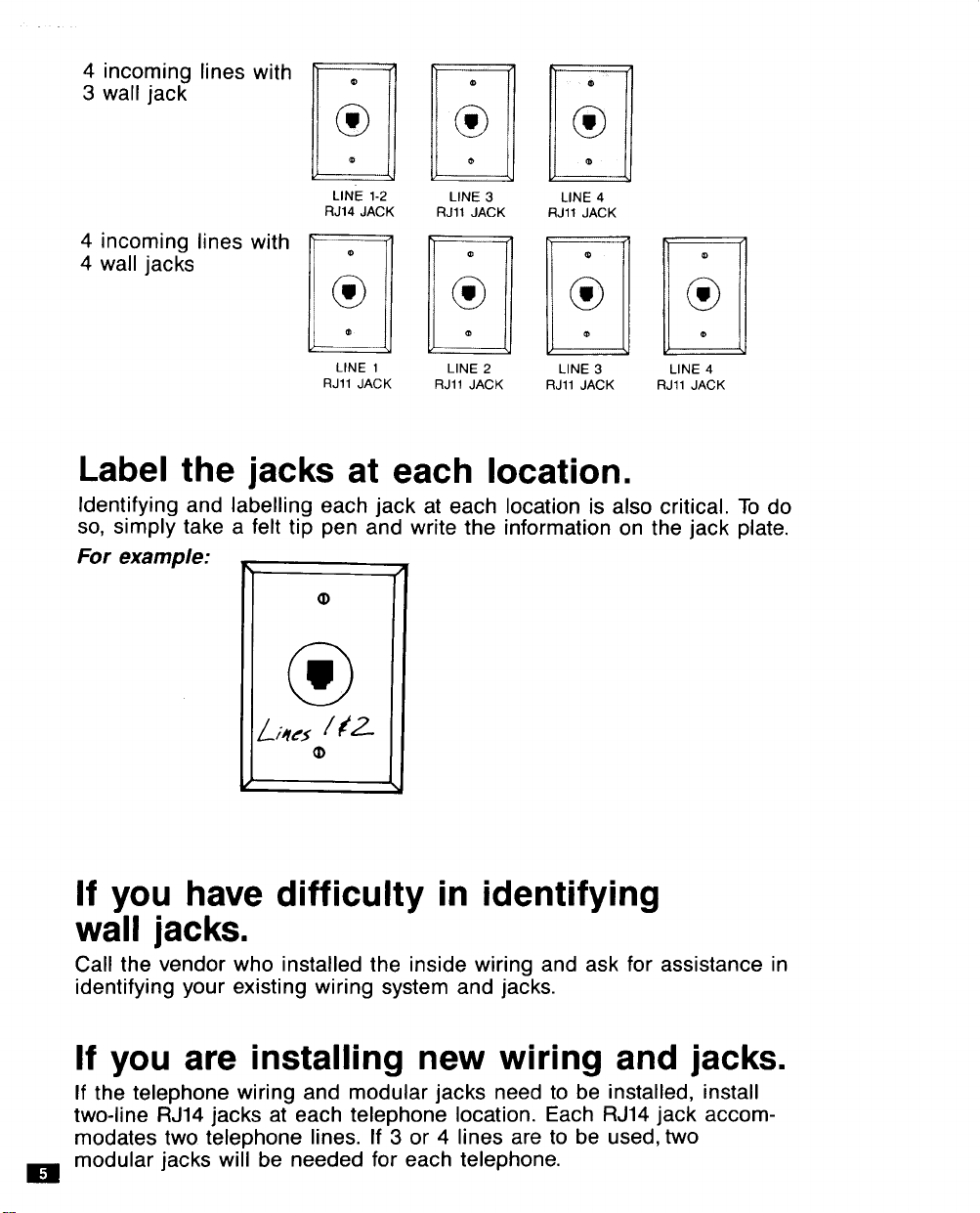
4 incoming lines with
3 wall jack
4 incoming lines with
4 wall jacks
u
LINE 1-2
RJ14 JACK
m
w
o
m
u
LINE 3
RJ1l JACK
m
*
o
LINE 4
RJ1l JACK
o
LINE 1
RJ1l JACK
a
LINE 2
RJ1l JACK
LINE 3 LINE 4
RJ1l JACK RJ1l JACK
Label the jacks at each location.
Identifying and Iabelling each jack at each location is also critical. To do
so, simply take a felt tip pen and write the information on the jack plate.
For example:
If you have difficulty in identifying
wall jacks.
Call the vendor who installed the inside wiring and ask for assistance in
identifying your existing wiring system and jacks.
If you are installing new wiring and jacks.
If the telephone wiring and modular jacks need to be installed, install
two-line RJ14 jacks at each telephone location. Each RJ14 jack accommodates two telephone lines. If 3 or 4 lines are to be used, MO
modular jacks will be needed for each telephone.
m
Page 6

2.
Plan Your Installation
Afier identifying the system wiring, use the WORK SHEET to the right to
plan you installation.
Up to 16 GE 2-9450 telephones may be connected to form your office
configuration. Each phone will be assigned a Station Number (first
column). In the second column, write the location. Next, check either
“desk” or “wall” placement. Then check which lines are to be
connected to that station.
/mpoHant: Each telephone must be connected to line 1 and line 2 for
proper operation. The remaining lines 3 and 4 may — or may not —
be connected to each station as you desire. Finally, enter the user’s
name for each station.
Page 7

.,
;.
Station
Number
bcation
;:;=;
Work Sheet
~nes
Tel.1
; ;
to be Connected
2
Tel.
Tel.3
#
Tel.4
#
User’sName
No. 1
2
No.
No.
3
/ /
/
/
No. 4
No. 5
No. 6
No. 7
No, 8
No, 9
No. 10
No. 11
No. 12
No. 13
/
/ d
/ /
/ /
/ /
/ /
/ /
/
d /
/ /
/
/
No. 14
No. 15
No. 16
/ /
/ /
/ /
Page 8

3.
Install Desk or
Table Top Telephones
/MPORTANZ Telephone line cords must be con-
nected (Steps D through F) before AC power con-
nection is made (Step G). Please follow these steps
in their proper sequence.
The GE 2-9450 telephone has been factory
assembled for use on a desk or table.
A. Remove the clear ACRYL/C COVER that covers
the MEMORY /NDEX. Carefully remove the
MEMORY INDEX CARD and the QUICK
REFERENCE GUIDE.
B.NOTE: THIS STEP IS ESSENTIAL.
You must install a 9V Alkaline Battery. It provides
back-up power to preserve numbers in memory
and any other stored information in the event of
any interruption of AC power to the telephone.
More importantly it allows use of the phone
during power outages.
Unscrew the BATTERY COVER. Pull the battery re-
moval ribbon so that it extends out of the top of the battery compartment. Insert a 9V Alkaline Battery
(Not Provided) and replace the BATTERY COVER.
C. In pencil, write in all the users’ names you’ve list-
ed on the worksheet under the appropriate station
numbers on the MEMORY /NDEX CARD. Replace
the QUICK REFERENCE GUIDE, MEMORY lN-
DEX CARD and the ACRYLIC COVER.
D. Connect one end of a LONG TELEPHONE L/NE
CORD to the jack on the back of the telephone
Iabelied L/NE 1-2. Connect the other end to the
jack(s) Iabelled
1. directly to the wall jack if it is a two-line RJ14
jack.
2. to a two line adapter (not provided) if you have
two single line RJ1l jacks for lines 1 & 2. Connect the adapter to the wall jacks with short
telephone line cords (Not Provided).
1 & 2 either:
OR
1
9-41
&&~7
Page 9

m
E. Connect a LONG TELEPHONE L/NE CORD to the
jack on the back of the telephone Iabelled L/NE 3-4.
Connect the other end to wall jack(s) Iabelied 3 & 4 in
the same manner described above.
F. Connect either end of the CO/LED CORD to the jack
on the side of the TELEPHONE BASE UNIT. Connect
the other end to the jack in the HANDSET. Place the
HANDSET in the cradle.
G. Plug the AC POWER SUPPLY CORD into the jack on
the telephone Iabelled DC 9V Thread the cord behind the
STRAIN RELIEF. Plug the AC POWER SUPPLY into
the nearest electrical outlet.
H.After you plug in the AC POWER SUPPLY you should
see the /NTERCOM LED flash red and areen.
Consult the WORKSHEET above to see”which Station
Number you have assigned to this telephone. Press
that same number on the MEMORY/lNTERCOM lN-
DEX. The phone will beep, and the LED will start
flashing red as it checks to see if this station address
is already in use. If this station address is not already
in use, the LED will turn off and the telephone will
automatically conduct a “line check”. During the “line
check” the line LED’s for each line connected will
turn green. After a few seconds all LEDs will go off
and you will here 3 beeps and the telephone should
be fully functional.
NOTE: If you hear an error tone, the intercom number
you pressed has already been assigned to another
station or the TELEPHONE L/NE CORDS are not pro-
perly connected. Check the L/NE CORD connections.
Check the station number assignments on your
worksheet and repeat the procedure. (If you need to
change the address of a station, refer to page 28 in
the Use and Care Guide)
If you desire, you may turn off the ringer for any line
1.
or lines at any station. Press the STORE button and
you should see a red LED for each L/NE button. The
LED indicates the line is active and will ring. To
disable a ringer press these buttons in the sequence
to the right:
The LED should turn off, indicating a disabled ringer.
Repeat this sequence for each ringer you wish to
disable.
To turn a ringer back on: See page 23 of the
accompanying USE AND CARE GUIDE.
Note: For complete information on the programming and use of
your GE Model 2-9450 telephone, consult the accompanying USE
AND CARE GUIDE,
TO DISABLE
RINGER
2.
OmRo
n
3.&
LINE r■
4.
w
Page 10

Install Wall Mounted Telephones (optional)
/~~O~~A~Z
Telephone line cords must be con-
■ netted (Steps E through L) before AC power con-
nection is made (Step M). Please follow these steps
optional) in their proper sequence.
The GE 2-9450 telephone can be wall mounted to
an existing wall phone jack.
A. Remove the clear ACRYL/C COVER that covers
the MEMORY /NDEX. Carefullv remove the
MEMORY INDEX CARD
REFERENCE GUIDE.
B. NOTE: THIS STEP IS ESSENTIAL.
You must install a 9V Alkaline Battery. It provides
back-up power to preserve numbers in memory
and any other stored information in the event of
any interruption of AC power to the telephone.
More importantly it allows use of the phone
during power outages.
Unscrew the BATTERY COVER. Pull the battery
removal ribbon so that it extends out of the top of
the battery compartment. Insert a 9V Alkaline
Battery (Not Provided) and replace the BA~ERY
COVER.
and the QUICK
O
E
o
m
5 ‘7
.50
‘n
n
C. In pencil, write in all the users’ names you’ve
listed on the worksheet under the appropriate sta-
tion numbers on the MEMORY /NDEX CARD.
Replace the QUICK REFERENCE GUIDE,
MEMORY INDEX CARD and the ACRYLIC
COVER.
Page 11

D. Reverse the HANDSET HOOK by firmly sliding it
out of cradle, rotating it 180°, and sliding it back
into the cradle.
E. Remove the BACK COVER PLATE from the TELE-
PHONE BASE UN/T by pushing in the two tabs.
F. If the wall jack is Iabelled Line 1-2, connect the
short TELEPHONE L/NE CORD to the jack on
the telephone Iabelled LINE 1-2. If the wall jack
is Iabelled Line 3-4, connect the cord to the jack
on the telephone Iabelled L/NE 3-4.
G.Thread the SHORT TELEPHONE LINE CORD
through the square hole in the center of the
BACK COVER PLATE.
H. Connect a LONG TELEPHONE L/NE CORD to
the jack on the telephone Iabelled DC 9V.
1. Plug the AC POWER CORD into the jack on the
telephone Iabelled DC 9V.
Impotiant: Do not plug the AC PO WERCORD into an electrical outlet at this point.
J. Thread the long TELEPHONE L/NE CORD and
the AC POWER CORD through the CHANNEL
on the back of the BACK COVER PLATE so that
the cords are taut at the top of the telephone.
(attach the BACK COVER PLATE to the BASE so
that the narrow end is at the top of the
telephone).
K.Hold the phone close to the wall jack and
connect the short TELEPHONE L/NE CORD to
the jack.
L. Hold the telephone against the wall jack face
plate so the studs on the face plate slide into the
keyholes on the BACK COVER PLATE. Slide the
telephone down firmly so that it is locked securely in place.
M.Connect either end of the COILED CORD to the
jack on the side of the TELEPHONE BASE UN/T.
Connect the other end to the jack in the HAND-
SET. Place the HANDSET on the HANDSET
HOOK.
N. Connect the long TELEPHONE LINE CORD to
the jack by the baseboard.
Page 12

O. Plug the AC POWER SUPPLY into the nearest
electrical outlet.
R After you plug in the AC POWER SUPPLY you
should see the /NTERCOM LED flash red and
green. Consult the WORKSHEET above to
see which Station Number you have assigned to
this telephone. Press that same number on the
MEMORY/lNTERCOM INDEX. The phone will
beep, and the LED will start flashing red as it
checks to see if this station address is already in
use. If this station address is not already in use,
the LED will turn off and the telephone will
automatically conduct a “line check”. During the
“line check” the line LED’s for each line connected will turn green. After a few seconds all
LEDs will go off and you will here 3 beeps and
the telephone should be fully functional.
Note: If you hear an error tone, the intercom
number you pressed has already been assigned
to another station or the TELEPHONE LINE
CORDS are not properly connected. check the
LINE CORD connections. Check the station.
Check the extension number assignments on
your worksheet and repeat the procedure. (If you
need to change the address of a station, refer
to page 28 in the Use and Care Guide)
Q. If you desire, you may turn off the ringer for any
line or lines at any station. Press the STORE button and you should see a red LED for each LINE
button. The LED indicates the line is active and
will ring. To disable a ringer press these buttons
in this sequence to the right:
The LED should turn off, indicating a disabled
ringer. Repeat this sequence for each ringer you
wish to disable.
To turn a ringer back on: See page 23 of the
accompanying USE AND CARE GUIDE.
II
TO DISABLE
RINGER
‘“ k
2.
Omno
D
3“k
4.
LINf 1 ■
w
Note: For complete information on the programming and use of
your
GE Model 2-9450 telephone, consult the accompanying
USE AND CARE GUIDE.
Page 13

5.
System Verification
Problem? Check the following for a solution before calling our toll free
“HELP” number at 800-448-0329
The following procedure should be used to test system configuration and
identify possible system connection errors. The phone must be connected to the AC power supply, lines 1 and 2 must be connected to the
line 1, 2 jack, and the phone must have been programmed with an intercom station address.
Press the line 1 button. The line 1 LED and speakerphone LED
1.
should turn green and dial tone should be heard from the speaker,
Dial the number for line 2. A three beep call pending tone should be
2,
heard and the LED for line 2 should rapidly flash red with the ring
signal. If the LED for line 2 does not flash then line 2 is improperly
connected to the phone.
If your configuration utilizes line 3 and/or line 4, repeat steps 1 and 2
3.
substituting the respective phone number(s) in step 2.
Page 14

Troubleshooting Chart
6.
PROBLEM
LED’s do not light.
Telephone does not
ope~ate during power
outages.
Telephone functions
with the handset, but
there is no response
to any button with the
phone on hook.
LED above intercom
button is flashing red
and green.
LED above Intercom
button is flashing red
and green and an erro
tone sounds when any
intercom station address button is
pressed.
While programming th[
Intercom Station Address the Intercom
LED flashes red, then
the phone beeps and
the Intercom LED
starts flashing red and
green again.
SOLUTION
Is AC power supply plugged into an electrical
outlet and the telephone.
Is a good 9 volt battery installed? (A 9 volt
battery will allow use of the handset during
power outages.)
Is AC power supply plugged into an electrical
outlet and the back of the telephone.
Intercom Station needs to be programmed.
Press Intercom station address button.
Check that lines 1 and 2 are properly connected to the telephone.
The Intercom Station Address selected is
already in use by another telephone. Select
another Intercom Station Address. (The intercom Station Address for a telephone can be
verified by pressing each station address but-
ton until a 3 beep tone is heard.)
m
When making an intercom call the Intercom
LED turns green, then
an error tone is heard
and the LED turns off.
Telephone does not indicate status of other
2-9450 telephones and
Intercom/Page is not
functioning.
Intercom Station being called is not assigned
or has been disconnected. The intercom station address for a phone can be checked by
pressing all the station address buttons until
a 3 beep response is heard. )
Improper line connection. Perform System
Verification in the Installation Instructions.
(Step 5)
Page 15

Troubleshooting Chart
6.
PROBLEM
Telephone does not indicate the Line in Use
of other types of
telephones.
No dial tone when
handset is picked up.
No dial tone when line
button is pressed.
Will not dial.
There is a clicking
sound during dialing.
You cannot be heard
by other party.
Cannot hear the other
party or other party is
hard to hear.
Phone does not ring.
Line LED flashes, but
phone does not ring.
The telephone continues to ring after the
handset has been pick-
UD.
ed
Low Battery LED
flashes.
Low Battery LED stays
on.
SOLUTION
This product only indicates the status of other
2-9450 telephones.
This is normal. To use, a line button must be
pressed after picking up the handset.
Is AC power supply plugged into an electrical
outlet and the telephone.
Check hookswitch: Does it fully extend from
the base when the handset is lifted.
Is a good 9 volt battery installed? Note: During power outages a 9 volt battery allows the
use of the handset for making phone calls.
Check Pulseflone switch. IS it in the Tone
position which may not be compatible with
your local dialing service from the Telephone
Company?
Try dialing with the switch in each position.
This is normal during pulse dialing as the
phone pulses the line to tell the telephone
office what number is dialed.
Is the handset cord inserted properly and
securely to the handset and telephone?
Is Mute on?
Check volume control setting. Pressina both
volume control buttons at th; same ti~e will
return the volume control to mid-range.
Check cords: Are they inserted properly and
securely? Are they damaged?
Is ringer off? Is Do Not Disturb feature
activated?
This is normal. To answer a call pick
handset and press the button fo~ the line that
is ringing. See page 10 in the Use and Care
Guide, Receiving Incoming Calls.
9 volt battery is low. Replace 9 volt battery.
9 volt battery is exhausted or not installed.
Replace or install 9 volt battery.
up the
m
Page 16

FCC REGISTRATION INFORMATION
Your GE telephone equipment is registered with the Federal Communications Commission and IS in compliance
with parts 15 and 68, FCC Rules and Regulations.
1
Notification to the bcal Telephone ‘Company
On the bottom of this equipment is a label indicating among other information, the FCC Registration number
and Ringer Equivalence Number (REN) for the equipment. You must, upon request, provide this information to
your tele~hone comDanv,
/f you require new te/ephone /ines insfa//ed: Please provide the followlng information to your telephone company
when connection is requested:
FIC
- 02LS2
Soc
90F
Usoc - RJ14C
The REN is useful to determine the number of devices you may connect to your telephone hne and still have
all these devices rmg when your telephone number is called. In most (but not all) areas, the sum of the REN’s
of all devices connected to one Ilne should not exceed 5. To be certain of the number of devices you may connect to your line as determined by the REN, you should contact your local telephone company.
NOTES: This equipment may not be used on coin serv]ce provided by the telephone company.
Party lines are subject to state tariffs, and therefore, you may not be able to use your own telephone equipment if you are
Notice must be given to the telephone company upon permanent disconnection of your telephone from you~
line
2
Rights of the Telephone Company.
Should your equipment cause trouble on your line which may harm the telephone network, the telephone
company shall, where practicable, notify you that temporary discontinuance of
pr{or notice is not practicable and the circumstances warrant such action, the telephone company may temporarily discontinue service immediately, In case of such temporary discontinuance, the telephone company
must: (1) promptly notify you of such temporary discontinuance, (2) afford you the opportunity to correct the
s!tuafion and (3) inform you of your right to bring a complaint to the Commission pursuant to procedures set
forth in Subpart E of Part 68, FCC Rules and Regulations
The telephone company may make changes in its communications fac!l!ties, equipment, operations of procedures where such action is required in the operation of its business and not !ncons!stent with FCC Rules
and Regulations. If these changes are expected to affect the use or performance of your telephone equ(pment, the telephone company must give you adequate notice, In writing, to allow you to maintain uninterrupted
service.
on a party line. Check with your local telephone company,
service may be required. Where
INTERFERENCE INFORMATION
This device complies with Part 15 of the FCC Rules. Operation IS subject to the following two conditions (1) This
device may not cause harmful interference, and (2) This device must accept any interference received, Including
interference that may cause undesired operation.
This equipment has been tested and found to comply with the Irmits for a Class B dlgltal dev!ce, pursuant to Part
15 of the FCC Rules. These limits are designed to provide reasonable protection against harmful interference In a
residential installation.
Thrs equipment generates, uses and can radiate radio frequency energy and, if not Installed and used In accordance wifh the instructions, may cause harmful interference to radio communications. However, there IS no
guarantee that interference will not occur in a particular Installation.
If this equipment does cause harmful Interference to radio or television reception, which can be determined by
turning the equipment off and on, the user is encouraged to try to correct the interference by one or more of the
following measures:
● Reorient or relocate the recejvlng antenna (that is, the antenna for radio or television that IS “rece(vlng”
the Interference).
● Reorient or relocate and increase the separation between the telecommun(caltons equipment and recelv-
Ing antenna
● Connect the telecommunications equipment !nto an outlet on a circuit different from that to which the
receiving antenna IS connected.
. Consult the dealer or an experienced radio/TV technician for help.
If these measures do not ellminate the interference, please consult your dealer or an experienced radio/television
techntctan for additional suggestions. Also, the Federal Communications Commission has prepared a helpful
booklet, “How To Identify and Resolve Radlo~V Interference Problems”. This booklet IS avalfable from the U.S
Government Prlntinq Office, Washlnqton, D.C. 20402 Please specifv stock number 004-000-00345-4 when order[ng copies
HEARING AID COMPATIBILITY
This telephone IS Judged to be hearing aid compatible per FCC standards
M&e/ 2-9450 Instruction 8ookler
347A m96-0001 (Rev. O)
93-to
Printed in Hong Kong
EM-KP1lW-02(00)0
 Loading...