

Page 1

Caller ID
2-9079
We bring good things to life.
Page 2
INTRODUCTION
Your GE Caller ID unit stores and displays specific information, provided by your local
telephone company, to subscribers of Caller ID or similar caller identification services.
You must subscribe to one of these services in order to use this unit.
TABLE OF CONTENTS
BEFORE YOU BEGIN .................................. 1
OWERING THE CALLER ID UNIT ................. 2
P
INSTALLATION ........................................... 4
PERATION..............................................9
O
HOOSING A LANGUAGE ........................ 9
C
TIME AND DATE SETTINGS ...................... 9
ECEIVING AND STORING CALLS ............ 10
R
ELETE AND REVIEW BUTTONS ............. 11
D
VERY IMPORTANT PERSON BUTTON........12
DISPLAY CONTRAST ADJUSTMENT ......... 14
ESSAGE INDICATORS .........................15
M
ROUBLESHOOTING TIPS .......................... 16
T
GENERAL PRODUCT CARE ........................ 17
ERVICE ................................................ 18
S
IMITED WARRANTY ................................ 21
L
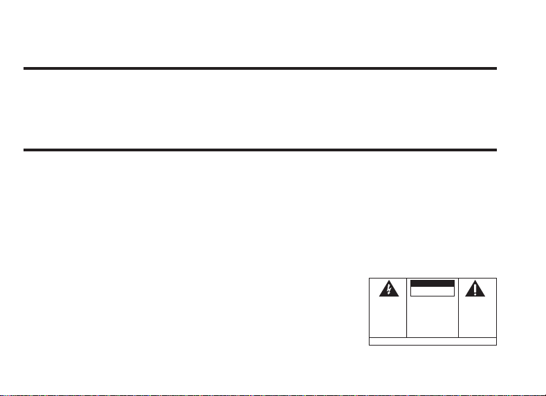
CAUTION
RISK OF ELECTRIC SHOCK
DO NOT OPEN
THE LIGHTNING
CAUTION: TO REDUCE THE
FLASH AND ARROW-
RISK OF ELECTRIC SHOCK,
HEAD WITHIN THE
DO NOT REMOVE COVER
TRIANGLE IS A
(OR BACK). NO USER-
WARNING SIGN
SERVICEABLE PARTS IN-
ALERTING YOU OF
WARNING:
OR ELECTRICAL SHOCK HAZARD,
DO NOT EXPOSE THIS PRODUCT
TO RAIN OR MOISTURE.
TO PREVENT FIRE
SIDE. REFER SERVICING
"DANGEROUS
TO QUALIFIED SERVICE
VOLTAGE" INSIDE
PERSONNEL.
THE PRODUCT.
SEE MARKING ON BOTTOM / BACK OF PRODUCT
THE EXCLAMATION
POINT WITHIN THE
TRIANGLE IS A
WARNING SIGN
ALERTING YOU OF
IMPORTANT
INSTRUCTIONS
ACCOMPANYING
THE PRODUCT.
Page 3
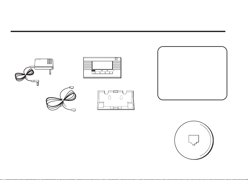
BEFORE YOU BEGIN
PARTS CHECKLIST
Make sure your package includes the following items:
DELETE
DISPLAYREVIEW
VIP
AC power supply
Caller ID unit
VERY IMPORTANT:
The Caller ID feature of
this product requires a
subscription to Caller ID
service from your
telephone company.
Telephone line cord
Mounting Bracket
MODULAR JACK REQUIREMENTS
You need an RJ11 type modular jack, which is the most
common type of phone jack and might look like the one
pictured here. If you don’t have a modular jack, call your local
phone company to find out how to get one installed.
1
Page 4
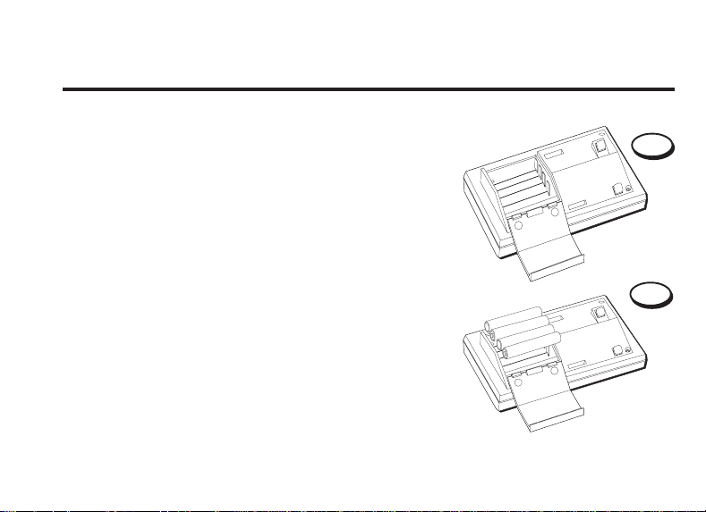
POWERING THE CALLER ID UNIT
The unit can operate on batteries only, but you must
use the AC power supply in order for the new call
indicator light and the display backlighting to work.
INSTALLING THE BATTERIES
Install 4 AAA-size batteries to retain caller ID information in the event of a power failure.
Disconnect the line cords from the back of the unit
and wait a few seconds for the unit to go into
standby.
1. Open the battery compartment door by pressing
on the door and sliding it in the direction of the
arrow.
2. Insert 4 AAA-size batteries as shown on the
diagram in the battery compartment.
3. Replace the battery compartment door securely.
2
1
2
Page 5

BATTERY INDICATOR
If the battery icon appears in the display, you need to
replace the batteries.
USING THE AC ADAPTER
You must use the AC power supply in order for the
new call indicator light and the display backlight to
work. When using AC power, the batteries serve as a
backup in the event of power failure.
NOTE: Only use the
Thomson 5-2408 AC
adapter that came with
this unit. Using other
adapters may damage
the unit.
3
Page 6

INSTALLATION
You can set the unit on a tabletop or mount it on the wall.
IMPORTANT INSTALLATION INFORMATION
• Never install telephone wiring during a lightning
storm.
• Never touch uninsulated telephone wires or
terminals, unless the telephone line has been
disconnected at the network interface.
• Use caution when installing or modifying telephone lines.
4
Page 7
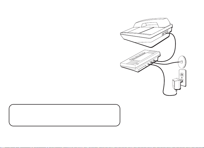
TABLETOP INSTALLATION
1. Connect the telephone line cord to the jack on the
back of the unit marked TO LINE, and to the
modular wall jack.
2. Connect your phone’s line cord to the jack on the
back of the unit marked TO PHONE.
3. Insert the AC adapter into the jack marked 9 V DC
into the back of the unit and to an AC power
outlet.
If you want the unit to sit up at an angle instead of
laying flat, attach the mounting bracket to the back of
the unit before connecting the cords.
NOTE: Only use the Thomson 5-2408 AC adapter
that came with this unit. Using other adapters may
damage the unit.
5
Page 8
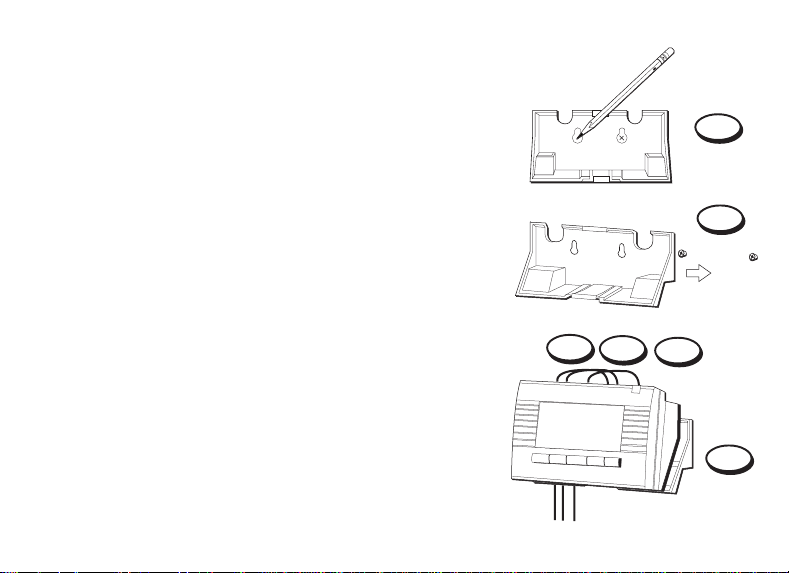
WALL MOUNT INSTALLATION
Use the mounting accessories included with this unit.
1. Hold the mounting bracket against the wall and
mark the mounting screw positions on the wall
with a pencil.
2. Insert the anchor screws and install the mounting
bracket on the wall.
3. Connect the telephone line cord to the jack on the
back of the unit marked TO LINE, and to the
modular wall jack.
4. Connect your phone’s line cord to the jack on the
back of the unit marked TO PHONE.
5. Insert the AC adapter into the jack marked 9 V DC
into the back of the unit and to an AC power
outlet.
6. Securely mount the unit on the bracket.
6
HB
Canestrare Graphics
1
2
3
4
5
6
Page 9

ANSWERING MACHINE INSTALLATION
The answering machine must be set to answer
calls after at least 2 rings to properly receive caller
ID information. To use your caller ID unit with an
answering machine:
1. Plug a telephone line cord into the modular
jack and into the jack on the back of the unit
marked TO LINE.
2. Plug another telephone line cord into the jack
on the back of the unit marked TO PHONE and
into the answering machine.
3. Plug a third telephone line cord into the
answering machine and into the phone.
4. Insert the AC adapter into the jack marked 9 V
DC into the back of the unit and to an AC
power outlet.
7
Page 10

TWO-LINE SYSTEM INSTALLATION
You must use two caller ID units if you
want to use caller ID for both lines. You
must also purchase a triplex adapter.
1. Plug the triplex adapter into your twoline modular wall jack.
2. Plug your two-line phone into the
two-line receptacle on the triplex
adapter.
3. Plug each caller ID unit into a singleline receptacle on the triplex adapter.
4. Connect the AC power supply for
each unit.
8
Page 11

OPERATION
CHOOSING A LANGUAGE
Your caller ID unit is programmed at the factory to display messages in English, but you
can change the language setting to French or Spanish. To change the language:
1. Press and hold DISPLAY until the current language (
Spanish, or
2. Press the REVIEW buttons until the language you want appears in the display.
3. When you release the REVIEW button the new language is set.
NOTE: If you don't press any buttons within 10 seconds the unit will go to TIME CALENDAR.
FRANCAIS
for French) appears in the display.
TIME AND DATE SETTINGS
The time and date are automatically set when your caller ID unit receives its first call.
This information is sent by the phone company.
ENGLISH, ESPANOL
for
9
Page 12

RECEIVING AND STORING CALLS
The display automatically lights when there is a new call
and whenever you press any of the buttons on the unit.
This unit receives and displays information transmitted
by your local phone company. This information can
include the phone number, date, and time; or the name,
phone number, date, and time. The new call indicator
flashes when there are new calls for you to review.
The unit can store up to 79 calls. When the memory is
full, a new call automatically replaces the oldest call in
memory. If there is a previous record with the same
information as the incoming call
display.
NOTE: Check with your local phone company
regarding name service availability.
NOTE: You must use the AC power supply in order
for the display's backlighting to work.
10
REPT
appears in the
New call indicator
SMITH JOHN
1-315-555-1324
AM
12:30
10/19
DELETE
VIP
The display
DISPLAYREVIEW
Page 13

DELETE AND REVIEW BUTTONS
DELETE BUTTON
• To delete THE record shown in the display, press
the DELETE button.
• To delete ALL records, press and hold the DELETE
button until
Press and release the DELETE button.
REVIEW BUTTONS
• Press REVIEW to see the next record. When all
messages have been viewed,
in the display.
• Press REVIEW to view previous records.
To REVIEW records faster: press and hold
REVIEW or REVIEW .
DELETE ALL?
appears in the display.
END OF LIST
appears
12:30
DELETE
DELETE
button
button
SMITH JOHN
1-315-555-1324
AM
10/19
VIP
REVIEW
button
REVIEW
DISPLAYREVIEW
11
Page 14

VERY IMPORTANT PERSON BUTTON
Use VIP memory for numbers you want to save. You
can store up to 20 names and numbers. To save a
number into VIP memory:
1. Press the REVIEW buttons until you reach
the desired number.
2. Press and hold VIP button. VIP icon (in the lower
right corner of the display) blinks and then
RECORD STORED
number is now stored in VIP memory.
To retrieve number from VIP memory:
1. Press VIP button. VIP icon appears in the display.
2. Press the
desired name and number.
12
appears in the display. The
REVIEW buttons to reach the
SMITH JOHN
1-315-555-1324
AM
12:30
10/19
DELETE
VIP
VIP button
DISPLAYREVIEW
Page 15

DELETE VIP NUMBERS
1. Press VIP to enter VIP memory.
2. Press the REVIEW buttons until you reach
the desired VIP number you to delete.
3. Press DELETE.
To delete all VIP records in memory:
1. Press VIP to enter VIP memory.
2. Press and hold DELETE until
DELETE ALL
appears in
the display.
3. Press and release DELETE to erase all VIP records.
DISPLAY CONTRAST ADJUSTMENT
To adjust the display's contrast:
• Press and release DISPLAY button until the
desired contrast is reached.
NOTE: To scroll through the contrast settings,
press the DISPLAY button.
SMITH JOHN
1-315-555-1324
AM
12:30
10/19
DELETE
VIP
DISPLAY button
DISPLAYREVIEW
13
Page 16

MESSAGE INDICATORS
The following messages tell you what your unit is doing.
BATTERY icon
BLOCKED NAME
BLOCKED NUMBER
BLOCKED CALL
DELETE ALL?
END OF LIST
LONG DISTANCE
NEW CALLS
14
Battery power level is low.
Caller ID information is withheld.
Delete all numbers from memory.
There are no additional calls to review.
Call is long distance
The unit has received incoming calls that have not been re-
viewed.
Page 17

no CALL
NO DATA SENT
RECORD STORED
REPT icon
SERVICE ERROR
UNKNOWN CALLER
VIP MEMO FULL
VIP Icon
The caller ID memory is empty.
The incoming call does not have caller ID service or their service
area is not linked to yours.
The caller ID record is stored in VIP memory.
Information is already stored in memory.
Caller information was interrupted during transmission.
Caller ID information incomplete.
No new VIP numbers can be entered.
VIP memory is active.
15
Page 18

TROUBLESHOOTING TIPS
NO DIAL TONE ON THE PHONE ATTACHED TO THE CALLER ID UNIT
• Check all cabling to make sure that all connections are secure.
• Check installation (p. 3-8)
• Disconnect the caller ID unit and reconnect phone to find out if the phone works
without the caller ID unit.
NO DISPLAY
• Replace batteries.
• Did you order caller ID service from your local telephone company? This unit
requires that you subscribe to caller ID service in order for it to work.
ERROR MESSAGE IS DISPLAYED
•
SERVICE ERROR
caller ID information during the silent period after the first ring. This message
indicates that there is noise on the line or that the telephone company has sent an
invalid message.
16
appears in the display if the unit detects anything other than valid
Page 19

GENERAL PRODUCT CARE
To keep your Caller ID working and looking good, follow these guidelines:
• Avoid putting it near heating appliances and devices that generate electrical noise (for
example, motors or fluorescent lamps).
• DO NOT expose to direct sunlight or moisture.
• Avoid dropping unit and/or other rough treatment.
• Clean with a soft cloth.
• Never use a strong cleaning agent or abrasive powder because this will damage the finish.
• Retain the original packaging in case you need to ship it at a later date.
17
Page 20

SERVICE
FCC requires this product to be serviced only by the manufacturer or its authorized
service agents. In accordance with FCC requirements, changes or modifications not
expressly approved by Thomson Consumer Electronics could void the user's authority
to operate the product. For instructions on how to obtain service, call Consumer
Information, 1-800-448-0329.
Attach your sales receipt to the booklet for future reference or jot down the date this
product was purchased or received as a gift. This information will be valuable if service
should be required during the warranty period.
Purchase date _________________________ Name of store ________________________
18
Page 21

FCC REGISTRATION INFORMATION
Your GE telephone equipment is registered with the Federal Communications Commission and is in compliance with
parts 15 and 68, FCC Rules and Regulations.
1 Notification to the Local Telephone Company
On the bottom of this equipment is a label indicating, among other information, the FCC Registration number and
Ringer Equivalence Number (REN) for the equipment. You must, upon request, provide this information to your
telephone company.
The REN is useful in determining the number of devices you may connect to your telephone line and still have all
of these devices ring when your telephone number is called. In most (but not all) areas, the sum of the RENs of all
devices connected to one line should not exceed 5. To be certain of the number of devices you may connect to your
line as determined by the REN, you should contact your local telephone company.
Notes
• This equipment may not be used on coin service provided by the telephone company.
• Party lines are subject to state tariffs, and therefore, you may not be able to use your own telephone equipment
if you are on a party line. Check with your local telephone company.
• Notice must be given to the telephone company upon permanent disconnection of your telephone from your
line.
2 Rights of the Telephone Company
Should your equipment cause trouble on your line which may harm the telephone network, the telephone
company shall, where practicable, notify you that temporary discontinuance of service may be required. Where
prior notice is not practicable and the circumstances warrant such action, the telephone company may
temporarily discontinue service immediately. In case of such temporary discontinuance, the telephone company
must: (1) promptly notify you of such temporary discontinuance; (2) afford you the opportunity to correct the
situation; and (3) inform you of your right to bring a complaint to the Commission pursuant to procedures set
forth in Subpart E of Part 68, FCC Rules and Regulations.
The telephone company may make changes in its communications facilities, equipment, operations of
procedures where such action is required in the operation of its business and not inconsistent with FCC Rules and
Regulations. If these changes are expected to affect the use or performance of your telephone equipment, the
telephone company must give you adequate notice, in writing, to allow you to maintain uninterrupted service.
19
Page 22

INTERFERENCE INFORMATION
This device complies with Part 15 of the FCC Rules. Operation is subject to the following two conditions: (1) This
device may not cause harmful interference; and (2) This device must accept any interference received, including
interference that may cause undesired operation.
This equipment has been tested and found to comply with the limits for a Class B digital device, pursuant to Part 15
of the FCC Rules. These limits are designed to provide reasonable protection against harmful interference in a
residential installation.
This equipment generates, uses, and can radiate radio frequency energy and, if not installed and used in
accordance with the instructions, may cause harmful interference to radio communications. However, there is no
guarantee that interference will not occur in a particular installation.
If this equipment does cause harmful interference to radio or television reception, which can be determined by
turning the equipment off and on, the user is encouraged to try to correct the interference by one or more of the
following measures:
• Reorient or relocate the receiving antenna (that is, the antenna for radio or television that is “receiving” the
interference).
• Reorient or relocate and increase the separation between the telecommunications equipment and receiving
antenna.
• Connect the telecommunications equipment into an outlet on a circuit different from that to which the receiving
antenna is connected.
• Consult the dealer or an experienced radio/TV technician for help.
If these measures do not eliminate the interference, please consult your dealer or an experienced radio/
television technician for additional suggestions. Also, the Federal Communications Commission has prepared a
helpful booklet, “How To Identify and Resolve Radio/TV Interference Problems.” This booklet is available from
the U.S. Government Printing Office, Washington, D.C. 20402. Please specify stock number 004-000-00345-4
when ordering copies.
FCC NUMBER IS LOCATED ON THE CABINET BOTTOM
REN NUMBER IS LOCATED ON THE CABINET BOTTOM
20
Page 23

LIMITED WARRANTY
What your warranty covers:
• Any defect in materials or workmanship.
For how long after your purchase:
• One year.
(The warranty period for rental units begins with the first rental
or 45 days from date of shipment to the rental firm, whichever
comes first.)
What we will do:
• Provide you with a new, or at our option, a refurbished unit.
• The exchange unit is under warranty for the remainder of
the original product’s warranty period.
How to make a warranty claim:
• Properly pack your unit. Include any cables, etc., which
were originally provided with the product. We recommend
using the original carton and packing materials.
• Include in the package evidence of purchase date such as
the bill of sale. Also print your name and address and a
description of the defect. Send standard UPS or its
equivalent to:
Thomson Consumer Electronics, Inc.
Product Exchange Center
32 Spur Drive
El Paso, Texas 79906
• Pay any charges billed to you by the Exchange Center for
service not covered by the warranty.
• A new or refurbished unit will be shipped to you prepaid
freight.
What your warranty
• Customer instruction. (Your Owner’ s Manual pro vides
information regarding operating instructions and user
controls. For additional information, ask your dealer.)
• Installation and set-up service adjustments.
• Batteries.
• Damage from misuse or neglect.
• Products which have been modified or incorporated into
other products.
• Products purchased or serviced outside the USA.
• Acts of God, such as but not limited to lightning damage.
Product Registration:
• Please complete and mail the Product Registration Card
packed with your unit. It will make it easier to contact you
should it ever be necessary. The return of the card is not
required for warranty coverage.
How state law relates to this warranty:
• This warranty gives you specific legal rights, and you may
have other rights which vary from state to state.
If you purchased your product outside the USA:
• This warranty does not apply. Contact your dealer for
warranty information.
does not
cover:
21
Page 24

Model 2-9079
347A8359-0001 (Rev. 0 E/S)
96-30
Printed in Hong Kong
P.O. Box 1976, Indianapolis, IN 46206
© 1996 Thomson Consumer Electronics, Inc.
Trademark(s) ® Registered
Marca(s) ® Registrada(s)
 Loading...