

Page 1
SAFETY PRECASAFETY PRECA
SAFETY PRECA
SAFETY PRECASAFETY PRECA
SERSER
VICE VICE
SER
SERSER
Only qualified service technicians who are familiar with safety checks
and guidelines should perform service work. Before replacing parts,
disconnect power source to protect electrostatically sensitive parts. Do
not attempt to modify any circuit unless so recommended by the
manufacturer. When servicing the receiver, use an isolation transformer
between the line cord and power receptacle.
SERSER
SER
SERSER
Use EXTREME CAUTION when servicing the high voltage circuits. To
discharge static high voltage, connect a 10K ohms resistor in series with a
test lead between the receiver ground and CRT anode lead. DO NOT lift
the CRT by the neck. Always wear shatterproof goggles when handling
the CRT to protect eyes in case of implosion.
X-RAX-RA
X-RA
X-RAX-RA
Be aware of the instructions and procedures covering X-ray radiation. In
solid-state receivers and monitors, the CRT is the only potential source of
X-rays. Keep an accurate high voltage meter available at all times. Check
meter calibration periodically. Whenever servicing a receiver, check the
high voltage at various brightness levels to be sure it is regulating
properly. Keep high voltage at rated value, NO HIGHER. Excessive high
voltage may cause X-ray radiation or failure of associated components.
DO NOT depend on protection circuits to keep voltage at rated value.
When troubleshooting a receiver with excessive high voltage, avoid close
contact with the CRT. DO NOT operate the receiver longer than
necessary. To locate the cause of excessive high voltage, use a variable
AC transformer to regulate voltage. In present receivers, many electrical
and mechanical components have safety related characteristics which are
not detectable by visual inspection. Such components are identified by a
# on both the schematic and the parts list. For SAFETY, use only
equivalent replacement parts when replacing these components.
GENERAL GUIDELINESGENERAL GUIDELINES
GENERAL GUIDELINES
GENERAL GUIDELINESGENERAL GUIDELINES
Perform a final SAFETY CHECK before returning receiver to customer.
Check repaired area for poorly soldered connections, and check entire
circuit board for solder splashes. Check board wiring for pinched wires or
wires contacting any high wattage resistors. Check that all control knobs,
shields, covers, grounds, and mounting hardware have been replaced. Be
sure to replace all insulators and restore proper lead dress.
WARNINGWARNING
VICE
WARNING
VICE VICE
WARNINGWARNING
VICING VICING
VICING
VICING VICING
Y RADIAY RADIA
Y RADIA
Y RADIAY RADIA
THE HIGH THE HIGH
THE HIGH
THE HIGH THE HIGH
TION AND HIGH TION AND HIGH
TION AND HIGH
TION AND HIGH TION AND HIGH
VV
OLOL
V
OL
VV
OLOL
TT
AA
GE AND CRGE AND CR
T
A
GE AND CR
TT
AA
GE AND CRGE AND CR
VV
OLOL
TT
V
OL
T
VV
OLOL
TT
TT
T
TT
AA
GE LIMITSGE LIMITS
A
GE LIMITS
AA
GE LIMITSGE LIMITS
UTIONSUTIONS
UTIONS
UTIONSUTIONS
SAFETY CHECKS — FIRE AND SHOCK HAZARDSAFETY CHECKS — FIRE AND SHOCK HAZARD
SAFETY CHECKS — FIRE AND SHOCK HAZARD
SAFETY CHECKS — FIRE AND SHOCK HAZARDSAFETY CHECKS — FIRE AND SHOCK HAZARD
Cold LeakaCold Leaka
Cold Leaka
Cold LeakaCold Leaka
Unplug the AC cord, connect a jumper across the plug prongs, and turn
the power switch on (if applicable). Use an ohmmeter to measure the
resistance between the jumped AC plug and any exposed metal cabinet
parts such as antenna screw heads, control shafts, or handle brackets.
Exposed metal parts with a return path should measure between 1M
ohms and 5.2M ohms. Parts without a return path must measure infinity.
Hot LeakaHot Leaka
Hot Leaka
Hot LeakaHot Leaka
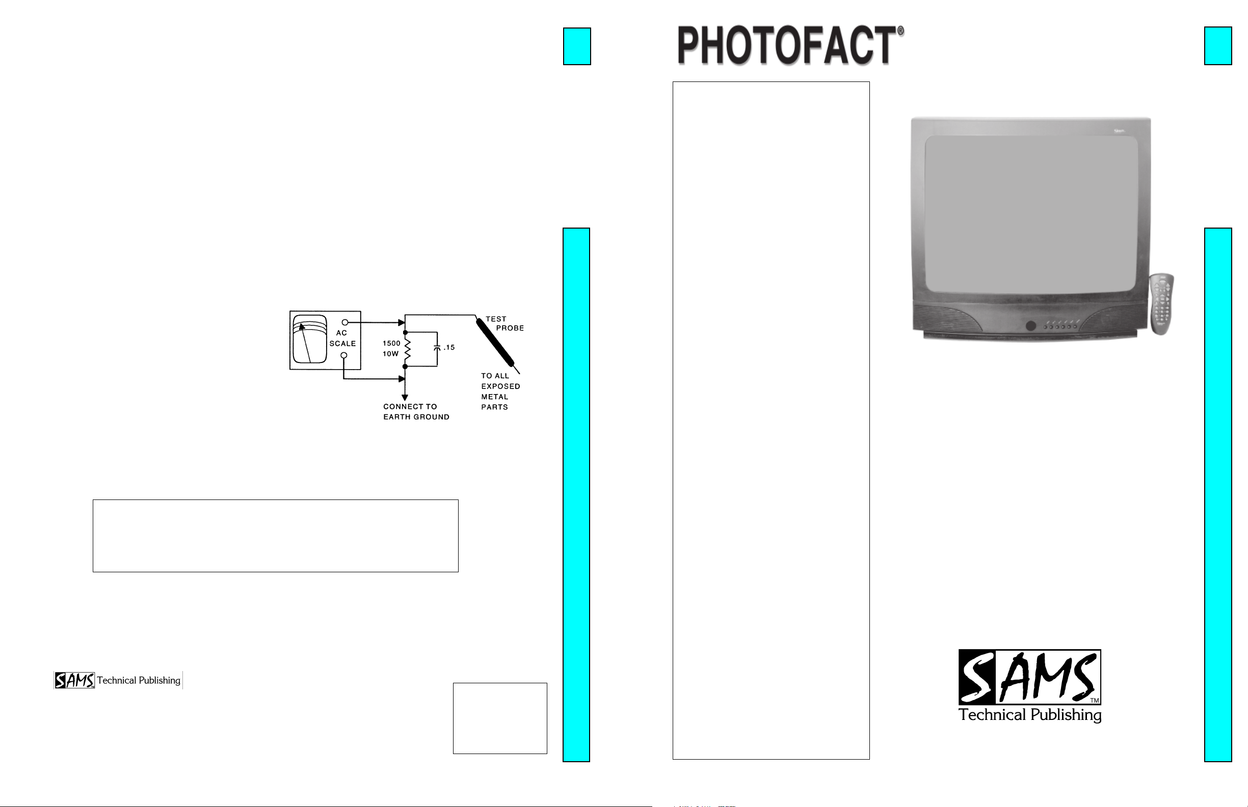
Plug the AC cord directly into an AC outlet. DO NOT use an isolation
transformer. Use a 1500 ohms, 10W resistor in parallel with a .15µF
capacitor to connect between any exposed metal parts on the receiver and
a good earth ground. (See figure below.) Use an AC voltmeter with at
least 5000 ohms per volt sensitivity to measure the voltage across the
resistor. Check all exposed metal parts and measure voltage at each point.
Voltage measurements should not exceed .75VAC, 500µA. Any value
exceeding this limit constitutes a potential shock hazard and must be
corrected. If the AC plug is not polarized, reverse the AC plug and repeat
exposed metal part voltage measurement at each point.
gg
e Chece Chec
e Chec
e Chece Chec
ks fks f
ks f
ks fks f
g
gg
gg
e Current Chece Current Chec
g
e Current Chec
gg
e Current Chece Current Chec
or Receiveror Receiver
or Receiver
or Receiveror Receiver
kk
k
kk
s with Isolated Grs with Isolated Gr
s with Isolated Gr
s with Isolated Grs with Isolated Gr
oundound
ound
oundound
4715
SET 4715SET 4715
SET 4715SET 4715
SET 4715
Y1/Y7)Y1/Y7)
Y1/Y7)Y1/Y7)
Y1/Y7)
Error Codes Chart .................................. 1
GridTrace Location
High Voltage Shutdown Test .................. 1
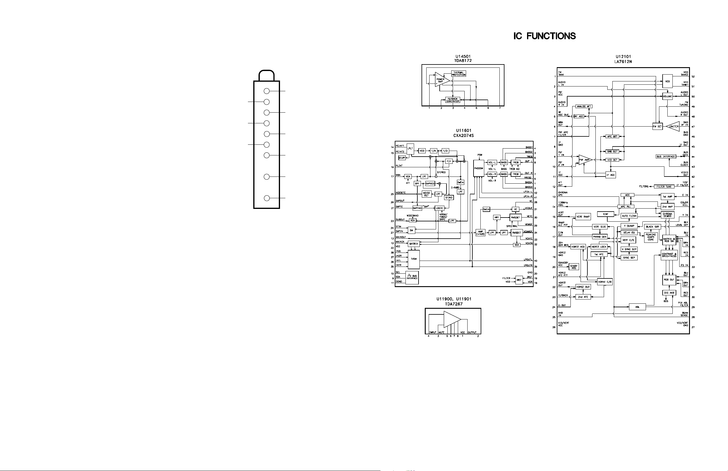
IC Functions ........................................... 1
Important Parts Information ................... 2
Miscellaneous Adjustments .................... 1
Parts List ................................................. 4
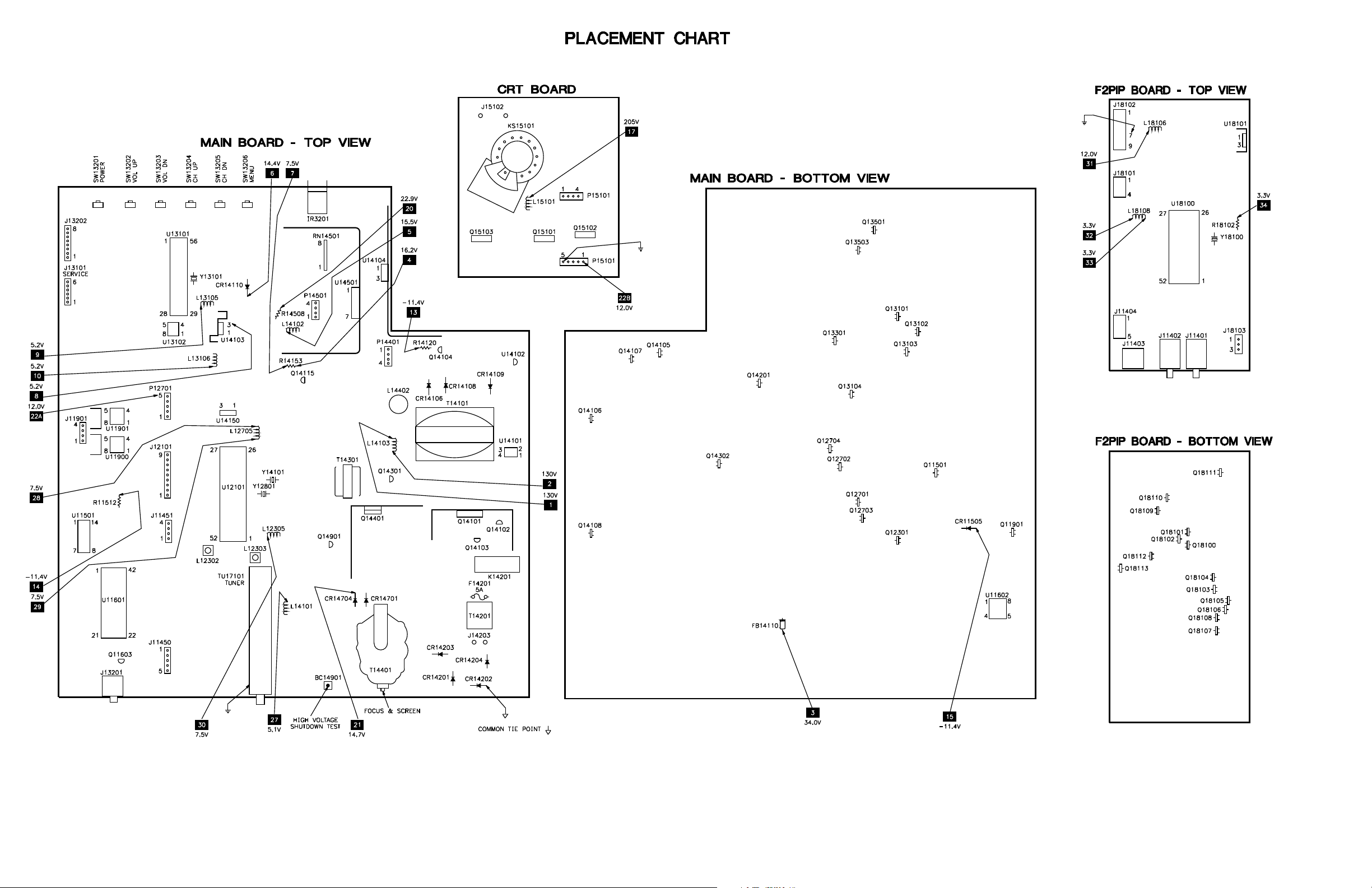
Placement Chart ..................................... 1
Safety Precautions .................................. 1
Schematic Component Location ............ 3
Schematic Notes ..................................... 2
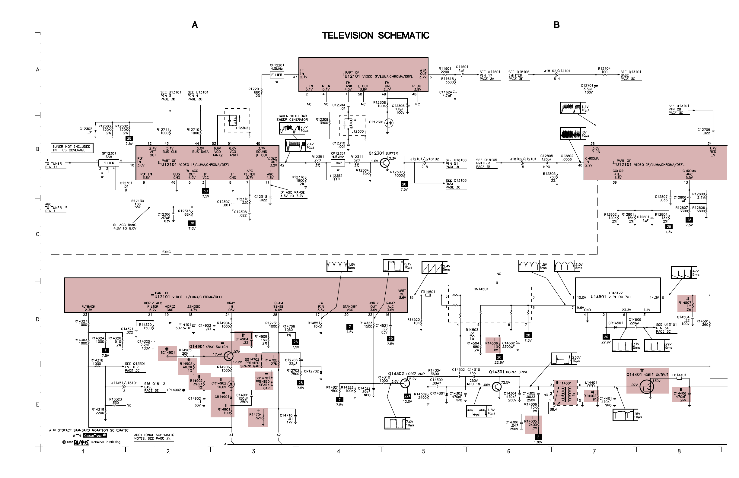
Schematics
Test Equipment....................................... 2
Tuner Information .................................. 1
INDEXINDEX
INDEX
INDEXINDEX
Main Board ..................................... 4
Audio ............................................... 3
PIP ................................................... 3
Power Supply .................................. 2
System Control ................................ 3
Television ........................................ 2
Technical Service Data
GEGE
GE
GEGE
Model 27GT716YX1 (Chassis CTC203AModel 27GT716YX1 (Chassis CTC203A
Model 27GT716YX1 (Chassis CTC203A
Model 27GT716YX1 (Chassis CTC203AModel 27GT716YX1 (Chassis CTC203A
Representative Model
ff
or seror ser
f
or ser
ff
or seror ser
Essential coEssential co
Essential co
Essential coEssential co
vicing a televicing a tele
vicing a tele
vicing a televicing a tele
ScSc
hematicshematics
•
Sc
hematics
ScSc
hematicshematics
veravera
gg
vera
veravera
vision receivervision receiver
vision receiver
vision receivervision receiver
ee
g
e
gg
ee
Y1/Y7)Y1/Y7)
Y1/Y7)
Y1/Y7)Y1/Y7)
......
...
......
4715
4715
HIGH HIGH
VV
OLOL
TT
AA
HIGH
V
HIGH HIGH
VV
Momentarily short BC14901 (see Q14901 base) to ground. The receiver should lose raster and sound. If
receiver does not lose raster and sound, the shutdown circuit should be repaired. To resume normal
operation, remove AC power for approximately 30 seconds and then turn the receiver on.
The listing of any available replacement part herein in no case constitutes a recommendation, warranty, or guarantee by
SAMS Technical Publishing as to the quality and suitability of such replacement part. The numbers of the listed parts have
been compiled from information furnished to SAMS Technical Publishing by the manufacturers of the specific type of
replacement part listed.
Reproduction or use, without express permission, of editorial or pictorial content, in any manner, is prohibited. No patent
liability is assumed with respect to the use of the information contained herein.
© 2003
5436 West 78th Street
Indianapolis, IN 46268-4149
Printed in the United States of America 5 4 3 2 1
PP
aa
gg
e 1e 1
a
g
e 1
aa
gg
e 1e 1
SET 4715 SET 4715
SET 4715
SET 4715 SET 4715
P
PP
GE SHUTDOGE SHUTDO
OL
T
A
GE SHUTDO
OLOL
TT
AA
GE SHUTDOGE SHUTDO
WN WN
TESTTEST
WN
TEST
WN WN
TESTTEST
03PF02087
UPC
HERE
MODEL 27GT716YX1 (CHASSIS CTC203AMODEL 27GT716YX1 (CHASSIS CTC203A
MODEL 27GT716YX1 (CHASSIS CTC203AMODEL 27GT716YX1 (CHASSIS CTC203A
MODEL 27GT716YX1 (CHASSIS CTC203A
GEGE
GEGE
GE
For Supplier AdFor Supplier Ad
For Supplier Ad
For Supplier AdFor Supplier Ad
See PHOSee PHO
See PHO
See PHOSee PHO
TT
T
TT
OFOF
OF
OFOF
AA
CT AnnCT Ann
A
CT Ann
AA
CT AnnCT Ann
dress,dress,
dress,
dress,dress,
ual Indeual Inde
ual Inde
ual Indeual Inde
xx
x
xx
Component locationsComponent locations
•
Component locations
Component locationsComponent locations
PP
arar
ts listts list
•
P
ar
ts list
PP
arar
ts listts list
APRIL APRIL
APRIL
APRIL APRIL
2003 SET 4715 2003 SET 4715
2003 SET 4715
2003 SET 4715 2003 SET 4715
Page 2
PP
aa
gg
e 1e 1
g
e 1
gg
e 1e 1
SET 4715 SET 4715
SET 4715
SET 4715 SET 4715
P
a
PP
aa
TUNER INFORMATION
TUNER TUNER
TUNER
TUNER TUNER
PinPin
Pin
PinPin
(1) AGC 2.4V 2.3V 2.8V
(2) TU 1.3V 4.2V 5.5V
(3) +5V 5.1V 5.1V 5.1V
(4) CLK 5.1V 5.1V 5.1V
(5) DATA 5.1V 5.1V 5.1V
(6) +5V 5.1V 5.1V 5.1V
(7) +5V 5.1V 5.1V 5.1V
(9) +32V 34.0V 34.0V 34.0V
(11) IF 0V 0V 0V
NOTE: VHF Low Band voltages taken on channel 2.
VHF LoVHF Lo
VHF Lo
VHF LoVHF Lo
VHF High Band voltages taken on channel 7.
UHF Band voltages taken on channel 14
w Bandw Band
w Band
w Bandw Band
VV
OLOL
TT
V
OL
T
VV
OLOL
TT
AA
GE CHARGE CHAR
A
GE CHAR
AA
GE CHARGE CHAR
VHF High BandVHF High Band
VHF High Band
VHF High BandVHF High Band
TT
T
TT
UHF BandUHF Band
UHF Band
UHF BandUHF Band
TUNER TUNER
TUNER
TUNER TUNER
(2)
(4)
(6)
TERMINAL GUIDETERMINAL GUIDE
TERMINAL GUIDE
TERMINAL GUIDETERMINAL GUIDE
(1)
τ
τ
(3)
τ
τ
(5)
τ
τ
(7)
τ
(9)
τ
(11)
τ
Page 3

SET 4715 PSET 4715 P
SET 4715 P
SET 4715 PSET 4715 P
aa
gg
e 1e 1
a
g
e 1
aa
gg
e 1e 1
MISCELLANEOUS ADJUSTMENTS
NOTE: All procedures require an antenna connected and power applied to
the set.
HIGH HIGH
VV
OLOL
TT
AA
HIGH
V
HIGH HIGH
VV
Tune in a picture. Set brightness, contrast, and color to minimum. Connect
a high voltage probe to the CRT anode. High voltage should be 27kV to
29kV.
SERSER
VICE MENUVICE MENU
SER
VICE MENU
SERSER
VICE MENUVICE MENU
The following adjustment procedures are accessed thru a service menu. To access the service menu, turn the receiver on, press the menu button and hold it
down while pressing the power button. While holding down the menu button, release the power button and press the volume + button. The screen will
display a one line menu, on the left the parameter P0, and on the right the value of that parameter V0. Release buttons. Adjustments are made by selecting
the proper parameter and changing the value of that parameter. To change the parameter number use channel up and down buttons. To adjust the current
value of that parameter use volume + and - buttons. To access and change any of the adjustments, the proper parameter pass number must be entered. This
information is listed at the beginning of the alignment. When these parameters are modified, the T-Chip and the corresponding EEPROM are updated. All
service adjustments are bus controlled, except focus and screen.
NOTE: In order to adjust the RF AGC, audio or video levels, tuner, PIP, or stereo circuits, the Chipper Check hardware and software must be used. This
can be purchased from Thomson Electronics. Before making any changes to any of the values, record the On-Set values.
VICE ADJUSTMENT PARAMETERSVICE ADJUSTMENT PARAMETERS
SERSER
VICE ADJUSTMENT PARAMETERS
SER
VICE ADJUSTMENT PARAMETERSVICE ADJUSTMENT PARAMETERS
SERSER
PP
arameterarameter
P
arameter
PP
arameterarameter
No.No.
No.
No.No.
0 Pass number for service Must set to 76 - May not advance until value is set to 76.
1 Error Code 1 0 0 - 255 Displays the first error detected. Set to 0 before exiting.
2 Error Code 2 0 0 - 255 Displays the second error detected. Set to 0 before exiting.
3 Error Code 3 0 0 - 255 Displays the last error detected. Set to 0 before exiting.
4 Horizontal Phase 10 0 - 15 Tune in a crosshatch pattern, adjust to center the pattern
5 EW DC (Width) 16 0 - 31 Tune in a crosshatch pattern, adjust for slight horizontal
6 EW Amplitude 8 0 - 15 Set value to 8.
7 EW Tilt 8 0 - 15 Set value to 8.
8 Top Corner Pin Correction 2 0 - 7 Set value to 2.
9 Bottom Corner Pin Correction 2 0 - 7 Set value to 2.
10 Vertical DC 33 0 - 63 Tune in a crosshatch pattern, adjust to center vertically.
11 Vertical Size 84 0 - 127 Tune in a crosshatch pattern, adjust for slight vertical overscan.
12 Vertical Countdown Mode 0 0 - 3 Set value to 0. (0 = Standard, 1 = Non-Standard, 2 = 50Hz,
13 Red Bias 30 0 - 127 Press menu button on the TV set for setup line.
14 Green Bias 15 0 - 127 Press menu button on the TV set for setup line.
15 Blue Bias 34 0 - 127 Press menu button on the TV set for setup line.
16 Red Drive 41 0 - 63 17 Green Drive 33 0 - 63 18 Blue Drive 32 0 - 63 19 Gemstar Horizontal OSD Position 166 0 - 255 Set value to 166.
20 Gemstar Vertical OSD Position 68 0 - 255 Set value to 68.
21 Gemstar PIP Horizontal Position 40 0 - 255 Set value to 40.
22 Gemstar PIP Vertical Position 43 0 - 255 Set value to 43.
23 Gemstar PIP Window Vertical Size 3 0 - 13 Set value to 3.
OL
OLOL
T
A
TT
AA
PP
P
PP
GE CHECKGE CHECK
GE CHECK
GE CHECKGE CHECK
arameter Namearameter Name
arameter Name
arameter Namearameter Name
adjustment parameters.
On-SetOn-Set
On-Set
On-SetOn-Set
VV
aluealue
V
alue
VV
aluealue
COLOR COLOR
COLOR
COLOR COLOR
NOTE: See Service Adjustment Parameters to change drive and bias values.
Press menu button for collapsed raster service line. Disconnect the antenna.
Preset the red, green, and blue drive values to 32. Adjust screen control for
a service line that is just visible. Adjust red, green, and blue drives to obtain
a white raster. Check the low light to high light gray scale tracking. Repeat
the procedure, if necessary, to obtain the best performance.
VV
aluealue
V
alue
VV
aluealue
RangRang
ee
Rang
e
RangRang
ee
TEMPERATEMPERA
TEMPERA
TEMPERATEMPERA
CommentComment
Comment
CommentComment
See Error Codes Chart.
See Error Codes Chart.
See Error Codes Chart.
on the screen.
overscan.
3 = 48Hz)
TURETURE
TURE
TURETURE
ERROR CODES CHART
ErrErr
or Codeor Code
Err
or Code
ErrErr
or Codeor Code
DECDEC
HEXHEX
DEC
HEX
DECDEC
HEXHEX
0 00 No error code 1 01 16.0V fault 16.0V STBY source is failing.
3 03 12.0V run fault 12.0V source is failing.
4 04 T4 Chip Run supply failed.
8 08 T4 Chip X-ray protection caused high voltage shutdown.
9 09 T4 Chip (POR) Power supply problem at (POR) power on reset.
10 0A F2 PIP module error (POR) Power supply problem at (POR) power on reset/PIP.
11 0B Stereo decoder (POR) Power supply problem at reset/Stereo decoder.
16 10 Run IIC Bus held low Run IIC clock or data held low.
18 12 Standby IIC Bus held low Standby IIC clock or data held low.
23 17 Gemstar 4 Board Guide fatal error on set using Gemstar 4 Board.
24 18 Gemstar 4 Board Task monitor error on set using Gemstar 4 Board.
25 19 Gemstar 4 Board Watchdog error on set using Gemstar 4 Board.
34 22 Gemstar 4 Board Gemstar 4 fails to acknowledge.
44 2C F2PIP module error F2PIP fails to acknowledge.
102 66 Octal DAC Octal DAC fails to acknowledge.
128 80 Stereo decoder Stereo decoder fails to acknowledge.
160 A0 Main or PIP tuner EEPROM Main or PIP tuner EEPROM fails to acknowledge.
186 BA T4 Chip T4 Chip fails to acknowledge.
196 C4 Main tuner PLL/DAC Main tuner PLL IC fails to acknowledge.
198 C6 Main tuner PLL/DAC Main tuner DAC IC fails to acknowledge.
ERRERR
OR CODESOR CODES
ERR
OR CODES
ERRERR
OR CODESOR CODES
If certain failures occur, the matching error codes will be stored in the
EEPROM. These error codes will be displayed in parameters 1, 2, and 3.
The first failure error code will be stored at parameter 1 and the second
failure error code will be stored at parameter 2. Parameter 3 will be updated
to display the most recent failure occurred in the chassis. If a failure of a
bus IC occurred, the normal acknowledgment checking of that bus will be
disabled in the service mode and the address of that IC which failed will be
stored in one of the error code parameters. After every repair is done to the
chassis it is recommended to check the error code parameters and reset
them back to value 0.
ErrErr
or Locationor Location
Err
or Location
ErrErr
or Locationor Location
Condition IndicatedCondition Indicated
Condition Indicated
Condition IndicatedCondition Indicated
Page 4
GE MODEL 27GT716YX1 (CHASSIS CTC203A
GE MODEL 27GT716YX1 (CHASSIS CTC203AGE MODEL 27GT716YX1 (CHASSIS CTC203A
GE MODEL 27GT716YX1 (CHASSIS CTC203AGE MODEL 27GT716YX1 (CHASSIS CTC203A
Y1/Y7)
Y1/Y7)Y1/Y7)
Y1/Y7)Y1/Y7)
SET 4715 PSET 4715 P
SET 4715 P
SET 4715 PSET 4715 P
aa
gg
e 1e 1
a
g
e 1
aa
gg
e 1e 1
Page 5
PP
aa
gg
e 2e 2
g
gg
e 2
e 2e 2
SET 4715 SET 4715
SET 4715
SET 4715 SET 4715
P
a
PP
aa
Page 6

SET 4715 PSET 4715 P
SET 4715 P
SET 4715 PSET 4715 P
aa
gg
e 2e 2
a
g
e 2
aa
gg
e 2e 2
Page 7

PP
aa
gg
e 2e 2
a
g
e 2
aa
gg
e 2e 2
SET 4715 SET 4715
SET 4715
SET 4715 SET 4715
P
PP
Page 8

ImporImpor
tant Ptant P
arar
ts Infts Inf
Impor
tant P
ImporImpor
ν The parts listed here are those not usually available from a well-stocked supply cabinet or bin.
ν Where items may be replaced with equivalent parts, several alternates are shown from participating vendors.
ν On the parts lists, safety items are marked with a
these items.
ν When ordering parts, state the model number, part number, and description.
ar
tant Ptant P
arar
# #
# to remind you that only exact replacements are recommended for
# #
ts Inf
ts Infts Inf
ormationormation
ormation
ormationormation
Obtaining PObtaining P
Obtaining P
Obtaining PObtaining P
Many of these parts are available from your local Sams authorized distributor or the manufacturer of the equipment. Call
Sams for the name of your nearest distributor:
arar
ar
arar
tsts
ts
tsts
800-428-7267
Or consult the Sams
Information on test equipment and replacement parts is listed in these pages for the following participating vendors.
Consult the Sams
ν NTE Electronics, Inc. (NTE)
Test equipment listed by participating manufacturer illustrates typical or equivalent equipment used by Sams engineers to obtain
measurements. This equipment is compatible with most types used by field service technicians.
Annual Index
Annual Index
for the address of the original equipment manufacturer.
PP
arar
ticipating ticipating
P
ar
ticipating
PP
arar
ticipating ticipating
for their current address.
TEST EQTEST EQ
TEST EQ
TEST EQTEST EQ
VV
endorendor
V
endor
VV
endorendor
ν Sencore, Inc.
UIPMENTUIPMENT
UIPMENT
UIPMENTUIPMENT
ss
s
ss
GE MODEL 27GT716YX1 (CHASSIS CTC203A
GE MODEL 27GT716YX1 (CHASSIS CTC203AGE MODEL 27GT716YX1 (CHASSIS CTC203A
GE MODEL 27GT716YX1 (CHASSIS CTC203AGE MODEL 27GT716YX1 (CHASSIS CTC203A
EquipmentEquipment
Equipment
EquipmentEquipment
Oscilloscope SC3100
Generators
RGB CM2125
Multiburst Signal VG91
Color Bar VG91
TV Stereo VG91
Digital VOM SC3100
Frequency Meter SC3100
Hi-Voltage Probe HP200
Accessory Probes TP212
Sencore No.Sencore No.
Sencore No.
Sencore No.Sencore No.
EquipmentEquipment
Equipment
EquipmentEquipment
Isolation Transformer PR570
Capacitance Analyzer LC102
CRT Analyzer CR7000
AC Leakage Tester PR570
Inductance Analyzer LC102
Flyback Yoke Tester TVA92
Field Strength Meter SL753
Transistor Tester TF46
Horizontal Analyzer HA-2500
Video Analyzer VG91, TVA92
Sencore No.Sencore No.
Sencore No.
Sencore No.Sencore No.
SET 4715 PSET 4715 P
SET 4715 P
SET 4715 PSET 4715 P
aa
gg
a
g
aa
gg
Y1/Y7)
Y1/Y7)Y1/Y7)
Y1/Y7)Y1/Y7)
e 2e 2
e 2
e 2e 2
Page 9

PP
aa
gg
e 3 SET 4715e 3 SET 4715
P
a
g
e 3 SET 4715
PP
aa
gg
e 3 SET 4715e 3 SET 4715
Page 10

SET 4715 PSET 4715 P
SET 4715 P
SET 4715 PSET 4715 P
aa
gg
e 3e 3
a
g
e 3
aa
gg
e 3e 3
Page 11

PP
aa
gg
e 3e 3
a
g
e 3
aa
gg
e 3e 3
SET 4715 SET 4715
SET 4715
SET 4715 SET 4715
SET 4715 PSET 4715 P
SET 4715 P
SET 4715 PSET 4715 P
aa
gg
e 3e 3
a
g
e 3
aa
gg
e 3e 3
P
PP
Page 12

SCHEMASCHEMA
SCHEMA
SCHEMASCHEMA
TIC COMPONENT LOCATIC COMPONENT LOCA
TIC COMPONENT LOCA
TIC COMPONENT LOCATIC COMPONENT LOCA
TION GUIDETION GUIDE
TION GUIDE
TION GUIDETION GUIDE
C11401 B46
C11402 C46
C11403 B46
C11450 B30
C11451 B30
C11453 C35
C11454 D35
C11455 C35
C11456 D35
C11501 D32
C11502 D32
C11503 D35
C11504 D35
C11506 D30
C11507 E30
C11601 A5
C11602 C30
C11603 C30
C11604 C32
C11605 D32
C11606 C32
C11607 C32
C11608 B30
C11609 B30
C11610 C30
C11611 B30
C11612 D30
C11613 D30
C11614 C30
C11615 C30
C11616 C29
C11617 A30
C11618 D30
C11619 A30
C11620 C32
C11621 B32
C11622 B32
C11623 D32
C11624 A5
C11625 D32
C11626 A31
C11627 A31
C11628 A33
C11629 B31
C11630 A33
C11631 A33
C11701 E29
C11702 D30
C11703 D30
C11704 E30
C11705 E30
C11906 A34
C11907 B34
C11908 C35
C11909 B35
C11910 A34
C11912 B34
C11913 A36
C11914 B36
C12301 C1
C12302 B1
C12303 D37
C12304 A4
C12305 A5
C12306 C2
C12307 C3
C12308 C3
C12310 B4
C12312 C28
C12313 C3
C12314 C28
C12701 A7
C12702 C10
C12703 C10
C12704 C9
C12706 D4
C12707 C28
C12708 C28
C12709 B8
C12710 B9
C12711 B11
C12712 A28
C12713 C10
C12714 C13
C12715 B13
C12716 B13
C12717 C9
C12718 C10
C12801 C8
C12802 B7
C12803 C9
C12805 B6
C12806 C8
C12807 C8
C13102 C37
C13103 C38
C13104 E39
C13105 C38
C13106 C41
C13107 D41
C13108 B38
C13109 C38
C13110 B38
C13111 B38
C13113 C24
C13114 D38
C13115 C24
C13119 B43
C13129 B41
C13141 D41
C13144 C41
C13163 B24
C13165 C24
C13169 B41
C13170 C40
C13201 A37
C13202 A37
C13301 A41
C13302 E41
C13312 E41
C13501 E40
C13502 E40
C13503 D40
C13504 D39
C14101 B19
C14102 B20
C14103 B19
C14104 C19
C14105 C19
C14106 C20
C14107 C20
C14108 A20
C14109 A22
C14110 A24
C14111 B23
C14112 B23
C14113 B21
C14114 B24
C14115 C21
C14116 D23
C14118 A28
C14119 B24
C14121 B24
C14122 A24
C14123 D21
C14124 A22
C14125 B20
C14126 C19
C14127 C20
C14150 C28
C14151 C26
C14152 B24
C14153 B24
C14154 B27
C14155 B28
C14158 B24
C14159 B23
C14160 B27
C14201 A17
C14203 A19
C14204 A19
C14205 A20
C14206 A20
C14207 B18
C14208 A17
C14302 E5
C14303 E5
C14304 E6
C14305 E6
C14306 E6
C14309 E5
C14310 E5
C14320 D2
C14321 D2
C14322 E4
C14401 E7
C14402 E9
C14403 D9
C14404 D9
C14405 D10
C14406 E8
C14502 D6
C14504 D8
C14505 D7
C14506 E21
C14507 E21
C14521 D5
C14701 E20
C14702 D19
C14703 D19
C14704 D19
C14706 E20
C14710 E3
C14711 E21
C14901 E3
C14902 E2
C14903 D3
C14904 D3
C15101 D15
C17416 B43
C17417 C43
C18101 A47
C18102 A47
C18103 B51
C18104 D45
C18105 B47
C18106 C47
C18107 B48
C18109 E49
C18110 E50
C18111 E50
C18112 D49
C18113 D45
C18114 D49
C18115 E48
C18116 C50
C18117 D48
C18118 D48
C18119 D50
C18120 D50
C18121 C51
C18122 C49
C18124 C49
C18125 E48
C18126 E48
C18127 B49
C18129 B49
C18130 B49
C18131 C49
C18132 A50
C18133 B50
C18134 B48
C18137 B49
C18138 B49
C18139 A49
C18142 A49
C18143 A49
C18144 D48
C18145 E50
C18146 D28
C18147 D27
C18148 D28
C18149 D27
C18150 D27
C18151 D27
C18152 D25
C18153 D26
C18154 D28
C18159 D28
C18161 D28
C18162 C47
C18163 D47
C18171 D27
C18172 D26
CF12201 A3
CF12351 B4
CR11401 B46
CR11402 B46
CR11403 C47
CR11501 D33
CR11502 D33
CR11503 D35
CR11504 E23
CR11505 E24
CR11601 B33
CR11602 C29
CR11603 C29
CR12301 B5
CR12702 E4
CR13501 E40
CR14101 B18
CR14102 B19
CR14103 C19
CR14104 C19
CR14105 C19
CR14106 A22
CR14107 B23
CR14108 B21
CR14109 B21
CR14110 B23
CR14111 D21
CR14113 E24
CR14114 E24
CR14115 C27
CR14117 C19
CR14201 A19
CR14202 A18
CR14203 A19
CR14204 A18
CR14205 B17
CR14301 E5
CR14401 D10
CR14501 D7
CR14701 E19
CR14702 D19
CR14704 E20
CR14901 E3
CR14902 E3
CR18101 D46
CR18102 D46
CR18103 B51
DY1 D9
F14201 A17
FB13101 E24
FB14106 B22
FB14107 A22
FB14108 A22
FB14109 B20
FB14110 A24
FB14114 B21
FB14401 E8
FB14501 D5
FB18101 E50
FB18102 B52
FB18103 A52
IR13201 A37
J11401 B29
J11401 B29
J11401 B45
J11402 C36
J11402 D36
K14201 A18
K14201 B17
L12302 B3
L12303 B4
L12305 C27
L12352 B4
L12705 C27
L13105 C24
L13106 C23
L14101 B28
L14102 B22
L14103 A24
L14105 A23
L14200 A18
L14401 E7
L14402 D9
L15101 D20
L18100 C49
L18101 B49
L18102 B48
L18103 B49
L18104 A49
L18105 A49
L18106 D25
L18108 D26
L18111 D26
PW14201 A17
Q11501 D23
Q11603 C30
Q11901 C33
Q12301 B4
Q12701 C13
Q12702 A13
Q12703 B13
Q12704 B13
Q13101 C37
Q13102 C38
Q13103 D38
Q13104 B43
Q13301 D37
Q13501 D40
Q13503 D40
Q14101 B20
Q14102 B19
Q14103 B19
Q14104 A25
Q14105 A25
Q14106 D20
Q14107 D21
Q14108 B19
Q14115 B27
Q14201 B17
Q14301 E6
Q14302 E5
Q14401 E7
Q14901 D3
Q15101 A14
Q15102 C14
Q15103 B14
Q18100 C46
Q18101 D46
Q18102 D45
Q18103 C49
Q18104 B49
Q18105 B51
Q18106 A51
Q18107 B49
Q18108 A49
Q18109 E46
Q18110 E45
Q18111 B51
Q18112 D46
Q18113 D47
R5050 D12
R11401 B29
R11402 B30
R11403 B29
R11404 B30
R11405 B45
R11406 B45
R11407 C35
R11408 C35
R11409 D35
R11410 D35
R11411 B46
R11412 B46
R11413 C46
R11414 C46
R11460 B30
R11461 B30
R11462 C35
R11463 D35
R11501 D32
R11502 D32
R11503 D32
R11504 D32
R11505 D33
R11506 D32
R11507 D33
R11508 D34
R11509 D34
R11510 D34
R11511 D30
R11512 E30
R11513 E23
R11514 D23
R11601 A5
R11602 D31
R11603 C31
R11604 C31
R11605 B30
R11606 D30
R11607 D30
R11608 D30
R11609 D30
R11611 A32
R11612 A32
R11613 B32
R11614 A33
R11615 C30
R11616 C30
R11617 B30
R11618 A5
R11619 C29
R11620 C29
R11621 B32
R11622 B32
R11623 B33
R11624 B33
R11625 A33
R11626 A33
R11627 C30
R11701 D29
R11702 E29
R11703 D29
R11704 D30
R11705 D30
R11706 E30
R11707 E31
R11708 D29
R11709 E29
R11909 C35
R11910 A34
R11911 A34
R11912 B34
R11913 B34
R11915 B33
R11917 C33
R11918 C33
R11919 C33
R11920 A36
R11921 B36
R12201 A3
R12302 B2
R12303 B1
R12304 B4
R12305 D37
R12306 E24
R12307 B5
R12308 A5
R12309 B4
R12311 B4
R12315 C2
R12316 C3
R12318 B4
R12351 B4
R12701 C10
R12702 E4
R12703 C10
R12704 A7
R12705 C9
R12706 C12
R12707 A12
R12708 B12
R12710 B2
R12711 B2
R12712 B12
R12713 B12
R12714 B10
R12715 C13
R12716 C13
R12717 C13
R12718 C13
R12719 A13
R12720 A13
R12721 A13
R12722 A13
R12723 B13
R12724 B13
R12725 B13
R12726 C10
R12727 B13
R12731 D3
R12801 C7
R12802 C7
R12803 C9
R12804 C8
R12805 B7
R12806 C8
R12807 C8
R12808 C8
R13101 C37
R13102 C37
R13103 C38
R13104 C38
R13105 C38
R13106 D38
R13107 C41
R13108 C37
R13109 D38
R13110 D37
R13111 D38
R13112 D38
R13113 C38
R13114 B38
R13115 C38
R13116 B38
R13117 B38
R13118 B39
R13119 B39
R13120 A39
R13121 E40
R13122 A38
R13123 B41
R13124 B41
R13126 B39
R13127 E40
R13128 B43
R13130 C42
R13131 B42
R13132 B41
R13134 A43
R13135 A43
R13136 B43
R13137 B43
R13138 A43
R13139 A44
R13140 C42
R13141 A43
R13142 A43
R13143 D40
R13144 D40
R13145 B41
R13147 E43
R13148 E42
R13150 A39
R13151 D43
R13152 D40
R13153 A38
R13154 C43
R13161 D42
R13162 E43
R13165 A40
R13166 B42
R13167 E40
R13168 C40
R13169 C42
R13170 C39
R13171 E40
R13175 C41
R13176 B43
R13181 B43
R13182 E38
R13183 E39
R13184 D43
R13185 D43
R13186 E42
R13188 C38
R13189 B38
R13190 B38
R13191 B38
R13194 D43
R13195 D43
R13196 D42
R13197 D42
R13198 A40
R13199 D43
R13201 A38
R13202 A37
R13205 E41
R13207 E41
R13301 E41
R13302 A41
R13306 A39
R13307 B39
R13308 B39
R13309 B39
R13310 B40
R13311 B40
R13312 B40
R13313 B40
R13314 E38
R13315 D37
R13316 D38
R13317 D38
R13318 D37
R13319 D37
R13320 E37
R13321 E37
R13322 E37
R13323 E1
R13501 E40
R13503 D41
R13504 D41
R13505 D41
R13507 D41
R13508 D40
R13510 D41
R13511 D40
R13512 D39
R14101 B18
R14102 B18
R14103 B19
R14104 B19
R14105 C20
R14106 B19
R14107 B19
R14108 B20
R14109 B20
R14110 B19
R14111 C19
R14112 C19
R14113 C20
R14114 C20
R14115 D20
R14116 D20
R14117 A20
R14118 A24
R14119 A23
R14120 D23
R14121 A40
R14122 A25
R14123 A25
R14124 B22
R14126 D20
R14127 D21
R14128 D21
R14129 C20
R14130 D23
R14135 D20
R14151 C26
R14153 B23
R14155 B27
R14157 B27
R14158 B27
R14159 B27
R14201 A17
R14202 A18
R14204 A20
R14205 A17
R14206 A40
R14286 C40
R14287 C40
R14303 D1
R14304 E5
R14305 E6
R14306 E6
R14309 E5
R14310 E4
R14318 E1
R14319 E1
R14320 D2
R14321 E4
R14322 E4
R14323 D4
R14324 D1
R14326 D1
R14327 D1
R14401 D10
R14402 E7
R14403 E10
R14501 D8
R14503 D5
R14504 D6
R14506 D6
R14507 D8
R14508 E20
R14509 E21
R14520 D5
R14701 D19
R14702 D20
R14703 A16
R14704 E3
R14705 E3
R14706 D3
R14851 D4
R14901 E3
R14902 E2
R14903 E2
R14904 D3
R14905 D2
R14906 E3
R14909 D3
R15101 A15
R15102 C15
R15103 B15
R15104 A15
R15105 C15
R15106 B15
R15107 A14
R15108 C14
R15109 B14
R15118 D16
R17130 C2
R17402 B44
R17403 C44
R17409 B44
R17411 D44
R18101 D49
R18102 D27
R18103 E50
R18104 D49
R18106 D47
R18107 C46
R18108 C46
R18109 C47
R18110 D46
R18111 D45
R18112 D47
R18113 D47
R18114 C48
R18115 C49
R18116 C51
R18117 B48
R18118 B49
R18119 B51
R18120 A51
R18121 B49
R18122 B49
R18123 A48
R18124 A50
R18125 D25
R18128 A47
R18129 E45
R18130 D45
R18131 E46
R18132 C47
R18133 D46
R18134 D46
R18135 B46
R18136 D50
R18137 D45
R18139 B46
R18140 C47
R18141 C47
R18142 D47
R18143 D47
R18144 B51
R18146 D46
R18147 D46
R18148 D47
R18149 B52
R18150 B51
R18151 B51
R18152 D49
R18153 B50
R18154 D47
R18156 B51
R18157 A51
R18158 D26
R18159 D26
R18163 B47
R18164 C47
R18165 B47
R18166 C47
R18167 D50
RN14501 D5
RT14201 A18
SF12301 B1
SP1 A36
SP2 B36
SW13201 B37
SW13202 B37
SW13203 B37
SW13204 B37
SW13205 B37
SW13206 B37
T14101 A21
T14201 A17
T14301 E7
T14401 D11
T14401 E18
U11501 D29
U11501 D33
U11501 D34
U11501 E29
U11601 A31
U11602 A33
U11602 B33
U11900 A35
U11901 B35
U12101 A4
U12101 B2
U12101 B7
U12101 D2
U13101 C40
U13102 A44
U14101 C19
U14102 D19
U14103 B23
U14104 A26
U14150 C27
U14501 D7
U18100 C49
U18101 D26
V101 C16
Y12801 B9
Y13101 C41
Y14101 D2
Y18100 D50
GE MODEL 27GT716YX1 (CHASSIS CTC203A
GE MODEL 27GT716YX1 (CHASSIS CTC203AGE MODEL 27GT716YX1 (CHASSIS CTC203A
GE MODEL 27GT716YX1 (CHASSIS CTC203AGE MODEL 27GT716YX1 (CHASSIS CTC203A
Y1/Y7)
Y1/Y7)Y1/Y7)
Y1/Y7)Y1/Y7)
SET 4715 PSET 4715 P
SET 4715 P
SET 4715 PSET 4715 P
aa
gg
e 3e 3
a
g
e 3
aa
gg
e 3e 3
Page 13

PP
aa
gg
e 4e 4
g
e 4
gg
e 4e 4
SET 4715 SET 4715
SET 4715
SET 4715 SET 4715
P
a
PP
aa
MAIN BOMAIN BO
MAIN BO
MAIN BOMAIN BO
ARD - ARD -
ARD -
ARD - ARD -
TT
OP OP
T
TT
VIEWVIEW
OP
VIEW
OP OP
VIEWVIEW
MAIN BOMAIN BO
MAIN BO
MAIN BOMAIN BO
BC14901 O7
C11450 O2
C11451 O2
C11504 K1
C11506 K1
C11507 J2
C11601 N2
C11602 N2
C11603 N2
C11604 M3
C11605 L3
C11611 M2
C11614 N2
C11616 N1
C11617 N3
C11618 M2
C11619 M3
C11620 M3
C11623 L3
C11624 N1
C11628 K1
C11630 K2
C11703 K2
C11705 J2
C11908 I2
C11909 H2
C11913 I1
C11914 G1
C12305 K5
C12306 O6
C12310 G8
C12314 K6
C12701 I4
C12702 I4
C12703 H5
C12704 I3
C12706 F6
C12707 H5
C12713 H4
C12806 J6
C13105 D3
C13115 E4
C13144 D2
C13202 A7
C14101 K11
C14102 H10
C14104 J12
C14105 J12
C14108 H11
C14109 F10
C14110 E10
C14111 D12
C14112 D11
C14113 F11
C14114 F11
C14115 F11
C14116 E11
ARD - ARD -
ARD -
ARD - ARD -
TT
OP OP
VIEWVIEW
T
TT
OP
OP OP
,,
VIEW
,
VIEWVIEW
,,
C14118 E9
C14119 F5
C14121 F12
C14122 H9
C14124 F10
C14125 I11
C14150 H5
C14151 H5
C14152 H6
C14155 M5
C14158 L6
C14201 M12
C14203 O10
C14204 O11
C14205 L10
C14206 M10
C14207 O11
C14208 N12
C14304 H8
C14305 H8
C14306 H8
C14310 G8
C14320 I6
C14402 K8
C14403 F8
C14404 F7
C14405 F8
C14406 J8
C14502 B7
C14504 B6
C14505 C7
C14506 C7
C14521 H5
C14701 M7
C14703 E9
C14704 E8
C14710 N9
C14711 L8
C14901 E8
C14902 E8
CF12201 J4
CR11503 K1
CR11504 G2
CR11602 N2
CR12702 G6
CR13501 B3
CR14101 K10
CR14103 H12
CR14104 H12
CR14105 J11
CR14106 F10
CR14107 D12
CR14108 F10
CR14109 G11
CR14110 D5
CR14111 D12
CR14115 F6
GRIDTRA GRIDTRA
GRIDTRA
GRIDTRA GRIDTRA
CE LOCACE LOCA
CE LOCA
CE LOCACE LOCA
CR14117 I12
CR14201 O10
CR14202 O11
CR14203 N10
CR14204 N11
CR14205 D11
CR14301 G9
CR14401 F8
CR14501 C7
CR14701 M8
CR14702 F8
CR14704 M8
CR14901 E7
CR14902 J7
F14201 L11
FB13101 E4
FB14106 F10
FB14107 F10
FB14108 F10
FB14109 I11
FB14114 F10
FB14401 J8
FB14501 I6
IR13201 A6
J11450 O3
J11451 K3
J11901 H1
J13101 D1
J13202 C1
J14203 M11
K14201 K11
L12302 K4
L12303 K5
L12305 J6
L12705 H5
L13105 E4
L13106 F5
L14101 M6
L14102 D6
L14103 G9
L14105 D11
L14401 I8
L14402 F9
P12701 G3
P14401 D8
P14501 C6
Q11603 O2
Q14101 J11
Q14102 J11
Q14103 J11
Q14104 D10
Q14115 E6
Q14301 H9
Q14401 J8
Q14901 K7
R11511 J1
R11512 J2
TION GUIDETION GUIDE
TION GUIDE
TION GUIDETION GUIDE
R11613 L12
R11627 F2
R11705 K2
R11707 K2
R11909 G3
R11917 F2
R12702 G5
R12704 I3
R12710 K4
R12711 K4
R12717 G3
R12721 G3
R12725 M3
R12731 H4
R13103 D2
R13120 D5
R13188 B1
R13189 B1
R13190 B1
R13191 B1
R13201 A6
R13306 F2
R13307 E2
R13308 E2
R13309 E2
R13320 D5
R13322 F4
R14101 J10
R14102 K10
R14103 K10
R14104 K11
R14105 H11
R14106 K11
R14107 J11
R14108 J11
R14109 J11
R14110 I11
R14111 I12
R14113 F11
R14115 E11
R14116 E12
R14117 I10
R14118 E11
R14119 D12
R14120 D9
R14122 D10
R14123 D10
R14124 D9
R14130 E12
R14135 E12
R14151 G5
R14153 E6
R14155 E6
R14157 E6
R14158 F6
R14159 F6
R14201 N12
R14202 O11
R14204 N10
R14205 N12
R14303 H6
R14305 I8
R14306 H8
R14309 G8
R14310 H7
R14318 D6
R14319 D6
R14401 G8
R14402 I8
R14403 G9
R14501 C6
R14503 B6
R14504 D7
R14506 D6
R14507 C6
R14508 D5
R14509 D7
R14701 N7
R14702 E8
R14703 E7
R14705 L9
R14706 G5
R14901 E7
R14902 K7
R14903 N7
R14904 G6
R14905 O7
R17409 L5
R17411 L5
RN14501 B7
RT14201 L10
SF12301 J5
SW13201 A2
SW13202 A2
SW13203 A3
SW13204 A4
SW13205 A4
SW13206 A5
T14101 G11
T14201 M11
T14301 H8
T14401 N8
TU17101 N5
U11501 J2
U11601 L2
U11900 I2
U11901 H2
U12101 J5
U13101 C3
U13102 E3
U14101 H12
U14102 E12
U14103 E5
U14104 C8
U14150 G5
U14501 C7
Y12801 I6
Y13101 D4
Y14101 I6
Page 14

SET 4715 PSET 4715 P
SET 4715 P
SET 4715 PSET 4715 P
aa
gg
e 4e 4
a
g
e 4
aa
gg
e 4e 4
MAIN BOMAIN BO
MAIN BO
MAIN BOMAIN BO
ARD - BOARD - BO
ARD - BO
ARD - BOARD - BO
TTTT
OM OM
OM
OM OM
VIEWVIEW
VIEW
VIEWVIEW
TT
TTTT
MAIN BOMAIN BO
MAIN BO
MAIN BOMAIN BO
C11453 O11
C11454 O10
C11455 N10
C11456 N10
C11501 K11
C11502 K11
C11503 K12
C11606 M11
C11607 M11
C11608 M11
C11609 M11
C11610 M11
C11612 M11
C11613 M11
C11615 M11
C11621 L11
C11622 L11
C11625 L11
C11626 L11
C11627 L11
C11629 L11
C11631 L12
C11701 J11
C11702 K11
C11704 J10
C11906 H11
C11907 G11
C11910 H11
C11912 G11
C12301 J8
C12302 J8
C12303 J9
C12304 K8
C12307 J8
C12308 J8
C12312 J8
C12313 J8
C12708 H8
C12709 I9
C12710 I9
C12711 I9
C12712 G10
C12714 G9
C12715 G9
C12716 H9
C12717 J8
C12718 I8
C12801 I8
C12802 J9
C12803 I7
C12805 J9
C12807 I8
C13102 C11
C13103 D11
C13104 E9
C13106 D10
C13107 D10
C13108 B11
C13109 C11
C13110 C11
C13111 C11
C13113 E9
C13114 D11
C13119 E10
C13129 C9
ARD - BOARD - BO
ARD - BO
ARD - BOARD - BO
TTTT
OM OM
VIEWVIEW
,,
VIEW
VIEWVIEW
GRIDTRA GRIDTRA
,
GRIDTRA
,,
GRIDTRA GRIDTRA
TT
OM
TTTT
OM OM
C13141 C10
C13163 E9
C13165 D11
C13169 D10
C13170 B9
C13201 A6
C13301 D9
C13302 E9
C13312 D9
C13501 B10
C13502 B10
C13503 B10
C13504 B9
C14103 K2
C14106 H2
C14107 F1
C14123 D2
C14126 H1
C14127 H1
C14153 I8
C14154 F7
C14159 L7
C14160 L7
C14302 G5
C14303 G5
C14309 G5
C14321 I8
C14322 I7
C14401 J5
C14507 C6
C14702 M5
C14706 M5
C14903 I8
C14904 K7
C17416 K9
C17417 K9
CR11501 J12
CR11502 J12
CR11505 J11
CR11601 L12
CR11603 O12
CR12301 K9
CR14102 K10
CR14113 O10
CR14114 O10
FB14110 L7
Q11501 G11
Q11901 J12
Q12301 J9
Q12701 H9
Q12702 G9
Q12703 H9
Q12704 G9
Q13101 C11
Q13102 D11
Q13103 D11
Q13104 E9
Q13301 D9
Q13501 B10
Q13503 C10
Q14105 D3
Q14106 E1
Q14107 D2
Q14108 J2
Q14201 D6
CE LOCACE LOCA
CE LOCA
CE LOCACE LOCA
Q14302 G5
R11460 O10
R11461 O10
R11462 O10
R11463 O10
R11501 K10
R11502 K10
R11503 J11
R11504 K10
R11505 J12
R11506 K10
R11507 J12
R11508 K11
R11509 K12
R11510 K12
R11513 G11
R11514 G11
R11601 M11
R11602 L10
R11603 M11
R11604 M11
R11605 M11
R11606 M11
R11607 M11
R11608 M11
R11609 M9
R11611 L12
R11612 L11
R11614 L11
R11615 M11
R11616 M11
R11617 M10
R11618 N11
R11619 O12
R11620 O11
R11621 L12
R11622 L12
R11623 L12
R11624 L12
R11625 L12
R11626 K11
R11701 K11
R11702 K11
R11703 K11
R11704 J11
R11706 J10
R11708 K11
R11709 K11
R11910 I11
R11911 H11
R11912 H11
R11913 H11
R11915 J12
R11918 J12
R11919 J12
R11920 I12
R11921 G12
R12201 J9
R12302 J7
R12303 J8
R12304 J9
R12305 J9
R12306 J8
R12307 J10
R12308 K9
TION GUIDETION GUIDE
TION GUIDE
TION GUIDETION GUIDE
R12309 K8
R12311 J9
R12315 J8
R12316 J8
R12318 K9
R12701 I9
R12703 I9
R12705 I8
R12706 I9
R12707 I9
R12708 I9
R12712 H10
R12713 G9
R12714 I9
R12715 G9
R12716 G9
R12718 G10
R12719 G9
R12720 G9
R12722 G10
R12723 H9
R12724 H9
R12726 H9
R12727 G10
R12801 I8
R12802 I8
R12803 J7
R12804 I9
R12805 J9
R12806 J7
R12807 J7
R12808 J7
R13101 C11
R13102 D11
R13104 D11
R13105 D11
R13106 D11
R13107 C9
R13108 D11
R13109 D11
R13110 D11
R13111 D11
R13112 D10
R13113 C10
R13114 C10
R13115 C10
R13116 C11
R13117 C11
R13118 C10
R13119 C10
R13121 D8
R13122 D9
R13123 C9
R13124 C9
R13126 C10
R13127 C9
R13128 E10
R13130 B10
R13131 C10
R13132 C10
R13134 D10
R13135 D10
R13136 F10
R13137 B11
R13138 D10
R13139 E11
R13140 B11
R13141 D10
R13142 D11
R13143 D10
R13144 C10
R13145 D9
R13147 B10
R13148 B10
R13150 C9
R13151 B11
R13152 C9
R13153 C9
R13154 B11
R13161 C11
R13162 C11
R13165 D10
R13166 C11
R13167 C9
R13168 C9
R13169 C11
R13170 C9
R13171 E9
R13175 D10
R13176 E10
R13181 D10
R13182 D9
R13183 D9
R13184 C11
R13185 C11
R13186 C10
R13194 C12
R13195 C12
R13196 C10
R13197 D10
R13198 D10
R13199 D12
R13202 A7
R13205 B9
R13207 C9
R13301 E9
R13302 D9
R13310 E11
R13311 E11
R13312 E11
R13313 E11
R13314 D9
R13315 D9
R13316 D9
R13317 D9
R13318 D9
R13319 D9
R13321 E9
R13323 E12
R13501 B9
R13503 B9
R13504 C10
R13505 C10
R13507 C10
R13508 C10
R13510 C10
R13511 C10
R13512 B10
R14112 H1
R14114 E1
R14121 D3
R14126 E1
R14127 D3
R14128 E4
R14129 G1
R14206 D6
R14286 C8
R14287 C8
R14304 G5
R14320 I8
R14321 H7
R14322 I7
R14323 I8
R14324 H7
R14326 H7
R14327 H7
R14520 I8
R14851 I8
R14906 J7
R14909 K7
R17130 O7
R17402 K8
R17403 K8
U11602 L12
Page 15

PARTS LIST
Item No.Item No.
Item No.
Item No.Item No.
CR11401 - 232710 CR11402 - 220638 NTE5014A
CR11403 - 232710 CR11501, 02 - 232709 CR11503 - 215488 NTE136A
CR11504 - 226463 CR11505 - 232709 CR11601 - 232709 -
# CR11602 - 159429 NTE5019T1
CR11603 - 232709 CR12301 - 227051 CR12702 - 198589 NTE519
CR13501 - 164874 NTE177
CR14101 - 232221 CR14102 - 198589 NTE519
CR14103, 04 - 139706 NTE177
CR14105 - 198589 NTE519
CR14106 - 243636 CR14107 - 217306 CR14108 - 243636 CR14109 - 176296 NTE552
CR14110 - 155276 NTE116
CR14111 - 198589 NTE519
CR14113, 14 - 232709 CR14115 - 215488 NTE136A
# CR14117 - 244224 -
CR14201 Thru
CR14204 - 147015 NTE125
CR14205 - 198589 NTE519
CR14301 - 176296 NTE552
# CR14401 - 140971 NTE558
CR14501 - 155276 NTE116
CR14701 - 241304 CR14702 - 176296 NTE552
CR14704 - 208878 -
# CR14901 - 157301 NTE177
# CR14902 - 159429 NTE5019T1
CR18101, 02, 03 - 232709 Q11501 - 215495 Q11603 - 177788 NTE31
Q11901 - 215495 Q12301 - 215496 Q12701, 02, 03 - 215495 Q12704 - 215496 Q13101 - 215495 Q13102, 02, 03 - 215496 Q13301 - 215496 Q13501 - 215496 Q13503 - 215495 -
# Q14101 - 244223 # Q14102 - 147665 NTE159
Q14103 - 232218 Q14104 - 243955 Q14105, 06, 07 - 215495 -
# Q14108 - 215496 -
Q14115 - 177788 NTE31
Q14201 - 219412 Q14301 - 146851 NTE287
Q14302 - 215495 -
# Q14401 - 242224 # Q14901 - 147665 NTE159
Q15101, 02, 03 - 215497 NTE2501
Q18100, 01 - 215495 Q18102 - 219412 Q18103, 04 - 215495 Q18105, 06 - 215496 Q18107, 08 - 215495 Q18109 - 215496 Q18110 - 215495 Q18111, 11, 12 - 215495 U11501 MC3403N 241785 NTE987
U11601 CXA2074S 237930 U11602 - 237474 U11900, 01 TDA7267 244225 -
TT
ype No.ype No.
T
ype No.
TT
ype No.ype No.
MfrMfr
Mfr
MfrMfr
..
P P
arar
t No.t No.
.
P
ar
t No.
..
P P
arar
t No.t No.
NTE PNTE P
NTE P
NTE PNTE P
arar
ar
arar
t No.t No.
t No.
t No.t No.
Item No.Item No.
Item No.
Item No.Item No.
# U12101 LA7612N 241266 -
U13101 (1) ST9296N9B1/JBT 247619 U13101 (2) - 251833 U13102 24C08 244878 -
# U14101 - 223653 -
U14102 - 231525 U14103 L7852CV 241752 U14104 KA7812 162394 NTE966
U14150 L78S75CV 231526 U14501 (1) TDA8172 215531 NTE1788
U14501 (2) - 232109 NTE1788
U18100 - 248620 U18101 - 214704 NTE956
Item No.Item No.
Item No.
Item No.Item No.
C11612, 13 22pF 5% 50V NPO 194903 C12303 120pF 5% 50V NPO 194902 C12714, 15, 16 470pF 5% 50V NPO 214732 C12718 100pF 5% 50V NPO 193340 C12803 15pF 5% 50V NPO 200538 C12805 120pF 5% 50V NPO 194902 C13102, 03 120pF 5% 50V NPO 194902 C13106, 07 56pF 5% 50V NPO 214741 C13170 220pF 5% 50V NPO 205551 C13312 100pF 5% 50V NPO 193340 -
# C14102 .0168 1.6kV 237355 -
# C14108 .0011 1.6kV 244208 -
# C14111 100µF 20% 63V 237425 -
# C14112 .01 10% 50V 240934 -
C14113, 15 680pF 10% 1kV 190538 C14159, 60 100pF 5% 50V NPO 193340 -
# C14201 .22 20% 125VAC 231451 -
# C14203, 04 680pF 10% 1kV 190538 -
# C14205 680µF 20% 200V 190560 -
# C14207 .0034 20% 120V 223330 -
# C14208 470pF 10% 250VAC 250102 -
C14303 470pF 5% 50V NPO 214732 C14310 15pF 1% 250V NPO 223899 C14322 39pF 5% 50V NPO 202905 C14401 470pF 5% 50V NPO 195918 -
# C14402 .0127 1.6kV 246497 -
# C14403 .41 5% 250V 214752 -
# C14404 2.2µF 20% 200V 247673 -
# C14405 .0047 10% 250V 142765 -
# C14406 470pF 5% 2kV 227068 -
C14702 470pF 10% 500V NPO 227050 C14704 680pF 10% 1kV 190538 C14706 470pF 10% 500V NPO 227050 C14710 .01 20% 1kV 137583 -
# C14904 .22 +80% -20% 25V 217298 -
C15101 .001 10% 3kV 120696 C17416, 17 43pF 5% 50V NPO 214029 C18102 180pF 5% 50V NPO 211039 C18103 100pF 5% 50V NPO 193340 C18104 220pF NPO 205551 C18107 180pF 5% 50V NPO 211039 C18112 10pF NPO 200537 C18113 470pF NPO 214732 C18114 20pF 5% 50V NPO 220150 C18122 47pF 5% 50V NPO 210689 C18124 100pF 5% 50V NPO 174412 C18127 18pF 5% 50V NPO 214028 C18129 100pF 5% 50V NPO 193340 C18134 82pF NPO 214741 C18137 220pF NPO 214032 C18138 330pF NPO 205551 C18139 27pF 5% 50V NPO 197604 C18142 91pF 5% 50V NPO 192057 C18143 27pF 5% 50V NPO 197604 C18162, 63 100pF 5% 50V NPO 193340 CF12201 Filter 195702 4.5MHz
CF12351 Trap 181125 4.5MHz
TT
ype No.ype No.
T
ype No.
TT
ype No.ype No.
LA7612A 252842 -
Function/RatingFunction/Rating
Function/Rating
Function/RatingFunction/Rating
MfrMfr
Mfr
MfrMfr
MfrMfr
Mfr
MfrMfr
..
P P
arar
t No.t No.
.
P
ar
t No.
..
P P
arar
t No.t No.
..
P P
arar
t No.t No.
.
P
ar
t No.
..
P P
arar
t No.t No.
NTE PNTE P
NTE P
NTE PNTE P
NotesNotes
Notes
NotesNotes
arar
ar
arar
t No.t No.
t No.
t No.t No.
PP
aa
gg
e 4e 4
g
e 4
gg
e 4e 4
SET 4715 SET 4715
SET 4715
SET 4715 SET 4715
P
a
PP
aa
Page 16

PARTS LIST continued
Item No.Item No.
Item No.
Item No.Item No.
# DY1 (3) Yoke - Horiz 1.3mH, Vert 10mH
# F14201 Fuse 175425 5Amp, 125V, Fast Acting
FB13101 Ferrite Bead 226467 FB14106, 07, 08 Ferrite Bead 237504 FB14109 Ferrite Bead 226467 FB14110 Ferrite Bead 215546 FB14114 Ferrite Bead 237504 FB14401 Ferrite Bead 161237 FB14501 Ferrite Bead 215547 FB18101 Ferrite Bead 239201 FB18102, 03 Ferrite Bead 240150 IR13201 Receiver 244227 IR
J11401 Jack 239389 Assembly
J11402 Jack 245283 Assembly
J11403 Jack 195705 S Video Input
# K14201 Relay 190490 Degaussing
# KS15101 Socket 233120 CRT
L12302 VCO 215502 L12303 FM 233056 L12305 10µH 175409 L12352 18µH 195711 L12705 10µH 175409 L13105, 06 4.7µH 237451 L14101 100µH 160186 L14102 27µH 190017 L14103 22µH 215504 L14105 47µH 244222 -
# L14200 Degaussing 218764 -
L14401 6.8µH 191141 -
# L14402 Horizontal Linearity 192844 -
L15101 100µH 160186 L18100 15µH 197613 L18101 18µH 195711 L18102 8.2µH 149170 L18103 12µH 210687 L18104 10µH 160518 L18105 - 197615 L18106 - 190017 L18108 4.7µH 237451 L18111 - 244254 -
# PW14201 Line Cord 241251 AC, Polarized
# R11401, 03 2200 5% 1/2W 246613 -
# R11406 56 5% 1/2W 247610 -
# R11407, 09 2200 20% 1/4W 237429 -
# R11412, 14 56 247610 -
# R11511, 12 100 5% 1/4W Nonflammable 198667 -
R11616 61.9K 1% 1/10W 225705 -
# R11627 10 5% 1/4W Nonflammable 241259 -
# R11909 16 5% 3W 244213 -
R12201 680 2% 1/10W 195939 R12302, 03 120K 2% 1/10W 207834 R12311 620 2% 1/10W 205339 R12318 1800 2% 1/10W 197903 R12351 270 2% 1/10W 197623 R12713 620 2% 1/10W 205339 R12717, 21, 25 220 2% 1/4W 175324 R12801 15K 2% 1/10W 205354 R12802 120K 2% 1/10W 207834 R12804 13K 2% 1/8W 178285 R12805 750K 2% 1/10W 202914 R13111 27K 2% 1/10W 205245 R13123 100K 1% 1/10W 215221 R13124 47.5K 1% 1/10W 237430 R13507 27K 2% 1/10W 205245 -
# R14101 47K 5% 3W 232213 -
# R14102 6800 5% 1/2W 179248 -
# R14105 68 5% 1/4W 175039 -
# R14106 2000 5% 1/4W 175321 -
# R14107 43 5% 1/4W 244214 -
# R14108 .1 5% 3W 244215 -
# R14109 750 5% 1/4W 179317 -
R14112 680 2% 1/10W 195939 R14114 270K 2% 1/10W 205375 -
Function/RatingFunction/Rating
Function/Rating
Function/RatingFunction/Rating
270K 5% 1/10W 195934 -
MfrMfr
Mfr
MfrMfr
..
P P
arar
t No.t No.
.
P
ar
t No.
..
P P
arar
t No.t No.
NotesNotes
Notes
NotesNotes
Item No.Item No.
Item No.
Item No.Item No.
R14115 143K .1% 1/4W 249013 R14116 2800 .1% 1/4W 244217 -
# R14117 160 5% 7W 227958 -
R14118 33K 5% 3W 243805 -
# R14124 3.3 5% 2W Nonflammable 223680 -
R14126 37.4K 1% 1/10W 215215 R14135 3010 1% 1/4W 248594 -
# R14151 8.2 5% 1W 235378 -
# R14201 2.7M 10% 1/2W 217662 -
# R14202 1.8 10% 15W 200444 -
# R14205 120K 20% 1/2W 238903 -
# R14305 2400 2% 3W 235380 -
R14326 910 2% 1/10W 197627 -
# R14401 15K 5% 1W 190557 -
# R14402 91 5% 1/2W 227249 -
# R14403 820 5% 1W 175349 -
# R14506 13 5% 1W 231508 -
# R14507 1.5 5% 2W 237441 -
# R14508 1 10% 2W 215577 -
# R14701 10 20% 1/2W 241261 -
# R14703 .68 5% 3W 244221 -
# R14704 82K 10% 1/2W 239116 -
# R14705 27K 10% 1/2W 238958 -
R14706 1050 1% 1/4W 231511 -
# R14901 100 5% 1/4W Nonflammable 198667 -
# R14902 39.2K 1% 1/4W 190469 -
# R14903 40.2K 1% 1/4W 219026 -
R14909 15K 2% 1/10W 205354 -
# R15101, 02, 03 10K 5% 2W Nonflammable 176656 -
# R15104, 05, 06 2200 5% 1/2W 247669 -
# R15118 2200 5% 1/2W 247669 -
# R18125 30 5% 3W 247611 -
R18158 243 1% 1/10W 214132 R18159 392 1% 234552 RN14501 Network 215499 -
# RT14201 8 Cold PTC 207768 -
SF12301 Filter 217318 SAW
SP1, 2 Speaker 243893 60mm, X 90mm, 8 Ohms
SW13201 Switch 215500 Power
SW13202 Switch 215500 Volume Up
SW13203 Switch 215500 Volume Down
SW13204 Switch 215500 Channel Up
SW13205 Switch 215500 Channel Down
SW13206 Switch 215500 Menu
# T14101 SMT 244228 -
# T14201 Line Filter 190507 -
# T14301 (1) Horizontal Drive 215541 -
# T14301 (2) Horizontal Drive 252843 -
# T14401 (4) Horizontal Output 244229 -
# TU17101 Tuner 247225 CTT5050S
# V101 CRT HA68ADT275 A68ADT27X05
Y12801 Crystal 161235 3.58MHz
Y13101 Crystal 230708 4MHz
Y14101 Resonator 227064 507.5kHz
Y18100 Crystal 197652 14.318MHz
# Fuse Holder 176642 For F14201 (2 Used)
# For SAFETY use only equivalent replacement part.
(1) Used in chassis CTC203AY1.
(2) Used in chassis CTC203AY7.
(3) Bonded part of CRT.
(4) Screen and focus controls are part of T14401.
Function/RatingFunction/Rating
Function/Rating
Function/RatingFunction/Rating
PC Board 251838 4.5MHz Trap
PC Board 244468 CRT
PC Board 247480 F2PIP
Transmitter 247621 Remote, CRK76TN1
MfrMfr
Mfr
MfrMfr
..
P P
arar
t No.t No.
.
P
ar
t No.
..
P P
arar
t No.t No.
NotesNotes
Notes
NotesNotes
GE MODEL 27GT716YX1 (CHASSIS CTC203A
GE MODEL 27GT716YX1 (CHASSIS CTC203AGE MODEL 27GT716YX1 (CHASSIS CTC203A
GE MODEL 27GT716YX1 (CHASSIS CTC203AGE MODEL 27GT716YX1 (CHASSIS CTC203A
Y1/Y7)
Y1/Y7)Y1/Y7)
Y1/Y7)Y1/Y7)
SET 4715 PSET 4715 P
SET 4715 P
SET 4715 PSET 4715 P
aa
gg
e 4e 4
a
g
e 4
aa
gg
e 4e 4
 Loading...