

Page 1

4-Line Intercom Speakerphone
TOCOM 16247490
User’s Guide
Please read this manual before
operating this product for the
first time.
Model 25403/04
Page 2

Important Information
Equipment Approval Information
Your telephone equipment is approved for connection to the Public Switched Telephone Network and is in compliance with parts 15 and 68, FCC Rules and Regulations and the Technical
Requirements for Telephone Terminal Equipment published by ACTA.
1 Notification to the Local Telephone Company
On the bottom of this equipment is a label indicating, among other information, the US number and Ringer Equivalence Number (REN) for the equipment. You must, upon request, provide
this information to your telephone company.
The REN is useful in determining the number of devices you may connect to your telephone line and still have all of these devices ring when your telephone number is called. In most (but
not all) areas, the sum of the RENs of all devices connected to one line should not exceed 5. To be certain of the number of devices you may connect to your line as determined by the REN,
you should contact your local telephone company.
A plug and jack used to connect this equipment to the premises wiring and telephone network must comply with the applicable FCC Part 68 rules and requirements adopted by the ACTA. A
compliant telephone cord and modular plug is provided with this product. It is designed to be connected to a compatible modular jack that is also compliant. See installation instructions for
details.
Notes
• This equipment may not be used on coin service provided by the telephone company.
•Party lines are subject to state tariffs, and therefore, you may not be able to use your own telephone equipment if you are on a party line. Check with your local telephone company.
• Notice must be given to the telephone company upon permanent disconnection of your telephone from your line.
• If your home has specially wired alarm equipment connected to the telephone line, ensure the installation of this product does not disable your alarm equipment. If you have questions
about what will disable alarm equipment, consult your telephone company or a qualified installer.
2 Rights of the Telephone Company
Should your equipment cause trouble on your line which may harm the telephone network, the telephone company shall, where practicable, notify you that temporary discontinuance of service may
be required. Where prior notice is not practicable and the circumstances warrant such action, the telephone company may temporarily discontinue service immediately. In case of such temporary
discontinuance, the telephone company must: (1) promptly notify you of such temporary discontinuance; (2) afford you the opportunity to correct the situation; and (3) inform you of your right to
bring a complaint to the Commission pursuant to procedures set forth in Subpart E of Part 68, FCC Rules and Regulations.
The telephone company may make changes in its communications facilities, equipment, operations or procedures where such action is required in the operation of its business and not inconsistent
with FCC Rules and Regulations. If these changes are expected to affect the use or performance of your telephone equipment, the telephone company must give you adequate notice, in writing, to allow
you to maintain uninterrupted service.
Interference Information
This device complies with Part 15 of the FCC Rules. Operation is subject to the following two conditions: (1) This device may not cause harmful interference; and (2) This device must accept any
interference received, including interference that may cause undesired operation.
This equipment has been tested and found to comply with the limits for a Class B digital device, pursuant to Part 15 of the FCC Rules. These limits are designed to provide reasonable protection against
harmful interference in a residential installation.
This equipment generates, uses, and can radiate radio frequency energy and, if not installed and used in accordance with the instructions, may cause harmful interference to radio communications.
However, there is no guarantee that interference will not occur in a particular installation.
If this equipment does cause harmful interference to radio or television reception, which can be determined by turning the equipment off and on, the user is encouraged to try to correct the interference
by one or more of the following measures:
•Reorient or relocate the receiving antenna (that is, the antenna for radio or television that is “receiving” the interference).
•Reorient or relocate and increase the separation between the telecommunications equipment and receiving antenna.
• Connect the telecommunications equipment into an outlet on a circuit different from that to which the receiving antenna is connected.
If these measures do not eliminate the interference, please consult your dealer or an experienced radio/television technician for additional suggestions. Also, the Federal Communications
Commission has prepared a helpful booklet, “How To Identify and Resolve Radio/TV Interference Problems.” This booklet is available from the U.S. Government Printing Office, Washington, D.C.
20402. Please specify stock number 004-000-00345-4 when ordering copies.
US NUMBER IS LOCATED ON THE CABINET BOTTOM
REN NUMBER IS LOCATED ON THE CABINET BOTTOM
2
Page 3
Table of Contents
IMPORTANT INFORMATION........................................................2
EQUIPMENT APPROVAL INFORMATION............................................................. 2
I
NTERFERENCE INFORMATION ........................................................................ 2
INTRODUCTION.......................................................................5
C
ONNECTIONS & SETUP ..........................................................6
PARTS CHECKLIST ...................................................................................................6
ELEPHONE JACK REQUIREMENTS .............................................................................6
T
B
ASE LAYOUT .........................................................................................................7
I
MPORTANT INSTALLATION INFORMATION ......................................................... 8
MPORTANT INSTALLATION GUIDELINES......................................................................8
I
I
NSTALLING THE PHONE ...........................................................................................9
D
ATA PORT ............................................................................................ 12
YSTEM VERIFICATION .............................................................................. 12
S
O
THER SYSTEM PHONES ...................................................................................... 13
P
ROGRAMING THE TELEPHONE .................................................................... 13
ANGUAGE .......................................................................................................... 13
L
R
INGER TONE ...................................................................................................... 13
P
RIORITY LINE ..................................................................................................... 14
ELAY RING........................................................................................................ 15
D
P
HONE ID .......................................................................................................... 15
P
HONE NAME ..................................................................................................... 16
NTERCOM AUTO ANSWER.................................................................................... 16
I
LASH TIME ........................................................................................................ 17
F
C
ALL ALERT TONE ............................................................................................... 17
N
O UNKNOWN/BLOCKED (NOT APPLICABLE TO MODEL 25403.)........................... 18
ISPLAY CONTRAST.............................................................................................. 18
D
L
OCAL AREA CODE (NOT APPLICABLE TO MODEL 25403.) .................................... 19
R
EGIONAL AREA CODES (NOT APPLICABLE TO MODEL 25403.) ............................. 19
ANUALLY SETTING THE TIME AND DATE.............................................................. 20
M
H
OUR FORMAT .................................................................................................... 21
R
ESTORING THE DEFAULT SETTINGS ....................................................................... 21
OPERATION........................................................................ 22
BASIC OPERATION ................................................................................... 22
M
AKING CALLS WITH THE HANDSET ..................................................................... 22
AKING CALLS WITH THE SPEAKERPHONE............................................................. 22
M
M
AKING CALLS WITH THE OPTIONAL HEADSET ...................................................... 23
P
RE-DIALING ....................................................................................................... 23
NSWERING CALLS .............................................................................................. 23
A
S
WITCHING BETWEEN THE SPEAKERPHONE, HANDSET, AND HEADSET ...................... 24
M
UTE ................................................................................................................. 24
O NOT DISTURB ................................................................................................ 25
D
H
OLD.................................................................................................................. 25
Placing a Call on Hold ........................................................................................ 25
Releasing a Call..................................................................................................... 25
CAUTION:
RISK OF ELECTRIC SHOCK
WARNING: TO
PREVENT FIRE OR
ELECTRICAL SHOCK
HAZARD, DO NOT
EXPOSE THIS
PRODUCT TO RAIN
OR MOISTURE.
DO NOT OPEN
THE LIGHTNING
FLASH AND ARROW
HEAD WITHIN THE
TRIANGLE IS A
WARNING SIGN
ALERTING YOU OF
“DANGEROUS
VOLTAGE” INSIDE
THE PRODUCT.
SEE MARKING ON BOTTOM / BACK OF PRODUCT
CAUTION: TO REDUCE THE
RISK OF ELECTRIC SHOCK, DO
NOT REMOVE COVER (OR
BACK). NO USER
SERVICEABLE PARTS INSIDE.
REFER SERVICING TO
QUALIFIED SERVICE
PERSONNEL.
THE EXCLAMATION
POINT WITHIN THE
TRIANGLE IS A
WARNING SIGN
ALERTING YOU OF
IMPORTANT
INSTRUCTIONS
ACCOMPANYING
THE PRODUCT.
3
Page 4

Table of Contents
FLASH ................................................................................................................. 26
R
EDIAL................................................................................................................ 26
R
EVIEWING THE REDIAL NUMBERS ....................................................................... 26
RANSFERRING A CALL TO ANOTHER STATION ........................................................ 26
T
R
ECEIVING A TRANSFERRED CALL FROM ANOTHER STATION .................................... 27
M
ESSAGE WAITING (NOT APPLICABLE TO MODEL 25403.) ................................... 27
RIVACY.............................................................................................................. 27
P
Providing Privacy ................................................................................................. 27
VOLUME.............................................................................................................. 28
Ringer Volume....................................................................................................... 28
Speakerphone, Handset, and Headset Volume ........................................... 28
CONFERENCE CALLS ............................................................................................. 28
NTERCOM CALLS ..................................................................................... 29
I
O
NE -TOUCH INTERCOM ...................................................................................... 29
A
NSWERING AN INTERCOM CALL .......................................................................... 29
NTERCOM HOLD ................................................................................................. 30
I
I
NTERCOM CONFERENCE CALLS............................................................................. 30
P
AGING ALL STATIONS ......................................................................................... 31
ALLER ID (CID) ................................................................................... 31
C
S
UMMARY SCREEN .............................................................................................. 31
R
ECEIVING AND STORING CID RECORDS............................................................... 32
EVIEWING CID RECORDS ................................................................................... 32
R
S
AVING A CID RECORD TO THE INTERCOM/MEMO LOG OR TO PHONE
BOOK MEMORY ............................................................................................. 32
IALING BACK .................................................................................................... 33
D
I
F YOU PROGRAMMED YOUR LOCAL AREA CODE ........................................... 33
D
ELETING A CID RECORD .................................................................................... 33
DELETING ALL CALL RECORDS .............................................................................. 33
I
F YOU DID NOT PROGRAM YOUR LOCAL AREA CODE .......................................... 34
C
ALL WAITING CALLER ID........................................................................ 34
EMORY LOG AND PHONE BOOK (DIRECTORY) MEMORY ............................... 34
M
S
TORING A NUMBER AND NAME IN MEMORY ...................................................... 34
MEMORY .......................................................................... 35
REVIEWING PHONE BOOK (DIRECTORY) MEMORY ................................................. 35
R
EVIEWING THE MEMO LOG (MEMORY LOCATION MEMORY)................................... 36
E
DITING A NAME OR NUMBER STORED IN PHONE BOOK (DIRECTORY) MEMORY .... 36
DITING A NAME OR NUMBER STORED IN A MEMO LOG (MEMORY LOCATION)..... 36
E
S
TORING THE LAST NUMBER DIALED..................................................................... 36
S
TORING A PAUSE IN MEMORY ............................................................................ 37
IALING A STORED NUMBER ................................................................................ 37
D
M
EMORY DELETE/CLEAR ...................................................................................... 37
C
LEAR ALL MEMORIES ........................................................................................ 38
HAIN DIALING ................................................................................................... 38
C
OTHER INFORMATION........................................................... 39
DISPLAY MESSAGES ................................................................................. 39
PERATION BY BATTERY ...................................................................................... 40
O
O
PERATION WITHOUT POWER................................................................................ 40
T
ROUBLESHOOTING GUIDE .......................................................................... 40
ENERAL PRODUCT CARE .......................................................................... 42
G
S
ERVICE................................................................................................. 42
L
IMITED WARRANTY................................................................................. 43
CCESSORY ORDER FORM ......................................................................... 45
A
INDEX .............................................................................. 46
Page 5

Introduction
CAUTION: When using telephone equipment, there are basic safety instructions that should always be followed. Refer to the IMPORTANT SAFETY
INSTRUCTIONS provided with this product and save them for future reference.
Your Four-Line Speakerphone is a full-featured phone ideally suited for home-office use. It is designed to receive calls on up to four
incoming telephone lines and to serve up to 16 station users. Your phone features 16 memory locations, 94 phone book memories, hold,
conference call, intercom, call transfer, Caller ID display, and speakerphone capabilities.
This telephone is designed to be simple to use, however, you can reach its full potential more quickly by taking a few minutes to read this
user’s guide.
IMPORTANT: In order to use all of the features of this unit, you must subscribe to either the standard Name/Number Caller ID Service or Call Waiting Caller ID Service.
To know who is calling while you are on the phone, you must subscribe to Call Waiting Caller ID Service.
NOTE: FEATURES AND OPERATIONS PERTAINING TO CALLER ID DO NOT APPLY TO Model 25403.-
5
Page 6
Connections & Setup
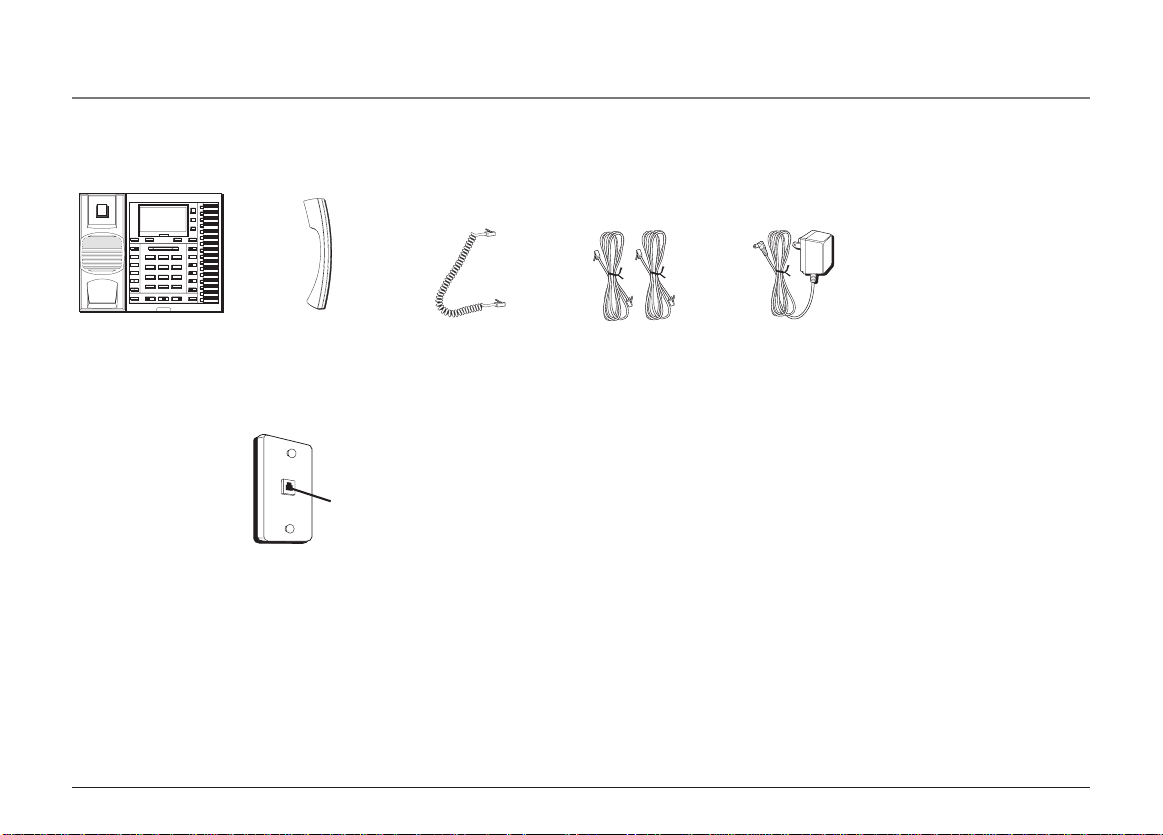
Parts Checklist
Make sure your package includes the following items:
INTERCOM/MEMORY LOG
INT.
DIRECTORY
1
MEM.
INT.
2
MEM.
MENU
INT.
3
MEM.
INT.
STORE
4
MEM.
INT.
5
MEM.
NEW MESSAGE
REVIEW
1
GHI4JKL5MNO
PQRS7TUV8WXYZ
TONE
0
*
HEADSET SPEAKER MUTE
INT.
6
MEM.
INT.
7
MEM.
INTERCOM
INT.
8
MEM.
CONFER
INT.
9
ABC2DEF
3
MEM.
INT.
LINE 4
10
MEM.
6
INT.
11
MEM.
LINE 3
INT.
12
MEM.
9
LINE 2
INT.
13
MEM.
INT.
OPER
LINE 1
#
14
MEM.
INT.
15
MEM.
HOLD
INT.
16
MEM.
DELETE EXIT SELECT/SAVE DIAL
PRIVACY
PAGE
TRANSFER
PAUSE
REDIAL
VOLUME
FLASH
Base Handset
Wall plate
Handset cord Line cords
Telephone Jack Requirements
AC power supply
To use this phone, you will need an RJ11C (for a single line) or a RJ14C (for two lines) type
modular phone jack, which might look like the one pictured here, installed in your home. If
Modular
telephone
line jack
you don’t have either modular jack, call your local phone company to find out how to get
one installed.
VERY IMPORTANT: In order to achieve full system operation (i.e. intercom, page, etc.), Line 1 must be
connected and must be common to all phones connected to the system. Only other 25403 or 25404
models are compatible for full system operation. Connecting phones other than the 25403/25404 to
Line 1 may inhibit the intercom and paging operations.
For proper operation of intercom, page function, etc., DO NOT connect a DSL modem to Line 1.
To transfer a call from one station to another, the two stations should be connected to the same line.
6
Page 7
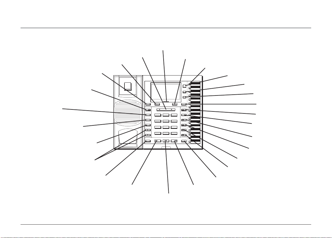
Base Layout
PAGE button
PRIVACY button
TRANSFER button
PAUSE/REDIAL button
DELETE button
NEW MESSAGE indicator (Not applicable to model 25403)
REVIEW button
SELECT/SAVE button
EXIT button
INTERCOM/MEMORY LOG
INT.
DIRECTORY
1
MEM.
INT.
2
MEM.
MENU
INT.
3
MEM.
INT.
STORE
4
MEM.
INT.
5
MEM.
DELETE EXIT SELECT/SAVE DIAL
NEW MESSAGE
PRIVACY
PAGE
TRANSFER
PAUSE
REDIAL
VOLUME
FLASH
REVIEW
ABC2DEF
1
GHI4JKL5MNO
PQRS7TUV8WXYZ
OPER
TONE
0
*
HEADSET SPEAKER MUTE
3
6
9
#
INT.
6
MEM.
INT.
7
MEM.
INTERCOM
INT.
8
MEM.
CONFER
INT.
9
MEM.
INT.
LINE 4
10
MEM.
INT.
11
MEM.
LINE 3
INT.
12
MEM.
LINE 2
INT.
13
MEM.
INT.
LINE 1
14
MEM.
INT.
15
MEM.
HOLD
INT.
16
MEM.
Connections & Setup
MEMORY buttons
DIRECTORY button
MENU button
STORE button
DIAL button
INTERCOM button
CONFER button
LINE 4 button
LINE 3 button
VOLUME button
FLASH button
HEADSET button
LINE 2 button
LINE 1 button
HOLD button
MUTE button
SPEAKER button
7
Page 8

Connections & Setup
Important Installation Information
• Never install telephone wiring during a lightning storm.
• Never install telephone jacks in wet locations unless the jack is specifically designed for wet locations.
• Never touch non-insulated telephone wires or terminals, unless the telephone line is disconnected from the network.
• Use caution when installing or modifying telephone lines.
•Temporarily disconnect any equipment connected to the phone such as faxes, other phones, or modems.
Important Installation Guidelines
• Install telephone near both a telephone (modular) jack and an electrical power outlet.
• Avoid sources of noise, such as a window by a busy street, and electrical noise, such motors, microwave ovens, and fluorescent lighting.
• Avoid heat sources, such as heating air ducts, heating appliances, radiators, and direct sunlight.
• Avoid areas of excessive moisture or extremely low temperature.
• Avoid dusty locations.
• Avoid other cordless telephones or personal computers.
CAUTION: Always disconnect all phone cords from the base unit before battery installation or replacement.
8
Page 9
Installing the Phone
Connections & Setup
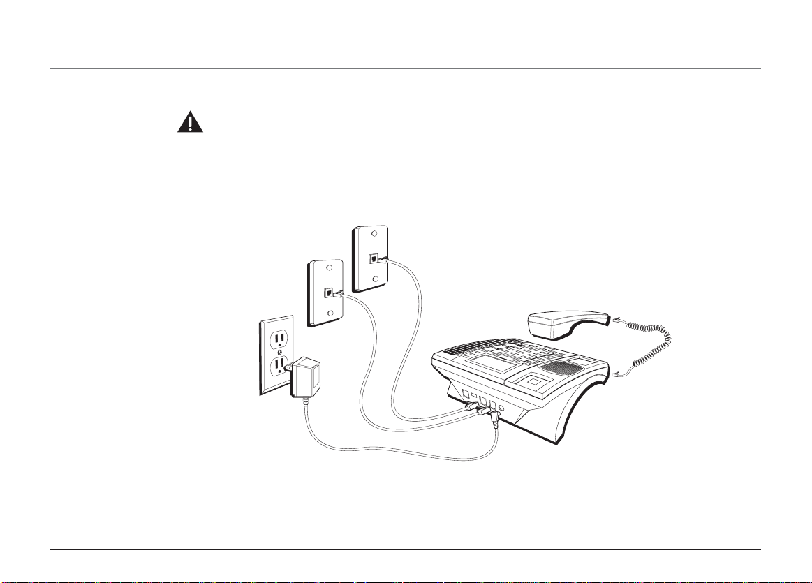
The phone may be connected to two 2-line (RJ14C) wall jacks or four single line (RJ11C)
wall jacks to accomodate all four lines.
1. Choose an area near an electrical outlet and telephone wall jack. Your phone should be
placed on a level surface, such as a table top or desk.
2. Install 3 AA-size alkaline batteries (not included) for back up power in the event of a
power failure.
• Use a screwdriver to loosen and lift up the battery compartment door located on
the bottom of the phone.
• Insert the batteries as shown on the diagram inside the battery compartment.
• Snap the battery compartment door back into place and tighten the screw.
NOTE: If the low battery icon appears in the display, you need to replace the batteries. It is important
that you replace them as soon as possible to maintain unit operation when electrical power is off. As a
precaution, you may want to write down any stored information you do not want erased.
IMPORTANT: If you are not going to use the telephone for more than 30 days, remove the batteries
because they can leak and damage the unit.
9
Page 10
Connections & Setup
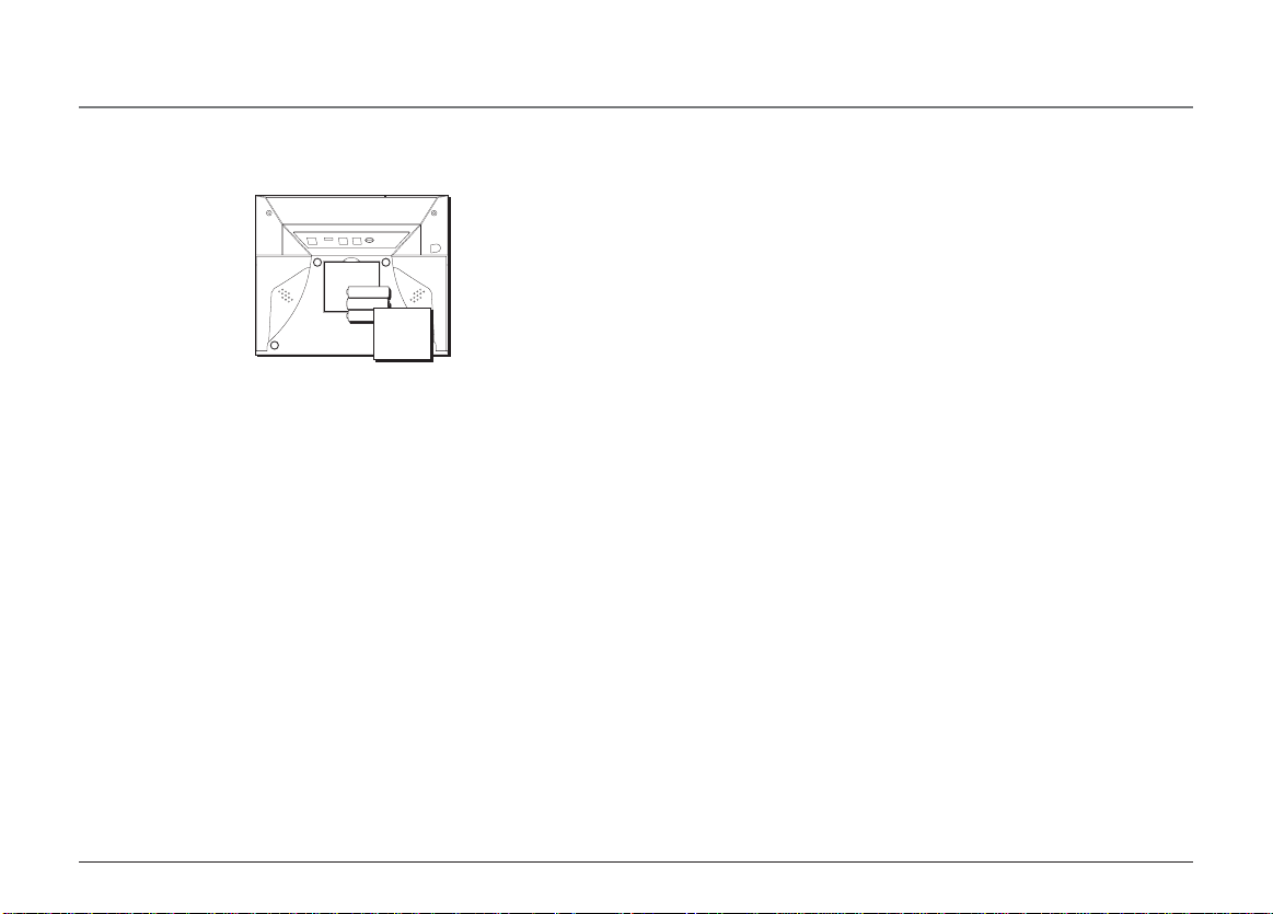
3. Plug the AC power supply cord into an electrical outlet and the DC connector into the back of the base.
4. Connect the telephone line cords:
CAUTION: Use only the ATLINKS USA 5-2495 power supply that is compatible with this unit. Using other power supplies may
damage the unit.
If you have two dual line wall jacks installed in your home/office, plug one end of the straight telephone line
cord tagged as "LINE 1+2" into the jack marked LINE 1 + 2 and one end of the other straight line cord into the
other jack on the back of the base. Plug the other end of each line cord into the dual-line wall jacks.
LINE 1 + 2
LINE 3 + 4
10
Page 11
Connections & Setup
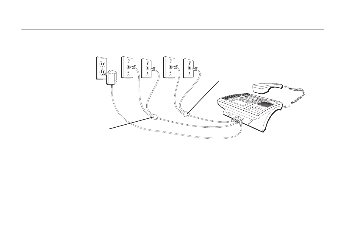
If you have four single-line wall jacks installed in your home/office, you must use adapters/couplers (not
included) to combine the four single telephone lines into two dual lines. The adapter/coupler may look similar to
the one pictured here and can be purchased from your local telephone products retailer.
Adapter/coupler LINE 1 + 2
Adapter/coupler LINE 3 + 4
NOTE: To use four lines, you must have four telephone lines with unique telephone numbers. If you only have one telephone line, this
phone will still operate, but only as a single line telephone.
Unit Initialization:
After you connect the power supply and Line 1 to the unit, the system automatically searches for and sets up a
phone ID. To set your own Phone ID, or change your phone ID, follow the steps in the Phone ID section.
You may connect up to 16 RCA 25404 and/or RCA 25403 phones to the system at one time. Features like
intercom, page and call transfer may be used among the units, but Line 1 must be common for all 25404 or
25403 units for these features to work properly. You may choose to share or privatize lines 2, 3 and 4.
11
Page 12

Connections & Setup
5. Connect the handset cord:
Connect one end of the coiled handset cord to the jack on the side of the base and the other end into the jack in the handset, and place
the handset in the cradle.
6. Check for a dial tone:
Lift the handset and listen for a dial tone. If you hear a dial tone, the phone is properly installed.
Data Port
This phone has a data port jack to connect an auxiliary phone device, such as a fax machine, computer modem, answering machine, or even a
cordless phone.
The data port switch on the back of the phone controls the data port jack so you can choose line 1, line 2, line 3, or line 4.
Use the data port to hook up your fax machine, for example, and then set the data port switch to line 4 in order to receive faxes on the
phone number for line 4.
If you are talking to someone on line 4 and want that person to fax something to you, change the data port switch to line 2 or line 3, and
give the person on-line the phone number for line 2 or line 3. Your fax machine now can receive calls on line 2, line 3, or line 4.
IMPORTANT: Be sure to switch the fax machine back to the normal line when you are done because outside callers who do not know that you have switched lines will
not be able to reach your fax machine if they dial the line 4 number.
System Verification
Use the following procedures to test system configuration and identify possible line connection errors. The phone must be connected to the
power outlet, Line 1 must be connected to the LINE 1 + 2 jack, and the phone must have a phone ID.
VERY IMPORTANT: In order to achieve full system operation (i.e. intercom, page, etc.), Line 1 must be connected and common to all phones on the system. Only other
25403 or 25404 models are fully compatible.
12
Page 13

Connections & Setup
Other System Phones
1. Press LINE 1.
2. Look at all the other stations. If they all indicate line 1 is being used, the connection is correct.
OR
1. Press the INTERCOM button. The display shows INTERCOM and ENTER CALLING PHONE ID.
2. Enter a phone ID by pressing an Intercom/Memo Log button (1-16). The display shows the phone ID you entered. If the phone ID you
entered is connected to the system, you will hear a ring back tone (call through tone) at your phone. If the phone ID is not connected to
the system, you will hear an error tone. NO ANSWER shows in the display and intercom is cancelled.
Programing the Telephone
This telephone has several programmable functions.
Language
Set the display language to show messages in either English, Spanish, or French.
1. Press the MENU button while in standby mode. The cursor in the display points to SET LANGUAGE.
2. Press the SELECT button.
3. Use the REVIEW < or > button to scroll to English, Espanol, or Francais. The default is English.
4. Press the SELECT button to save.
Ringer Tone
The ringers for all four lines may be set independent of one another.
1. Press the MENU button while in standby mode.
2. Use the REVIEW < or > button to scroll to SET PHONE OPTIONS.
13
Page 14

Connections & Setup
3. Press the SELECT button.
4. Use the REVIEW < or > button to scroll to SET RING TONE.
5. Press the SELECT button. The ringer tone settings for each of the four telephone lines show in the display.
6. Use the REVIEW < or > button to scroll to through each ringer tone for LINE 1. A sample ringer tone is generated when you scroll to
individual ringer tones. Choose from eight different tones, or turn the ringer OFF.
NOTE: If you select OFF, the cursor automatically moves to the CID ON/OFF option. Use the REVIEW < or > button to select CID ON or OFF. (ON allows the unit to detect
and display CID records for the corresponding telephone line. OFF disables the function for the corresponding telephone.) Press the SELECT button.
NOTE: On model 25403, you cannot select CID ON/OFF.
7. Press the SELECT button to save. The cursor automatically moves to LINE 2.
8. Repeat steps 6 and 7 for each telephone line. After you select the ringer tone for LINE 4, press the EXIT button.
NOTE: The line indicators flash for incoming calls even if the ringer is disabled.
Priority Line
The priority line (one of the four lines) has to have precedence over the other three lines.
1. Press the MENU button while in standby mode.
2. Use the REVIEW < or > button to scroll to SET PHONE OPTIONS.
3. Press the SELECT button.
4. Use the REVIEW < or > button to scroll to SET PRIORITY LINE.
5. Press the SELECT button.
6. Use the REVIEW < or > button to scroll to 1, 2, 3, or 4. The default is LINE 1.
7. Press the SELECT button to save.
14
Page 15

Connections & Setup
Delay Ring
Use this setting to delay the Central Office ring.
1. Press the MENU button while in standby mode.
2. Use the REVIEW < or > button to scroll to SET PHONE OPTIONS.
3. Press the SELECT button.
4. Use the REVIEW < or > button to scroll to SET DELAY RING.
5. Press the SELECT button.
6. Use the REVIEW < or > button to scroll to 0 ring up to 10 rings.
7. Press the SELECT button to save.
Phone ID
1. Press the MENU button while in standby mode.
2. Use the REVIEW < or > button to scroll to SET PHONE OPTIONS.
3. Press the SELECT button.
4. Use the REVIEW < or > button to scroll to SET PHONE ID.
5. Press the SELECT button.
6. Press the SELECT button again to automatically set the phone ID, or press any memory button (1-16) to assign a phone ID.
NOTE: The Phone ID (01-16) is unique. If you manually select a phone ID that belongs to another unit on the system, NOT AVAILABLE shows in the display. Press
SELECT or choose another memory button.
15
Page 16

Connections & Setup
NOTE: If the phone cannot find an ID, determine if there are too many phones connected to the system. A maximum of 16 phones can be connected in the system at
one time.
NOTE: To changing a phone ID, press the SELECT button. Select the new ID by pressing the corresponding memory location button (1-16), or press the SELECT button
to automatically search for and set the ID. You may press the EXIT button at any time to exit , except after ID searching starts.
Phone Name
1. Press the MENU button while in standby mode.
2. Use the REVIEW < or > button to scroll to SET PHONE OPTIONS.
3. Press the SELECT button.
4. Use the REVIEW < or > button to scroll to SET PHONE NAME.
5. Press the SELECT button.
6. Use the touch-tone pad to enter the phone name (up to 8 characters). More than one letter is stored in each of the number keys. For
example, to enter Bill Smith, press the 2 key twice for the letter B. Press the 4 key 3 times for the letter I. Press the 5 key 3 times for the letter
L. Press the 5 key 3 times for the second letter L, and press the 1 key to insert a space between the first and last name. Press the 7 key 4 times
for the letter S; press the 6 key once for the letter M; press the 4 key 3 times for the letter I; press the 8 key for the letter T; press the 4 key
twice for the letter H.
7. Press the SELECT button to save.
NOTE: The Phone Name and ID shows in the display when the phone is idle.
Intercom Auto Answer
For “hands-free” operation, the phone can be set to automatically answer an intercom call.
TIP: You may also use this feature for room monitoring.
1. Press the MENU button while in standby mode.
2. Use the REVIEW < or > button to scroll to SET PHONE OPTIONS.
16
Page 17

3. Press the SELECT button.
4. Use the REVIEW < or > button to scroll to INTERCOM AUTO ANS.
5. Press the SELECT button.
6. Use the REVIEW < or > button to choose YES or NO.
7. Press the SELECT button to save.
Flash Time
1. Press the MENU button while in standby mode.
2. Use the REVIEW < or > button to scroll to SET PHONE OPTIONS.
3. Press the SELECT button.
4. Use the REVIEW < or > button to scroll to SET FLASH TIME.
5. Press the SELECT button.
6. Use the REVIEW < or > button to scroll through the flash time options. You may choose 100ms or 600ms.
7. Press the SELECT button to save.
NOTE: You may press the EXIT button at any time to exit.
Call Alert Tone
Turn on the Call Alert to hear a tone for incoming calls while you are on the telephone.
1. Press the MENU button while in standby mode.
2. Use the REVIEW < or > button to scroll to SET PHONE OPTIONS.
3. Press the SELECT button.
4. Use the REVIEW < or > button to scroll to CALL ALERT TONE.
Connections & Setup
17
Page 18

Connections & Setup
5. Press the SELECT button.
6. Use the REVIEW < or > button to scroll to ON or OFF.
7. Press the SELECT button to save. The cursor automatically moves to LINE 2.
8. Repeat steps 6 and 7 for each telephone line. After you select a tone for Line 4, press the EXIT button.
No Unknown/Blocked (Not applicable to model 25403.)
This option allows you to decide whether the unknown or blocked caller ID calls are saved or not. If you select YES, the unknown or blocked
calls will be saved.
1. Press the MENU button while in standby mode.
2. Use the REVIEW < or > button to scroll to SET PHONE OPTIONS.
3. Press the SELECT button.
4. Use the REVIEW < or > button to scroll to NO UNKNOWN/BLOCKED.
5. Press the SELECT button.
6. Use the REVIEW < or > button to scroll to YES or NO. The default is YES.
7. Press the SELECT button to save.
Display Contrast
Adjust the display contrast to one of four contrast levels.
1. Press the MENU button while in standby mode.
2. Use the REVIEW < or > button to scroll to SET LCD CONTRAST.
3. Press the SELECT button. The MIN and MAX contrast scale shows on the display.
4. Use the REVIEW < or > button to adjust the contrast. The display instantly adjusts with each press of the < or > button.
5. Press the SELECT button to save the desired contrast level.
18
Page 19

Connections & Setup
Local Area Code (Not applicable to model 25403.)
1. Press the MENU button while in standby mode.
2. Use the REVIEW < or > button to scroll to SET AREA CODE.
3. Press the SELECT button.
4. Use the REVIEW < or > button to scroll to LOCAL AREA CODE.
5. Press the SELECT button. Enter Number shows in the display.
6. Use the touch tone pad on your phone to enter your local area code.
7. Press the SELECT button to save.
NOTE: If you make a mistake, press DELETE to erase the wrong digit.
Regional Area Codes (Not applicable to model 25403.)
Depending on your location, you may need to set up to six regional area codes. Setting Regional Area Codes helps the phone
determine the number format to display when a valid CID record is received. Call records matching any of the set regional area
codes are displayed as 10 digits.
NOTE: If the CID telephone number does not display correctly, you may not be able to dial back the number from the Caller ID menu.
You may need to set regional area codes if you reside in an area which:
• uses multiple area codes
• uses overlapping area codes
• requires 10-digit dialing.
1. Press the MENU button while in standby mode.
2. Use the REVIEW < or > button to scroll to SET AREA CODE.
19
Page 20

Connections & Setup
3. Press the SELECT button.
4. Use the REVIEW < or > button to scroll to REGIONAL AREA CODES.
5. Press the SELECT button. All six regional area code fields and Enter Number show in the display.
6. Use the touch tone pad on your phone to enter up to six regional area codes.
7. Press the SELECT button to save.
NOTE: If you make a mistake, press the DELETE button to erase a wrong digit.
Manually Setting the Time and Date
The time and date is automatically set when you receive the first CID call. To manually reset the time and date, follow the steps below.
NOTE: Automatic time set is not applicable to model 25403.
1. Press the MENU button while in standby mode.
2. Use the REVIEW < or > button to scroll to SET TIME & DATE.
3. Press the SELECT button.
4. Use the REVIEW < or > button to scroll to SET CLOCK
5. Press the SELECT button, and the cursor moves to the hour field.
6. Use the REVIEW < or > button to button to select the hour.
NOTE: AM or PM will be set accordingly with selected hour
7. Press the SELECT button, and the cursor moves to the minute field.
8. Use the REVIEW < or > button to select the minutes.
9. Press the SELECT button, and the cursor moves to the month field.
10. Use the REVIEW < or > button to select the month.
11.Press the SELECT button, and the cursor moves to the date field.
20
Page 21

Connections & Setup
12. Use the REVIEW < or > button to select the date.
13. Press the SELECT button, and the cursor moves back to the hour field.
14. Press the EXIT button.
NOTE: You may press EXIT at any step in the process. It is not necessary to re-program the complete time & date if you only want to adjust certain fields (i.e.; hour only).
Hour Format
You may set this phone to a 12 or 24-hour format. The default is 12-hour format.
1. Press the MENU button while in standby mode.
2. Use the REVIEW < or > button to scroll to SET TIME & DATE.
3. Press the SELECT button.
4. Use the REVIEW < or > button to scroll to SET HOUR FORMAT.
5. Press the SELECT button.
6. Press the REVIEW < or > button to select 12-HOUR or 24-HOUR.
7. Press the SELECT button to save.
Restoring the Default Settings
This feature allows you to reset the menu to the original factory default settings.
1. Press the MENU button while in standby mode.
2. Use the REVIEW < or > button to scroll to RESTORE TO DEFAULTS.
3. Press the SELECT button.
4. Use the REVIEW < or > button to scroll to YES or NO.
5. Press the SELECT button to save.
21
Page 22

Operation
Basic Operation
Your phone provides the convenience of accessing four separate telephone lines, each obtained from the telephone company and each
having its own phone number. This is generally applicable to small offices. It provides for 16 telephones (or stations) to share multiple lines.
Each station is interconnected to all others by an intercom.
Making Calls with the Handset
1. Pick up the handset and the phone automatically selects the priority line. If the priority line is occupied, it selects an open line.
2. Wait for a dial tone, then dial a phone number.
3. Hang up the handset when finished.
Making Calls with the Speakerphone
1. Press the SPEAKER button and the phone automatically selects the priority line. If the priority line is occupied, it selects an open line.
OR
Press a line button to select a line.
2. Wait for a dial tone then dial a phone number.
3. Press SPEAKER when finished.
NOTE: Only one-way conversation is possible in speakerphone mode. When you are speaking, you are transmitting. When you are listening, you are receiving. You
can’t do both at the same time. The phone will automatically switch between transmitting and receiving depending on the level of the voice or the room noise picked
up by the speakerphone mic.
NOTE: If a line goes off-hook, the call timer counts time until all the lines go on hook. The timer serves for 4 lines.
22
Page 23

Operation
Making Calls with the Optional Headset
1. Connect the headset plug to the HEADSET jack on the side of the base.
2. Adjust the headset to rest comfortably on top of your head and over your ear.
3. Move the microphone to approximately 2 to 3 inches from your mouth.
4. Press the HEADSET button and the phone automatically selects the priority line. If the priority line is occupied, it selects an open line.
5. Wait for a dial tone, then dial a phone number.
6. Press HEADSET when finished.
CAUTION: Use only the ATLINKS USA, Inc. 5-2425 headset that is compatible with this unit.
NOTE: If the headset is not connected, an error tone is heard when the HEADSET button is pressed.
Pre-dialing
1. With the phone idle and the handset on the cradle, manually enter the telephone number. The telephone number shows in the display.
2. Press the DIAL or SPEAKER button, or lift the handset to take a line, and the telephone number is automatically dialed.
NOTE: The unit displays "< or > to adjust format" below the telephone number you just entered. If desired, you may press the REVIEW < or > button, within 5 seconds,
to change the format. When finished, press the DIAL button to immediately dial or wait for the phone to dial automatically.
Answering Calls
If you receive a call on the priority line,
1. Pick up the handset, OR
2. Press the SPEAKER button (speakerphone mode), OR
23
Page 24

Operation
3. Press the HEADSET button (headset mode).
4. When finished, hang up the handset, press the SPEAKER button or press the HEADSET button.
If you receive a call on a line other than the priority line,
1. Pick up the handset and press the corresponding line button, OR
2. Press the SPEAKER button and press the corresponding line button (speakerphone mode), OR
3. Press the corresponding line button, and then press the HEADSET button (headset mode).
4. When you are finished, hang up the handset, press the SPEAKER button, or press the HEADSET button.
NOTE: Whether you are making or receiving a call, the caller is disconnected if you press another line without putting the call on hold first.
Switching Between the Speakerphone, Handset, and Headset
To switch to the speakerphone, press SPEAKER. The speakerphone indicator turns on.
To switch to the handset, pick up the handset. The speakerphone or headset turns off.
To switch to the headset, press HEADSET to enable the headset. The headset indicator turns on.
Mute
To have a private, off-line conversation, use the MUTE feature. The party on the other end of the line cannot hear you, but you can still hear
them.
1. Press MUTE to activate the mute feature. The mute indicator turns on.
2. Press MUTE again to turn it off.
NOTE: Switching from speakerphone to handset or headset cancels mute.
24
Page 25

Operation
Do Not Disturb
1. When the unit is idle, press the PRIVACY button. The Privacy indicator flashes and the last setting is displayed.
2. Use the REVIEW < or > button to the duration. You may choose from 15 minutes, 30 minutes, 45 minutes, 1 hour, or 2 hours and increase
the duration by 1 hour intervals up to 24 hours.
3. Press the SELECT button to confirm.
This feature is set at individual telephones to disable (silence) an incoming ring signal, intercom ring, or page. To program the duration of do
not disturb, see “Do Not Disturb.”
1. While the phone is not in use, press PRIVACY. The indicator blinks and the display shows how long the ringer will be disabled. When there
is an incoming call or an intercom call, the status indicators function as normal but the phone will not ring.
2. To cancel, press PRIVACY again.
Hold
Placing a Call on Hold
1. Press the HOLD button. The indicator for the line on hold flashes green.
2. Hang up or press another line button.
The phone emits a beep every 30 seconds as a reminder. At the other stations, the indicator blinks red but no beep is heard.
NOTE: If you put a call on HOLD while in PRIVACY mode, no one but you can access the line on hold. Anyone trying to access the line receives an error tone.
Releasing a Call
Press the button for line on hold. The phone automatically goes into speakerphone mode.
NOTE: If you want to change modes, lift the handset to switch to the handset, or press the HEADSET button to use the headset.
NOTE: The call on hold can be picked up at any station using this procedure.
25
Page 26

Operation
Flash
Use the FLASH button to activate custom calling services such as call waiting or call forwarding, which are available through your
local phone company.
Redial
1. Pick up the handset or press the SPEAKER button (speakerphone mode), and the priority line is automatically selected, OR
2. Press the HEADSET button (headset mode), followed by a line button.
3. Press the REDIAL button
NOTE: The redial function will not operate if the number to be redialed contains more than 32 digits. If the number is longer than that, you will hear an error tone.
Reviewing the Redial Numbers
Your phone records up to six previously dialed phone numbers.
1. When the phone is idle, press the REDIAL/PAUSE button.
2. Use the REVIEW < or > button to view the last six previously dialed numbers.
3. While the preferred number is displayed, pick up the handset or press the SPEAKER, DIAL, or a line button to dial the phone number.
NOTE: If you do not select a line button, the line is automatically seized and the number is dialed accordingly.
Transferring a Call to Another Station
1. With the caller on the line, press the TRANSFER button.
2. Press an Intercom/Memo Log button (1-16) that corresponds to the station you want to transfer the call to. The line’s indicator blinks
yellow until the party picks up the transferred call. Once the call is picked up, the indicator stays red. The indicator on the receiving
party’s line rapidly flashes red and rings.
• If the transferred call is not picked up at the other station within 45 seconds. The transfer cancels, the line is put on hold, and the line
indicator flashes green.
26
Page 27

Operation
• If the party at the other station doesn’t pick up the transferred call, and you want to attempt to transfer to another station, press the
line button and repeat the transfer process from step 1.
Receiving a Transferred Call from Another Station
If a call is transferred to your station, the line indicator flashes red. To answer the call, press that line button.
If you are on the line when a call is transferred to you, you will hear beeps to alert you of the incoming call. Put your current call on hold by
pressing HOLD, and then pick up the incoming call by pressing the line button.
NOTE: During the transfer, the only two stations that can access the line are: a) the transferring station, or; b) the station receiving the transfer.
VERY IMPORTANT: To transfer a call from one station to another, the two stations should be connected to the same line.
Message Waiting (Not applicable to model 25403.)
Provided your phone company offers voice messaging service and you subscribe to it, the NEW MESSAGE indicator flashes when the phone is
not in use to indicate there is a message waiting. Also, from the display, you can find which line has message waiting. The indicator stops
flashing after the message is reviewed.
Privacy
While in use, a line can be secured so that no one else can listen to the conversation. This feature only applies to 25403/25404 phones.
However, other phone which are not compatible with these models can still access the line.
Providing Privacy
At any time during a conversation, you can use the privacy feature to secure the line.
1. While on a line, press the PRIVACY button. The indicator turns on.
2. To cancel, press PRIVACY again or hang up.
NOTE: If you put a call on hold while in privacy mode, no one but you can access the line on hold.
27
Page 28

Operation
Volume
The ringer, speaker, and handset/headset volume is set independently with the VOLUME up and down buttons. There are 8 possible volume
settings per mode. The volume indicator scale is displayed during volume adjustment.
Ringer Volume
1. While the phone is on the hook, press the VOLUME up or down button. The phone rings according to the current setting.
2. Tap the up or down button to adjust the volume one level at a time. The phone stores the setting after the last button press.
NOTE: To turn the ringer off, on, or change the ringing pattern, see Setting the Ringer Tone.
Speakerphone, Handset, and Headset Volume
While the phone is in use, press the VOLUME up or down buttons until you reach the desired volume. The phone stores the setting after the
last button press.
Conference Calls
This feature allows you to have a 3-way conversation using any combination of 2 lines.
To connect and conference
1. To make a call, press the line you want and dial the telephone number. If you already have someone on the line, skip to step 2.
2. Press the HOLD button to place the call on hold.
3. Press another line button and dial the telephone number of the party you want to conference with.
4. Press the CONFERENCE button.
5. Speak to both parties.
NOTE: If you have more than one line on hold, and you want to have a conference call, you must first select the line on which you want to conference.
28
Page 29

Operation
To disconnect one party:
Press the line button for the person you want to continue speaking with, and the other party is automatically disconnected.
To disconnect both parties:
Hang up the handset, or press the SPEAKER or HEADSET button.
NOTE: If you press the HOLD button to put them on hold first, you may then disconnect from each party individually.
Intercom Calls
One -Touch Intercom
NOTE: If the INTERCOM indicator is turned on (solid red), the intercom is in use. You must wait until the indicator turns off before making an intercom call.
1. Press the Intercom/Memo Log button (1-16) for the station you want to intercom with. The SPEAKER turns on.
Alternately, you may press the INTERCOM button, then press the Intercom/Memo Log button (1-16) for the stations you want to intercom
with. The speakerphone automatically turns on.
NOTE: If you want to switch to the handset, pick it up and continue speaking. To switch to the headset press the HEADSET button.
NOTE: The handset, headset, or speakerphone cannot be active when an intercom call is initiated (the handset should be on the cradle and the speakerphone and
headset turned OFF.)
NOTE: To abort intercom call, press SPEAKER button.
2. To end the intercom call, hang up.
NOTE: If the receiving station does not answer within 45 seconds, the intercom call is cancelled. You will hear an error tone and NO ANSWER shows in the display.
Answering an Intercom Call
When you receive an INTERCOM call, the INTERCOM indicator flashes red, and the display shows the caller’s name and phone ID.
29
Page 30

Operation
NOTE: If you are using the speakerphone, press the INTERCOM button to answer. If you are using the headset (headset indicator flashes), press the INTERCOM
button., or when the intercom indicator turns green, lift the handset and begin speaking.
NOTE: Press SPEAKER or lift the handset to automatically select a party. If you receive an incoming call and intercom call at the same time the unit automatically
selects the ringing line.
Intercom Hold
1. Make an intercom call or answer an intercom call.
2. Press the HOLD button. The Intercom indicator flashes green.
NOTE:
• When the intercom is on hold, you may not receive another intercom.
• If the other party terminates intercom, intercom hold is also released.
Intercom Conference Calls
This feature allows you to have a 3-way conversation using the intercom feature and an open line.
1. Place a call or make an intercom call.
2. Press the HOLD button.
3. Place a call on another line or make an intercom call.
4. Press the CONFERENCE button.
5. Speak to both parties.
NOTE: If you have more than one party on hold (telephone line or intercom), you must select the line for the party you want to conference with.
To disconnect one party:
Press the line or intercom button for the person you want to continue speaking with, and the other party is automatically disconnected.
30
Page 31

Caller ID
To disconnect both parties:
Hang up the handset, or press the SPEAKER button.
NOTE: If you press the HOLD button to put them on hold first, you may then disconnect from each party individually.
Paging All Stations
1. Lift the handset.
2. Press the PAGE button and listen for the beep. The other stations not in use automatically activate their speakerphones and receive your page.
3. Speak into the handset. You have 30 seconds to page in this mode. After 30 seconds, the page is cancelled.
4. When finished, hang up the handset.
NOTE: You will not receive a page when Do Not Disturb is turned on.
NOTE: Paging can be done with optional headset.
Caller ID (CID)
NOTE: The Caller ID section of this user's guide (from page 31 to page 34) is not applicable to model 25403.
Summary Screen
The summary screen shows the current time, current date, number of CID records to be reviewed and total number of records saved to CID
memory. It is displayed until any button is pressed. Within 60 seconds of receiving a new call, the new caller information is displayed.
Phone ID
Battery indicator
Time and date
(01)JOHN
00 New CALLS
00 Total CALLS
12:34 PM 12/25
Name of phone
CID records
waiting to be
reviewed
Number of records in CID memory
31
Page 32

Caller ID
Receiving and Storing CID Records
This unit receives and displays information transmitted by your local phone company. This information can include the phone number, date
and time; or the name, phone number, date and time. The unit can store up to 99 calls for later review. When the memory is full, a new call
automatically replaces the oldest call in memory. NEW appears in the display for calls received that have not been reviewed. The line number
for the call received is also displayed.
In case multiple incoming calls come in at the same time, the CID information is displayed according to the unit’s priority line setting.
Example: the priority line is 3.
Reviewing CID Records
INCOMING CALL
LINE 2
JOHN SMITH
1-317-123-4567
12:34 PM 12/25
L3: 555-1234
L1:
L2: 1-317-123-4567
L4:
• Press the REVIEW < or > button to scroll through the call records.
NOTE: If you press the < button, the oldest record shows in the display. If you press the > button, the
most recent record shows in the display.
• When you scroll to the start/end of the list, START/END appears in the display.
Saving a CID Record to the Intercom/Memo Log or to Phone Book Memory
1. While a name and telephone number shows in the display, if you need to edit the
information, press the SELECT button and follow the steps for Storing a Name and
Number in Memory.
2. If you do not need to edit the name or number, press the STORE button.
3. To store data in the Phone Book Directory, press the DIRECTORY button,
OR
To store data in the Intercom/Memo Log, press a memory log button (1-16).
32
Page 33

Caller ID
CID REVIEW NEW
LINE 2
JOHN SMITH
1-317-123-4567
12:34 PM 12/25
Deleting a CID Record
To delete the record shown in the display, press the DELETE button once.
Deleting All Call Records
This feature allows you to clear all CID records at once.
1. While viewing a CID record, press and hold the DELETE button. PRESS DELETE AGAIN
CLEAR ALL CALLER ID shows in the display.
2. Press the DELETE button again to confirm.
Dialing Back
When reviewing CID records, you can dial back the numbers showing on the display by pressing the DIAL button.
If You Programmed Your Local Area Code
1. Use the REVIEW < or > button to display the number you want to dial.
2. Press the DIAL button. If you see a number with 7 digits (i.e.555-1234), then the call was received from within your area code. However,
this does not guarantee the call is a local call. If you see a number with 11 digits (i.e.1-234-555-1234), then the call received was not
from your area code. The unit displays “Press < or > to adjust .”
3. To adjust the phone number format, use the REVIEW < or > buttons. For instance, a 7-digit local number sometimes cannot be dialed
because it requires a 10-digit or 11-digit format. Use the REVIEW < or > buttons to scroll through 7, 10 and 11-digit numbers.
7-digits: 7-digit telephone number (i.e.555-5555)
10-digits: 3-digit area code +7-digit telephone number (i.e.425-555-5555)
11-digits: long distance code 1 +3-digit area code +7-digit telephone number
(i.e. 1-425-555-5555)
4. To dial the displayed number, pick up the handset or press DIAL again.
33
Page 34

Caller ID
If You Did Not Program Your Local Area Code
1. Use the REVIEW < or > button to display the number you want to dial. You will only see 10-digit numbers (i.e.234-555-1234).
2. Press DIAL to dial back. You may adjust the number format if “Press 65 to adjust ” shows in the display.
Call Waiting Caller ID
This feature allows you to see who is calling when you hear the call waiting beep. The caller identification information appears in the display
after you hear the tone.
•Press the FLASH button to put the person to whom you’re talking on hold and answer the incoming call.
IMPORTANT: To use all the features of this unit, you must subscribe to either the standard Name/Number Caller ID Service or Caller ID with Call Waiting Service. To
know who is calling while you are on the phone, you must subscribe to Caller ID with Call Waiting Service.
Memory Log and Phone Book (Directory) Memory
You may store data in the Phone Book Directory (up to 90 memories) or the Intercom/Memo Log (16 buttons located to the right of the
number pad on the base). The Phone Book and each Intercom/Memory Log stores up to 21 characters and 32 digits.
Storing a Number and Name in Memory
NOTE: To cancel the storing procedure at any time, press EXIT.
1. Press the STORE button. ENTER NUMBER is displayed.
2. Use the touch tone pad on your telephone to enter the telephone number you want to store. The numbers you enter show in the display.
NOTE: If you make a mistake, use the REVIEW < or > button to move the cursor to the incorrect digit, and press the DELETE button to delete.
3. Press SELECT. ENTER NAME is displayed.
34
Page 35

Memory
4. Use the touch-tone pad to enter a name (up to 21 characters). More than one letter is stored in each of the number keys. For example, to
enter Bill Smith, press the 2 key twice for the letter B. Press the 4 key 3 times for the letter I. Press the 5 key 3 times for the letter L. Press
the 5 key 3 times for the second letter L, and press the 1 key to insert a space between the first and last name. Press the 7 key 4 times for
the letter S; press the 6 key once for the letter M; press the 4 key 3 times for the letter I; press the 8 key for the letter T; press the 4 key
twice for the letter H.
NOTE: If you make a mistake, use the REVIEW < or > button to move the cursor to the incorrect digit, and press the DELETE button to delete.
5. Press STORE button. ENTER LOCATION is displayed.
6. Enter memory location:
Press the DIRECTORY button to save the record in the Phone Book memory),
OR
Press a MEMO log button (1-16) to save the record in that memory location.
7. Repeat steps 1-7 for any additional names and numbers you want to store, up to 90, in phone book memory.
NOTE: The storage procedure automatically cancels after 30 seconds if no keys are pressed.
Reviewing Phone Book (Directory) Memory
1. Press the DIRECTORY button. The first memory in the phone book is displayed (memories are stored in alphabetical order).
2. Use the REVIEW < or > button to scroll through the phone book memories, or use the touch tone pad on your phone to enter the
corresponding letters for the memory you want to review. For example, press the 5 key to display phone book memories that start with
the letter J. Press the 5 key twice to go to memories starting with the letter K.
3. Press the EXIT button when you are finished reviewing memories.
35
Page 36

Memory
Reviewing the Memo Log (memory location memory)
1. Press the DIRECTORY button.
2. Press the Intercom/MemoryLog button (1-16).
3. Press the EXIT button when you are finished reviewing memories.
Editing a Name or Number Stored in Phone Book (Directory) Memory
1. Press the DIRECTORY button.
2. Use the REVIEW < or > button to scroll to the desired memory record.
3. Press the SELECT button and edit the content according to the steps in the Storing a Name and Number in Memory section.
Editing a Name or Number Stored in a Memo Log (Memory Location)
1. Press the DIRECTORY button.
2. Press the Intercom/MemoryLog button (1-16).
3. Press the SELECT button and edit the content according to the steps in the Storing a Name and Number in Memory section.
Storing the Last Number Dialed
1. When the phone is idle, press the REDIAL/PAUSE button.
2. Use the REVIEW < or > button to view the last six previously dialed numbers.
3. While viewing the desired number, press the SELECT button.
4. Add the name as explained in the Storing A Name and Number in Memory section.
5. Press the STORE button. ENTER LOCATION shows in the display.
6. Press the DIRECTORY button to store the redial number in the Phone Book memory or press and Intercom/Memo Log button (1-16) to
store the redial number in that memory location.
36
Page 37

Memory
Storing a Pause in Memory
Use the REDIAL/PAUSE button to insert a delay in the dialing sequence of a stored telephone number when a pause is needed (for example,
when you must dial a 9 to get an outside line or when you must enter codes to access your bank’s information line).
Dialing a Stored Number
1. Pick up the handset, or press SPEAKER to automatically select a line. Or press the line you want to use.
2. Wait for a dial tone.
3. Press the Memo Log (memory location) button for the person you want to call. The number automatically dials.
OR
1. Press the DIRECTORY button.
2. Use the REVIEW < or > button to scroll through the phone book memories, or use the touch tone pad to enter the corresponding letters
for the memory you want to review. For example, press the 5 key to display phone book memories that start with the letter J. Press the 5
key twice to go to memories starting with the letter K.
3. Press the DIAL button. The number automatically dials.
Memory Delete/Clear
To delete a Phone Book memory:
1. Press the DIRECTORY button.
2. Use the REVIEW < or > button to scroll to the memory you want to delete.
3. Press the DELETE button and delete. DELETE again shows in the display.
4. Press the DELETE button again to confirm.
37
Page 38

Memory
To delete an Intercom/Memo Log:
1. Press the DIRECTORY button.
2. Press the corresponding button (1-16) for the Intercom/Memo Log you want to delete.
3. Press the DELETE button and delete. DELETE again shows in the display.
4. Press the DELETE button again to confirm.
NOTE: Press the EXIT button to cancel the "delete" function.
Clear All Memories
1. Press the MENU button while in standby mode.
2. Use the REVIEW < or > button to scroll to SET SET PHONE OPTIONS.
3. Press the SELECT button.
4. Use REVIEW < or > button to scroll to CLEAR ALL MEMORIES.
5. Press the SELECT button.
6. Use the REVIEW < or > button to scroll to Yes or No, No is the default.
7. Press the SELECT button to confirm.
NOTE: If you select YES, all the directory memories and direct access memories are cleared.
Chain Dialing
This process allows you to dial a succession of stored numbers from separate memory locations. This is useful when you must dial several
sequences of numbers, such as with frequent calls via a telephone company long distance provider.
38
Page 39

Other Information
For example Memory location
Local access number of long distance company 6
Authorization code (ID) 7
Long distance phone number 8
1. Press the line you want.
2. Press memory location 6.
3. Press memory location 7.
4. Press memory location 8.
Display Messages
The following special messages indicate the status of a message or the unit:
00 TOTAL CALLS The Caller ID memory log is empty. (Not applicable to model 25403.)
UNKNOWN CALLER The incoming call does not have Caller ID service or their service area is not linked to yours. If UNKNOWN CALLER appears
BLOCKED CALL The caller is registered as “Private Number ”and their Caller ID information is withheld. (Not applicable to model 25403.)
INCOMPLETE DATA Caller information has been interrupted or corrupted during transmission. (Not applicable to model 25403.)
NO DATA No Caller ID signal has been detected, or Caller ID service has not been activated. (Not applicable to model 25403.)
START/END You are at the beginning or the end of the Caller ID memory log. (Not applicable to model 25403.)
along with a calling number, the name information for that number was not available. (Not applicable to model 25403.)
Battery power level is low.
39
Page 40

Other Information
Operation By Battery
If the power cord is not plugged into the unit, and the battery is available, the unit enters Battery Operation Mode. In this mode, the unit
fully supports all operational features, except the intercom call function.
Operation without Power
If the power cord is not plugged into the unit and no battery is installed, the unit enters into No Power Operation mode. in this mode, the
user may:
1) use the handset to manually make a call on line 1 only,
2) answer a call on line 1 with the handset.
Troubleshooting Guide
No dial tone
• Check or repeat installation steps:
Make sure the telephone line cords are connected to the phone and the wall jack. Make sure the line cords are not damaged.
• Make sure the hook switch pops up when the handset is lifted.
• Check the SPEAKER button. Make sure the indicator is off.
• Disconnect the phone from the wall jack and connect another phone to the same jack. If there is no dial tone in the second phone, the
problem might be your wiring or local service.
You cannot be heard by the other party.
• Make sure the handset or headset cord is inserted properly and securely.
• Make sure the MUTE feature is not turned on.
40
Page 41

Other Information
Phone does not ring.
• Make sure the ringer is turned on.
• Make sure the Do Not Disturb feature is not activated.
•You may have too many extension phones on your line. Try unplugging some phones.
• See solutions for “No dial tone.”
Incoming voice too low or none at all.
• Check volume setting.
Memory dialing doesn’t work
• Did you program the memory location keys correctly?
• Did you follow proper dialing sequence?
Battery icon is blank or shows only one bar
• The three “AA” batteries need replacing or are improperly installed or not installed at all.
Intercom does not function correctly
• Make sure line 1 is connected properly and common to all phones on the system.
• Make sure all phone ID’s (station numbers) involved have been assigned.
Transfer does not function correctly
• Make sure receiver phones (stations) have same line connected.
Intercom indicator turns red and green alternately
• The station address needs to be re-assigned due to a duplicate station address in the system. See “Changing the Phone ID (Station Address)” .
41
Page 42

Other Information
General Product Care
To keep your telephone working and looking good, follow these guidelines:
• Avoid putting the phone near heating appliances and devices that generate electrical noise (for example, motors or fluorescent lamps).
• DO NOT expose to direct sunlight or moisture.
• Avoid dropping the handset, as well as other rough treatment to the phone.
• Clean the phone with a soft cloth.
• Never use a strong cleaning agent or abrasive powder because this will damage the finish.
• Retain the original packaging in case you need to ship the phone at a later date.
Service
If trouble is experienced with this equipment, for repair or warranty information, please contact customer service at 1-800-511-3180. If the
equipment is causing harm to the telephone network, the telephone company may request that you disconnect the equipment until the
problem is resolved.
This product may be serviced only by the manufacturer or its authorized service agents. Changes or modifications not expressly approved by
ATLINKS USA, Inc. could void the user’s authority to operate this product. For instructions on how to obtain service, refer to the warranty
included in this guide or call customer service at 1-800-511-3180.
Or refer inquiries to:
ATLINKS USA, Inc.
Manager, Consumer Relations
P O Box 1976
Indianapolis, IN 46206
Attach your sales receipt to the booklet for future reference or jot down the date this product was purchased or received as a gift. This
information will be valuable if service should be required during the warranty period.
Purchase date ___________ Name of store ____________________________________________________________________________
42
Page 43

Other Information
Limited Warranty
What your warranty covers:
• Defects in materials or workmanship.
For how long after your purchase:
• One year, from date of purchase. (The warranty period for rental units begins with the first rental or 45 days from date of shipment to the rental firm, whichever comes first.)
What we will do:
•Provide you with a new or, at our option, a refurbished unit. The exchange unit is under warranty for the remainder of the original product’s warranty period.
How you get service:
•Properly pack your unit. Include any cables, etc., which were originally provided with the product. We recommend using the original carton and packing materials.
• ”Proof of purchase in the form of a bill of sale or receipted invoice which is evidence that the product is within the warranty period, must be presented to obtain warranty
service.” For rental firms, proof of first rental is also required. Also print your name and address and a description of the defect. Send via standard UPS or its equivalent to:
ATLINKS USA, Inc.
c/o Thomson
11721 B Alameda Ave.
Socorro, Texas 79927
•Pay any charges billed to you by the Exchange Center for service not covered by the warranty.
• Insure your shipment for loss or damage. ATLINKS accepts no liability in case of damage or loss.
•A new or refurbished unit will be shipped to you freight prepaid.
43
Page 44

Other Information
What your warranty does not cover:
• Customer instruction. (Your Owner’s Manual provides information regarding operating instructions and user controls. Any additional information, should be
obtained from your dealer.)
• Installation and setup service adjustments.
• Batteries.
• Damage from misuse or neglect.
•Products which have been modified or incorporated into other products.
•Products purchased or serviced outside the USA.
• Acts of nature, such as but not limited to lightning damage.
Product Registration:
• Please complete and mail the Product Registration Card packed with your unit. It will make it easier to contact you should it ever be necessary. The return of the card is not
required for warranty coverage.
Limitation of Warranty:
• THE WARRANTY STATED ABOVE IS THE ONLY WARRANTY APPLICABLE TO THIS PRODUCT. ALL OTHER WARRANTIES, EXPRESS OR IMPLIED (INCLUDING ALL IMPLIED WARRANTIES
OF MERCHANTABILITY OR FITNESS FOR A PARTICULAR PURPOSE) ARE HEREBY DISCLAIMED. NO VERBAL OR WRITTEN INFORMATION GIVEN BY ATLINKS USA, INC., ITS AGENTS, OR
EMPLOYEES SHALL CREATE A GUARANTY OR IN ANY WAY INCREASE THE SCOPE OF THIS WARRANTY.
• REPAIR OR REPLACEMENT AS PROVIDED UNDER THIS WARRANTY IS THE EXCLUSIVE REMEDY OF THE CONSUMER. ATLINKS USA, INC. SHALL NOT BE LIABLE FOR INCIDENTAL OR
CONSEQUENTIAL DAMAGES RESULTING FROM THE USE OF THIS PRODUCT OR ARISING OUT OF ANY BREACH OF ANY EXPRESS OR IMPLIED WARRANTY ON THIS PRODUCT. THIS
DISCLAIMER OF WARRANTIES AND LIMITED WARRANTY ARE GOVERNED BY THE LAWS OF THE STATE OF INDIANA. EXCEPT TO THE EXTENT PROHIBITED BY APPLICABLE LAW, ANY
IMPLIED WARRANTY OF MERCHANTABILITY OR FITNESS FOR A PARTICULAR PURPOSE ON THIS PRODUCT IS LIMITED TO THE APPLICABLE WARRANTY PERIOD SET FORTH ABOVE.
How state law relates to this warranty:
• Some states do not allow the exclusion nor limitation of incidental or consequential damages, or limitations on how long an implied warranty lasts so the above limitations or
exclusions may not apply to you.
• This warranty gives you specific legal rights, and you also may have other rights that vary from state to state.
If you purchased your product outside the USA:
• This warranty does not apply. Contact your dealer for warranty information.
44
Page 45

Other Information
Accessory Order Form
To Order
To place your order by phone, have
your Visa, MasterCard or Discover
Card ready and call the toll-free
number listed below.
Use this number only to place an
order for accessory items listed on
this order form.
1-800-338-0376
To place your order by mail, detach
and mail the completed order form
with credit card information, money
order or check in US currency (made
payable to Thomson multimedia Inc.)
to the following address:
Thomson Inc.
Mail Order Department
PO Box 8419
Ronks, PA 17573-8419
Charge your order on your VISA,
MasterCard, or Discover Card by
USE YOUR CREDIT CARD
IMPORTANT: Copy complete account number
IMPORTANT: Copy complete account number
Copy Number
above your
MasterCard
IMPORTANT: Copy complete account number
(Credit card order will not be processed without signature)
Print or type your name and
address clearly.
Name:
Street:
City:
State:
Daytime phone number:
filling in below
from your VISA card
My card expires:
from your MasterCard
My card
from your Discover Card
My card expires:
expires:
A complete and correct
order will save you days
of waiting.
Apt:
Zip:
name on
AUTHORIZED SIGNATURE
Please make sure that both sides of this form
have been filled out completely.
• Allow 4 weeks for delivery.
• All accessories are subject to availability.
• Prices are subject to change.
s
!
AC power adapter
®
5-2495 5-2425
Description
rr
TM
AC power adapter 5-2495 $20.85
Part No.
Headset 5-2425 $19.95
Prices are subject to change without notice.
Total Merchandise....................................................................
Sales Tax......................................................................................
We are required by law to collect the appropriate
sales tax for each individual state, county, and
locality to which the merchandise is being sent.
Shipping and Handling...........................................................
Total Amount Enclosed...........................................................
Use VISA, MasterCard, or Discover Card preferably.
Money order or check must be in U.S. currency only.
No COD or CASH.
All accessories are subject to availability.
Where applicable, we will ship a superseding model.
Headset
Price
Qty
Total
$_______
$_______
5.00
$_______
$_______
Detach Here ✂
45
Page 46

Index
A
Accessory Order Form 45
Answering an Intercom Call 29
Answering Calls 23
B
Base Layout 7
Basic Operation 22
C
Call Alert Tone 17
Call Waiting Caller ID 34
Caller ID (CID) 31
Chain Dialing 38
Clear All Memories 38
Conference Calls 28
Connections & Setup 6
D
Data Port 12
Delay Ring 15
Deleting a CID Record 33
Deleting All Call Records 33
Dialing a Stored Number 37
Dialing Back 33
Display Contrast 18
Display Messages 39
Do Not Disturb 25
E
Editing a Name or Number
Stored in a Memo Log
(Memory Location) 36
Editing a Name or Number
Stored in Phone Book
(Directory) Memory 36
Equipment Approval
Information 2
F
Flash 26
Flash Time 17
G
General Product Care 42
H
Hold 25
Hour Format 21
I
If You Did Not Program Your
Local Area Code 34
If You Programmed Your Local
Area Code 33
If you receive a call on a
line other than the
priority line 24
If you receive a call on the
priority line 23
Important Information 2
Important Installation
Guidelines 8
Important Installation
Information 8
Installing the Phone 9
Intercom Auto Answer 16
Intercom Calls 29
Intercom Conference Calls 30
Intercom Hold 30
Interference Information 2
Introduction 5
L
Language 13
Limited Warranty 43
Local Area Code (Not applicable
to model 25403.) 19
M
Making Calls with the
Handset 22
Making Calls with the Optional
Headset 23
Making Calls with the
Speakerphone 22
Manually Setting the Time
and Date 20
Memory Delete/Clear 37
Memory Log and Phone Book
(Directory) Memory 34
Message Waiting (Not applicable
to model 25403.) 27
Mute 24
N
No Unknown/Blocked (Not
applicable to model
25403. 18
46
Page 47

O
One -Touch Intercom 29
Operation 22
Operation By Battery 40
Operation without Power 40
Other Information 39
Other System Phones 13
P
Paging All Stations 31
Parts Checklist 6
Phone ID 15
Phone Name 16
Placing a Call on Hold 25
Pre-dialing 23
Priority Line 14
Privacy 27
Programing the Telephone 13
Providing Privacy 27
R
Receiving a Transferred Call from
Another Station 27
Receiving and Storing CID
Records 32
Redial 26
Regional Area Codes (Not
applicable to model
25403 19
Releasing a Call 25
Restoring the Default
Settings 21
Reviewing CID Records 32
Reviewing Phone Book
(Directory) Memory 35
Reviewing the Memo Log
(memory location
memory) 36
Reviewing the Redial
Numbers 26
Ringer Tone 13
Ringer Volume 28
S
Saving a CID Record to the
Intercom/Memo Log
or to 32
Service 42
Speakerphone, Handset, and
Headset Volume 28
Storing a Number and Name in
Memory 34
Storing a Pause in Memory 37
Storing the Last Number
Dialed 36
Summary Screen 31
Switching Between the
Speakerphone, Handset,
and Headset 24
System Verification 12
T
Telephone Jack Requirements 6
To connect and conference 28
To disconnect both
parties 29, 31
To disconnect one party 29, 30
Transferring a Call to Another
Station 26
Troubleshooting Guide 40
V
Volume 28
47
Page 48

Visit the RCA web site at www.rca.com
Please do not send any products to the Indianapolis address listed in this manual or on the carton. This will only add delays in
service for your product.
ATLINKS USA, Inc.
101 West 103rd Street
Indianapolis, IN 46290
©2003 ATLINKS USA, Inc.
Trademark(s)® Registered
Marca(s) Registrada(s)
Model 25403/04A
TOCOM 16247490 (Rev. 0 E/S)
03-41
Printed in China
Page 49

Teléfono con Altavoz e Interfono de
TOCOM 16247490
4 líneas Guía del Usuario
Por favor lea este manual
antes de operar este producto
por primera vez.
Modelo 25403/04
Page 50

Información Importante
Información sobre la Aprobación de Equipo
El equipo de su teléfono esta aprobado para la conexión con la red Telefónica Pública (Public Switched Telephone Network) y cumple con los requisitos establecidos en las secciones 15 y 68 de las Reglas y
Regulaciones de la FCC y con los Requerimientos Técnicos para Equipos de Terminales Telefónicas (Technical Requirements for Telephone Terminal Equipment), publicado por ACTA.
1 Notificación a la Compañía Telefónica Local
En la parte de abajo de este equipo hay una etiqueta que indica, entre otra información, el número de US y el Número de Equivalencia de Timbres (REN) para este equipo. Usted debe, cuando sea requerido,
proveer esta información a su compañía telefónica.
El REN es útil para determinar el número total de artefactos que Ud. puede conectar a su línea telefónica, todavía asegurando que todos estos artefactos sonarán cuando se llame su número telefónico. En la
mayoría de las áreas (pero no en todas), el total de los números REN de todos los artefactos conectados a una línea no debe exceder 5. Para estar seguro del número total de artefactos que Ud. pueda conectar
a su línea (determinado por el REN), Ud. deberá ponerse en contacto con su compañía telefónica local.
Cualquier enchufe y conexión que se utilice para conectar este equipo al cableado del edificio y a la red telefónica, debe estar en conformidad con el reglamento de la FCC Parte 68 que ha sido adoptado por
la ACTA. Un cable telefónico y un enchufe modular que han sido aprobados y están en conformidad con dicho reglamento han sido provistos con este producto. Están diseñados para ser conectados a un
enchufe modular compatible, que también esté en conformidad. Para más detalles, vea las instrucciones para la instalación.
NOTAS:
• No se puede usar este equipo con un teléfono de previo pago proveído por la compañía telefónica.
• Las líneas compartidas son sujetas a las tarifas del estado, y por eso, es posible que Ud. no pueda usar su propio equipo telefónico si Ud. estuviera compartiendo la misma línea telefónica con otros abonados.
• Se debe notificar la compañía telefónica cuando se desconecte permanentemente su teléfono de la línea.
• Si su casa tiene algún equipo de alarma especial conectado a la línea telefónica, asegúrese que la instalación de este producto no desactive su equipo de alarma. Si usted tiene alguna pregunta sobre qué
puede desactivar su equipo de alarma, consulte a su compañía telefónica o a un instalador calificado.
2 Derechos de la Compañía Telefónica
Si su equipo causase algún problema en su línea que pudiera dañar la red telefónica, la compañía telefónica siempre que sea posible le avisará de la posible interrupción temporal de su servicio. En caso que la
compañía no pudiera avisarle de antemano y hubiera necesidad de tomar tal acción, la compañía telefónica podrá interrumpir su servicio inmediatemente. En caso de tal interrupción telefónica temporal la
compañía debe : (1) darle aviso al momento de tal interrupción temporal de servico, (2) concederle a Ud. la oportunidad de corregir la situación, (3) informarle a Ud. de sus derechos de presentar una questa a
la Comisión de acuerdo con los procedimientos dictados en la Subparte E de la Parte 68 de las Regulaciones y Reglas de la FCC.
La compañía telefónica puede hacer los cambios en sus instalaciones de comunicación, en equipos, en sus funcionamientos o procedimientos que digne necesarios para el manejo de sus negocios y que no
sean incompatibles con las Reglas y Regulaciones de l a FCC. Si estos cambios pudieran alterar el uso o el funcionamiento de su equipo telefónico, la compañía telefónica deberá darle aviso adecuado en
escrito para que Ud. goce de un servico ininterrumpido.
Información de Interferencias
Este artefacto cumple con la Parte 15 de las Reglas de la FCC. Su funcionamiento es sujeto a las dos condiciones siguientes: (l) Este artefacto no puede causar interferencia dañosa, y (2) Este artefacto debe aceptar
cualquier interferencia recibida, incluyendo interferencia que puede causar un funcionamiento no deseado.
Este equipo ha sido probado y cumple con los límites para un artefacto digital de la Clase B, de conformidad con la Parte 15 de las Reglas de la FCC. Estos límites han sido diseñados para proporcionar una
protección razonable contra una interferencia dañosa que pueda existir en una instalación doméstica.
Este equipo genera, usa y puede radiar la energía de frecuencia de una radio y, si no fuera instalado y usado de acuerdo con las instrucciones, puede causar interferencia dañosa a las transmisiones radiales. Sin
embargo, no hay garantía que la interferencia no ocurrirá en una instalación en particular.
Si este equipo causa en efecto una interferencia dañosa a la recepción de la radio o de la televisión, lo cual puede ser determinado apagando y prendiendo el equipo, le animamos a Ud. de tratar de corregir la
interferencia por medio de una (o más) de las sugerencias siguientes:
• Cambie la posición o la ubicación de la antena (quiere decir la antena de la radio o de la televisión que está recibiendo la interferencia).
• Cambie la posición o cambie la ubicación y aumente la distancia entre el equipo de telecomunicaciones y la antena receptora de la radio o de la televisión que está recibiendo la interferencia.
• Conecte el equipo de telecomunicaciones a una toma en un circuito diferente del circuito al cual la antena receptora esté conectada.
Si estas medidas no eliminan la interferencia, favor de consultar a su distribuidor o a un técnico de radio/televisión experto por otras sugerencias. También, la Comisión Federal de Comunicaciones (FCC) ha
preparado un folleto muy útil, “How To Identify and Resolve Radio/TV Interference Problems” (“Como Identificar y Resolver Problemas de Interferencia de Radio/Televisión”). Este folleto se puede obtener del U.S.
Goverment Printing Office, Washington, D.C. 20402. Favor de especificar el número 004-000-00345-4 cuando haga su pedido.
El número de la US está ubicado en el fondo de la base
El numero REN esta ubicado en el fondo de la base
2
Page 51

Tabla de Contenido
INFORMACIÓN IMPORTANTE ......................................................2
INFORMACIÓN SOBRE LA APROBACIÓN DE EQUIPO ............................................ 2
I
NFORMACIÓN DE INTERFERENCIAS ................................................................. 2
INTRODUCCIÓN ......................................................................5
C
ONEXIÓN Y PROGRAMACIÓN ................................................... 6
LISTA DE PARTES ....................................................................................... 6
EQUERIMIENTOS DE ENCHUFE TELEFÓNICO ..................................................... 6
R
F
ORMATO DE LA BASE................................................................................ 7
I
NFORMACION IMPORTANTE PARA LA INSTALACION ............................................ 8
NDICACIONES IMPORTANTES PARA LA INSTALACIÓN:.......................................... 8
I
I
NSTALACION DEL TELEFONO......................................................................... 9
T
ERMINAL DE DATOS ................................................................................ 12
ERIFICACIÓN DEL SISTEMA ....................................................................... 12
V
O
TROS TELÉFONOS EN EL SISTEMA .............................................................. 13
P
ARA PROGRAMAR EL TELÉFONO ................................................................ 13
DIOMA ................................................................................................. 13
I
T
ONO DEL TIMBRE ................................................................................... 13
L
ÍNEA PRIORITARIA .................................................................................. 14
ARA RETRASAR EL TIMBRE ....................................................................... 15
P
I
DENTIFICADOR DEL TELÉFONO .................................................................... 15
N
OMBRE TELEFÓNICO ............................................................................... 16
ARA CONTESTAR AUTOMÁTICAMENTE EL INTERFONO ...................................... 16
P
IEMPO PARA SERVICIOS ESPECIALES ........................................................... 17
T
P
ARA LLAMAR EL TONO DE ALERTA ............................................................ 17
N
O DESCONOCIDO O BLOQUEADO (NO ES APLICABLE AL MODELO 25403)........ 18
ONTRASTE DE LA PANTALLA ..................................................................... 18
C
C
LAVE DE ÁREA LOCAL (NO ES APLICABLE AL MODELO 25403) ..................... 19
C
LAVES DE ÁREA REGIONALES (NO ES APLICABLE AL MODELO 25403) ............ 19
ARA PROGRAMAR MANUALMENTE LA HORA Y LA FECHA............................... 20
P
F
ORMATO DE HORA ................................................................................. 21
P
ARA RESTABLECER LAS PROGRAMACIONES DE FÁBRICA .................................. 21
OPERACIÓN ....................................................................... 22
OPERACIÓN BÁSICA ................................................................................. 22
P
ARA HACER UNA LLAMADA CON EL AURICULAR ........................................... 22
ARA HACER UNA LLAMADA CON EL ALTAVOZ .............................................. 22
P
P
ARA HACER LLAMADAS CON LOS AUDÍFONOS OPCIONALES ............................ 23
M
ARCADO PREVIO ................................................................................... 23
ARA CONTESTAR LLAMADAS..................................................................... 23
P
P
ARA CAMBIAR ENTRE ALTAVOZ, AURICULAR Y AUDIFONOS ............................ 24
E
NMUDECEDOR........................................................................................ 24
AVOR DE NO MOLESTAR ......................................................................... 25
F
E
N ESPERA ............................................................................................ 25
Para Poner una Llamada en Espera................................................................. 25
Para Liberar una Llamada .................................................................................. 25
ADVERTENCIA: PARA
PREVENIR
EL RIESGO DE
UNFUEGO O DE UNA
SACUDIDA
ELECTRICA, NO
EXPONGA
ESTE APARATO A LA
LLUVIA O A LA
HUMEDAD.
EL RELÁMPAGO Y LA
PUNTA DE FLECHA
DENTRO DEL TRIÁNGULO
ES UNA SEÑAL DE
ADVERTENCIA,
ALERTÁNDOLE A UD. DE
QUE HAY "VOLTAJE
PELIGROSO" DENTRO DEL
PRODUCTO.
VEA ADVERTENCIA EN LA PARTE POSTERIOR/BASE DEL PRODUCTO.
AT TENTION:
RIESGO DE SACUDIDA
ELÉCTRICA NO ABRA
CUIDADO: PARA REDUCIR
EL RIESGO DE UNA SACUDIDA
ELÉCTRICA, NO QUITE LA
CUBIERTA (O PARTE
POSTERIOR) NO USE PARTES
DE REPUESTO DENTRO.
CONSULTE A ALGUNA
PERSONA CALIFICADA DEL
SERVICIO DE REPARACIONES.
EL SIGNO DE
EXCLAMACIÓN DENTRO
DEL TRIÁNGULO ES UNA
SEÑAL DE
ADVERTENCIA,
ALTERTÁNDOLE A UD. DE
QUE EL PRODUCTO, TRAE
INCLUCIDO,
INSTRUCTIONES MUY
IMPORTANTES.
3
Page 52

Tabla de Contenido
BOTÓN “FLASH”................................................................................... 26
P
ARA VOLVER A MARCAR ......................................................................... 26
P
ARA REVISAR LOS NÚMEROS DE “REDIAL”.................................................. 26
ARA TRANSFERIR UNA LLAMADA A OTRA ESTACIÓN ....................................... 26
P
P
ARA RECIBIR UNA LLAMADA TRANSFERIDA DESDE OTRA ESTACIÓN ........................ 27
M
ENSAJE ESPERANDO (NO ES APLICABLE AL MODELO 25403) ............................. 27
RIVACIDAD ............................................................................................ 27
P
Para Ofrecer Privacidad...................................................................................... 27
VOLUMEN .............................................................................................. 28
Volumen del Timbre............................................................................................. 28
Volumen del Altavoz, Auricular y Audífonos .............................................. 28
LLAMADAS EN CONFERENCIA ..................................................................... 28
LAMADAS POR INTERFONO........................................................................ 29
L
I
NTERFONO CON UN TOQUE........................................................................ 29
P
ARA CONTESTAR UNA LLAMADA DE INTERFONO............................................ 29
LAMADA EN INTERFONO EN ESPERA ........................................................... 30
L
L
LAMADAS EN CONFERENCIA POR INTERFONO ................................................ 30
IDENTIFICADOR DE LLAMADAS .................................................31
PARA LOCALIZAR TODAS LAS ESTACIONES..................................................... 31
I
DENTIFICADOR DE LLAMADAS (CID) ........................................................... 31
P
ANTALLA SUMARIO................................................................................. 31
ARA RECIBIR Y ALMACENAR ARCHIVOS DEL IDENTIFICADOR DE LLAMADAS ......... 32
P
P
ARA REVISAR ARCHIVOS DEL IDENTIFICADOR DE LLAMADAS ............................ 32
P
ARA SALVAR UN ARCHIVO DEL IDENTIFICADOR DE LLAMADAS AL REGISTRO DEL
INTERFONO/ MEMORIA O A LA MEMORIA DEL DIRECTORIO............................ 32
P
ARA VOLVER A MARCAR ......................................................................... 33
S
I USTED PROGRAMÓ SU CLAVE DE ÁREA.................................................... 33
ARA BORRAR UN ARCHIVO DEL IDENTIFICADOR DE LLAMADAS ......................... 33
P
P
ARA BORRAR TODOS LOS ARCHIVOS .......................................................... 33
S
I USTED NO PROGRAMÓ SU CLAVE DE ÁREA .............................................. 34
I
DENTIFICADOR DE LLAMADA EN ESPERA....................................................... 34
EMORIA DEL REGISTRO DE MEMORIA Y DE LIBRO TELEFÓNICO (DIRECTORIO) .... 34
M
P
ARA ALMACENAR UN NÚMERO Y NOMBRE EN LA MEMORIA .......................... 34
MEMORIA ......................................................................... 35
PARA REVISAR LA MEMORIA DEL LIBREO TELEFÓNICO (DIRECTORIO) ................. 35
P
ARA REVISAR LA MEMORIA DEL REGISTRO DE MEMORIA (MEMORIA EN LA
LOCALIZACIÓN
ARA EDITAR UN NOMBRE O NÚMERO ALMACENADO EN LA MEMORIA DEL
P
DE MEMORIA) ................................................................... 36
LIBRO TELEFÓNICO (DIRECTORIO) ............................................................. 36
P
ARA EDITAR UN NOMBRE O NÚMERO ALMACENADO EN EL REGISTRO DE
MEMORIA (LOCALIZACIÓN DE MEMORIA).................................................. 36
P
ARA ALMACENAR EL ÚLTIMO NÚMERO MARCADO ....................................... 36
P
ARA ALMACENAR UNA PAUSA EN LA MEMORIA .......................................... 37
ARA MARCAR UN NÚMERO ALMACENADO.................................................. 37
P
P
ARA BORRAR/ LIMPIAR MEMORIAS ........................................................... 37
P
ARA BORRAR TODAS LA MEMORIAS .......................................................... 38
ARCADO EN CADENA ............................................................................. 38
M
OTRA INFORMACIÓN ............................................................ 39
MENSAJES EN LA PANTALLA DEL IDENTIFICADOR DE LLAMADAS......................... 39
PERACIÓN DE LAS BATERÍAS ..................................................................... 40
O
O
PERACIÓN SIN CORRIENTE........................................................................ 40
S
OLUCIÓN DE PROBLEMAS ......................................................................... 40
UIDADO GENERAL DEL PRODUCTO.............................................................. 42
C
C
ÓMO OBTENER SERVICIOS DE MANTENIMIENTO ............................................ 42
G
ARANTÍA LIMITADA ................................................................................ 43
ORMULARIO PARA HACER PEDIDOS DE ACCESORIOS....................................... 45
F
ÍNDICE.............................................................................. 46
Page 53

Introducción
CUIDADO: Cuando utilice equipo telefónico, hay instrucciones básicas de seguridad que siempre deben seguirse. Refiérase a la sección INSTRUCCIONES IMPORTANTES DE
SEGURIDAD provistas con este producto y guárdelas para referencia en el futuro.
Su teléfono de Cuatro Líneas con Altavoz es un teléfono funcional, ideal para uso en oficinas en casa. Está diseñado para recibir llamadas en hasta cuatro líneas
telefónicas entrantes y servir a hasta 16 usuarios. Su teléfono tiene 16 localizaciones de memoria, 94 memorias de directorio, espera, llamada en conferencia,
interfono, transferencia de llamada, pantalla de Identificador de Llamada, y capacidad de altavoz.
Este teléfono está diseñado para ser fácil de usar. Sin embargo, usted puede alcanzar su potencial más rápidamente tomándose unos minutos para leer esta
guía del usuario.
IMPORTANTE: Para poder utilizar todas las funciones de este aparato, usted debe suscribirse, ya sea al Servicio estándar de Identificador de Llamadas de Nombre/ Número o al Servicio de
Identificador de Llamada en Espera. Para saber quién llama mientras usted está en el teléfono, usted debe suscribirse al Servicio de Identificador de Llamada en Espera.
NOTA: Las funciones y operaciones relacionadas con el identificador de llamadas no se aplican al modelo 25403.
5
Page 54

Conexión y Programación
Lista de Partes
Asegúrese de que su empaque contenga los siguientes artículos:
INTERCOM/MEMORY LOG
INT.
DIRECTORY
1
MEM.
INT.
2
MEM.
MENU
INT.
3
MEM.
INT.
STORE
4
MEM.
INT.
5
MEM.
NEW MESSAGE
REVIEW
1
GHI4JKL5MNO
PQRS7TUV8WXYZ
TONE
0
*
HEADSET SPEAKER MUTE
INT.
6
MEM.
INT.
7
MEM.
INTERCOM
INT.
8
MEM.
CONFER
INT.
9
ABC2DEF
3
MEM.
INT.
LINE 4
10
MEM.
6
INT.
11
MEM.
LINE 3
INT.
12
MEM.
9
LINE 2
INT.
13
MEM.
INT.
OPER
LINE 1
#
14
MEM.
INT.
15
MEM.
HOLD
INT.
16
MEM.
DELETE EXIT SELECT/SAVE DIAL
PRIVACY
PAGE
TRANSFER
PAUSE
REDIAL
VOLUME
FLASH
Base Auricular
Cable del auricular Cable de línea
Cable de corriente AC
telefónica
Placa de pared
Requerimientos de Enchufe Telefónico
Para utilizar este teléfono, usted necesitará un enchufe modular tipo RJ11C (para una línea sencilla) o
tipo RJ14C (para dos líneas), que puede ser como el enchufe ilustrado aquí, instalado en su casa. Si
Enchufe
telefónico
modular
usted no tiene ningún enchufe modular, llame a su compañía telefónica local e investigue cómo se le
puede instalar.
MUY IMPORTANTE: Para poder aprovechar el máximo potencial de funcionamiento del sistema (por ejemplo, interfono,
localizador, etc.), la línea 1 debe ser conectada y debe ser la línea común para todos los teléfonos conectados al
sistema. Únicamente los otros modelos 25403 y 25404 son compatibles para la operación total del sistema. Si conecta
teléfonos que no sean 25403/25404 a la Línea 1, puede inhibir las operaciones del interfono y localizador.
Para la operación adecuada del interfono, la función del localizador, etc., NO CONECTE un módem DSL a la Línea 1.
Para transferir la llamada de una estación a la otra, las dos estaciones deben estar conectadas a la misma línea.
6
Page 55

Formato de la Base
Botón para salir (“EXIT”)
Botón para borrar (“DELETE”)
Botón de Privacidad (“PRIVACY”)
Botón localizador (“PAGE”)
Botón para transferir (“TRANSFER”)
Botón de pausa (“PAUSE/ REDIAL”)
Botón para revisar (“REVIEW”)
Conexión y Programación
Indicador de mensajes nuevos (“NEW MESSAGE”) (No se aplica al modelo 25403).
Botón para seleccionar (“SELECT/ SAVE”)
Botones de memoria (“MEMORY”)
Botón para directorio (“DIRECTORY”)
INTERCOM/MEMORY LOG
INT.
DIRECTORY
DELETE EXIT SELECT/SAVE DIAL
NEW MESSAGE
PRIVACY
PAGE
TRANSFER
PAUSE
REDIAL
VOLUME
FLASH
REVIEW
ABC2DEF
1
GHI4JKL5MNO
PQRS7TUV8WXYZ
OPER
TONE
0
*
HEADSET SPEAKER MUTE
3
6
9
#
1
MEM.
INT.
2
MEM.
MENU
INT.
3
MEM.
INT.
STORE
4
MEM.
INT.
5
MEM.
INT.
6
MEM.
INT.
7
MEM.
INTERCOM
INT.
8
MEM.
CONFER
INT.
9
MEM.
INT.
LINE 4
10
MEM.
INT.
11
MEM.
LINE 3
INT.
12
MEM.
LINE 2
INT.
13
MEM.
INT.
LINE 1
14
MEM.
INT.
15
MEM.
HOLD
INT.
16
MEM.
Botón para menú (“MENU”)
Botón para almacenar (“STORE”)
Botón para marcar (“DIAL”)
Botón para interfono (“INTERCOM”)
Botón para conferencia (“CONFER”)
Botón de la Línea 4
Botón de la Línea 3
Botón para volumen (“VOLUME”)
Botón para servicios (“FLASH”)
Botón de audífonos
Botón de altavoz (“SPEAKER”)
Botón de la Línea 2
Botón de la Línea 1
Botón para espera (“HOLD”)
Botón enmudecedor (“MUTE”)
7
Page 56

Conexión y Programación
Informacion Importante para la Instalacion
• Nunca instale cableado telefónico durante una tormenta de relámpagos.
• Nunca instale enchufes telefónicos en localizaciones mojadas a menos que el enchufe haya sido diseñado específicamente para localizaciones mojadas.
• Nunca toque cables o terminales no aislados, a menos que la línea telefónica haya sido desconectada en la interfaz de la red.
• Utilice precaución cuando instale o modifique líneas telefónicas.
• Desconecte temporalmente cualquier equipo conectado al teléfono, como faxes, otros teléfonos o modems.
Indicaciones Importantes para la Instalación:
• Instale el teléfono cerca de un enchufe telefónico (modular) y un enchufe de corriente eléctrica.
• Evite áreas de mucho ruido, como una ventana hacia una calle con mucho tráfico, y ruido eléctrico como motores, hornos de micro ondas, o lámparas de
luz fluorescente.
• Evite fuentes de calor, como conductos de calefacción, aparatos eléctricos que se calientan, radiadores y luz de sol directa.
• Evite áreas con humedad excesiva o temperaturas demasiado bajas.
• Evite áreas con mucho polvo.
• Evite colocar cerca de otros teléfonos o computadoras personales.
CUIDADO: Siempre desconecte todas las líneas telefónicas de la base del aparato antes de instalar o remplazar las baterías.
8
Page 57

Instalacion del Telefono
Conexión y Programación
El teléfono puede estar conectado a dos enchufes telefónicos de 2 líneas (RJ14C) o 4 enchufes de línea
sencillo (RJ11C) para acomodar las 4 líneas.
1. Escoja un área cerca de un enchufe eléctrico y de un enchufe telefónico de pared. Su teléfono
debería de estar colocado sobre una superficie plana, como una mesa o un escritorio.
2. Instale 3 baterías alcalinas tamaño AA (no incluidas) para corriente de respaldo en caso de un
corte de corriente.
• Utilice un destornillador para aflojar y levantar la tapa del compartimiento de la batería
localizada en la parte de abajo del teléfono.
• Introduzca las baterías como se muestra en el diagrama dentro del compartimiento de
las baterías.
• Vuelva a colocar la tapa del compartimiento de las baterías en su sitio y apriete el tornillo.
NOTA: Si el símbolo de baja batería aparece en la pantalla, usted necesita cambiar las baterías. Es importante que usted
las cambie tan pronto como le sea posible para mantener intacta la operación del aparato cuando no hay corriente
eléctrica. Como precaución, usted puede querer anotar cualquier información almacenada que no quiera que se borre.
IMPORTANTE: Si usted no va a utilizar el teléfono durante más de 30 días, saque las baterías porque pueden escurrirse y
dañar el aparato.
9
Page 58

Conexión y Programación
3. Conecte el cable de corriente en el enchufe eléctrico y el conector DC en la parte posterior de la base.
CUIDADO: Utilice únicamente el cable de corriente ATLINKS USA, Inc. 5-2495 que viene en este empaque. El uso de otros cables de corriente puede
resultar en daño al aparato.
4. Conecte las líneas telefónicas:
Si usted tiene dos enchufes telefónicos dobles instalados en su casa/ oficina, conecte un extremo del cable liso marcado como
“LINE 1 + 2” dentro del enchufe marcado “LINE 1 + 2” y un extremo del otro cable liso dentro del otro enchufe en la parte
posterior de la base. Conecte el otro extremos de ambos cables en el enchufe telefónico doble de pared.
LINEA 1+2
LINEA 3 + 4
10
Page 59

Conexión y Programación
Si usted tiene cuatro enchufes telefónicos sencillos instalados en su casa/oficina, usted debe utilizar adaptadores/acopladores
(no incluidos) para combinar las cuatro líneas telefónicas dentro de dos enchufes dobles. El adaptador/acoplador puede ser
similar al que está ilustrado aquí y puede comprarse en su tienda local de productos telefónicos.
Adaptador/ acoplador en la
LINEA 1+2
Adaptador/ acoplador en la
LINEA 3 + 4
NOTA: Para utilizar cuatro líneas, usted debe tener cuatro líneas telefónicas con números telefónicos únicos. Si usted tiene únicamente una línea
telefónica, este teléfono puede aún operar, pero solamente como teléfono de una línea.
Inicialización del Aparato:
Después de que usted conecta el cable de corriente y la Línea 1 al aparato, el sistema busca automáticamente y programa un
identificador del teléfono. Para programar su propio identificador telefónico, o para cambiarlo, siga los pasos en la sección de
Identificador del Teléfono.
Usted puede conectar hasta 16 teléfonos RCA 25404 y/o 25403 en el sistema a la vez. Las funciones como interfono, localizador, y
transferencia de llamada pueden usarse entre los aparatos, pero la Línea 1 debe ser común en todos los teléfonos 25404 o 25403
para que todas las funciones operen adecuadamente. Usted puede elegir compartir o privatizar las líneas 2, 3 y 4.
11
Page 60

Conexión y Programación
5. Conecte el cable del auricular:
Conecte un extremo del cable espiral en el enchufe al costado de la base y el otro extremo en el auricular, y coloque el auricular sobre la base.
6. Verifique qua haya tono de marcar:
Levante el auricular y escuche para ver si hay tono de marcar. Si usted escucha el tono de marcar, quiere decir que el teléfono está
adecuadamente instalado.
Terminal de Datos
Este teléfono tiene un enchufe para Terminal de Datos que le permite conectar un accesorio auxiliar, como una máquina de fax, módem de computadora,
máquina contestadora, o hasta un teléfono inalámbrico.
El selector de la terminal de datos en la parte trasera del teléfono controla la terminal de datos para que usted pueda elegir la línea 1, línea 2, línea 3 o línea 4.
Utilice la terminal de datos para conectar su máquina de fax, por ejemplo, y después seleccione la línea 4 para conectar la terminal de datos y poder recibir
faxes en el número telefónico correspondiente a la línea 4.
Si usted está hablando con alguien en la línea 4 y usted quiere que esa persona la mande algo por fax, cambie el selector de la terminal de datos a la línea 3 o
4, y dé a la persona en la línea el número telefónico para la línea 2 o la línea 3. Su máquina de fax puede ahora recibir llamadas en la línea 2, la línea 3 o la
línea 4.
IMPORTANTE: Asegúrese de cambiar la máquina de fax otra vez a la línea normal porque de otra manera, otras personas no sabrán que ha cambiado la línea y no podrán mandarle faxes si
marcan el número de la línea 4.
Verificación del Sistema
Utilice los siguientes procedimientos para probar la configuración del sistema e identificar posibles errores de conexión en la línea. El teléfono debe estar
conectado al enchufe de corriente. La línea 1 debe estar conectada al enchufe marcado “LINEA 1 + 2” y el teléfono debe tener un identificador telefónico.
MUY IMPORTANTE: Para poder lograr el funcionamiento óptimo del sistema (por ejemplo, interfono, localizador, etc.), la línea 1 debe estar conectada y ser común a todos los teléfonos del
sistema. Únicamente los modelos 25403 o 25404 son totalmente compatibles.
12
Page 61

Conexión y Programación
Otros Teléfonos en el Sistema
1. Oprima el botón de Línea 1.
2. Vea todas las otras estaciones. Si todas indican que la Línea 1 está en uso, la conexión está correcta.
O
1. Oprima el botón de interfono (“INTERCOM”). La pantalla indica “INTERFON ” e “INSC IDENTIFIC DEL TELEFONO QUE LLAMA.”
2. Inscriba el identificador telefónico oprimiendo el botón de interfono (“Intercom/ Memo Log”) (1-16). La pantalla muestra el número identificador que usted
inscribió. Si el número identificador que usted inscribió está conectado al sistema, usted escuchará un tono de timbre (indicador de que la llamada entró)
en su teléfono. Si el número identificador del teléfono no está conectado al sistema, usted escuchará un tono de error. La indicación “NO HAY RESPUESTA”
aparece en la pantalla y el interfono se cancela.
Para Programar el Teléfono
Este teléfono tiene varias funciones programables.
Idioma
Programe el idioma de la pantalla para mostrar las indicaciones en inglés, español o francés.
1. Oprima el botón de menú (“MENU”) mientras está en la modalidad de alerta. El cursor en la pantalla le indica que seleccione el idioma (“SET LANGUAGE ”).
2. Oprima el botón para seleccionar (“SELECT”).
3. Utilice los botones para revisar (“REVIEW < o > ”) para recorrer inglés, español, o francés (“English, Español, o Francais”). La programación de fábrica es inglés.
4. Oprima el botón “SELECT” para salvar.
Tono del Timbre
Los timbres para las cuatro líneas deben ser programados independientemente.
1. Oprima el botón de menú (“MENU”) mientras está en la modalidad de alerta.
2. Utilice los botones para revisar (“REVIEW < o > ”) para llegar a la indicación “PROG OPCIONES TELEF.”
13
Page 62

Conexión y Programación
3. Oprima el botón “SELECT” para salvar.
4. Utilice los botones para revisar (“REVIEW < o > ”) para llegar a la indicación “PROG TONO TIMBRE.”
5. Oprima el botón “SELECT.” La programación del tono del timbre para cada una de las líneas telefónica aparecerá en la pantalla.
6. Utilice los botones para revisar (“REVIEW < o > ”) para recorrer cada tono del timbre para la LINEA 1. Un modelo de tono del timbre se genera cuando usted
recorre a los tonos individuales. Escoja entre los ocho diferentes tonos, o desactive el timbre (OFF).
NOTA: Si usted selecciona desactivar (OFF), el cursor automáticamente se mueve hacia la opción del identificador (“CID ON/ OFF”). Utilice los botones para revisar (“REVIEW < o >”) para
seleccionar activar o desactivar el identificador (“CID ON or OFF”). La opción de activado (“ON”) le permite al aparato detectar y mostrar archivos del Identificador para la línea telefónica
correspondiente. La opción de desactivado (OFF) desactiva esa función en el teléfono correspondiente). Oprima el botón “SELECT.”
NOTA: En el modelo 25403, usted no puede seleccionar activar o desactivar el Identificador de Llamadas (“CID ON/ OFF”).
7. Oprima el botón “SELECT” para salvar. El cursor se mueve a la LINEA 2 automáticamente.
8. Repita los pasos 6 y 7 para cada línea telefónica. Después de que usted seleccione el tono del timbre para la LINEA 4, oprima el botón de salida (“EXIT”).
NOTA: Los indicadores de línea parpadean con las llamadas entrantes, incluso con el timbre desactivado.
Línea Prioritaria
La línea prioritaria (una de las cuatro líneas) tiene que tener precedencia sobre las otras tres líneas.
1. Oprima el botón de menú (“MENU”) mientras está en la modalidad de alerta.
2. Utilice los botones para revisar (“REVIEW < o >”) para llegar a la indicación “PROG OPCIONES TELEF.”
3. Oprima el botón “SELECT” para salvar.
4. Utilice los botones para revisar (“REVIEW < o >”) para llegar a la indicación “PROG LINEA PRIORIT.”
5. Oprima el botón “SELECT.”
6. Utilice los botones para revisar (“REVIEW < o >”) para seleccionar 1, 2, 3, o 4. La línea programada de fábrica es la LINEA 1.
7. Oprima el botón “SELECT” para salvar.
14
Page 63

Conexión y Programación
Para Retrasar el Timbre
Utilice esta programación para retrasar el timbrado en la Oficina Central.
1. Oprima el botón de menú (“MENU”) mientras está en la modalidad de alerta.
2. Utilice los botones para revisar (“REVIEW < o >”) para llegar a la indicación “PROG OPCIONES TELEF.”
3. Oprima el botón “SELECT” para salvar.
4. Utilice los botones para revisar (“REVIEW < o > ”) para llegar a la indicación “PROG TIMBRE RETRASO.”
5. Oprima el botón “SELECT.”
6. Utilice los botones para revisar (“REVIEW < o > ”) para seleccionar de 0 a 10 timbres.
7. Oprima el botón “SELECT” para salvar.
Identificador del Teléfono
1. Oprima el botón de menú (“MENU”) mientras está en la modalidad de alerta.
2. Utilice los botones para revisar (“REVIEW < o > ”) para llegar a la indicación “PROG OPCIONES TELEF.”
3. Oprima el botón “SELECT” para salvar.
4. Utilice los botones para revisar (“REVIEW < o > ”) para llegar a la indicación “PROG IDENT TELEFONO.”
5. Oprima el botón “SELECT.”
6. Utilice los botones para revisar (“REVIEW < o >”) nuevamente para programar el identificador del teléfono, u oprima cualquier botón de memoria (1-16)
para asignar un identificador del teléfono.
NOTA: El identificador del teléfono (0-16) es único. Si usted selecciona manualmente un identificador de teléfono que le pertenece a otro aparato dentro del sistema, la indicación “NO
DISPONIBLE” aparece en la pantalla. Oprima el botón “SELECT” para escoger otro botón de memoria.
15
Page 64

Conexión y Programación
NOTA: Si el teléfono no puede encontrar un identificador, determine si hay muchos teléfonos conectados al sistema. Un máximo de 16 teléfonos pueden estar conectados en el sistema al
mismo tiempo.
NOTA: Para cambiar un identificador telefónico, oprima el botón “SELECT.” Seleccione el nuevo identificador oprimiendo el botón de la localización de memoria correspondiente (1-16), u
oprima el botón “SELECT” para buscar y programar automáticamente el identificador. Usted puede oprimir el botón de salida (“EXIT”) en cualquier momento para salir, excepto después de
que ha empezado la búsqueda del identificador.
Nombre Telefónico
1. Oprima el botón de menú (“MENU”) mientras está en la modalidad de alerta.
2. Utilice los botones para revisar (“REVIEW < o >”) para llegar a la indicación “PROG OPCIONES TELEF.”
3. Oprima el botón “SELECT” para salvar.
4. Utilice los botones para revisar (“REVIEW < o >”) para llegar a la indicación “PROG NOMBRE TELEF.”
5. Oprima el botón “SELECT.”
6. Utilice el teclado numérico en la base o en el auricular para inscribir el nombre (hasta 15 caracteres). Más de una letra está almacenada en cada una de las
teclas numéricas. Por ejemplo, para inscribir el nombre “BILL SMITH”, oprima la tecla del 2 dos veces para la letra B. Oprima la tecla del 4 tres veces para la
letra I. Oprima la tecla del 5 tres veces para la letra L, y oprima la tecla del 1 dos veces para introducir un espacio el nombre y el apellido. Oprima la tecla
del 7 cuatro veces para la letra S. Oprima la tecla del 6 una vez para la letra M; oprima el 4 tres veces para la letra I; oprima el 8 para la letra T; y el 4 dos
veces para la letra H.
7. Oprima el botón “SELECT” para salvar.
NOTA: El Nombre del Teléfono y el Identificador aparecen en la pantalla cuando el teléfono está inactivo.
Para Contestar Automáticamente el Interfono
Para una operación “a manos libres,” el teléfono puede ser programado para contestar automáticamente una llamada de interfono.
NOTA: Usted puede también utilizar esta función para vigilar una habitación.
1. Oprima el botón de menú (“MENU”) mientras está en la modalidad de alerta.
2. Utilice los botones para revisar (“REVIEW < o >”) para llegar a la indicación “PROG OPCIONES TELEF.”
16
Page 65

Conexión y Programación
3. Oprima el botón “SELECT” para salvar.
4. Utilice los botones para revisar (“REVIEW < o >”) para llegar a la indicación “AUT O CONTEST INTERF .”
5. Oprima el botón “SELECT.”
6. Utilice los botones para revisar (“REVIEW < o > ”) para seleccionar “SI ” o “NO.”
7. Oprima el botón “SELECT” para salvar.
Tiempo para Servicios Especiales
1. Oprima el botón de menú (“MENU”) mientras está en la modalidad de alerta.
2. Utilice los botones para revisar (“REVIEW < o >”) para llegar a la indicación “PROG OPCIONES TELEF.”
3. Oprima el botón “SELECT” para salvar.
4. Utilice los botones para revisar (“REVIEW < o > ”) para llegar a la indicación “PROG TIEMPO SERV.”
5. Oprima el botón “SELECT.”
6. Utilice los botones para revisar (“REVIEW < o > ”) para recorrer las opciones de tiempo para servicios especiales. Usted puede escoger 100ms o 600ms.
7. Oprima el botón “SELECT” para salvar.
NOTA: Usted puede oprimir el botón de salida (“EXIT”) en cualquier momento para salir.
Para Llamar el Tono de Alerta
Active el Tono de Alerta para escuchar un tono con las llamadas entrantes mientras usted está en el teléfono.
1. Oprima el botón de menú (“MENU”) mientras está en la modalidad de alerta.
2. Utilice los botones para revisar (“REVIEW < o > ”) para llegar a la indicación “PROG OPCIONES TELEF.”
3. Oprima el botón “SELECT” para salvar.
4. Utilice los botones para revisar (“REVIEW < o >”) para llegar a la indicación “TONO ALERTA LLAMADA.”
17
Page 66

Conexión y Programación
5. Oprima el botón “SELECT.”
6. Utilice los botones para revisar (“REVIEW < o >”) para seleccionar entre activado y desactivado (“ON ” or OFF ”).
7. Oprima el botón “SELECT” para salvar. El cursor se mueve automáticamente a la LINEA 2.
8. Repita los pasos 6 y 7 para cada línea telefónica.
No Desconocido o Bloqueado (No es aplicable al modelo 25403)
Esta opción le permite decidir si el archivo del Identificador de Llamadas que es desconocido o está bloqueado sea salvado o no. Si usted selecciona “SI,” las
llamadas desconocidas o bloqueadas serán salvadas.
1. Oprima el botón de menú (“MENU”) mientras está en la modalidad de alerta.
2. Utilice los botones para revisar (“REVIEW < o >”) para llegar a la indicación “PROG OPCIONES TELEF.”
3. Oprima el botón “SELECT” para salvar.
4. Utilice los botones para revisar (“REVIEW < o >”) para llegar a la indicación “NO DESCONOCI/ BLOQUE.”
5. Oprima el botón “SELECT.”
6. Utilice los botones para revisar (“REVIEW < o >”) para seleccionar “SI ” o “NO.” La programación de fábrica es “SI.”
7. Oprima el botón “SELECT” para salvar.
Contraste de la Pantalla
Ajuste el contraste de la pantalla a uno de los cuatro niveles de contraste.
1. Oprima el botón de menú (“MENU”) mientras está en la modalidad de alerta.
2. Utilice los botones para revisar (“REVIEW < o >”) para llegar a la indicación “PROG CONTRASTE.”
3. Oprima el botón “SELECT” para salvar. La escala de contraste entre mínimo (“MIN”) y máximo (“MAX”) aparece en la pantalla.
4. Utilice los botones para revisar (“REVIEW < o >”) para ajustar el contraste. La pantalla se ajusta instantáneamente cada vez que se oprime el botón < o >.
5. Oprima el botón “SELECT” para salvar el nivel de contraste de la pantalla deseado.
18
Page 67

Conexión y Programación
Clave de Área Local (No es aplicable al modelo 25403)
1. Oprima el botón de menú (“MENU”) mientras está en la modalidad de alerta.
2. Utilice los botones para revisar (“REVIEW < o >”) para llegar a la indicación “PROG CLAVE DE AREA.”
3. Oprima el botón “SELECT” para salvar.
4. Utilice los botones para revisar (“REVIEW < o >”) para llegar a la indicación “CLAVE DE AREA.”
5. Oprima el botón “SELECT.” La indicación “Inscriba Número” aparece en la pantalla.
6. Utilice el teclado de tono en su teléfono para inscribir su clave de área local.
7. Oprima el botón “SELECT” para salvar.
NOTA: Si usted comete un error, oprima el botón “DELETE” para borrar el dígito equivocado.
Claves de Área Regionales (No es aplicable al modelo 25403)
Dependiendo de su localización, usted puede necesitar programar hasta seis claves de área regionales. La programación de las Claves de Área Regionales ayuda
al teléfono a determinar el formato de números que se van a mostrar en la pantalla cuando se recibe una señal válida del identificador de Llamadas. Los
archivos de llamadas que coinciden cualquiera de las claves de área regionales programadas aparecen como números de 10 dígitos.
NOTA: Si el número telefónico del Identificador de Llamadas no se muestra correctamente, puede ser que usted no pueda volver a marcar el número desde el menú del
Identificador de Llamadas.
Usted puede necesitar programar las claves de área regionales si usted vive en un área que:
• Utilice múltiples claves de área
• Utilice claves de área que se superpongan
• Requiera marcado de 10 dígitos
1. Oprima el botón de menú (“MENU”) mientras está en la modalidad de alerta.
2. Utilice los botones para revisar (“REVIEW < o > ”) para llegar a la indicación “PROG CLAVE DE AREA.”
19
Page 68

Conexión y Programación
3. Oprima el botón “SELECT” para salvar.
4. Utilice los botones para revisar (“REVIEW < o > ”) para llegar a la indicación “CLAVE DE AREA REGIONAL.”
5. Oprima el botón “SELECT.” Los campos de las seis claves de área regionales y la indicación “Inscriba Número” aparecen en la pantalla.
6. Utilice el teclado de tono en su teléfono para inscribir hasta seis claves de área regionales.
7. Oprima el botón “SELECT” para salvar.
NOTA: Si usted comete un error, oprima el botón “DELETE” para borrar el dígito equivocado.
Para Programar Manualmente la Hora y la Fecha
La hora y la fecha se programan automáticamente cuando usted recibe su primera llamada del Identificador de Llamadas. Para programar manualmente la hora
y la fecha, siga los pasos a continuación.
NOTA: La programación automática de la hora n es aplicable al modelo 25403.
1. Oprima el botón de menú (“MENU”) mientras está en la modalidad de alerta.
2. Utilice los botones para revisar (“REVIEW < o >”) para llegar a la indicación “PROG FECHA Y HORA.”
3. Oprima el botón “SELECT” para salvar.
4. Utilice los botones para revisar (“REVIEW < o >”) para llegar a la indicación “PROGRAME RELOJ.”
5. Oprima el botón “SELECT” y el cursor se mueve hacia el campo de la hora.
6. Utilice los botones para revisar (“REVIEW < o >”) para seleccionar la hora.
NOTA: AM o PM se programarán de acuerdo a la hora seleccionada.
7. Oprima el botón “SELECT,” y el cursor se mueve hacia el campo de los minutos.
8. Utilice los botones para revisar (“REVIEW < o >”) para seleccionar los minutos.
9. Oprima el botón “SELECT,” y el cursor se mueve hacia el campo del mes.
10. Utilice los botones para revisar (“REVIEW < o >”) para seleccionar el mes.
11. Oprima el botón “SELECT,” y el cursor se mueve hacia el campo de la fecha.
20
Page 69

Conexión y Programación
12. Utilice los botones para revisar (“REVIEW < o >”) para seleccionar la fecha.
13. Oprima el botón “SELECT,” y el cursor regresa al campo de la hora.
14. Oprima el botón de salida (“EXIT”).
NOTA: Usted puede oprimir el botón de salida (“EXIT”) en cualquier paso del proceso. No es necesario volver a programar por completo la hora y fecha si usted únicamente quiere ajustar
ciertos campos (por ejemplo, únicamente la hora).
Formato de Hora
Usted puede programar este teléfono en formato de 12 o de 24 horas. El formato programado de fábrica es el de 12 horas.
1. Oprima el botón de menú (“MENU”) mientras está en la modalidad de alerta.
2. Utilice los botones para revisar (“REVIEW < o >”) para llegar a la indicación “PROG FECHA Y HORA.”
3. Oprima el botón “SELECT” para salvar.
4. Utilice los botones para revisar (“REVIEW < o >”) para llegar a la indicación “PROG FORMATO HORA.”
5. Oprima el botón “SELECT.”
6. Utilice los botones para revisar (“REVIEW < o >”) para seleccionar “12 HORAS” O “24 HORAS.”
7. Oprima el botón “SELECT” para salvar.
Para Restablecer las Programaciones de Fábrica
Esta función le permite volver a programar el menú de acuerdo a las programaciones de fábrica originales.
1. Oprima el botón de menú (“MENU”) mientras está en la modalidad de alerta.
2. Utilice los botones para revisar (“REVIEW < o >”) para llegar a la indicación “VOLVER A PREPROGR.”
3. Oprima el botón “SELECT” para salvar.
4. Utilice los botones para revisar (“REVIEW < o >”) para seleccionar entre “SI” o “NO.”
5. Oprima el botón “SELECT” para salvar.
21
Page 70

Operación
Operación Básica
Su teléfono le ofrece la conveniencia de poder tener acceso a cuatro líneas telefónicas por separado, cada una habiendo sida obtenida a través de la compañía
telefónica y cada una teniendo su propio número telefónico. Esto generalmente es aplicable a pequeñas oficinas. Le ofrece 16 teléfonos (o estaciones) para
compartir múltiples líneas. Cada estación esta interconectada a las demás por un interfono.
Para Hacer una Llamada con el Auricular
1. Levante el auricular y el teléfono automáticamente selecciona una la línea prioritaria. Si la línea prioritaria está ocupada, selecciona una línea abierta.
2. Espere al tono de marcar, y marque el número telefónico.
3. Cuelgue el teléfono cuando haya terminado.
Para Hacer una Llamada con el Altavoz
1. Oprima el botón del altavoz (“SPEAKER”) y el teléfono automáticamente selecciona la línea prioritaria.
O
Si la línea prioritaria está ocupada, selecciona una línea abierta.
2. Espere al tono de marcar, y marque el número telefónico.
3. Oprima el botón del altavoz (“SPEAKER”) cuando haya terminado.
NOTA: Únicamente es posible tener una conversación de una persona en la modalidad de altavoz. Cuando usted habla, está transmitiendo. Cuando escucha, está recibiendo. Usted no puede
hacer las dos cosas al mismo tiempo. El teléfono automáticamente cambiará entre transmitir y recibir dependiendo del nivel de volumen de la voz y del ruido que haya en la habitación y
que recoja el micrófono del altavoz.
NOTA: Si una línea se descuelga, el temporizador de llamadas cuenta la hora hasta que todas las líneas sean colgadas. El temporizador sirve a las 4 líneas.
22
Page 71

Operación
Para Hacer Llamadas con los Audífonos Opcionales
1. Conecte los audífonos en el enchufe de audífonos marcado (“HEADSET”) al costado de la base.
2. Ajuste los audífonos a que descansen sobre su cabeza y sobre su oreja.
3. Mueva el micrófono a aproximadamente 2 a 3 pulgadas de su boca.
4. Oprima el botón de audífonos (“HEADSET”) y el teléfono selecciona automáticamente la línea prioritaria. Si la línea prioritaria está ocupada, se selecciona
una línea abierta.
5. Espere al tono de marcar, y después marque el número telefónico.
6. Oprima el botón de audífonos (“HEADSET”) cuando haya terminado.
CUIDADO: Utilice únicamente los audífonos ATLINKS USA, Inc. 2-2425 que son compatibles con este aparato.
NOTA: Si los audífonos no están bien conectados, se escuchará un tono de error cuando se oprime el botón de audífonos (“HEADSET”).
Marcado Previo
1. Con el teléfono inactivo y el auricular sobre la base, inscriba manualmente el número telefónico. El número telefónico aparece en la pantalla.
2. Oprima el botón para marcar (“DIAL”) o de altavoz (“SPEAKER”), o levante el auricular para tomar la línea, y el número telefónico se marca
automáticamente.
NOTA: El aparato muestra la indicación “< or > para ajustar el formato” abajo del número telefónico que usted acaba de inscribir. Si lo desea, usted puede oprimir el botón para revisar
(“REVIEW < o >”) dentro de los siguientes 5 segundos, para cambiar el formato. Cuando haya terminado, oprima el botón para marcar (“DIAL”) para marcar inmediatamente o esperar a que
el teléfono marque automáticamente.
Para Contestar Llamadas
Si usted recibe una llamada en su línea prioritaria,
1. Levante el auricular, u
23
Page 72

2. Oprima el botón de altavoz (“SPEAKER”) (en modalidad de altavoz), u
Operación
3. Oprima el botón de audífonos (“HEADSET”) (en modalidad de audífonos).
4. Cuando haya terminado, cuelgue el auricular, oprima el botón de altavoz (“SPEAKER”) o el botón de audífonos (“HEADSET”).
Si usted recibe una llamada en una línea que no es la línea prioritaria,
1. Levante el auricular y oprima el botón de la línea correspondiente, u
2. Oprima el botón de altavoz (“SPEAKER”) y oprima el botón de la línea
3. Oprima el botón de línea correspondiente, y después oprima el botón de audífonos (“HEADSET”) (en modalidad de audífonos).
4. Cuando haya terminado, cuelgue el auricular, oprima el botón de altavoz (“SPEAKER”) correspondiente (en modalidad de altavoz), o el botón de
audífonos (“HEADSET”).
NOTA: Si usted está haciendo o recibiendo una llamada, la persona que llama es desconectada si usted oprime el botón de otra línea sin poner la línea original en espera primero.
Para Cambiar Entre Altavoz, Auricular y Audifonos
Para pasar a la modalidad de altavoz, oprima el botón de altavoz (“SPEAKER”). El indicador de altavoz se ilumina.
Para pasar a la modalidad de auricular, levante el auricular. El altavoz o los audífonos se desactivan.
Para pasar a la modalidad de audífonos, oprima el botón de audífonos (“HEADSET”) para activar los audífonos. El indicador de audífonos (“HEADSET”) se ilumina.
Enmudecedor
Para tener una conversación privada, fuera de la línea, utilice la función del enmudecedor (“MUTE”). La persona del otro lado de la línea no puede escucharle a
usted pero usted todavía puede escucharle.
1. Oprima el botón enmudecedor (“MUTE”) para activar esta función. El indicador del enmudecedor se ilumina.
2. Oprima nuevamente el botón enmudecedor (“MUTE”) para desactivar esta función.
24
Page 73

NOTA: También el cambio de altavoz a auricular o a audífonos cancela el enmudecedor.
Operación
Favor de No Molestar
1. Cuando el aparato está inactivo, oprima el botón de privacidad (“PRIVACY”). El Indicador de Privacidad parpadea y la última programación se
muestra en la pantalla.
2. Utilice los botones para revisar (“REVIEW < o >”) para ver la duración. Usted puede escoger de entre 15 minutos, 30 minutos, 45 minutos, 1 hora, 2 horas e
incrementar la duración en intervalos de 1 hora hasta 24 horas.
3. Oprima el botón “SELECT” para confirmar.
Esta función se programa en los teléfonos individuales para desactivar (silenciar) una señal de timbre para las llamadas entrantes, o del localizador. Para
programar la duración de no molestar, vea la sección Favor de No Molestar.
1. Cuando el aparato está inactivo, oprima el botón de privacidad (“PRIVACY”). El indicador parpadea y la pantalla muestra cuánto tiempo el timbre estará
desactivado. Cuando hay una llamada entrante o una llamada de interfono, los indicadores de estatus funcionan normalmente, pero el timbre no sonará.
2. Para cancelar, oprima nuevamente el botón de privacidad (“PRIVACY”).
En Espera
Para Poner una Llamada en Espera
1. Oprima el botón de espera (“HOLD”). El indicador de la línea en espera parpadea en verde.
2. Cuelgue u oprima el botón de otra línea.
El teléfono emite un tono cada 30 segundos como recordatorio. En las otras estaciones, el indicador parpadea en rojo, pero no se escucha ningún timbre.
NOTA: Si usted pone en espera una llamada mientras está en modalidad de privacidad (“PRIVACY”), nadie más que usted puede tener acceso a la línea en espera. Cualquier persona que
trate de tener acceso a esa línea recibe un tono de error.
Para Liberar una Llamada
Oprima el botón de la línea que está en espera. El teléfono automáticamente entra en modalidad de altavoz.
NOTA: Si usted quiere cambiar modalidad, levante el auricular para cambiar al auricular, u oprima el botón para usar los audífonos (“HEADSET”).
25
Page 74

NOTA: La llamada que está en espera puede ser levantada desde cualquier estación utilizando este procedimiento.
Operación
Botón “FLASH”
Utilice el botón de servicios especiales (“FLASH”) para activar servicios especiales como llamada en espera o transferencia de llamada, que son disponibles a
través de su compañía telefónica local.
Para Volver a Marcar
1. Levante el auricular, y oprima el botón de altavoz (“SPEAKER”) (modalidad de altavoz), y la línea prioritaria es seleccionada automáticamente, o
2. Oprima el botón de audífonos (“HEADSET”) (modalidad de audífonos), seguido por el botón de la línea.
3. Oprima el botón para volver a marcar (“REDIAL”).
NOTA: La función para volver a marcar no operará si el número que se volverá a marcar contiene más de 32 dígitos. Si el número es más largo que eso, usted escuchará un tono de error.
Para Revisar los Números de “Redial”
Su teléfono graba hasta seis números telefónicos marcados previamente.
1. Cuando el aparato está inactivo, oprima el botón para volver a marcar (“REDIAL/PAUSE”).
2. Utilice los botones para revisar (“REVIEW < o >”) para ver los seis últimos números previamente marcados.
3. Mientras que el número seleccionado se muestra, levante el auricular u oprima el botón para marcar (“SPEAKER DIAL”), o el botón de alguna línea para
marcar el número telefónico.
NOTA:: Si usted no selecciona el botón de una línea, la línea se toma y el número se marca.
Para Transferir una Llamada a otra Estación
1. Con la persona que llama en la línea, oprima el botón para transferir (“TRANSFER”).
2. Oprima el botón del Interfono/Registro de Memoria (1-16) que corresponde a la estación a la que usted quiera transferir la llamada. El indicador de la línea
parpadea en amarillo hasta que alguna persona levante la llamada transferida. Una vez que la llamada es contestada, el indicador permanece en rojo. El
indicador en la línea de la persona que recibe la llamada parpadea en rojo rápidamente y timbra.
• Si la llamada transferida no es contestada en la otra estación en los primeros 45 segundos, la transferencia se cancela, la línea se pone en espera, y el
26
Page 75

indicador de línea parpadea en verde.
Operación
• Si la persona del otro lado de la estación no contesta y usted desea intentar transferir la llamada a otra estación, oprima el botón de la línea y repita el
proceso de transferencia desde el paso 1.
Para Recibir una Llamada Transferida desde otra Estación
Si una llamada es transferida a su estación, el indicador de la línea parpadea en rojo. Para contestar una Llamada, oprima el botón de esa línea.
Si usted está en la línea cuando una llamada le es transferida, usted escuchará tonos para avisarle que tiene una llamada entrante. Ponga en espera su llamada
actual oprimiendo el botón de espera (“HOLD”), y después levante la llamada entrante oprimiendo el botón de esa línea.
NOTA: Durante una transferencia, las únicas dos estaciones que pueden tener acceso a la línea son: a) la estación que transfiere, o b) la estación que recibe la transferencia.
MUY IMPORTANTE: Para transferir una llamada de una estación a otra, , las dos estaciones deben estar conectadas a la misma línea.
Mensaje Esperando (No es aplicable al modelo 25403)
Suponiendo que su compañía ofrece el servicio de buzón de voz y que usted se suscribe a éste, el indicador de mensaje nuevo (“NEW MESSAGE ”) parpadea
cuando el teléfono no está en uso para indicar que hay un mensaje esperando. También, a través de la pantalla usted puede saber cuál es la línea en donde está
el mensaje esperando. El indicador deja de parpadear después de que usted ha revisado su mensaje.
Privacidad
Mientras está en uso, una línea puede ser asegurada para que nadie más pueda escuchar la conversación. Esta función únicamente se aplica a los teléfonos
25403/25404. Sin embargo, otros teléfonos que no son compatibles con estos modelos pueden aún tener acceso a la línea.
Para Ofrecer Privacidad
En cualquier momento durante una conversación, usted puede utilizar la función de privacidad para asegurar la línea.
1. Mientras está en la línea, oprima el botón de privacidad (“PRIVACY”). El indicador se ilumina.
2. Para cancelar, oprima nuevamente el botón de privacidad (“PRIVACY”) y cuelgue.
27
Page 76

NOTA: Si usted pone una llamada en espera mientras está en modalidad de privacidad, nadie más que usted puede tener acceso a la línea en espera.
Operación
Volumen
El nivel de volumen del timbre, altavoz, y auricular/audífonos puede programarse independientemente con los botones para ajustar el volumen (“VOLUME”)
hacia arriba o hacia abajo. Hay 8 programaciones posibles de volumen para cada modalidad. La escala del indicador de volumen se muestra durante el ajuste
del volumen.
Volumen del Timbre
1. Mientras el teléfono está colgado, oprima el botón para aumentar o disminuir el volumen (“VOLUME”). El teléfono timbra de acuerdo al nivel de
volumen actual.
2. Toque el botón para aumentar o disminuir el volumen para ajustarlo un nivel a la vez. El teléfono almacena la progr amación de la última vez que se oprimió.
NOTA: Para desactivar el timbre, para activarlo, o para cambiar el patrón de timbrado, vea la sección de “Para Programar el Tono del Timbre.”
Volumen del Altavoz, Auricular y Audífonos
Mientras el teléfono esté en uso, oprima los botones para aumentar o disminuir el volumen hasta obtener el nivel de volumen deseado. El teléfono almacena la
programación de la última vez que se oprimió.
Llamadas en Conferencia
Esta función le permite tener una conversación de 3 personas, usando una combinación de 2 líneas.
Para conectar una llamada en conferencia:
1. Para hacer una llamada, oprima el botón de la línea que usted quiera y marque el número telefónico. Si usted ya tiene a alguien en la línea, salte la paso 2.
2. Oprima el botón de espera (“HOLD”) para poner esta llamada en espera.
3. Oprima otro botón de línea y marque el número telefónico de la persona con la que usted quiere tener la conferencia.
4. Oprima el botón de conferencia (“CONFERENCE”).
5. Hable con las dos personas.
28
Page 77

NOTA: Si usted tiene más de una línea en espera, y usted quiere tener una llamada en conferencia, primero tiene que seleccionar una línea en la que usted quiera poner la conferencia.
Operación
Para Desconectar a una Persona:
Oprima el botón de línea de la persona con la que usted quiera seguir conversando, y la otra persona será desconectada automáticamente.
Para Desconectar Ambas Personas:
Cuelgue el auricular, u oprima el botón de altavoz (“SPEAKER”) o de audífonos (“HEADSET”).
NOTA: Si usted oprime el botón de espera (“HOLD”) para ponerlos en espera primero, usted puede desconectar a cada persona individualmente.
Llamadas por Interfono
Interfono con un Toque
NOTA: Si el indicador del interfono (“INTERCOM”) está iluminado (constante en rojo), el interfono está en uso. Usted debe esperar hasta que el indicador se apague antes de hacer una
llamada desde el interfono.
1. Oprima el botón del Interfono/ Registro de Memoria (1-16) que corresponde a la estación con la que usted quiera utilizar el interfono. El altavoz
(“SPEAKER”) se activa.
En la alternativa, usted puede oprimir el botón de interfono (“INTERCOM”), y después el botón de lnterfono/ Registro de Memoria (1-16) que corresponde a
la estación con la que usted quiera utilizar el interfono. El altavoz se activa automáticamente.
NOTA: Si usted quiere cambiar al auricular, levántelo y continúe hablando. Para usar los audífonos, oprima el botón de audífonos (“HEADSET”).
NOTA: Ni el auricular, ni los audífonos, ni el altavoz pueden estar activados cuando se inicia una llamada del interfono (el auricular debe estar sobre la base y el altavoz y los audífonos
deben estar apagados (“OFF”).
NOTA: Para abortar una llamada del interfono, oprima el botón de altavoz (“SPEAKER”).
2. Para terminar una llamada del interfono, cuelgue.
NOTA: Si la estación que recibe la llamada no contesta en 45 segundos, la llamada del interfono se cancela. Usted escuchará un tono de error y la indicación “NO CONTESTAR”
aparece en la pantalla.
Para Contestar una Llamada de Interfono
29
Page 78

Cuando usted recibe una llamada por el INTERFONO, el indicador del interfono (“INTERCOM”) parpadea en rojo, y la pantalla muestra el nombre el nombre de
la persona que llama y el número de identificador del teléfono.
Operación
NOTA: Si usted está utilizando el altavoz, oprima el botón de interfono (“INTERCOM”) para contestar. Si usted está utilizando los audífonos (el indicador de los audífonos está parpadeando),
oprima el botón de interfono (“INTERCOM”), o cuando el indicador del interfono se ilumina en verde, deje el auricular y comience a hablar.
NOTA: Oprima el botón de altavoz (“SPEAKER”) o levante el auricular para seleccionar una persona automáticamente. Si usted recibe una llamada entrante y una llamada de interfono al
mismo tiempo, el aparato selecciona automáticamente la línea que timbra.
Llamada en Interfono en Espera
1. Haga o reciba una llamada por interfono.
2. Oprima el botón de espera (“HOLD”). El indicador del Interfono parpadea en verde.
NOTA:
• Cuando el interfono está en espera, usted no puede recibir otra llamada por interfono.
• Si la otra persona termina la llamada por el interfono, la línea en espera del interfono se libera.
Llamadas en Conferencia por Interfono
Esta función le permite tener una conversación de 3 personas usando la función del interfono y una línea abierta.
1. Haga una llamada o mande una llamada por interfono.
2. Oprima el botón de espera (“HOLD”).
3. Haga una llamada en otra línea o haga la llamada por interfono.
4. Oprima el botón de conferencia (“CONFERENCE”).
5. Hable con las dos personas.
NOTA: Si usted tiene más de una línea en espera (línea telefónica o interfono), primero tiene que seleccionar una línea en la que usted quiera poner la conferencia.
30
Page 79

Para Desconectar a una Persona
Oprima el botón de línea o el de interfono de la persona con la que usted quiera seguir conversando, y la otra persona será desconectada automáticamente.
Identificador de Llamadas
Para Desconectar Ambas Personas:
Cuelgue el auricular, u oprima el botón de altavoz (“SPEAKER”).
NOTA: Si usted oprime el botón de espera (“HOLD”) para ponerlos en espera primero, usted puede desconectar a cada persona individualmente.
Para Localizar Todas las Estaciones
1. Levante el auricular.
2. Oprima el botón localizador (“PAGE”) y escuche al tono. Las otras estaciones que no están en uso activan el altavoz automáticamente para recibir la
llamada del localizador.
3. Hable en el auricular. Usted tiene 30 segundos para localizar en esta modalidad. Después de 30 segundos, el localizador se cancela.
4. Cuando haya terminado, cuelgue.
NOTA: Usted no recibirá una llamada del localizador si tiene activada la función de No Molestar.
NOTA: Se puede utilizar los audífonos opcionales para localizar.
Identificador de Llamadas (CID)
NOTA: La sección del Identificador de Llamadas (“Caller ID) de esta guía del usuario (de la página 31 a la 34) no es aplicable al modelo 25403.
Pantalla Sumario
La pantalla sumario muestra la hora y fecha actuales, el número de llamadas que deben ser revisadas y el número total de llamadas salvadas. Esta información
permanece en la pantalla hasta que algún botón sea oprimido. Dentro de 60 segundos de haber recibido una llamada nueva, la información de la persona que
Identificación del teléfono
Indicador de la batería
Hora y fecha
(01)JOHN
00 New CALLS
00 Total CALLS
12:34 PM 12/25
Nombre del teléfono
Número de llamadas nuevas
Total de llamadas salvadas
31
Page 80

llama aparece en la pantalla
Identificador de Llamadas
Para Recibir y Almacenar Archivos del Identificador de Llamadas
Este aparato recibe y muestra información transmitida por su compañía telefónica local. Esta información puede incluir el número telefónico, fecha y hora; o el
nombre, número telefónico, fecha y hora. El aparato puede almacenar hasta 99 llamadas para ser revisadas más tarde. Cuando la memoria está llena, una
llamada nueva automáticamente reemplaza a la llamada más vieja en la memoria. La indicación de llamada nueva (“NEW”) aparece en la pantalla para llamadas
que han sido recibidas pero no han sido revisadas todavía. El número de la línea de la llamada que se recibe también aparece en la pantalla.
En caso de que múltiples llamadas entren al mismo tiempo la información del Identificador de
Llamadas (CID) aparece de acuerdo a la programación de la línea prioritaria en el aparato. Por ejemplo:
INCOMING CALL
LINE 2
JOHN SMITH
1-317-123-4567
12:34 PM 12/25
L3: 555-1234
L1:
L2: 1-317-123-4567
L4:
la línea prioritaria es la línea 3.
Para Revisar Archivos del Identificador de Llamadas
• Utilice los botones para revisar (“REVIEW < o >”) para recorrer los archivos.
NOTA: Si usted oprime el botón < , el archivo más viejo aparece en la pantalla. Si usted oprime el botón > el archivo
más reciente aparece en la pantalla.
• Cuando usted recorre los archivos hasta el principio/final de la lista, la indicación “EMPEZAR/
TERMINAR ” aparece en la línea.
Para Salvar un Archivo del Identificador de Llamadas al Registro del
Interfono/ Memoria o a la Memoria del Directorio
1. Mientras un nombre y número telefónico aparece en la pantalla, si usted necesita editar la
información, oprima el botón para seleccionar (“SELECT”) y siga los pasos en “Para Almacenar un
Nombre y Número en la Memoria.”
2. Si usted no necesita editar el nombre y número, oprima el botón para almacenar (“STORE”).
3. Para almacenar información en el Libro de Directorio Telefónico, oprima el botón de directorio
(“DIRECTORY”),
O
32
Page 81

Para almacenar información en el Registro de Interfono/Memo, oprima uno de los botones del registro de memoria (1-16).
CID REVIEW NEW
LINE 2
JOHN SMITH
1-317-123-4567
12:34 PM 12/25
Para Borrar un Archivo del Identificador de Llamadas
Para borrar el archivo que aparece en la pantalla, oprima el botón de borrar (“DELETE”) una vez.
Identificador de Llamadas
Para Borrar Todos los Archivos
Esta función le permite borrar todos los archivos del Identificador a la vez.
1. Mientras que ve un archivo del Identificador de Llamadas, oprima y sostenga el botón de borrar
(“DELETE”). La indicación “OPRIM DELETE OTR VEZ BORRE ARCHIV IDENTIF ” aparece en la pantalla.
2. Oprima nuevamente el botón de borrar (“DELETE”) para confirmar.
Para Volver a Marcar
Cuando revisa los archivos del Identificador de Llamadas, usted puede marcar los número que aparecen en la pantalla oprimiendo el botón para marcar (“DIAL”).
Si Usted Programó su Clave de Área
1. Utilice los botones para revisar (“REVIEW < o >”) para mostrar el número que usted quiera marcar.
2. Oprima el botón para marcar (“DIAL”). Si usted ve un número de 7 dígitos (por ejemplo 555-1234), entonces la llamada fue recibida desde su área. Sin
embargo, esto no garantiza que la llamada sea local. Si usted ve un número de 11 dígitos (por ejemplo 1-234-555-1234), la llamada no se originó en su
área. El aparato le indica que ajuste el formato (“Press < o > to adjust”).
3. Para ajustar el formato de un número, utilice los botones par a r evisar (“REVIEW < o >”). Por ejemplo, un número local de 7 dígitos a veces no puede ser
marcado porque requiere un formato de 10 o de 11 dígitos. Utilice los botones para r evisar (“REVIEW < o >”) para recorrer los formatos de 7, 10 u 11 dígitos.
7-dígitos: número telefónico de 7 dígitos (por ejemplo, 555-5555).
10-dígitos: clave de área de 3 dígitos + el número telefónico de 7 dígitos (por ejemplo 425-555-5555).
11-dígitos: clave de larga distancia 1 + clave de área de 3 dígitos + el número telefónico de 7 dígitos (por
33
Page 82

ejemplo 1-425-555-5555).
4. Para marcar el número telefónico mostrado, levante el auricular u oprima nuevamente el botón para marcar (“DIAL ”).
Identificador de Llamadas
Si Usted No Programó su Clave de Área
1. Utilice los botones para revisar (“REVIEW < o >”) para mostrar el número que usted quiera marcar. Usted únicamente verá números de 10 dígitos (por
ejemplo, 234-555-1234).
2. Oprima el botón para marcar (“DIAL”). Usted puede ajustra el formato del número si aparece la indicación “Press 65 to adjust”).
Identificador de Llamada en Espera
Esta función le permite ver quién está llamando cuando usted escucha el tono de llamada en espera. La información de identificación de la persona que llama
aparece en la pantalla después de que usted escucha el tono.
• Oprima el botón “FLASH” para poner en espera a la persona con la que usted está hablando y poder contestar la llamada entrante.
IMPORTANTE: Para poder hacer uso de este aparato, usted debe suscribirse, ya sea al servicio estándar de Identificador de Nombre/Número o al Servicio de Identificador de Llamadas con
Llamada en Espera. Para saber quién llama mientras usted está en el teléfono, usted debe suscribirse al Servicio de Identificador de Llamadas con Llamada en Espera.
Memoria del Registro de Memoria y de Libro Telefónico (Directorio)
Usted puede almacenar datos en el Directorio del Libro Telefónico (hasta 90 memorias) o en el Registro del Interfono/Memo (16 botones localizados al lado
derecho del teclado numérico de la base). El Directorio del Libro Telefónico y cada Registro del Interfono/Memo almacena hasta 21 caracteres y 32 dígitos.
Para Almacenar un Número y Nombre en la Memoria
NOTA: Para cancelar el proceso de almacenaje en cualquier momento, oprima el botón de salida (“EXIT”).
1. Oprima el botón para almacenar (“STORE”). La pantalla le indica que inscriba el número (“INSCRIBA NUMERO”).
2. Utilice el teclado para marcar por tono en su teléfono para inscribir el número telefónico que usted quiera almacenar. Los números que usted inscriba
aparecen en la pantalla.
34
Page 83

NOTA: Si usted comete un error, utilice los botones para revisar (“REVIEW < o >”) para mover el cursor al dígito incorrecto, y oprima el botón “DELETE” para borrar.
3. Oprima el botón para seleccionar (“SELECT”) y la indicación de que inscriba nombre aparece en la pantalla (“INSCRIBA NOMBRE”).
Memoria
4. Utilice el teclado en su auricular o base para almacenar un nombre (hasta 15 caracteres). Más de una letra es almacenada en cada una de las teclas
numéricas. Por ejemplo, para inscribir “Bill Smith”, oprima la tecla del 2 dos veces para la letra B. Oprima la tecla del 4 tres veces para la letra I. Oprima la
tecla del 5 tres veces para la L. Oprima la tecla del 5 nuevamente tres veces para la segunda L, oprima la tecla del 1 para introducir un espacio entre el
primer nombre y el apellido. Oprima la tecla del 7 cuatro veces para la letra S. Oprima la tecla del 6 una vez para la M; oprima el 4 tres veces para la I;
oprima el 8 para la T; y el 4 dos veces para la H.
NOTA: Si usted comete un error, utilice los botones para revisar (“REVIEW < o >”) para mover el cursor al dígito incorrecto, y oprima el botón “DELETE” para borrar.
5. Oprima el botón para almacenar (“STORE”). La indicación “INSCRIBA LOCALIZ” aparece en la pantalla.
6. Inscriba la localización de memoria:
Oprima el botón del directorio (“DIRECTORY”) para salvar el archivo en la Memoria del Libro Telefónico
O
Oprima el botón del registro de memoria (“MEMO”) (1-16) para salvar el archivo en esa localización de memoria.
7. Repita los pasos 1-7 para los nombres adicionales y números que usted quiera almacenar, hasta 90, en el Libro Telefónico.
NOTA: El procedimiento de almacenaje se cancela automáticamente después de 30 segundos si no se oprima ninguna tecla.
Para Revisar La Memoria del Libreo T elefónico (Directorio)
1. Oprima el botón del directorio (“DIRECTORY”). La primera memoria en el libro telefónico se muestra (las memorias son almacenadas en orden alfabético).
2. Utilice los botones para revisar (“REVIEW < o >”) para recorrer las memorias del libro telefónico, o utilice el teclado numérico en su teléfono para inscribir
35
Page 84

las letras correspondientes para la memoria que usted quiera revisar. Por ejemplo, oprima la tecla del 5 para mostrar las memorias del libro que empiezan
con la letra J. Oprima dos veces la tecla del 5 para ir a las memorias del libro que empiezan con la letra K.
3. Oprima el botón de salida (“EXIT”) cuando usted haya terminado de revisar memorias.
Memoria
Para Revisar La Memoria del Registro de Memoria (memoria en la localización de memoria)
1. Oprima el botón del directorio (“DIRECTORY”).
2. Oprima el botón de Registro del Interfono/Memoria (1-16).
3. Oprima el botón de salida (“EXIT”) cuando usted haya terminado de revisar memorias.
Para Editar un Nombre o Número Almacenado en la Memoria del Libro Telefónico (Directorio)
1. Oprima el botón del directorio (“DIRECTORY”).
2. Utilice los botones para revisar (“REVIEW < o >”) para llegar al archivo de memoria deseado.
3. Oprima el botón “SELECT” y edite el contenido de acuerdo a los pasos en la sección Para Almacenar un Nombre y Número en la Memoria.
Para Editar un Nombre o Número Almacenado en el Registro de Memoria (Localización de Memoria)
1. Oprima el botón del directorio (“DIRECTORY”).
2. Oprima el botón de Registro del Interfono/Memoria (1-16).
3. Oprima el botón “SELECT” y edite el contenido de acuerdo a los pasos en la sección Para Almacenar un Nombre y Número en la Memoria.
Para Almacenar el Último Número Marcado
1. Cuando el teléfono está inactivo, oprima el botón para volver a marcar (“REDIAL/PAUSE”).
2. Utilice los botones para revisar (“REVIEW < o >”) para ver los últimos seis número marcados.
3. Mientras ve el número deseado, oprima el botón “SELECT. ”
4. Agregue el nombre como se explica en la sección de Para Almacenar un Nombre y Número en la Memoria.
36
Page 85

5. Oprima el botón para almacenar (”STORE”). La indicación INSCRIBA LOCALIZ aparece en la pantalla.
6. Oprima el botón de directorio (“DIRECTORY”) para almacenar el número que volverá a marcarse en la memoria del Libro Telefónico u oprima el botón de
registro del Interfono/Memo (1-16) para almacenar el número que volverá a marcarse, en la localización de memoria.
Memoria
Para Almacenar una Pausa en la Memoria
Utilice el botón de pausa (“REDIAL/PAUSE”) para introducir una pausa en la secuencia de marcado de un número telefónico almacenado cuando se necesita un
retraso (por ejemplo, cuando usted necesita marcar el 9 para obtener línea externa o cuando usted tiene que marcar códigos de acceso en la línea de
información de su banco).
Para Marcar un Número Almacenado
1. Levante el auricular, u oprima el botón del altavoz (“SPEAKER”) para seleccionar una línea automáticamente. U oprima el botón de la línea que usted
quiera usar.
2. Espere al tono de marcar.
3. Oprima el botón del Registro de Memoria (localización de memoria) para la persona que usted quiera llamar.
O
1. Oprima el botón de directorio (“DIRECTORY”).
2. Utilice los botones para revisar (“REVIEW < o >”) para recorrer las memorias del libro telefónico, o utilice el teclado numérico en su teléfono para inscribir
las letras correspondientes para la memoria que usted quiera revisar. Por ejemplo, oprima la tecla del 5 para mostrar las memorias del libro que empiezan
con la letra J. Oprima dos veces la tecla del 5 para ir a las memorias del libro que empiezan con la letra K.
3. Oprima el botón para marcar (“DIAL”). El número es marcado automáticamente.
Para Borrar/ Limpiar Memorias
Para borrar una memoria del Directorio Telefónico:
1. Oprima el botón del directorio (“DIRECTORY”).
37
Page 86

2. Utilice los botones para revisar (“REVIEW < o >”) para ver la memoria que usted quiere borrar.
3. Oprima el botón para borrar (“DELETE”) y borre. La indicación de borrar (“DELETE”) aparece en la pantalla.
4. Oprima nuevamente el botón para borrar (“DELETE”) para confirmar.
Memoria
Para borrar un Registro del Interfono/Memo:
1. Oprima el botón del directorio (“DIRECTORY”).
2. Oprima el botón del Registro del Interfono/Memo (1-16) correspondiente al archivo que usted quiera borrar.
3. Oprima el botón para borrar (“DELETE”) y borre. La indicación de borrar (“DELETE”) aparece en la pantalla.
4. Oprima nuevamente el botón para borrar (“DELETE”) para confirmar.
NOTA: Oprima el botón de salida (“EXIT”) para cancelar la función de borrar.
Para Borrar Todas la Memorias
1. Oprima el botón de menú (“MENU”) mientras está en modalidad de alerta.
2. Utilice los botones para revisar (“REVIEW < o >”) para ir a “PROG OPCIONES TELEF.”
3. Oprima el botón “SELECT.”
4. Utilice los botones para revisar (“REVIEW < o >”) para ir a “LIMPIA LAS MEMORIAS.”
5. Oprima el botón “SELECT.”
6. Utilice los botones para revisar (“REVIEW < o >”) para seleccionar “SI ” o “NO.” La programación de fábrica es “NO.”
7. Oprima el botón “SELECT” para confirmar.
NOTA: Si usted selecciona “SI,” todas las memorias del directorio y las de acceso directo son eliminadas.
Marcado en Cadena
38
Page 87

Este proceso le permite marcar una sucesión de números almacenados en localizaciones de memoria separadas. Esto es útil cuando usted debe marcar varias
secuencias de números, como cuando hace llamadas frecuentes a través de una compañía de larga distancia.
Otra Información
Por ejemplo Localización de Memoria
Número local de acceso a la compañía de larga distancia 6
Código de autorización (identificación) 7
Número telefónico de larga distancia 8
1. Oprima la línea que usted quiera.
2. Oprima el botón de localización de memoria 6.
3. Oprima el botón de localización de memoria 7.
4. Oprima el botón de localización de memoria 8.
Mensajes en la Pantalla del Identificador de Llamadas
Los siguientes mensajes especiales indican el estado actual de un mensaje o del aparato:
00 TOTAL CALLS (NO HAY LLAMADAS) La memoria del Identificador está vacía. (No es aplicable al modelo 25403).
UNKNOWN CALLER (DESCONOCIDA) La llamada entrante no tiene servicio de Identificador de Llamadas o su área de servicio no está conectada
BLOCKED CALL (LLAMADA BLOQUEADA) La persona haciendo la llamada entrante está registrada como “Número Privado” y sus datos de Identificador
INCOMPLETE DATA (INFORMACIÓN INCOMPLETA) La información de la persona que llama ha sido interrumpida o corrupta durante la transmisión. (No es
NO DATA (NO HAY DATOS ACCESIBLES) No se ha detectado la señal del Identificador de Llamadas, o el servicio de Identificador de Llamadas no ha
START/END (PRINCIPIO/ FINAL) Usted está al principio o al final del registro del Identificador de Llamadas. El poder de la batería está bajo
con la suya. Si la indicación “DESCONOCIDO ” (persona desconocida) aparece junto con el número que
llama, la información del nombre para ese número no estaba disponible. (No es aplicable al modelo 25403).
de Llamadas no serán revelados. (No es aplicable al modelo 25403).
aplicable al modelo 25403).
sido activado. (No es aplicable al modelo 25403).
39
Page 88

La corriente de las baterías está baja. (No es aplicable al modelo 25403).
Otra Información
Operación de las Baterías
Si el cable de corriente no está conectado dentro del aparato, y la batería está disponible, el aparato entra en la función de Modalidad de Operación por
Baterías. En esta modalidad, el aparato respalda todas las funciones de operación, excepto la función del interfono.
Operación sin Corriente
Si el cable de corriente no está conectado dentro del aparato y no hay baterías instaladas, el aparato entra en la Modalidad de Operación sin Corriente. En esta
modalidad, el usuario puede:
1) utilizar el auricular para hacer una llamada manualmente, solamente desde la línea 1,
2) contestar llamadas en la línea 1 con el auricular
Solución de Problemas
No hay tono de marcar
•Verifique o repita los pasos de la instalación:
Asegúrese que el cable telefónico esté conectado a la base del aparato y a un enchufe de pared. Asegúrese que los cables de línea no estén dañados.
• Asegúrese que el gancho para colgar se levante cuando se descuelga el auricular.
•Verifique el botón del altavoz (“SPEAKER”). Asegúrese que el indicador esté apagado.
• Desconecte el teléfono del enchufe de pared y conecte otro teléfono en el mismo enchufe. Si no hay tono de marcar en el segundo teléfono, el problema
puede estar en el cableado o en el servicio local.
Usted no es escuchado por la persona del otra lado de la línea.
• Asegúrese que el cable del auricular o de los audífonos esté conectado adecuadamente.
40
Page 89

• Asegúrese de que la función del enmudecedor (“MUTE”) no esté activada.
Otra Información
El teléfono no timbra
• Asegúrese de que el timbre esté activado
• Asegúrese de que la función de No Molestar no esté activada.
• Usted puede tener demasiadas extensiones en su línea. Intente desconectar algunos teléfonos.
•Vea las soluciones para “No hay tono de marcar”
La voz entrante es demasiado baja o no se escucha para nada
•Verifique la programación de volumen
No funciona el marcado por memoria
• ¿Programó usted las teclas de las localizaciones de memoria correctamente?
• ¿Siguió usted la secuencia de marcado adecuada?
El símbolo de la batería está en blanco, o tiene sólo una barra
• Las tras baterías “AA” necesitan ser cambiadas, están mal instaladas o no están instaladas.
El interfono no funciona correctamente
• Asegúrese de que la línea 1 esté conectada adecuadamente y sea común para todos los teléfonos en el sistema.
• Asegúrese de que todos los números de identificación de los teléfonos involucrados (números de estaciones) hayan sido asignados.
La función de transferencia trabaja correctamente
• Asegúrese de que los teléfono recibidores (estaciones) estén no conectados a la misma línea.
El indicador del interfono se ilumina en rojo y verde alternadamente
• La dirección de la estación necesita ser asignada otra vez porque hay una dirección de estación duplicada en el sistema. Vea la sección “Para Programar un
41
Page 90

Teléfono con Identificador (Estación del Identificador )”
Otra Información
Cuidado General del Producto
Para mantener su teléfono funcionando bien y con buena apariencia, observe las siguientes pautas:
• Evite poner el teléfono cerca de calentadores (calefactores) de ambiente y dispositivos que generen interferencia eléctrica ejemplo, motores o lámparas
fluorescentes).
• No lo exponga a la luz solar directa o a la humedad.
• No deje caer la extensión móvil y no maltrate el teléfono.
• Limpie el teléfono con un trapo suave
• Nunca use un agente de limpieza fuerte ni un polvo abrasivo, ya que esto dañará el acabado.
• Retenga el empaque original en caso de que necesite embarcar el auricular en el futuro.
Cómo Obtener Servicios de Mantenimiento
Si usted experimenta problemas con este equipo, para reparaciones o para información de garantía, comuníquese con el departamento de servicio al cliente al
1-800-511-3180. Si el equipo está causando daños a la red telefónica, la compañía telefónica puede pedirle que desconecte su equipo hasta que el problema
haya sido resuelto.
Este producto puede únicamente ser reparado por el fabricante o sus agentes de reparación autorizados. Cualquier cambio o modificación no aprobados
expresamente por ATLINKS USA, Inc. podría ser motivo de anulación de la autoridad del usuario para operar este producto. Para recibir instrucciones sobre
cómo obtener servicios de mantenimiento, por favor consulte la garantía incluida en esta Guía, o llame a Información para el Usuario, 1-800-511-3180.
O envíe sus preguntas a:
ATLINKS USA, Inc.
Gerente, Servicio al Consumidor
P.O. Box 1976
Indianápolis, IN 46206
Adjunte su recibo al folleto, para futura referencia, o anote la fecha en la que se compró o recibió este producto como regalo. Esta información será valiosa si
se llegase a requerir durante el período de garantía.
Fecha de compra______________________________________________Nombre de la tienda___________________________________________________
42
Page 91

Otra Información
Garantía Limitada
Lo que cubre su garantía:
• Defectos de materiales o de trabajo.
Por cuánto tiempo después de la compra:
• Un año, a partir de la fecha de compra.
(El periodo de garantía para unidades arrendadas se inicia con la primera renta o 45 días de la fecha del embarque a la firma de arrendamiento, lo que ocurra primero).
Lo que haremos:
•Proporcionarle una unidad nueva o, a nuestra opción, una reacondicionada. La unidad de intercambio quedará bajo garantía por el resto del periodo de garantía del producto
original.
Cómo obtener servicio:
• Empaque bien la unidad, incluyendo todos los cables, etc., que originalmente venían con el producto. Se recomienda usar el cartón y materiales de empaque originales.
• “Prueba de compra como factura o recibo de compra, que ofrezca evidencia de que el producto está dentro del periodo de garantía, debe ser presentado para obtener servicio
bajo garantía.” Para compañías de arrendamiento, se requiere como evidencia el primer contrato de renta. También escriba claramente su nombre, dirección y la descripción del
defecto. Mande vía UPS o un servicio de paquetería equivalente a:
ATLINKS USA, Inc.
c/o Thomson
11721 B Alameda Ave.
Socorro, Texas 79927
•Pague cualquier cargo que le facture el Centro de Intercambio por servicio que no esté cubierto por garantía.
43
Page 92

• Asegure su empaque para prevenir pérdida o daño. ATLINKS no acepta responsabilidad en caso de pérdida o daño.
• Un aparato nuevo o uno remozado se le enviará con los cargos pagados.
Otra Información
Lo que no cubre la garantía:
• Instrucciones al cliente. (Su manual de propietario le proporciona la información con respecto a las instrucciones de operación y los controles del usuario. Cualquier información
adicional debe obtenerse con su agente de ventas.
• Ajustes de instalación y de preparación del servicio.
• Baterías.
• Daño por mal uso o negligencia.
•Productos que han sido modificados o incorporados a otros productos.
•Productos comprados o que han recibido servicio fuera de los Estados Unidos.
• Desastres naturales, por ejemplo y sin limitarse a ellos, daños por relámpagos.
Registro del Producto:
•Por favor llene y envíe por correo la Tarjeta de Registro del Producto que se embarcó con su producto. Hará más fácil que hagamos contacto con usted si fuera necesario. No se
requiere la devolución de la tarjeta para tener la cobertura de la garantía.
Limitaciones sobre la Garantía:
• LA GARANTÍA ESPECIFICADA ANTERIORMENTE ES LA ÚNICA GARANTÍA APLICABLE A ESTE PRODUCTO. CUALQUIER OTRA GARANTÍA, EXPRESA O IMPLÍCITA (INCLUYENDO TODAS
LAS GARANTÍAS IMPLÍCITAS DE MERCADO O DE SALUD PARA CUALQUIER PROPÓSITO) SON CONSIDERADAS NO VÁLIDAS. NINGUNA INFORMACIÓN VERBAL O ESCRITA
OTORGADA POR ATLINKS USA,INC., SUS AGENTES, O EMPLEADOS SERÁ CONSIDERADA PARA CREAR UNA GARANTÍA NI PARA AUMENTAR BAJO NINGUNA CIRCUNSTANCIA LA
COBERTURA DE ESTA GARANTÍA.
• LA REPARACIÓN O REEMPLAZO DE UN PRODUCTO COMO SE ESPECIFICA BAJO ESTA GARANTÍA ES EL REMEDIO EXCLUSIVO DEL CONSUMIDOR. ATLINKS USA, INC. NO SE HACE
RESPONSIBLE POR DAÑOS INCIDENTALES, DAÑOS DERIVADOS COMO CONSECUENCIA DEL USO DE ESTE PRODUCTO, O COMO RESULTADO DEL INCUMPLIMIENTO DE CUALQUIER
GARANTÍA IMPLÍCITA O EXPRESA DE ESTE PRODUCTO. LA INVALIDEZ DE LAS GARANTÍAS O LAS GARANTÍAS LIMITADAS ESTÁN REGLAMENTADAS POR LAS LEYES DEL ESTADO DE
INDIANA. EXCEPTO POR EL ALCANCE ESTABLECIDO POR LAS LEYES APLICABLES, CUALQUIER GARANTÍA IMPLÍCITA DE MERCADO O DE SALUD PARA CUALQUIER PROPÓSITO, EN
ESTE PRODUCTO ES LIMITADA AL PERÍODO DE GARANTÍA ESPECIFICADO ANTERIORMENTE.
Cómo se Relaciona la Ley Estatal a esta Garantía:
• Algunos estados no permiten la exclusión ni limitación de daño incidental o derivado de alguna consecuencia, o la limitación con respecto al período de tiempo que debe
aplicarse para garantías implícitas, por lo tanto las limitaciones y exclusiones mencionadas anteriormente pueden no ser aplicables para usted.
• Esta garantía le ofrece derechos legales específicos, y usted puede tener otros derechos legales que varían de estado a estado.
Si compró su producto fuera de los Estados Unidos:
• Esta garantía no se aplica. Vea a su distribuidor para información sobre la garantía.
44
Page 93

Otra Información
Formulario para Hacer Pedidos de Accesorios
Cargue su orden a tarjeta VISA, MasterCard, o Discover
llenando este formularioCargue su orden a tarjeta VISA,
MasterCard, o Discover llenando este formulario.
UTILICE SU TARJETA DE CREDITO
Copie el número completo de su
IMPORTANTE:
cuenta de su tarjeta VISA.
Mi tarjeta vence el:
Copie el número completo de su
Para Ordenar
Para hacer su orden por teléfono, tenga
su tarjeta Visa, MasterCard o Discover
lista y llame al número sin cargo que
aparece a continuación.
Utilice este número únicamente para
hacer una orden de artículos accesorios
enlistados en este formulario.
1-800-338-0376
Para hacer su orden por correo, recorte y
envíe por correo el formulario de la orden
con su información de tarjeta de crédito,
orden de pago, o cheque en dólares (a
nombre de Thomson Multimedia, Inc.) a la
siguiente dirección:
Thomson Inc.
Mail Order Department
PO Box 8419
Ronks, PA 17573-8419
IMPORTANTE:
Copie el número que
aparece arriba de su
nombre en la tarjeta
MasterCard
IMPORTANTE:
(Las órdenes con tarjetas de crédito no serán procesadas
Escriba en letra de molde o
a máquina su nombre y su
dirección.
Nombre:
Dirección:
Ciudad:
Estado:
Número Telefónico durante el Día:
Por favor asegúrese que ambos lados de este formulario han
sido llenados completamente.
• Calcule 4 semanas para entrega
• Todos los accesorios son sujetos a disponibilidad
• Los precios pueden ser sujetos a cambios
from your
cuenta de su tarjeta
MasterCard
Copie el número completo de su
cuenta de su tarjeta
from your
Mi tarjeta vence el:
Firma autorizada
sin su firma).
Mi tarjeta
vence el:
Una orden completa y
correcta le ahorrará días
de espera
Depto:
Código Postal:
Cable de corriente AC
®
Audífonos
5-2495 5-2425
Descripción
s
rr
TM
Cable de corriente AC 5-2495 $20.85
Número de
Catálogo
Precio
Cantidad
Total
Audífonos 5-2425 $19.95
*Los precios están sujetos a cambios sin previo aviso.
Total de la mercancía....................................................................
Impuestos sobre la venta.............................................................
$_______
$_______
La ley nos requiere que cobremos el impuesto sobre la venta
apropiado para cada estado, condado y área individuales a
las cuales se envíe la mercancía.
5.00
Embarque/Envío..............................................................................
Monto total incluido.....................................................................
$_______
$_______
De preferencia, use VISA o Master Card o Discover.
Los cheques o giros postales se aceptan únicamente en
moneda estadounidense.
No se hacen envíos COD (de pago contra reembolso) ni se
acepta efectivo.
Todos los accesorios están sujetos a disponibilidad. Cuando se aplique,
enviaremos un modelo más reciente.
CORTE EN LA LÍNEA PERFORADA. ✂
45
Page 94

Índice
B
Botón “FLASH” 26
C
Clave de Área Local (No es aplicable
al modelo 25403) 19
Claves de Área Regionales (No es
aplicable al modelo 25403) 19
Cómo Obtener Servicios de
Mantenimiento 42
Conexión y Programación 6
Contraste de la Pantalla 18
Cuidado General del Producto 42
E
En Espera 25
Enmudecedor 24
F
Favor de No Molestar 25
Formato de Hora 21
Formato de la Base 7
Formulario para Hacer Pedidos de
Accesorios 45
G
Garantía Limitada 43
I
Identificador de Llamada
en Espera 34
Identificador de Llamadas 31
Identificador de Llamadas (CID) 31
Identificador del Teléfono 15
Idioma 13
Indicaciones Importantes para la
Instalación 8
Información de Interferencias 2
Información Importante 2
Informacion Importante para la
Instalacion 8
Información sobre la Aprobación de
Equipo 2
Instalacion del Telefono 9
Interfono con un Toque 29
Introducción 5
L
Línea Prioritaria 14
Lista de Partes 6
Llamada en Interfono en Espera 30
Llamadas en Conferencia 28
Llamadas en Conferencia por
Interfono 30
Llamadas por Interfono 29
M
Marcado en Cadena 38
Marcado Previo 23
Memoria 35
Memoria del Registro de Memoria
y de Libro Telefónico
(Directorio) 34
Mensaje Esperando (No es aplicable
al modelo 25403 27
Mensajes en la Pantalla del
Identificador de Llamadas 39
N
No Desconocido o Bloqueado
(No es aplicable al modelo
(25403) 18
Nombre Telefónico 16
O
Operación 22
Operación Básica 22
Operación de las Baterías 40
Operación sin Corriente 40
Otra Información 39
Otros Teléfonos en el Sistema 13
P
Pantalla Sumario 31
Para Almacenar el Último Número
Marcado 36
Para Almacenar un Número y
Nombre en la Memoria 34
Para Almacenar una Pausa en la
Memoria 37
Para Borrar Todas la Memorias 38
Para Borrar Todos los Archivos 33
Para Borrar un Archivo del
Identificador de Llamadas 33
Para Borrar/ Limpiar Memorias 37
Para Cambiar Entre Altavoz,
Auricular y Audifonos 24
Para conectar una llamada en
conferencia 28
46
Page 95

Para Contestar Automáticamente el
Interfono 16
Para Contestar Llamadas 23
Para Contestar una Llamada de
Interfono 29
Para Desconectar a una
Persona 29, 30
Para Desconectar Ambas
Personas 29
Para Desconectar Ambas
Personas: 31
Para Editar un Nombre o Número
Almacenado en el Registro de
Memoria (Localización de
Memoria) 36
Para Editar un Nombre o Número
Almacenado en la Memoria
del Libro Telefónico
(Directorio) 36
Para Hacer Llamadas con los
Audífonos Opcionales 23
Para Hacer una Llamada con el
Altavoz 22
Para Hacer una Llamada con el
Auricular 22
Para Liberar una Llamada 25
Para Llamar el Tono de Alerta 17
Para Localizar Todas las
Estaciones 31
Para Marcar un Número
Almacenado 37
Para Ofrecer Privacidad 27
Para Poner una Llamada
en Espera 25
Para Programar el Teléfono 13
Para Programar Manualmente la
Hora y la Fecha 20
Para Recibir una Llamada Transferida
desde otra Estación 27
Para Recibir y Almacenar
Archivos del Identificador de
Llamadas 32
Para Restablecer las Programaciones
de Fábrica 21
Para Retrasar el Timbre 15
Para Revisar Archivos del
Identificador de Llamada 32
Para Revisar La Memoria del Libreo
Telefónico (Directorio) 35
Para Revisar La Memoria del Registro
de Memoria (memoria en la
localización de memoria) 36
Para Revisar los Números
de “Redial” 26
Para Salvar un Archivo del
Identificador de Llamadas 32
Para Transferir una Llamada a otra
Estación 26
Para Volver a Marcar 26, 33
Privacidad 27
R
Requerimientos de Enchufe
Telefónico 6
S
Si Usted No Programó su Clave de
Área 34
Si Usted Programó su Clave
de Área 33
Solución de Problemas 40
T
Terminal de Datos 12
Tiempo para Servicios Especiales 17
Tono del Timbre 13
V
Verificación del Sistema 12
Volumen 28
Volumen del Altavoz, Auricular y
Audífonos 28
Volumen del Timbre 28
47
Page 96

Visite el sitio de RCA en www.rca.com
Por favor no envíe ningún producto a la dirección de Indianápolis enlistada en este manual o en la caja. Esto únicamente resultará en un retraso para dar servicio
a su producto.
ATLINKS USA, Inc.
101 West 103rd Street
Indianapolis, IN 46290
©2003 ATLINKS USA, Inc.
Trademark(s)® Registered
Marca(s) Registrada(s)
Modelo 25403/04A
TOCOM 16247490 (Rev. 0 E/S)
03-41
Impreso en China
 Loading...