

Page 1
Page 2
@En235
SYSTEM
MANUAL
COMPUTER DEPARTMENT
Page 3
Copyright @ 1963
by
GENERAL ELECTRIC COMPANY
In the construction of the equipment described, General
Electric reserves the right to
reasons of improved performance and operational
flexibility.
modify the design for
Page 4
TITLE SECTION
INTRODUCTION
PROGRAMMING AIDS
SYSTEM CONTROL OF INPUT-OUTPUT PERIPHERAL DEVICES
CENTRAL PROCESSDR
GE-235 PUNCHED CARD EQUIPMENT
GE-235 HIGH-SPEED PRINTER
GE-2 35 MAGNETIC TAPE SUBSYSTEM
GE-235 MASS RANDOM ACCESS DATA STORAGE
GE-235 PERFORATED TAPE EQUIPMENT
GE-235 12-POCKET DOCUMENT HANDLER
GE-2 35 DATANET- 15 DATA TRANSMISSION SUBSYSTEM
GE-2 35 CUSTOM DIGITAL INPUT/OUTPUT EQUIPMENT
G-235 SYSTEM INSTALLATION DATA
.........................................
......................................
.....................................
.............................
................................
............................
.......................
..........................
..........................
..................
..................
............................
..............
1-1
11-1
111-1
IV-1
V-1
VI-
VLI-
VLII-1
IX-1
X-1
XI-
XII-
PAGE
1
1
1
1
1
ALPHABETIC LIST OF GE-235 GAP INSTRUCTIONS
REPRESENTATION OF GE-235 CHARACTERS
INDEX
.............................................
........................
....................
2-14
17-20
15
Page 5

The GE-235 is the fastest, most versatile memberof the GE-200 Series of information processing
is
systems (GE-215, 225, and 235). Like the other members of this family, the GE-235
complemented by a full range of powerful programmingtools. Together, the equipment and programming
tools provide an integrated system adaptable to a wide variety of business, scientific, and engineering applications.
The basic design philosophy
oftheGE-235 system is the same as that of the GE-215 and 225, which
have proved themselves fast, accurate, reliable, and economical in widely divergent fields. This
design similarity makes the
GE-235upwardcompatiblewith
the GE-215 and 225 in respect to logic,
programming, and coding. As a result, mostprograms and applications originally designed for the
other members of the family can immediately be processed on a GE-235 having the same system
configuration. Only in the relatively few programs containing timing loops, minor changes may
be
necessary.
GE-235 INFORMATION PROCESSING SYSTEM
Page 6

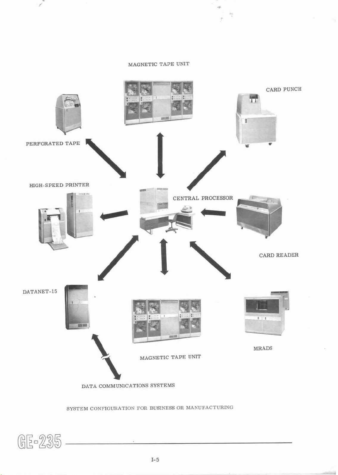
The basic system comprises a central processor with a six-microsecond core memory, card or
pe~forated tape input andoutput, electric typewriter input and output, and an operator's control con-
sole. The system configuration can readily be expanded to fit increasing information processing
needs. Equipment available includes:
--
Magnetic core memory
--
Card readers
Card punch
400 or 1000 cards per minute
--
100 or 300 cards per minute
4096-, 8192-, or 16,384-word capacity
Perforated tape reader
Perforated tape punch
Magnetic tape handlers
15,000/41,600 characters per second (at 200/555.5 bits per inch)
or
Mass random access data storage
34.4 million numeric digits per unit
High-speed printers
per minute,
Document handler
Data communication controllers
Floating point arithmetic capability (through the Auxiliary Arithmetic Unit)
An outstanding feature
system, allowing great flexibility in system configuration. Some typical system configurations for
various applications are shown on the following pages.
Programming aids available for the GE-235 include:
on/off line
--
250 or 1000 characters per second
--
110 characters per second
--
read and write 15,000 characters per second (at 200 bits per inch)
(MRADS)
--
900 alphanumeric lines per minute, on line, or 900 alphanumeric lines
--
reads and sorts 1200 documents per minute, on or off line
is
that up to ten input-output devices may be operated concurrently within the
--
18.8 million alphanumeric characters or up to
--
GECOM
be used with:
COBOL-type statements (specific, simplified English language statements)
ALGOL-type statements (algebraic expressions)
TABSOL (structured decision tables)
GECOM Report Writer (for programming business reports)
FORTRAN
ZOOM
--
WIZ
--
GAP
the general compiler, an all purpose, problem-oriented language program that may
--
a scientific compiler
--
a macroassembly system
a highly competent, one-pass algebraic compiler
a fast, compact, machine-oriented assembler
I- 2
Page 7
Standard report generators, sort/merge routines, BRIDGE (an ope rating system), GE-235/~~~ (a
major network analysis technique),
Thus, the GE-235 provides
economical solution of data processing and scientificproblems, and for potential growth in desired
areas. The characteristics and capabilities of this new member of the GE-200 Series are fully
described in this manual. However, detailedinformationfor operating and programming the system
is
in separate manuals on these subjects.
all
andother specializedprograms and routines are also available.
the tools for effective management decision-making, for fast and
I-
3
Page 8

1
CENTRALPROCESSOR
\I
CARD READER
HIGH-SPEED PRINTER
CARD PUNCH
SYSTEM CONFIGURATION FOR ENGINEERING CALCULATIONS OR REPORT GENERATION
HIGH- SPEED PRINTER
*
-
CARD PUNCH
fl"=-,
CENTRAL PROCESSOR
AND AUXILIARY
ARITHMETIC UNIT
MAGNETIC TAPE
UNIT
.
'
,
..
C..
.
.
.
CARDREADER
---my
(1000
CPM)
SYSTEM CONFIGURATION FOR SCIENTIFIC CALCULATIONS OR DATA RETRIEVAL AND REDUCTION
Page 9
rC
MAGNETIC TAPE UNIT
-
P.
.
.
11
rt
-.
.
-
,~
-
.
T+.
.
--
I
I
+*q!Fi
..
,?
..
_C--
.
-
CARD PUNCH
a@
I
1
-
---
..
PERFORATEDTAPE
HIGH-SPEED * PRINTER
DATANET-
15
--2
-!u7*-
z7-;
-
.
-
..
-~-'
d
-T
-
.
-.
*
/
CENTRAL PROCESSOR
4
..
I
-
.
'v:-???
(.
W
CARD READER
-.
I
.P
-1
DATA COMMUNICATIONS SYSTEMS
SYSTEM CONFIGURATION FOR BUSINESS OR MANUFACTURING
Page 10

HIGH-SPEED
PRINTER
MAGNETIC TAPE UNIT
CARD PUNCH
fW
CENTRAL PROCESSOR
DOCUMENTHANDLER
SYSTEM CONFIGURATION FOR BANKING
CARD READER
Page 11

PROGRAMMING AIDS
The General Electric Computer Department has developed a large library of programming aids to
help the programmer communicate with the GE-235 and simplify the task of producing useful results
from the computer.
generators and special programs designed to enhance the use of the GE-235 information processing
system.
This section describes some of the available programming tools: compilers,
GECOM,
The General Compiler (GECOM) System introduces a fresh, versatile approach to computer communication. This exclusive General Electric product makes available in one package both proved
and newly developed programming techniques. GECOM accepts many languages, so problem statements may be written in familiar terminology. The source languages available to the General
Compiler are broad and comprehensive.
GECOM will process English language sentences (COBOL-type statements), algebraic expressions
(ALGOL-type statements), structured decision tables
ation.
combination of the language features for any specificprogram run. Because the machine coding
derived directly from the logic of the problem statement, program check-out on the GE-235 may be
done at the logic level.
Because GECOM problems are written in familiar languages, they can be more easily read and
understood.
approach allows the user to accommodate the more important common coding languages and still
incorporate later changes conveniently. Several distinct advantages over manual programming
methods can be realized.
GECOM automatically produces a documented record of the program it produces. A permanent
-
record of the program, in its original source language form and with a detailed listing of its transformation to machine instructions,
THE
The user may select only that portion of the system applicable to his needs, using any
GENERAL COMPILER
(TABSOL), and a language for report gener-
is
In addition, program format provides a high degree of standardization. The selected
is
available for reference, revision, or augmentation.
Because plans call for implementing GECOM on the General Electric family of general-purpose
computers, programming conversion costs are reduced as installationsoutgrow their present com-
puter equipment.
Using familiar language sharply reduces personnel training time and expense. Manual coding
eliminated and debugging cut to a minimum. ~hus, a machine program may be produced quickly and
efficiently.
COBOL came into being as a result of a conference on Data Systems Languages sponsored by the
U. S. Department of Defense. Computer manufacturers and users developed the language called
COBOL
languages.
computers. The language first available with the General Compiler
(Common Business griented Language) to achieve standardization of data processing
COBO~
reduces progra&ing effort and achieves a more effective utilization of
is
based primarily on COBOL,
is
Page 12
which satisfies the needs of the broadest spectrum of data processing applications. COBOL is so
close to English syntax that it can easily be read and understood by management, systems, and
accounting personnel. As a result, close coordination between management and computer application is both practical and efficient.
is
COBOL
well suited to creating and processing information contained in data files.
In contrast,
ALGOL provides an excellent means for expressing the mathematics and logic associated with
scientific applications.
ALGOL was developed by an international group prompted by a growing interest in a standardized
notation for numerical methods for computers.
ALGOL
(ALGOrithmic Language) has proved to be far superior to any of its predecessors and has
enjoyed the first widespread acceptance and respect accorded a computer language. ALGOL notations are gaining acceptance internationally in numerical methods, text-books and university
classes.
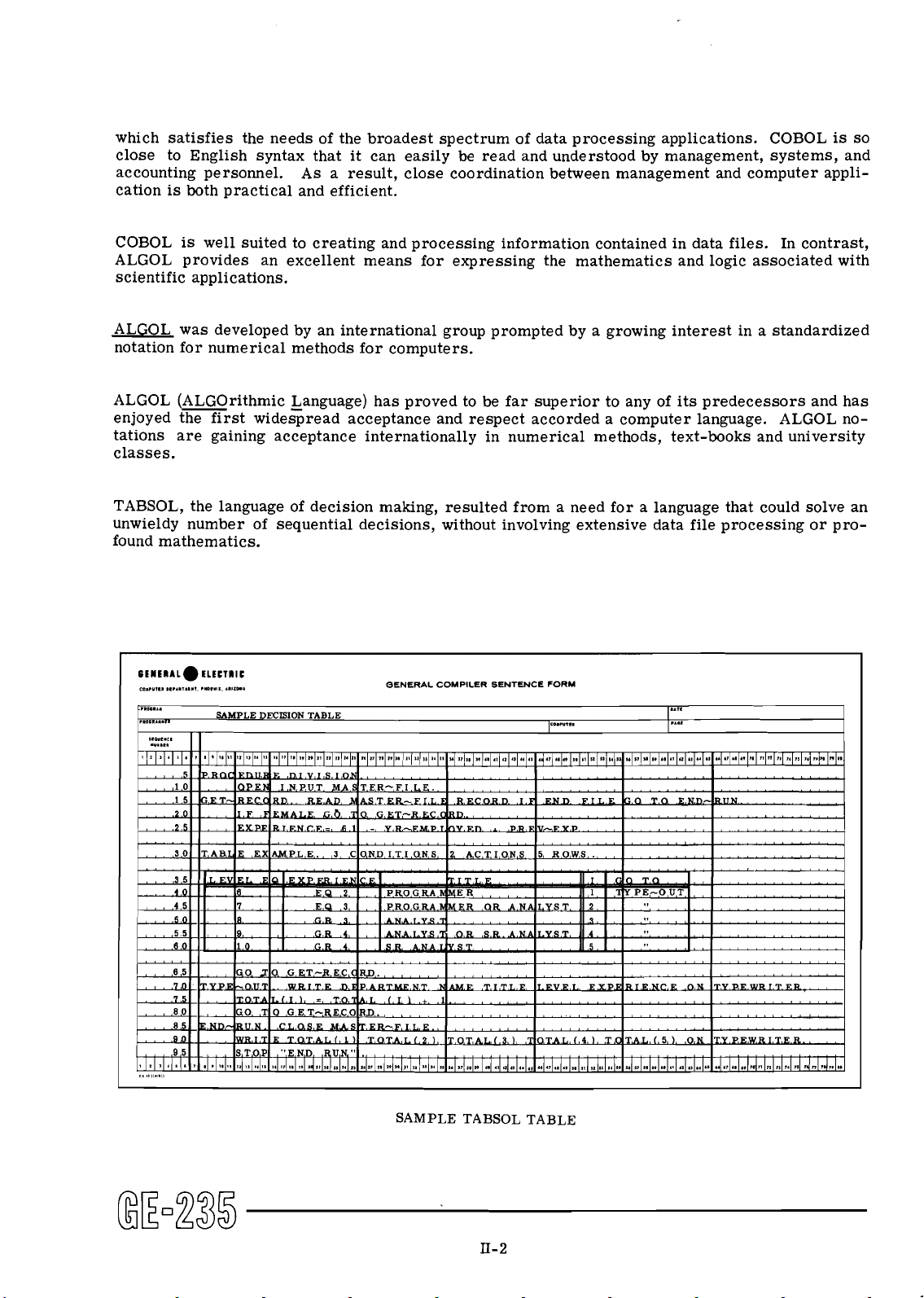
TABSOL, the language of decision making, resulted from a need for a language that could solve an
unwieldy number of sequential decisions, without involving extensive data file processing or pro-
found mathematics.
CEHERAL~
C~.,",,.
.1...,.
ELECTIIC
1.7.
.0,",1.
A.110..
OENERAL COMPILER SENTENCE FORM
c.
,3,,.,,,,
SAMPLE TABSOL TABLE
Page 13
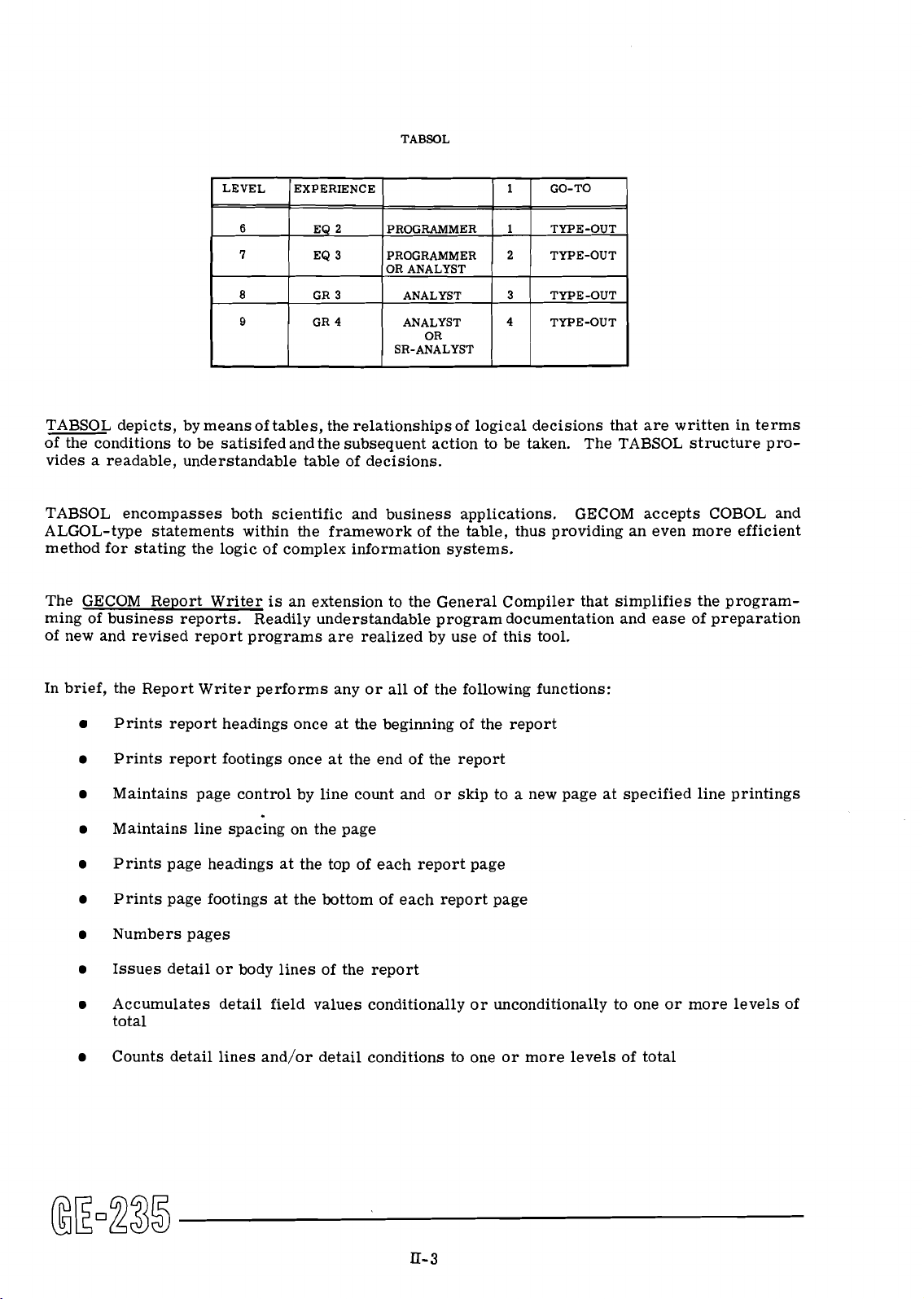
TABSOL depicts, by means of tables, the relationships of logical decisions that are written in terms
of the conditions to be satisifedandthe subsequent action to be taken. The
vides a readable, understandable table of decisions.
TABSOL structure pro-
TABSOL encompasses both scientific and business applications.
ALGOL-type statements within the framework of the table, thus providing an even more efficient
method for stating the logic of complex information systems.
The GECOM Report Writer
ming of business reports. Readily understandable program documentation and ease of preparation
of new and revised report
In brief, the Report Writer performs any or all of the following functions:
Prints report headings once at the beginning of the report
Prints report footings once at the end of the report
Maintains page control by line count and or skip to a new page at specified line printings
Maintains line spacing on the page
Prints page headings at the top of each report page
Prints page footings at the bottom of each report page
Numbers pages
Issues detail or body lines of the report
is
an extension to the General Compiler that simplifies the program-
are realized by use of this tool.
GECOM accepts COBOL and
Accumulates detail field values conditionally or unconditionally to one or more levels of
total
Counts detail lines and/or detail conditions to one or more levels of total
Page 14
Detects control breaks at one or more levels so as to:
a. Control the tabulation procedure
b. Issue logical control totals
c. Issue logical control headings
Edits data fields for reporting (for example, comma, decimal point, and dollar-sign
insertion and zero suppression)
The COBOL-61 to GECOM Translator converts programs described in COBOL-61 language into
language acceptable to GECOM. The source language of the basic compiler is based in part on
COBOL-60. The translator enablesGECOM toprovide for additional functions defined in COBOL-61
specifications.
FORTRAN
FORTRAN
Using this compiler with the GE-235, a source program written in the language of FORTRAN
scientific compiler, will produce an assembled program ready for use.
FORTRAN II Compiler With Card Input-Output
This compiler will compile a FORTRAN I1 source program on a GE-235 system with a minimum
input-output configuration. The full FORTRAN language
(magnetic tape operations, for example, are omitted).
ZOOM
Simplicity and flexibility of coding are principal features of the macroassembler called ZOOM (in
some respects a compiler). The simplicity of ZOOM coding is illustrated by the fact that the programmer writes algebraic expressions with such ordinary symbols as the plus, minus, and equal
signs. Since they are easily read, the expressions are easily and quickly checked for errors.
ZOOM translates these algebraic expressions into near optimum GAP coding. To the programmer
who has a working knowledge of GAP,
programs and produces near optimum object programs. Input
of GAP coding and ZOOM statements; output can be punched cards, magnetic tape, or printer
listings.
II
Compiler
II,
is
not implemented in this compiler
ZOOM allows for more condensed and readable symbolic
is
punched cards with combinations
a
Engineers and other users of the GE-235 who are not primarily programmers will find the WIZ
System a simple, easy-to-use algebraic compiler. The compiler translates source programs
written in the simple WIZ language, usingordinary mathematical symbols, into GE-235 object pro-
grams ready to run. WIZ produces GE-235 instructions on cards at a rate of 500 to 700 instructions per minute. WIZ makes iteasyfor the user to perform either simple or complex calculations
and print the results in edited form.
Page 15

WIZ works with both floating point and fixed point numbers and handles typical algebraic and
trigonometric problems quickly and easily. Modification I permits use of paper tape as well as
punched cards. Use of the optional
time of the object program.
AAU with the WIZ System significantly decreases the run
GAP, THE GENERAL ASSEMBLY PROGRAM
The General Assembly Program allows the programmer to write instructions for the GE-235 computer in symbolic notation rather than in the absolute code of the computer. Mnemonic codes for
each instruction are carefully chosen to provide significance to the user. Memory addresses may
be
assigned by using decimal notation or by using symbolic notation chosen for maximum convenience to the particular program or programmer. To extend the use of the General Assembly
Program the programmer can call on various subroutines (described below) as required by the
program. The General Assembly Program also provides facility for assembling of programs in
either absolute or relocatable form.
A wide range of assembler (pseudo) operations are available as follows:
ALF
BSS The BSS
DDC
DEC
EJT
END
EQO
EQU
FDC
LOC This operation performs the same function as the ORG operation but the contents are
LST
The ALF
This
This is used to enter a single-word decimal constant in the object program.
This operation causes the printer to slew the GAP listing paper to the top of the following
page.
The END
Performs the same function as the EQU operation but the operand is assumed to be an
octal number.
Used to over-rule the normal memory assignment performed by the assembly program.
This
scale
number.
assumed to be in octal form.
This pseudo-operation may be used to start the listing again after it has been suppressed
by the NLS.
is
used to enter an alphanumeric constant in the program.
is
used to reserve a block of memory storage.
is
used to enter a double-word decimal constant in the object program.
(~nd of Program) indicates the end of the program to be assembled.
is
used to enter a floatingpointdecimal constant in the object program. If no binary
is
specified, determines the binary scale and yields a normalized floating point
MAL
NAL
This pseudo-operation can be used to specify from
on one card.
A/N
This pseudo-instruction causes any
the 2's complement form.
constant or group of constants to be assembled in
1
to 9 words of alphanumeric constants
Page 16

NAM
Permits a program name to be printed at the top of each page of the GAP listing.
NLS
OC T
ORG
PAL
REM
SBR
SEQ
TCD
ZXX
Suppresses listing of the object program during assembly.
The OCT converts up to seven octal digits into a binary equivalent.
ORG (Origin)
This pseudo-operation can be used to specify from
is
used to indicate the location of the first instruction of the program.
1
to 9 words of alphanumeric constants
on one card. The last word generated will have the sign set to terminate a print line.
The pseudo-operation PLD will cause the assembly program to punch loader cards. When
the PLD pseudo-operation is encountered, all cards from that point to the end of the assembly will be punched in loader format.
The REM programmer's remarks immediately following are not processed by the assembly
but they do appear on the final program listing.
is
This pseudo-operation
used to call a specified subroutine master tape during assembly.
Checks the sequence number of each card against the sequence number of the previous
card.
Generates an instruction that transfers control to the location specified in the operand
field, at execution time; however, does not indicate end of assembly.
The ZXX pseudo-operation is used to set the operation bits of the assembled instruction to
any desired configuration. The operand can be decimal or symbolic, and indexing
is
optional. In use, a Z is placed in column 8 with the two octal digits (XX) desired as an
9
and
operation code in columns
10.
SAMPLE GAP CODING
Page 17

SUBROUTINES, SERVICE ROUTINES AND BRIDGE II
Subroutines
Subroutines are designed to handle, manipulate, move, or sort information within the computer
memory. Some of the important routines accomplish the following:
a
Conversion of data from one radix to another (octal, binary; BCD)
a
Word replacement
a
Internal memory sort
To solve problems in scientific areas, mathematical routines are available to calculate complex
functions and mathematical procedures such as:
Sine-cosine, square root, arctangent, exponential, and logarithm
Matrix transposition, inversion
a
Scalar multiplication
a
Linear simultaneous equations
a
Multiple regression
a
Roots of a polynomial
a
Least squares polynomial fit
a
Linear programming
Service Routines
The main functions of service routines are to assist in debugging programs and in simplifying oper-
ating procedures.
These routines have been prepared in symbolic and/or object program form.
Service routines to perform tasks such as the following are available:
a
Reset memory
Dump memory to cards, magnetic tape, paper tape, or printer
a
Load programs into memory
a
Trace programs
a
Compare, correct, and print out contents of tape
a
Correct cards
Page 18
Scan memory
Convert, analyze, and relativize card decks
Reproduce cards or print out contents
Bridge
Bridge
by the programmer, Bridge
The functions of Bridge
execution. For installations that have a steady work load, use of Bridge
SIMULATORS AND GENERATORS
II
11
is
a tape maintenance and run sequencing program. Upon the use of simple instructions
11
provides such functions as:
Run collection and sequencing from cards or tape
Tape correction of binary or symbolic programs
Dating of magnetic tape, using either date created or current date
Blocking of tape records
Provisionof run-to-runlinkage
Provision of altering run sequencing
Combining of runs with subroutine or relocatable sections
Provision for loading priority programs for use with API
I1 are directed by control cards that establish the run sequence for run
I1 reduces over-all time.
Forward
The Forward Sort and Merge Generator produces tailored card or tape programs to efficiently sort
and merge GE-235 data files, The sorts and merges are tailored at generation time according to
descriptive parameters written by the user. Extensive options that allow for use of GAP coding
enable users to attain complete flexibility in data format and selection and to utilize
media other than tape.
IBM-650 Simulator
The IBM-650 Simulator accepts IBM-650 System programs
the required routines to simulate the IBM-650 computer commands, and produces the same results
and outputs as the IBM-650 computer. An existing IBM-650 program need not be written in GE-235
language in order to run on the GE-235 computer.
Sort/Merge Generator
input/output
anddata as input, selects and executes
Page 19

Potential users of the GE-235 who have the IBM-650 computer can make a smooth transition to the
GE system through the use of simulators provided by General Electric.
The simulator program achieves the following objectives without loss of accuracy or flexibility:
Simulates the basic IBM-650 System, with 2000 words of drum memory, one 533 card
reader, and punch with alphabetic device.
An extended version provides the capability of
core storage, index registers, floating point, and magnetic tapes. The simulator program
runs on the GE-235, with
atleast 8192words of memory, card reader and card punch, and
typewriter.
Control cards preceding the IBM-650 program deck define the IBM-650 plugboard wiring
and console switch settings.
Can be modified to include other IBM-650 configurations or features with a minimum of
is
programming effort. Documentation
detailed and complete so that features peculiar to
certain applications may be readily incorporated.
LGP-30 Simulator
The LGP-30 Simulator executes the Royal
McBee LGP-30 system instructions in the GE-235 and
produces essentially the same results and outputs as that computer.
SPECIALIZED PROGRAMS
Special needs of computer users are filledby specialized programs such as the text searching system and the
GE-235/cP~ program. Other programs are tailored to needs of a specific industry
or user.
The Text Searching System
The Text Searching System permits retrieval of information from texts.
The System consists of
three principal programs. One converts texts (written in a natural or artificial language) into a
form suitable for searching. A second program compiles programs to search the texts for
requested symbol occurrences. The third program executes the compiled programs to search
converted texts and announce the search results.
The
GE-235/Cp~ program adapts a major network analysis technique to the GE-235. Complex
projects (such as new product introduction, large constructionprojects, and assembly-line planning)
consisting of as many as 2100 activities and
1000 events can be analyzed by the GE-235 in minutes.
Alternate schedules with optimum time and cost data, or other major project parameters, are
produced as a printed output. The
least an 8K memory,
4
magnetic tape handlers, a card reader, and a printer.
GE-235/~~~ program can be used with GE systems having at
Page 20
BankPac
A
series of generalized programs, called BankPac, have been tailored to the needs of commercial
banks. General Electric prepares broad programs to do such jobs as updating and maintaining
files, issuing reports,
functions. The user can readily add desired detailed programs. BankPac program will cover
demand deposit accounting, installment loans, savings accounts, transit items, and personal trusts.
making customer statements, and the handling of many other normal banking
Electric Utility Routines
Groups of Electric Utility Routines were tailored to needs of individual utility companies. These
programs are designed to compute load flow, optimal loading, load duration, gas flow and pressure,
and short circuit conditions.
Page 21

SYSTEM CONTROL OF
INPUT-OUTPUT PERIPHERAL DEVICES
In a GE-235 system up to ten input-output (I/o) devices of various types may operate simultane-
ously with the central processor and with each other. This truly active configuration is extremely
flexible and efficient; it is capable of a maximum throughput of 55, 000 20-bit words per second,
plus card reading,
per second, plus card reading, card punching and printing, by the addition of optional dual access
1/0 controller selector channels.
This performance is the result of two significant design concepts:
Each 1/O device controls itself and executes its own 1/0 commands.
All
central processor have access to memory on a time-sharing basis.
card punching and printing. The throughput may be doubled to 110, 000 words
I/O
devices (with exception of perforated tape reader/punch and typewriter) and the
INDEPENDENT-CONTROL OF
The
individual operation of each 1/0 device is determined by the controller through which it
attached to the system. The controller receives the commands appropriate to it (such commands
as to start,
these commands without further instruction.
central processor
stop, edit data, and rewind tape are typical) from the central processor and executes
is
free to continue with the succeeding item in the program.
TIME-SHARIIVG OF MEMORY ACCESS BY
Orderly and efficient time-sharing of memory access among the central processor and 1/O
devices of the GE-235
Allowing only one system element to have access to memory at one time.
Allowing each element access to memory on a priority schedule when it needs it and
causing
These conditions are satisfied in the GE-235 by the built-in priority control logic. The success
of this feature, in fact, accounts for the high efficiency and capacity of the system and the simultaneity of operation of
is
ensured by:
it
to relinquish access when it does not.
its
Garious elements.
1/0
DEVICES
Thus, having given a command to a controller, the
1/0
DEVICES
Priority Control and Time-Sharing
The GE-235 priority control feature is shown schematically in the accompanying block diagram.
For the numbered channels shown on the diagram, descending priority is from left to right (from
0 to
6).
The channel assigned to a particular 1/0 device depends upon its information transfer
-
that
is,
rate
its memory access requirements.
is
For
example, a high-speed printer has a lower priority requirement than a magnetic tape unit,
since a tape controller cannot wait as long for access as a printer controller can without causing
timing errors. If the printer had the higher priority, it could possibly monopolize access to
III-
1
Page 22
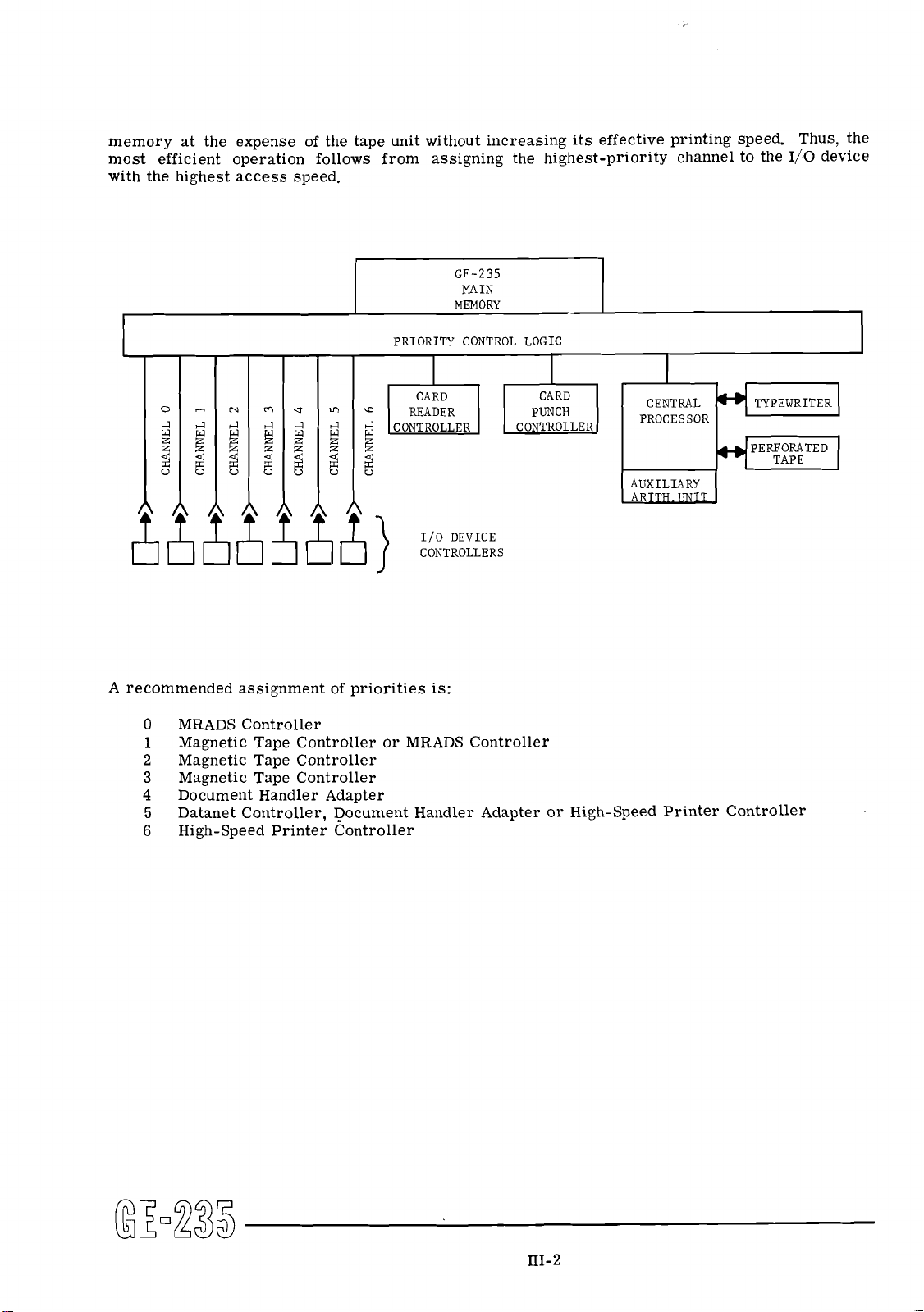
memory at the expense of the tape unit without increasing its effective printing speed. Thus, the
I/O
most efficient operation follows from assigning the highest-priority channel to the
device
with the highest access speed.
GE-235
MAIN
1
L
o
rlrl
N
m
e
rl
vr
a2."2E
gaaa
U
PRIORITY CONTROL LOGIC
a
rl
CARD
READER
,CONTROLLER
A recommended assignment of priorities is:
0
MRADS Controller
Magnetic Tape Controller or MRADS Controller
1
2
Magnetic Tape Controller
3
Magnetic Tape Controller
4
Document Handler Adapter
Datanet Controller, Document Handler Adapter or High-Speed Printer Controller
5
6 High-Speed Printer Controller
CARD
PUNCH
CONTROLLER
I
CENTRAL
PROCESSOR
Page 23

Examples of Time-Sharing
Three examples of GE-235 equipment configurations are shown below, with the relative amounts
I/O
of time consumed in each case by
activity and internal computation.
a
Example
Read cards at 400 cards per minute
Read magnetic tape at 15,000 characters
per second (500-character record)
Print at 900 lines per minute (edited)
Total
Percent of total time left for computing:
a
Example
Read cards at 400 cards per minute
Mass random access data storage (read
and write cycle at 200 milliseconds)
Print at 900 lines per minute (edited)
Total
Percent of total time left for computing:
a
Example
High-speed card reading at 850 cards per minute
Read magnetic tape at 41,600 characters per
second (500-character record) 4.2
Write magnetic tape at 41,600 characters per
second (500-character record) 4.2
Print at 900 lines per minute (edited)
A
B
C
Percent of Total Time
96.9*
98.6*
.7
.7
Total
Percent of total time left for computing:
*
Since execution of many instructions does not require access to memory, actual computing
time may range upward from the amount shown.
90.2*
Overall Effect of Time-Sharing
The overall effect of the GE-235 time-sharing arrangement is to create the most efficient balance
I/O
between
operations and internal computation, regardless of the type of application.
Page 24

PERIPHERAL SWITCH CONTROL UNIT
The Peripheral Switch Control Unit
many as seven 1/0 device controllers between two GE-200 Series systems. Any
normally connected to one of the numbered priority control channels may be switched by this unit.
This switching capability permits optimum utilization of all peripheral equipment for multiple
system operation.
The heart of the unit is the switch control console (see the accompanying illustration). The
console is
console performs two functions: 1) assigns each controller to the desired central processor
and 2) assigns the selected priority to each 1/0 device.
Two lighted pushbuttons are associated with each 1/0 device--one on the left of the panel
(SYSTEM
Separating each pair of SELECT buttons
the priority level of the associated 1/0 device. Additional circuitry actuates one of the ADDRESS
SELECT ERROR indicators if more than one controller
one system. A vertical column of eight numbered panel indicators marked SELECTED ADDRESS
also appears on each side of the panel.
on each system.
connected to each
1
-
SELECT PERIPHERAL) and one on the right (SYSTEM
is
an optional feature that makes possible the switching of as
I/O device
1/O device to be switched and to the two central processors. The
2
-
SELECT PERIPHERAL).
is
arow of ADDRESS SELECTION buttons for determining
is
switched to the same priority level on
These indicators show which priority levels are in use
1/0 DEVICE SWITCH CONTROL UNIT CONSOLE PANEL
Page 25
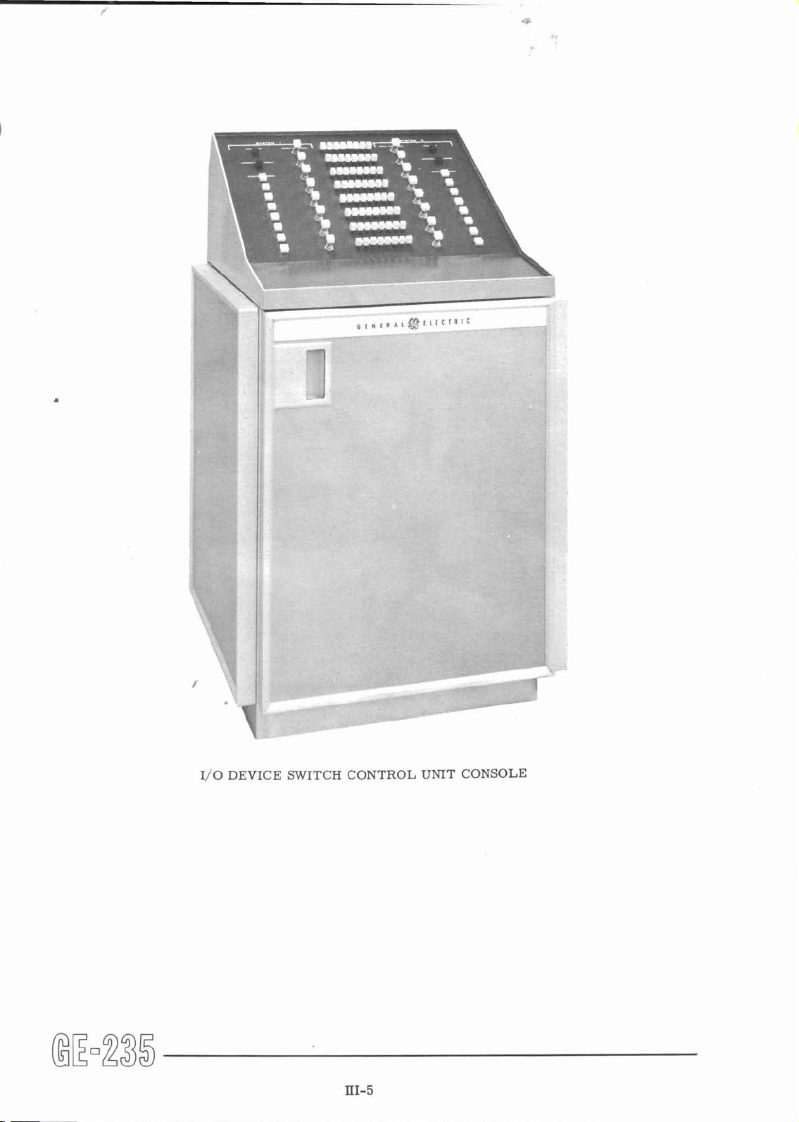
110 DEVICE SWITCH CONTROL
UNIT
CONSOLE
Page 26

CENTRAL PROCESSOR
Frr-
*
-
transistorized, single address, general purpose digital computer.
a
accepts and p/rocesses information from punched cards, magnetic tape, perforated tape,
magnetic ink character recognition equipment,
communications systems and other peripheral equipment.
provides output to magnetic tape, punched cards, perforated tape, high speed printer,
mass random access data storage, data communications systems and other output media.
Control Console
a
provides for complete operator control and communication with the system.
displays contents of the significant registers and provides control signals to the operator
for the effective monitoring of system operations.
mass random access data storage, data
IV-
1
Page 27

Console Typewriter
accepts instructions from the operator.
a
prints instructions to the operator.
a
monitors system operations.
a
prints direct output from the central processor.
MAGNETIC CORE MEMORY
The memory portion of the Central Processor is the immediate-access storage element for the
GE-235 system. Both the data to be processed and the controlling instructions are held in
memory and are called for by the control unit as required.
The memory is composed of magnetic cores
storing one unit of information, referred to as a bit. The basic unit of memory storage is the
--
"word"
address.
The size of the basic memory is 4096 words. The memory design allows for an expansion to an
8192-word memory or to a 16,384-word memory without the necessity of expensive retrofits.
The 16,384-word memory is divided into two groups of 8192 words each, referred to as the upper
bank and the lower bank.
Minimum instruction word access and execution time is 6 microseconds.
to or from memory, including the instruction word time, is accomplished in 12 microseconds;
a double word transfer is made in 18 microseconds.
are made in one-word parallel form; that is, the word bits are transferred simultaneously.
Internal
ferred to memory, and by recomputing and verifying that parity bit when the word is read from
memory. The effect of a
console
each word consisting of 20 bits plus a parity check bit. Each word has its own unique
checking is accomplished by generating and storing a parity bit when a word is trans-
puity error may be controlled to meet the needs of the application by
STOP/RUN switch operation.
.050 inch in diameter; each core is capable of
A
data word transfer
The transfer of words to and from memory
WORD FORMATS
The GE-235 can process data in either binary or alphanumeric form. This feature permits both
modes of operation to take advantage of the particular characteristics of a given application.
Alphanumeric (BCD) Words
When cards punched in Hollerith code are used as computer input, the information contained in
each
of the 80 columns is automatically converted into a six-bit binary-coded-decimal (BCD)
character. Thus, 3 alphanumeric characters occupy 18 of the 20 bit positions of an alphanumeric
Page 28

data word. Double length word operations permit the automatic handling of six alphanumeric
characters with a single instruction. These convenientword sizes eliminate the need for elaborate
partial word facility. Information must be in the BCD format prior to printing or typing.
The word below illustrates
how 3 random characters are represented in a six-bit (BCD) format
within one word:
The table below illustrates the range of alphanumeric characters which can be represented within
any six bit positions within any word of storage:
Alphanumeric Character
Zone
Bits Numeric Bits
A,
A
1
-+v-v-Y-w--vYv
0000 0001 0010 0011 0100 0101 0110 0111 1000 1001 1011 1100 1101 1110
GE-235
Alphanumeric Characters
Binary
A
binary data word consists of
Words
19
bits plus the sign bit. For example, the decimal number
+49
is represented in binary form as:
Negative binary numbers are expressed in 2's complement form. For example, the decimal
-10
number
is represented in binary form as:
4
1
=
-
(minus)
IV-
3
Page 29

A 20-bit word can accommodate a range of decimal values from -524,288 to +524,287, sometimes
referred to as 5-1/2 decimal digits. Double length word operations permit the efficient processing of decimal values between
associated with representing numeric data in the true binary format are:
Memory storage efficiency.
An effective increase in the rate with which numeric data can be transferred to and from
magnetic tape.
Increased speed of arithmetic and data handling operations.
+274,877,906,943 and -274,877,906,944. The advantages
Binary and BCD information may be intermixed in memory so as
mode of representing each field in each application, Subroutines are provided to convert numeric
data from BCD to binary, or vice-versa.
to provide the most efficient
Decimal Arithmetic
An optional Decimal Arithmetic feature of the GE-235 provides a decimal add and subtract
capability without requiring BCD to binary conversion. These arithmetic operations can be
performed on single decimal words of 3 digits or on double length decimal words of 6 digits.
Automatic carry is provided for larger fields.
numbers
+368 and +I5896 would appear in memory.
The examples below illustrate how the decimal
Floating Point Arithmetic
The GE-235 Auxiljary ~ritimetic Unit can be used to advantage in scientific and engineering
applications where numerous floating point or double precision arithmetic calculations are required. The logic of the AAU performs double precision fixed point and floating point arithmetic
more efficiently than is possible when using mathematical subroutines. However, subroutines
may be preferable when floating point arithmetic is done on a limited basis.
Three
floating
subtraction, multiplication, and division may be done under any of the three modes of operation.
All arithmetic is performed in binary mode.
modes of calculation may be performed by the Auxiliary Arithmetic Unit: unnormalized
point, normalized floating point, and fixed point double precision operations. Addition,
Page 30

During floating point calculations, the data to be operated upon by the internal logic of the
A
comes
from the main memory of the Central Processor.
floating point number occupies two
words of memory storage and assumes the following format:
Word One
AAU
Bits
Bits
0 1 2 3 4 5 6 7 8 9 10 11 12 13 14 15 16 17 18 19
Exponent
Se
Word Two
0 1 2 3 4 5 6 7 8 9 10 11 12 13 14 15 16 17 18 19
Se = Sign
Sm= Sign of Mantissa
of
Exponent
(0
(0
=
=
plus;
plus;
Mantissa
1
=
minus)
1
=
minus)
The binary point is assumed to be placed before the mantissa. This format produces a binary
number with a 30-bit mantissa and a binaryexponent range of -256 to
equal to a decimal format of a 9-digit mantissa and a decimal exponent range of -76 to
+255. This is approximately
+76. The
use of two words allows one of the sign positions to be applied to the exponent which, in turn,
allows the use of the full range of the exponent.
The word format for fixed point double precision words in memory
Word One
0
Bits
14
'+
19
is
as follows:
S
=
Sign of Word One
S
Fixed Point Double Word
0
Bits
S = Sign of Word Two
lp-lg
Word Two
is
the Sign of
Page 31

Instruction Words
With the exception of certain peripheral equipment operations, a GE-235 instruction is a single-
address word consisting of 20 bits. Except for branching operations, instructions are executed
sequentially;
the reading of the next instruction from memory occurs after the execution of the
current instruction.
The basic format of the instruction word
Bits
0
DO THIS
Bits
0
Opera tion
Code
is:
4 5 6 7
X
X
WITH DATA LOCATED HERE
4567
X X
19
19
Operand Address
Bits 0 through 4 designate the operation to be performed, bits 5 and 6 indicate whether the instruction is to be automatically modified (indexed), and bits
7
through
19
indicate the operand
address.
Because the
five bit positions allowed in the instruction word for the operation code can define
only 32 operations, additional bit positions are required to define the more than 300 instructions
in the repertoire of the GE-235.
This is achieved by using bit positions in the operand address
field for instructions that require only a limited portion of that field.
REGISTERS
With the exception of shift instructions, all information transfers between Central Processor
registers, between the registers and memory, and between the registers and the adder occur in
parallel. That is, all 20 bits comprising words in transit or being operated upon arithmetically
are transferred at the same time.
A
Register
The
A
register is a 20-bit register that serves as the accumulator for the Central Processor.
It performs this function by holding:
The augend during addition.
The sum after addition.
The minuend during subtraction.
IV-
6
Page 32

The result after subtraction.
The most significant half of the product after multiplication.
The most significant half of the dividend before division.
The quotient after division.
The most significant half of a double wordafter the execution of all double length instructions.
The word to be shifted during various shift instructions.
The word transferred to or from memory or another register or to be modified in some way
during the execution of various data transfer instructions.
The word on which tests are performed during the execution of branch instructions.
Q
Register
The
Q
register
remainder after division and acts with the
is
a 20-bit register which holds the multiplier during multiplication and the
A
register to form a 38-bit (plus a sign bit) accumulator
during the execution of double word operations. When double word instructions are used, the
Q
least significant half of the double word is automatically transferred into the
the
A
register. Briefly, the functions of the Q register are:
register through
Holds the multiplier during multiplication.
Holds the least significant half of the product after multiplication.
Holds the least significant half of the dividend before division.
Holds the remainder after division.
Holds the least significant half of a double word after the execution of all double length
instructions.
N
Shifts in conjunction with the
N
Register
and A registers in special shift instructions.
The N register is a 6-bit register which is used as a single character (BCD) buffer between the
computer and the typewriter and the perforated paper tape reader and punch. Information
is
transferred directly between the N register and the A register.
I
Register
The I register is the instruction register. It contains the 20 bits of an instruction word during
execution of a computer command. While instructions are being processed, bits
0 through
indicate the operation to be performed and bits 5 and 6 control the indexing of instructions when
specified by the program. During the execution of instructions involving reading an operand
from memory (and after appropriate indexing has taken place), bits
through
19
contain the
5
memory location of the operand.
4
Page 33

Index
Words
Index words are locations in memory (0000, 0001, 0002, 0003) reserved for use as counters or
for the automatic modification of instructions in the
I
register when specified by the program.
Unlike GE-235 registers, the index words are integral parts of memory and not separate physical
storage devices.
index words.
128
An optional feature adds 31 index groups of
4
locations each, giving a total of
N
Register
GE-235 REGISTER RELATIONSHIPS - BLOCK DIAGRAM
Console typewriter
paper tape reader
and punch
Page 34

P
Counter
The P counter
is
a 15-bit sequence control counter that contains the memory address of the next
instruction to be executed. The contents of the P counter are incremented by one after the current
instruction has been selected from memory and placed in the
I
register, so that the P counter
normally indicates the address of the next instruction in sequence. The contents of the P counter
I
can be set from the
register during the execution of branching instructions specified by the pro-
gram.
M Register
The M register
memory and the Central Processor or peripheral equipment. When a word enters the
from the Central Processor or punched card equipment for recording in memory, a parity bit
is
a 21-bit register that acts as an input-output buffer between the magnetic core
M
register
is
computed and 21 bits are storedin memory. Peripheral controllers that are connected through the
numbered priority control channels generate a parity bit which
to the storage of the 21-bit word in memory. When a word
register, parity
is
again computed and the new parity bit is compared with the one already existing
is
checked in the M register prior
is
read from memory into the
M
to ensure accuracy of data transfers.
Adder
The adder of the Central Processor is a high-speed, parallel, binary adder network that executes
the calculations specified by the instruction code in the
I
register during arithmetic operations.
Real Time Clock
The Clock, or C register,
Central Processor, the C register is automatically incremented by
is
a 19-bit register (there is no sign bit). While power is applied to the
a
binary one every sixth of a
second. When the count reaches 518,400, the decimal equivalent of 24 hours in sixths of a second,
the C register
The real time
is
automatically reset on the next increment to all zeros and starts counting again.
clockis loadedfrom the A register, and its contents can be read by transferring them
to the A register. The clock can be set or read either by program or by manually inserted instructions.
AUXILIARY ARITHMETIC UNIT
The addition of the GE-235Auxiliary Arithmeticunit (AAU) extends the arithmetic capability of the
GE-235 system. This device, with built-in logic, facilitates floating point and double precision
arithmetic through its increased capacity and the speed with which it computes. The Auxiliary
Arithmetic Unit contains two 40-bit registers, AX and QX, which correspond functionally to the A
and
Q registers in the Central Processor.
and divide extremely large numbers
represented in either fixed or floating point format. At the
option of the programmer, the unit functions in three modes: normalized floating point,
Eighty bits permit the unit to add, subtract, multiply
unnormal-
ized floating point, and fixed point computations. Underflow and overflow conditions are checked
by means of programmed interrogation.
Page 35

The Auxiliary Arithmetic Unit is not a peripheraldevice; it is an extension of the basic arithmetic
unit of the Central Processor. All peripheral operations may occur concurrently with the use of
this device.
When data in the two-word floating point format enters the Auxiliary Arithmetic Unit, it is converted into one 40-bit word and stored in the AX register. (Number designations for bits in the
AAU start with number 1 rather than 0 as used in memory.) The word exists in the 40-bit AX
register as:
Bits
1
2
Se
Exponent Mantissa
Se = Sign of Exponent
Sm
=
9
10 20 21 22 40
Sign of Mantissa
Sm
Mantissa
The QX register is an extension of the AX register. It also consists of an eight bit exponent with
sign and a thirty bit mantissa with sign. The value of the exponent of the QX register
is
the value
of the AX register minus 30.
When data in the fixed point double precision format enters the Auxiliary Arithmetic Unit, the two
Y
+
1)
words from memory (Y and
are converted into one 40-bit word and stored in the AX
register. The word exists in the 40-bit AX register as:
Bits
1
2 20 21 22 40
S
S = Sign
Y
S
Y+l
An instruction for the Auxiliary Arithmetic Unit is contained in one 20-bit word identical to the
format of Central Processor instructions.
ADDRESS MODIFICATION (INDEXING)
The GE-235
achieved
is
capable of automatic address modification under program control. This is
through the use of the special index words in memory locations 0001, 0002, and 0003.
Memory location 0000 is not used for address modification, but it can operate as a counter.
Thirty-one additional index word groups are available as an optional feature.
tains four
used either as counters or for automatic address modification.
(groups are numbered
index words; the first word may be used as a counter, the other three words may be
The total of 32 index word groups
0 - 31), if included in the system, occupy memory locations 0000 through
Each group con-
0127. Any of these locations may be used for normal storage if not required for address modification in a program. Thus, the GE-235 features
total of
96
index words for the address modifi-
a
cation of instructions and a total of 128 index words which may be used as counters and incremented
and tested by special index word instructions.
Page 36

Bit positions 5 and 6 of an instruction word designate the index word to be used in modifying the
operand address portion of the instruction. Binary configurations select index words as follows:
01
=
location 0001, 10 = location 0002, and 11 = location 0003. Bits 00 in positions 5 and 6 indicate
that no modification is to be performed, If the additional 31 index word groups are available, an
instruction is provided to allow the selection of any one of the 32 groups at any point in the
program.
If
an instruction in the I register calls for automatic address modification, an extra word time
(6 microseconds) is required to accomplish the operation.
The sequence of events in an automatic address modification is:
The instruction to be executed is read into the I register.
Bits
5
through 19 of thedesignatedindexword and bits 7 through 19 of the I register are added
together and the
result replaces bits
5
through 19 of the I register. Bits 0 through 4 of the
I register are unchanged.
The modified instruction in the I register is executed.
The original instruction in memory is not changed.
INSTRUCTION REPERTOIRE
The descriptions on the following pages are those of instructions which may be completely executed
by the Central Processor without assistance from any of the other system units. Descriptions
associated with peripheral units may be obtainedelsewhere in the manual following the description
of each peripheral device. Instructions in this section have been grouped under the following
headings:
Data Transfer
Arithmetic
Shift
Branch
Address Modification
Auxiliary Arithmetic Unit
Real Time Clock
Each description gives the mnemonic operation code for the instruction and an indication of whether
a memory location
(Y)
or a constant
(K)
is
required in the operand address portion. Some instruc-
tions do not require an operand, so for these no entry will be found under the Operand Address
X
column. The letter
under the Index column indicates that the instruction can be indexed. Exe-
cution times are given in microseconds. The execution times include the fetching of the instruction
and data.
In all instructions which involve the bringing of a word from memory, the word in memory remains
unchanged. For most instructions involving the transfer of information from registers, the
condition of the register after execution
is
unchanged.
Page 37

FOR THE PURPOSES OF THIS MANUAL, THE DESCRIPTION OF EACH INSTRUCTION 1s
NECESSARILY ABBREVIATED. COMPLETE EXPLANATIONS WITH EXAMPLES MAY BE
IN
FOUND
THE GE-235 PROGRAMMING REFERENCE MANUAL.
Data Transfer
Mnemonic
Oper. Code Address
LDA Y X 12 LOAD A register with the contents of
DLD
STA Y
DST
Operand
Index Time
Word Microsec. Description
Y X 18 DOUBLE LENGTH LOAD registers A and
Y
contents of Y and
X
12 STORE A register contents into memory location Y.
X 18 DOUBLE LENGTH STORE contents of registers A
Q into Y and Y+1.
and
Y+1.
Y.
Q with the
MOV Y 24+12N MOVE a block of N words starting at memory lo-
cation Y into another area of memory. Register A
contains starting address of new area; register
Q
contains number of words to be moved (in 2's complement form). This instruction is an optional
feature.
ST0
18 STORE OPERAND ADDRESS field of register A in
the operand address field of Y.
ORY
EXT
18
OR A INTO Y byplacing a
A has a
1
bit in the corresponding position.
18 EXTRACT into A by placing a
wherever Y has a
1
1
bit in Y wherever register
0
bit in register A
bit in the corresponding position.
LD
Z
LDO
18 LOAD A FROM
Q
register
18 LOAD
into A.
Q
FROM A by transferring the contents of
register A into
Q by transferring the contents of
Q.
18 MOVE A TO Q and replace the contents of A with
zeros.
18
EXCHANGE A AND
of registers A and
Q by interchanging the contents
Q.
18 LOAD ZERO into all bit positions of register A.
18
LOAD ONE bit into 19th bit position of register A and
set the other bit positions to
0.
IV- 12
Page 38

Mnemonic
Operand
Oper. Code Address
LMO
Inex
Word Microsec.
7
Time
18
LOAD MINUS ONE into register A by setting all bit
positions to
18 COMPLEMENT register A by replacing each 1 bit
with
Description
1.
0
and each 0 bit with
1.
18
NEGATE A by replacing the contents of register A
with the 2's complement.
12 CHANGE SIGN of register A by replacing
position with
0
and a 0 bit in sign position with
NOP 18 NO OPERATION; next
Arithmetic
Mnemonic Operand Index Time
Oper. Code Address Word Microsec.
ADD
Y
-
X
12 ADD the contents of Y and register A algebraically;
Description
sum in A.
DAD
Y
X
18 DOUBLE LENGTH ADD the contents of Y and Y+l
A
and registers
18
ADD ONE (plus one) algebraically to the contents of
and Q algebraically; sum in A and Q.
register A.
X
X
18 SUBTRACT the contents of Y algebraically from the
A.
30
contents of register
DOUBLE LENGTH SUBTRACT the contents of Y and
Y+l algebraically from the contents of registers A
and
Q;
result in A and
instruction
Q.
1
is
executed.
bit in sign
1.
MPY
DVD
18
SUBTRACT ONE algebraically from the contents of
register A.
X
X
54-138 MULTIPLY the contents of Y algebraically by the
contents of register
gisters
A
and Q.
Q, placing the product in re-
156-174 DIVIDE the contents of registers A andQ algebraically
by the contents of Y, placing the quotient in A and the
remainder in Q.
IV- 13
Page 39

OPTIONAL DECIMAL ARITHMETIC
Mnemonic Operand
Oper. Code
SET
SET
ADD
DAD
ADO
SUB
DSU
Address
BINMODE
DECMODE
Y
Y
Index Time
Word Microsec.
-
X
X
X
X
12
12
12
18
18
18
30 DOUBLE DECIMAL SUBTRACT the contents of
SET BINARY MODE, permitting arithmetic instructions to operate in the binary mode as detailed above.
(When power
automatically in the binary mode.)
SET DECIMAL MODE, permitting arithmetic instruc-
tions to operate in the decimal mode as detailed below.
DECIMAL ADD the contents of
algebraically; sum in A.
DOUBLE DECIMAL ADD the contents of Y and
and registers A and Q algebraically; sum in A and
ADD ONE DECIMAL (plus one) algebraically to the
contents of register A.
DECIMAL SUBTRACT the contents of Y algebraically
from the contents of register A.
and
A and
Description
is
turned on, the computer will be set
Y
and register A
Y+l
algebraically from the contents of registers
Q;
result in A and
Q.
Y+l
Q.
Y
SBO
Shift
The shift instructions shift the contents of register A to the right or left serially either alone or
with the contents of the N and/or
two bit positions or less; six additional microseconds are required for each additional 3-bit shift
or fraction thereof.
Mnemonic Operand
Oper. Code
SRA
SRD
SLA
Address
K
K
K
Index
Word Microsec.
-
X
X
X
18
Q
registers. Twelve microseconds are required for a shift of
Tim
12+
12+
12+
SUBTRACT ONE DECIMAL algebraically from the
contents of register A.
Description
SHIFT RIGHT A. The contents of register A are
shifted right
SHIFT RIGHT DOUBLE. The contents of registers A
and
Q
shifting out of A into
SHIFT LEFT A. The contents of register A are
shifted left
K
places.
together are shifted right K places, with bits
Q.
K
places.
Page 40

Mnemonic Operand Index
Oper. Code
SLD K
~hdress Word
-
X
Time
Microsec.
12+
Description
SHIFT LEFT DOUBLE. The contents of registers A
and Q together are shifted left K places, with bits
shifting out of Q into A.
SCA
SCD
SAN
NAQ
NOR
12+
12+
12+
12+
12+
12+
18+
SHIFT CIRCULAR A. The contents of register A are
K
shifted
SHIFT CIRCULAR DOUBLE. The contents of registers
A and Q together are shifted K places to the right in a
circular fashion, with bits shifting out of A into Q and
out of Q into A.
SHIFT A AND N RIGHT. The contents of registers A
and N together are shifted K places to the right, with
bits shifting out of A into N.
SHIFT N AND A RIGHT. The contents of registers N
and A together are shifted K places to the right, with
bits shifting out of N into A.
SHIFT A INTO N AND Q. The contents of register A
are shifted K places to the right into both registers N
and Q.
SHIFT N, A, AND Q RIGHT. The contents of registers
N, A, and Q together are shifted Kplaces to the right.
NORMALIZE. The contents of registerA are normalized by shifting left and eliminating leading zeros up
to K places.
places to the right in a circular fashion.
DNO
Branch
Mnemonic
Oper. Code
BRU
SPB
Operand
Address
Y
Y
18+
Index Time
Word Microsec.
-
X
X
6
12
DOUBLE LENGTH NORMALIZE. The contents of
registers A and Q are normalized by
and the elimination of leading zeros in register A up
to K places.
BRANCH UNCONDITIONALLY. Control is transferred
to the instruction at memory location
STORE P AND BRANCH. The locationof this SPB instruction replaces the contents of index word X and
control
location Y.
is
then transferred to the instruction at memory
a
double shift left
Y.
IV-
15
Page 41

The following branch instructions test to determine whether a particular internal condition
or false.
false, the second sequential instruction is executed.
If the condition tested is true, the computer executes the next sequential instruction; if
is
true
Mnemonic
Oper. Code
BPL 12 BRANCH ON PLUS. Register A tested for plus sign.
BMI 12 BRANCH ON MINUS. Register A testedfor minus sign.
BZE 12 BRANCH ON ZERO. Register A tested for all zeros.
BNZ
BOV
BNO
BOD 12 BRANCH ON ODD. Register A tested for odd value.
BEV 12 BRANCH ON EVEN. Register A testedfor even value.
BPE
BPC
Operand
Address
Index Time
Word Microsec.
-
12 BRANCH ON NON-ZERO. Register A testedfor not all
12 BRANCH ON OVERFLOW. Overflow indicator tested
12 BRANCH ON NO OVERFLOW. Overflow indicator
12 BRANCH ON PARITY ERROR. Parity error indicator
12 BRANCH ON PARITY CORRECT. Parity error
Description
zeros.
for ON.
tested for OFF.
tested for ON.
indi-
cator tested for OFF.
CAB Y
(Optional feature)
DCB Y
(Optional feature)
X
X
12-24 COMPARE AND BRANCH. Register A compared alge-
braically with contents of Y. If contents of Y are
greater, the next instruction is executed; if contents of
Y and A are equal, the second sequential instruction is
executed; if contents of Yare less, the third sequential
instruction is executed.
12-24 DOUBLE COMPARE AND BRANCH. Registers A and
Q
together are compared algebraically with contents of
Y+1. Branching occurs in an analogous manner
Y and
to the CAB instruction above.
Page 42

Address Modification
Mnemonic Operand Index Time
Oper. Code Address Word Microsec.
-
18 INCREMENT X. The constant
Description
K
is
added absolutely
to the contents of index word X, and the result replaces the contents of X.
18
18
LDX
STX
SXG
Auxiliary Arithmetic Instructions
AAU instructions for floating point operations assume that the operands to be acted upon are
already in floating point format. The operands are put in floating point format by means of a
subroutine furnished for this purpose.
X 18 LOAD X. The contents of
X 18 STORE
12 INDEX GROUP SELECT. If additional index word
BRANCH IF X IS HIGH OR EQUAL. Contents of index
word X are tested for an equal to or greater than
condition. Branching follows the normal sequence of
branch instructions.
BRANCH IF X IS LOW. Contents of index word X are
tested
the normal sequence of branch instructions.
X.
in
groups are available, this instruction selects one of
the 32 possible groups.
particular group.
for a less than
X.
Y.
The contents of index word X are stored
K
condition. Branching follows
Y
are placed in index word
Y
(00 - 31) specifies the
K
Before giving an arithmetic instruction to the AAU it is necessary to set the mode of operation
by one of the following SET instructions:
Mnemonic Operand
Oper. Code Address
U
FLPOINT
NFLPOINT
FMPOINT
Index Time
Word Microsec.
-
6
6
6
Description
This instruction sets the format for unnormalized
floating point operations.
This instruction sets the format for normalized
floating point operations.
This instruction sets the format for double word
fixed point operations.
IY-17
Page 43

The mnemonics for the following AAU instructions consist of the normal three alphabetics plus
the tag A in GAP coding sheet column 20. For example, LAQ A moves the contents of the QX
register to the AX register in the
in the central processor.
AAU while LAQ without the A tag moves the contents of Q to A
Mnemonic
Oper. Code
LQA
The memory address
address modification, must be greater than 001
Mnemonic
Oper. Code
FLD
FST
Operand
Address
Ope rand Index Time
Address Word Microsec. Description
Y
Y
Index Time
Word Microsec.
-
6 LOAD AX FROM QX. The contents of register QX
are moved into AX. QX is unchanged.
6 MOVE AX TO QX.
moved into QX. AX
6 LOAD QX FROM AX. The contents of register AX
are moved into QX. AX is unchanged.
6 EXCHANGE AX AND QX. The contents of registers
AX
(Y)
designated in an AAU instruction, as it appears in the I register after
X 18 LOAD AAU. Contents of Y and
register AX.
X 18 STORE AAU. Contents of register AX are stored
into
Description
The contents of register AX are
is
cleared to zeros.
and QX are interchanged.
5.
Y
and
Y+1.
Y+l
are loaded into
FAD
Y
X
24-36 NORMALIZED FLOATING POINT ADD. The floating
point number in
the floating point number in register AX. The result
is in AX in normalized form.
24-30 UNNORMALIZED FLOATING POINT ADD. Same as
normalized floating point add except the result is
placed in registers AX and QX and may or may not
be in normalized form.
24 DOUBLE WORD
of
Y
and
Y+l
of register AX and the result
38 bit fixed point number.
Y
and
Y+l
is
added algebraically to
FIXED POINT ADD. The contents
are algebraically added to the contents
is
placed in AX as a
Page 44

Mnemonic
Oper. Code
Operand
Index Time
Address Word
Microsec.
FSU
FMP
NORMALIZED FLOATING POINT SUBTRACT. The
floating point number in Y and Y+l
is
subtracted
algebraically from the floating point number in register AX. The result
is
placed in AX in normalized
form.
UNNORMALIZED FLOATING POINT SUBTRACT.
Same as normalized floating point subtract except
the result
is
placed in registers AX and QX and may
or may not be in normalized form.
DOUBLE WORD FIXED POINT SUBTRACT. The
contents of
Y
and Y+l are algebraically subtracted
from the contents of register AX and the result is
placed in AX as a 38 bit fixed point number.
NORMALIZED FLOATING POINT MULTIPLY. The
floating point number in Y and Y+l is algebraically
multiplied by the floating point number in register
QX. The 60-bit product of the two mantissas is
normalized. The most significant half of the normalized product is stored with its exponent in AX;
the least significant half is stored in QX (the exponent
30 less than the floating point exponent in AX).
UNNORMALIZED FLOATING POINT MULTIPLY.
Same as normalized floating point multiply except
the result is placed in registers AX and QX and may
or may not be in normalized form.
DOUBLE WORD FIXED POINT MULTIPLY. The
contents of Y and
Y+l are algebraically multiplied by
the contents of register QX, giving a 76-bit product
4
and
of the product is stored with
the least significant half
identical sign bits. The most significant half
2
sign bits in AX, and
is
stored with 2 sign bits in
QX.
FDV
NORMALIZED FLOATING POINT DIVIDE. The
floating point number in registers AX and QX
is
algebraically divided by the floating point number in
Y
and Y+1. The normalized quotient
is
stored in AX,
and the remainder, which may or may not be nor-
is
malized,
stored in QX.
UNNORMALIZED FLOATING POINT DIVIDE. Same
as normalized floating point divide except the quotient
that is stored in AX may or may not be in normalized
form.
DOUBLE WORD FIXED POINT DIVIDE. The contents of registers AX and QX are divided by the
contents of Y and
Y+1. The quotient is stored in AX
and the remainder in QX.
IV- 19
!
Page 45

Mnemonic Operand
O~er. Code Address
BAR XXX
Index Time
Word Microsec.
-
Description
BRANCH ON AAU INTERROGATED CONDITIONS.
The BAR instruction interrogates the AAU for spe-
is
cific conditions. The condition tested
a mnemonic placed in the operand address field and
by
indicated
condition tested
next sequential instruction. If false, the second
sequential instruction
require a
XXX in the format given here. If the
is
true, the computer executes the
is
executed. BAR instructions
7
in GAP coding sheet column 20.
indicated
by
BAR
BAR
BAR
BAR
BAR
BAR
BAR
BAR
BAR
BPL
BMI
BZE
BNZ
BOV
BNO
BU F
BNU
BER
7
7
7
7
7
7
7
7
7
12 BRANCH ON AAU PLUS. Register AX
plus sign.
12 BRANCH ON AAU MINUS. Register AX
a minus sign.
12 BRANCH ON AAU ZERO. Register AX
all zeros.
12 BRANCH ON AAU NOT ZERO. Register AX
tested for not all zeros.
12 BRANCH ON AAU OVERFLOW. AAU
overflow indicator ON.
12 BRANCH ON AAU NO OVERFLOW. AAU
for overflow indicator OFF.
12 BRANCH ON AAU UNDERFLOW. AAU
underflow indicator ON.
12 BRANCH ON AAU NO UNDERFLOW. AAU
for underflow indicator OFF.
12 BRANCH ON AAU ERROR. The error indicator is
tested for ON.
is
tested for a
is
tested for
is
tested for
is
tested for
is
is
tested for
is
is
tested
tested
BAR
BAR
BAR
BAR
BAR
BNE
BOO
BON
BUO
BUN
7
7
7
7
7
12 BRANCH ON AAU NO ERROR. The error indicator
is
tested for OFF.
12 BRANCH ON OVERFLOW HOLD ON. AAU is tested
for overflow indicator ON.
12 BRANCH ON OVERFLOW HOLD NOT ON. AAU
tested for overflow indicator OFF.
12 BRANCH ON UNDERFLOW HOLD ON. AAU
for underflow hold indicator ON.
12 BRANCH ON UNDERFLOW HOLD NOT ON. AAU
tested for underflow hold indicator OFF.
is
is
tested
is
Page 46

Mnemonic
Oper. Code
Operand Index Time
Address Word
-
Microsec.
Description
ROV
RUN
RIN
6
RESET OVERFLOW HOLD. The overflow hold indi-
is
cator
6
RESET UNDERFLOW HOLD. The underflow hold
indicator
6
RESET INDICATORS. The underflow hold and overflow hold indicators are turned off.
turned off.
is
turned off.
Real Time Clock Instructions
Mnemonic Operand
Oper. Code
LAC
LCA
Address
Index Time
Word Microsec.
-
18
18
Description
The contents of register A are replaced by the contents
of register C and the sign of
1
Bit positions
register C.
through 19 of register A are placed in
registerA is set to zero.
CONTROL CONSOLE
The GE-235 Control Console provides the operator with the controls and indicators necessary for
direct manual and visual communication with the Central Processor. Basic alarm conditions are
clearly displayed to facilitate accurate operator corrective action. The detailed contents of
arithmetic, instruction and program counter registers are displayed. Changes or deletions of
instructions or data can be made through convenient toggle switches.
Automatic and manual control modes allow complete operator control of programs. In the auto-
matic mode, the computer executes instructions in the normal sequential manner. In the manual
mode, the computer executes instructions in a step-by-step procedure, going from one instruction
to the next under operator control.
The lower third of the console consists of the Control Panel which contains operating switches that
control Central Processor power, operating mode selection, alarm and register resetting, initial
program loading, and starting and stopping of computer operation.
is
The upper two-thirds of the Control Console
Switches. The Indicator Panel consists of display lights for the contents of the A,
and the P counter and for the location of the current selected index word group. Toggle switches
are provided to allow for the manual entry of information into the A register. In addition, various
alarm and ready status indicators that are essential for proper control are provided, as well as an
indicator showing the controller that is actively accessed at any given time. For Central Processors equipped with the optional AAU, additional AAU switches and indicators appear above the
standard indicator panel.
occupied by the Indicator Panel and Register Control
N
and I registers
Page 47

No00
6
000
66d
P
CYYUTLR
666
666
bc)6
o6
'I
6o
A
R15ET
6QQ QQQ QQQ @Q@ QQQ QQQ QQQ
660 666
OPERA,#OM
1
,No,X
I
CONTROL
66iS
dbi4
CONSOLE
666
666
LDDREIl
666
666
b66
666
I
Page 48

INPUT/OUTPUT TYPEWRITER
The GE-235 Input/~utput Typewriter can transmit input data to the Central Processor from the keyboard while simultaneously printing the data. Communication with the Central Processor during
is
both input and output operations
programmed single-character (BCD) operations. Output
through the N register. All input and output operations are
is
at the rate of 15 characters per second.
The typewriter keyboard has
writer characters include:
Functions that can be programmed are:
Space
Carriage Return
Tabulation
Print Red
Print Black
Ignore
Index
44datakeys, a space bar and standard functional control keys. Type-
ALPHABETICS A THROUGH
NUMERIC DIGITS 0 THROUGH
SPECIAL CHARACTERS AS FOLLOWS:
Z
9
Console
Mnemonic Operand
Oper. Code
RCS
TON
TYP
KON
And
Typewriter Instructions
Address Word Microsec.
Index Time
-
12 READ CONTROL SWITCHES, Each of the 20 console
12 TYPEWRITER ON. The typewriter
12
12 KEYBOARD ON. The typewriter input keyboard
Description
control switches for register
1
switch is down (ON), a
sponding position of A.
nected to the N register.
TYPE. If the typewriter
is
the N register
typed.
bit
is
ON, one BCD character in
A
are examined.
is
placed in the corre-
is
logically con-
If
is
activated. Striking of a key will load the corresponding
BCD character into the N register.
a
Page 49

Mnemonic Operand
Oper. Code Address Word
Index Time
Microsec.
Description
OFF
BNN
BNR
AUTOMATIC PROGRAM INTERRUPT
Automatic
operation of two or more unrelated programs. When the API
the peripherals needed to process an additional program are allowed to interrupt the main program.
Information can be sent to, or takenfrom, a peripheral. Then, while the peripheral
this information, control can be returned to the main program until the peripheral becomes "ready"
to send or receive more information. The programmer can prevent the main program from being
interrupted through execution of a Priority Break instruction.
The API monitors the card reader, cardpunch, and the controllers connected through the numbered
priority control channels (magnetic tape, printer, document handler, mass random access data
storage, and Datanet-15). An
position before that controller can interrupt the program through the API. This switch effectively
inhibits interruptions from main program peripherals. The
register
Program Interrupt
externaloff/on switchon the peripheral controller must be in the ON
input/output devices cannot interrupt the program through the API.
12 OFF. All N register peripherals are logically discon-
nected from the N register, and the power supply for
is
the perforated paper tape punch
12 BRANCH ON N REGISTER NOT READY. The N
is
register
ing follows the normal branch instruction sequence.
12 BRANCH ON N REGISTER READY.
tested for the ready condition. Branching follows the
normal branch instruction sequence.
(API)
is
an optional feature designed to control the simultaneous
tested for the not-ready condition. Branch-
is
set by programmed instruction,
input/output typewriter and other N
turned off.
TheN register is
is
operating on
Automatic-Program Interrupt Instructions
Mnemonic Operand
0per.Code
SET
SET
Address
PST 12 SET PRIORITY START. The Central Processor enters
PBK 12
1nde; Time
Word Microsec.
the API mode, where it will remain until a SET PBK
instruction is executed.
SET PRIORITY BREAK. The Central Processor leaves
the API mode and will not return until a SET PST
instruction is executed.
Description
Page 50

GE-235
The
GE-235 information processing system features two types of card readers and two types of
card punch units with which to process tabulating cards.
PUNCHED
CARD
EQUIPMENT
CARD
READERS
400
CARD
PER MINUTE UNIT
Punched cards may be read in decimal (Hollerith), 10-row binary, and 12-row binary
modes.
1000
CARD
PER
MINUTE UNIT
Card readers can operate simultaneously with central processor computation and other
input/output operations.
Cards are read serially, column by column, by photocells, providing reliable and
accurate card reading in either continuous or demand type operations.
Intermixed Hollerith and 12-row binary coded cards can be read by detecting a
in column one of binary cards.
7-9
punch
Page 51

CARD
PUNCHES
There are two card punches available:
100
card per minute and 300 card per minute.
100
CARD
PER
MINUTE
PUNCH
Cards are punched in decimal (Hollerith), 10-row binary, or 12-row binary modes.
Punching may occur simultaneously with central processor computation and operation of
other peripheral units.
Cards are punched in parallel, row by row, with all 80 columns of each row being punched
simultaneously.
Input and output bins each have a capacity of 800 cards.
Extensive error monitoring systems assure high accuracy of data transfer to cards.
Page 52

CARD
PUNCHES
There are two card punches available: 100 card per minute and 300 card per minute.
100
CARD
PER
MINUTE
PUNCH
Cards are punched in decimal (Hollerith), 10-row binary, or 12-row binary modes.
Punching may occur simultaneously with central processor computation
and
operation of
other peripheral units.
Cards are punched in parallel, row by row, with all 80 columns of each row being punched
simultaneously.
Input and output bins each have a capacity of 800 cards.
Extensive error monitoring systems assure high accuracy of data transfer to cards.
Page 53

MEDIA FORMAT
Cards may be punched and read in either Decimal or Binary Modes.
Decimal (Hollerith) Mode
The characters used are the decimal numbers 0 to
characters which include punctuation marks, and a space or blank. See the Representation of
GE-235
Characters are automatically converted to Binary Coded Decimal mode of
One
Characters on page
GE-235
word is made up of 3 characters.
15
of the appendix for the complete list.
OO~O~lOOOOOOO~~OOOO~~~~~oooo
I
I I
4
16
11
IlI1I1lllllllllllllllllllllI
2222222222222222222222222222
313333333333333333333333333
444444414444444444444444444
5551555555555555555555555555
666666666666666666666666666
777777777711771177777777777
188818888888888888888888888
11031
9,
the
26
letters of the alphabet, and
12111a151ei71119121nnrnana
i
Hollerith
Data Card
6
bits.
28
special
Octal Octal
Word
#1
Word
#2
Page 54

10
and
12
Row Binary Mode
Each hole punched in a column represents 1 bit of the GE-235 word in memory of the Central
Processor Unit.
10
Row
Binary
I
GE-235 MEMORY WORD
GE-235 MEMORY WORD
10-row Binary mode is used primarily for program instruction words.
12-row Binary mode uses the blank space at the top of the card for rows 12 and
manner provides complete compatibility with other computing systems.
11
and in this
Page 55

CHECKING FEATURES
GE-235 Card Readers
Errors in feeding and reading are detected by the timing and checking features of the respective
GE-235 Card Readers. Indicators on the control panels are illuminated at the time of any of the
following errors, depending on the model:
CHECKING FEATURE
Card Timing
synchronization to insure that each card column
is read at the proper time.
Optical Checks
are checked for proper operation after each
card is read.
Card Feed Error
but card fails to read.
Card Read Error
checks fail.
Stacker Full--Input Hopper Full
time a card is read.
End of File
of file.
Card Jam
monitored for possible card jams or changes in
operating speed.
-
Checked for slippage and proper Yes Yes
-
Light source and all photocells
-
Occurs if a card is called for
-
Occurs if any of the above
-
Occurs each
-
A program check is made for end
-
Transport mechanism
is
continuously
MODEL
400
CPM
Yes
Yes
Yes
No
No
No
1000
Yes
Yes
Yes
Yes
Yes
Yes
CPM
Invalid Characters
Decimal Mode, each column
character validity.
-
When reading cards in the
is
checked for
Yes
Yes
GE-235 Card Punches
In the GE-235 card punches, error checking circuitry and the punching mechanism monitor for
the following errors:
Any column was erroneously left blank.
Any column was double punched with numeric characters.
If input hopper is empty, card punching stops.
If there is a misfeed, card punching stops.
If there
is
a card punch alarm, card punching stops.
Page 56

CARD READER INSTRUCTIONS
Mnemonic Index Operand Time Description
Oper. Code Word Address Microsec.
BCN
BCR
RCB
RCD
RCF
KCM
HCR
CARD PUNCH INSTRUCTIONS
Y 12 READ CARDS BINARY. Initiates continuous reading
Y 12 READ CARDS DECIMAL. Initiates continuous reading
Y 12 READ CARD FULL. Reads one card in 12-row
Y
12 BRANCH ON CARD READER NOT READY. Reader
12 BRANCH ON CARD READER READY. Reader is
12
12 HALT CARD READER. Halts the continuous feeding
is not ready to read cards.
ready to read cards.
of lo-row Binary Mode cards.
in Decimal (Hollerith) Mode.
READ
Decimal Mode and senses for a
1.
Binary Mode.
of cards.
CARD
If found, reading of card
MEED.
Initiates
a
one
card
7-9
punch in column
is
changed to 12-row
read
in
BPN
BPR
WCB
WCD
WCF
12 BRANCH ON CARD PUNCH NOT READY. Punch is
not ready to punch cards.
12 BRANCH ON CARD PUNCH READY. Punch is ready
to punch cards.
Y 12 WRITE CARD BINARY. Card is punched in a 10-row
Binary Mode.
Y 12 WRITE CARD DECIMAL. Card is punched in Decimal
Mode.
Y 12 WRITE CARD FULL. Card is punched in 12-row
Binary Mode.
Page 57

GE-235 HIGH-SPEED PRINTER
GE-235 HIGH SPEED PRINTER
AND
CONTROLLER
An on-line, buffered type printer.
Prints 900 lines per minute.
Prints 120 alphanumeric characters per line.
Prints in Open Gothic style, spaced 10 characters per inch horizontally, and 6 lines per
inch vertically.
Provides automatic editing of format.
VI-
1
Page 58

Skipping lines (or paper slew) is accomplished at
trol by:
Vertical Format tape; or,
Vertical Line Count.
25
inches per second under program con-
Paper width may vary from
Paper may be up to
Makes up to 5 copies.
Total of
FORTRAN and other special characters are available as options.
50
characters are provided on the printer:
0
Numbers
letters of the alphabet;
26
14
special characters, plus a space or blank:
+
.
-
$
*
%
-
through
Plus Sign
Period
Minus
Dollar Sign
Asterisk
Percent sign
Underscore Space or blank
Slash
3-1/2
to
19
inches.
22
inches in length per page in fan folded, continuous form type.
9;
=
Equal
Comma
c
Left bracket
Right bracket
#
Number sign
@
"At" sign
Page 59

FORMATS
Data to be printed on the GE-235 High-Speed Printer
controller. Three methods for arranging horizontal line format for printing are available; these
methods may be used in any combination.
Initial setup on the data to conform exactly to the print line desired;
1.
Rearrangement of the data in memory by programmed insertion or deletion of characters;
2.
Automatic editing performed by logic in the printer controller, based on a combination of
3.
related data and format words transferred to the printer controller.
suppression, deletion of data, insertion of constants and spaces, and dollar amount field
editing. Many program steps and the inherent mechanical limitations of wired plugboards
are eliminated because of the powerful automatic editing capability.
Slewing can be accomplished by program or switch control. The programmer can cause slewing of
any number of lines up to 63 by specifying the number of lines to be skipped. Paper can be slewed
to the top of apage by either program or manually pressing the Slew Top Page switch on the printer
control panel. Special vertical formats can be printed by specifying slews to any one of eight
chanriels of a perforated tape loop (vertical format tape) contained in the printer mechanism.
Editing of Data with Automatic Format Control
When a line
essor memory in a block of words organized the same as the print line data. The format control
data consists of:
is
to be printed under format control, format words are stored in the Central Proc-
is
transferred from memory to the printer
Editing includes zero
Any printable character
control characters
The Printer Controller, in assembling a formatted line, reads in from memory one data word and
is
one format word. The first format character
If
it
is
acter, it is printed.
Five characters are available for controlling the format of the printed line. These characters,
their octal representations, and their functions are:
IGNORE (OCTAL: 35). On Ignore, the next data character is immediately considered.
IGNORE/SKIP (OCTAL: 36). On Ignore/Skip, a blank is printed and the next data character is
considered.
DELETE (OCTAL: 37). On Delete, the next data character is ignored, and the next character
considered
DELETE/SKIP (OCTAL: 56). On ~elete/~kip, a blank
ignored, and the next character considered is the next format character.
is
the next format character.
a control character, it
considered initially. If it is a printable char-
is
treated as described below.
is
printed, the next data character
is
@En235
VI-
3
Page 60

ZERO SUPPRESS (OCTAL:
next format character is printed if
character, spaces will be inserted in the print line until: (a) a non-zero data character is detected, or
has been put into effect, the print line data is inspected only for a non-zero data character, and
the format control data is inspected only for a period. A
spaces in the print line in the same manner as Zero Suppress except that the next data character
is not ignored after the
The following is an example of how editing is performed with the printer controller:
(b) a period appears in the format data. It should be noted that once a Zero Suppress
$
symbol is printed.
On Zero Suppress, the next data character is ignored; and the
57).
it
is a printable character. After considering this last format
$
symbol in the format data also initiates
Format Words
Data Words
Print
Line
Depending upon the value contained in the data words, the following amounts (using nines for
example) would be printed on the high speed printer under control of the format control char-
acters above.
When zero suppression on the print line is in effect as a result of a dollar sign or an octal 57
(zero suppress) in the format words,
printed instead) unless the data character preceding the comma in the format word is a non-zero
character.
53 73 35 35 73 35 35 33 35
1
$
,
1 , I
9 9 9 9 9 9 9 9
$
9
,
9
9 9, 9 9 9
a comma in the format word is not printed (but a blank is
.
9
9 9
CHECKING FEATURES
The control panel on the Printer Controller contains indicator lights that show status of the
printer and indicate alert conditions. In addition to the Ready and Off-Line indicators, there are
the Parity Alert to show when a parity error has occurred and a Paper Alert to show when paper
is
torn or used up.
Page 61

Printer Control lnstructions
A
single Print instruction will cause printing of up to 120 characters on one line from a block
of 40 words of BCD data in memory, When the PRINT instruction is given, the printer receives
information directly from the main memory through the appropriate numbered controller selector
priority channel.
Printer operations are time shared with other processing. The printer can be interrogated for
"ready" status (completion of previous PRINT instructions) by the BCS instructions.
The WPL, WFL, SLW, and SLT commands must be preceded by the SEL P instruction, which
selects the specific controller selector channel. These instructions cannot be modified.
Printer Control Instructions
Mnemonic Operand
Oper. Code
Address
SLT
SLW N
WFL
Y
Index Time
Word Microsec.
36 SLEW PAPER TO TAPE PUNCH. The printer paper
is
format tape in channel
36 SLEW PAPER N LINES. The printer paper is spaced
N
36 WRITE FORMAT LINE. One line of BCD information
spaced until a hole is detected in the vertical
K.
(0 to 63) number of times.
WPL X N is printed under automatic format control.
starting location in memory of a series of format
control words. Instruction should always be followed
by a WPL instruction to specify the location (X) of
the first word of information to be printed and whether
WPL
the information
N 36 WRITE PRINT LINE. Print one line of BCD
is
alphanumeric or numeric (N).
mation (I to 120 characters long), starting at memory
Y.
location
numeric only (if N
The N indicates that information is
is
blank, information is alpha-
numeric). Printer paper is automatically spaced one
line.
Printer
Test
and Branch lnstructions
Y
is the
infor-
is
The following branch instructions test whether a particular printer controller condition
true
or false. If the condition tested is true, the computer executes the next sequential instruction.
If false, the
P stands for printer controller connected to controller selector channel
computer skips the next instruction and executes the second sequential instruction.
P;
thus referred
to
as
printer controller P.
VI-
5
Page 62

Mnemonic
O~er. Code
Operand
Address
Index
Word
Time
Microsec.
Description
BCS
BCS
BCS
BCS
B CS
BCS
BCS
BCS
BCS
BCS
BPR
BPN
BOP
BNP
BER
BNE
BAA
BNA
BSA
BNS
24-36
24-36
24-36
24-36
24-36
24-36
24-36
24-36
24-36
24-36
BRANCH ON PRINTER READY. P
is tested for the
ready status.
BRANCH ON PRINTER NOT READY. P
is tested for
the not ready status.
BRANCH OUT OF PAPER. P
is tested to determine if
the printer is out of paper.
BRANCH ON NOT OUT OF PAPER. P
determine if the printer is not out of paper.
BRANCH ON ERROR. P
BRANCH ON NO ERROR. P
is tested for parity error.
is tested for a no parity
error condition.
BRANCH ON PRINTER ANY ALERT. P
is tested for
any alert condition.
BRANCH ON PRINTER NO ALERT. P
is tested for no
alert condition.
BRANCH ON PRINTER SLEW ALERT. P
is tested for
a slew alert condition.
BRANCH ON PRINTER NO SLEW ALERT.
on a no slew alert condition.
is tested to
Pis tested
BCS
BCS
BOV
BNO
24-36
24-36
BRANCH ON PRINTER BUFFER OVERFLOW. P
tested for a buffer overflow condition.
BRANCH ON PRINTER NO BUFFER OVERFLOW. P
tested for no buffer overflow condition.
is
is
VI-
6
Page 63

THE GE-235 MAGNETIC TAPE SUBSYSTEM
CONTROLLER
The
GE-235
magnetic tape subsystem provides a fast method for transmission of extensive files
and other large quantities of information into
WITH
TAPE HANDLERS
andout of the
GE-235
central processor. It consists
of two sections; magnetic tape controllers, and magnetic tape handlers.
TAPE CONTROLLER INDICATOR AND CONTROL PANEL
VII-
1
Page 64

TAPE CONTROLLER
Each controller can direct the operations of up to 8 tape handlers.
Up to 7 controllers (with a total of 56 tape handlers) can be connected to the GE-235
system.
Provides logic for selecting the tape handler, and for reading, writing and rewinding the
magnetic tape.
Monitors the flow of data between tape handlers and memory.
Initiates and times the starting and stopping of the selected tape handler.
Detects the beginning of tape, end-of-tape, and end-of-file record.
Ensures reliability for the magnetic tape subsystem through its error-checking circuitry.
Two controllers provide simultaneous tape reading and writing in a GE-235 system.
Two controllers available: one for low-densitv taoe: and one for high-densitv taoe.
TAPE HANDLERS
Reads from and writes on tape at 75 inches per second.
Two character densities are available:
Low Density - 200 characters per inch
1.
(1 5,000 characters per second);
2.
High Density
Millions of characters mav be recorded on a single reel of ta~e.
TAPE HANDLER CONTROL AND INDICATOR PANEL
-
555.5 characters per inch (41,600 characters per second).
Page 65

Tapes may be used as on-line storage during a computer run.
Tapes may be used as off-line storage to retain masses of information as a file for subse-
quent related computer runs.
Magnetic tapes may be erased and used repeatedly.
Each cabinet contains two magnetic tape handlers.
Each handler holds two 10-1/2 inch diameter reels, one for feeding, and one for taking up
the tape.
Each reel holds up to 2,400 feet of standard 1/2-inch wide magnetic tape.
Data is recorded in groups of words called blocks with short blanks in tape separating
blocks.
FORMATS
The Tape Handler is capable of reading either backwards or forward in three formats: a Binary
Coded Decimal, Binary, and Special Binary. The programmer selects the format he desires for his
specific application. The tape has awidth sufficient for the recording of seven tracks, or channels,
of data. Six bits of data are recorded across the tape; a parity bit is recorded in the seventh track.
Parity, odd or even, depends on the format being used. In the binary format, the lateral one-bits
will always be odd (known as odd parity). In BCD, the parity is even. This is simply a safeguard
to prevent an inadvertent programming error that might arise if reading a tape prepared in the
binary format with a Read Decimal type command.
Data is written on tape in groups of words called blocks of fixed or differing length. Inter-block
gaps physically separate magnetic tape blocks. This gap is a
allowed for starting and stopping tapes between blocks. An end-of-file block separates groups of
information, or marks the end of information on a specific tape. It is an erased section 3-3/4
inches long, followed by the code combination 0001111 and the parity character.
Binary
In the BCD format, in tape reading and writing operations, three 6-bit characters contained in the
GE-235 word are transferred to and from tape. Thus, in the BCD format, some character bit configurations are altered so as to make the GE-235 system compatible with other tape systems in use.
This alteration is accomplished automatically.
Coded
~ecimal
Format
3/4-inch section of erased tape
Page 66

This is a significant feature because tapeswrittenby the GE-235 may be read by another system's
tape unit, and, tapes prepared by other units can be read by the GE-235 system. The alphanumeric
"962" exists in memory as three
BCD
characters, as follows:
B
Binary Coded Decimal Memory Format
When written on magnetic tape these characters appear as three 6-bit characters accompanied by
a parity bit, as:
PARITY (EVEN)
ZONE BITS
6
{
2
Tape movement
t
NUMERIC
BITS
Binary Format
is
In the binary format,
characters as in the
remaining
recording on tape and ignored when reading from tape.
As an illustration of the appearance of a binary word on tape, the decimal number 262243 appears
in memory and on Magnetic Tape as follows:
tape bits of this fourth position contain zeros which are automatically inserted when
the word in memory
BCD
format, and afourth character containing two bits of the data word. The
written as four magnetic tape positions: three tape
VII-
4
Page 67

It is advantageous to write numeric information in the binary format because the equivalent of
4
5-1/2
decimal digits in memory may be recorded in only
tape characters. In BCD format,
however, 3 BCD characters require 3 tape positions. If memory data consists of mixed formats
of both BCD and binary in memory, the binary writing format
is
employed.
Special Binary Format
The GE-235 system also operates in a special binary format. This records 3 positions on tape
4
instead of
without altering the bit structure. This feature effectively expands compatibility to
cover both the decimal and binary modes of other tape systems. The feature is also useful for
GE-235 applications using mixed binary and decimal data.
CHECKING FEATURES
Each GE-235 tape handler has two sets of magnetic heads; read heads, and write heads. During
reading operations, only the read heads are used. During write operations, both sets of heads
operate, as follows:
-
Write Heads
Record the characters on tape as the tape passes;
Read Heads
-
Read each character immediately after
it
is
written and checks
its
validity.
Thus, if errors occur, they are detected during the write operation and can be corrected
under program control.
Write Permit Ring
-
Fits into a groove on the back side of the tape reel to permit writing
on the tape. Removing the ring from the reel prevents writing or accidental erasure of data
already on a tape.
The GE-235 magnetic tape system incorporates a wide variety of error detection circuits to ensure
accurate data transfers between memory and tape.
These circuits are:
CONTROLLER INPUT-OUTPUT REGISTER EXHAUST OR OVERFLOW. Checks against an
excessive wait for memory access on the part of the Tape Controller during multiple
input/
output operations.
.
LATERAL PARITY.
This parity check associated with each tape character ensures the
accuracy of each character when read from, or written onto, tape.
LONGITUDINAL PARITY. This is a parity check on each of the seven record tracks, or
channels, recorded as a parity character at the end of each tape record.
MODULO THREE OR FOUR.
is
made to determine that the proper number of characters (three in BCD and special binary
When information is read from, or written onto, tape, a check
formats, and four in binary formats) have been read or recorded.
All
information words are parity checked when transferred between memory and the Tape
Controller.
Page 68

Checks are also made against the conditions which cause an ALERT HALT. This is indicated by the
turning on of the ALERT HALT light on the tape controller display
paneL These conditions are:
A parity error on instruction words 2 and 3 as these words are transferred from memory
the tape controller.
Addressing a tape unit that is rewinding.
Using an address which has not been assigned to any specific tape unit.
Any detectable malfunction of the tape handler.
Specifying a tape handler logical address which has been assigned to
two or more units.
Giving a write command to a tape unit which does not have the write permit ring attached
the supply reel. Each tape unit is equipped with a file protection ring which is attached to the
tape supply reel. When this ring is not attached, the controller does not permit writing on that
tape.
Addressing a tape unit with a read backward instruction (RBB, RBD, or RBS) when the tape
on the unit is initially positioned at its beginning.
Parity and other such errors detected while reading or writing tape do not cause an ALERT
HALT but do give an indication on the tape controller display panel that a specific error has
occurred on the last record. These errors can be detected under program control by means
of the test-and-branch instructions for the Magnetic Tape System.
MAGNETIC TAPE INSTRUCTIONS
to
to
All instructions executed by the Magnetic Tape Controller consist of 3 memory words, the first of
which has as its function the selection of the specified controller. This first word has the operation
code SEL P. Similarly all test instructionspertaining to the status of a controller bear the common
operation code BCS.
=
The general format of these instructions utilize the following conventions: P
=
ment (channel number); M
N
=
length of record (number of words).
Coding under the "Index
memory location (starting); T = tape handler assignment (number)
word" column is recorded in column 20 on the GAP coding sheet.
controller assign-
General Tape Instructions
Mnemonic
Oper. Code Address Word
SE L P
Operand Index Time Description
Microsec.
24-36 SELECT the peripheral controller connected to
se-
lector channel number P.
BCS
XXX
P 24-36 BRANCH ON CONTROLLER SELECTOR. The pe-
ripheral controller connected to the controller channel
selector is tested for the conditionindicated by a mne-
monic placed in the operand address field identified by
xxx.
;
Page 69

Tape Movement Instructions
The RTD, RTB, RTS, RBD, RBB, RBS, RWD, WTD, WTB, WTS, and WEF tape movement instructions are preceded by the SEL P instruction to designate the specific controller channel number.
Mnemonic Operand Index Time Description
Oper. Code Address Word
-
Microsec.
BKW
RBB
(blank)
RBD
(blank)
RBS
(blank)
RTB
(blank)
RTD
(blank)
RTS
(blank)
T 36 BACKSPACE AND POSITION WRITE HEAD. The tape
on tape handler T is backspaced one record and is
positioned for reading or writing. This instruction
must be preceded by the SEL P instruction and it
cannot be modified.
N
T 36 READ BACKWARD BINARY.
tape T backward in Binary Mode into memory, starting
at location A.
T 36 READ BACKWARD DECIMAL. N words are read from
tape T backward in binary coded decimal mode into
memory, starting at location
T 36 READ BACKWARD SPECIAL BINARY. N words are
read from tape T backward in special binary mode,
starting at location A.
T
T 36 READ TAPE DECIMAL- FORWARD. N words are read
T 36 READ TAPE SPECIAL BINARY-FORWARD. Nwords
36 READ TAPE BINARY-FORWARD. N words are read
from tape T forward in binary mode into memory,
starting at location
from tape T forward in binary coded decimal mode into
memory, starting at location A.
are read from tape T forward in special binary mode,
starting at location A.
A.
words are read from
A.
RWD
WEF
WTB
(blank)
WTD
(blank)
WTS
(blank)
36 TAPE REWIND.
36 WRITE END-OF-FILE. The end-of-file is written on
tape.
T 36 WRITE TAPE BINARY. N words are written in binary
mode on tape T, starting at memory location M.
T 36 WRITE TAPE DECIMAL. N words are written in
binary coded decimal mode on tape T, starting at
memory location M.
T
36 WRITE TAPE SPECIAL BINARY. Nwords are written
in special binary mode on tape T, starting at memory
location
M.
Page 70

Test and Branch Instructions
The following instructions test to determine whether a magnetic tape controller condition is true
or false. If the condition tested is true, the computer executes the next sequential instruction.
If false, the computer executes the second sequential instruction. Under Index Word and the
Description, P stands for tape controller P.
Mnemonic
Oper. Code
BCS BTR P 24-36 BRANCH ON TAPE CONTROLLER READY. P is
BCS BTN P 24-36 BRANCH ON TAPE CONTROLLER NOT READY. Pis
BCS BEF P 24-36 BRANCH ON END-OF-FILE. P is tested for
BCS BNF P 24-36 BRANCH ON NO END-OF-FILE. P is testedfor end-
BCS BER P 24-36 BRANCH ON ERROR. P is tested for any error
BCS BNE P 24-36 BRANCH ON NO ERROR. P is tested for no error
BCS BIO P 24-36 BRANCH ON
BCS BIC P 24-36 BRANCH ON 1NPUT/OUTPUT BUFFER CORRECT. P
Operand
Address
Index Time
Word Microsec.
-
Description
tested for the ready status.
tested for the not-ready status.
file indicator
of-file indicator OFF.
cator ON.
-
indicator
input/output buffer error indicator ON.
for
is tested for
-
ON.
-
-
ON.
INPUT/OUTPUT ERROR. P is tested
input/output buffer error indicator OFF.
end-of-
indi-
-
-
BCS BME P 24-36 BRANCH ON MOD 3 OR 4 ERROR. P is tested for
4
modulo 3 or
BCS BNM P 24-36 BRANCH ON NO MOD 3 OR 4 ERROR. P is tested for
modulo 3 or 4 error indicator OFF.
BCS BET P 24-36 BRANCH ON END-OF-TAPE. P is tested for end-of-
tape indicators This indicator is turnedxby the
detection of a photo reflective spot located on tape just
prior to the trailer.
BCS
BCS
BNT P 24-36 BRANCH ON NO END-OF-TAPE. Pistestedfor
of - tape indicator
BPE P 24-36 BRANCH ON TAPE PARITY ERROR. P is tested for
parity error indicator
error indicator ON.
-
-
=.
ON.
end-
VII-
8
Page 71

Mnemonic Operand Index Time Description
Oper. Code Address Word Microsec.
BCS BPC P
BCS BRW P
-
24-36
24-36
BRANCH ON TAPE PARITY CORRECT. P is tested
for tape parity error OFF.
BRANCH ON TAPE REWINDING. P is testedfor tape
rewinding condition.
-
BCS BNR P
24-36
BRANCH ON NO TAPE REWINDING. P is tested for
no tape rewinding condition.
Page 72

GE-235 MASS RANDOM ACCESS DATA STORAGE
With the Mass Random Access Data Storage subsystem (abbreviated MRADS), information can be
is
accessed directly, eliminating the need to search through unrelated information as
the sequential processing of punched card and magnetic tape files. Such random access
extremely valuable in applications where large volumes of information must be stored and
retrieved with minimum delay. Each GE MRADS subsystem consists of a MRADS Controller,
a rotating disc assembly (or MRADS unit), and
MRADS controllers can be connected to the Controller Selector of the GE-235 Computer, with
each controller capable of controlling up to four MRADS units.
an
electronics control cabinet. One or two
required in
is
MASS RANDOM ACCESS DATA STORAGE UNIT
Speed of rotation of disc
Effective transfer rate:
Average latency time
Maximum latency time
Average positioning time
Maximum positioning time
Average access time
(including track verification)
1200 rpm
11,850 and 23,700
26 ms
52 ms
199 ms
305 ms
225 ms
words/sec
FORMATS
is
Each MRADS unit consists of 16 circular magnetic discs. Information
256 circular tracks which make up each side of a disc. Eight 64-word records are recorded in
each of the 128 inner tracks. Sixteen 64-word records are recorded in each of the 128 outer
tracks.
vm-
1
recorded serially in
vc
?>p
'.
Page 73

Each word recorded on a disc
is
a replica of the word as
it
appears in the GE-235 core memory.
Both binary and alphanumeric (BCD) configurations are retained without change.
Between 1 and 16 records (64 words each) can be read or written with one command. Each data
is
disc of the MRADS unit
--
heads
four heads for each side of the disc.
With the arm in one position,
64 on outer heads
Positioning Read-Write Disc-Support
--
served by its own positioning arm. Each arm contains eight read-write
it
is
possible to transfer a total of 96 records (32 on inner heads,
on both sides of the disc).
Read-write heads numbered 0-7
4
heads per side
Heads 0,
inner zone of a disc.
1,
-
8
heads per disc.
2
and 3 serve the
MRADS POSITIONING
ARM
Heads
4,
5, 6
and 7 serve the
outer zone of each disc.
AND HEADS
The diagram below shows one surface of a disc; the division of the surface into inner zones; and
the zones into 8 and 16 sections with 128 tracks each.
Outer
zone
1
record
23,100
words/second
per sector
transfer
rate.
Page 74

CHECKING FEATURES
Customer-tailored error checking features include:
Odd parity check on read-write transfers
Memory access check
Clocking check
Address confirmation check
Longitudinal parity word check
Read-after-write check
If
Each word
parity error should occur on reading, program reconstruction
check word.
on the disc file contains parity plus an additional check word per record.
is
possible through the use of the
a word
MRADS INSTRUCTIONS
The PRF, RRF, RRD, WRD, WRF, and RAW instructions must be preceded by the SEL P instruction, which selects the specific controller
utilize the following conventions:
F
=
mass random access file number (0 to 3).
K = MRADS file number (0 to 3), test and branch instructions.
=
memory location of data.
M
P. The general format of these instructions
N = number (1 through 16) of 64-word records to be transmitted from core storage to disc
storage or vice versa.
=
controller assignment (plug number).
P
Note: File number (F)
-
Mnemonic Operand Index Time Description
Oper. Code Address Word
PRF
(MRADS Address) Contains actual address (in octal) of the selected
WRF
N
is
normally recorded in column 20 of the GAP coding sheet.
-
F 36 Positions arm of MRADS unit to receive or transmit
F 36 READ FROM MRADS UNIT. Reads N records from
F 36 WRITE ON MRADS UNIT. Writes N records on
F 36 READ AFTER WRITE CHECK. A parity check is
Microsec.
a specific record.
MRADS.
MRADS file F, into memory, starting at location
MRADS file
made on all words of a
file.
F from memory, starting at location M.
record(s) transferred to the
M.
VIII-3
Page 75

Mnemonic Operand Index Time Description
Oper. Code Address Word Microsec.
RRD N F 36 READ MRADS AND RELEASE ARM. Performs the
(blank) M same function as RRF except that the positioning arm
is
released after reading.
WRD N F 36 WRITE MRADS AND RELEASE ARM. Performs
(blank) M same function as WRF except that the positioning arm
is released after writing.
Branch and Test Instructions
The following branch instructions test to determine whether a particular MRADS condition
true or false. If the condition tested is true, the computer executes the next sequential instruction.
If false, the computer skips the next instruction
Mnemonic Operand Index Time Description
Oper. Code Address Word Microsec.
BCS BRR P 24-36 BRANCH ON MRADS READY.
BCS BRN P 24-36 BRANCH ON MRADS NOT READY.
BCS FKR P 24-36 BRANCH ON FILE K READY.
BCS FKN P 24-36 BRANCH ON FILE K NOT READY.
BCS BIO P 24-36 BRANCH ON
BCS BIC P 24-36 BRANCH ONINPUT/OUTPUT BUFFER CORRECT.
BCS RPE P 24-36
BCS RPC P 24-36
BCS BER P 24-36 BRANCH ON ERROR.
BCS BNE P 24-36 BRANCH ON NO ERROR.
-
BRANCH ON PARITY ERROR.
BRANCH ON PARITY CORRECT.
and executes the second sequential instruction.
INPUT/OUTPUT BUFFER ERROR.
is
BCS F AE P 24-36 BRANCH ON FILE ERROR.
BCS FAC
BCS FKE P 24-36
BCS FKC P 24-36 BRANCH ON NO ERROR, FILE K.
P
24-36 BRANCH ON FILE CORRECT.
BRANCH ON ERROR, FILE K.
VIII- 4
Page 76

GE-235 PERFORATED TAPE EQUIPMENT
Transactions are commonly recorded on perforated tape as by-products of equipment such as
tape-punching typewriters, billing machines, remote terminal links and calculators. The GE-235
system provides a perforated tape reader, punch and spooler in one cabinet; or alternatively, a
reader and punch, a reader and spooler, a reader only or a punch only.
-
Reader
The Reader operates at either of two speeds
Reads
Permits optional selection of spool feed at 250 characters per second, or strip feed at 1000
characters per second.
Operates simultaneously with other
Punch Mechanism
The Punch is capable of punching up to 110 characters per second (10 characters per inch).
Punches 5 or 6, 7 and 8 channel tapes.
Operates simultaneously with computation and other Input/Output operations.
Mechanism
-
250 Characters per second (10 characters per inch at 25 inches per second).
-
1000 Character6 per second (10 characters per inch at 100 inches per second).
5,
6, 7 and 8 channel tapes.
Input/Output operations.
-.
IX-
1
Page 77

Spooler Mechanism
a
The Spooler has both takeup and supply spools for perforated tape, which automatically
maintain proper tension during reading.
FORMATS
Tapes may be read or punched in standard
hole spacing and with the following tape widths:
5
channel 11/16 inch
7
6 or
8
a
The sprocket hole of the tape serves as a timing source and must be present with every tape
character.
5
and 6 Channel Code Characters
All code combinations are recognized. The presence of a hole in the sprocket hole channel, only,
indicates
5
5
4 S 3 2 1 +Channel number
P
channel
channel 1 inch
a
tape leader or tape strip character and is sensed
Channel Sprocket
7/8
inch
Punch position
5,
6, 7 or 8 channel codes using Chad sprocket
as
a valid character.
6 Channel
6548321
Example of 5-channel Perforated Tape
Example of 6-channel Perforated Tape
Page 78

7
and 8 Channel Code Characters
The characters of the 7 and 8 channel codes are entered into the N register in a like fashion.
The presence of a hole in the 5th Position is
not transferred to the N register as it is used for a
Parity Check.
Sprocket hole punched only, indicating a tape leader or tape strip character, is ignored.
All holes punched in Positions
1
thru 7 are sensed as a Delete code and are not transferred to
the N register.
The transference of all positions of the
8
Channel code can be accomplished by a special optional
feature.
7
Channel
7654S321
Example of 7 -channel Perforated Tape
Example of
a-channel Perforated Tape
CHECKING FEATURES
Parity checking is performed when reading or punching 7 or 8 channel tape. Position 5 represents
the parity bit.
Page 79

PERFORATED TAPE INSTRUCTIONS
Mnemonic
Oper Code
BNN
BNR
HPT
PON
RON
RPT
WPT
Operand Time
Address Microsec.
12
12
12
12
12
12
12
BRANCH ON N REGISTER NOT READY.
the N register is not ready for input or output.
BRANCH ON N REGISTER READY. Branch if the
N register is ready for input or output.
HALT PERFORATED TAPE. Halts the reading of
the tape.
PUNCH ON. Punch is logically connected to the N
register and other N register peripherals are disabled.
READER ON. Reader is logically connected to the
N register and other N register peripherals are
disabled.
READ PERFORATED TAPE. Initiates the continuous
reading of the tape.
WRITE PERFORATED TAPE. Initiates the continuous writing (punching) of the tape.
Branch if
Page 80

GE-235 12-POCKET DOCUMENT HANDLER
Reads and sorts up to 1200 magnetically encoded source documents per minute.
On-line, sends information to the central processor for further processing while sorting
documents; off-line, acts as a sorter only.
Sorts documents in a wide variety of formats and ranging in size from 2-1/2 by 5-1/4
inches to 3-3/4 by
2500 documents can be placed in the document handler feed hopper at one time; 1500
documents in
Handles defaced and mutilated documents also.
Reads E13b font characters which are as easily recognizable to the human eye as to the
document handler.
each pocket.
FORMATS
BCD
six
The
BCD character
memory is a cue character,
If
the BCD character in memory
only.
bits occupy the six least significant bit positions of each memory location. If the
is
a numeric digit, all remaining bit positions are zeros. If the BCD character in
8-3/4
inches.
a
one bit is placed in the sign and the most significant bit positions.
is
an invalid character, a one bit
is
placed in the sign position
Page 81

MAGNETIC INK CHARACTER RECOGNITION SYSTEM
6
EXAMPLE OF MICR CHARACTERS IN BANKING APPLICATION
8
Decimal Digits
--
~
Cue characters are normally used to separate fields
of decimal digits.
cation the cue characters separate fields of decimal
digits in the following manner:
For example, in a banking appli-
The cue characters in this illustration separate such
fieldsas the Federal Reserve routing district, a numberassignedto the bank by the American Bankers
sociation, the account, and the dollar amount.
As-
Page 82

MAGNETIC
INK
CHARACTER RECOGNITION SYSTEM
II
I
,
EXAMPLE OF MICR CHARACTERS IN BANKING APPLICATION
Cue characters are normally used to separate fields
of decimal digits. For example, in a banking application the cue characters separate fields of decimal
digits in the following manner:
11'0
5
-
22a011'
1:
L
2 2
L1110
2
LL1:
I
I
3
11
5
3111 3111
8
The cue characters
fields as the Federal Reserve routing district, a
berassignedtothe bank by the American Bankers
sociation, the account, and the dollar amount.
9
11
LL
5
311' La02 ?qlllOOOOOO
Decimal Dwts
1
Cue Characters
in
this illustration separate such
L00011'
num-
As-
VIEW OF CONTROL PANEL OF GE-235 DOCUMENT HANDLER
Page 83

CHECKING FEATURES
Total Cue Check - Counts the total number of all cue symbols on the document to insure that all
fields are read.
Long Character
misinterpreted by the document handler due to the presence of magnetic ink particles just before
or after the printed character.
Missing Digit Detection
are legitimate and accepts or rejects the document accordingly.
Transposition
Jam Sensing
equipment.
and Multiple Read
-
Decides whether or not spaces encountered in the document's coding
-
Check Digit
-
Checks for stoppage of documents to prevent damage to both the documents and
Verifies the correctness of predetermined fields on the document.
-
Checks for unusually "longn characters or multiple reads
DOCUMENT HANDLER INSTRUCTIONS
The following instructions must be preceded by an SEL P instruction. In the instructions shown
Y
=
below
or reject, P
Mnemonic
Oper. Code
memory location, N = document handler unit,
=
controller assignment number.
Operand
Address
Index Time
Word Microsec.
-
N 36 READ SINGLE DOCUMENT into memory. The first
character goes into location
multiple of 64).
X
=
pocket number 0 through
Description
Y
+
63
9,
(Y
must be a
special,
N
N 36 POCKET SELECTED to receive document.
N 36 HALT continuous feeding.
36
READ DOCUMENT into
feeding next document.
for computation.)
Y
+
63 and CONTINUE
(50
milliseconds are available
X-3
Page 84

The following branch instructions test whether or not a particular document handler condition is
true or false. If the conditiontestedis true, the computer executes the next sequential instruction.
If false, the second sequential instruction is executed. The letter K in the mnemonic specifies
document handler
1
or 2.
Mnemonic Operand
Oper. Code
BCS SKR
BCS
BCS PDK P 24-36
BCS NPK P 24-36 BRANCH TOO LATE FOR POCKET DECISION,
BCS FSK P 24-36 BRANCH ON SORTER K READY AND FEED
BCS NFK P 24-36 BRANCH ON SORTER K NOT READY OR FEED
BC S VC K
BCS IC K P 24-36
BCS
BCS SKE P 24-36 BRANCH ON SORTER K ERROR (error indicator is
Address Word Microsec. Description
SKN
S
KC
Index Time
P 24-36 BRANCH ON SORTER K READY.
P 24-36 BRANCH ON SORTER K NOT READY.
BRANCH IN TIME FOR POCKET DECISION, SORTER
K
SORTER K.
COM-
MAND GIVEN.
COMMAND NOT GIVEN.
P 24-36 BRANCH ON VALID CHARACTER, SORTER K.
BRANCH ON INVALID CHARACTER, SORTER K.
P 24-36 BRANCH ON SORTER K CORRECT (error indicator
on).
BCS
BCS
DQK 24-36 BRANCH ON DOCUMENT TCD CORRECT, SORTER
K.
NQK 24-36 BRANCH ON DOCUMENT TCD NOT CORRECT,
SORTER K.
/
X-4
Page 85

GE-235
DATANET-15 DATA TRANSMISSION SUBSYSTEM
The General Electric DATANET-15 enables the GE-235 Computer to automatically receive and
process information originated at locations remote from the computer center and also
matically send information (replies, results, etc.) to the remote locations.
to auto-
DATANET-15
The DATANET-15 serves as the primary control and connecting link between the GE-235 Computer
and the transmission line and remote data-originating and receiving equipment.
Remote stations may be connected to the DATANET-1 5 through a variety of transmission facilities,
including leased or public telephone and telegraph lines and privately owned, two-wire cables.
The DATANET-15 can also be used to connect the GE-235 Computer to public message networks,
such as AT&T's Teletypewriter Exchange Service (TWX) or Western Union's TELEX service.
DATA
TRANSMISSION CONTROLLER
XI-
I
Page 86

EQUIPMENT
The basic DATANET-15 controller includes the equipment arrangements for co~ecting two
channels.
The specific code level and speed of the DATANET-15 is determined by the type of remote station
equipment used.
Code level may be any one of the following:
--
Five channel
Six channel
Seven channel with or without odd parity
Eight channel with or without odd parity
Speed of transmission is controlled by timing units.
Any single speed between 60 and 2400 bits
per second may be used. Standard timing units are as follows:
a
75 bits per second
a
100 bits per second
a
1050 bits per second
Options available include:
a
4 additional channqls
a
13 additional chan els
Paper Tape Statqn Adapter
a
a
Interface Adapters
--
for 3-to-6 channel systems.
--
for 3-to-15 channel systems.
--
for connection to
--
one for each teletype grade channel facility.
GE
FUNCTIONS
The DATANET-15 will perform all of the following functions:
Receive
a
Recognize request for access by a remote station.
a
Signal remote station that access is granted (under program control).
a
Provide a remote station "Request for Access" queing arrangement.
Mode
Paper Tape Reader and Punch.
a
Initiate data flow (on instructions from computer program) from the remote station to the
GE-235 Computer memory,
a
Convert serial data to parallel form.
Strip off special bits necessary for character transmission to GE-235 Computer.
XI-
2
Page 87

Supply own timing source for clocking bits of a received character.
Receive inputs from interface adapters or digital subsets.
Assemble data in GE-235 Computer memory for processing.
Notify main computer program that data is ready for processing.
Generate word parity for character to be transferred to GE-235.
Signal GE-235 at the end of each finite character message block. (This
is
accomplished by
recognition of a pre-selected end of message character code.)
Transmit
Mode
Recognize request from main computer program to transmit data to a designated remote
station.
Select the addressed remote station.
Initiate data flow from the GE-235 memory to remote station.
Accept parallel-bit code from GE-235 central processor and convert to serial form.
Add special bits necessary for character transmission.
Check parity on characters received from GE-235 Computer.
Generate parity bit for seven and eight-channel code characters to be transmitted.
Supply own timing source for transferring character bits serially into the transmission
system.
/
Supply transmissionpCltput to interface adapters or digital subsets.
CHECKING FEATURES
Odd parity check when using seven and eight-channel codes.
Automatic "Operator Error Code" detection.
Two-to-thirty second delay alarm prevents noise pulses from giving false indication of
remote station's request to transmit. Alarm will normally be set for a 15 second delay.
Automatic alert halt upon detection of command word parity error.
XI-3
Page 88

DATANET-15 INSTRUCTIONS
Mnemonic Operand Index Time
Oper. Code
Address Word Microsec. Description
-
SE L P 24-36 SELECT. Selects the DATANET-15 connected to Con-
troller Selector plug P.
RRM C 36 RECEIVE REMOTE MESSAGE. Sets receive mode
(blank) Y 36 without affecting any other controller functions.
In-
cludes starting address in memory (Y) and maximum
number of characters to be received (C).
WRT C+S 36 WRITE REMOTE MESSAGE. Positions DATANET-15
(blank) Y 36 to correct station address, switches it to the transmit
mode, and initiates transmission of data from GE-235
Computer memory.
SCN
(blank)
RRT C
(blank) Y
0
0
12
12
Places DATANET-15 in receive mode and scanning.
36 READ REMOTE TAPE. Turns DATANET-15 to not
36 ready status, turns Paper Tape Reader on, and initiates
the reading of paper tape. Includes the starting
memory address and the maximum message length.
WRT C
(blank) Y
36 WRITE REMOTE TAPE. Turns the DATANET-15
36 to the transmit mode, positions the scan counter on
00,
station number
gives the starting memory address
from which data is to be removed, and controls the
/
-----
maximum message length.
The following illustration shows the DATANET-15 command words as they appear in the GE-235
Com?uter memory. The Select command words which precede the DATANET-15 commands are
not shown.
1
11
12 13 14 15 16 17 18 19
S S S S
0
0 0 0
0
0
0
0
0
Bits
SetTransmitMode
Set Receive Mode
Start Scanning
Command Word
0 1 2 3 4 5 6 7 8 9 10
10 0 0 0 C C C C C C C C C C C
OlOOOCCCCCCC C CC C 0 0 0 0
0110000000 0
Read Paper Tape
PunchPaperTape
Bits
01010CCCCCCC C CC C
10 0 0 1 CCCCC C C C C C C
0
0 0 0
0 0 0 0
Command Word 2
0 1 2 3 4 5 6 7 8 9 10
000000YYYY Y Y Y Y Y Y Y Y Y
S = Station Address;
Y
=
Beginning memory location for
input or output message.
0-15
11
12 13 14 15 16 17 18 19
C
=
Character Count;
(must be
2's
1-2048
complement)
XI-4
y
Page 89

Test and Branch Instructions
Mnemonic Operand
BCS XXX
BCS RC
R
BCS RCN
BCS RTD
BCS RNT
BCS RAH
BCS RN
A
BCS REC
BCS RNC
BCS RDP
BCS RND
BCS RCP
BC S RNP
Index Time
Word Microsec.
-
Description
P 24-36 Branch on controller selector.
P 24-36 Branch if DATANET-15 is ready.
P 24-36 Branch if DATANET-15 is not ready.
P
24-36 Branch if N-Second delay occurred.
P 24-36 Branch if N-Second delay did not occur.
P 24-36 Branch on alert halt.
P 24-36 Branch on no alert halt.
P 24-36 Branch if error code is detected.
P 24-36 Branch if error code is not detected.
P 24-36 Branch on data parity error.
P 24-36 Branch on no data parity error,
P 24-36 Branch on command word parity error.
P
24-36 Branch on no command word parity error.
BCS RSP
BCS RSN
BCS RAE
BCS
RNE
BCS REM
BC S RNM
BC S REX
BCS RNX
BCS RPH
BC S RP T
P 24-36 Branch
,~~--
/
/
access.
P 24-36 Branch if scanner
if
scanner is positioned on station requesting
is
not positioned on station re-
questing access.
P
24-36 Branch on any error.
P 24-36 Branch on no error.
P 24-36 Branch if end of message code
is
detected.
P 24-36 Branch if no end of message code is detected.
P 24-36 Branch on end of transmission.
P 24-36 Branch on no end of transmission.
P 24-36 Branch on paper tape halt.
P 24-36 Branch on no paper tape halt.
XI- 5
Page 90

Mnemonic
Oper. Code Address
Operand Index Time
Word Microsec. Description
BCS
BCS RNO P 24-36 Branch on no character counter overflow.
BCS RAI P 24-36 Branch if DATANET-15 attempted Automatic Program
BCS RNI P 24-36 Branch if DATANET-15
ROV P 24-36 Branch on character counter overflow.
Interrupt.
didnot attempt Automatic Pro-
gram Interrupt.
Page 91

TOM
Enable the GE-235 to receive information from specialperipherals such as sensors, readers,
analog devices, etc.
Operate, through the controller selector, simultaneously with the central processor and
standard GE-235 peripherals.
Are custom-tailored to fit special problems of customer's present needs and equipment.
Perform parity checks on all input and output data transfers.
Require only minor circuit changes to adapt the system to new applications in the interface
area.
'PU
MEN
DIGITAL INPUT/OUTPUT ADAPTOR (DI/OA)
Provides a single, one-directional channel for transferring data between the GE-235 and an
external device.
Transfers data at the rate of 50,000 twenty-bit words per second.
Consists of swing-out modules located within the central processor.
Requires no programming except for the use of the SEL P instruction.
DIGITAL INPUT/OUTPUT BUFFER (DI/OB)
Moves data bFemtwo external buffers and the GE-235.
Transfers data at the rate of 18,000 twenty-bit words per second.
Housed in a cabinet 40-1/8 inches wide, 32-1/8 inches deep, 76 inches high; has its own power
supply.
DIGITAL INPUT/OUTPUT CONTROLLER (DI/OC)
Moves data between the GE-235 and up to 64 external devices.
Transfers data at the rate of 18,000 twenty-bit words per second.
Housed in a cabinet 40-1/8 inches wide, 32-1/8inches deep, 76 inches high; has its own power
supply.
XII-
1
Page 92

DIGITAL INPUT/OUTPUT DISTRIBUTOR (DI/OD)
Moves data between four external buffers and the GE-235.
Transfers data at the rate of 50,000 twenty-bit words per second.
Housed in a cabin
40-1,'8 inches wide, 32-1/8 inches deep, 76 inches high; has its own power
supply.
For programming the DI/OB and DI/OC, the SEL P instruction is always followed by twc command
words. The first command word gives, in octal, the memory address of information coming from a
peripheral. The second command word gives, in octal, the memory address of the information
goin? a peripheral.
For Multiple Cycle:
P
SEL
OCT 1 OXXXXX
OCT
04XXXXX
For Multiple Cycle with
Automatic Priority Interrupt:
SEL
P
OCT 1 1 XXXXX
OCT 05XXXXX
For Single Cycle:
SEL P
OCT
l2XXXXX
OCT 06XXXXX
For Sin~le Cycle with
Automatic
SEL
OCT
F'riority Interrupt:
P
1
3XXXXX
OCT 07XXXXX
The following branch conditions may be tested for through the use of the OCT command.
Octal
2514P20 DI/OB (DI/OC) Not Ready
2
516P20 DI/OB (DI/OC) Ready
2514P21
2516P21
No parity error on DI/OB (DI/OC)
Parity error on DI/OB (DI/OC)
2514P22 CWI Not Busy
2516P22 CW1 Busy
2514P23 CW2 Not Busy
2516P23 CW2 Busy
Page 93

Page 94

TYPE REFERENCE
TYPE
REFERENCE
Address Modification
Arithmetic ARITH
Automatic Priority
Interrupt API
Auxiliary Arithmetic Unit
Card Reader or Punch CARD
Console CONSL
Controller Selector SE L
DATANET-15 DN15
Data Transfer TRANS
Document Handler DOC
.
ADMOD
AAU
High Speed Printer PRINT
Internal Test and Branch ITAB
Magnetic Tape MAG
Mass Random Access Data
Storage MRADS
Optional Instruction OPTNL
Perforated Tape Punch or Reader PAPTP
Pseudo Instruction PSUDO
Real Time Clock CLOCK
Shift SHIFT
Typewriter TYPE
Page 95

MNEMONIC
OCTAL
CODE USE
DESCRIPTION
TIME
Microsec.
BAR BNO
BAR BNU
BAR BNZ
BAR BON
BAR BOO
&
BAR
B*'BPL
BAR BUF
BAR BUN
BAR BUO
BAR BZE
BCN
BCR
BCS BAA
BCS BEF
BCS BER
(MU)
(AAU)
(MU)
(MU)
(AAU)
(M U)
(AAU)
(MU)
(MU)
(AAU)
(MU)
(CARD)
(CARD)
(PRINT)
(MAG)
(MAG)
Branch on AAU No Overflow
Branch on AAU No Underflow
Branch on AAU Non- Zero
Branch on Overflow Hold not On
Branch on Overflow Hold On
Branch on AAU Overflow
Branch on AAU Plus
Branch on AAU Underflow
Branch on Underflow Hold not
Branch on Underflow Hold On
Branch on AAU Zero
Branch on Card Reader Not Ready
Branch on Card Reader Ready
Branch on Printer any Alert
Branch on Mag
Branch on Error
Tap'? End-of- File
On
BCS BET
BCS BIC
BCS BIO
BCS BME
BCS BNA
BCS BNE
BCS BNF
(MR ADS
(PRINT)
(MAG)
(MAG)
(MRADS)
(MAG)
(MRADS)
(MAG)
(PRINT)
(MAG)
(MRADS)
(PRINT)
(MAG)
)
Branch on Mag
Branch on
Branch on 1/0 Buffer Error
Branch on Mod
Branch on Printer No Alert
Branch on No Error
Branch on Mag Tape No End-of-File
Tap-- End-of-Tape
1/0
Buffer Correct
3
or 4 Error
Page 96

MNEMONIC
BCS BNM
OCTAL
CODE
(MAG)
Branch on No Mod 3 or 4 Error
24
-
36
BCS BNO
BCS BNP
BNR
BCB'BNS
BCS BNT
BCS BOP
BCS BOV
BCS BPC
BCS BPE
BCS BPN
BCS BPR
BCS BRN
BCS BRR
BCS BRW
BCS BSA
BCS BTN
(PRINT) Branch on Printer No Buffer Overflow
(PRINT) Branch on Printer Not Out of Paper
(MAG) Branch on Mag Tape Not Rewinding
(PRINT)
(MAG) Branch on Mag Tape No End-of-Tape
(PRINT) Branch on Printer Out of Paper
(PRINT) Branch on Printer Buffer Overflow
(MAG) Branch on Mag Tape Parity Correct
(MAG) Branch on Mag Tape Parity Error
(PRINT) Branch on Printer Not Ready
(PRINT) Branch on Printer Ready
(MRADS)
(MRADS) Branch on MRADS Ready
(MAG)
(PRINT) Branch on Printer Slew Alert
Branch on Printer No Slew Alert
Branch on MRADS Not Ready
Branch on Mag Tape Rewinding
24
24
24
24
24
24
24
24
24
24
24
24
24
24
-
36
-
36
-
36
-
36
-
36
-
36
-
36
-
36
-
36
-
36
-
36
-
36
-
36
-
36
BCS BTR
BCS
DQ1
BCS
DQ2
BCS FAC
BCS FAE
FS1
BCS
BCS FS2
BCS FOC
BCS FOE
(MRADS)
(MRADS)
(DOC)
(MRADS)
(MRADS)
Branch on Sorter 1 Document TCD
Correct
Branch on Sorter
Correct
Branch on File Correct
Branch on File Error
Branch on Sorter
Command Given
Branch on Sorter
Command Given
Branch on File
Branch on File
2
Document TCD
1
Ready and Feed
2
Ready and Feed
0 Correct
0 Error
Page 97

MNEMONIC USE
CODE
-
OCTAL
DESCRIPTION
TIME
Microsec.
BCS FON
BCS FOR
BCS
F1C
BCS FIE
/
BC~
FIN
BCS FIR
F2C
BCS
BCS F2E
BCS
F2N
BCS F2R
BCS F3C
BCS F3E
BCS F3N
BCS
IC1
BCS IC2
(MRADS)
(MRADS)
(MRADS)
(MRADS)
(MR ADS
(MRADS)
(MRADS)
(MRADS)
(MRADS)
(MRADS)
(MRADS)
(MRADS)
(MRADS)
(MR ADS
(DOC)
Branch on File 0 Not Ready
Branch on File
Branch on File 1 Correct
Branch on File 1 Error
Branch on File 1 Not Ready
)
Branch on File 1 Ready
Branch on File 2 Correct
Branch on File
Branch on File 2 Not Ready
Branch on File 2 Ready
Branch on File
Branch on File
Branch on File
Branch on File
)
Branch on Sorter
Character
Branch on Sorter 2 Invalid
Character
0 Ready
2
Error
3 Correct
3
Error
3
Not Ready
3
Ready
1
Invalid
NF1
BCS
BCS NF2
BCS NP1
BCS NP2
BCS NQ1
NQ2
BCS
PD1
BCS
PD2
BCS
(DOC)
Branch on Sorter 1 Not Ready or
Feed Command Not Given
Branch on Sorter 2 Not Ready or
Feed Command Not Given
Branch too late for Pocket, Sorter
Branch too late for Pocket, Sorter 2
Branch on Sorter 1 Document TCD
not Correct
Branch on Sorter 2
Doc7~ment TCD
not Correct
Branch in Time for Sorter 1 Pocket
Decision
Branch in Time for Sorter 2 Pocket
Decision
1
Page 98

MNEMONIC
OCTAL
CODE
USE
-
DESCRIPTION
TIME
Microsec.
BCS RAE
BCS RAH
BCS RAI
BCS
RCY
BCS RCR
BCS RDP
BCS REC
BCS REM
BCS REX
BCS RNA
BCS RNC
BCS RND
Branch on DATANET-15 Any Error
Branch on DATANET-15 Alert Halt
Branch on DATANET-15 API
Attempted
Branch on DATANET-15 Not Ready
Branch on DATANET-15 Command
Word Parity
Branch on
Branch on DATANET-15 Data Parity
Error
Branch on DATANET-15 Error Code
Branch on DATANET-15 End of
Message
Branch on DATANET-15 End of
Transmission
Branch on DATANET-15 No Alert
Halt
Branch on DATANET-15 No Error
Code
Branch on DATANET-15 No Data
Parity Error
DATANET- 15 Ready
BCS RNE
BCS RNI
BCS RNM
BCS RNO
BCS RNP
BCS RNT
BCS RNX
BCS ROV
Branch on DATANET-15 No Error
Branch on DATANET-15 API Not
Attempted
Branch on DATANET-15 No End of
Message
Branch on DATANET-15 No Counter
Overflow
Branch on DATANET-15 No Command
Word Parity
Branch on DATANET-15 No 15 Second
Delay Occured
Branch on DATANET-15 No End of
Transmission
Branch on DATANET-15 Counter
Overflow
Page 99

MNEMONIC
OCTAL
CODE
-
USE
DESCRIPTION Microsec.
TIME
BCS RPC
BCS RPE
BCS RPH
BC& RPT
BCS RSN
BCS RSP
BCS RTD
SIC
BCS
BCS S1E
BCS SIN
BCS SIR
BCS S2C
BCS S2E
BCS S2N
(MRADS)
(MRADS)
(DN15)
Branch on MRADS Parity Correct
Branch on MRADS Parity Error
Branch on DATANET-15 Paper Tape
Halted
Branch on DATANET-15 Paper Tape
Not Halted
Branch on DATANET-15 Scanner Not 24
Positioned
Branch on DATANET-15 Scanner 24
Positioned
Branch on DATANET-15 Second Delay
Occured
1
Branch on Sorter
Branch on Sorter 1 Error
Branch on Sorter
Branch on Sorter
Branch on Sorter 2 Correct
Branch on Sorter 2 Error
Branch on Sorter 2 Not Ready
Correct 24 - 36
1
Not Ready
1
Ready
24
24
24
24
24
24
24
24
24
24
24
-
-
-
-
-
-
-
-
-
-
-
-
-
36
36
36
36
36
36
36
36
36
36
36
36
36
S2R
BCS
BCS VC1
BCS VC2
BCS O+F
BCS
O+T
BCS ItF
BCS 1tT
BCS 2tF
2tT
BCS
BCS 3tF
3tT
BCS
BCS 4tF
BCS 4tT
Branch on Sorter 2 Ready
1
Branch on Sorter
Branch on Sorter 2 Valid Character
Controller Condition
Controller Condition
Controller Condition
Controller Condition
Controller Condition 2 False
Controller Condition
Controller Condition 3 False
Controller Condition
Controller Condition 4 False
Controller Condition 4 True
Valid Character
0 False
0 True 24 - 36
1
False
1
True
2
True
3 True
24
24
24
24
24
24
24
24
24
24
24
24
-
-
-
-
-
-
-
-
-
-
-
-
36
36
36
36
36
36
36
36
36
36
36
36
Page 100

MNEMONIC
OCTAL
CODE
USE
DESCRIPTION
TIME
Microsec.
BCS 5+F
BCS 5+T
BCS 6+F
@EL)
@EL)
BCS 6+T
7+F
BCS
BCS 7+T
BCS 8+F
\
\
BCS 8+T
BCS 9+F
BCS 9+T
BEV
BKW
BMI
BNN
@EL)
(SE L)
(SEL)
(SE L)
@EL)
(ITAB)
(MAG)
(ITAB)
(CONSL)
Controller Condition 5 False
Controller Condition 5 True
Controller Condition 6 False
Controller Condition 6 True
Controller Condition 7 False
Controller Condition 7 True
Controller Condition 8 False
Controller Condition 8 True
Controller Condition 9 False
Controller Condition 9 True
Branch On Even
Backspace and Position Write Head
Branch on Minus
Branch on N Register Not Ready
(PAPTP)
BNO
BNR
(ITAB)
(CONSL)
Branch On No Overflow
N
Branch On
Register Ready
BNZ
BOD
BOV
BPC
BPE
BPL
BPN
BPR
BRU
BSS
(PAPTP)
(ITAB)
(ITAB)
(ITAB)
(ITAB)
(ITAB)
(ITAB)
(CARD)
(CARD)
(ITAB)
(PSUDO)
Branch On Non-Zero
Branch On Odd
Branch On Overflow
Branch on Parity Correct
Branch on Parity Error
Branch On Plus
Branch On Card Punch Not Ready
Branch On Card Punch Ready
Branch Unconditionally
Block Started by Symbol
 Loading...