

Page 1

We bring good things to life.
2-9432
Two-line Speakerphone with
12-Number Memory
User’s Guide
Page 2

2
FCC REGISTRATION INFORMATION
Your GE telephone equipment is registered with the Federal Communications Commission and is in
compliance with parts 15 and 68, FCC Rules and Regulations.
1 Notification to the Local Telephone Company
On the bottom of this equipment is a label indicating, among other information, the FCC Registration
number and Ringer Equivalence Number (REN) for the equipment. You must, upon request, provide this
information to your telephone company.
The REN is useful in determining the number of devices you may connect to your telephone line and still
have all of these devices ring when your telephone number is called. In most (but not all) areas, the sum of
the RENs of all devices connected to one line should not exceed 5. To be certain of the number of devices you
may connect to your line as determined by the REN, you should contact your local telephone company.
Notes
• This equipment may not be used on coin service provided by the telephone company.
• Party lines are subject to state tariffs, and therefore, you may not be able to use your own telephone
equipment if you are on a party line. Check with your local telephone company.
• Notice must be given to the telephone company upon permanent disconnection of your telephone from
your line.
2 Rights of the Telephone Company
Should your equipment cause trouble on your line which may harm the telephone network, the telephone
company shall, where practicable, notify you that temporary discontinuance of service may be required.
Where prior notice is not practicable and the circumstances warrant such action, the telephone company
may temporarily discontinue service immediately. In case of such temporary discontinuance, the telephone
company must: (1) promptly notify you of such temporary discontinuance; (2) afford you the opportunity to
correct the situation; and (3) inform you of your right to bring a complaint to the Commission pursuant to
procedures set forth in Subpart E of Part 68, FCC Rules and Regulations.
The telephone company may make changes in its communications facilities, equipment, operations of
procedures where such action is required in the operation of its business and not inconsistent with FCC
Rules and Regulations. If these changes are expected to affect the use or performance of your telephone
equipment, the telephone company must give you adequate notice, in writing, to allow you to maintain
uninterrupted service.
INTERFERENCE INFORMATION
This device complies with Part 15 of the FCC Rules. Operation is subject to the following two conditions: (1)
This device may not cause harmful interference; and (2) This device must accept any interference received,
including interference that may cause undesired operation.
This equipment has been tested and found to comply with the limits for a Class B digital device, pursuant to
Part 15 of the FCC Rules. These limits are designed to provide reasonable protection against harmful
interference in a residential installation.
This equipment generates, uses, and can radiate radio frequency energy and, if not installed and used in
accordance with the instructions, may cause harmful interference to radio communications. However, there is
no guarantee that interference will not occur in a particular installation.
If this equipment does cause harmful interference to radio or television reception, which can be determined
by turning the equipment off and on, the user is encouraged to try to correct the interference by one or more
of the following measures:
• Reorient or relocate the receiving antenna (that is, the antenna for radio or television that is “receiving” the
interference).
• Reorient or relocate and increase the separation between the telecommunications equipment and
receiving antenna.
• Connect the telecommunications equipment into an outlet on a circuit different from that to which the
receiving antenna is connected.
• Consult the dealer or an experienced radio/TV technician for help.
If these measures do not eliminate the interference, please consult your dealer or an experienced radio/
television technician for additional suggestions. Also, the Federal Communications Commission has
prepared a helpful booklet, “How To Identify and Resolve Radio/TV Interference Problems.” This booklet
is available from the U.S. Government Printing Office, Washington, D.C. 20402. Please specify stock
number 004-000-00345-4 when ordering copies.
FCC NUMBER IS LOCATED ON THE CABINET BOTTOM
REN NUMBER IS LOCATED ON THE CABINET BOTTOM
HEARING AID COMPATIBILITY
This telephone system meets FCC standards for Hearing Aid Compatibility.
Page 3

3
INTRODUCTION
Your GE two-line speakerphone is designed to meet your business needs at
home or in an office environment.
Because your time is valuable, and we know you want to use your phone not
read about it, this user manual presents installation and basic usage information up front, and discusses advanced features later in the book.
The first two sections, “Getting Started” and “Telephone Operation,” show
you how to install, set up, and use the phone. The remainder of the book
shows you how to use the advanced phone features.
TABLE OF CONTENTS
WARNING:
TO PREVENT FIRE
OR ELECTRICAL SHOCK HAZARD,
DO NOT EXPOSE THIS PRODUCT
TO RAIN OR MOISTURE.
SEE MARKING ON BOTTOM / BACK OF PRODUCT
CAUTION
RISK OF ELECTRIC SHOCK
DO NOT OPEN
THE EXCLAMATI
O
POINT WITHIN T
H
TRIANGLE IS
A
WARNING SI
G
ALERTING YOU
O
IMPORTAN
T
INSTRUCTION
S
ACCOMPANYIN
THE PRODUC
T
THE LIGHTNING
FLASH AND ARROWHEAD WITHIN THE
TRIANGLE IS A
WARNING SIGN
ALERTING YOU OF
"DANGEROUS
VOLTAGE" INSIDE
THE PRODUCT.
CAUTION: TO REDUCE THE
RISK OF ELECTRIC SHOCK,
DO NOT REMOVE COVER
(OR BACK). NO USERSERVICEABLE PARTS INSIDE. REFER SERVICING
TO QUALIFIED SERVICE
PERSONNEL.
FCC REGISTRATION INFORMATION ......... 2
I
NTERFERENCE INFORMATION ................. 2
H
EARING AID COMPATIBILITY ................. 2
Q
UICK REFERENCE GUIDE .................... 4
G
ETTING STARTED .............................. 5
B
EFORE Y OU BEGIN ......................... 5
PARTS CHECKLIST ........................ 5
SHORT GLOSSARY OF T ERMINOLOGY
USED IN THIS MANUAL ................. 5
M
ODULAR JACK REQUIREMENTS ........ 5
I
NSTALLATION OPTIONS ........................ 6
B
ATTERY INSTALLATION .................... 6
T
ELEPHONE INSTALLATION ................. 7
D
ESK OR T ABLETOP INSTALLATION ...... 7
TONE/PULSE ............................... 7
WALL MOUNT INSTALLATION ............ 8
T
ELEPHONE OPERATION ....................... 9
L
INE STATUS INDICATOR LIGHTS ........ 9
S
PEAKERPHONE LOCATION & USE
GUIDELINES ................................ 9
A
NSWERING AND PLACING CALLS ...... 9
USING THE HANDSET .................... 9
U
SING THE SPEAKERPHONE ........... 10
A
DJUSTING HANDSET AND SPEAKER
VOLUMES ............................... 10
USING THE FEATURES ......................... 11
R
EDIAL ......................................... 11
H
OLD ...........................................11
C
ONFERENCE CALLS ....................... 11
M
UTE ......................................... 12
F
LASH ......................................... 12
T
EMPORARY T ONE ......................... 12
M
EMORY DIALING ............................ 13
S
TORING A NUMBER ...................... 13
I
NSERTING A PAUSE IN THE DIALING
SEQUENCE ................................ 13
S
TORING THE LAST NUMBER DIALED 13
C
HANGING A STORED NUMBER ........ 13
C
LEARING A STORED NUMBER ......... 14
D
IALING A STORED NUMBER ........... 14
S
PECIAL FEATURES ............................ 14
A
DJUSTING THE LENGTH OF A FLASH .14
A
DJUSTING THE LENGTH OF THE PAUSE
FUNCTION
................................. 14
T
ROUBLESHOOTING GUIDE ................. 15
C
ARE AND MAINTENANCE .................. 16
S
ERVICE .......................................... 16
I
NDEX ............................................. 17
L
IMITED W ARRANTY .......................... 18
Page 4

4
QUICK REFERENCE GUIDE
Find the button that you want information about and then go to the page listed.
Memory Location
Buttons, p. 14
FLASH, p. 14
REDIAL, p. 12
PAUSE, p. 15
SPEAKER, p. 11
VOLUME Control, p. 12
Memory records
HOLD, p. 13
MEMORY
REDIAL,
p. 13
CONFERENCE
(conference calls),
p. 13
MUTE, p. 13
TEMPORARY
TONE, p. 14
Phone Lines,
p. 11
LINE 2LINE 2 PHONE NUMBERPHONE NUMBERPHONE NUMBERPHONE NUMBER LINE 1LINE 1
AA BB CC
QUICK DIAL EMERGENCY NUMBERS
STORE
11 22 33
44 55 66
77 88 99
VOLVOL VOLVOL
LINELINE LINELINE
FLASHFLASH
PPAUSEAUSE
REDIALREDIAL
MUTEMUTE
HOLDHOLD
CONFERENCECONFERENCE
MEMOR MEMORY Y DIALDIAL
OPENOPEN
11
22
SPEAKERSPEAKER
11
22
ABCABC
44
GHIGHI
55
JKLJKL
66
MNOMNO
77
PQRSPQRS
88
TUVTUV
99
WXYZWXYZ
00
OPEROPER
33
DEFDEF
Page 5
5
GETTING STARTED
This section gives you all of the information you need to know to install
and set up your two-line phone.
BEFORE YOU BEGIN
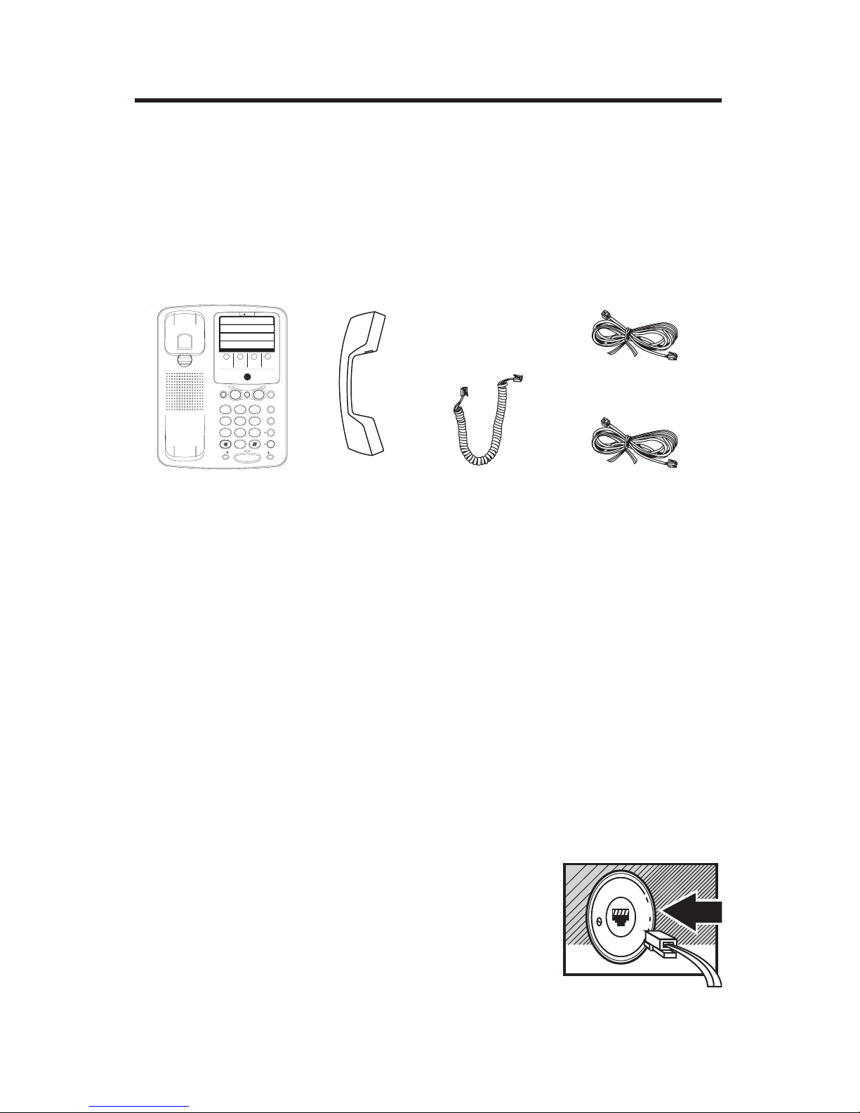
PARTS CHECKLIST
Your package should contain the following items:
Base unit
SHORT GLOSSARY OF TERMINOLOGY USED IN THIS MANUAL
Hook switch.The part of the phone that pops up to activate the phone
line when the handset is lifted from the base. On this phone, each of the
line buttons acts as a hook switch.
Line indicator.The light located next to each of the line buttons; it shows
you the status of each line (see page 8 for details).
Off-hook.A term used to describe the phone in its active mode. For this
phone, off hook would require that one of the line buttons is active.
On-hook. A term used to describe the phone in an inactive mode.
MODULAR JACK REQUIREMENTS
A modular jack USOC: RJ11C or a RJ14C is
required.
Installation of this telephone in locations
with 4-prong jacks or with hard-wired
outlets requires additional converters (not
included). The dealer from whom you
purchased the system, or a telephone
supply store, can advise you regarding the
proper converter.
Handset Handset cord 2-wire line cord
LINE 2LINE 2 PHONE NUMBERPHONE NUMBERPHONE NUMBERPHONE NUMBER LINE 1LINE 1
ABC
QUICK DIAL EMERGENCY NUMBERS
STORE
123
456
789
VOLVOL VOLVOL
LINELINE LINELINE
FLASHFLASH
PPAUSEAUSE
REDIALREDIAL
MUTEMUTE
HOLDHOLD
CONFERENCECONFERENCE
MEMOR MEMORY Y DIALDIAL
OPENOPEN
11
22
SPEAKERSPEAKER
11
22
ABCABC
44
GHIGHI
55
JKLJKL
66
MNOMNO
77
PQRSPQRS
88
TUVTUV
99
WXYZWXYZ
00
OPEROPER
33
DEFDEF
4-wire line cord
Page 6

6
INSTALLATION OPTIONS
Although you can use your GE 2-line business phone with a single phone
line, it is designed with a 2-line system in mind. The following diagrams
show two possible systems:
2 Lines on Separate Modular Jacks
It is possible that each line has its own RJ11
modular jack, which means that you will
need a 2-line coupler in order to use both
lines on this phone. Check with your local
phone dealer to get a two-line coupler.
2 Lines on a Single Modular Jack
The most common two-line phone system
uses a single RJ14 modular jack which
contains both phone lines.
Battery Installation
1. Remove the base plate by pressing down
the tabs and lifting it from the base.
BATTERY INSTALLATION
Install 4 AA batteries for Line-in-Use indicator, Ring indicator and Conference mode:
2. Press down with a flat tool or coin on the
tabs for the battery compartment lid and
lift up.
3. Insert the batteries as shown in the
diagram inside the battery compartment.
4. Snap the battery compartment lid back
into place and replace the base plate.
THIS END UP FOR WALL USE
THIS END UP FOR DESK USE
ATTENTION:
CAUTION:
+
+
+
+
_
_
_
_
THIS END UP FOR WALL USE
THIS END UP FOR DESK USE
Page 7

7
1
2
ABC3DEF
4
GHI5JKL6MNO
7
PRS8TUV9WXY
TONE
0
OPER
#
- VOL +
MUTE
TELEPHONE INSTALLATION
Your two-line phone can be placed on a level surface such as a tabletop or
desk, or you can mount it on the wall.
Plug the telephone line
cord into a modular jack
(RJ11 or RJ14) and into
the PHONE LINE jack
on the back of the unit.
Plug the handset
cord into the
handset, and into
the telephone jack
on the left side of
the unit.
TONE/PULSE
Set the PULSE/TONE switch to TONE if
you have Touch-Tone service, or to
PULSE if you have Pulse (rotary) service.
Ringer Volume
switches
TONE/PULSE
switch
DESK OR TABLETOP INSTALLATION
THIS END UP FOR WALL USE
THIS END UP
FOR DESK USE
PULSE
TONE
TONE/PULSE switch
Page 8

8
1. Rotate the handset hook.
WALL MOUNT INSTALLATION
1
2
3
4
5
6
7
8
9
10
11
12
13
14
15
16
LOWER
LINE 2LINE 2 PHONE NUMBERPHONE NUMBERPHONE NUMBERPHONE NUMBER LINE 1LINE 1
ABC
QUICK DIAL EMERGENCY NUMBERS
STORE
123
456
789
VOLVOL VOLVOL
LINELINE LINELINE
FLASHFLASH
PPAUSEAUSE
REDIALREDIAL
MUTEMUTE
HOLDHOLD
CONFERENCECONFERENCE
MEMOR MEMORY Y DIALDIAL
OPENOPEN
11
22
SPEAKERSPEAKER
11
22
ABCABC
44
GHIGHI
55
JKLJKL
66
MNOMNO
77
PQRSPQRS
88
TUVTUV
99
WXYZWXYZ
00
OPEROPER
33
DEFDEF
2. Set the TONE/PULSE switch to TONE if
you have touch-tone service or to PULSE
if you have pulse (rotary) service.
4. Plug the phone line cord into the phone
jack on the back of the unit.
THIS END UP FOR WALL USE
THIS END UP FOR DESK USE
PULS
E
TONE
3. Remove the base plate from the back by
pressing down on the snap tabs located
at the top and then lifting it off.
5. Reverse the direction of the Base Plate
and replace it by putting the tabs into the
slots on the top of the unit first, and then
snapping the bottom tabs into place.
6. Connect the phone cord to the modular
jack on the wall.
7. Slip the mounting holes over the wall
plate posts and slide the unit down firmly
into place. (Wall plate not included.)
8. Plug the handset cord into the handset
and into the unit, and then hang up the
handset.
Page 9

9
USING THE HANDSET
The only difference between using the handset with this phone and other
corded phones is that you must press a line number button after picking
up the handset in order to access that line.
TELEPHONE OPERATION
You can use the telephone by speaking and listening through the handset,
or by using the Speakerphone feature.
LINE STATUS INDICATOR LIGHTS
This two-line phone is designed for use at multiple stations, the status of
the indicator lights tells you what is happening on each line.
When the Indicator Light Is It Means
Off Line not in use
Red Line in use
Flashing Red Incoming call
Blinking Call on hold
SPEAKERPHONE LOCATION & USE GUIDELINES
For best speakerphone performance, avoid the following:
• Areas with high background noise. (The microphone might pick up
these sounds and prevent the speakerphone from going into the
receiving mode when you finish talking.)
• Surfaces affected by vibration.
• Recessed areas such as in a corner, under a cupboard,
or next to a cabinet, which can generate an echo effect.
Note the following guidelines when you use the speakerphone:
• The speakerphone works similar to a two-way radio in that you can only
listen or talk at one time.
• Stay reasonably close to the phone so that you can be clearly heard by
the person to whom you are talking.
• The speakerphone indicator light is on when the speakerphone is in use.
ANSWERING AND PLACING CALLS
Because this phone has two lines, you must choose a line by pressing the
corresponding line button in order to place an outgoing call or to answer
an incoming call.
NOTE: Batteries must be installed for the indicator lights to work.
Page 10

10
USING THE SPEAKERPHONE
To use the speakerphone feature, press a line button and then press
SPEAKER.
Placing a Call
1. Press the line number (1 or 2).
2. Press SPEAKER.
3. Dial the phone number you want to call.
4. Press SPEAKER to hang up.
Receiving a Call
1. Press the line number button next to the indicator that is flashing red to
answer an incoming call.
2. Press SPEAKER to answer the call.
3. Press SPEAKER to hang up the phone.
Placing a Call While Talking on Another Line
To place a call without hanging up on the first caller:
1. Press the HOLD button to put the first caller on hold.
2. Press the available line number button to get a dial tone.
3. Dial the phone number you want to call.
Receiving a Call While Talking on Another Line
When you receive a call while you are talking on another line, you hear the
phone ring.
1. Press the HOLD button to put the first caller on hold.
2. Press the line number button next to flashing red indicator light to
answer that call.
If you want to hang up on the first caller, just push the line button that is
flashing red to answer that line.
NOTE: You always need to put the first caller on hold before answering a
second call, or you will hang up on the first caller.
ADJUSTING HANDSET AND SPEAKER VOLUMES
The volume controls for the handset and speaker are separate, so you can
adjust one without affecting the other. Use the VOLUME arrows at the
bottom of the keypad to adjust the handset volume while using the
handset, or the speaker volume while using the speakerphone.
TIP: To return to the default volume settings, press both volume arrows at the
same time.
Page 11

11
USING THE FEATURES
This section discusses all of the basic telephone features.
REDIAL
Redial the last number you called by pressing the REDIAL button after you
get a dial tone.
NOTE: The Redial feature holds in memory the last numbers that you
pressed. If you pressed any numbers after dialing the phone number you last
called (for example, when accessing a voice-menu system) those numbers are
dialed.
If you get a busy signal, you can press REDIAL again without hanging up
to save some time in redialing the number.
HOLD
Use the HOLD button to interrupt a phone conversation without hanging
up; then resume the conversation on the same phone or an extension.
1. Press HOLD to place a line on hold (the line indicator flashes to show
you it’s on hold).
2. Press the line button to resume the conversation.
CONFERENCE CALLS
You can use the Conference Call feature when you have callers on both
lines, and want to have a three-way conversation.
To initiate a conference call:
1. Call the first party.
2. Place first party on hold.
3. Call the second party on the other line.
4. Press CONF.
To end a conference call:
• To disconnect both parties —Hang up
• To disconnect one party—Press the line button of the party to whom
you want to continue speaking.
• To put both parties on hold—Press HOLD.
• To speak to one party individually—Press HOLD; then press the line
number of the party to whom you want to speak (the second party
remains on hold).
NOTE: Batteries must be installed in Line 1 for Conference mode to work.
Page 12

12
MUTE
The MUTE button deactivates the microphone for both the speakerphone
and the handset, so that anything you say cannot be heard by the caller on
the other end of the line.
• Press MUTE to mute the microphone — the indicator light turns on.
• Press MUTE again to continue the phone conversation — the indicator
light turns off.
FLASH
Press the FLASH button instead of pressing the hook switch to activate
customer calling services such as call waiting or call transfer, which are
provided by your local phone company.
TEMPORARY TONE
If you have Pulse (rotary) service, and want to access customer calling
services that require Tone dialing (such as getting information from a local
bank), you can use this feature.
1. Press the TONE button ( * ) after you have connected to the customer
calling service to enable Tone dialing.
2. When you hang up, the phone automatically resumes Pulse dialing.
TIP: Temporary Tone can also be used while storing numbers in memory by
pressing TONE at the necessary point in storage sequence.
Page 13

13
MEMORY DIALING
You can store up to 12 numbers with the phone off-hook.
Be careful when you store numbers with the phone off-hook, because if
you do not follow the correct procedures, you might actually call someone
instead of storing their number in memory.
STORING A NUMBER
1. Pick up handset or press SPEAKER.
2. Press the STORE button.
3. Dial the number to be stored.
4. Press the STORE button again.
5. Press a number button to store the number and replace the handset or
press SPEAKER.
6. Record whose phone number it is on the memory directory (located
under the plastic cover on the front of the unit).
Use memory locations A, B and C to store emergency numbers, such as
the fire department, police and poison control
TIP: If you make a mistake while entering a number into memory, replace the
handset or press SPEAKER to start over again.
INSERTING A PAUSE IN THE DIALING SEQUENCE
Press the PAUSE button to insert a delay in the dialing sequence of a
stored telephone number when a pause is needed to wait for a dial tone
(for example after you dial 9 for an outside line, or to wait for a computer
access tone). Each pause counts as 2 digit in the dialing sequence.
STORING THE LAST NUMBER DIALED
Store the last number you dialed by pressing REDIAL instead of entering a
number in step 2 of the procedure for memory.
CHANGING A STORED NUMBER
To change a stored number, you replace it with a different number using
the procedure for storing a number. Just make sure that you update your
memory directory when you make changes.
Page 14

14
CLEARING A STORED NUMBER
To clear a stored number, just skip step 2 of the storing procedure (in other
words, do not enter a phone number).
DIALING A STORED NUMBER
Dial numbers from memory when using the handset or speakerphone.
When you get a dial tone, press the Memory Dial and then the number of
the memory location that has the number you want to call.
CAUTION: If you make test calls to emergency numbers, remain on the line
and explain the reason for the call to the dispatcher. Also, make these calls in
off-peak hours, such as early morning or late evening.
SPECIAL FEATURES
ADJUSTING THE LENGTH OF A FLASH
You can manually change the 0.6 second delay built into the default setting
of flash to adjust to a phone system requiring a different time. Check with
your phone company for the correct time needed.
1. Press STORE.
2. Press a number key between 1 and 9 to set a flash signal length between 0.1 and 0.9 seconds.
3. Press STORE again.
4. Press FLASH.
ADJUSTING THE LENGTH OF THE PAUSE FUNCTION
This telephone allows you to change the Pause function to suit a special
telephone situation. Normal Pause operation is a wait of 4 seconds before
continuing a dial sequence.
1. Press STORE.
2. Press a number key between 1 and 9 to select a pause duration between
1 second and 9 seconds.
3. Press STORE again.
4. Press PAUSE.
Page 15

15
TROUBLESHOOTING GUIDE
Problem Solution
No dial tone when • You must press a line button to get a dial tone.
you pick up handset
No dial tone when
you press a line button • Check hook switch. Does it pop up when handset
is picked up?
• Make sure phone line cord is connected.
Can't hear other party • Check handset or speaker volume.
Can’t be heard by • Make sure handset cord is securely plugged in.
other party
• Make sure phone cord is securely plugged in.
• Make sure MUTE indicator is off.
Will not dial. • Make sure TONE/PULSE is set to correct position.
Phone doesn’t ring • Check RINGER VOLUME.
• Make sure ringer is turned on.
• Could have too many phones on one line. (See
FCC registration information regarding REN)
Low handset or • Check the volume settings .
speaker volume
Line indicator lights but • Is ringer off?
phone doesn’t ring.
Telephone continues to • You must press the line number to answer a call.
ring after handset is
picked up.
Memory dialing • Make sure you entered numbers correctly.
Page 16

CARE AND MAINTENANCE
To keep your GE telephone working and looking good, follow these few
simple guidelines:
• Avoid putting telephone near heating appliances and devices that
generate electrical noise. (i.e., motors, fluorescent lamps.)
• Telephone should not be exposed to direct sunlight or moisture.
•
Avoid dropping the handset and other rough treatment to the phone.
• Clean telephone with a soft cloth. (Remember to first unplug the
phone from the wall outlet.)
• Never use a strong cleaning agent or abrasive powder, as this can
damage the finish.
• Retain the original packaging for future use.
SERVICE
FCC requires this product be serviced only by the manufacturer or its
authorized service agents. In accordance with FCC requirements, changes
or modifications not expressly approved by Thomson Consumer Electronics could void the user’s authority to operate this product. For instructions
on how to obtain service, refer to the warranty included in this guide.
Attach your sales receipt to the booklet for future reference or jot down the
date this product was purchased or received as a gift. This information will
be valuable if service should be required during the warranty period.
Purchase date _________________________________________________
Name of store _________________________________________________
Page 17

INDEX
Symbols
4-prong jacks 5
A
Adjusting the length of a flash 14
Adjusting the length of the pause
function 14
B
Base plate, removing 6
C
CONF 11
Conference call feature 11
ending 11
initiating 11
F
Flash 12, 14
H
HOLD 10, 11
I
Installation
desk or tabletop 7
wall mount 8
J
Jacks
4-prong 5
L
Line indicator 5
Line status indicator lights 9
M
Modular jack 5
MUTE 12
O
Off hook 5
On hook 5
P
Pause 13, 14
PULSE/TONE switch 8
R
REDIAL 11
used when storing numbers in
memory 13
RJ11 modular jack 6
RJ14 modular jack 6
S
SPEAKER 10
Special features 14
Stored numbers, changing 13
Stored numbers, clearing 13
Stored numbers, dialing 13
T
Temporary tone feature 12
TONE 12
V
VOLUME 10
resetting to default 10
Page 18

Model 2-9432
20876960 (Rev. 3 E/S)
98-10
Printed in Philippines
P.O. Box 1976, Indianapolis, IN 46206
© 1998 Thomson Consumer Electronics, Inc.
Trademark(s) ® Registered
Marca(s) Registrada(s)
LIMITED WARRANTY
What your warranty covers:
• Any defect in materials or workmanship.
For how long after your purchase:
• One year.
(The warranty for rental units begins with the first rental.)
What we will do:
• Provide you with a new, or at our option, a refurbished unit.
• The exchange unit is under warranty for the remainder of the original product’s warranty
period.
How to make a warranty claim:
• Properly pack your unit. Include any cables, etc., which were originally provided with the
product. We recommend using the original carton and packing materials.
• Include in the package evidence of purchase date such as the bill of sale. Also print your
name and address and a description of the defect. Send standard UPS or its equivalent to:
Thomson Consumer Electronics, Inc.
Product Exchange Center
32B Spur Drive
El Paso, Texas 79906
• Pay any charges billed to you by the Exchange Center for service not covered by the
warranty.
• A new or refurbished unit will be shipped to you prepaid freight.
What your warranty
does not
cover:
• Customer instruction. (Your Owner’s Manual provides information regarding operating
instructions and user controls. For additional information, ask your dealer.)
• Installation and set-up service adjustments.
• Batteries.
• Damage from misuse or neglect.
• Products which have been modified or incorporated into other products.
• Products purchased or serviced outside the USA.
• Acts of God, such as but not limited to lightning damage.
Product Registration:
• Please complete and mail the Product Registration Card packed with your unit. It will
make it easier to contact you should it ever be necessary. The return of the card is not
required for warranty coverage.
How state law relates to this warranty:
• This warranty gives you specific legal rights, and you may have other rights which vary
from state to state.
If you purchased your product outside the USA:
• This warranty does not apply. Contact your dealer for warranty information.
 Loading...