

Page 1
GE
Security
16-Channel Contact/TTL Data System
Models 250D and 2250D
installation instructions
11-0250-251099-A
Page 2
250D and 2250D
GENERAL
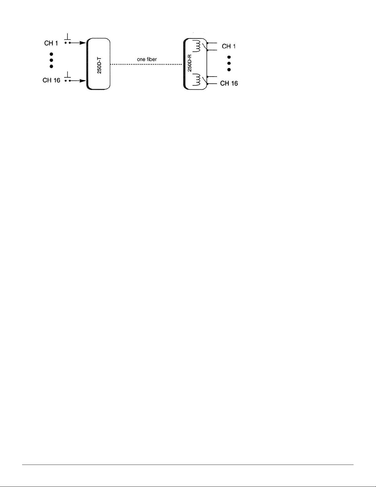
The GE Security 250D system transmits up to 16 channels of low-speed digital data, switch/status
information, or control/function signals. The user may program the receiver to provide 16 channels
of alternate-action outputs , or eight channels of each type. Outputs are TTL drivers or N/O
reed relays.
ABOUT THE SYSTEM
Units are designed for rack mounting in the GE Security Card Cage, 517R Racking System, or in the
501R Miniature Enclosure. If you have ordered standalone units, they have been shipped in a 501R
(figure 3, page 3).
Each unit occupies one card-cage slot. Units in the 515R or the 517R are powered from the rack.
If using the 501R Miniature Rack, the GE Security power supply, model number 613P is required
ed separately). Inputs to the transmitter, thr
der
(or
to +5 volts by means of a 1K ohm pull-up resistor. A closure to ground or an open collector to ground
will activate a particular channel. The r
channel. The r
may be activated at any time. The transmitter’s closure need only be momentary, alternate action, or
a combination of momentary and alternate action.
elays ar
e normally open and the TTL is normally low. Any number of channels up to 16
eceiver has a corresponding dry closure or TTL output for each
ough the 44-pin connector
, are normally held high
TTL OUTPUTS
The receivers are set for relay operation at the factory. If TTL outputs are desired, four switches are
provided to conv
OPTICAL INDICA
Transmitters include a status LED which, when green, indicates data is being sent.
Receivers include a LEVEL/LOSS indicator which is used to determine received optical power.
This LED will glow green when sufficient optical power is received. If this LED is off, it indicates that
optical power is not being received and would suggest that the fiber is open or, less likely,
the transmitter or receiver is inoperative.
MOMENT
Receiver outputs may be set in the field by the user for the desired operating conditions, either 16
channels of momentary operation, 16 channels of alternate action, or eight channels of each type.
o mak
T
receiver card. For 16 channels of momentary operation, remove both jumpers. For 16 channels of
alternate action operation, install both jumpers. For 8 channels of each type of operation, remove the
E0 jumper and install the E1 jumper. Units are shipped with both units installed (all-alternate-action).
In the ev
TTL outputs will be low.
IN CASE OF PROBLEMS
If problems should be encountered, first check to be sure power is properly connected to the modules.
Also verify that the fiber is good. Then, check the transmitter status indicators. If lit, data is present.
Check the Lev
is functional.
AR
e adjustments, locate jumper
ent of pow
ert the channels to TTL in groups of four. Refer to figure 1 for the location of the switches.
TORS
Y OR AL
TERNATE ACTION OPERATION
s E0 and E1 (figur
er failur
el/Loss indicator
e, when pow
s on the r
e 1 abov
er is restored, all relays will be in the OPEN position, and the
eceivers. If they are green, the fiber optic cable connection
e) found near the 8031 pr
ocessor on the
If any pr
following information available: exact model number, product code, and serial numbers of your fiber
optic links, and a listing of the diagnostic indicators and their respective color/condition.
oblems arise, please contact the GE Security customer ser
vice depar
tment and hav
e the
Page 3

250D and 2250D
NOTE: To provide earth ground reference, Stand Alone (Enclosure) modules need
to be connected to a good earth gr
a copper
to an approved earth ground.
-based conductor fr
ound. This can be accomplished by connecting
om the modules
DC Common/Ground pin
Page 4

250D and 2250D
Customer Support
For assistance in installing, operating, maintaining, and troubleshooting this product,
refer to this document and any other documentation provided. If you still have questions,
please contact technical suppor
t during normal business hour
excluding holidays, between 6 a.m. and 5 p.m. Pacific Time).
GE Security
Call: 888 437-3287 (US, including Alaska and Hawaii; Puerto Rico; Canada)
Outside the toll-free area: 503 885-5700
Fax: 561 998-6224
gesecurity.com
.
www
U.S.
GESecurity.
.
www
As a company of innov
For the latest pr
11-0250-251099-A Released MAY-07
com
ation, GE Security r
oduct specifications visit GE Security online at www
T (561) 998-6100
T 888-GE-SECURIT
888 (437-3287)
F 561 998-6224
E gesecuritycustserv@ge.com
eserves the right to change product specifications without notice.
com or contact your GE Sales R
GESecurity.
.
Y
s (Monday thr
epresentative.
ough Friday,
Asia
T 852-2907-8108
F 852-2142-5063
Australia
T 613-9239-1200
F 613-9239-1299
Canada
T 519-376-2430
F 519-376-7258
Europe
T 44-113-238-1668
F 44-113-253-8121
Copyright © 2007 General Electric Company. All rights reserved.
Latin America
T 305-593-4301
F 305-593-4300
 Loading...