

Page 1
User Manual
3 Speed Wall Control for Fans
MODEL: 22158
120V 60Hz, MADE IN CHINA
Customer Assistance
1-866-885-4649
customerservice@skyplug.com
Contact a qualified electrician or call the Customer Care Service Team at 1-866-885-4649
Customer Service hours of operation are 9:00AM-5:00PM EST -Monday-Friday
customerservice@skyplug.com
Register your GE Branded product for warranty coverage on
www.gelightingandfans.com
Page 2

Safety Rules
READ AND SAVE THESE INSTRUCTIONS
1. To reduce the risk of electric shock, ensure electricity has been turned off at the circuit breaker or fuse box
before beginning.
2. All electrical connections must be made in accordance with local codes, ordinances and/or the National
Electric Code. Electrical installation should be performed by a qualified licensed electrician.
3. CAUTION: To reduce the risk of fire or injury, do not use this product in conjunction with any variable
(rheostat) wall control.
4. CAUTION: Do not use control with a fan and light that operate with the same switch.
5. WARNING: Do not connect wires across live/hot and neutral. This switch must only break the live/hot
line. Connecting the wires across live/hot and neutral will damage the control permanently.
6. Use only one control in a 3-way circuit.
7. Use control with a ceiling paddle fan only. Use only one ceiling paddle fan per control.
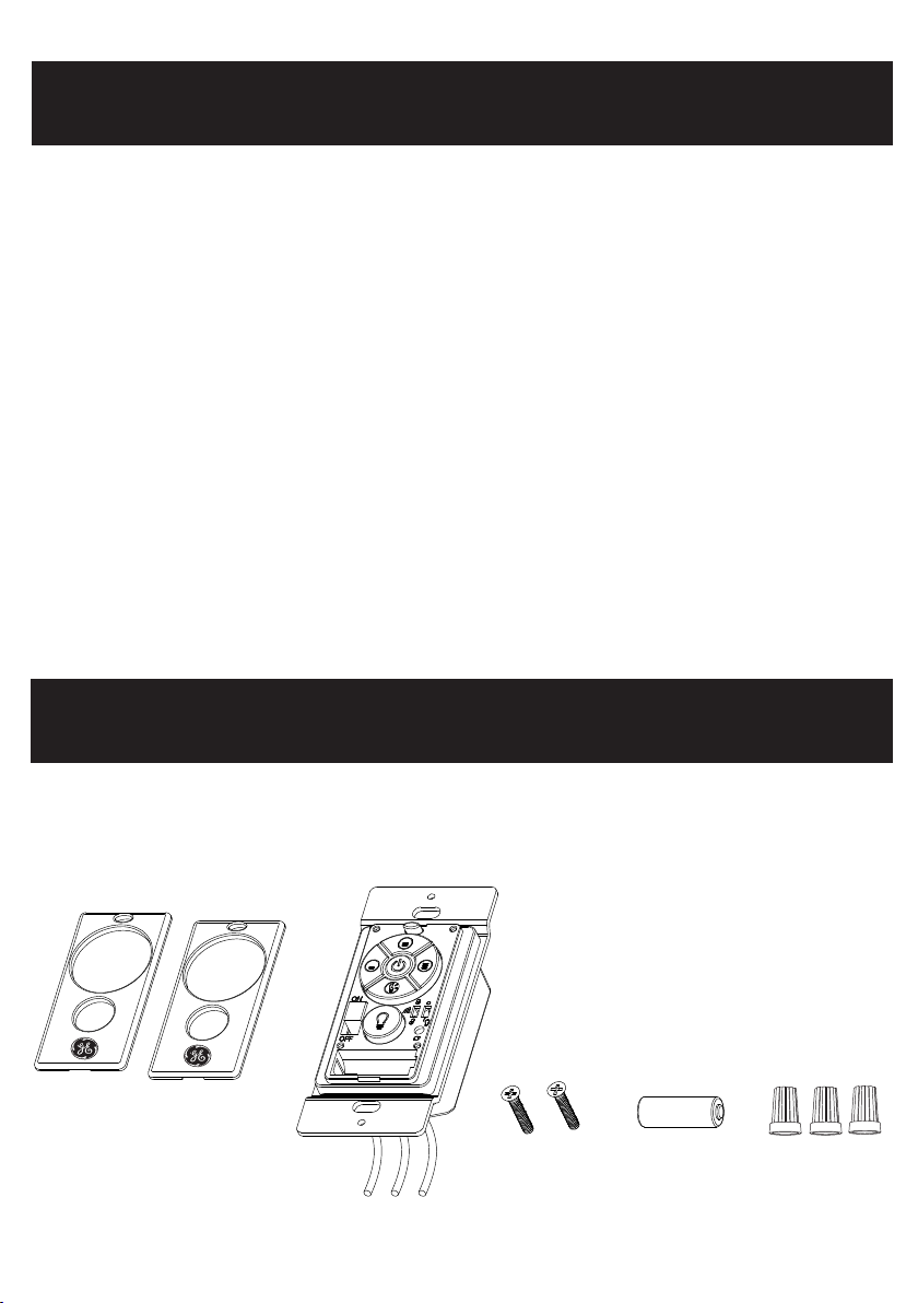
Parts List
panel in white
1
panel in ivory
wall control
#6- 32x 3/4"
screws
23A 12V
battery
wire nuts
Page 3

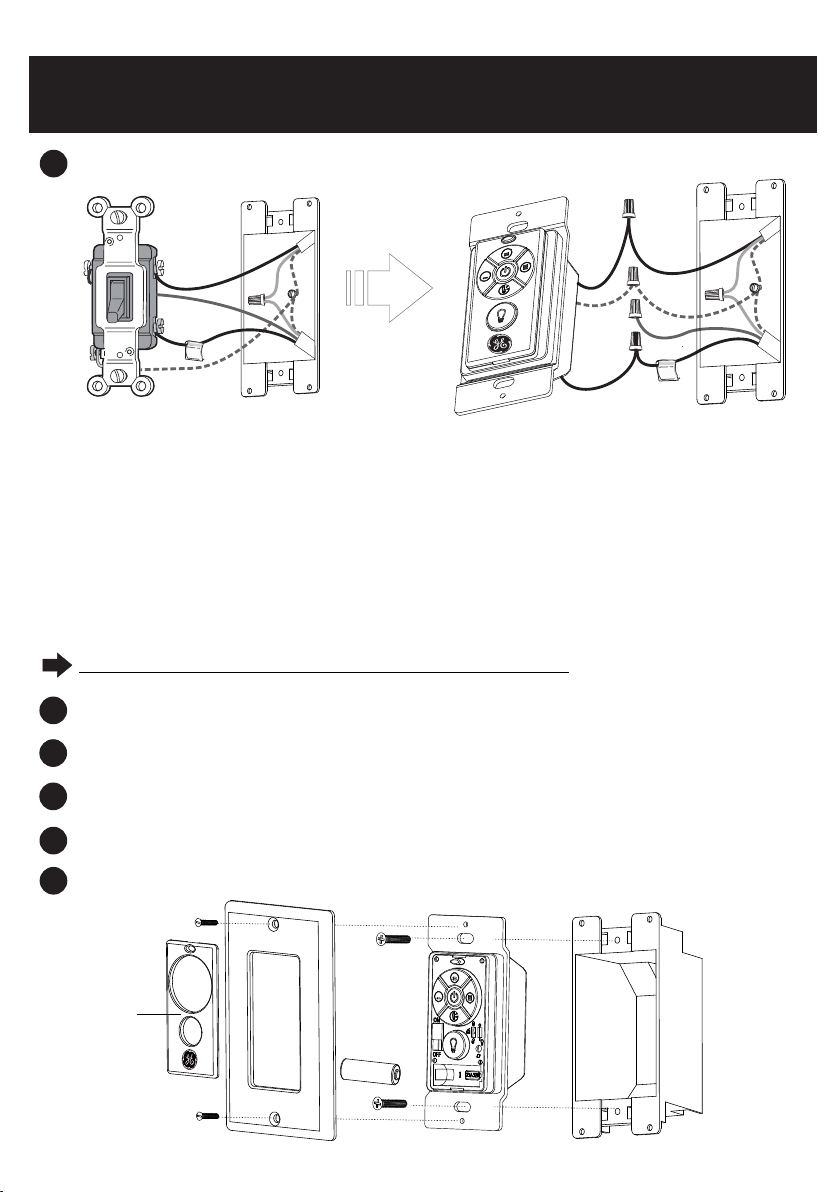
Wall Control Installation
1
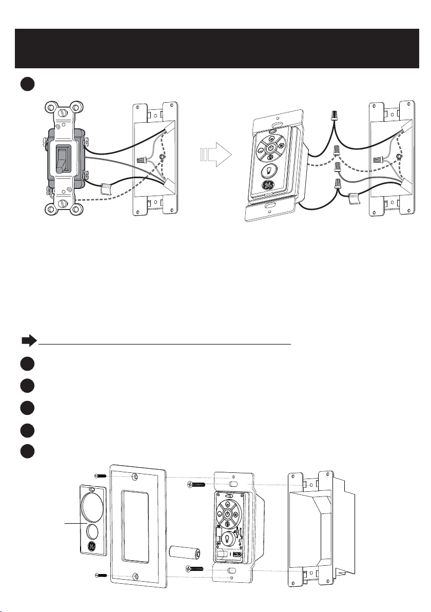
Shut OFF power to the switch at circuit breaker or fuse box . Verify power is OFF on the switch box
before continuing.
2
Remove the existing wallplate and switch from switch box.
IMPORTANT NOTE: Your wall switch may have two wires attached to the same screw as shown
below. Tape these two wires together before disconnecting.
TAPE
or
TAP
E
A
Determine the type of circuit to make the wiring. Normally the switch is wired with a single pole switch or 3-
3
way switch. Please follow below wiring instructions.
CAUTION: Please if you are not contact a qualified electrician, or call customer service 1-866-885-4649
certain of wiring.
WARNING: Do not connect wires across LIVE/HOT and NEUTRAL. This control must only break the
LIVE/HOT line.
B
SINGLE-POLE APPLICATION
3A
BLACK
BLACK
BLACK
GRE EN/BA RE
BLACK
-Connect one black wire from the wall control to one of the black wires removed from the switch.
-Connect the second black wire from the wall control to the other black wire removed from the switch.
If you had taped together two black wires from the switch, connect both wires to the control.
-If your switch box has a ground wire (green or bare copper), connect the green wire from the wall
control to the ground wire removed from the switch. If not , connect the green wire from the wall
control directly to one of the screws on the switch box.
Secure wire nuts to ensure that no bare wire is exposed.
GRE EN
BLACK
GRE EN
/BARE
BLACK
2
Page 4
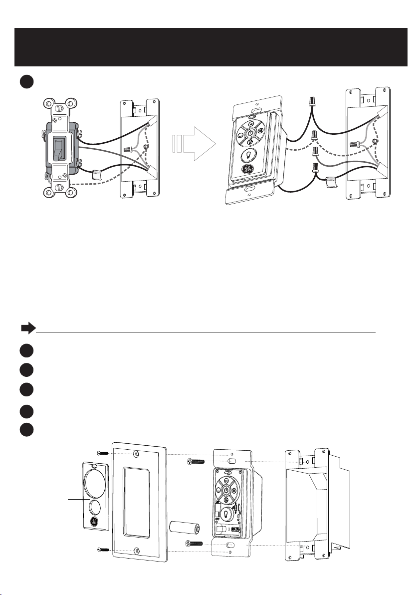
Wall Control Installation
3-WAY APPLICATION
3B
BLACK
BLACK
BLACK
TAG
GRE EN
/BA RE
RED
GRE EN
- Connect one black wire from the wall control to the tagged wires removed from the switch.
- Connect second black wire from the wall control to the other black wire removed from the switch.
If you had taped together two black wires from the switch, connect both wires to the control.
- Cap off the red wire removed from the switch.
-If your switch box has a ground wire (green or bare copper), connect the green wire from the wall
control to the ground wire removed from the switch. If not , connect the green wire from the wall
control directly to one of the screws from the switch box.
Secure wire nuts to ensure that no bare wire is exposed.
REFER TO DIAGRAM SHOWN BELOW TO COMPLETE INSTALLATION
BLACK
GRE EN
/BA RE
RED
TAG
Secure wall control to the switch box using the screws provided.
4
5
Install the 23A 12V battery provided into the compartment .
Secure a decor style wall plate to the wall control using the screws that come with the wall plate.
6
Slide the ON/OFF switch on the wall control to “ON” position.
7
Attach the panel to the wall control, aligning the holes.
8
Pan el
3
Page 5
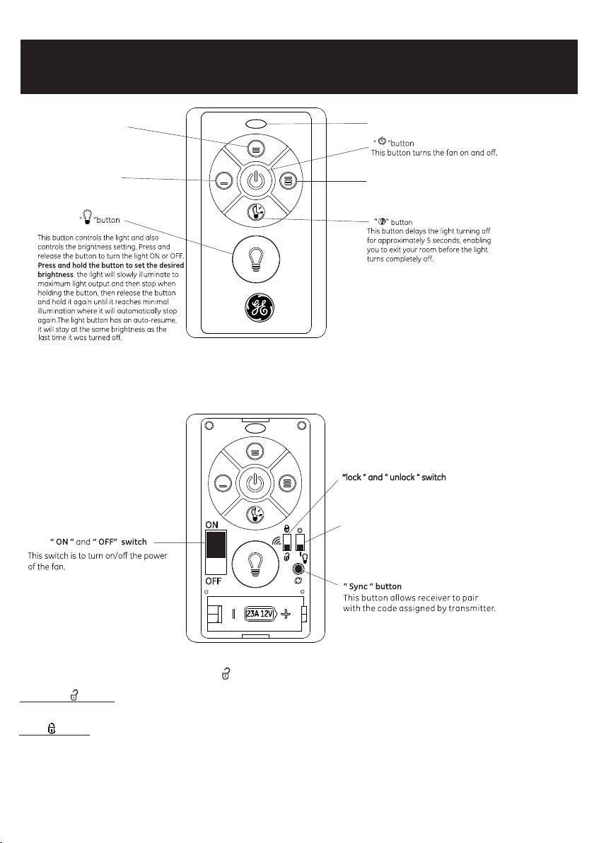
Wall Control Operation
Medium Speed
Low Speed
Operation Indicator
High Speed
NOTE:
For convenience, the transmitter has been
preset by the factory in the unlock position.
With this setting the transmitter will work
with GE Branded compatible fans without any
further programing.
“ O ” and “ I ” dim switch
For t his fan , the dim s witch s hould b e in
the “ I” posi tion, a llowi ng for di mming o f
the l ight . Place the s witch i n the “0"
pos ition t o turn th e dimmi ng feat ure off
if yo u do not want th e dimmi ng feat ure.
-
Lock/unlock switch when placed in the unlock position allows a common code to be sent .
In the unlock position :
configuration.
In lo ck posi tion : Al lows a un ique co de to be se nt to the r eceiver in t he fan. O nly the rece iver of t his fan w ill be sy nced wi th this t ransm itter i n
loc k posit ion. Mo re than o ne fan ca n be sync ed with o ne tran smitt er, in this c ase-f ollow s ync ins truct ion for e ach fan .
NOTE:
-To prevent d amage t o trans mitte r, rem ove the batt ery if no t used fo r long pe riods .
-Pl ease co ntact y our loc al batt eries recycli ng cent er for pr oper ba ttery d ispos al info rmati on.
The transmitter will send a common code, this transmitter will operate all other GE BRANDED fans with the same receiver
4
Page 6
Wall Control Syncing
Step 2. Install the 23A 12V battery provided.
Hold button to cycle between maximum and
minimum light.
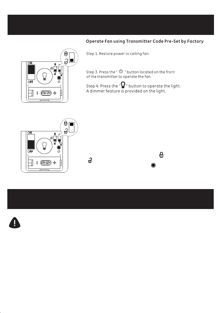
In Case Of Interference With Several Fans, You Can Change
The Transmitter Code To Operate A Single Fan Only.
Step 1. Switch off the power to the fan.
Step .2 Use the on/off switch on the transmitter to
turn power on to the fan.
Step 3. Within 30 sec, switch the lock “ ” / unlock
“ ” switch on the front of the transmitter to lock
position. And then push the sync “ ” button for
approximately 5-10 sec, until the fan light kit
flashes 3 times.
Trouble Shooting
CAUTION: Shut off main power supply before carrying out any of these checks.
1. Fan will not start:
-Check main and branch circuit fuses or breakers.
-Check to make sure the wall switch is in the on position.
Remote control will not work:
2.
- Ensure the control is wired correctly and receiving power.
- Ensure battery is new and installed correctly.
- Ensure the switches are set correctly.
- Sync the remote by following the syncing procedure above.
5
Page 7

Specification
Factory Model:FAN-67T-3SP
Rating: 120V~ 60Hz Max.2A
FCC ID: 2AAZPFAN67T3SP / I C : 11037A-FAN67T3SP
This device complies with part 15 of the FCC Rules and RSS-210 Issue 8. Operation is subject to the following
two conditions:
1. This device may not cause harmful interference
2. This device must accept any interference received, including interference that may cause undesired
operation.
CAUTION: Any changes or modifications not expressly approved by the party responsible for compliance
could void the user's authority to operate the equipment .
NOTE: This equipment has been tested and found to comply with the limits for a Class B digital device
pursuant to part 15 of the FCC Rules and the limits pursuant to RSS-210 Issue 8.
These limits are designed to provide reasonable protection against harmful interference in a residential
installation. This equipment generates, uses and can radiate radio frequency energy and, if not installed and
used in accordance with the instructions, may cause harmful interference to radio communications.
However, there is no guarantee that interference will not occur in a particular installation. If this equipment
does cause harmful interference to radio or television reception, which can be determined by turning the
equipment off and on, the user is encouraged to try to correct the interference by one or more of the
following measures:
-Reorient or relocate the receiving antenna.
-Increase the separation between the equipment and the receiver.
-Connect the equipment into an outlet on a circuit different from that to which the receiver is connected.
6
Page 8

Manuel de l’utilisateur
Commande murale 3 vitesses pour ventilateurs
MODÈLE: 22158
120V 60Hz, FABRIQUÉ EN CHINE
Assistance à la clientèle
1-866-885-4649
customerservice@skyplug.com
Contacter un maître technicien ou appeler l’équipe du service après-vente au 1-866-885-4649
Les heures d’ouverture du service après-vente sont de 9 h à 17 h (Heure de l’Est) du lundi au vendredi
Enregistrez votre produit de la MARQUE GE pour la couverture de garantie sur
customerservice@skyplug.com
www.gelightingandfans.com
Page 9
Consignes de sécurité
LIRE ET CONSERVER CES INSTRUCTIONS
1. Afin de réduire le risque de décharge électrique, s’assurer que l’alimentation électrique est coupée à partir du
disjoncteur ou de la boîte à fusibles avant de commencer.
2. Toutes les connexions électriques doivent être conformes aux codes locaux, décrets et/ou au Code électrique
national. L’installation électrique doit être effectuée par un maître électricien.
3. ATTENTION : Afin de réduire le risque d’incendie de blessure, ne pas utiliser ce ventilateur avec une
commande murale régulatrice (rhéostat).
4. ATTENTION : Ne pas utiliser la commande avec un ventilateur et une lumière qui fonctionnent avec le
même commutateur.
5. AVERTISSEMENT : Ne pas connecter les fils sur une ligne sous tension/à chaud et neutre. Ce commutateur
ne peut couper que la ligne sous tension/à chaud. La connexion des fils sur une ligne sous tension/à chaud et
neutre endommagera la commande de façon permanente.
6. Utiliser uniquement une commande sur un circuit 3 voies.
7.
Utiliser la commande uniquement un ventilateur de plafond à pales. Utiliser uniquement un ventilateur de
plafond à pales par commande.
Liste des pièces
panneau blanc
1
panneau ivoire
Commande murale
vis #6-32x3/4"
pile 23A 12V
marrettes
Page 10

Installation de la commande murale
1
Couper l’alimentation (OFF) du commutateur au niveau du disjoncteur ou de la boîte à fusibles. Vérifier
que l’alimentation est coupée (OFF) au niveau du boîtier de l’interrupteur avant de poursuivre.
2
Retirer la plaque murale existante et commuter depuis le boîtier de l’interrupteur.
REMARQUE IMPORTANTE : Le commutateur mural peut avoir deux fils fixés à la même vis comme
indiqué ci-dessous. Attacher ces deux fils ensemble avec de l’adhésif avant la déconnexion.
RUBAN
ADHÉSIF
RUBAN
ADHÉSIF
ou
A
Identifier le type de circuit pour effectuer le câblage. Normalement, le commutateur est connecté par un fil
3
avec un commutateur unipolaire ou un commutateur 3 voies. Suivre les instructions ci-dessous pour
procéder au câblage
ATTENTION : Contacter un maître électricien ou appeler le service clientèle au 1-866-885-4649 concernant
les questions sur le câblage.
AVERTISSEMENT : Ne pas connecter les fils sur une ligne SOUS TENSION/À CHAUD et NEUTRE. Cette
commande ne peut couper que la ligne SOUS TENSION/À CHAUD.
3A APPLICATION UNIPOLAIRE
3A
NOIR
VERT/NU
NOIR
- Connecter un fil noir de la commande murale à l’un des fils noirs retirés du commutateur.
- Connecter le deuxième fil noir de la commande murale à l’autre fil noir retiré du commutateur.
Si vous avez attaché les deux fils noirs du commutateur ensemble avec de l’adhésif, connecter les deux
fils à la commande.
- Si votre boîtier de l’interrupteur possède un fil de terre (vert ou cuivre nu), connecter le fil vert de la
commande murale au fil de terre retiré du commutateur. Sinon, connecter le fil vert de la commande murale
directement à l’une des vis du boîtier de l’interrupteur.
Fixer les marrettes pour garantir qu’aucun fil nu n’est exposé.
NOIR
VERT
NOIR
NOIR
VERT
/NU
NOIR
B
2
Page 11
APPLICATION 3 VOIES
3B
Installation de la commande murale
NOIR
VERT
/NU
ROUGE
RUB
VERT
/NU
RUB
NOIR
ROUGE
NOIR
VERT
NOIR
- Connecter un fil noir de la commande murale sur les fils étiquetés retirés du commutateur.
- Connecter le deuxième fil noir de la commande murale à l’autre fil noir retiré du commutateur.
Si vous avez attaché les deux fils noirs du commutateur ensemble avec de l’adhésif, connecter les deux
fils à la commande.
- Enlever le capuchon du fil rouge retiré du commutateur.
- Si votre boîtier de l’interrupteur possède un fil de terre (vert ou cuivre nu), connecter le fil vert de la
commande murale au fil de terre retiré du commutateur. Sinon, connecter le fil vert de la commande murale
directement à l’une des vis sur le boîtier de l’interrupteur.
Fixer les marrettes pour garantir qu’aucun fil nu n’est exposé.
CONSULTER LE SCHÉMA CI-DESSOUS POUR TERMINER L’INSTALLATION
Fixer la commande murale au boîtier de l’interrupteur à l’aide des vis fournies.
4
5
Installer la pile 23 A 12 V fournie dans le compartiment.
Fixer une plaque murale de décoration à la commande murale à l’aide des vis fournies avec la plaque murale.
6
Placer le commutateur ON/OFF de la commande murale en position « ON ».
7
Fixer le panneau à la commande murale, en alignant les orifices.
8
Panneau
3
Page 12

Fonctionnement de la commande murale
Vitesse modérée
Vitesse faible
Bouton « »
Ce bouton commande la lumière ainsi que
le réglage de la luminosité. Appuyer sur le
bouton puis le relâcher pour allumer (ON)
ou éteindre (OFF) la lumière. Appuyer et
maintenir le bouton enfoncé pour régler
la luminosité souhaitée : la lumière
s’allumera lentement jusqu’à la puissance
lumineuse maximale et puis arrêtera
lorsque le bouton est enfoncé. Ensuite,
relâcher le bouton et le maintenir à
nouveau enfoncé jusqu’à ce qu’il atteigne
un éclairage minimal, où il s’arrêtera à
nouveau automatiquement. Le bouton de
lumière dispose d’une fonction de reprise
automatique, qui permet de revenir à la
même luminosité que celle lors de sa
dernière extinction.
Commutateur « ON » et « OFF »
Ce commutateur sert à mettre le
ventilateur sous/hors tension.
Témoin de fonctionnement
Bouton « »
Ce bouton permet d’allumer et d’éteindre
le ventilateur.
Vitesse élevée
Bouton « »
Ce bouton permet de retarder l’extinction de la
lumière pendant environ 5 secondes, permettant
ainsi de sortir de la pièce avant que la lumière ne
s’éteigne complètement.
REMARQUE :
Pour plus de commodité, l’émetteur a été préréglé
en usine en position de déblocage. Avec ce
réglage, l’émetteur fonctionnera avec les
ventilateurs compatibles de la MARQUE GE sans
programmation supplémentaire.
Commutateur de « blocage » et « déblocage »
Régulateur de luminosité « O » et « I »
Pour ce ventilateur, le régulateur de luminosité
doit être en position « I » pour permettre une
diminution graduelle de la lumière. Mettre le
commutateur en position « 0 » pour
désactiver la fonction si une.
Bouton « Sync »
Ce bouton permet de jumeler le récepteur avec le code
attribué par l’émetteur.
- Le commutateur de blocage/déblocage en position de déblocage permet l’envoi d’un code commun.
En position de déblocage : l’émetteur enverra un code commun, cet émetteur actionnera tous les autres ventilateurs de la MARQUE GE
avec la même configuration de récepteur.
En position de blocage : l’émetteur permet l’envoi d’un code unique au récepteur du ventilateur. Seul le récepteur de ce ventilateur est synchronisé
avec cet émetteur en position de blocage. Plusieurs ventilateurs peuvent être synchronisés avec un seul émetteur, dans ce cas, suivre les instructions de
synchronisation pour chaque ventilateur.
REMARQUE :
- Pour éviter d’endommager l’émetteur, retirer la pile si elle ne va pas être utilisée pendant de longues périodes.
- Contacter votre centre local de recyclage de piles pour les informations pertinentes relatives à l’élimination des piles.
4
Page 13

Synchronisation de la commande murale
Fonctionnement du ventilateur à l’aide du code de l’émetteur
Étape 1. Rétablir l’alimentation pour le ventilateur de plafond.
Étape 2. Installer la pile 23 A 12 V fournie.
Étape 3. Appuyer sur le bouton « » situé sur l’avant de l’émetteur
pour actionner le ventilateur.
Étape 4. Appuyer sur le bouton « » pour allumer la lumière.
Il est possible d’utiliser une fonction de gradation de la luminosité
avec l’éclairage.
Maintenir le bouton pour faire défiler les réglages d’éclairage
En cas d’interférence avec plusieurs ventilateurs, il est possible
de modifier le code de l’émetteur pour pouvoir actionner un
seul ventilateur.
Étape 1. Couper l’alimentation du ventilateur.
Étape 2. Utiliser le commutateur on/off sur l’émetteur pour mettre
le ventilateur sous tension.
Étape 3. Dans un intervalle de 30 secondes, mettre le commutateur
de blocage « »/déblocage « » situé sur l’avant de l’émetteur
en position de blocage. Puis enfoncer le bouton de synchronisation
« » pendant environ 5 à 10 secondes, jusqu’à ce que la trousse
d’éclairage du ventilateur clignote 3 fois.
Dépannage
ATTENTION : Couper l’alimentation principale avant d’effectuer un de ces contrôles.
Le ventilateur ne démarre pas :
1.
- Vérifier les disjoncteurs et les fusibles de circuits principaux et de dérivation.
- Vérifier que l’interrupteur mural est en position de marche.
2. La télécommande ne fonctionne pas :
- S’assurer que la commande est branchée correctement et alimentée.
- S’assurer que la pile est neuve et installée correctement.
- S’assurer que les commutateurs sont correctement réglés.
- Synchroniser la télécommande en suivant la procédure de synchronisation ci-dessus.
5
Page 14

Specification
Modèle industriel : FAN-67T-3SP
Régime nominal : 120 V~ 60 Hz Max. 2 A
ID FCC : 2AAZPFAN67T / IC : 11037A-FAN67T...
Cet appareil est conforme à la partie 15 des règles de la FCC et à la norme CRN-210 8e édition. Le fonctionnement
est soumis aux deux conditions suivantes :
1. Cet appareil ne doit pas provoquer d’interférences nuisibles
2. Cet appareil doit accepter toute interférence reçue, y compris les interférences qui peuvent causer un mauvais
fonctionnement.
ATTENTION : Tout changement ou modification non expressément approuvés par la partie responsable de la
conformité pourrait annuler l’autorisation de l’utilisateur à utiliser l’équipement.
REMARQUE : Cet équipement a été testé et jugé conforme aux limites d’un appareil numérique de classe B,
conformément à la partie 15 des règles de la FCC et aux restrictions de la norme CRN-210 8e édition.
Ces limites sont conçues pour fournir une protection raisonnable contre les interférences nuisibles dans une
installation résidentielle. Cet équipement génère, utilise et peut émettre une énergie de radiofréquence et, si non
installé et utilisé conformément aux instructions, il peut causer des interférences nuisibles aux communications
radio. Cependant, il n’y a aucune garantie que l’interférence ne se produira pas dans une installation particulière. Si
cet appareil provoque des interférences nuisibles à la réception radio ou de télévision, ce qui peut être déterminé en
mettant l’appareil hors et sous tension, l’utilisateur est invité à essayer de corriger l’interférence par une ou plusieurs
des mesures suivantes :
-Reorient or relocate the receiving antenna.
-Increase the separation between the equipment and the receiver.
-Connect the equipment into an outlet on a circuit different from that to which the receiver is connected.
est une marque de commerce de la compagnie General Electric et est
utilisée sous licence par SQL Lighting and Fans LLC.
4400 North Point Parkway, Suite 265, Alpharetta, GA 30022
6
Page 15

Manual de Usuario
Control remoto de pared de 3 velocidades para
ventiladores
MODELO: 22158
120V 60Hz, HECHO EN CHINA
Servicio al Cliente
1-866-885-4649
customerservice@skyplug.com
Contacte a un electricista calificado o llame al Equipo del Servicio al Cliente al 1-866-885-4649 Horas
de operación del Servicio al Cliente son de 9:00AM-5:00PM Hora Estándar del Este-Lunes-Viernes
Registre su producto MARCA GE para la cobertura de su garantía en
customerservice@skyplug.com
www.gelightingandfans.com
Page 16

Para su seguridad
LEA Y GUARDE ESTAS INSTRUCCIONES
1. Para reducir el riesgo de corto eléctrico, asegúrese que la electricidad este apagada en el panel eléctrico o caja
de fusibles antes de comenzar.
2.
Todas las conexiones eléctricas deben hacerse de acuerdo a los códigos locales, reglamentos y/o Código
Eléctrico Nacional. Un electricista calificado y licenciado deberá realizar la instalación eléctrica.
3.
CUIDADO: Para reducir el riesgo de incendio o lesiones, no use este producto conjuntamente con ningún
control de pared variable (reóstato).
4. CUIDADO: No use este control con ningún ventilador y luz que funcionen con el mismo interruptor.
5.
ATENCION: No conecte cables atravesados entre el vivo/caliente y neutral. Este interruptor debe interferir
solo con la línea viva/caliente. Conectar los cables atravesados entre el vivo/caliente y neutral dañará el
control permanentemente.
Use solamente un control en un circuito de 3 vías.
6.
7 . Use el control con un ventilador de techo solamente. Use solamente un ventilador de techo con cada control.
Lista de Partes
Panel blanco
1
Panel marfil
Control de pared
Tornillos #6-32x3/4
pulgadas
Batería 23A
12V
Conectores
de cables
Page 17

Instalación del Control de Pared
1
Apague el interruptor en el panel eléctrico o caja de fusibles. Verifique que la energía esta apagada en la
caja de fusibles antes de continuar.
2
Retire el cobertor de la pared e interruptor de la caja del interruptor.
NOTA IMPORTANTE: Su interruptor de pared puede que tenga dos cables adjuntos al mismo tornillo
como se muestra abajo. Junte estos dos cables con cinta adhesiva antes de desconectarlos.
CINTA
ADHESIVA
CINTA
ADHESIVA
o
A
Determine el tipo de circuito para hacer el cableado. Normalmente el interruptor esta alambrado con un
3
interruptor sencillo o un interruptor de vías. Favor de seguir las siguientes instrucciones para realizar el
cableado.
CUIDADO: Favor de contactar a un electrificado calificado o llamar al servicio and cliente al 1-866-885-4649
si usted no esta seguro de algún tipo de cableado.
ATENCION: No conecte cables atravesados entre el VIVO/CALIENTE y NEUTRAL. Este control solo
deberá activar la línea VIVA/CALIENTE.
APLICACIÓN SENCILLA
3A
NEGRO
VERDE/DESNUDO
NEGRO
- Conecte un cable negro del control de pared a uno de los cables negros que removió del interruptor.
- Conecte el segundo cable negro del control de pared al otro cable negro que removió del interruptor.
Si usted había adherido juntos los dos cables negros del interruptor, conecte ambos cables al control.
- Si su caja del interruptor tiene un cable a tierra (verde o desnudo de cobre), conecte el cable verde a tierra
del control de pared al cable a tierra que removió del interruptor. Sino conecte el cable verde a tierra
directamente a uno de los tornillos en la caja del interruptor.
Asegure los cables con los conectores de cable para asegurarse que no hay cables desnudos
expuestos.
NEGRO
VERDE
NEGRO
NEGRO
VERDE
/DESNUDO
NEGRO
B
2
Page 18
APLICACIÓN DE 3 VIAS
3B
Instalacion del Control de Pared
NEGRO
VERDE
/DESNUDO
ROJO
CIN
NEGRO
CIN
VERDE
/DESNUDO
ROJO
NEGRO
VERDE
NEGRO
- Conecte un cable negro del control de pared a uno de los cables de removió del interruptor.
- Conecte el segundo cable negro del control de pared al otro cable negro que removió del interruptor.
Si usted adjunto los dos cables negros del interruptor, conecte ambos cables al control.
- Tape el cable rojo del interruptor con uno de los conectores de cables.
- Si su caja del interruptor tiene un cable a tierra (verde o desnudo de cobre), conecte el cable verde del
control de pared al cable a tierra que removió del interruptor. Sino, conecte el cable verde del control de
pared al directamente a uno de los tornillos de la caja del interruptor.
Asegure los cables con los conectores de cable para asegurarse que no hay ningún cable expuesto.
REFIERASE AL DIAGRAMA QUE SE MUESTRA A CONTINUACION PARA COMPLETAR LA INSTALACION
Asegure el control de pared a la caja del interruptor usando los tornillos provistos.
4
5
Instale las baterías de 23A 12v provistas dentro del compartimento.
Asegure una de las placas decorativas del control de pared usando los tornillos provistos con la placa de
6
pared.
Deslice el interruptor de ON/OFF del control de pared a la posición de encendido “ON”.
7
Adjunte el panel del control de pared, alineando los orificios.
8
Pan el
3
Page 19

Operación del Control de Pared
Velocidad Media
Velocidad Baja
Botón " "
Este botón controla la luz encendida/
apagada y las funciones de intensidad
ajustable. Presione y suelte este botón
para encender o apagar la luz. Presione y
mantenga presionado el botón para
elegir la intensidad deseada: La
intensidad de la luz para de ajustarse
cuando llegue al nivel mas alto o mas
bajo. Suelte este botón y presiónelo/
sosténgalo para ajustar la intensidad
nuevamente. Este boton tiene una
reanudación automática, y se mantendrá
en a misma intensidad que tenía la última
vez antes de haber sido apagdo.
Interruptor “ON” y “OFF”
Este interruptor es para encender/
apagar el ventilador.
Indicador de Operación
Botón “ ”
Este botón es para encender y apagar el ventilador
Velocidad Alta
Botón " "
Este botón retrasa que la luz se apague por
aproximadamente 5 segundos, permitiéndole
salir de la habitación antes que la luz se
apague completamente.
NOTA: Para su conveniencia, el transmisor se ha
programado de fábrica en la posición de desbloqueo.
Con esta programación el transmisor funciona con
cualquier ventilador compatible MARCA GE sin
necesidad de reprogramarlo.
Interruptor de “bloqueo” y “desbloqueo”
Interruptor regulador de intensidad “O” e “I” Para este
ventilador, el interruptor regulador de intensidad debe estar
en la posición “I”, para que permita la regulación de la luz.
Coloque el interruptor en la posición “O” para apagar la
función de regulación de la luz si no desea función.
Botón de “Sincronización”
Este botón permite al receptor
sincronizarse con el código
asignado al transmisor.
- Interruptor de bloqueo/desbloqueo en la posición de desbloqueo permite que un código común sea enviado.
En la posición de desbloqueo : El transmisor enviará un código común, este transmisor podrá operar con otros VENTILADORES MARCA GE con
la misma configuración del receptor.
En la posición de bloqueo : Permite que un solo código sea enviado al receptor del ventilador. Solo el receptor de este ventilador se podrá sincronizar
con el transmisor en la posición que bloqueo. Mas de un ventilador se pueden sincronizar con el mismo transmisor, en este caso siga las instrucciones
de sincronización para cada ventilador.
NOTA:
- Para prevenir danos al transmisor, retire la batería si no lo va a usar por largos periodos de tiempo.
- Favor de contactar a su centro local de reciclaje de baterías para obtener información de cómo eliminar las baterías de manera apropiada.
4
Page 20

Sincronización del Control de Pared
Opere el Ventilador Usando el Código de Transmisión Pre
Instalado de Fábrica
Paso 1. Restablezca la electricidad del ventilador.
Paso 2. Instale la batería provista 23A 12v.
Paso 3. Presione el botón “ ” localizado en la parte delantera
del transmisor para operar el ventilador.
Paso 4. Presione el botón “ ” para operar la luz. La función
de regulación de intensidad de la luz esta provista con la luz.
Presione y sostenga el botón para pasar de máximo a mínimo
la intensidad de la luz.
En Caso de Interferencia con Varios Ventiladores, Usted Puede
Cambiar el Código del Transmisor Para Solo Operar un
Ventilador.
Paso 1. Apague la electricidad del ventilador.
Paso 2. Use el interruptor on/off del transmisor
para encender la electricidad del ventilador.
Paso 3. Durante 30 segundos, cambie el interruptor de
bloqueo / desbloqueo en la parte del delantera transmisor
a la posición de bloqueo. Seguidamente presione el botón de
sincronización “ ” por 5-10 segundos aproximadamente hasta
que la luz parpadee 3 veces.
Solución de Problemas
CUIDADO: Apague el suministro de electricidad principal antes de hacer cualquiera de estas
revisiones.
1. El ventilador no enciende:
- Revise los fusibles del circuito principal y periférico o los interruptores automáticos.
- Verifique y asegúrese que el interruptor de pared está en la posición de encendido.
2. El control remoto no funciona:
- Asegúrese que el control esta conectado correctamente y que recibe electricidad.
- Asegúrese que la batería es nueva y está instalada correctamente.
- Asegúrese que los interruptores están programados correctamente.
- Sincronice el remoto siguiendo los procedimientos de sincronización mencionados anteriormente.
5
Page 21

Especificación
Modelo de Fabrica: FAN-67T-3SP
Capacidad: 120v ~ 60Hz Max. 2A
FCC ID: 2AAZPFAN67T / IC: 11037A-FAN67T3SP
Este artículo cumple con la parte 15 de las Reglas FCC y RSS-210 Sección 8. Su operación esta sujeta a las
siguientes dos condiciones:
1. Este artículo no debe causar interferencia dañina.
2. Este articulo deberá aceptar cualquier interferencia recibida, incluyendo interferencia que pueda causar un
funcionamiento no deseado.
CUIDADO: Cualquier cambio o modificaciones no aprobadas por el grupo responsable del cumplimiento puede
cancelar la autoridad del usuario de operar este artículo.
NOTA: Este articulo ha sido probado y está en cumplimiento con los límites de la Clase B Digital que sigue la
parte 15 de las Reglas FCC y los límites que siguen la sección 8 del RSS-210.
Estos límites están designados para proveer protección razonable contra cualquier interferencia dañina en una
instalación residencial. Este articulo genera, usa y puede irradiar energía de frecuencia radial y, si no está instalado
y en uso de acuerdo a las instrucciones, puede causar interferencia dañina a las comunicaciones radiales.
Sin embargo, no hay garantía que la interferencia no ocurrirá en una instalación particular. Si este artículo,
causara interferencia dañina a recepciones radiales o televisivas, las cuales pueden estar determinadas apagando
o encendiendo el equipo, el usuario es requerido a tratar de corregir la interferencia usando una de las siguientes
soluciones.
- Reoriente o coloque en diferente posición la antena del receptor.
- Incremente la separación entre el equipo y el receptor.
- Conecte el equipo en un tomacorrientes o en un circuito diferente al cual el receptor está conectado.
es una marca registrada de General Electric Company
y esta bajo la licencia de SQL Lighting and Fans LLC.
4400 North Point Parkway, Suite 265, Alpharetta, GA 30022
V1-2017.12.18
6
 Loading...