

Page 1
GEAppliances.com
Safety Instructions . . . . . . . . . . .2, 3
Operating Instructions
Additional Features . . . . . . . . . . . . . . . . .9
Automatic Icemaker . . . . . . . . . . . .12,13
Care and Cleaning . . . . . . . . . . . . . .13,14
Controls . . . . . . . . . . . . . . . . . . . . . . . . . .4,5
Crispers and Pans . . . . . . . . . . . . . . . . .10
Freezer . . . . . . . . . . . . . . . . . . . . . . . . . . . .11
Replacing the Light Bulbs . . . . . . . . . .15
Shelves and Bins . . . . . . . . . . . . . . . . . .8, 9
Water Dispenser . . . . . . . . . . . . . . . . . . .13
Water Filter . . . . . . . . . . . . . . . . . . . . . . . . .6
Water Filter . . . . . . . . . . . . . . . . . . . . . . . . .7
Installation Instructions
Installing the Anti-Tip
Floor Bracket . . . . . . . . . . . . . . . . . . .19, 20
Installing the Refrigerator . . . . . .21–25
Bottom Freezer
Installing the Water Line . . . . . . . .34–35
Preparing to Install
the Refrigerator . . . . . . . . . . . . . . . . . . . .18
Removing and Replacing the
Freezer Drawer . . . . . . . . . . . . . . . .26, 27
Reversing the Door Swing . . . . . .28–30
Removing and Replacing
the Doors . . . . . . . . . . . . . . . . . . . . .31–33
Trim Kits and Decorator Panels . . . .16, 17
Owner’s Manual and
Installation Instructions
Models 21 and 25
Congélateur inférieur
Réfrigérateurs
Manuel d’utilisation
et d’installation
La section française commence à la page 45
Congelador inferior
Refrigeradores
Manual del propietario
y instalación
La sección en español empieza en la página 89
Troubleshooting Tips . . . . . .37–41
Normal Operating Sounds . . . . . . . . . .37
Consumer Sup por t
Consumer Support . . . . . . . .Back Cover
Performance Data Sheet . . . . . . . . . . .43
State of California Water
Treatment Device Certificate . . . . . . .44
Warranty for Canadian
Customers . . . . . . . . . . . . . . . . . . . . . . . . .42
Warranty for U.S. Customers . . . . . . .41
Write the model and serial
numbers here:
Model # ____________________
Serial #______________________
These numbers are found on a label
Refrigerators
located on upper left or right side of
refrigerator compartment
200D9366P023 49-60644-2 01-2012 GE
Page 2
IMPORTANT SAFETY INFORMATION.
READ ALL INSTRUCTIONS BEFORE USING.
WARNING!
Use this appliance only for its intended purpose as described in this Owner’s Manual.
SAFETY PRECAUTIONS
When using electrical appliances, basic safety precautions should be followed, including the following:
This refrigerator must be properly installed
and located in accordance with the Installation
Instructions before it is used.
Do not allow children to climb, stand or hang
on the shelves in the refrigerator. They could
damage the refrigerator and seriously injure
themselves.
Do not touch the cold surfaces in the freezer
compartment when hands are damp or wet.
Skin may stick to these extremely cold surfaces.
Do not store or use gasoline or other flammable
vapors and liquids in the vicinity of this or any other
appliance.
Keep fingers out of the “pinch point” areas;
clearances between the doors and between the
doors and cabinet are necessarily small. Be careful
closing doors when children are in the area.
In refrigerators with automatic icemakers, avoid
contact with the moving parts of the ejector
mechanism, or with the heating element that
releases the cubes. Do not place fingers or hands
on the automatic icemaking mechanism while the
refrigerator is plugged in.
Unplug the refrigerator before cleaning and making
repairs.
NOTE: We strongly recommend that any servicing
be performed by a qualified individual.
Setting either or both controls to 0 (off) does not
remove power to the light circuit.
Do not refreeze frozen foods which have thawed
completely.
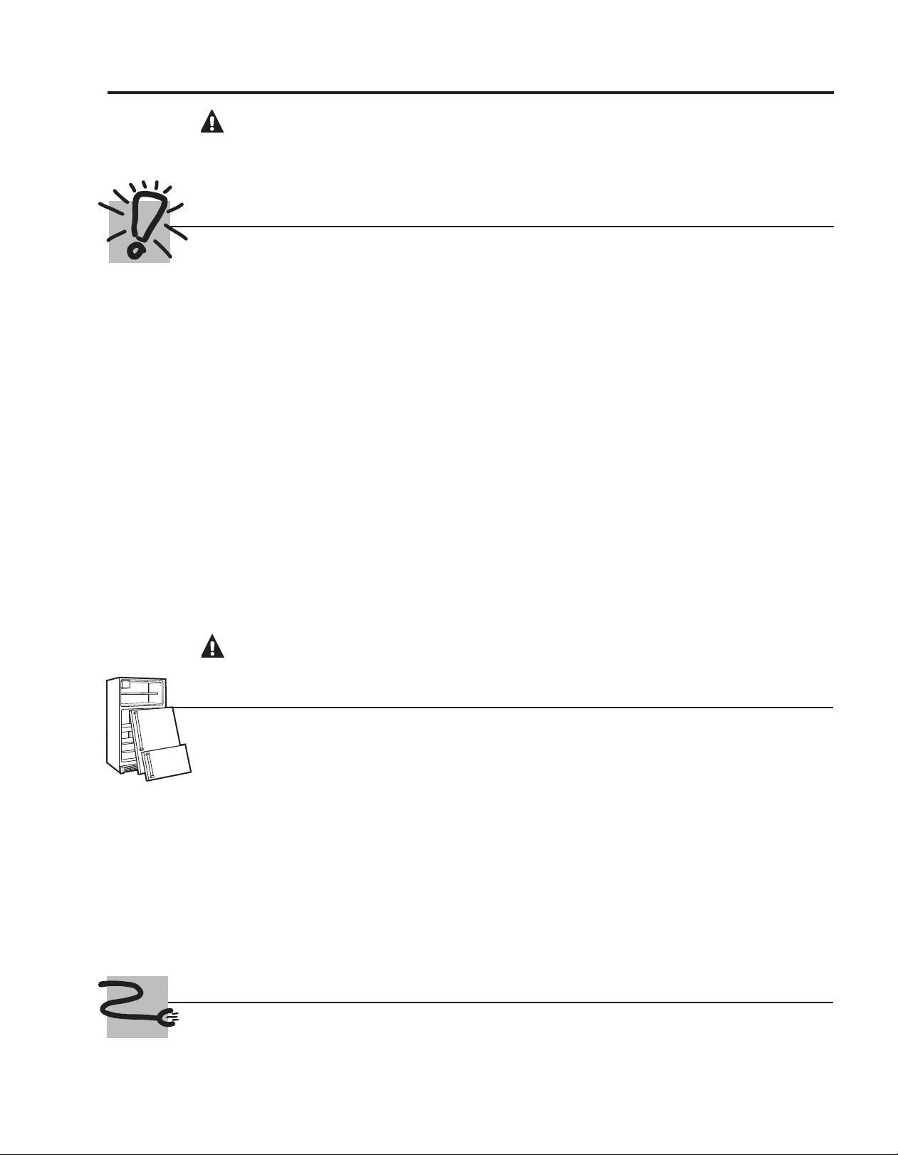
DANGER! RISK OF CHILD ENTRAPMENT
PROPER DISPOSAL OF THE REFRIGERATOR
Child entrapment and suffocation are not problems of
the past. Junked or abandoned refrigerators are still
dangerous…even if they will sit for “just a few days.” If
you are getting rid of your old refrigerator, please
follow the instructions below to help prevent
accidents.
Before You Thr ow Away Your Old
Refrigerator or Freezer:
Take off the doors.
Leave the shelves in place so that children may not
easily climb inside.
Refrigerants
All refrigeration products contain refrigerants,
which under federal law must be removed prior to
product disposal. If you are getting rid of an old
refrigeration product, check with the company
handling the disposal about what to do.
USE OF EXTENSION CORDS
Because of potential safety hazards under certain conditions, we strongly recommend against
the use of an extension cord.
However, if you must use an extension cord, it is absolutely necessary that it be a UL-listed (in the United States)
or a CSA certified (in Canada), 3-wire grounding type appliance extension cord having a grounding type plug
2
and outlet and that the electrical rating of the cord be 15 amperes (minimum) and 120 volts.
Page 3
GEAppliances.com
WARNING!
HOW TO C ONNECT ELECTRICITY
Do not, under any circumstances, cut or remove the third (ground) prong from the power cord.
For personal safety, this appliance must be properly grounded.
The power cord of this appliance is equipped with a 3prong (grounding) plug which mates with a standard
3-prong (grounding) wall outlet to minimize the
possibility of electric shock hazard from this
appliance.
Have the wall outlet and circuit checked by a qualified
electrician to make sure the outlet is properly
grounded.
Where a standard 2-prong wall outlet is encountered,
it is your personal responsibility and obligation to
have it replaced with a properly grounded 3-prong
wall outlet.
The refrigerator should always be plugged into its
own individual electrical outlet which has a voltage
rating that matches the rating plate.
This provides the best performance and also prevents
overloading house wiring circuits which could cause a
fire hazard from overheated wires.
Never unplug your refrigerator by pulling on the
power cord. Always grip plug firmly and pull straight
out from the outlet.
Repair or replace immediately all power cords that
have become frayed or otherwise damaged. Do not
use a cord that shows cracks or abrasion damage
along its length or at either end.
When moving the refrigerator away from the wall, be
careful not to roll over or damage the power cord.
READ AND FOLLOW THIS SAFETY INFORMATION CAREFULLY.
SAVE THESE INSTRUCTIONS
3
Page 4
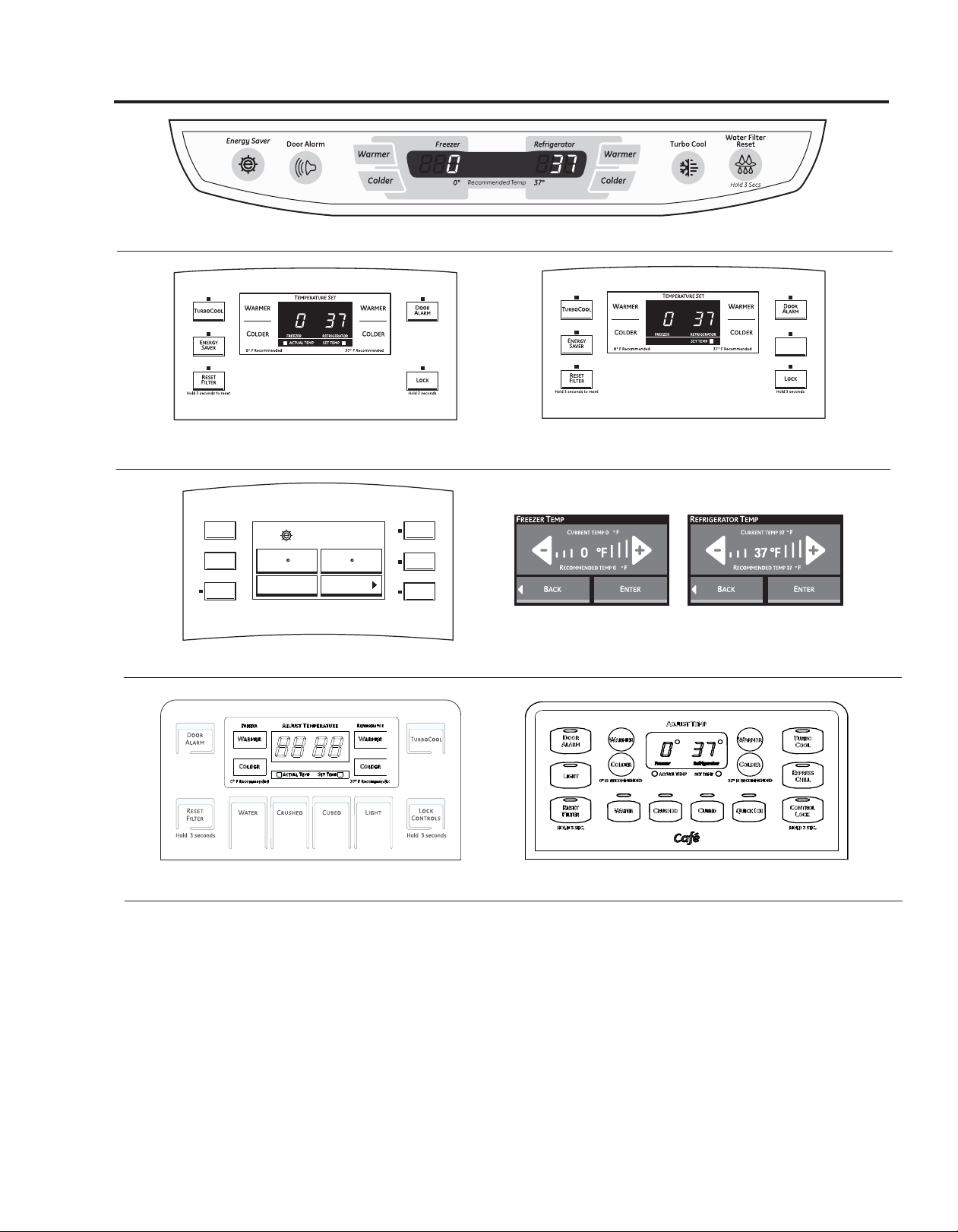
About the controls with temperature settings.
A
CTUAL
T
EMP
Control style A, Internal Controls (on some models)
CTUAL
EMP
H
OME
H
ELP
L
OCK
Hold for 3 Seconds
to activate Lock
(FIG A)
Control styles A, B & D (on some models)
T
URBO
C
E
S
D
A
OOL
NERGY
AVER
OOR
LARM
ENERGY SAVER ON
F
REEZER
P
RECISE FILL
R
EFRIGERATOR
F0
O
F37
PTIONS
Control style C, LCD External Controls (on some models)
(FIG B)
Control style D, External Controls (on some models)
NOTE: The refrigerator is shipped with protective film covering the temperature controls.
If this film was not removed during installation, remove it now.
The temperature controls are preset in the factory at 37°F for the refrigerator compartment and 0°F for
the freezer compartment. Allow 24 hours for the temperature to stabilize to the preset recommended
settings.
The temperature controls can display both the SET temperature as well as the actual temperature in the
refrigerator and freezer. The actual temperature may vary slightly from the SET temperature based on
usage and operating environment.
Setting either or both controls to OFF stops cooling in both the freezer and refrigerator compartments,
but does not shut off electrical power to the refrigerator.
4
Page 5

Changing the Temperature for Control Styles A & B
For Controls on the Door Models:
FIG. “A” To change the temperature, press and release the
WARMERor COLDER pad. The ACTUAL TEMP light will come
on and the display will show the actual temperature. To
change the temperature, tap either the WARMER or COLDER
pad until the desired temperature is displayed.
FIG. “B” To visualize the real temperature press and release
the ACTUAL TEMP pad. The display will show the actual
temperature for 10 seconds.
To change the temperature, tap either the WARMER or
COLDER pad until the desired temperature is displayed. The
SET TEMP light will come on during this process.
For Controls Inside the Refrigerator:
Opening the door displays the actual temperature. To change
the temperature, press either the WARMER or COLDER touch
pads until the desired temperature is displayed.
Changing the Temperature for Control Style C
To Change the Refrigerator Temperature:
Access By: Home > Refrigerator
Activate By: Using the arrows to select the desired temperature.
You must press ENTERto set the new temperature.
To change the Freezer temperature:
Access By: Home > Freezer
Activate By: Using the arrows to select the desired temperature.
You must press ENTERto set the new temperature.
Once the desired temperature has been set, the display will return
to the HOME screen and show the set temperatures underneath
the actual temperature display for several seconds.
Several adjustments may be required. Each time you adjust the
controls, allow 24 hours for the refrigerator to reach the
temperature you have set.
To turn OFF cooling system, tap the WARMER pad for either
refrigerator or freezer until the display shows OFF.
To turn ON cooling system, tap the COLDERpad for either the
refrigerator or freezer twice. The display will show the preset
temperature settings of 37°F for refrigerator and 0°F for freezer.
Turning the cooling system off stops the cooling to refrigerator, but
it does not shut off the electrical power.
Once the desired temperature has been set, the temperature
display will return to the actual refrigerator and freezer
temperatures after 5 seconds. Several adjustments may be
required. Each time you adjust controls, allow 24 hours for the
refrigerator to reach the temperature you have set.
To turn OFF cooling system, tap the WARMERpad for either
refrigerator or freezer until the display shows OFF.
To turn ON cooling system, tap the COLDERpad for either
the refrigerator or freezer twice. The display will show the
preset temperature settings of
freezer.
Turning the cooling system OFF stops the cooling to
refrigerator, but it does not shut off the electrical power.
37°F
for refrigerator and
0°F
for
Changing the Temperature for Control Style D
For Controls on the Door Models:
FIG. “A” To change the temperature, press and release the
WARMERor COLDER pad. The ACTUAL TEMP light
will come on and the display will show the actual
temperature. To change the temperature, tap either the
WARMERor COLDER pad until the desired temperature is
displayed.
FIG. “B” To visualize the real temperature press and release
the ACTUAL TEMP pad. The display will show the actual
temperature for 10 seconds.
To change the temperature, tap either the WARMER or
COLDER pad until the desired temperature is displayed. The
SET TEMP light will come on during this process.
Once the desired temperature has been set, the temperature
display will return to the actual refrigerator and freezer
temperatures after 5 seconds.
Several adjustments may be required. Each time you adjust
controls, allow 24 hours for the refrigerator to reach the
temperature you have set.
To turn OFF cooling system, tap the refrigerator WARMERpad
until display flashes and beeps. Then tap the freezer WARMER
pad until display shows OFF.
To turn ON cooling system, tap the refrigerator COLDER
button twice. The display will show the refrigerator and freezer
set temperatures.
Turning the cooling system off stops the cooling to
refrigerator, but it does not shut off the electrical power.
5
Page 6
About TurboCool.
(on some models)
(on some models)
™
(on some models) GEAppliances.com
How It Works
TurboCool rapidly cools the refrigerator
compartment in order to more quickly
cool foods. Use TurboCool when adding a
large amount of food to the refrigerator
compartment, putting away foods after they
have been sitting out at room temperature
or when putting away warm leftovers. It can
also be used if the refrigerator has been
without power for an extended period.
Once activated, the compressor will turn on
immediately and the fans will cycle on and
off at high speed as needed for eight hours.
The compressor will continue to run until the
refrigerator compartment cools to
approximately 34°F (1°C), then it will cycle on
and off to maintain this setting. After 8 hours,
or if TurboCool is pressed again, the
refrigerator compartment will return to
the original setting.
How to Use
Press TurboCool. The refrigerator
temperature display will show .
After TurboCool is complete, the
refrigerator compartment will return
to the original setting.
NOTES: The refrigerator temperature
cannot be changed during
TurboCool.
The freezer temperature is not
affected during TurboCool.
When opening the refrigerator door
during TurboCool, the fans
will continue to run if they have
cycled on.
(on some models)
(on some models)
(on some models)
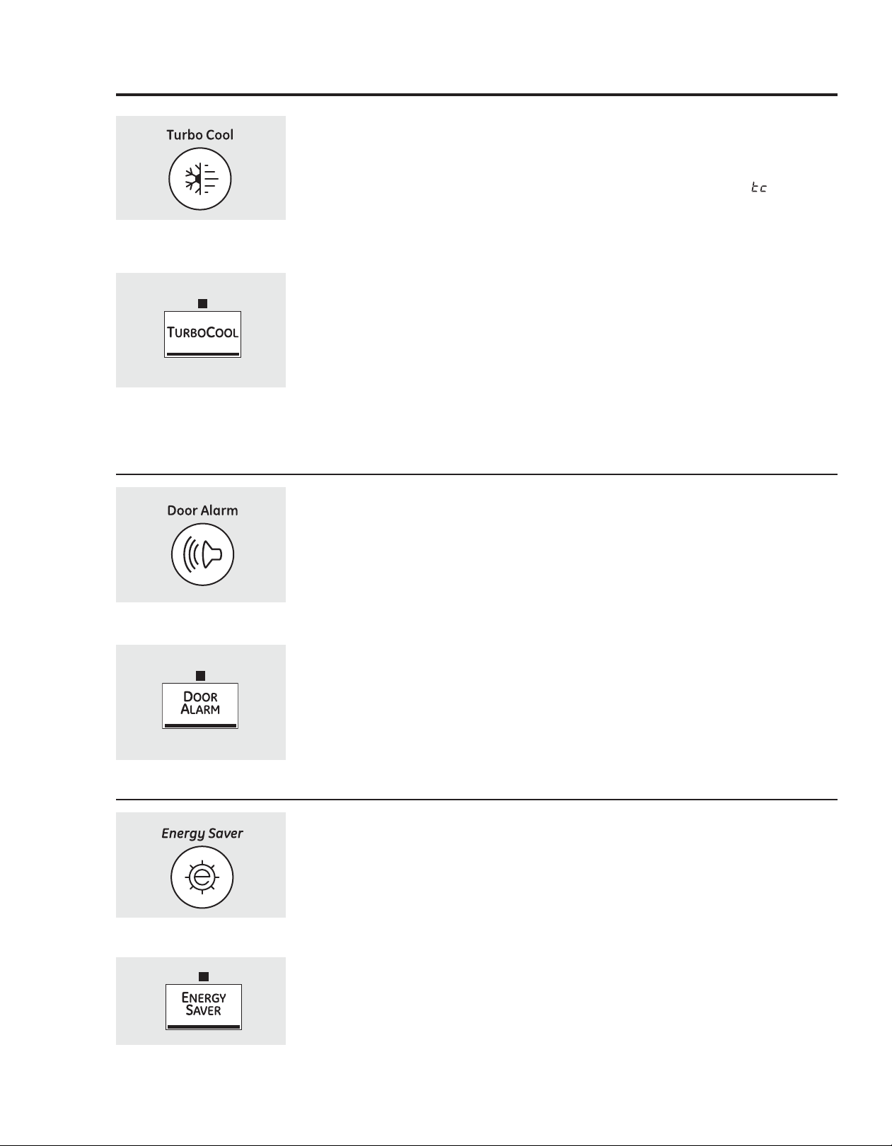
About Door Alarm (on some models)
The door alarm will sound if any door is open
for more than 2 minutes. The beeping stops
when you close the door.
About Energy Saver (on some models)
This product is equipped with an Energy
Saver feature. The refrigerator is shipped with
the Energy Saver feature enabled.
Over time, moisture can form on the front
surface of the refrigerator cabinet and cause
rust. If moisture does appear on the front
surface of the refrigerator cabinet, turn off
the Energy Saver feature by pressing and
releasing the ENERGY SAVERpad on the
control panel.
(on some models)
6
Page 7
About the water filter. (on some models)
Cartridge
Holder
Cartridge
Holder
Water Filter Cartridge
The water filter cartridge is located in the back
upper right corner of the refrigerator
compartment.
When to Replace the Filter
There is a replacement indicator light for the
water filter cartridge on the temperature display.
This light will turn orange to tell you that you
need to replace the filter soon. The filter
cartridge should be replaced when the
replacement indicator light turns red or if the
flow of water to the dispenser or icemaker
decreases.
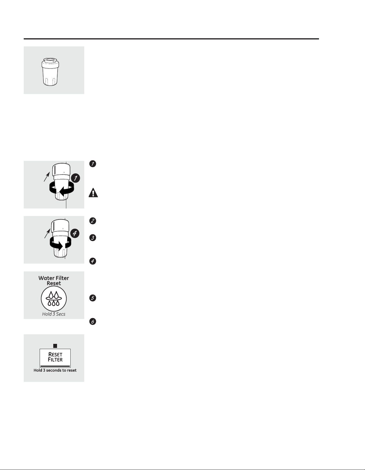
Installing the Filter Cartridge
If you are replacing the cartridge, first
remove the old one by slowly turning it to
the left. DO NOT pull down on the cartridge.
A small amount of water may drip down.
CAUTION: If air has been trapped
in the system, the filter cartridge may be ejected
as it is removed. Use caution when removing.
Remove the protective foil from the end of
the cartridge.
Fill the replacement cartridge with water
from the tap to allow for better flow from the
dispenser immediately after installation.
Lining up the arrow on the cartridge and the
cartridge holder, slowly rotate the cartridge
clockwise until it stops. When the cartridge is
properly installed, you will feel it “click” as it
locks into place. Do not overtighten.
Filter Bypass Plug
You must use the filter bypass plug when a
replacement filter cartridge is not available. The
icemaker will not operate without the filter or
filter bypass plug.
Replacement Filters:
For the maximum benefit of your filtration
system, GE recommends the use of GE branded
SmartWater filters only. Using GE branded filters
in GE and Hotpoint refrigerators provides optimal
performance and reliability. GE branded
SmartWater filters are always the right choice
because they are patented and designed
specifically for GE products. GE SmartWater
filters meet rigorous industry NSF standards for
safety and quality that are important for
products that are filtering your water. GE has
not qualified non-GE branded filters for use in GE
and Hotpoint refrigerators and there is no
assurance that non-GE branded filters meet GE’s
standards for quality, performance and reliability.
To order additional filter cartridges
in the United States, visit our Website,
GEAppliances.com, or call GE Parts and
Accessories, 800.626.2002.
Filter Model MWF
Customers in Canada should consult
the yellow pages for the nearest Mabe Service
Center.
(on some models)
(on some models)
Run 11⁄2 gallons (about 3 minutes) from the
dispenser to clear the system and prevent
sputtering. See To Use the Dispenser section.
Press and hold the RESET WATER FILTER
pad (on some models) for 3 seconds.
NOTE:A newly-installed water filter cartridge
may cause water to spurt from the dispenser.
7
Page 8
About the shelves and bins. GEAppliances.com
Not all features are on all models.
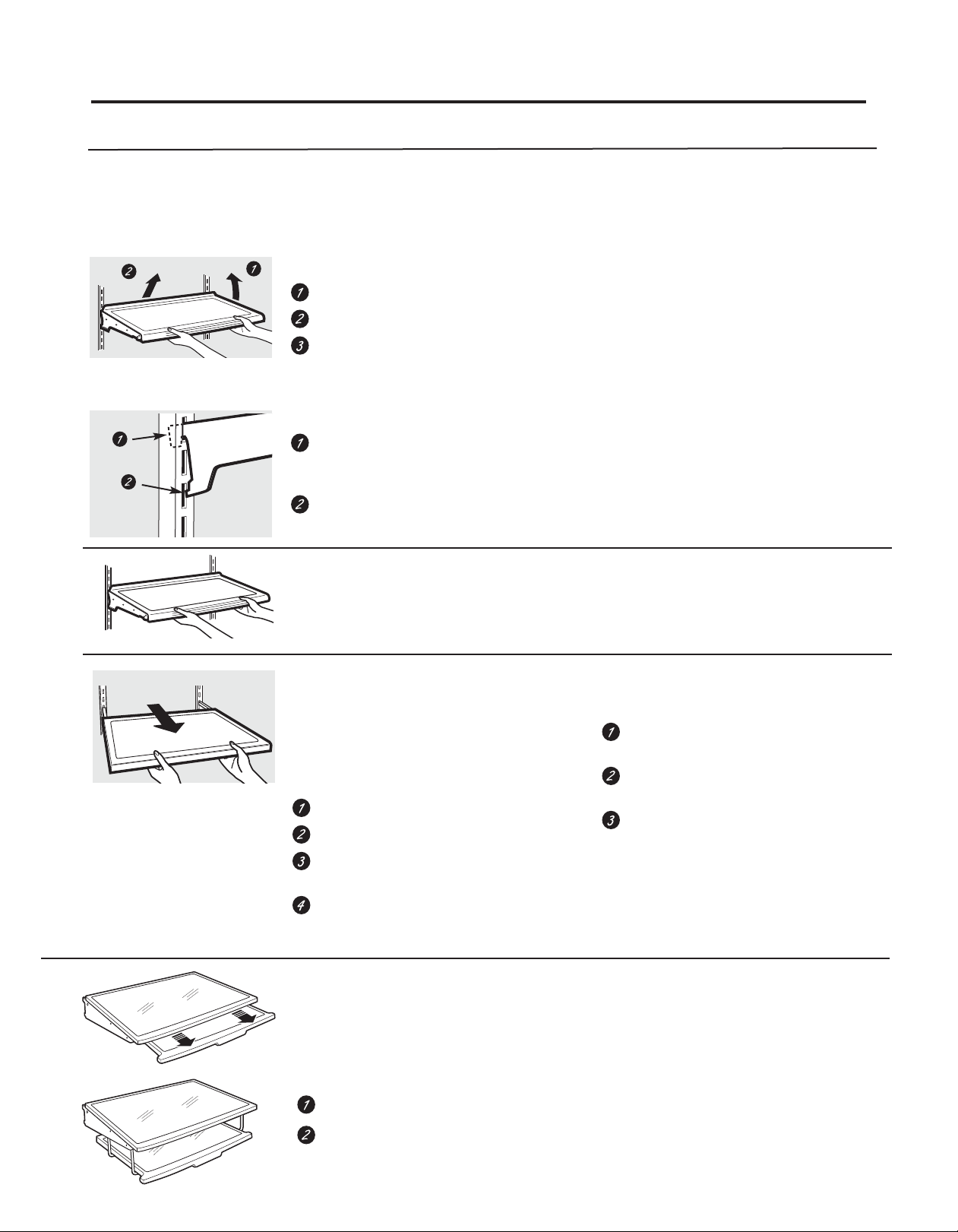
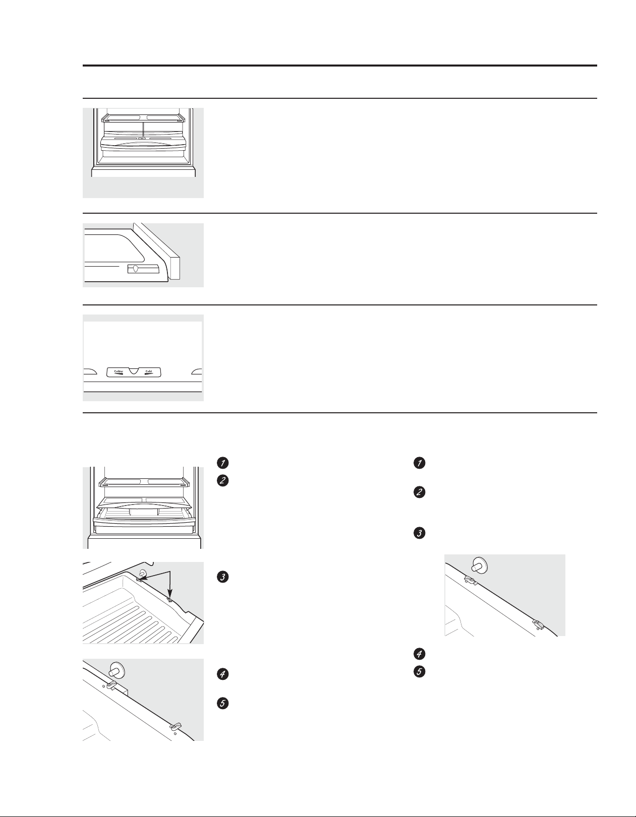
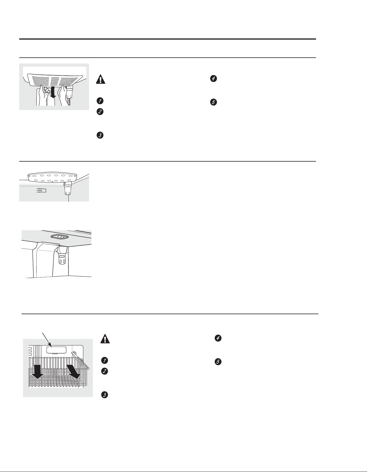
Rearranging the Shelves
Shelves in the refrigerator compartment are adjustable.
Refrigerator Compartment
To remove:
Remove all items from the shelf.
Tilt the shelf up at the front.
Lift the shelf up at the back and bring the
Some models have wire shelves
that can be adjusted in the same
manner.
shelf out.
To replace:
While tilting the shelf up, insert the top
hook at the back of the shelf in a slot on
the track.
Lower the front of the shelf until the
bottom of the shelf locks into place.
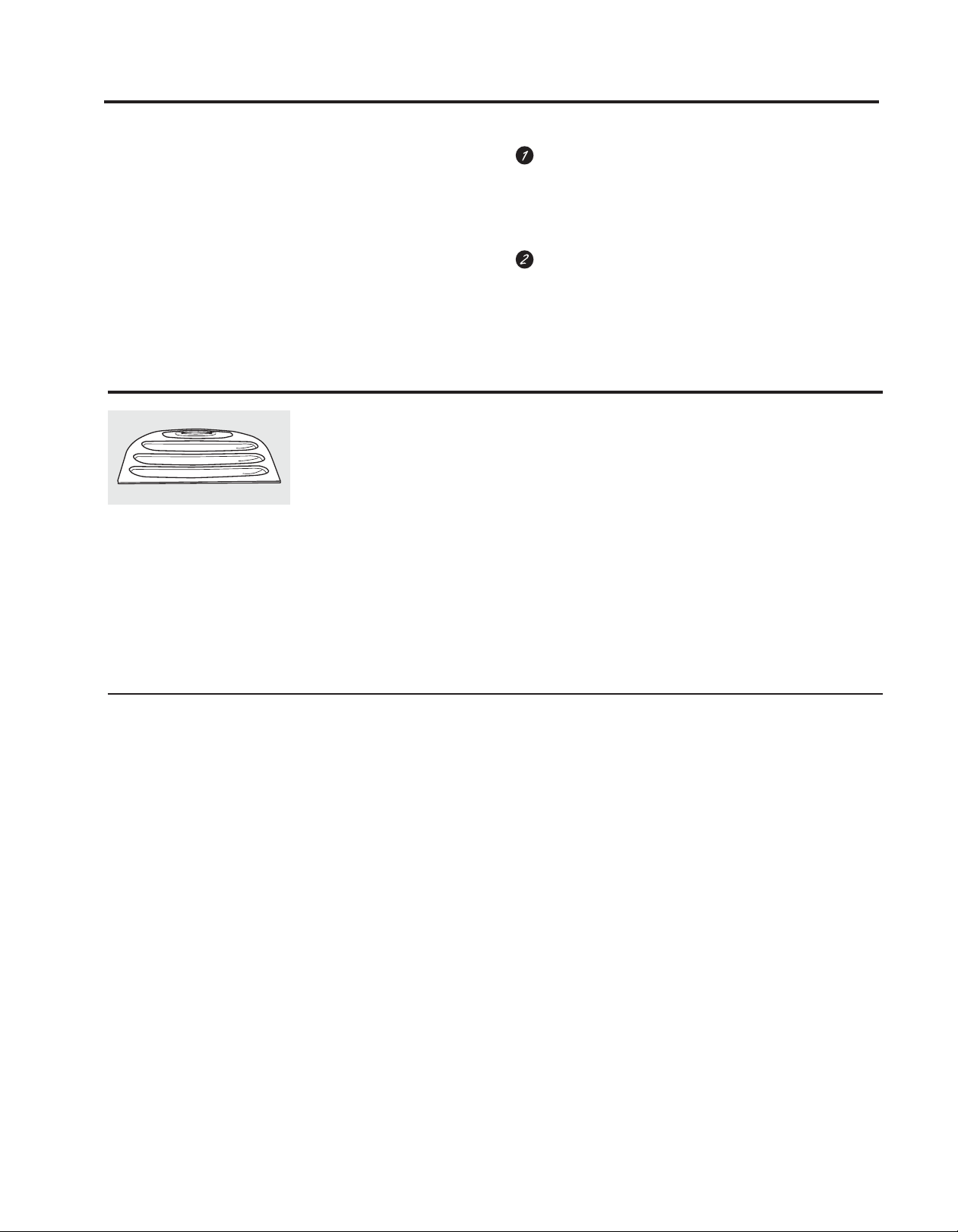
Spillproof Shelves (on some models)
Spillproof shelves have special edges to help prevent spills from dripping to lower shelves. To
remove or replace the shelves, see Rearranging the Shelves.
Slide-Out Spillproof Shelf (on some models)
The slide-out spillproof shelf allows you
to reach items stored behind others. The special
edges are designed to help prevent spills from
dripping to lower shelves.
To remove:
Remove all items from shelf.
Slide the shelf out until it stops.
Lift the front edge of the shelf until the
central tabs are above the front bar.
Continue pulling the shelf forward
until it can be removed.
To replace:
Place the rear shelf tabs just in front of the
central notches on the shelf frame.
Slide the shelf in until the central tabs are
slightly behind the front bar.
Lower the shelf into place until it is
horizontal and slide the shelf in.
Make sure that the shelf sits flat after
reinstallation and doesn’t move freely from side
to side.
Make sure you push the shelves all the way in
before you close the door.
Drop Down Shelf (on some models)
The drop-down shelf gives you the use of another full-size shelf when you need
extra storage. It conveniently folds back out of the way when not in use, giving you
room for storage of larger items.
To use drop-down shelf:
Pull forward and down to drop the shelf into place.
Pull forward while lifting up to place the shelf out of the way.
8
Page 9
About the shelves and bins.
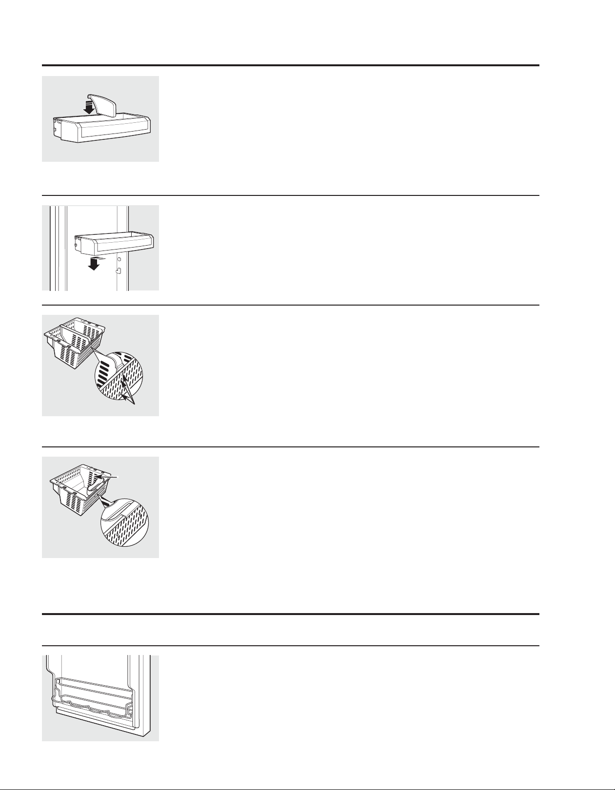
Adjustable Bins on the Door
Tabs
Adjustable bins can easily be carried from
refrigerator to work area.
To remove: Lift bin straight up, then
pull out.
To replace or relocate: Slide in the bin just
above the molded door supports, and push
down. The bin will lock in place.
Non-Adjustable Bins on the Door
To remove: Lift the bin straight up, then
pull out.
To replace: Engage the bin in the molded
supports on the door and push down.
It will lock in place.
Adjustable Divider in Freezer Basket
The freezer basket has a divider that can be
both repositioned or removed.
To remove: Pull the divider forward until the
rear locating tabs are out of the slots. Turn
the divider slightly to the side to release the
front locating tabs and lift out.
To replace: Turn the divider slightly to one
side so the tabs on the front fit into the vent
The snugger helps prevent tipping, spilling
or sliding of small items stored on the door
shelf. Grip the finger hold near the rear of the
snugger and move it to fit your needs.
slots on the basket. Position the divider so
the back locating tabs snap into place in the
back vent slots.
To reposition: Remove the divider. Slide the
divider left or right to the desired location and
replace as instructed above.
Optional Freezer Caddy
Caddy
The optional freezer caddy fits over the front
edge of the bottom freezer basket and can
be removed or added as needed.
To remove:Lift the freezer caddy up.
About the additional features.
Not all features are on all models.
Non-Adjustable Beverage Rack
To remove: Lift the rack straight up, then pull
out.
To replace: Engage the rack in the molded
supports on the door and push down.
It will lock in place.
To replace:Lower the freezer Caddy ensuring
the hook fits over the front edge of the
bottom freezer basket. Push down to secure.
9
Page 10
About the crispers and pans. GEAppliances.com
Not all features are on all models.
Fruit and Vegetable Crisper
Excess water that may accumulate in the
bottom of the drawers or under the drawers
should be wiped dry.
Adjustable Humidity Crisper (on some models)
Slide the control all the way to the
HIGH setting to provide high humidity
recommended for most vegetables.
Location of controls may vary, but function remain the same.
Slide the control all the way to the LOW
setting to provide lower humidity levels
recommended for most fruits.
Adjustable Temperature Deli Pan (on some models)
Slide the control all the way to the left for the
coldest temperature.
How to Remove and Replace the Deli Pan
To remove:
Remove the fruit and vegetable drawers.
Pull the drawer out to the stop position.
To replace:
Make sure all four swing locks are in the
unlock position.
Place the sides of the drawer into the
drawer supports, making sure the swing
locks fit on the drawer slots.
Lock all four swing locks by rotating them
to the lock position.
10
Swing Locks
Lift the lid to access the 4 swing locks.
Rotate all four swing locks to the unlock
position.
Lift the front of the drawer up and out.
Lower the lid and slide in the drawer.
Replace the fruit and vegetable drawers.
Page 11
About the freezer.
Not all features are on all models.
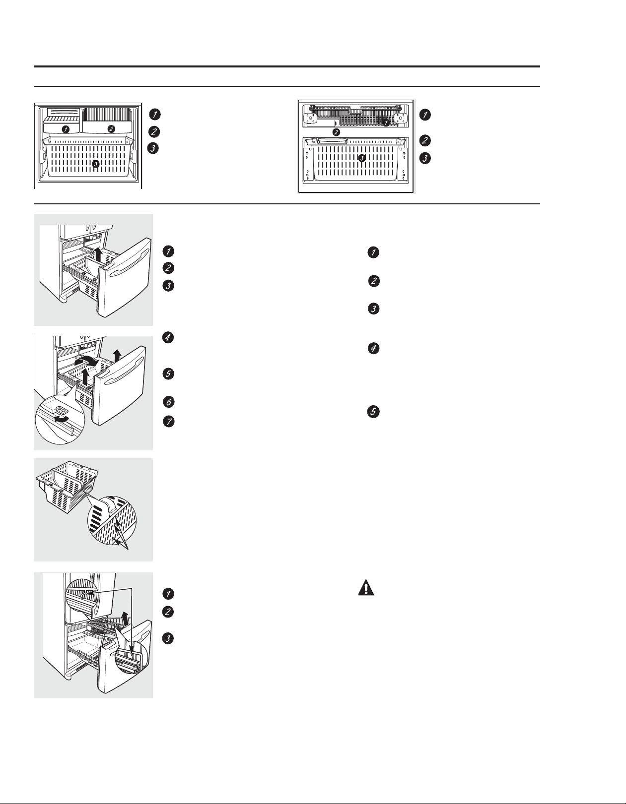
Single Drawer Models
Freezer Shelves and Baskets
Double Drawer Models
Freezer Shelves and Baskets
Appearance and features may vary
A shelf above the ice storage bin
A half-width basket
A deep full-width basket with
divider
Appearance and features may vary
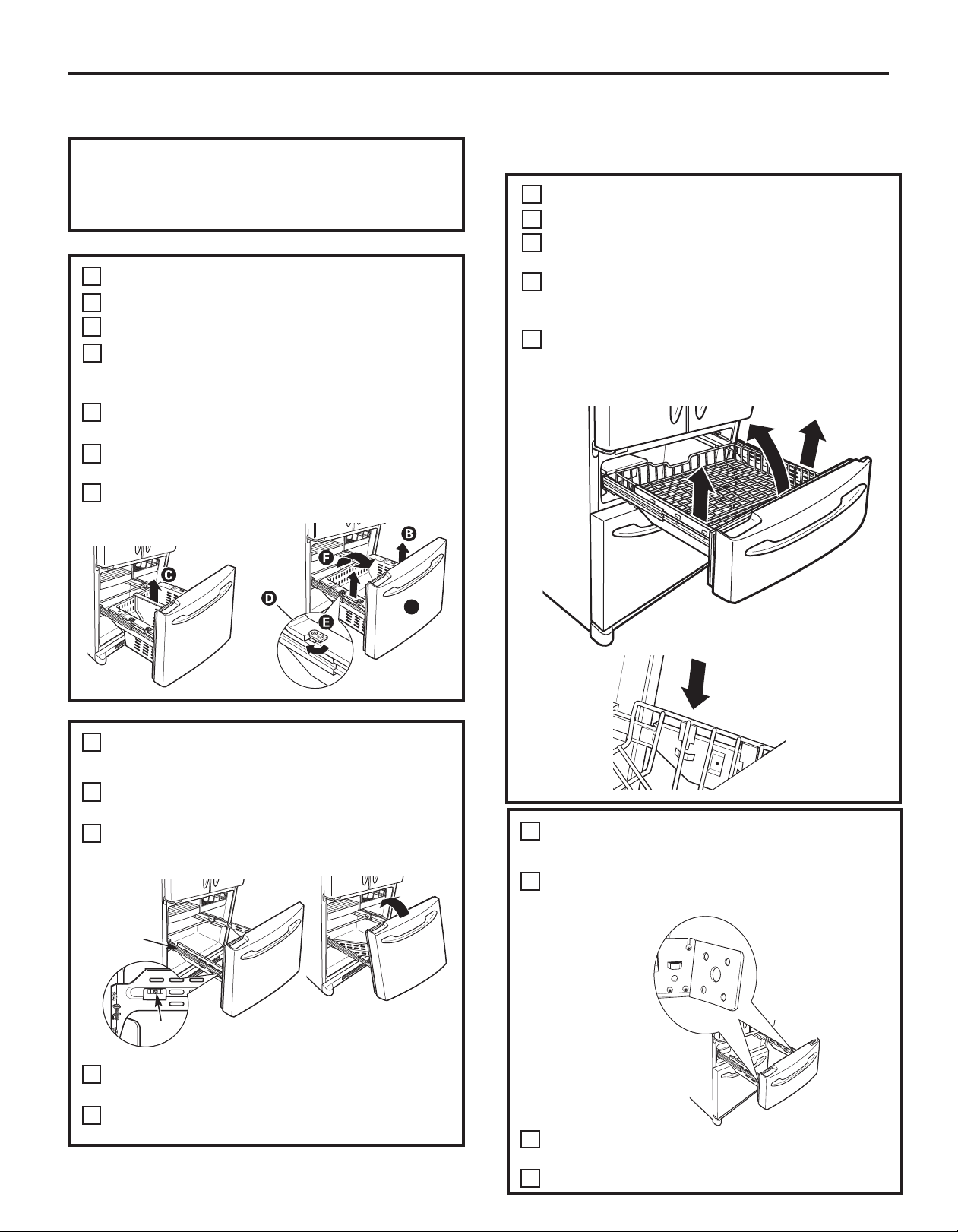
Basket Removal
To remove the deep full-width basket:
Open the freezer drawer until it stops.
Lift the freezer caddy up.
Pull the divider forward until the rear
locating tabs are out of the slots. Turn the
divider slightly to the side to release the
front locating tabs and lift out.
The freezer basket rests on the metal slide
brackets and is held in place with swing
locks.
Turn the swing locks from verticall to
horizontal position.
Open the refrigerator doors.
Lift the basket up and rotate it toward you.
Slide out from the side of the drawer.
A full-width upper basket in top
drawer
Ice Bucket
A deep full-width lower basket in
bottom drawer
When replacing the deep full-width basket:
Tilt the basket toward you and lower it
into the drawer.
Place the basket onto the metal slide
brackets and over the swing locks.
Turn the swing locks from horizontal to
vertical position to lock the basket
in place.
Turn the divider slightly to one side so the
tabs on the front fit into the vent slots on
the basket. Position the divider so the back
locating tabs snap into place in the back
vent slots.
Lower the freezer caddy ensuring the hook
fits over the front edge of the bottom
freezer basket. Push down to secure.
Appearance may vary
Tabs
Tabs
To remove the half-width basket:
Pull the basket out to the stop location.
Lift the basket up at the front to release it
from the slides.
Lift the back up and out of the slide.
CAUTION:Always be sure to
fully close this basket.
When replacing the basket, make sure that
the wire tabs and wire hooks on the sides
of the basket go into the slots in the top
of the upper basket slides.
11
Page 12
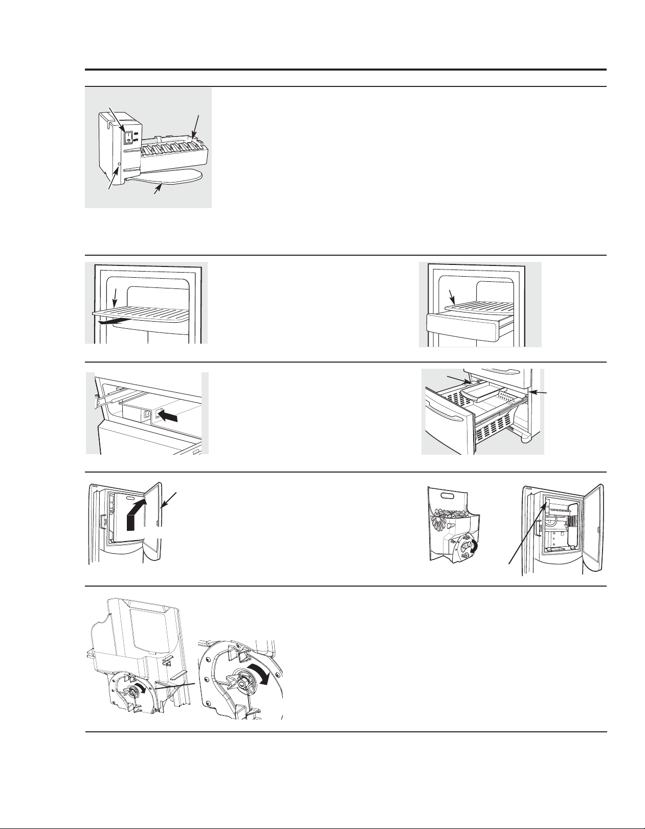
About the automatic icemaker. GEAppliances.com
A newly installed refrigerator may take 12 to 24 hours to begin making ice.
Power
Switch
Green
Power Light
Shelf
Feeler Arm
Ice Bin
Icemaker
Automatic Icemaker (on some models)
The icemaker will produce seven cubes per cycle—
approximately 100–130 cubes in a 24-hour period,
depending on freezer compartment temperature, room
temperature, number of door openings and other use
conditions.
See below for how to access ice and reach the power
switch.
If the refrigerator is operated before the water
connection is made to the icemaker, set the power
switch in the O (off) position.
When the refrigerator has been connected to the water
supply, set the power switch to the l (on) position. The
icemaker power light will turn green when the freezer light
switch is pressed in or when the freezer door is closed.
The icemaker will fill with water when it cools to 15°F
(–10°C). A newly installed refrigerator may take 12 to 24
hours to begin making ice cubes.
Accessing Ice and Reaching the Power
Switch
To reach the icemaker power switch, pull the shelf
above the ice bin straight out, Always be sure to replace
the shelf.
To access ice, simply pull the bin forward.
(Single Drawer Models)
You will hear a buzzing sound each time
the icemaker fills with water.
Throw away the first few batches of ice to allow the
water line to clear.
Be sure nothing interferes with the sweep
of the feeler arm.
When the bin fills to the level of the feeler arm, the
icemaker will stop producing ice. It is normal for several
cubes to be joined together.
If ice is not used frequently, old ice cubes will become
cloudy, taste stale and shrink.
NOTE:In homes with lower-than-average water pressure,
you may hear the icemaker cycle multiple times when
making one batch of ice.
NOTE:Set the power switch to the O (off) position if the
water supply is shut off.
Shelf
Ice Bin
To reach the power switch.
Lift and pull
To reach the power switch.
Ice Box Door
Accessing Ice and Reaching the Power
Switch (Double Drawer Models)
To reach the icemaker power switch,
open the top freezer drawer and remove the full-width
basket. Always be sure to replace the basket.
To access ice, open the bottom freezer drawer. The ice
bucket is located below the mullio. Pull it foward to
access the ice.
Accessing Ice and Reaching the Power
Switch
To reach the icemaker power switch and access Ice,
open the Ice box door located on the refrigerator door
and remove the bucket.
(Ice & Water Models)
Ice Bucket and Dispenser
• Pull up and out on the ice bucket to remove it from the compartment .
• To replace the ice bucket, set it on the guide brackets and push until
the ice bucket seats properly.
• If bucket cannot be replaced, rotate the Ice Bucket Fork 1/4 turn
clockwise.
To access ice.
Ice Bucket
Mullion
To access ice.
Power switch
12
Extra Ice Storage
• There is additional ice storage in the freezer compartment drawer.
Icemaker Accessory Kit
If your refrigerator did not come already equipped with an automatic icemaker, an icemaker accessory kit is available at extra cost.
Check the back of the refrigerator for the specific icemaker kit needed for your model.
Page 13
About the ice and water dispenser. (on some models)
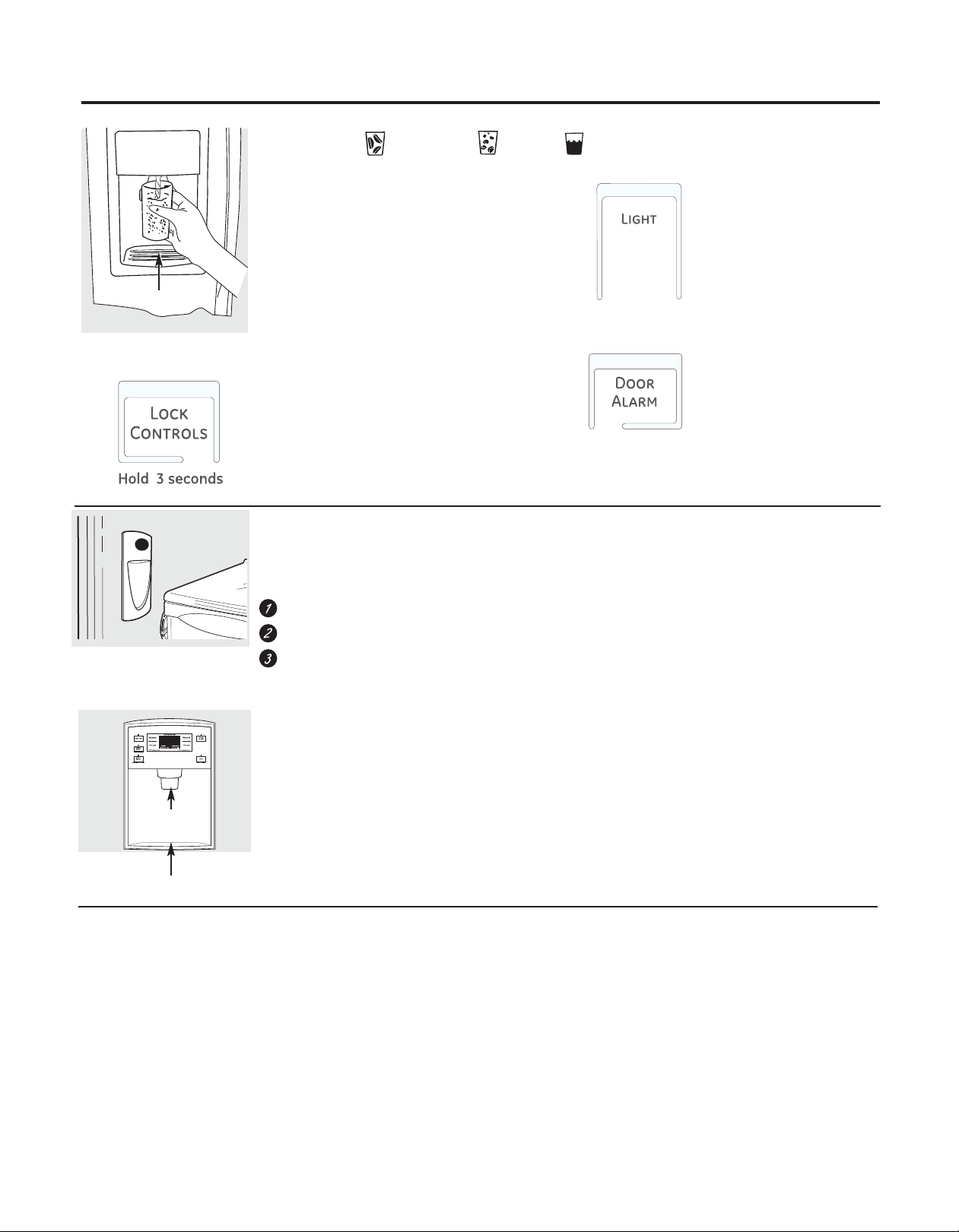
To Use the External Dispenser (on some models)
Spill Shelf
Select CUBED ICE ,CRUSHED ICE or WATER.
Press the glass gently against the top of the
dispenser cradle.
The spill shelf is not self-draining. To reduce water
spotting, the shelf and its grille should be cleaned
regularly.
If no water is dispensed when the refrigerator is
first installed, there may be air in the water line
system. Press the dispenser arm for at least two
minutes to remove trapped air from the water
line and to fill the water system. To flush out
impurities in the water line, throw away the first
six glassfuls of water.
CAUTION: Never put fingers or any other
objects into the ice crusher discharge opening.
Locking the Dispenser
Press the Lock Controls pad for 3 seconds to lock the dispenser and
control panel. To unlock, press and hold the pad again for 3 seconds.
To Use the Internal Water Dispenser (on some models)
The water dispenser is located on the left wall inside the
refrigerator compartment.
To dispense water:
Hold the glass against the recess.
Push the water dispenser button.
Hold the glass underneath the dispenser for 2–3
seconds after releasing the dispenser button. Water
may continue to dispense after the button is released.
If no water is dispensed when the refrigerator is first
installed, there may be air in the water line system. Press the
dispenser button for at least 2 minutes to remove trapped
air from the water line and to fill the water system. During
this process, the dispenser noise may be loud as the air is
purged from the water line system. To flush out impurities in
the water line, throw away the first 6 glassfuls of water.
NOTE: To avoid water deposits, the dispenser should be
cleaned periodically by wiping with a clean cloth or
sponge.
Dispenser Light
This pad turns the night light in
the dispenser on and off. The
light also comes on when the
dispenser cradle is pressed. If
this light burns out, it should be
replaced with a 6 watt 12V
maximum bulb.
Door Alarm (on some models)
To set the alarm, press this pad
until the indicator light comes
on. This alarm will sound if
either door is open for more
than 3 minutes. The light goes
out and the beeping stops
when you close the door.
To Use the External Water Dispenser
Press the glass gently against the top of the dispenser
cradle.
The spill shelf is not self-draining. To reduce water spotting,
the shelf should be cleaned regularly.
Dispenser Cradle
Spill Shelf
If no water is dispensed when the refrigerator is first
installed, there may be air in the water line system. Press
the dispenser arm and run 11⁄2 gallons to remove trapped
air from the water line and to fill the water system. To
flush out impurities in the water line, throw away the first
six glassfuls of water.
Important Facts About Your Dispenser
Do not add ice from trays or bags to
the storage drawer. It may not crush or dispense well.
Avoid overfilling glass with ice and use
of narrow glasses. Backed-up ice can jam the chute or cause
the door in the chute to freeze shut. If ice is blocking the
chute, poke it through with a wooden spoon.
Beverages and foods should not be quick-chilled in the ice
orage drawer. Cans, bottles or food packages in the
st
storage drawer may cause the icemaker or auger to jam.
To keep dispensed ice from missing the glass, put the glass
close to, but not touching, the dispenser opening.
(on some models)
Locking the Dispenser
Press the LOCK pad for 3 seconds to lock the dispenser
and control panel. To unlock, press and hold the pad
again for 3 seconds.
Door Alarm
To set the alarm, press the DOOR ALARM pad. The indicator
light will illuminate. This alarm will sound if either door is
open for more than 2 minutes. The beeping stops when you
close the door.
Some crushed ice may be dispensed
even though y
occasionally when a few cubes accidentally get directed to
the crusher.
After crushed ice is dispensed, some water may drip from
the chut
Sometimes a small mound of snow will form on the door in
the ice chute. This condition is normal and usually occurs
when you have dispensed crushed ice repeatedly. The snow
will eventually evaporate.
ou selected CUBED ICE. This happens
e.
13
Page 14
About the ice and water dispenser. (cont )
Precise Fill (on some models)
This water dispenser is equipped with a feature called Precise Fill. This
feature allows you to choose a precise amount of water. Units include
ounces, cups, pints or liters.
Models with External Dispensers
Access By: Home > Precise Fill > Set Amount
Activate By: Using the arrow buttons to select the desired amount.
Press MORE UNITS to select between CUPS, OUNCES, PINTS or LITERS.
Press the cup against the cradle and water will begin dispensing. It
will automatically stop when the amount set has been dispensed.
The display will show there is no water left to dispense, then reset.
NOTE:Do not leave the dispenser unattended when water is being
dispensed.
If you would like to stop dispensing water before the specified
amount has been dispensed, just remove the cup from the cradle.
The display will show the amount left to dispense.
Care and cleaning of the refrigerator.
Cleaning the Outside
The dispenser drip area (on some models),
beneath the grille, should be wiped dry. Water
left in this area may leave deposits. Remove
the deposits by adding undiluted vinegar to
Dispenser drip area
the well. Soak until the deposits disappear
or become loose enough to rinse away.
The dispenser cradle (on some models).
Before cleaning, lock the dispenser by
pressing and holding the Lock Controls pad
for 3 seconds. Clean with warm water and
baking soda solution – about a tablespoon
(15 ml) of baking soda to a quart (1 liter)
of water. Rinse thoroughly and wipe dry.
The door handles and trim. Clean with
a cloth dampened with soapy water.
Dry with a soft cloth.
Keep the outside clean. Wipe with a
clean cloth lightly dampened with kitchen
appliance wax or mild liquid dish detergent .
Dry and polish with a clean, soft cloth.
Do not wipe the refrigerator with a soiled
dish cloth or wet towel. These may leave
a residue that can erode the paint . Do not
use scouring pads, powdered cleaners,
bleach or cleaners containing bleach
because these products can scratch
and weaken the paint f inish.
Cleaning the Inside
To help prevent odors, leave an open box of baking soda in the fresh food and freezer compartments.
Unplug the refrigerator before cleaning.
If this is not practical, wring excess moisture out of sponge or cloth when cleaning around switches, lights or controls.
Use warm water and baking soda solution – about a tablespoon (15 ml) of baking soda to a quart (1 liter) of water. This both
cleans and neutralizes odors. Rinse and wipe dry.
Use of any cleaning solution other than that which is recommended, especially those that contain petroleum distillates, can
crack or damage the interior of the refrigerator.
Avoid cleaning cold glass shelves with hot water because the extreme temperature difference may cause them to break .
Handle glass shelves carefully. Bumping tempered glass can cause it to shatter.
Do not wash any plastic refrigerator parts in the dishwasher.
14
Page 15
Replacing the light bulbs.
Turning the control to the 0 (off ) position does not remove power to the light circuit.
Refrigerator Lights (on some models)
CAUTION: Light bulbs may
be hot.
Unplug the refrigerator.
To remove the light shield, grasp the
shield at the back and pull out to release
the tabs at the back.
Rotate the shield down and then forward
to release the tabs at the front of the
shield.
LED Lighting – Module (on some models)
LED Lighting – Individual (on some models)
LED lighting will need to be replaced by an
authorized technician.
NOTE: Appliance bulbs may be ordered from
GE Parts and Accessories, 800.626.2002.
After replacing with an appliance bulb of
the same or lower wattage, replace the
shield.
Plug the refrigerator back in.
Light
Shield
Appearance may vary
Call 1.800.432.2737 in the United States. In
Canada, call 1.800.561.3344
Freezer Light (on some models)
CAUTION: Light bulbs may
be hot.
Unplug the refrigerator.
Remove the freezer basket for access.
The bulb is located at the rear of the
freezer inside a light shield.
To remove, grasp the shield at the top
and pull out to release the tabs at the
bottom.
After replacing with an appliance bulb of
the same or lower wattage, replace the
shield and freezer basket.
Plug the refrigerator back in.
15
Page 16
Trim kits and decorator panels. GEAppliances.com
For panel-required models
Read these instructions completely and carefully.
Before You Begin
Some models are equipped with trim kits that allow you to install door panels . You can order
pre-cut black or white decorator panels from GE Parts and Accessories, 800.626.2002, or you
can add wood panels to match your kitchen cabinets .
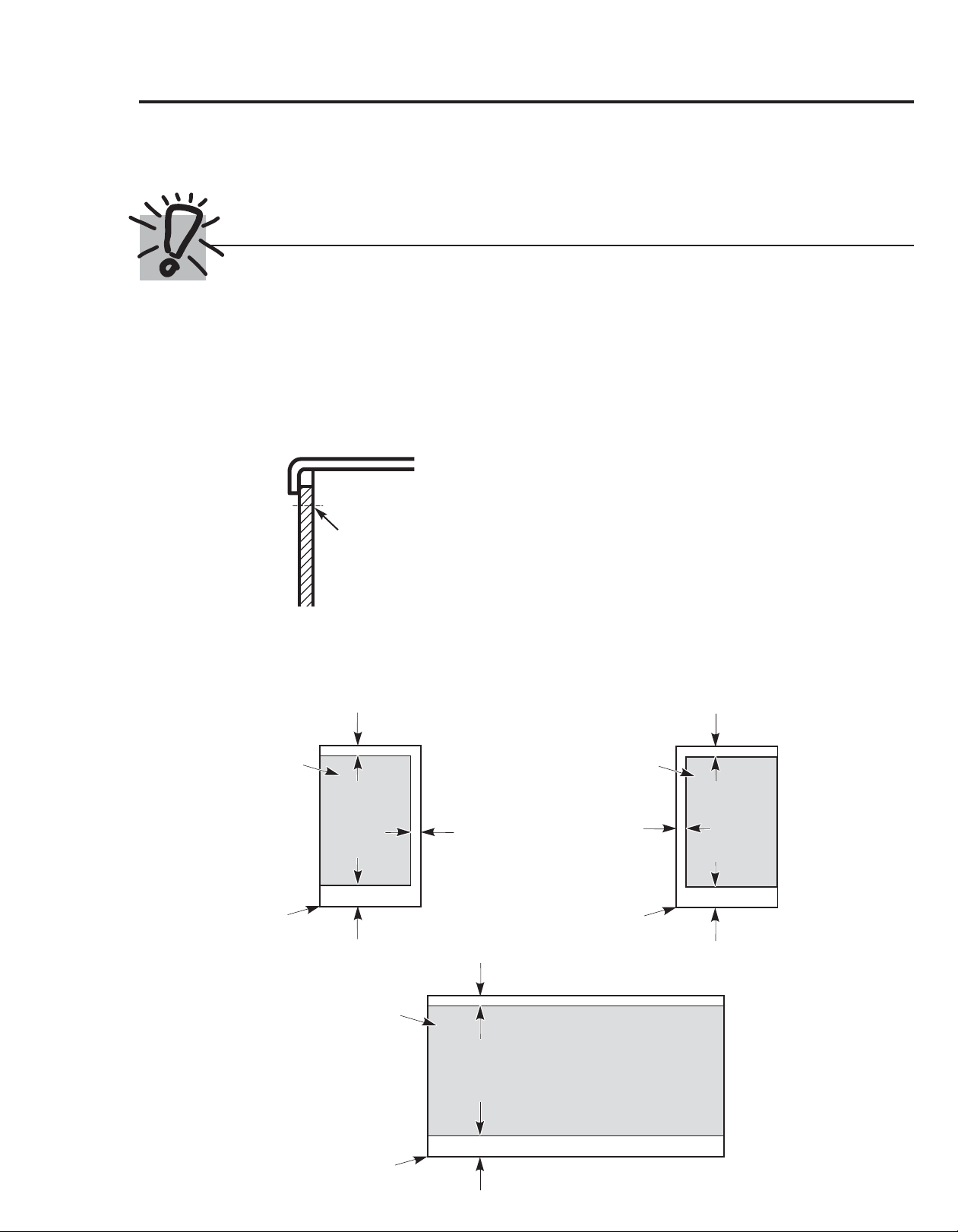
Panels less than 1/4″ (6 mm) thick
When installing wood panels less than 1/4″ (6 mm) thick, you need to create a filler panel, such as 1/8″
cardboard, that will fit between the face of the door and the wood panel. If you are installing the pre-cut
decorator panels, pre-cut filler panels are included in the kit . The combined thickness of the decorator or wood
panel and the filler panel should be 11/32″ (8.7 mm) with the panel itself being no larger than 1/4″ (6 mm).
Panels 1/4” thick or less
1/4” max
The handle and the top and bottom trim stand in front of the surface of the door, which requires that the filler
be smaller in length and width than the panel. Use the guidelines below and tape the filler onto the back of the
panel.
Right Fresh Food Door
Filler
3/4” (19 mm)
3/4” (19 mm)
2 1/2” (63.5 mm)
Filler
Panel
Left Fresh Food Door
3/4” (19 mm)
3/4” (19 mm)
2 1/2” (63.5 mm)
Panel
Freezer Door
16
Filler
3/4” (19 mm)
2 1/2” (63.5 mm)
Panel
Page 17
Trim kits and decorator panels.
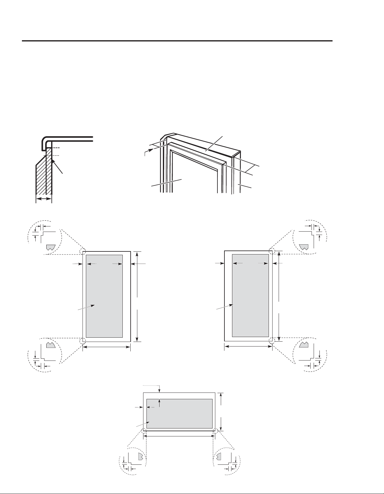
3/4″ (19 mm) or Raised Panel
A raised panel design screwed or glued to a 1/4″ (6 mm) thick backing, or a 3/4″ (19 mm) routed board can be used. The raised
portion of the panel must be fabricated to permit clearances of at least 2″ (5.1 cm) from the handle side for fingertip clearance.
Panels thicker than 1/4″ (6 mm), up to 3/4″ (19 mm) max., will require that the outer 5/16″ (8 mm) of panel perimeter be no
thicker than 1/4″ (6 mm).
Weight limitations for custom panels:
Fresh Food 10 lbs. (4.5 kg) max. for each door
Freezer Door 18 lbs. (8 kg) max.
Panels thicker than 1/4” (6 mm)
5/16” (8 mm)
1/4” (6 mm) max
3/4” (19 mm)
2” (5.1 cm)
Clearance
Handle Side
Appearance
Panel
Dimensions for Custom Wood Panels
1/8
(3 mm)
1/4
(6 mm)
5/16” (8 mm)
minimum at
1/4” (6 mm)
thickness
Top, left and
bottom
Raised portion
of panel
Left Fresh Food Door
38 15/16
(98.9 cm)
2” (51 mm)
minimum at
1/4” (6 mm)
thickness
Handle side
2” (51 mm)
minimum at
1/4” (6 mm)
thickness
Handle side
Raised portion
of panel
1/4” (6 mm)
Thick Backing
3/4”
(19 mm)
Refrigerator
Door
Right Fresh Food Door
1/8”
(3 mm)
1/4”
(6 mm)
5/16” (8 mm)
minimum at
1/4” (6 mm)
thickness
Top, right and
bottom
38 15/16”
(98.9 cm)
1/8”
(3 mm)
1/4”
(6 mm)
16 29/32” (42.9 cm)
2” (51 mm) minimum at
1/4” (6 mm) thickness
Handle side
5/16” (8 mm) minimum at
1/4” (6 mm) thickness
Left, right and
bottom sides
Raised
portion
of panel
1/8”
(3 mm)
1/4”
(6 mm)
Freezer Door
35 29/32” (91.2 cm)
26 3/32”
(66.3 cm)
1/4”
(6 mm)
16 29/32” (42.9 cm)
1/8”
(3 mm)
1/8”
(3 mm)
1/4”
(6 mm)
17
Page 18
Installation
Refrigerator
Instructions
Questions? Call 800.GE.CARES (800.432.2737) or visit our Website at: GEAppliances.com
In Canada, call 1.800.561.3344 or vis i t our Websit e at: www.GEAppliances.ca
BEFORE YOU BEGIN
Read these instructions completely and carefully.
•
IMPORTANT — Save these instructions for local
inspector’s use.
•
IMPORTANT — Observe all governing codes and
ordinances.
• Note to Installer – Be sure to leave these instructions with
the Consumer.
• Note to Consumer – Keep these instructions for future
reference.
• Skill level – Installation of this appliance requires basic
mechanical skills.
• Completion time – Refrigerator Installation
20 minutes
Water Line Installation
30 minutes
Anti-Tip Bracket Installation
20 minutes
• Proper installation is the responsibility of the installer.
• Product failure due to improper installation is not covered
under the Warranty.
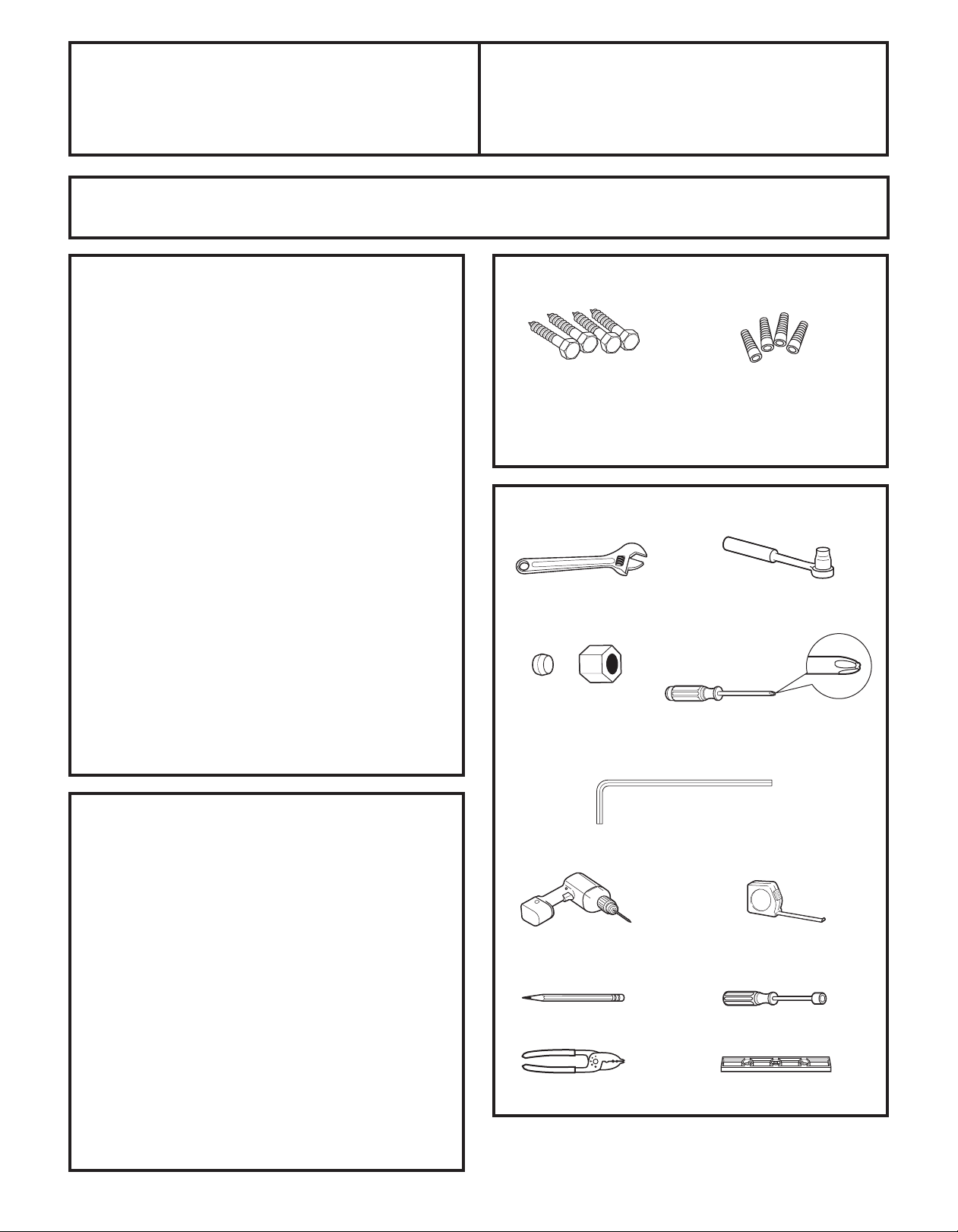
MATERIALS YOU MAY NEED (not included)
Lag Bolts
Drill Bit Appropriate for Anchors
For Anti-Tip Bracket Mounted on CONCRETE Floors Only
TOOLS YOU MAY NEED
Adjustable Wrench
1/4” Outer Diameter
Compression Nut
and Ferrule (sleeve)
(icemaker models only)
Models 21 and 25
Phillips-Head Screwdriver
Anchor Sleeves
3/8” and 5/16” Socket
Ratchet/Driver
PREPARATION
MOVING THE REFRIGERATOR INDOORS
If the refrigerator will not fit through a doorway, the
refrigerator door and freezer drawer can be removed.
• To remove the refrigerator door, see Step 1 in the
Reversing the Door Swing section.
• To remove the freezer drawer, see the Removing the
Freezer Drawer section.
WATER SUPPLY TO THE ICEMAKER AND DISPENSER
(ON SOME MODELS)
If the refrigerator has an icemaker, it will have
to be connected to a cold water line. A GE water supply kit
(containing tubing, shut-off valve, fittings and instructions) is
available at extra cost from
your dealer, by visiting our Website at GEAppliances.com (in
Canada at www.GEAppliances.ca) or from Parts and
Accessories, 800.626.2002 (In Canada 1.800.661.1616).
1/8” Drill Bit and
Electric or Hand Drill
18
Pencil
Wire Cutters
3/32”, 1/8” and 1/4” Allen
wrenches
Tape measure
1/4” Nut Driver
Level
Page 19
Installation Instructions
INSTALLING THE ANTI-TIP FLOOR BRACKET (on 21 ft. models)
LOCATING THE ANTI-TIP
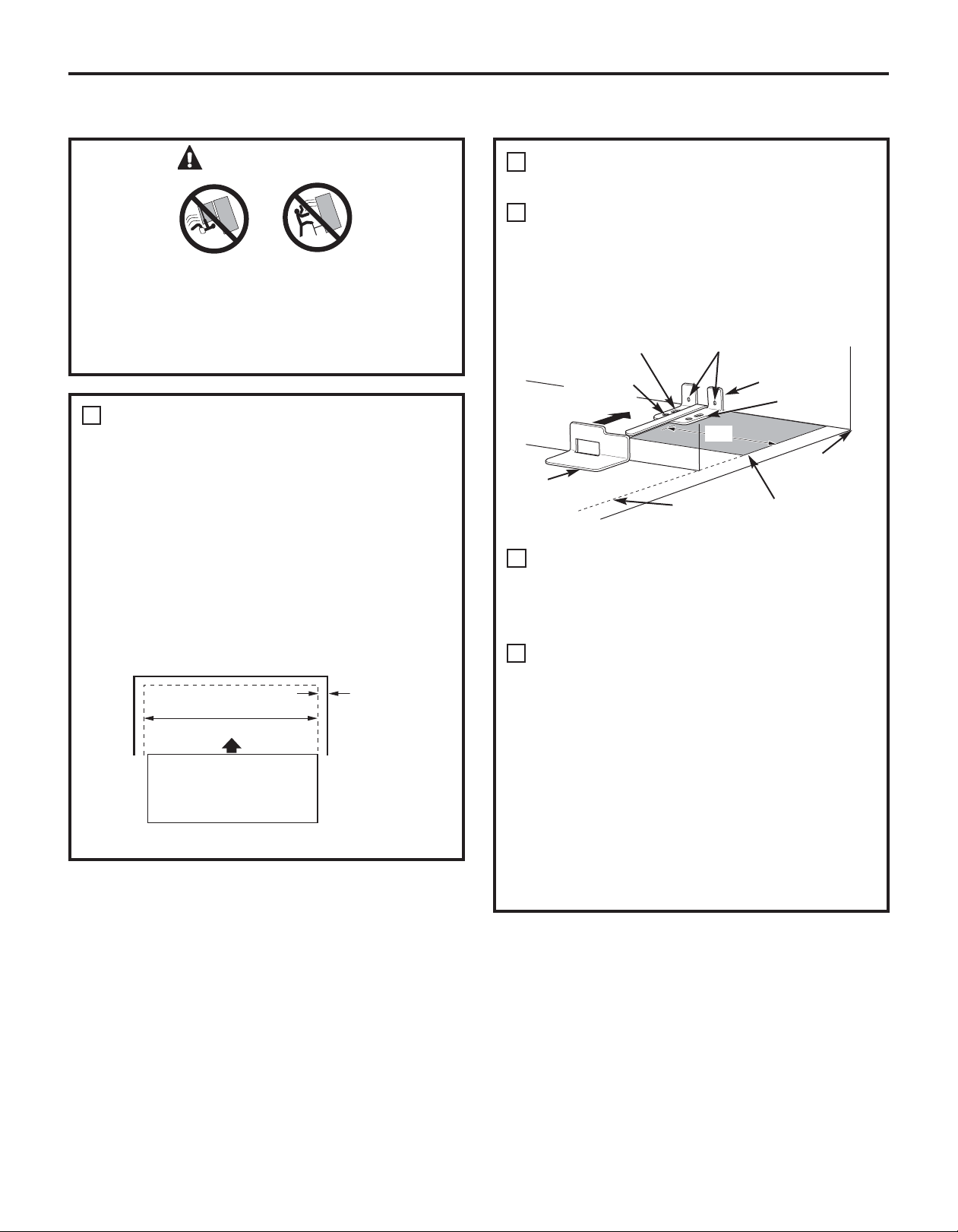
WARNING
Under certain circumstances, this refrigerator
can tip forward.
Injury to persons can result.
Install Anti-Tip Bracket packed with this
refrigerator.
1
MEASURE CABINET OPENING
AVAIL ABLE V S. REFRIGERATOR
WIDTH
Measure width of cabinet opening where
refrigerator will be placed, W.
Be sure to account for any countertop
overhang, baseboard thickness and any
clearance desired. Width, W, should not be less
than 36 inches. The refrigerator will be placed
approximately in the middle of this opening.
Baseboard
Rear Wall
W
REFRIGERATOR
Front
Thickness
or Countertop
Overhang
(Whichever
Is Greater) Plus
Any Desired
Clearance
RH Side
2
FLOOR BRACKET
Place the anti-tip floor bracket locator template
A
(included inside the anti-tip kit) onto the floor
up against the rear wall, within W, and in line
with the desired location of the RH side of the
refrigerator (see Figure 1).
Figure 1 – Installation Overview
Floor – Concrete
(2 Holes)
Floor – Wood
(2 Holes)
Base
Bracket
on the
Refrigerator
Place the anti-tip floor bracket onto the locator
B
template with its RH floor holes lined up with
the floor holes indicated on the template sheet ,
approximately 7
or the RH side of the refrigerator.
Hold down in position and use the anti-tip floor
C
bracket as a template for marking the holes
based upon your configuration and type of
construction as shown in Step 3. Mark the hole
locations with a pencil, nail or awl.
NOTE:
• It is REQUIRED to use at least 2 screws to
mount the floor bracket (one on each side of
the anti-tip floor bracket). Both must be into
either the wall or the floor. Figure 2 indicates
all the acceptable mounting configurations
for screws. Identify the screw holes on the
anti-tip floor bracket for your configuration.
2 Wall Holes
71⁄4″
RH Side of
Refrigerator
1
⁄4″ from the edge of the sheet
Floor Bracket
to Install
RH Holes
Rear RH Corner
of Cabinet Wall
Locator Template
Sheet
19
Page 20
Installation Instructions
2
LOCATING THE ANTI-TIP
FLOOR BRACKET (cont .)
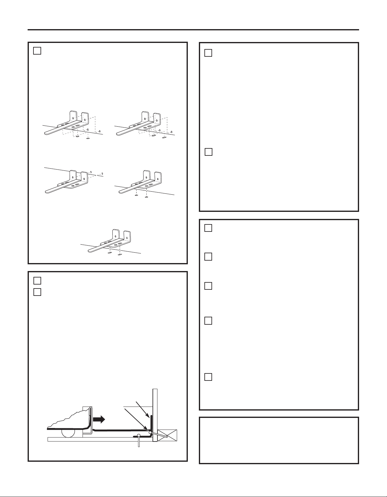
Figure 2 – Acceptable Screw Placement
Locations
Preferred Installation –
Wood
Minimum Acceptable #1 –
Wall Plate Stud
Preferred Installation –
Concrete
Minimum Acceptable #2 –
Wood Floor
CONCRETE Wall and Floor Construction:
B
• Anchors required (not provided):
4 each 1/4” x 1 1/2” lag bolts
4 each 1/2” O.D. sleeve anchors
• Drill the recommended size holes for the
anchors into the concrete at the center of
the holes marked in Step 2.
• Install the sleeve anchors into the drilled
holes. Place the anti-tip floor bracket as
indicated in Step 2. Remove the locator
template from the floor.
• Install the lag bolts through the anti-tip floor
bracket and tighten appropriately.
WOOD Wall and TILE Floor Construction:
C
• For this special case, locate the 2 wall holes
identified in Fig. 1. Drill an angled 1/8” pilot
hole (approx. as shown in Fig. 3) in the center
of each hole.
• Mount the anti-tip floor bracket using the
Minimum Acceptable Installation #1, as
illustrated in Fig. 2.
Minimum Acceptable #3 –
Concrete Floor
ANTI-TIP BRACKET INSTALLATION
3
WOOD Wall and Floor Construction:
A
• Drill the appropriate number of 1/8” pilot
holes in the center of each floor bracket hole
being used (a nail or awl may be used if a drill
is not available) AND remove the locator
template from the floor.
• Mount the anti-tip floor bracket by fastening
the 2, or preferably 4, #10-16 hex-head
screws tightly into place as illustrated in
Figure 3.
Figure 3 – Attachment to
Wall and Floor
Rear RH Corner of
the Refrigerator
2 Screws
Must Enter
Wood or
Metal Stud
Floor
Floor
Bracket
Wall
Wall
Plate
Stud
4
POSITIONING THE REFRIGERATOR
TO ENGAGE THE ANTI-TIP FLOOR
AND BASE BRACKETS
Before pushing the refrigerator into the
A
opening, plug the power cord into the
receptacle and connect waterline (if equipped).
Check for leaks.
Locate the refrigerator’s RH side and move
B
back approximately in line with the RH side of
the cabinet opening, W. This should position the
anti-tip floor bracket to engage the anti-tip
base bracket on the refrigerator.
Gently roll the refrigerator back into the cabinet
C
opening until it comes to a complete stop.
Check to see if the refrigerator front lines up
with the cabinet front face. If not, carefully rock
the refrigerator forward and backward until
engagement occurs and you notice that the
refrigerator is fully pushed up against the rear
wall.
OPTIONAL: Adjust the rear (and front) wheel
D
height settings to fully engage the rear anti-tip
brackets, while also aligning the refrigerator
front with the cabinet front face.
NOTE:
If you pull the refrigerator out and away from the
wall for any reason, make sure the anti-tip floor
bracket is engaged when the refrigerator is pushed
back against the rear wall.
20
Page 21
Installation Instructions
INSTALLING THE REFRIGERATOR
REFRIGERATOR LOCATION
• Do not install the refrigerator where the temperature will
go below 60°F (16°C) because it will not run often enough
to maintain proper temperatures.
• Do not install the refrigerator where the temperature will
go above 100°F (37°C) because it will not perform properly.
• Install it on a floor strong enough to support it fully loaded.
CLEARANCES
Allow the following clearances for ease of installation, proper
air circulation and plumbing and electrical connections.
Standard Depth Counter Depth
Models Models
Sides 1/8″ (3 mm) 1/8″ (3 mm)
Top 1″ (25 mm) 1″ (25 mm)
Back 1″ (25 mm) 1/2″ (13 mm)
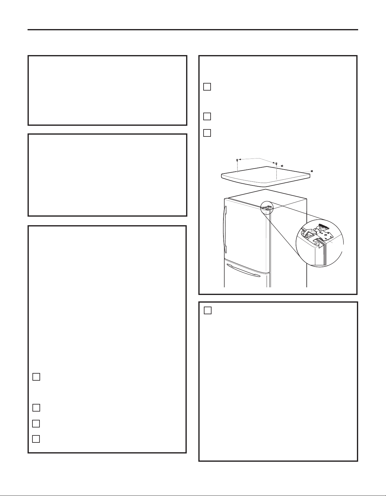
REMOVE TOP CAP (on some models)
•
IMPORTANT NOTE: This refrigerator is 34-1/2″ deep.
Doors and passageways leading to the installation
location must be at least 36″ wide in order to leave the
doors and handles attached to the refrigerator while
transporting it into the installation location. If
passageways are less than 36″, the refrigerator doors
and handles can easily be scratched and damaged.
The top cap and doors can be removed to allow the
refrigerator to be safely moved indoors. Start with Step A.
• If it is not necessary to remove doors, skip Step A. Leave
tape and all packaging on doors until the refrigerator is
in the final location.
• SKID REMOVAL: Tilt refrigerator to each side to remove
skid.
• NOTE: Use a padded hand truck to move this refrigerator.
Place the refrigerator on the hand truck with a side
against the truck. We strongly recommend that TWO
PEOPLE move and complete this installation.
Locate and remove the two Phillips head screws on the
A
top of the refrigerator. Remove the two screws on each
side at the rear of the top cap.
Lift off and remove top cap.
Remove the fresh-food door. Refer to Steps 1 through 3
B
of “Reversing the Door Swing” section.
Remove the bottom freezer drawer. Refer to “Removing
C
Freezer Drawer” section.
Move refrigerator to the installation location.
D
REMOVE TOP CAP (cont.) (on some models)
REINSTALL DOORS, DRAWERS AND TOP CAP
Carefully lower the door onto the center hinge. Reinstall
E
top hinge. NOTE: Ensure the door is properly aligned to
the case top to avoid readjustment of the door during
top cap reinstallation.
F
Place cap over the top of the refrigerator. Reinstall the
original screws in the top and back of the cap.
Reinstall the bottom freezer drawer. Refer to “Replacing
G
the Freezer Drawer” section.
A
Top Hinge B
1
CONNECTING THE REFRIGERATOR TO
THE HOUSE WATER LINE
(icemaker and dispenser models)
A cold water supply is required for automatic icemaker
operation. If there is not a cold water supply, you will
need to provide one. See Installing the Water Line
section.
NOTES:
• Before making the connection to the refrigerator, be
sure the refrigerator power cord is not plugged into
the wall outlet.
• If your refrigerator does not have a water filter, we
recommend installing one if your water supply has
sand or particles that could clog the screen of the
refrigerator’s water valve. Install it in the water line
near the refrigerator. If using GE SmartConnect
Refrigerator Tubing Kit , you will need an additional
tube (WX08X10002) to connect the filter. Do not cut
plastic tube to install filter.
™
21
Page 22
Installation Instructions
1
CONNECTING THE REFRIGERATOR TO
THE HOUSE WATER LINE (cont.)
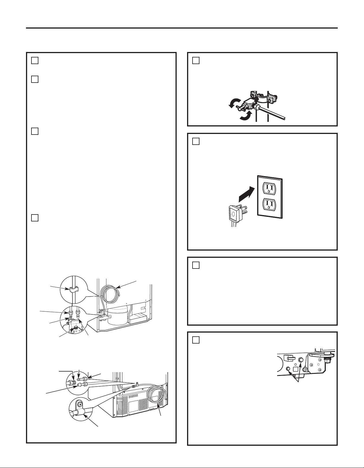
If you are using copper tubing, place a
A
compression nut and ferrule (sleeve) onto the
end of the tubing coming from the house cold
water supply.
™
tubing,
™
If you are using the GE SmartConnect
tubing, the nuts are already assembled to
the tubing.
If you are using copper tubing, insert
B
the end of the tubing into the refrigerator
connection, at the back of the refrigerator, as
far as possible. While holding the tubing,
tighten the fitting.
If you are using GE SmartConnect
insert the molded end of the tubing into the
refrigerator connection, at the back of the
refrigerator, and tighten the compression nut
until it is hand tight. Then tighten one
additional turn with a wrench. Overtightening
may cause leaks.
Fasten the tubing into the clamp provided to
C
hold it in position. You may need to pry open
the clamp.
One of the illustrations below will look like the
connection on your refrigerator.
2
TURN ON THE WATER SUPPLY
(icemaker and dispenser models)
Turn the water on at the shut-off valve (house water
supply) and check for any leaks.
3
PLUG IN THE REFRIGERATOR
On models with an icemaker, before plugging in the
refrigerator, make sure the icemaker power switch is set
to the O (off) position.
See the grounding information attached to the power
cord.
Icemaker-Ready models
Tubing
Clamp
1/4”
Compression
Nut
Ferrule
(sleeve)
Refrigerator
Connection
SmartConnect
Tubing
Icemaker-Installed Models
Refrigerator
Connection
SmartConnect
Tubing
Ferrule
(sleeve)
™
Tubing Clamp
™
1/4”
Compression
Nut
1/4” Copper
Tubing
1/4” Tubing
4
PUT THE REFRIGERATOR IN PLACE
Move the refrigerator to its final location. Make sure the
back side of the refrigerator engages the anti-tip
bracket properly. The anti-tip floor bracket should line
up with the cutout in the back bottom of the
refrigerator, and fit through the cutout when the
refrigerator is pushed into position. (Refer to page 18,
Step 2A for more information.)
5
LEVEL THE REFRIGERATOR
Turn the front roller adjusting
screws clockwise to raise the
refrigerator, counterclockwise
to lower it . Use a 3/8″ hex
wrench with extension, or an
adjustable wrench.
To adjust the rollers on 21
Roller adjusting screws
‘ Counter Depth models:
These models also have rear adjustable rollers
so you can align the refrigerator with your kitchen
cabinets. Use a 3/8″ hex wrench with extension to turn
the screws for the rear rollers—clockwise to raise the
refrigerator, counterclockwise to lower it.
22
Page 23
Installation Instructions
INSTALLING THE REFRIGERATOR (cont.)
7
6
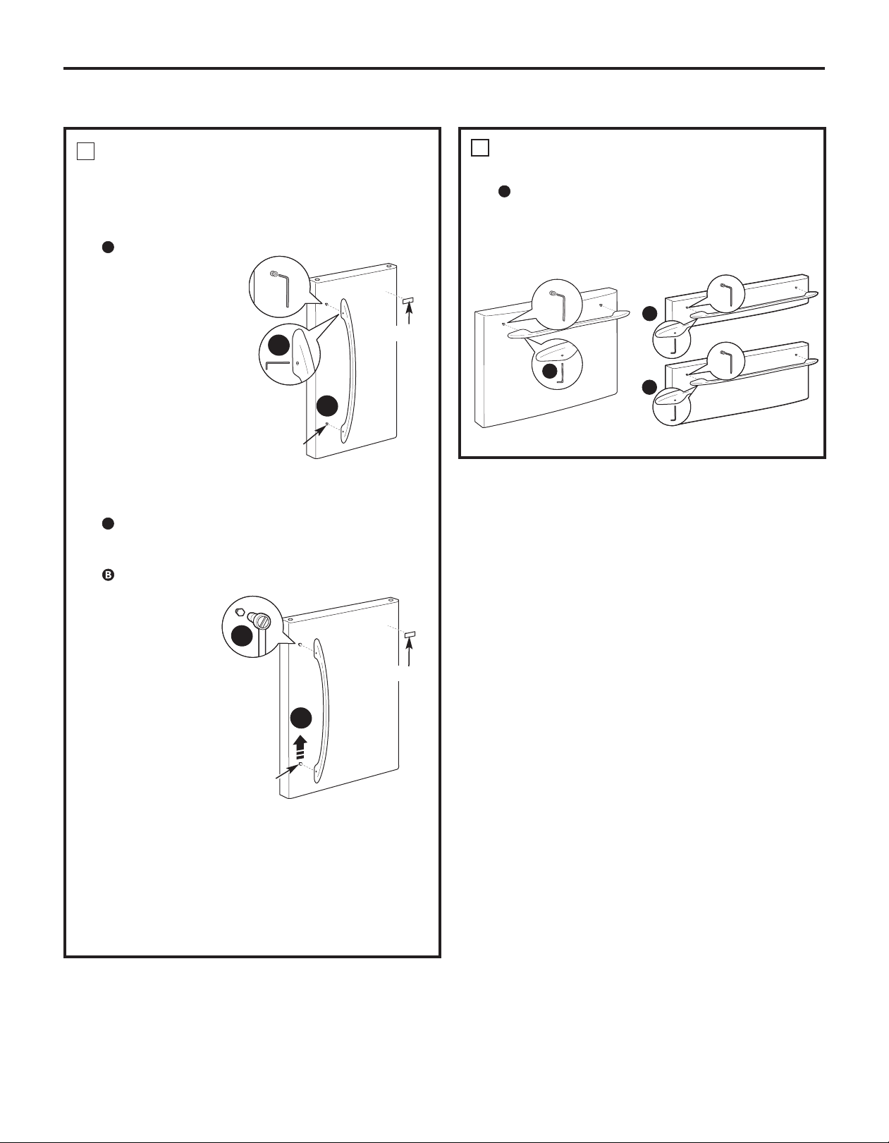
REMOVE THE FRESH FOOD
DOOR HANDLE
(For placement in the installation location or
reversal of the handles – on some models)
Stainless steel (on some models):
A
REMOVING
THE DOOR HANDLE:
Loosen the set screws
with the 3/32″ Allen
wrench
and remove
the handle. NOTE: For
Double Door models
follow the same
procedure on the
opposite door.
A
B
Badge
REMOVE THE FREEZER DOOR HANDLE
Stainless steel and plastic handles:
A
NOTE: If the handle mounting fasteners need to be
tightened or removed, use a 1/4″ Allen wrench.
Loosen the set screws located on the underside of
the handle with a 1/8″ or 3/32″ Allen wrench and
remove the handle.
A
A
A
Mounting
Fasteners
(appearance may vary)
Plastic handle (on some models):
A
REMOVING THE DOOR HANDLE: Depress the tab on
the underside of the handle and slide the handle up
and off of the mounting fasteners.
REVERSING THE DOOR HANDLE (on some models):
• Remove
the handle
mounting
fasteners with
B
a 1/4″ Allen
wrench and
Badge
transfer the
handle
mounting
A
fasteners to the
right side.
• Remove the
logo badge.
Mounting
Fasteners
• Remove and
transfer the
(appearance may vary)
plug button to
the left side of the fresh food door. NOTE: Use a flat
plastic edge to prevent damaging the door. Remove
any adhesive on the door with a mild detergent.
Remove the paper covering on the adhesive
backing on the logo badge prior to carefully
attaching the badge to the door.
(appearance may vary)
(appearance may vary)
23
Page 24
8
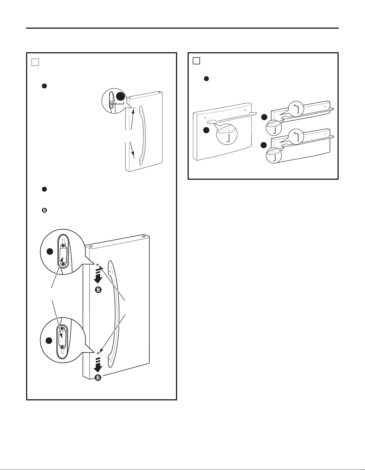
ATTACH THE FRESH FOOD
DOOR HANDLE
Stainless steel handle:
A
Attach the handle
to the handle
mounting fasteners
and tighten the set
screws with a 3/32″
Allen wrench.
NOTE: For Double
Door models follow
the same procedure
on the opposite
door.
Installation Instructions
9
A TTACH THE FREEZER DOOR HANDLE
Stainless steel and plastic handles: (apperance may vary)
A
Attach the handle firmly to the mounting fasteners
and tighten the set screws on the bottom of the
A
Mounting
Fasteners
handle with a 1/8″ or 3/32″ Allen wrench.
A
A
A
(appearance may vary)
Plastic handle:
A
Attach the handle to the handle mounting fasteners
by aligning the slots with the handle mounting
fasteners.
Slide it down until it is firmly locked into position.
A
Slots on back of
handle
Mounting
Fasteners
(appearance may vary)
(appearance may vary)
A
(appearance may vary)
24
Page 25
Installation Instructions
INSTALLING THE REFRIGERATOR (cont.)
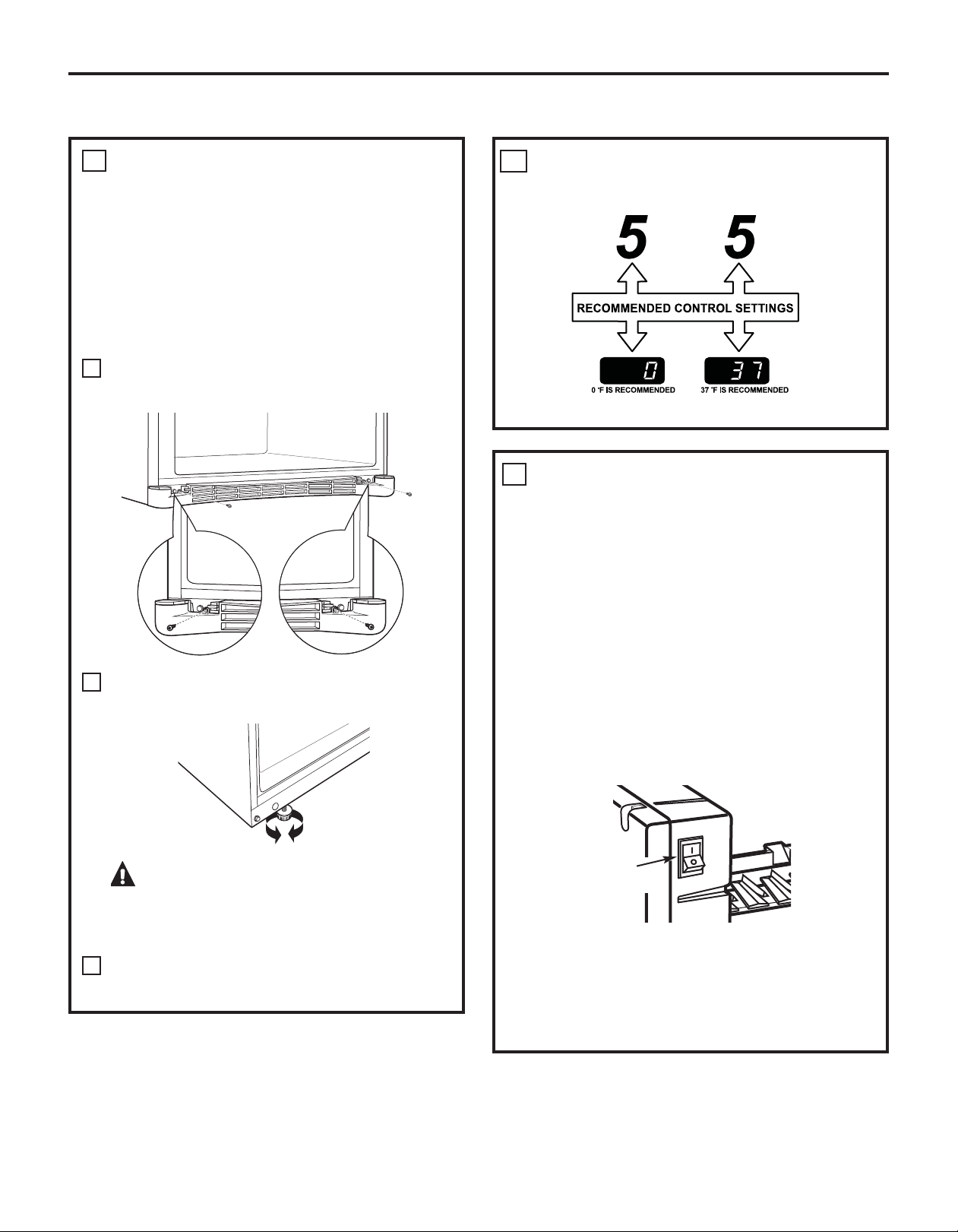
10
LEVEL THE REFRIGERA TOR
The leveling legs have 2 purposes:
1) Leveling legs adjust so the refrigerator is
firmly positioned on the floor and does not
wobble.
2) Leveling legs serve as a stabilizing brake to
hold the refrigerator securely in position
during operation and cleaning. The leveling
legs also prevent the refrigerator from
tipping.
Remove the grille by removing the two Phillips-
A
head screws.
SET THE CONTROLS
11
Set the controls to the recommended setting.
REMOVE PACKAGING START
12
ICEMAKER
A) Remove all tape, foam and protective
B) Remove the tie downs from the freezer
C) Place half width basket onto drawer slides.
(icemaker models)
packing from shelves and drawers.
baskets.
See About the freezer section for
instructions.
Turn the leveling legs clockwise to raise the
B
refrigerator, counterclockwise to lower it.
CAUTION: To avoid possible
personal injury or property damage, the
leveling legs must be firmly t ouching
the floor.
Replace the base grille by inserting the two
C
Phillips-head screws.
Set the icemaker power switch to the I (on)
position. The icemaker will not begin to operate
until it reaches its operating temperature of
15°F (–9°C) or below. It will then begin operation
automatically. It will take 2–3 days to fill the
ice bin.
Power
switch
NOTE:
In lower water pressure conditions, the water
valve may turn on up to 3 times to deliver
enough water to the icemaker.
25
Page 26
Installation Instructions
REMOVING THE FREEZER DRAWER (on some models)
The freezer drawer can be removed, if needed, to fit
through tight areas.
Read these instructions completely and carefully.
1
REMOVE THE BASKET
Open the freezer drawer until it stops.
A
Lift the freezer caddy up
B
Pull the divider forward until the rear locating tabs
C
are out of the slots. Turn the divider slightly to the
side to release the front locating tabs and lift out.
The freezer basket rests on the metal slide
D
brackets and is held in place with swing locks.
Turn the swing locks from vertical to horizontal
E
position. Open refrigerator doors.
F
Lift the basket up and rotate it toward you.
Slide out from the side of the drawer.
.
TOP DRAWER
1
REMOVE THE BASKET
A
Open the freezer drawer until it stops.
Cut the 2 wire ties off of the basket with wire
B
cutters.
Lift the front end of the basket so that the front
C
two alignment tabs come out of the metal slide
brackets first .
Then rotate the front edge of the drawer up
D
while lifting the remaining two rear alignment
tabs out of the metal slide brackets. Pull the
basket up and out of the drawer.
(on Double Drawer Models)
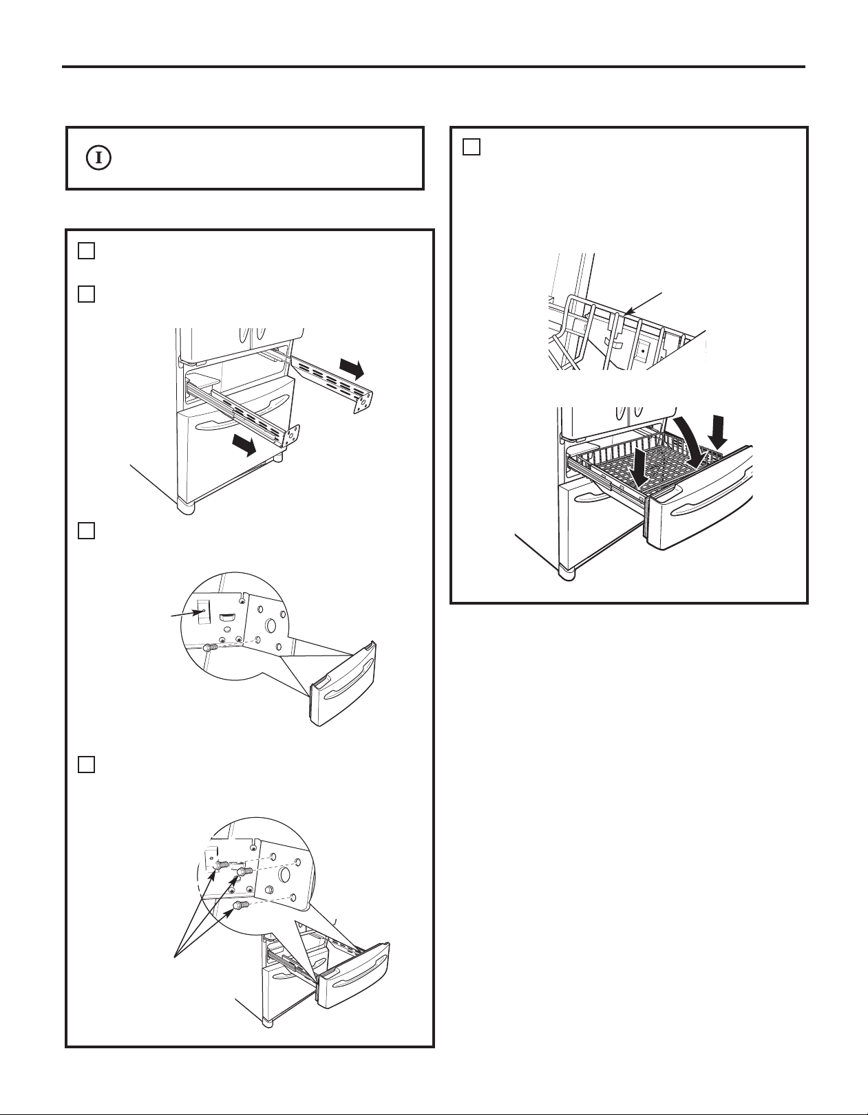
2
REMOVE THE DRAWER FRONT FROM
THE SLIDES
Remove the hex-head screw from each side
A
of the rail assembly.
B
Tilt the drawer front toward the refrigerator
and lift out.
Rail
assembly
Screw
A
REMOVE THE DRAWER FRONT FROM
2
THE SLIDES
A
Remove the 8 hex head screws from the
drawer and remove the drawer.
Set the drawer front on a non-scratching
C
surface.
Push the rail assemblies back into the cabinet.
D
26
Set the drawer front on a non-scratching
B
surface.
C
Push the rail assemblies back into the cabinet.
Page 27
Installation Instructions
REPLACING THE FREEZER DRAWER (on double drawer models)
Two people may be required to complete
this procedure.
TOP DRAWER
ATTA CH AND SECURE THE DRAWER
1
FRONT TO THE SLIDES
Pull out the rail assemblies to the full length on
A
each side of the cabinet.
Drive the bottom outside screw into the drawer
B
on each side until it is all the way in.
REPLACE THE FREEZER BASKET
2
Tilt the basket back and lower it down into
the drawer. Rotate the basket to a horizontal
position and press it down into the 4 alignment
tabs on the rails.
Tab
Screw
Drive the remaining 3 screws on each side
C
all the way into place (there are a total
of 8 hex-head screws).
Screws
27
Page 28
Installation Instructions
REVERSING THE DOOR SWING (on some models)
1
IMPORTANT NOTES
When reversing the door swing:
NOTE: Door swing is not reversible on stainless steel
models.
• Read the instructions all the way through before
starting.
• Parts are included in the door hinge kit.
• Handle parts carefully to avoid scratching paint.
• Set screws down by their related parts to avoid
using them in the wrong places.
• Provide a non-scratching work surface for the doors.
IMPORT ANT: Once you begin, do not move the cabinet
until door-swing reversal is completed.
These instructions are for changing the hinges from
the right side to the left side—if you ever want to
change the hinges back to the right side, follow these
same instructions and reverse all references to left and
right.
• Once door swing is finalized, ensure the logo badge
is properly aligned and permanently secured to
the door by removing the adhesive cover on the
back side.
NOTE: A replacement logo badge is included in the
hinge kit.
Unplug the refrigerator from its electrical outlet.
Empty all door shelves, including the dairy
compartment.
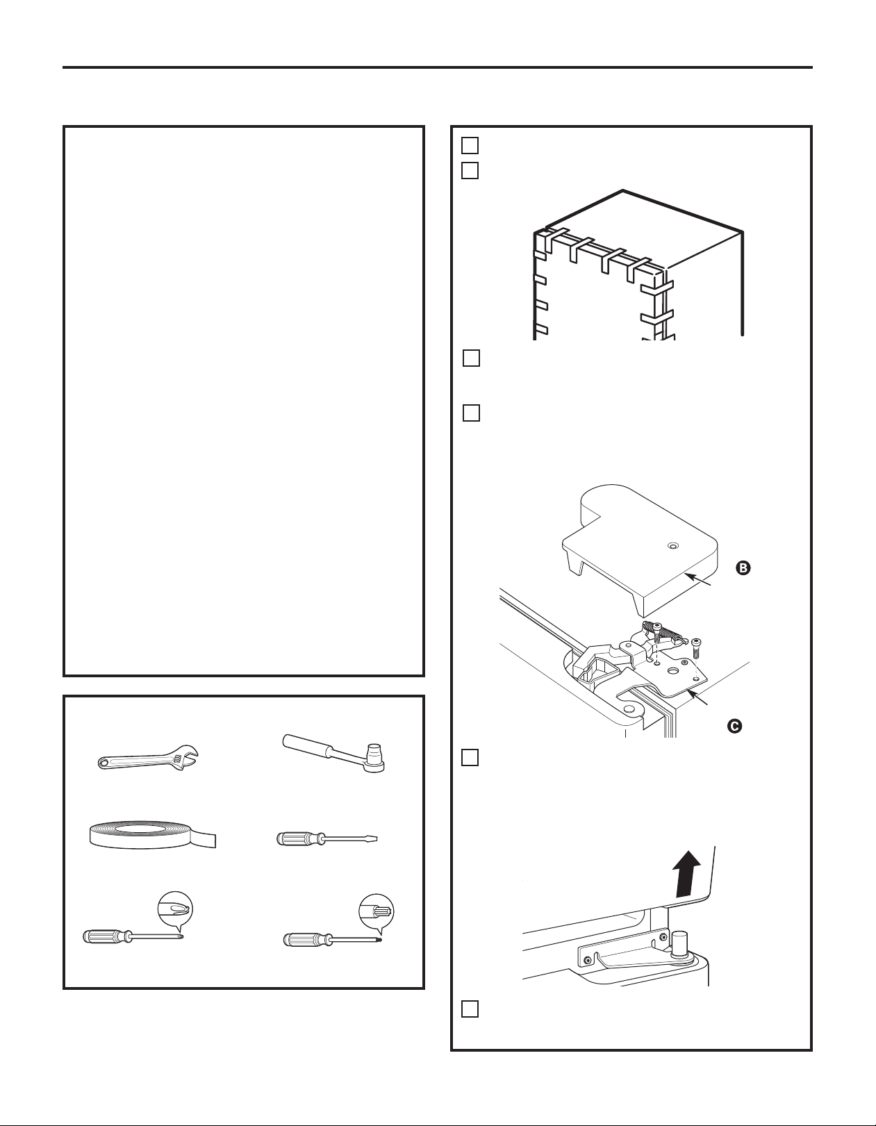
REMOVE THE REFRIGERATOR DOOR
Tape the door shut with masking tape.
A
Remove the hinge cover on top of the
B
refrigerator door by removing the Phillips-head
screws and pulling it up.
Using a 5/16″ socket ratchet/driver, remove the
C
bolts securing the top hinge to the cabinet. Then
lift the hinge straight up to free the hinge pin
from the socket in the top of the door.
Hinge Cover
TOOLS YOU WILL NEED
Adjustable Wrench
Masking Tape
Phillips Screwdriver
5/16” Socket
Ratchet/Driver
Thin-blade Screwdriver
Torx T-20 Driver
28
Top Hinge
Remove the tape and tilt the door away from
D
the cabinet. Lift the door off the center hinge
pin. Ensure that the plastic hinge pin thimble
remains on the hinge pin or inside door hinge
pin hole located in the bottom of the door.
Set the door on a non-scratching surface with
E
the inside up.
Page 29
Installation Instructions
REVERSING THE DOOR SWING (cont.)
2
REMOVE CENTER HINGE
Using a 5/16″ socket ratchet/driver, remove the
bolts securing the center hinge to the cabinet.
Set the hinge and bolts aside.
3
INSTALL CENTER HINGE
Transfer the plug button and screw hole cover
A
in the hinge holes on the left side to the right
side.
4
TRANSFER REFRIGERATOR
DOOR STOP
Remove the door stop on right side of
A
the bottom of the refrigerator door by
removing the two screws.
B
Move the plastic hinge hole thimble to the
opposite hole.
C
Install the door stop on the left side, making
sure to line up the screw holes in the door stop
with the holes in the bottom of the door.
A
Bottom of
Refrigerator Door
(Right Side)
Bottom of
Refrigerator Door
(Left Side)
Install the center hinge from the kit on the left
B
side.
NOTE: A new hinge will be required for the left side
(supplied in the door hinge kit).
5
TRANSFER REFRIGERATOR DOOR
HANDLE TO RIGHT
Refer to Remove the Fresh Food Door Handle
and Attach the Fresh Food Door Handle
sections for instructions.
29
Page 30
Installation Instructions
6
REHANG REFRIGERATOR DOOR
Lower the refrigerator door onto the center
A
hinge pin. Ensure that the plastic hinge pin
thimble is on the center hinge pin or inside
door hinge pin hole located in the bottom of
the door.
Insert the top hinge pin into the hinge hole on
B
top of the refrigerator door. Make sure the door
is aligned with the cabinet. Attach the hinge to
the top of the cabinet loosely with the bolts.
Make sure the gasket on the door is flush
C
against the cabinet and is not folded. Support
the door on the handle side and make sure the
door is straight and the gap between the doors
is even across the front. While holding the door
in place, tighten the top hinge bolts. Replace the
hinge cover.
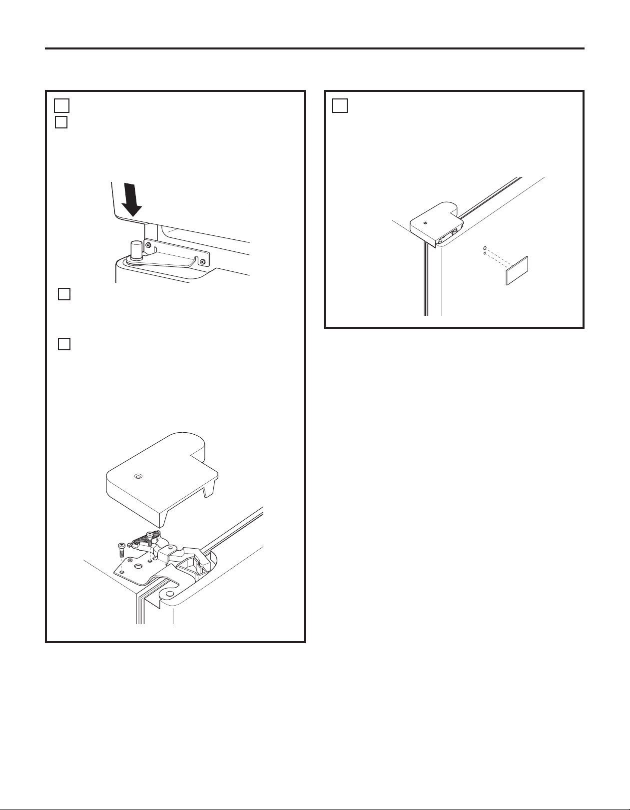
7
INSTALL THE LOGO BADGE
Remove the adhesive backing paper
and align the pins on the back of the badge
with the holes in the door. Apply pressure to
the badge to ensure it sticks to the door.
30
Page 31

Installation Instructions
REMOVING THE DOORS (on some models)
IMPORTANT NOTES
NOTE: Door swing is not reversible.
• Read the instructions all the way through before
starting.
• Handle parts carefully to avoid scratching paint.
• Set screws down by their related parts to avoid
using them in the wrong places.
• Provide a non-scratching work surface for the
doors.
IMPORTANT: Once you begin, do not move the
cabinet.
These instructions are for removing the doors.
Unplug the refrigerator from its electrical outlet.
Empty all door shelves, including the dairy
compartment.
1
REMOVE THE REFRIGERATOR DOORS
Tape the doors shut with masking tape.
A
(for water dispenser models)
Start with right-hand door first: Remove the
B
screw securing the center hinge cover, lift the
hinge cover and place to the side on top of the
refrigerator.
TOOLS YOU WILL NEED
Adjustable Wrench
Masking Tape
Phillips Screwdriver
3/8” and 10 mm Socket
Ratchet/Driver
Thin-blade Screwdriver
Remove hinge cover
(1 Phillips screw)
(for water dispenser models)
Remove water coupling and power coupling.
C
C1
Water Coupling
Remove the metal spring
clip. Use a screwdriver to
push the red plastic locking
clip down and off.
C2
Water Coupling
Push red collar
and hold.
Pull tube.
C3
31
Power Coupling
Black mark
flush with
collar assembly
Pull apart power
coupling to
disconnect
Page 32

Installation Instructions
1
REMOVE THE REFRIGERATOR
DOORS (cont.)
Remove the hinge cover on top of the
D
refrigerator door by removing the Phillips-head
screws and pulling it up.
Using a 5/16″ socket ratchet/driver, remove the
E
bolts securing the top hinge to the cabinet. Then
lift the hinge straight up to free the hinge pin
from the socket in the top of the door.
For Ice and Water models, also disconnect
power cord and ground wire (not shown)
Hinge Cover
Top Hinge
2
REMOVE CENTER HINGE
Using a 5/16″ socket ratchet/driver, remove the
bolts securing the center hinge to the cabinet.
Set the hinge and bolts aside.
3
REMOVE OPPOSITE DOOR
Follow the same procedure on the opposite
door. There are no wires, water lines or center
hinge covers on the opposite side.
4
REMOVE FREEZER DRAWER
Refer to the Removing the Freezer Drawer
section for instructions.
Remove the tape and tilt the door away from
F
the cabinet. Lift the door off the center hinge
pin. Ensure that the plastic hinge pin thimble
remains on the hinge pin or inside door hinge
pin hole located in the bottom of the door.
G
Set the door on a non-scratching surface with
the inside up.
32
Page 33

Installation Instructions
REPLACING THE DOORS (on some models)
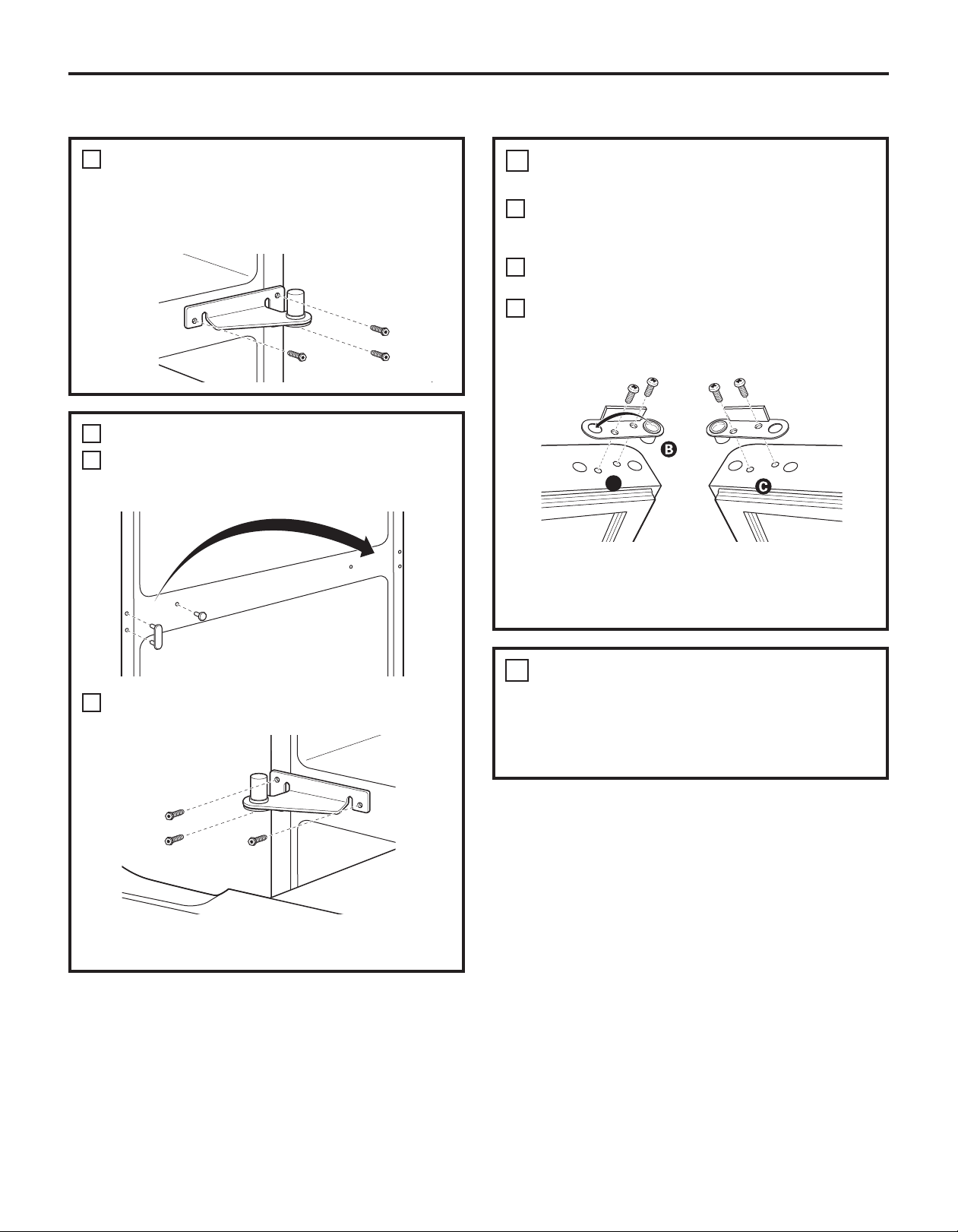
1
INSTALL CENTER HINGE
Install the center hinge on each side.
2
REHANG REFRIGERATOR DOORS
Lower the refrigerator door onto the center
A
hinge pin. Ensure that the plastic hinge pin
thimble is on the center hinge pin or inside
door hinge pin hole located in the bottom of
the door.
Hinge Pin
Securely tape the door shut with masking tape
B
or have a second person support the door.
C
Route wires through bottom right hinge pin slot.
Insert the top hinge pin into the hinge hole on
top of the refrigerator door. Make sure the door
is aligned with the cabinet and opposite door.
Attach the hinge to the top of the cabinet loosely
with the bolts.
2
REHANG REFRIGERATOR DOORS (CONT.)
Make sure the gasket on the door is flush
E
against the cabinet and is not folded. Make sure
the door is straight and the gap between the
doors is even across the front. While holding the
aligned door in place, tighten the top hinge bolts.
Replace the hinge cover and screw.
Hinge Cover
Top Hinge Bolts
(appearance may vary)
3
REPLACE OPPOSITE DOOR
Follow the same procedure on the opposite
door. There is no water line or hinge cover.
4
ALIGN DOUBLE DOORS
If the top of the doors are uneven, first try to
raise the lowest door by turning the leveling leg
on the same side as the door until the doors are
even. If the unit rocks, re-adjust the leveling legs
to the extent that the unit is stable.
If the doors remain uneven, turn the adjustable
Bottom
Right Hinge
Pin Slot
(appearance may vary)
On right-hand doors, pass the wires and water
D
line through the center hinge pin. Then connect
the water line and 4-pin connector.
Center Hinge
Pin
Water Line
4-Pin
Connector
33
pin to raise, or lower, the left door to match the
right door. Use a 1/4″ Allen wrench to turn the
pin.
Adjustable pin
5
REPLACE FREEZER DRAWER
Refer to the Replacing the Freezer Drawer
section for instructions.
Page 34

Installation Instructions
INSTALLING THE WATER LINE (ICEMAKER MODELS)
BEFORE YOU BEGIN
Recommended copper water supply kits are WX8X2,
WX8X3 or WX8X4, depending on the amount of tubing
you need. Approved plastic water supply lines are GE
SmartConnect
WX08X10015 and WX08X10025).
When connecting your refrigerator to a GE Reverse
Osmosis Water System, the only approved installation
is with a GE RVKit. For other reverse osmosis water
systems, follow the manufacturer’s recommendations.
If the water supply to the refrigerator is from a
Reverse Osmosis Water Filtration System AND
the refrigerator also has a water filter, use the
refrigerator’s filter bypass plug. Using the
refrigerator’s water filtration cartridge in
conjunction with the RO filter can result in hollow
ice cubes.
This water line installation is not warranted by the
refrigerator or icemaker manufacturer. Follow these
instructions carefully to minimize the risk of
expensive water damage.
Water hammer (water banging in the pipes) in
house plumbing can cause damage to refrigerator
parts and lead to water leakage or flooding. Call a
qualified plumber to correct water hammer before
installing the water supply line to the refrigerator.
To prevent burns and product damage, do not hook
up the water line to the hot water line.
If you use your refrigerator before connecting the
water line, make sure the icemaker power switch is
in the O (off ) position.
Do not install the icemaker tubing in areas where
temperatures fall below freezing.
When using any electrical device (such as a power
drill) during installation, be sure the device is double
insulated or grounded in a manner to prevent the
hazard of electric shock, or is battery powered.
All installations must be in accordance with local
plumbing code requirements.
™
Refrigerator Tubing (WX08X10006,
WHAT YOU WILL NEED
• Copper or GE SmartConnect™Refrigerator
Tubing kit,1/4″ outer diameter to connect the
refrigerator to the water supply. If using copper, be
sure both ends of the tubing are cut square.
To determine how much tubing you need: measure
the distance from the water valve on the back of
the refrigerator to the water supply pipe. Be sure
there is sufficient extra tubing to allow the
refrigerator to move out from the wall after
installation.
™
GE SmartConnect
available in the following lengths:
6’ (1.8 m) – WX08X10006
15’ (4.6 m) – WX08X10015
25’ (7.6 m) – WX08X10025
Refrigerator Tubing Kits are
34
Page 35

Installation Instructions
INSTALLING THE WATER LINE (CONT.)
Install the shut-off valve on the nearest frequently
WHAT YOU WILL NEED (CONT.)
NOTE: The only GE approved plastic tubing
is that supplied in GE SmartConnect
Refrigerator Tubing kits. Do not use any other
plastic water supply line because the line is
under pressure at all times. Certain types of
plastic will crack or rupture with age and cause
water damage to your home.
• A GE water supply kit (containing tubing, shut-off
valve and fittings listed below) is available at
extra cost from your dealer or from Parts and
Accessories, 800.626.2002 (in Canada
1.800.661.1616).
• A cold water supply. The water pressure must be
between 20 and 120 p.s.i. (1.4–8.1 bar).
• Power drill.
• 1/2″ or adjustable wrench.
• Straight and Phillips-blade screwdriver.
™
used drinking water line.
1
2
SHUT OFF THE MAIN WATER SUPPLY
Turn on the nearest faucet long enough
to clear the line of water.
CHOOSE THE VALVE LOCATION
Choose a location for the valve that is easily
accessible. It is best to connect into the side of a
vertical water pipe. When it is necessary to
connect into a horizontal water pipe, make the
connection to the top or side, rather than at the
bottom, to avoid drawing off any sediment from
the water pipe.
• Two 1/4″ outer diameter compression nuts and
2 ferrules (sleeves)—to connect the copper
tubing to the shut-off valve and the refrigerator
water valve.
OR
• If you are using a GE SmartConnect
Tubing kit, the necessary fittings are
preassembled to the tubing.
• If your existing copper water line has a flared
fitting at the end, you will need an adapter
(available at plumbing supply stores) to connect
the water line to the refrigerator OR you can cut
off the flared fitting with a tube cutt er and then
use a compression fitting. Do not cut formed end
from GE SmartConnect
• Shut-off valve to connect to the cold water line.
The shut-off valve should have a water inlet with a
minimum inside diameter of 5/32″ at the point of
connection to the COLD WATER LINE. Saddle-type
shut-off valves are included in many water supply
kits. Before purchasing, make sure a saddle-type
valve complies with your local plumbing codes.
™
Refrigerator tubing.
™
Refrigerator
DRILL THE HOLE FOR THE VALVE
3
Drill a 1/4″ hole in the water pipe (even if using a
self-piercing valve), using a sharp bit. Remove
any burrs resulting from drilling the hole in the
pipe.
Take care not to allow water to drain into the
drill.
Failure to drill a 1/4″ hole may result in reduced
ice production or smaller cubes.
35
Page 36

Installation Instructions
4
FASTEN THE SHUT-OFF VALVE
Fasten the shut-off valve to the cold water pipe
with the pipe clamp.
Pipe Clamp
Saddle-Type
Shut-Off Valve
Vertical Cold Water Pipe
NOTE: Commonwealth of Massachusetts
Plumbing Codes 248CMR shall be adhered to.
Saddle valves are illegal and use is not permitted
in Massachusetts. Consult with your licensed
plumber.
5
TIGHTEN THE PIPE CLAMP
Tighten the clamp screws until the sealing
washer begins to swell.
NOTE: Do not overtighten or you may crush the
tubing.
Washer
Pipe Clamp
Inlet End
7
CONNECT THE TUBING
TO THE VALVE
Place the compression nut and ferrule (sleeve)
for copper tubing onto the end of the tubing and
connect it to the shut-off valve.
Make sure the tubing is fully inserted into the
valve. Tighten the compression nut securely.
For plastic tubing from a GE SmartConnect
Refrigerator Tubing kit, insert the molded end of
the tubing into the shut-off valve and tighten
compression nut until it is hand tight, then
tighten one additional turn with a wrench.
Overtightening may cause leaks.
Saddle-Type
Shut-Off Valve
Packing Nut
Outlet Valve
Ferrule (sleeve)
NOTE: Commonwealth of Massachusetts
Plumbing Codes 248CMR shall be adhered to.
Saddle valves are illegal and use is not permitted
in Massachusetts. Consult with your licensed
plumber.
Compression Nut
SmartConnect
Tubing
™
™
Clamp
Screw
6
ROUTE THE TUBING
Route the tubing between the cold water line
and the refrigerator.
Route the tubing through a hole drilled in the
wall or floor (behind the refrigerator or adjacent
base cabinet) as close to the wall as possible.
8
FLUSH OUT THE TUBING
Turn the main water supply on and flush out the
tubing until the water is clear.
Shut the water off at the water valve after about
one quart (1 liter) of water has been flushed
through the tubing.
To complete the installation of the refrigerator, go back
to Step 1 in Installing the Refrigerator.
36
Page 37

Normal operating sounds.
Newer refrigerators sound different from older refrigerators.
Modern refrigerators have more features and use newer technology.
Do you hear what I hear? These sounds are normal.
HUMMM...
WHOOSH...
The new high efficiency compressor may run faster and longer
than your old refrigerator and you may hear a high-pitched hum
or pulsating sound while it is operating.
You may hear a whooshing sound when the doors close. This is
due to pressure equalizing within the refrigerator.
You may hear the fans spinning at high speeds. This happens
when the refrigerator is first plugged in, when the doors are
opened frequently or when a large amount of food is added to
the refrigerator or freezer compartments. The fans are helping to
maintain the correct temperatures.
The fans change speeds in order to provide optimal cooling and
energy savings.
CLICKS, POPS,
CRACKS and SNAPS
You may hear cracking or popping sounds when the refrigerator
is first plugged in. This happens as the refrigerator cools to the
correct temperature.
The freezer control will click when starting or stopping the
compressor.
Defrost timer snapping in and out of the defrost cycle.
Expansion and contraction of cooling coils during and after
defrost can cause a cracking or popping sound.
On models with an icemaker, after an icemaking cycle, you may
hear the ice cubes dropping into the ice bucket.
On models with a dispenser, during water dispense, you
may hear the water lines move at initial dispense and after
dispenser button is released.
Before you call for service…
Troubleshooting Tips
Save time and money! Review the charts on the following
pages first and you may not need to call for service.
W ATER SOUNDS
The flow of refrigerant through the freezer cooling coils may
make a gurgling noise like boiling water.
Water dropping on the defrost heater can cause a sizzling,
popping or buzzing sound during the defrost cycle.
A water dripping noise may occur during the defrost cycle as ice
melts from the evaporator and flows into the drain pan.
Closing the door may cause a gurgling sound due to pressure
equalization.
For additional information on normal
icemaker operating sounds, see the
About the automatic icemaker section.
Problem Possible Causes What To Do
Refrigerator does not Refrigerator in defrost cycle. • Wait about 30 minutes for defrost cycle to end.
operate
Control in 0 (off) position. •Move the control to a temperature setting.
Refrigerator is unplugged. •Push the plug completely into the outlet .
The fuse is blown/circuit •Replace fuse or reset the breaker.
breaker is tripped.
V ibration or rattling Leveling legs need adjusting. •See Level the Refrigerat or.
(slight vibration
is normal)
37
Page 38

GEAppliances.com
Troubleshooting Tips (cont)
Problem Possible Causes What To Do
Motor operates for Normal when refrigerator • Wait 24 hours for the refrigerator to completely
long periods or cycles is first plugged in. cool down.
on and off frequently.
(Modern refrigerators
with more storage
space and a larger
freezer require more
operating time. They
start and stop often
to maintain even
temperatures.)
Refrigerator or freezer Temperature controls not set •See About the controls.
compartment too warm cold enough.
Frost or ice crystals Door left open. •Check to see if package is holding door open.
on frozen food
(frost within package
is normal)
Frequent “buzzing” Icemaker power switch is in •Set the power switch to the 0 (off) position. Keeping it
sound the I (on) position, but the in the I (on) position will damage the water valve.
Small or hollow cubes Water filter clogged. •Replace filter cartridge with new cartridge or with plug.
Often occurs when large •This is normal.
amounts of food are
placed in refrigerator.
Door left open. •Check to see if package is holding door open.
Hot weather or frequent • This is normal.
door openings.
Temperature control •See About the controls.
set at the coldest setting.
TurboCool function has been •This is normal when the TurboCool function is activated.
activated. See About TurboCool for more information.
Warm weather or frequent •Set the temperature control one step colder.
door openings. See About the controls.
Door left open. •Check to see if package is holding door open.
Door openings too frequent
or too long.
water supply to the refrigerator
has not been connected.
Automatic icemaker Icemaker power switch is not on. •Set the power switch to the I (on) position.
(on some models) The icemaker power light will turn green when the
does not work freezer light switch is pressed in or when the freezer
door is closed.
Water supply turned off or •See Installing the water line.
not connected.
Freezer compartment •Wait 24 hours for the refrigerator to completely
too warm. cool down.
Piled up cubes in the storage •Level cubes by hand.
bin cause the icemaker
to shut off.
Ice cubes stuck in icemaker. •Turn off the icemaker, remove cubes and turn the
(Green power light on icemaker back on.
icemaker blinking.)
Icemaker light is not lit. •This is normal when the freezer door is open. The
icemaker power light will turn green when the freezer
light switch is pressed in or when the freezer door is closed
Ice cubes have Food transmitting odor/taste •Wrap foods well.
odor/taste to ice cubes.
Interior of refrigerator •See Care and cleaning.
needs cleaning.
•Keep an open box of baking soda in the refrigerator;
replace every three months.
38
Page 39

Before you call for service…
Troubleshooting Tips
Problem Possible Causes What To Do
Slow ice cube freezing Door left open. •Check to see if package is holding door open.
Freezer control not set • See About the controls.
cold enough.
Refrigerator has odor Foods transmitting •Foods with strong odors should be tightly wrapped.
odor to refrigerator.
Interior needs cleaning. • See Care and cleaning.
Moisture forms on Not unusual during •Wipe surface dry and reset the refrigerator control
outside of refrigerator periods of high humidity. one setting colder.
Moisture collects inside Too frequent or too
(in humid weather, air long door openings.
carries moisture into
refrigerator when doors
are opened)
Refrigerator or freezer No power at outlet. •Replace fuse or reset the breaker.
compartment light does
not work
Light bulb burned out or loose. •See Replacing the light bulbs.
•Keep an open box of baking soda in the refrigerator;
replace every three months.
Door/drawer does not Leveling legs need adjusting. •See Installing the Refrigerator.
close by itself
Freezer door/drawer This is normal if, after popping •This indicates that there is a good seal on the freezer
pops open when open, the freezer door/drawer door/drawer. If the freezer door/drawer does not
refrigerator door closed on its own. automatically close after popping open, then see the
is closed Problem: Door/drawer does not close by itself, above.
Hot air from bottom Normal air flow cooling
of refrigerator motor. In the refrigeration
process, it is normal that
heat be expelled in the
area under the refrigerator.
Some floor coverings will
discolor at these normal
and safe temperatures.
Food freezing in Food too close to the air vent • Move the food away from the air vent.
the refrigerator at the back of the refrigerator.
Refrigerator control is set •Move the refrigerator control to a warmer
too cold. temperature setting one increment at a time.
Orange glow Defrost heater is on. • This is normal.
in the freezer
Water has poor Water dispenser has not been • Dispense water until all water in system is
taste/odor used for a long time. replenished.
Water in first glass Normal when refrigerator • Wait 24 hours for the refrigerator to completely
is warm is first installed. cool down.
Water dispenser has not been • Dispense water until all water is system is
used for a long time. replenished.
Water system has been drained. •Allow several hours for replenished supply to chill.
39
Page 40

Troubleshooting Tips (cont)
Problem Possible Causes What To Do
Water dispenser Water supply line turned off •See Installing the water line.
does not work or not connected.
Water filter clogged. •Replace filter cartridge or remove filter and install plug.
Air may be trapped in •Press the dispenser arm for at least 2 minutes.
the water system.
Water in reservoir is frozen •Set the refrigerator control to a warmer setting and wait
because the controls are set 24 hours. If water does not dispense after 24 hours, call
too cold. for service.
GEAppliances.com
Water spurting from Newly-installed filter cartridge. •Run 1
dispenser
No water or ice cube Supply line or shut-off valve •Call a plumber.
production is clogged.
Water filter clogged. •Replace filter cartridge or remove filter and install plug.
Filter cartridge not • Remove and reinstall filter cartridge, being certain that
properly installed. it locks into place. The blade on the end of the cartridge
Water is leaking from Glass not being held under •Hold the glass underneath the dispenser for 2–3 seconds
dispenser the dispenser long enough after releasing the dispenser button. Water may continue
after button is released. to dispense after the button is released.
Air may be present in the •Dispense water for at least 2 minutes to remove air
water line system, causing from system.
water to drip after being
dispensed.
My display is showing
Water filter indicator light
changed color
Water filter indicator light
remains red even after be reset. 3 seconds. See About the water filter for more information.
replacing the water filter
TurboCool function is activated. • See About TurboCool for more information.
This is normal. •See About the water filter for more information.
Water filter indicator must •Press and hold the RESET WATER FILTER pad for
1
⁄2 gallons from the dispenser to clear the system.
should be positioned vertically.
Water filter indicator This is normal. This light will •See About the water filter for more information.
light is not lit turn orange to tell you that you
need to replace the filter soon.
The filter cartridge should be
replaced when the replacement
indicator light turns red.
Handle is loose / handle Handle needs adjusting. •See Attach the Fresh Food handle and Attach the
has a gap Freezer handle sections for detailed instructions.
Refrigerator beeping This is the door alarm. •Close door.
Control setting is not lit On some models, the light •If the control settings do not light up, check to see if the
bulbs at the top of the refrigerator light bulbs are burned out, and replace if necessary.
compartment light up the
temperature control settings.
Refrigerator doors are Doors need realigning. •See Align Double Doors section located under
not even (on Double Door
models only)
40
Replacing the Door (Double Door Refrigerator Models only).
Page 41

Refrigerator Warranty. (For customers in the United States)
All warranty service provided by our Factory Service Centers
®
or an authorized Customer Care
technician. To schedule service,
on-line, visit us at GEAppliances.com, or call 800.GE.CARES
(800.432.2737). Please have serial number and model number
Staple your receipt here.
Proof of the original purchase
date is needed to obtain service
under the warranty.
available when calling for service.
For The Period Of: GE Will Replace:
GE and GE PROFILE MODELS:
One Year Any part of the refrigerator which fails due to a defect in materials or workmanship.
From the date of the During this limited one-year warranty, GE will also provide, free of charge, all labor and
original purchase related service to replace the defective part.
Thirty Days Any part of the water filter cartridge which fails due to a defect in materials or workmanship.
(Water filter, if included) During this limited thirty-day warranty, GE will also provide, free of charge, a replacement water
From the original filter cartridge.
purchase date of
the refrigerator
GE PROFILE MODELS ONLY:
Five Years Any part of the sealed refrigerating system (the compressor, condenser, evaporator
(GE Profile models only) and all connecting tubing) which fails due to a defect in materials or workmanship.
From the date of the During this limited five-year sealed refrigerating system warranty, GE will also provide,
original purchase fr ee of c harge,all labor and related service to replace the defective part in the sealed
refrigerating system.
What GE Will Not Cover:
Service trips to your home to teach you how to use
the product
Improper installation, delivery or maintenance.
Failure of the product if it is abused, misused, or used for
other than the intended purpose or used commercially.
Loss of food due to spoilage.
Replacement of house fuses or resetting of circuit
breakers.
Damage caused after delivery.
.
EXCLUSION OF IMPLIED WARRANTIES—Your sole and exclusive remedy is product repair as provided in
this Limited Warranty. Any implied warranties, including the implied warranties of merchantability or
fitness for a particular purpose, are limited to one year or the short est period allowed by law.
This warranty is extended to the original purchaser and any succeeding owner for products purchased for
home use within the USA. If the product is located in an area where service by a GE Authorized Servicer is not
available, you may be responsible for a trip charge or you may be required to bring the product to an
Authorized GE Service location for service. In Alaska, the warranty excludes the cost of shipping or service calls
to your home.
Replacement of the water filter cartridge, if included, due
to water pressure that is outside the specified operating
range or due to excessive sediment in the water supply.
Replacement of the light bulbs, if included, or water filter
cartridge, if included, other than as noted above.
Damage to the product caused by accident, fire, floods
or acts of God.
Incidental or consequential damage caused by possible
defects with this appliance.
Product not accessible to provide required service.
Damage caused by a non-GE brand water filter.
Some states do not allow the exclusion or limitation of incidental or consequential damages . This warranty
gives you specific legal rights, and you may also have other rights which vary from state to stat e. To know
what your legal rights are, consult your local or state consumer affairs office or your state’s Attorney General .
Warrantor: General Electric Company. Louisville, KY 40225
41
Page 42

CUSTOMER WARRANTY
(for customers in Canada)
Your refrigerator is warranted to be free of defects in material and workmanship.
What is covered How Long Warranted Parts Labour
(From Date of Sale) Repair or Replace
at Mabe’s Option
Compressor GE Profile: Ten (10) Years GE Profile: Ten (10) Years GE Profile: Five (5) Years
GE and All Other GE and All Other GE and All Other
Brands: One (1) Year Brands: One (1) Year Brands: One (1) Year
Sealed System (including GE Profile: Five (5) Years GE Profile: Five (5) Years GE Profile: Five (5) Years
evaporator, condenser GE and All Other GE and All Other GE and All Other
tubing and refrigerant) Brands: One (1) Year Brands: One (1) Year Brands: One (1) Year
All Other Parts One (1) Year One (1) Year One (1) Year
TERMS AND CONDITIONS:
This warranty applies only for single family domestic use in
Canada when the Refrigerator has been properly installed
according to the instructions supplied by Mabe and is
connected to an adequate and proper utility service.
Damage due to abuse, accident, commercial use, and
alteration or defacing of the serial plate cancels all
obligations of this warranty.
Service during this warranty period must be
performed by an Authorized Mabe Service Agent.
Neither Mabe nor the Dealer is liable for any claims or
damages resulting from failure of the Refrigerator or
from service delays beyond their reasonable control.
To obtain warranty service, purchaser must present the
original Bill of Sale. Components repaired or replaced are
warranted through the remainder of the original warranty
period only.
This warranty is extended to the original purchaser and
any succeeding owner for products purchased for home
use within Canada. In home warranty service will be
provided in areas where it is available and deemed
reasonable by Mabe to provide.
This warranty is in addition to any statutory warranty.
WHAT IS NOT COVERED:
• Owner is responsible to pay for service calls related to
product installation and/or teaching how to use the
product.
• Damage to finish must be reported within 48 hours
following the delivery of the appliance.
• Damage to finish after delivery.
• Improper installation—proper installation includes
adequate air circulation to the refrigeration system,
adequate electrical, plumbing and other connecting
facilities.
• Replacement of house fuses or resetting of circuit
breakers.
• Replacement of light bulbs.
• Damage to product caused by accident, fire, floods
or acts of God.
• Loss of food due to spoilage.
• Proper use and care of product as listed in the
owner’s manual, proper setting of controls.
• Product not accessible to provide required service.
• Damage caused by a non-GE brand water filter.
• WARRANTOR IS NOT RESPONSIBLE FOR
CONSEQUENTIAL DAMAGES.
EXCLUSION OF IMPLIED WARRANTIES—Your sole and exclusive remedy is product repair as provided in this
Limited Warranty. Any implied warranties, including the implied warranties of merchantability or fitness for a
particular purpose, are limited to one year or the shortest period allow ed by law.
IMPORTANT
Keep this warranty and your bill of sale as proof of original purchase and purchase date.
Please have serial number and model number available when calling for service.
Mabe Service is available coast to coast. If further help is
needed concerning this warranty, contact:
Manager, Consumer Relations
Mabe Canada Inc., Consumer Service
1 Factory Lane, Suite 310
Moncton, New Brunswick E1C 9M3
1.800.561.3344
42
Staple your receipt here.
Proof of the original purchase
date is needed to obtain service
under the warranty.
Page 43

Performance Data Sheet
SmartWater Filtration System-GE
This system has been tested and certified in filter model GE MWF according to NSF/ANSI Standards 42 and 53 for reduction of the substances listed below. The
concentration of the indicated substances in water entering the system was reduced to a concentration less than or equal to the permissible limit for water
leaving the system, as specified in NSF/ANSI Standards 42 and 53.* (Safety factors built in for unmetered usage)
Standard No. 42: Aesthetic effects
Substance
Reduction Average Influent
Chlorine Taste
& Odor
Nominal Particulate
Class I, ≥0.5 to <1.0 μm
2.0 mg/L 2.0mg/L ± 10% 97.5% 0.05 mg/L N/A ≥50% J-0 0077703
7,833,333 pts/mL At least 10,000 particles/mL 99.7% 18,617 pts/mL N/A ≥85% J-00077704
Standard No. 53: Health effects
Substance
Reduction Average Influent
Cyst* 147,5000 cysts/L Minimum 50,000 cysts/L 99.99% 1 cyst/L N/A ≥99.95% J-00077721
Asbestos 47 MF/L 10
Atrazine 0.009 mg/L 0.009 mg/L ± 10% 94.5% 0.0005 mg/L 0.003 mg/L N/A J-00077708
Benzene 0.016 mg/L 0.015 mg/L ± 10% 96.7% 0.00 05 mg/L 0.005 mg/L N/A J- 00077717
Carbofuran 0.08 mg/L 0.08 mg/L ± 10% 98.7% 0.001 mg/L 0.04 mg/L N/A J-00077718
Endrin 0.006 mg/L 0.006 mg/L ± 10% 95.6% 0.0003 mg/L 0.002 mg/L N/A J-00082185
Lead @ pH 6.5 0.152 mg/L 0.15 mg/L ± 10% 99.3% 0.001 mg/L 0.010 mg/L N/A J-00077722
Lead @ pH 8.5 0.148 mg/L 0.15 mg/L ± 10% 99.3% 0.001 mg/L 0.010 mg/L N/A J-00077723
Lindane 0.002 mg/L 0.002 mg/L ± 10% 99% 0.00002 mg/L 0.0002 mg/L N/A J-00077726
Mercury @ pH 6.5 0.0058 mg/L 0.006 mg/L ± 10% 93.2% 0.0004 mg/L 0.0 02 mg/L N/A J-00077727
Mercury @ pH 8.5 0.0061 mg/L 0.006 mg/L ± 10% 93.2% 0.0004 mg/L 0.0 02 mg/L N/A J-00077728
P-Dichlorobenzene 0.222 mg/L 0.225 mg/L ± 10% 99.7% 0.005 mg/L 0.075 mg/L N/A J-0 0077729
Tetrachloroethylene 0.015 mg/L 0.015 mg/L ± 10% 96.6% 0.0005 mg/L 0.005 mg/L N/A J-00082184
Toxaphene 0.015 mg/L 0.015 mg/L ± 10% 93.2% 0.001 mg/L 0.003 mg/L N/A J-00077730
2, 4-D 0.218 mg/L 0.210 mg/L ± 10% 99.5% 0.0009 mg/L 0.07 mg/L N/A J-00077705
*Based on the use of Cryptosporidium parvum oocysts
Capacity 300 gallons (1,135 liters). Contaminant reduction determined by NSF testing.
Application Guidelines/Water Supply Parameters
Service Flow 0.5 gpm (1.9 lpm)
Water Supply Potable Water
It is essential that the manufacturer's recommended installation, maintenance and filter replacement requirements be carried out for the product to perform as advertised.
See Installation Manual for Warranty information.
Operating Specifications
• Pressure requirement: 40–120 psi (2.8–8.2 bar), non-shock
• Temperature: 33–100°F (0.6–38°C)
• Flow rate: 0.5 gpm (1.9 lpm)
General Installation/Operation/Maintenance Requirements
•
trapped air.
•
•
expected to drop below 33°F (1°C). Do not install systems in areas where
ambient temperatures may go above 100ºF or below 40°F. Do not install
on a hot water supply.
Special Notices
• Installation instructions are included with the product when shipped.
• This drinking water system must be maintained according to manufacturer’s
instructions, including replacement of filter cartridges.
• Do not use with water that is microbiologically unsafe or of unknown quality
without adequate disinfection before or after the system. Systems certified for
cyst reduction may be used on disinfected water that may contain filterable cysts.
Tested and Certified by NSF International against ANSI/NSF Standards 42 and 53 in model GE MWF for the reduction of:
Standard No. 42: Aesthetic Effects
• Chemical
– Chlorine Taste and Odor
GE
Appliances
Appliance Park
Louisville, KY 40225
geapplianceparts.com
NSF Specified Challenge
Concentration
NSF Specified Challenge
Concentration
7
to 108 fibers/L; fibers
greater than 10 μm in length
• Mechanical Filtration
– Particulate Reduction, Class I
Average %
Reduction
Average %
Reduction
>99% <1 MF/L N/A ≥99% J-00077707
Water Pressure 40–120 psi (2.8–8.2 bar)
Water Temperature 33ºF–100ºF (0.6ºC–38ºC)
• The contaminants or other substances removed or reduced by this water
• Check for compliance with the applicable state and local laws and regulations.
• Note that while the testing was performed under standard laboratory conditions,
• Installation and use MUST comply with all state and local plumbing codes. Do not
• Do not install where water hammer conditions may occur. If water hammer
•
Standard No. 53: Health Effects
• Chemical Reduction
– Atrazine Reduction
– Endrin Reduction
– Benzene and Carbofuran Reduction
– 1,4 Dichlorobenzene and
®
MWF Cartridge
Average Product
Water Concentration
Average Product
Water Concentration
treatment system are not necessarily in your water.
actual performance may vary. Systems must be installed and operated in
accordance with manufacturer’s recommended procedures and guidelines.
install if water pressure exceeds 120 psi. If your water pressure exceeds 80 psi
(552 kPa), you should install a pressure-limiting valve. Contact a plumbing
professional if you are uncertain how to check your water pressure.
conditions exist you must install a water hammer arrester. Contact a plumbing
professional if you are uncertain how to check for this condition.
controlling pressure due to thermal expansion must be installed.
2,4-D Reduction
Max Permissible Product
Water Concentration
Max Permissible Product
Water Concentration
– Lead and Lindane Reduction
– Mercury and Toxaphene Reduction
• Mechanical Filtration
– Cyst and Asbestos Reduction
NSF Reduction
Requirements
NSF Reduction
Requirements
© 2010 GE Company PC61278B
NSF Test
Report
NSF Test
Report
REPLACEMENT
ELEMENT
43
Page 44

State of California
Department of Public Health
Water Treatment Device
Certificate Number
-
169805
Date Issued: February 2, 2010
Trademark/Model Designation
GE MWF
Manufacturer:
The water treatment device(s) listed on this certificate have met the testing requirements pursuant to Section
116830 of the Health and Safety Code for the following health related contaminants:
Microbiological Contaminants and Turbidity
Organic Contaminants
Atrazine
Benzene
Carbofuran
Endrin
Lindane
General Electric Company
Replacement Elements
MWF
Inorganic/Radiological Contaminants
sotsebsAstsyC
Lead
Mercury
Tetrachloroethylene
Toxaphene
1,4-dichlorobenzene
2, 4-D
Rated Service Capacity:
Do not use where water is microbiologically unsafe or with water of unknown quality, except that systems certified
for cyst reduction may be used on disinfected waters that may contain filterable cysts.
44
300 gal
Rated Service Flow:
Conditions of Certification:
0.5 gpm
Page 45

Mesures de sécurité . . . . . . . . . . . . . . . . .46, 47
Fonctionnement
Caractéristiques supplémentaires . . . . . . . . . . .53
Clayettes et bacs . . . . . . . . . . . . . . . . . . . . . . . .52, 53
Congélateur . . . . . . . . . . . . . . . . . . . . . . . . . . . . . . . . .55
Entretien et nettoyage
du réfrigérateur . . . . . . . . . . . . . . . . . . . . . . . . . .58, 59
Le distributeur d’eau . . . . . . . . . . . . . . . . . . . . . . . .57
Le filtre à eau . . . . . . . . . . . . . . . . . . . . . . . . . . . . . . . .51
Les bacs à rangement et bacs à légume . . . .54
Les commandes . . . . . . . . . . . . . . . . . . . . . . . . .48, 49
Machine à glaçons automatique . . . . . . . . . . . .56
Turbocool . . . . . . . . . . . . . . . . . . . . . . . . . . . . . . . . . . .50
Remplacement des ampoules . . . . . . . . . . . . . .60
Installation
Changement du sens
d’ouverture des portes . . . . . . . . . . . . . . . . . .73–75
Enlèvement du tiroir
du compartiment congélation . . . . . . . . . . . . . .69
Enlèvement et remise en place
des portes . . . . . . . . . . . . . . . . . . . . . . . . . . . . . .76–79
Ensembles de moulures
et de panneaux décoratifs . . . . . . . . . . .61, 62
Installation de la conduite d’eau . . . . . . . . .79-81
Installation du réfrigérateur . . . . . . . . . . . . . .66,70
Installation du support de sol
anti-basculement . . . . . . . . . . . . . . . . . . .60, 61
Préparation . . . . . . . . . . . . . . . . . . . . . . . . . . . . . . . . . .63
Remise en place du tiroir
du compartiment congélation . . . . . . . . . . .71,72
Conseils de dépannage . . . . . . . . . . . .82–86
Bruits normaux de fonctionnement . . . . . . . . .82
Soutien au consommateur
Feuillet de données relatives à la
performance de la cartouche . . . . . . . . . . . . . . .89
Garantie pour la clientèle au Canada . . . . . . .88
Soutien au consommateur . . . . . . . . . . . . . . . . . .90
Transcrivez les numéros de modèle et de série ici :
# de modèle ____________________________
# de série ______________________________
Ces chiffres sont situés sur l'étiquette apposée au côté
gauche ou droit supérieur du compartiment
réfrigérateur
45
Page 46

MESURES DE SÉCURITÉ IMPORTANTES.
LISEZ D’ABORD TOUTES LES DIRECTIVES.
AVERTISSEMENT!
N’utilisez cet électroménager que pour l’usage auquel il est destiné, comme expliqué dans le présent manuel.
MESURES DE SÉCURITÉ
Lorsque vous utilisez un appareil électrique, observez toujours les mesures de sécurité de base,
y compris les suivantes.
Installez le réfrigérateur conformément aux
directives d’installation avant de l’utiliser.
Ne laissez pas les enfants grimper, s’asseoir, se tenir
debout ni se pendre aux clayettes du réfrigérateur.
Ils pourraient endommager le réfrigérateur et se
blesser gravement.
Ne touchez pas les surfaces froides du congélateur
si vous avez les mains humides ou mouillées : la
peau risque d’adhérer à ces surfaces très froides.
N’entreposez et n’utilisez pas d’essence ou autres
vapeurs et liquides inflammables à proximité de cet
appareil ou de tout autre appareil électroménager.
Si votre réfrigérateur est doté d’une machine à
glaçons automatique évitez le contact avec les
pièces mobiles du mécanisme éjecteur, ou avec
l’élément chauffant situé à la partie inférieure de la
machine à glaçons. Ne posez pas les doigts ou les
mains sur le mécanisme de la machine à glaçons
pendant que le réfrigérateur est branché.
Éloignez les doigts des parties du réfrigérateur où
l’on peut facilement se pincer : les espaces entre les
portes et entre les portes et les placards sont
toujours étroits. Soyez prudent lorsque vous fermez
les portes de l’appareil en présence des enfants.
Débranchez votre réfrigérateur avant de le nettoyer
ou de le réparer.
REMARQUE : Nous vous recommandons vivement
de confier toute réparation à un technicien qualifié.
Lorsque vous réglez la commande sur 0 (arrêt),
l’alimentation électrique de l’ampoule n’est pas
coupée.
Ne recongelez pas les aliments surgelés qui ont
complètement dégelé.
DANGER! RISQUES POUR LES ENFANTS
COMMENT VOUS DÉBARRASSER CONVENABLEMENT
46
DE VOTRE ANCIEN RÉFRIGÉRATEUR
Les enfants pris au piège ou morts d’asphyxie sont
toujours d’actualité. Les réfrigérateurs abandonnés
sont toujours aussi dangereux, même si on n’attend
que «quelques jours» pour s’en débarrasser. Si vous
ne gardez pas votre ancien réfrigérateur, veuillez
suivre les directives ci-dessous afin de prévenir les
accidents.
Avant de vous débarrasser de votre ancien
réfrigérateur ou congélateur :
Démontez les portes.
Laissez les clayettes en place afin d’empêcher
les enfants de grimper à l’intérieur.
Réfrigérants
Tous les appareils de réfrigération contiennent
des réfrigérants qui, conformément aux lois fédérales,
doivent être enlevés avant toute élimination de
l’appareil. Si vous vous débarrassez de vieux appareils
de réfrigération, vérifiez, auprès de la société qui
s’occupe de leur élimination, ce que vous devez faire.
CORDONS PROLONGATEURS
Nous vous recommandons fortement de ne pas utiliser de cordons prolongateurs à cause des risques
potentiels qu’ils présentent dans certaines conditions.
Toutefois si vous décidez d’utiliser tout de même un cordon prolongateur, il est absolument nécessaire qu’il
s’agisse d’un cordon à 3 fils avec mise à la terre pour appareils électro ménagers homologué UL (aux États-Unis)
ou certifié CSA (au Canada), pourvu d’une fiche et d’une prise mises à la terre de 15 ampères (minimum) et de
120 volts.
Page 47

www.electromenagersge. ca
AVERTISSEMENT!
RACCORDEMENT ÉLECTRIQUE
Ne coupez ni retirez en aucun cas la troisième broche (mise à la terre) de la fiche du cordon
d’alimentation. Pour votre sécurité, cet appareil doit être correctement mis à la terre.
Le cordon d’alimentation de cet appareil est muni
d’une fiche à 3 broches (mise à la terre) qui se
branche dans une prise murale ordinaire à 3 alvéoles
(mise à la terre) pour réduire au minimum les risques
de chocs électriques.
Faites examiner la prise de courant et le circuit par un
électricien qualifié pour vous assurer que la prise est
correctement mise à la terre.
Si la prise murale est du type standard à 2 alvéoles, il
vous incombe de la faire remplacer par une prise à
3 alvéoles correctement mise à la terre.
Le réfrigérateur doit toujours être branché dans sa
propre prise de courant, dont la tension nominale est
identique à celle indiquée sur la plaque signalétique.
Cette précaution est recommandée pour garantir un
rendement optimum et éviter une surcharge des
circuits électriques de la résidence, ce qui pourrait
créer un risque d’incendie par surchauffe des fils.
Ne débranchez jamais le réfrigérateur en tirant sur le
cordon d’alimentation. Saisissez fermement la fiche du
cordon et tirez droit pour la retirer de la prise.
Réparez ou remplacez immédiatement tout cordon
effiloché ou endommagé. N’utilisez pas un cordon
fendillé ou présentant des signes d’usure.
Lorsque vous déplacez votre réfrigérateur du mur ,
faites attention de ne pas le faire rouler sur le cordon
d’alimentation afin de ne pas l’endommager.
VEUILLEZ LIRE ET SUIVRE ATTENTIVEMENT CES
MESURES DE SÉCURITÉ.
CONSERVEZ CES DIRECTIVES
47
Page 48

Les commandes avec réglages
A
CTUAL
T
EMP
de température.
Commandes de type A, commandes intérieures (sur certains modèles)
(FIG A)
Commandes de type A, B & D commandes extérieures (sur certains modèles)
H
OME
H
ELP
L
OCK
Hold for 3 Seconds
to activate Lock
F
REEZER
P
RECISE FILL
ENERGY SAVER ON
F0
(pour les autres modèles, consultez les pages suivantes)
(FIG B)
T
URBO
C
OOL
R
EFRIGERATOR
F37
O
PTIONS
E
A
NERGY
S
D
AVER
LARM
OOR
A
CTUAL
EMP
Commandes de type C, commandes extérieures à DCL (sur certains modèles)
Commandes de type D, commandes extérieures (sur certains modèles)
NOTE : Le réfrigérateur est expédié avec une pellicule de protection couvrant les commandes
de température. Si cette pellicule n’a pas été retirée au cours de l’installation faites-le
maintenant.
La temperature est pré-réglée à l’usine au numéro 37° F pour le compartiment réfrigérateur et 0° F pour
le compartiment congélateur. Attendez 24 heures que la température se stabilise aux t emperatures
recommandées pré-réglées.
Le réglage de température peut indiquer la température SET (réglée) ainsi que la température réelle
dans le compartiment réfrigération et dans le compartiment congélation. La température SET (réglée)
peut varier légèrement de la température réelle, selon l’utilisation et les conditions de fonctionnement.
48
Le placement d’une ou des deux commandes sur OFF (Arrêt) arrêt e le refroid issement
à la fois dans les compartiments du réfrigérateur et du congélateur mais ne coupe pas l’alimentation
électrique du réfrigérateur.
Page 49

Réglages de la température pour des commandes du type A et B
Pour des commandes sur la porte:
FIG. “A”
bouton WARMER ou COLDER (Plus chaud et Plus froid). Le voyant
ACTUAL TEMP(Température actuelle) s’allumera et L’affichage
indiquera la température actuelle. Pour changer la température,
appuyez brièvement sur la touche WARMER ou COLDER jusqu’à ce
que la température désirée apparaisse.
FIG. “B” Pour afficher la température, appuyez et relâchez le
bouton ACTUAL TEMP(Température actuelle). L'afficheur
restera illuminé pendant 10 secondes.
Pour changer la température, appuyez et relâchez le bouton
WARMERou COLDER (Plus chaud et Plus froid) . L'indicateur
lumineux SET TEMP s'illuminera. Appuyer le bouton WARMER
ou COLDER jusqu'à ce que la Température désirée soit
affichée.
Pour changer la température, appuyez et relâchez le
Pour les contrôles à l’intérieur du réfrigérateur:
La température actuelle apparaît sur l’écran quand vous ouvrez la
porte. Pour changer la température, appuyez sur la touche WARMER
(plus chaud) ou COLDER (plus froid) jusqu’à ce que la température
désirée apparaisse sur l’écran.
Une fois la température souhaitée affichée, après 5 secondes, la
température affichée retournera à celle du réfrigérateur et du
congélateur. Plusieurs ajustements peuvent être nécessaires. Chaque
fois que vous ajustez es commandes, laissez passer 24 heures pour
que le réfrigérateur atteigne la température que vous avez
sélectionnée.
Pour désactiver le système de refroidissement, appuyez sur la touche
WARMER(plus chaud) du réfrigérateur ou du congélateur jusqu’à ce
que OFF (arrêt) s’affiche.
Pour activer le système de refroidissement, appuyez deux fois sur la
touche COLDER (plus froid) du réfrigérateur ou du congélateur.
L'afficheur indiquera les réglages de température préréglée de 37 °F
(+3 °C ) du compartiment réfrigérateur et 0 °F (-18 °C ) pour le
compartiment congélateur.
La désactivation du système de refroidissement interrompt le
refroidissement du compartiment réfrigérateur, mais ne coupe pas
l'alimentation électrique.
Réglages de la température pour des commandes du type C
Pour modifier la température du réfrigérateur:
Accès: Home > Refrigerator
Activation: Les flèches permettent de sélectionner la température
désirée. Vous devez appuyer sur la touche ENTER pour régler la
nouvelle température.
Pour modifier la température du congélateur:
Accès: Home > Freezer
Activation: Les flèches permettent de sélectionner la température
désirée. Vous devez appuyer sur la touche ENTER pour régler la
nouvelle température.
Une fois que la température désirée a été réglée, l’écran HOME est à
nouveau affiché et les températures de réglage sont affichées sous
les températures réelles durant plusieurs secondes.
Plusieurs réglages peuvent être nécessaires. Chaque fois que vous
réglez les températures, attendez 24 heures pour permettre au
réfrigérateur d’atteindre les températures de réglage.
Pour désactiver le système de refroidissement, appuyez sur la touche
WARMER(plus chaud) du réfrigérateur ou du congélateur jusqu’à ce
que OFF (arrêt) s’affiche.
Pour activer le système de refroidissement, appuyez deux fois sur la
touche COLDER (plus froid) du réfrigérateur ou du congélateur.
L'afficheur indiquera les réglages de température préréglée de 37 °F
(+3 °C ) du compartiment réfrigérateur et 0 °F (-18 °C ) pour le
compartiment congélateur.
La désactivation du système de refroidissement interrompt le
refroidissement du compartiment réfrigérateur, mais ne coupe pas
l'alimentation électrique.
Réglages de la température pour des commandes du type D
Pour des commandes sur la porte:
FIG. “A”
WARMERou COLDER (Plus chaud et Plus froid). Le voyant ACTUAL
TEMP (Température actuelle) s’allumera et l’affichage indiquera la
température actuelle. Pour changer la température, appuyez
brièvement sur la touche WARMER(plus chaud) ou COLDER (plus froid)
jusqu’à ce que la température désirée apparaisse.
FIG. “B” Pour afficher la température, appuyez et relâchez le
bouton ACTUAL TEMP(Température actuelle). L'afficheur
restera illuminé pendant 10 secondes.
Pour changer la température, appuyez et relâchez le bouton
WARMERou COLDER (Plus chaud et Plus froid) . L'indicateur
lumineux SET TEMP s'illuminera. Appuyer le bouton WARMER
ou COLDER jusqu'à ce que la Température désirée soit
affichée.
Une fois la température souhaitée affichée, après 5 secondes, la
température affichée retournera à celle du réfrigérateur et du
congélateur.
Pour changer la température, appuyez et relâchez le bouton
Plusieurs ajustements peuvent être nécessaires. Chaque fois que vous
ajustez les commandes, laissez passer 24 heures pour que le
réfrigérateur atteigne la température que vous avez sélectionnée.
Pour désactiver le système de refroidissement, appuyez sur la touche
WARMER(plus chaud) du compartiment réfrigérateur jusqu’à ce que
OFF (arrêt) clignote et émette des signaux sonores. Tapez ensuite sur
la touche WARMER(plus chaud) du compartiment congélateur jusqu'à
ce que OFF (arrêt) s'affiche.
Pour activer le système de refroidissement, appuyez deux fois sur la
touche COLDER (plus froid) du réfrigérateur. L'afficheur indiquera les
températures réglées du compartiment réfrigérateur et du
compartiment congélateur.
La désactivation du système de refroidissement interrompt le
refroidissement du compartiment réfrigérateur, mais ne coupe pas
l'alimentation électrique.
49
Page 50

Au sujet de TurboCool.
Fonctionnement
La commande TurboCool accélère
le refroidissement du compartiment
réfrigération afin de refroidir plus rapidement
les aliments. Utilisez TurboCool quand vous
ajoutez une grande quantité d’aliments dans
(Sur certains modèles)
(Sur certains modèles)
le compartiment réfrigération, quand vous
mettez de côté des aliments après les avoir
laissés reposer à la température de la pièce
ou quand vous mettez de côté des restes
d’aliments chauds. Vous pouvez également
l’utiliser après que le réfrigérateur soit resté
débranché pendant une période prolongée.
Une fois activé, le compresseur se met
immédiatement en route et les ventilateurs
se mettent en marche et s’arrêtent à haute
vitesse pendant huit heures, en suivant leur
cycle. Le compresseur continue à marcher
jusqu’à ce que le compartiment réfrigération
se refroidisse à environ 1° C (34° F), puis il se
met en marche et s’arrête selon son propre
cycle pour maintenir cette température.
Après 8 heures ou si vous pressez à nouveau
sur le bouton TurboCool, le compartiment
réfrigération revient à son réglage original.
™
(sur certains modèles) www.electromenagersge.ca
Utilisation
Appuyez sur le bouton TurboCool.
L’écran de température du réfrigérateur
indique .
Quand la commande TurboCool cesse de
fonctionner, le compartiment réfrigération
revient à son réglage original.
NOTES : Vous ne pouvez pas changer
la température du réfrigérateur
pendant que la commande
TurboCool fonctionne.
Le TurboCool n’a pas d’effet sur
la température du congélateur.
Quand vous ouvrez la porte du
réfrigérateur pendant l’action
de la commande TurboCool, les
ventilateurs continuent à
fonctionner si leur cycle
le demande.
(Sur certains modèles)
(Sur certains modèles)
(Sur certains modèles)
(Sur certains modèles)
50
Alarme de porte (Sur certains modèles)
L’alarme de porte sonne si l’une des portes
est ouverte pendant plus de 2 minutes.
La sonnerie s’arrête quand vous fermez
la porte.
L’économiseur d’énergie (sur certains modèles)
Votre appareil est équipé d’un mécanisme
économiseur d’énergie. Le réfrigérateur est
livré avec cet économiseur d’énergie en
marche.
Avec le temps, il peut se former de l’humidité
sur la surface avant du compartiment
réfrigération, qui peut entraîner de la rouille.
S’il apparaît de l’humidité sur la surface avant
du compartiment réfrigération, éteignez
l’économiseur d’énergie en appuyant,
puis relâchant la touche ENERGY SAVER
(économiseur d’énergie) du panneau
de contrôle.
Page 51

Le filtre à eau. (sur certains modèles)
Portecartouche
Portecartouche
(Sur certains modèles)
Cartouche du filtre à eau
La cartouche du filtre à eau se trouve
dans le coin droit arrière supérieur du
compartiment réfrigérateur.
Remplacement du filtre
Il y a un voyant lumineux avertissant
qu’il faut remplacer la cartouche du filtre
d’eau sur l’affichage de temperature. Cette
lumière devient orange pour vous avertir que
vous devez remplacer bientôt le filtre. Vous
devez remplacer la cartouche de filtre quand
le voyant lumineux devient rouge ou si
le débit de l’eau du distributeur ou de
la machine à glaçons diminue.
Installation de la cartouche du
filtre à eau
Si vous remplacez la cartouche, d’abord
enlevez la vieille cartouche en tournant
doucement vers la gauche. NE tirez PAS
la cartouche vers le bas. Une petite
quantité d’eau peut s’écouler.
MISE EN GARDE : S’il y
a de l’air piégé dans le système, la cartouche
de filtre peut être éjectée pendant qu’elle est
enlevée. Procédez avec soin pour l’enlever.
Enlevez la feuille de protection de
l’extrémité de la cartouche.
Remplissez la cartouche de
remplacement avec de l’eau du robinet
immédiatement après l’installation
pour permettre un meilleur débit
du distributeur.
En alignant les flèches de la cartouche
et du boîtier de cartouche, faites tourner
doucement la cartouche dans le sens
des aiguilles d’une montre jusqu’à son
arrêt. Si la cartouche est correctement
installée, vous devez entendre un déclic
quand elle s’engage en place. Ne serrez
pas trop fort.
Bouchon de dérivation du filtre
Il faut utiliser le bouchon de dérivation
du filtre lorsqu’une cartouche de
remplacement n’est pas disponible. Le
distributeur et la machine à glaçons ne
peuvent pas fonctionner sans le filtre ou sans
le bouchon de dérivation du filtre.
Filtres de remplacement :
Pour obtenir des résultats optimums de
votre système de filtration, GE vous
recommande d’utiliser uniquement des
filtres GE SmartWater. L’utilisation de
filtres GE dans les réfrigérateurs GE et
Hotpoint vous garantit une performance
optimale et une bonne fiabilité. Les filtres
SmartWater de GE restent le bon choix
parce qu’ils sont spécifiquement conçus et
brevetés pour les produits GE. Les filtres GE
SmartWater respectent les normes
rigoureuses de sécurité et de qualité NSF
qui sont primordiales lors de la filtration
d’eau. GE n’a pas agréé des filtres de
marques différentes pour une utilisation
dans les réfrigérateurs GE et Hotpoint.
Aucune assurance n’est donnée que les
filtres d’autres marques puissent respecter
la qualité, performance et fiabilité exigées
par GE.
Pour commander des cartouches
supplémentaires, visitez notre site Web à
l’adresse www.electromenagersge.ca, ou
appelez le Service des pièces et accessoires
au 888.261.3055.
Modèle de filtre MWF
Les clients au Canada devraient consulter les
pages jaunes pour connaître la succursale
Mabe la plus près.
(Sur certains modèles)
Faites couler environ 6 litres d'eau du
distributeur (environ 3 minutes) pour
purger le système et éviter les
éclaboussures. Voir la section «
Utilisation du Distributeur.
Appuyez et maintenez la touche RESET
WATER FILTER(Réinitialiser le filtre à eau)
du distributeur appuyée pendant 3
secondes.
NOTE : Une cartouche de filtre à eau
nouvellement installée peut occasionner
un jet d’eau du distributeur.
51
Page 52

Les clayettes et les balconnets. www.electromenagersge. ca
Toutes les caractéristiques ne sont pas disponibles sur tous les modèles.
Mise en place des clayettes
Les clayettes du réfrigérateur sont réglables.
Compartiment réfrigération
Enlèvement :
Enlevez tous les articles de la clayette.
Soulevez la clayette à l’avant.
Soulevez la clayette à l’arrière et
Certains modèles ont des clayettes
en fil de fer que vous pouvez régler
de la même manière.
faites-la sortir.
Remise en place :
En faisant basculer la clayette vers le
haut, insérez le crochet supérieur à
l’arrière de la clayette dans une fente
du rail
Abaissez le devant de la clayette
jusqu’à ce que le bas de la clayette
se fixe en place.
Clayettes anti-déversement (sur certains modèles)
Les clayettes anti-déversement ont des bords spéciaux pour empêcher tout déversement aux clayettes
inférieures. Pour enlever ou remettre en place ces clayettes, consultez Mise en place des clayettes.
Clayette coulissante anti-déversement (sur certains modèles)
Grâce à la clayette glissante anti-déversement,
vous pouvez atteindre des articles placés derrière
d’autres. Ses bords spéciaux sont conçus pour
empêcher tout déversement aux clayettes
inférieures.
Enlèvement :
Enlevez tous les articles de la clayette.
Faites glisser la clayette vers l’extérieur
jusqu’à ce qu’elle atteigne son point d’arrêt.
Soulevez l’avant de la clayette jusqu’à ce que
les taquets arrière soient au-dessus de la
barre avant.
Continuez à tirer la clayette vers l’avant et
enlevez-la.
Remise en place :
Alignez les taquets arrière de la clayette aux
fentes du centre des rails à clayette.
Faites glisser la clayette vers l’intérieur
jusqu’à ce que les taquets du centre soient
un peu derrière la barre avant.
Abaissez la clayette en place jusqu’à ce
qu’elle soit horizontale et faites la glisser à
l’intérieur.
Assurez-vous que la clayette repose bien à
l’horizontale après l’avoir remise en place, et
qu’elle ne bouge pas d’un côté ou de l’autre.
Assurez-vous de bien pousser les clayettes
jusqu’au fond pour refermer la porte.
Clayette rabattable (sur certains modèles)
La clayette rabattable vous permet d’avoir une clayette supplémentaire de taille
normale lorsque vous avez besoin d’un espace de rangement plus important . Elle se
replie facilement lorsque vous ne l’utilisez pas, vous permettant ainsi de stocker des
articles plus volumineux.
Pour utiliser la clayette rabattable :
Tirez la clayette vers vous puis vers le bas pour la mettre en place.
52
Tirez la clayette vers vous tout en la soulevant pour la ranger.
Page 53

Les clayettes et les balconnets.
Bacs réglables de porte
Languettes
Vous pouvez facilement transporter les
bacs réglables du réfrigérateur à votre
surface de travail.
Enlèvement : Soulevez l’avant du bac droit
vers le haut, puis enlevez en soulevant.
Remise en place ou changement de place :
Faites glisser le bac juste au-dessus des
soutiens moulés de la porte et poussez vers
le bas. Le bac se verrouillera en place.
La séparation aide à empêcher les petits
articles qui se trouvent sur la clayette de la
porte de se renverser, de couler ou de glisser.
Tenez l’alvéole se trouvant à l’arrière de la
séparation par le doigt et faites bouger la
séparation selon vos besoins.
Bacs non-réglables de porte
Enlèvement : Soulevez le bac droit vers
le haut, puis enlevez en soulevant.
Remise en place : Engagez le bac dans les
soutiens moulés de la porte et poussez vers
le bas. Il se fixera en place.
Diviseur réglable du panier du compartiment congélation
Le panier du compartiment congélation
présente un diviseur qui peut être
repositionné ou retiré.
Pour le retirer : Tirez la séparation vers
vous jusqu’à ce que les languettes de
positionnement arrière soient en dehors
des fentes. Tournez légèrement la séparation
sur le côté pour dégager les languettes de
positionnement avant et soulevez-la.
les languettes du devant s’enclenchent dans
les fentes d’évent du panier. Positionnez
la séparation pour que les languettes de
positionnement arrières s’enclenchent dans
les fentes d’évent arrière.
Pour le repositionner : Retirez le diviseur.
Glissez le diviseur à gauche ou à droite à
l’emplacement recherché et remettez-le
en place selon les instructions ci-dessus.
Pour le remettre en place : Tournez
légèrement le diviseur d’un côté pour que
Suppor t facultatif
Support
Le sac à support optionnel tient sur le bord
avant du panier inférieur du compartiment
congélation et peut être retiré ou ajouté
si besoin.
Pour le retirer : Soulevez le sac à support
vers le hauts.
Caractéristiques supplémentaires.
Tous les modèles n’ont pas toutes ces caractéristiques .
Clayette non-réglable pour breuvages
Enlèvement : Soulevez la clayette
directement vers le haut, puis faites-la sortir
en tirant.
Pour le remettre en place : Abaissez le
support en vous assurant que le crochet est
bien installé sur le bord avant du panier de
congélateur inférieur.
et poussez vers le bas. La clayette
se verrouillera en place.
Remise en place : Faites entrer la clayette
dans les soutiens moulés de la porte
53
Page 54

Bacs à rangement et bacs à légume. www.electromenagersge. ca
Tous les modèles n’ont pas toutes ces caractéristiques .
Bacs à fruits et légumes
Vous devez bien essuyer toute eau en excès
qui peut s’accumuler au fond des bacs ou en
dessous des bacs.
Bac à légume à humidité réglable (sur certains modèles)
Faites glisser le réglage en position HIGH
(élevée) pour obtenir l’humidité maximum
qui est recommandée pour la plupart
des légumes.
La position des commandes peut varier mais la fonction reste identique.
Bac à charcuterie à température réglable (sur certains modèles)
Faites glisser le contrôle complètement à
gauche pour obtenir la température la plus
froide.
Faites glisser le réglage en position LOW
(basse) pour obtenir l’humidité minimum qui
est recommandée pour la plupart des fruits.
Verrous basculants
Enlèvement et remise en place du bac à charcuterie
Enlèvement :
Enlevez les tiroirs à fruits et légumes.
Enlevez le tiroir en le tirant de sa position
d’arrêt.
Soulevez le couvercle pour avoir accès aux
4 verrous basculants.
Faites tourner les quatre verrous pour
déverrouiller.
Soulevez l’avant du tiroir pour le faire sortir.
Remise en place :
Assurez-vous que les quatre verrous
basculants sont en position de
déverrouillage.
Placez les côtés du tiroir dans les soutiens
de tiroir, en vous assurant que les verrous
aillent sur les fentes du tiroir.
Verrouillez les quatre verrous basculants en
les faisant tourner en position de
verrouillage.
Abaissez le couvercle et faites glisser
le tiroir.
Remettez en place les tiroirs à fruits et
légumes.
54
Page 55

Congélateur.
Tous les modèles n’ont pas toutes ces caractéristiques .
Les modèles à simple tiroir
L’apparence et les caractéristiques
peuvent varier
Clayettes et paniers du
compartiment congélation
Une clayette située
au-dessus du bac
à glaçons
Un panier sur la
moitié de la largeur
Un panier profond
sur toute la largeur
avec diviseur
Enlèvement du panier
Pour enlever le panier profond sur toute
la largeur :
Ouvrez le tiroir du compartiment
congélation jusqu’à son arrêt complet.
Soulevez le sac à support
vers le hauts.
Tirez la séparation vers vous jusqu’à ce que
les languettes de positionnement arrière
soient en dehors des fentes. Tournez
légèrement la séparation sur
le côté pour dégager les languettes de
positionnement avant et soulevez-la.
Le panier du compartiment congélation
repose sur les glissières métalliques et
est maintenu en place par des verrous
basculants.
Tournez les verrous basculants de l’verticale
à la horizontale.
Ouvrez les portes du réfrigérateur.
Soulevez le panier et tournez-le vers vous.
Sortez-le par le côté du tiroir.
Modèles double tiroir
L’apparence et les caractéristiques
peuvent varier
Remplacement du panier profond toute
largeur :
Clayettes et paniers du
compartiment congélation
Un panier plein de largeur supérieure
à tiroir du haut
Seau à glace
Un panier de profondeur sur toute la
largeur inférieure à tiroir du bas
Inclinez le panier vers vous, glissez-le par le
côté et abaissez-le dans le tiroir.
Placez le panier sur les glissières
métalliques et sur les verrous basculants.
Tournez les verrous basculants de
la verticale à l’horizontale pour bloquer
le panier en place.
Tournez légèrement le diviseur d’un
côté pour que les languettes du devant
s’enclenchent dans les fentes d’évent
du panier. Positionnez la séparation pour
que les languettes de positionnement
arrières s’enclenchent dans les fentes
d’évent arrière.
Abaissez le support en vous assurant que le
crochet est bien installé sur le bord avant
du panier de congélateur inférieur.
L’apparence peut varier
Languettes
Languettes
Pour enlever le panier sur la moitié
de la largeur :
Tirez le panier hors de son emplacement
d’arrêt.
Soulevez l’avant du panier pour
le libérer des guides.
Soulevez l’arrière du panier et sortez-le
des guides.
MISE EN GARDE :
Assurez-vous toujours de bien fermer
le panier.
Quand vous remettez en place le panier,
assurez-vous que les taquets en fil de fer et
les crochets en fil de fer situés sur les côtés
du panier entrent dans les fentes situées en
haut des rails du panier du haut.
55
Page 56

Machine à glaçons automatique. www.electromenagersge. ca
Il faut prévoir entre 12 et 24 heures avant qu’un réfrigérateur nouvellement installé commence à produire des glaçons.
Commutateur de
marche
Lumière
verte de
fonctionnement
Clayette
Pour atteindre le commutateur de marche.
Machine
à glaçons
Bras palpeur
Bac à glaçons
Porte de la
glacière
Machine à glaçons automatique
(sur certains modèles)
La machine à glaçons produit sept glaçons par cycle,
soit environ 100 à 130 glaçons par 24 heures, selon
la température du compartiment congélation, la
température de la pièce, le nombre de fois que la
porte est ouverte et les autres conditions d’utilisation.
Consultez ci-dessous la manière d’avoir accès aux
glaçons et d’atteindre le commutateur de marche.
Si vous faites fonctionner le réfrigérateur avant de
raccorder l’eau à la machine à glaçons, mettez le
commutateur de marche en position O (arrêt).
Après avoir raccordé le réfrigérateur à l’alimentation
d’eau, mettez le commutateur de marche en position
I (marche). Le voyant lumineux de la machine à
glaçons devient vert quand le commutateur de la
lumière du compartiment congélation est pressé ou
quand la porte du compartiment congélation est
fermée.
Accès aux glaçons et au
commutateur de marche
Pour atteindre le commutateur de marche de la
machine à glaçons, tirez la clayette située au-
dessus du bac à glaçons et faites-la sortir. Assurezvous toujours de bien la remettre en place.
Pour avoir accès aux glaçons, tirez simplement
le bac vers vous.
Accès aux glaçons et à l’interrupteur
(Modèles à double tiroirs)
Pour accéder à l’interrupteur de la machine à glaçons,
ouvrez le tiroir congélateur supérieur et retirez le bac de
pleine largeur. Veillez à bien remettre le bac en place.
Pour accéder aux glaçons, ouvrez le tiroir congélateur
inférieur. Le seau à glaçons est situé sous la cloison.
Tirez-le vers vous si vous souhaitez accéder aux
glaçons.
Accès aux glaçons et à l’interrupteur
(Modèles à eau et à glaçons)
La machine à glaçons se remplira d’eau si sa température
baisse à –10°C (15°F). Un réfrigérateur nouvellement installé
prend de 12 à 24 heures pour commencer à produire des
glaçons.
Vous entendrez un bourdonnement chaque fois que la
machine à glaçons se remplit d’eau.
Jetez les premiers lots de glaçons pour permettre
à la conduite d’eau de se purger.
Assurez-vous que rien ne gène la course du bras palpeur.
Quand le bac se remplit jusqu’au niveau du bras palpeur, la
machine à glaçons s’arrête de produire des glaçons. Il est
normal de trouver des glaçons qui soient soudés ensemble.
Si vous n’utilisez pas souvent vos glaçons, les vieux glaçons
deviennent opaques, prennent un mauvais goût et
rétrécissent.
NOTE : Dans les maisons qui ont une pression d’eau plus
faible que la moyenne, vous pouvez entendre la machine à
glaçons recommencer plusieurs fois son cycle pour produire
une livraison de glaçons.
NOTE : Mettez le commutateur de marche en position O (off)
(arrêt) si l’alimentation d’eau est coupée.
Clayette
Bac à glaçons
Pour avoir accès aux glaçons.
Seau à
glaçons
Pour accéder aux glaçons
Cloison
Pour accéder à l’interrupteur de la machine à glaçons
Soulevez et tirez
Pour accéder à l’interrupteur.
et aux glaçons, ouvrez la porte de la glacière dans la
porte du réfrigérateur et retirer le seau.
Interrupteur
Seau à glaçons et distributeur
• Tirez le seau à glaçons vers le haut pour le sortir du compartiment .
• Pour remettre le seau à glaçons, placez-le sur les guides et enfoncezle jusqu’à ce qu’il soit correctement en place.
• Si vous n’arrivez pas à remettre le seau à glaçons, faites tourner la
fourche d’1/4 de tour dans le sens des aiguilles d’une montre.
Stockage de glace supplémentaire
• Un bac de stockage supplémentaire est fourni dans le tiroir de
congélation.
Trousse-accessoire de machine à glaçons
Si votre réfrigérateur n’est pas déjà équipé d’une machine à glaçons, une trousse accessoire pour l’installation d’une machine à glaçons est disponible
avec un supplément.
56
Vérifiez au dos de votre réfrigérateur pour connaitre la trousse nécessaire pour votre modèle de réfrigérateur.
Page 57

À propos du distributeur d'eau et de glaçons (sur certains modèles)
Utilisation du distributeur extérieur (sur certains modèles)
Etagère de tropplein
Bras de distribution
Bac de trop-plein
Choisissez CUBED ICE (glaçons), CRUSHED ICE
(glace pilée) or WATER (eau).
Appuyez doucement le verre contre le haut du
bras de distribution.
L'étagère de trop-plein ne se vide pas
automatiquement. Pour réduire les taches d'eau,
l'étagère et la grille doivent être nettoyées
régulièrement.
Si l'eau n'est pas distribuée lorsque le réfrigérateur
vient d'être installé, il y a peut-être de l'air dans le
système d'eau. Appuyez sur le bras du distributeur
pendant au moins deux minutes pour purger l'air
contenu dans le système et ainsi remplir ce dernier
d'eau. Afin d'éliminer les impuretés du système,
jetez les six premiers verres d'eau.
MISE EN GARDE: Ne mettez jamais les doigts ou
tout autre objet dans l'ouverture du distributeur.
Verrouillage du distributeur
Appuyez sur la touche LOCK CONTROLS (verrouillage des commandes) pendant 3 secondes pour
verrouiller le distributeur et le tableau de commandes. Pour déverrouiller , appuyez sur la touche
pendant 3 secondes en la maintenant.control panel. To unlock, press and hold the pad again for 3
seconds.
Alarme de porte (sur certains modèles)
Pour activer l’alarme, appuyez sur cette touche
Eclairage du distributeur
Cette touche allume et éteint
l'éclairage de nuit du
distributeur. Vous pouvez
également allumer l'éclairage
en appuyant sur le bras du
distributeur. Lorsque l'ampoule
est grillée, il est préférable
qu'elle soit remplacée par une
ampoule d'une puissance
maximale de 6 Watts, 12V.
jusqu’à ce que le voyant
s’allume. Cette alarme émettra
un bip pour signaler qu’une des
portes est restée ouverte
pendant plus de 3 minutes. La
lumière s’éteint et l’alarme
sonore s’arrête lorsque vous
fermez la porte.
Pour utiliser le distributeur interne (sur certains modèles)
Le distributeur d’eau est situé sur la paroi gauche
à l’intérieur du compartiment réfrigérateur.
Pour distribuer de l’eau :
Placez le verre dans le renfoncement.
Poussez sur le bouton du distributeur d’eau.
Tenez le verre sous le distributeur pendant
2 à 3 secondes après le relâchement du bouton,
puisque l’écoulement de l’eau peut se poursuivre
quelque peu.
Pour utiliser le distributeur externe
Appuyez doucement le verre contre le haut du bras de
distribution.
La clayette de trop-plein n’est pas munie d’un système
d’écoulement. Pour réduire les taches d’eau, vous devez
nettoyer régulièrement la clayette.
S’il n’y a pas d’eau distribuée lorsque le réfrigérateur
est initialement installé, il y a peut-être de l’air dans
la conduite d’eau. Appuyez sur la commande de
distribution et faites couler 6 litres (11⁄2 gallons) pour
expulser l’air de la conduite d’eau et remplir le réservoir
d’eau. Afin d’éliminer les éventuelles impuretés provenant
de la conduite d’eau, jetez les six premiers verres d’eau.
S’il n’y a pas d’eau distribuée lorsque le réfrigérateur est
initialement installé, il y a peut-être de l’air dans la conduite
d’eau. Appuyez sur le bouton de distribution pendant deux
minutes au minimum pour expulser l’air de la conduite
d’eau et remplir le réservoir d’eau. Lors de cette
manoeuvre, le distributeur peut émettre un bruit
surprenant à mesure que l’air est expulsée de la conduite
d’eau. Afin d’éliminer les éventuelles impuretés provenant
de la conduite d’eau, jetez les six premiers verres d’eau.
NOTE : Pour prévenir les dépôts que laisse l’eau
stagnante, nettoyez le distributeur en l’essuyant
régulièrement à l’aide d’un chiffon ou d’une
éponge propres.
(sur certains modèles)
Verrouillage du distributeur
Appuyez sur la touche LOCK (verrouillage) pendant
3 secondes pour verrouiller le distributeur et le panneau
de réglage. Pour déverrouiller, appuyez sur la touche et
tenez-la enfoncée pendant encore 3 secondes.
Signal sonore
Pour brancher l’alarme, appuyez sur la touche DOOR
ALARM (alarme de porte). Le voyant lumineux
s’allumera. Ce signal sonne si l’une des portes reste
ouverte plus de 2 minutes. Le signal sonore s’arrête
quand vous fermez la porte.
Informations importantes concernant votre distributeur.
N'ajoutez pas au bac à glaçons des glaçons en provenance
des plateaux et des bacs. Ils peuvent s'avérer difficile à piler
ou à distribuer.
Evitez de trop remplir les verres de glaçons et d'utiliser des
verres étroits. La glace accumulée peut bloquer le conduit ou
peut geler le volet en position fermée. Si des glaçons bloquent
le conduit, faites-les passer à l'aide d'une cuillère en bois.
Ne placez pas de boisson ou d'aliment dans le bac à glaçons
pour les refroidir rapidement. Les canettes, bouteilles et
paquets alimentaires peuvent bloquer la machine à glaçons
ou la vis sans fin.
Pour éviter que la glace distribuée ne manque le verre,
placez ce dernier à proximité de l'ouverture du distributeur,
mais sans la toucher.
Il est possible que de la glace pilée soit distribuée même si
vous avez choisi CUBED ICE (glaçons). Cela se produit de
temps à autre lorsque plusieurs glaçons sont
accidentellement acheminés vers le broyeur.
Après distribution de glace pilée, de l'eau peut s'écouler du
conduit
Parfois, un peu de givre se forme sur le volet du conduit à
glace. Ce phénomène est normal et se produit en général
après des distributions répétées de glace pilée. Le givre va
éventuellement s'évaporer.
57
Page 58

A propos du distributeur d'eau et de glaçons (suite)
Remplissage précis (sur certains modèles)
Ce distributeur d'eau est équipé d'une fonction appelée "Precise Fill"
(remplissage précis). Cette fonction vous permet de sélectionner un
volume d’eau précis. L’eau peut-être mesurée en onces, tasses, pintes
ou litres.
Modèles avec distributeurs externes
Accédez au système par : Accueil>Remplissage Précis>Quantité fixée
Activez en utilisant les flèches pour sélectionner la quantité désirée.
Appuyez sur MORE UNITS (Autres unités) pour choisir parmi CUPS
(tasses), OUNCES (onces), PINTS (pintes) ou LITERS (litres).
Appuyez la tasse contre le bras du distributeur et l'eau sera
distribuée. La distribution s'arrête automatiquement lorsque le
volume désiré est obtenu. L'écran affichera que toute l’eau a été
distribuée puis se remettra à zéro.
REMARQUE : Ne laissez pas le distributeur sans surveillance pendant la
distribution d'eau.
Si vous souhaitez arrêter la distribution d'eau avant que le volume
total n'ait été distribué, retirez simplement la tasse du bras de
distribution. L'écran affichera le volume d’eau restant à distribuer.
Entretien et nettoyage du réfrigérateur .
Nettoyage de l'Extérieur
Zone de trop-plein du distributeur.
La zone de trop-plein du distributeur (sur certains
modèles), sous la grille, doit être soigneusement
essuyée. L'eau laissée dans cette zone peut
laisser des marques. Eliminez ces dépôts en
ajoutant du vinaigre non dilué au conteneur.
Laissez tremper jusqu'à ce que les dépôts
disparaissent ou soient suffisamment lâches
pour être éliminés par rinçage.
Bras du distributeur (sur certains modèles)
Avant le nettoyage, verrouillez le distributeur en
appuyant sur la touche LOCK CONTROLS
(verrouillage des commandes) pendant 3
secondes. Nettoyez à l’aide d’une solution d'eau
tiède et de bicarbonate de soude – environ une
cuillère à soupe (15 ml) de bicarbonate de soude
dans un litre d'eau Rincez bien et essuyez.
Poignées et garniture de porte. Nettoyez-les à
l’aide d’un chiffon humecté d'eau savonneuse.
Séchez avec un chiffon doux.
Maintenez l'extérieur du réfrigérateur propre.
Essuyez-le avec un chiffon propre légèrement
humecté de cire pour appareils électroménagers
ou d'un détergent liquide doux pour la vaisselle.
Séchez et faites briller avec un chiffon doux et
propre.
N'essuyez pas le réfrigérateur avec un chiffon à
vaisselle ou un torchon humide sale. Ils
pourraient laisser un résidu qui endommagerait
la peinture. N'utilisez pas de tampons à récurer,
de produits nettoyants en poudre, de javellisant
ou de produits contenant du javellisant sous
peine de rayer la peinture et de la rendre moins
résistante.
Nettoyage de l'Intérieur
Pour éviter les mauvaises odeurs, laissez une boite ouverte de bicarbonate de soude dans les compartiments réfrigérateur et
congélateur.
Débranchez l'appareil avant de le nettoyer.
S'il est trop difficile de débrancher l'appareil, essorez bien votre chiffon ou votre éponge pour enlever l'excès d'eau lorsque vous
nettoyez autour des interrupteurs, des lampes ou des commandes.
Utilisez une solution d'eau tiède et de bicarbonate de soude – environ une cuillère à soupe (15 ml) de bicarbonate de soude dans un
litre d'eau afin de nettoyer tout en neutralisant les odeurs. Rincez et séchez.
L'utilisation de solutions nettoyantes autres que celles recommandées, plus particulièrement celles contenant des distillats de
pétrole, peut fissurer ou endommager l'intérieur du réfrigérateur.
Évitez de nettoyer les clayettes en verre encore froides avec de l'eau chaude parce qu'elles risquent de se casser à cause des
différences de températures extrêmes. Manipulez les clayettes en verre avec soin. Si vous cognez le verre trempé, il pourrait se
briser.
Ne lavez aucune pièce en plastique du réfrigérateur dans le lave-vaisselle.
58
Page 59

Remplacement des ampoules.
Lorsque vous réglez les commandes sur 0 (OFF) (Arrêt), l’alimentation électrique de l’ampoule n’est pas coupée.
Lumières du compartiment réfrigération (sur certains modèles)
Après avoir remplacé l’ampoule par une
MISE EN GARDE :
Les ampoules électriques peuvent être
brûlantes.
Débranchez le réfrigérateur.
Pour enlever le pare-lumière, saisissez
l’arrière de le pare-lumière et tirez-le pour
le libérer de ses taquets à l’arrière.
Faites tourner le pare-lumière vers le bas,
puis tirez pour libérer les taquets
à l’avant de le pare-lumière.
Éclairage LED - Module (sur certains modèles)
ampoule d’appareil électroménager de
même voltage ou d’un voltage plus bas,
remettez en place le pare-lumière.
Rebranchez le réfrigérateur.
NOTE : Vous pouvez commander des
ampoules pour appareils électroménagers
en téléphonant au service de pièces et
accessoires GE, au 1.800.661.1616.
Boîtier
protecteur
L’apparence peut varier
Affichage DEL
Éclairage LED - Individuel (sur certains modèles)
Éclairage LED devra être remplacé par un
technicien agréé.
Appelez 1.800.432.2737 aux Etats-Unis. Au
Canada, composez le 1.800.561.3344
Lumière du compartiment congélation
MISE EN GARDE :
Les ampoules électriques peuvent être
brûlantes.
Débranchez le réfrigérateur.
Retirez le panier du congélateur.
L’ampoule est située au fond du
congélateur dans un boîtier protecteur.
Pour le retirer, attrapez le boîtier
protecteur par la partie supérieure et
tirez-le vers vous pour libérer les
languettes inférieures.
Après avoir remplacé l’ampoule par
une ampoule d’appareil électroménager
de même voltage ou d’un voltage plus
bas, remettez en place le pare-lumière et
le panier du congélateur.
Rebranchez le réfrigérateur.
59
Page 60

Ensembles de moulures et de panneaux décoratifs.
Pour les modèles nécessitant un panneau
Veuillez lire toutes les directives attentivement.
Avant de commencer
Certains modèles sont munis de garnitures qui vous permettent de monter des panneaux de porte.
Vous pouvez commander des panneaux décoratifs prédécoupés blancs ou noirs au service de pièces et
accessoires GE, en téléphonant au 800.661.1616 ou vous pouvez ajouter des panneaux en bois allant
avec les armoires de votre cuisinière.
Panneaux de moins de 6 mm (1/4 po) d’épaisseur
Lorsque vous installez des panneaux en bois de moins de 6 mm (1/4 po), vous aurez besoin d’un panneau de
remplissage entre la porte et le panneau en bois, comme par exemple un carton de 3 mm (1/8 po) d’épaisseur.
Si vous installez un panneau décoratif pré-coupé, un panneau de remplissage pré-coupé est fourni dans la
trousse. L’épaisseur totale du panneau décoratif ou de bois avec le panneau de remplissage doit être de
8,7 mm (11/32 po), avec le panneau lui-même pas plus épais que 6 mm (1/4 po).
Les panneaux qui ont moins de 6 mm (1/4 po)
6 mm (1/4 po) max
La poignée et la moulure du haut et du bas se trouvent devant à la surface de la porte, ce qui nécessite un
panneau de remplissage d’une longueur et d’une largeur plus petites que celles du panneau. Utilisez les
directives suivantes et collez le panneau de remplissage au moyen de ruban adhésif à l’arrière du panneau.
Porte de gauche du compartiment réfrigération
Panneau de
remplissage
Panneau
19 mm (3/4 po)
19 mm (3/4
po
)
63,5 mm (2 1/2 po)
Porte de droite du compartiment réfrigération
Panneau de
remplissage
Panneau
19 mm (3/4 po)
19 mm (3/4po)
63,5 mm (2 1/2 po)
Porte du compartiment congélation
60
Panneau de
remplissage
19 mm (3/4 po)
63,5 mm (2 1/2 po)
Panneau
Page 61

Ensembles de moulures et de panneaux décoratifs.
Panneaux de 19 mm (3/4 po) ou en relief
Vous pouvez utiliser un motif de panneau en relief vissé ou collé à un panneau épais de 6 mm (1/4 po) ou un panneau toupillé
de 19 mm (3/4 po). La partie en relief du panneau doit être fabriquée de manière à laisser un espace libre d’au moins 5,1 cm
(2 po) du côté de la poignée pour permettre aux doigts d’entrer.
Les panneaux plus épais que 6 mm (1/4 po), pouvant aller jusqu’à un maximum de 19 mm (3/4 po) nécessiteront que
le périmètre extérieur du panneau de 8 mm (5/16 po) ne soit pas plus épais que 6 mm (1/4 po).
Limites de poids pour les panneaux sur mesure :
Compartiment réfrigération max. 4,5 kg (10 lbs) pour chaque porte
Compartiment congélation max. 8 kg (18 lbs).
Panneaux plus épais que 6 mm (1/4 po)
6 mm (1/4 po)
Envers épais
8 mm (5/16 po)
6 mm (1/4 po) max
19 mm (3/4 po)
5,1 cm (2 po)
Espace libre
côté poignée
Panneau
décoratif
Dimensions pour les panneaux en bois sur mesure
3 mm
(1/8 po)
6 mm
(1/4 po)
Min 8 mm
(5/16 po) à
épaisseur de
6 mm (1/4 po)
Haut, gauche
et bas
Partie du panneau
en relief
Porte de gauche du
compartiment
réfrigération
Min 51 mm
(2 po) à
épaisseur de
6 mm (1/4 po)
Côté de la
poignée
98,9 cm
(38 15/16 po)
Min 51 mm
(2 po) à
épaisseur de
6 mm (1/4 po)
Côté de la
poignée
Partie du
panneau en
relief
19 mm
(3/4 po)
Porte du compartiment
réfrigération
Porte de droit du compartiment
réfrigération
98,9 cm
(38 15/16 po)
3 mm
(1/8 po)
6 mm
(1/4 po)
Min 8 mm
(5/16 po) à
épaisseur de
6 mm (1/4 po)
Haut, droit
et bas
3 mm
(1/8 po)
6 mm
(1/4 po)
42,9 cm (16 29/32
po)
Min 51 mm (2 po) à
épaisseur de 6 mm (1/4 po)
Côté de la poignée
Min 8 mm (5/16 po) à
épaisseur de 6 mm (1/4 po)
Haut, gauche
et bas
Partie du
panneau
en relief
3 mm
(1/8 po)
6 mm
(1/4 po)
Porte du compartiment
congélation
91,2 cm (35 29/32 po)
66,3 cm
(26 3/32 po)
6 mm
(1/4 po)
42,9 cm (16 29/32 po)
3 mm
(1/8 po)
3 mm
(1/8 po)
6 mm
(1/4 po)
61
Page 62

Instructions
Réfrigérateur
d’installation
Questions? Appelez le 1.800.561.3344 ou visitez notre site Web à l’adresse : www.electromenagersge.ca
AVANT DE COMMENCER
Veuillez lire toutes les directives attentivement.
•
IMPORTANT — Conservez ces instructions
pour l’inspecteur local.
•
IMPORTANT — Respectez toutes
les ordonnances et les codes locaux.
• Note à l’installateur – Assurez-vous de laisser ces
instructions au consommateur.
• Note au consommateur – Conservez ces
instructions pour référence future.
• Niveau de compétence – L’installation de
cet appareil nécessite des compétences
mécaniques de base.
• Temps d’installation – Installation du réfrigérateur
20 minutes
Installation de la conduite
d’eau 30 minutes
Installation du support
du mécanisme antibasculement 20 minutes
• L’installateur est responsable de bien installer ce
réfrigérateur.
• Toute panne du produit due à une mauvaise
installation n’est pas couverte par la garantie.
PREPARATION (suite)
ALIMENTATION D’EAU DE LA MACHINE
À GLAÇONS ET DU DISTRIBUTEUR
(SUR CERTAINS MODÈLES)
Si votre réfrigérateur est doté d’une machine
à glaçons, la machine à glaçons doit être raccordée
à une conduite d’eau froide. Vous pouvez acheter
une trousse d’alimentation d’eau GE (contenant
la tuyauterie, le robinet d’arrêt, les joints et les
instructions) chez votre revendeur ou en vous
adressant à notre site Web à l’adresse
www.electromenagersge.caou à notre service de
Pièces et accessoires au numéro de téléphone
1.800.661.1616.
MATÉRIAUX DONT VOUS POUVEZ AVOIR
BESOIN
Mèches de perceuse qui conviennent aux manchons d’ancrage
Pour le support de mécanisme anti-basculement
monté sur les sols en CIMENT uniquement
(con compris)
Tire-fonds
Modèles 21 et 25
Manchons d’ancrage
PRÉPARATION
DÉPLACEMENT DU RÉFRIGÉRATEUR À L’INTÉRIEUR
DE LA MAISON
Si le réfrigérateur ne peut pas passer par la porte,
vous pouvez enlever la porte du compartiment
réfrigération et le tiroir du compartiment
congélation.
• Pour enlever la porte du compartiment
réfrigération, consultez l’étape 1 de la section
Changement de sens d’ouverture de la porte.
• Pour enlever le tiroir du compartiment
congélation, consultez la section Enlèvement du
tiroir du compartiment congélation.
OUTILS DONT VOUS POUVEZ AVOIR
BESOIN
Tournevis à cliquet
de 3/8 po et de 5/16 po
Clé réglable
Écrou à compression d’un
diamètre exterieur de 1/4
po et bague (modèles
avec
machine à glaçons
seulement)
62
Tournevis cruciforme
Clé à six pans de 3/32 po,
1/8 po et 1/4 po
Page 63

Instructions d’installation
OUTILS DONT VOUS POUVEZ AVOIR BESOIN (SUITE)
Tourne-écrou de 1/4 po
Niveau
Perceuse à main ou
électrique
et mèche de 1/8 po
Cisaille
Mètre
Crayon
INSTALLATION DU SUPPORT DE SOL DU MÉCANISME ANTIBASCULEMENT (sur les modèles de 21 pi)
POSITIONNEMENT DU SUPP ORT DE
AVERTISSEMENT
Dans certaines conditions, ce réfrigérateurs peut
basculer vers l’avant.
Cela peut entraîner des blessures corporelles.
Installez le support anti-basculement emballé
avec votre réfrigérateur.
1
MESUREZ L’OUVERTURE DISPONIBLE
DANS L’ARMOIRE ET COMPAREZ
CET TE MESURE À L A L ARGEUR DU
RÉFRIGÉRATEUR
Mesurez W, la largeur de l’ouverture de
l’armoire dans laquelle vous voulez mettre
votre réfrigérateur.
Assurez-vous de tenir compte de tout surplomb
du comptoir, de l’épaisseur de la plinthe et de
tout espace libre désiré.
La largeur W doit être supérieure à 91,4 cm (36
pouces). Vous devez placer le réfrigérateur
approximativement au milieu de cette
ouverture.
Mur arrière
W
RÉFRIGÉRATEUR
Devant
Épaisseur de
la plinthe ou
surplomb du
comptoir (la
mesure la
plus grande)
plus tout
espace libre
désiré
Côté droit du
réfrigérateur
2
SOL ANTI-BASCULEMENT
Placez le gabarit de positionnement du support de sol
A
anti-basculement (compris à l’intérieur de la trousse
anti-basculement), sur le sol contre le mur arrière, à
l’intérieur de W, et en ligne avec l’emplacement désiré
du côté droit du réfrigérateur (voir Figure 1).
Figure 1 – Vue d’ensemble de l’installation
Sol – ciment
(2 trous)
Sol – bois
(2 trous)
Support
de base sur
le réfrigérateur
Placez le support de sol anti-basculement dans le
B
gabarit de positionnement avec ses trous au sol de
droite alignés aux trous au sol indiqués sur le gabarit, à
approximativement 18,4 cm (71/4 po) de l’extrémité du
gabarit ou du côté droit du réfrigérateur.
Tenez en position et utilisez le support de sol anti-
C
basculement comme gabarit pour marquer les trous
en vous basant sur votre configuration et la catégorie
de construction indiquée dans l’étape 3. Marquez
l’emplacement des trous avec un crayon, un clou
ou un poinçon.
NOTE :
Vous devez obligatoirement utiliser au moins 2 vis
•
pour monter le support de sol (une de chaque côté du
support de sol anti-basculement). Les deux doivent
entrer dans le mur ou dans le sol. La figure 2 indique
toutes les configurations de montage acceptables
pour ces vis. Trouvez les trous de vis sur le support
de sol anti-basculement.
2 trous dans mur
18,4 cm
(71⁄4 po)
Côté droit du
réfrigérateur
Support de sol
à installer
Trous à droite
Arrière à droite
de la paroi de
l’armoire
Gabarit de
positionnement
63
Page 64

Instructions d’installation
2
POSITIONNEMENT DU SUPP ORT DE
SOL ANTI-BASCULEMENT (suite)
Figure 2 – Emplacement
acceptable des vis
Installation préférée
Bois
Minimum acceptable #1
Montant de poutre
Installation préférée
Ciment
Minimum acceptable #2
Plancher en bois
Construction de mur et sol en CIMENT :
B
• Manchons d’ancrage requis (non fournis)
4 tire-fonds 1/4 po x 1 1/2 po
4 manchons d’ancrage DE 1/2 po
• Percez les trous de taille recommandée pour les manchons
d’ancrage dans le ciment au centre des trous marqués
dans l’étape 2.
• Placez les manchons d’ancrage dans les trous percés.
Placez le support de sol anti-basculement comme l’indique
l’étape 2. Enlevez le gabarit de positionnement du sol.
• Installez les tire-fonds en les faisant passer par le support de
sol anti-basculement et vissez bien.
Construction de murs en BOIS et sol en CARREAUX:
C
• Pour cette configuration spéciale, trouvez les deux trous au
mur indiqués à la figure 1. Percez diagonalement un trou de
guidage de 1/8 po (approximativement comme l’indique la
figure 3) au centre de chaque trou.
• Montez le support de sol anti-basculement en utilisant
l’installation minimum acceptable #1 comme l’indique la
figure 2.
Minimum acceptable #3
Sol en ciment
INSTALLATION DU SUPPORT
3
ANTI-BASCULEMENT
Construction de mur et plancher en bois :
A
• Percez le nombre approprié de trous de guidage de 1/8 po
au centre de chaque trou du support de sol utilisé (vous
pouvez utiliser un clou ou un poinçon si vous n’avez pas
de perceuse ET enlevez le gabarit du sol).
• Montez le support de sol anti-basculement en vissant les
deux, ou de préférence 4, vis à tête hexagonale #10-16 et
en les serrant bien en place comme le montre la figure 3.
Figure 3 – Fixation au mur et sol
Coin arrière droit
du réfrigérateur
2 vis doivent
entrer dans la
poutre de
bois ou de
métal
Support
de sol
Mur
Poutre
du
mur
4
POSITIONNEMENT DU RÉFRIGÉRATEUR POUR
ENTRER DANS LES SUPPORTS DE SOL ET DE
BASE ANTI-BASCULEMENT
A
Avant de pousser le réfrigérateur dans l’ouverture, branchez
le cordon d’alimentation dans la prise murale et branchez la
conduite d’eau (si votre réfrigérateur est ainsi équipé). Vérifiez
qu’il n’y a pas de fuite.
Trouvez le côté droit du réfrigérateur et faites le reculer
B
approximativement en ligne avec le côté droit de l’ouverture
de l’armoire, W. Cela devrait mettre le support de sol antibasculement en position pour entrer dans le support de base
anti-basculement du réfrigérateur.
Faites reculer le réfrigérateur en le roulant doucement dans
C
l’ouverture de l’armoire jusqu’à ce qu’il s’arrête
complètement. Vérifiez que l’avant du réfrigérateur soit bien
aligné à l’avant de l’armoire. Autrement, balancez doucement
le réfrigérateur de l’avant à l’arrière jusqu’à ce qu’il bouge et
que vous trouvez qu’il est bien poussé contre le mur arrière.
EN OPTION : Réglez la hauteur des roulettes arrière (et avant)
D
de manière à faire entrer complètement les supports antibasculement, tout en alignant l’avant du réfrigérateur à
l’avant de l’armoire.
NOTE :
Si vous faites sortir le réfrigérateur en le tirant et l’écartez
du mur pour une raison quelconque, assurez-vous de bien faire
entrer le support de sol anti-basculement quand vous
repoussez le réfrigérateur contre le mur arrière.
Plancher
64
Page 65

Instructions d’installation
INSTALL ATION DU RÉFRIGÉRATEUR
EMPLACEMENT DU RÉFRIGÉRATEUR
• N’installez jamais votre réfrigérateur dans un emplacement où la
température ambiante sera inférieure à 16° C (60° F). Il ne se
mettra pas en marche suffisamment souvent pour maintenir des
températures convenables.
• N’installez jamais votre réfrigérateur dans un emplacement où la
température ambiante sera supérieure à 37° C (100° F). Il ne
fonctionnera pas bien.
• Installez votre réfrigérateur sur un plancher suffisamment solide
pour le porter lorsqu’il est plein.
DÉGAGEMENTS
Prévoyez les dégagements suivants pour faciliter l’installation, la
bonne circulation d’air et les raccordements de plomberie et
d’électricité :
Modèles de Modèles de
profondeur normale profondeur d’armoire
Côtés 3 mm (1/8 po) 3 mm (1/8 po)
Dessus 25 mm (1 po) 25 mm (1 po)
Arrière 25 mm (1 po) 13 mm (1/2 po)
ENLEVEZ LE CAPUCHON DU HAUT
(sur certains modèles)
• NOTE IMPORTANTE : Ce réfrigérateur a une profondeur de
34-1/2 po. Les portes et les passages qui mènent à l’endroit où
vous désirez l’installez doivent avoir une largeur du moins de
36 po., pour permettre de transporter le réfrigérateur jusqu’à
cet endroit sans être obligé d’enlever les portes et les poignées.
Si le passage a moins que 36 po. de largeur, vous risquez
vraiment de rayer et d’endommager les portes et les poignées
de votre réfrigérateur. Vous pouvez enlever facilement le
capuchon du haut et les portes pour déplacer plus aisément
le réfrigérateur chez vous. Commencez par l’étape A.
• Si vous n’avez pas à enlever les portes, passez directement à
l’étape B. Laissez le ruban et tous les matériaux d’emballage
sur les portes, jusqu’à ce que vous ayez déménagé le
réfrigérateur dans son emplacement final.
• ENLÈVEMENT DU PATIN DE GLISSEMENT : Faites basculer le
réfrigérateur de chaque côté pour enlever le patin de
glissement.
• NOTE : Utilisez un chariot manuel rembourré pour déplacer le
réfrigérateur. Placez le réfrigérateur sur le chariot manuel avec
un côté contre le chariot. Nous vous recommandons vivement
d’utiliser DEUX PERSONNES pour déplacer le réfrigérateur et
l’installer.
A
Trouvez et enlevez les deux vis à tête Phillips situées en haut
du réfrigérateur. Enlevez les deux vis situées de chaque côté à
l’arrière du capuchon du haut. Soulevez et enlevez le capuchon
du haut.
B
Enlevez la porte du compartiment aliments frais. Consultez les
étapes 1 à 3 de la section « Changement du sens d’ouverture
des portes ».
ENLEVEZ LE CAPUCHON DU HAUT (suite) (sur
certains modèles)
REMETTEZ EN PLACE LES PORTES, LES TIROIRS ET LE
CAPUCHON DU HAUT
Enlevez le tiroir du compartiment congélation du bas. Consultez
C
la section « Enlèvement du tiroir du compartiment congélation ».
Amenez le réfrigérateur jusqu’à l’emplacement où vous désirez
D
l’installer.
E
Abaissez soigneusement la porte dans la charnière
centrale. Remettez en place la charnière du haut.
NOTE : Veillez à ce que la porte soit bien alignée au sommet de
l’armoire pour éviter de la réajuster pendant la remise en place
du capuchon du haut.
Placez le capuchon en haut du réfrigérateur. Remettez en
F
place les vis que vous avez enlevées en haut et à l’arrière de la
porte.
Remettez en place le tiroir du compartiment congélation du
G
bas. Consultez la section « Remise en place du tiroir du
compartiment congélation ».
A
Charnière
de haut B
1
BRANCHEMENT DU RÉFRIGÉRATEUR
À LA CONDUITE D’EAU DE LA MAISON
(modèles avec machine à glaçons et distributeur)
Une alimentation d’eau froide est requise pour faire
fonctionner la machine à glaçons. Vous devrez en fournir
une si elle n’existe pas. Voir la section Installation
de la conduite d’eau.
NOTES :
• Avant de brancher la conduite au réfrigérateur, assurez-vous
que le cordon d’alimentation électrique n’est pas branché à
la prise murale.
• Si votre réfrigérateur n’est pas équipé de filtre à eau, nous
recommandons d’en monter un si votre alimentation d’eau
contient du sable ou des particules qui peuvent boucher
la grille du robinet d’eau du réfrigérateur. Installez-le sur
la conduite d’eau près du réfrigérateur. Si vous utilisez une
trousse GE SmartConnect
besoin d’un tuyau additionnel (WX08X10002) pour brancher
le filtre. Ne coupez pas le tuyau de plastique pour installer
le filtre.
™
Refrigerator Tubing, vous aurez
65
Page 66

Instructions d’installation
1
BRANCHEMENT DU RÉFRIGÉRATEUR À
LA CONDUITE D’EAU DE LA MAISON
(suite)
Si vous utilisez un tuyau de cuivre, placez
A
un écrou de compression et une bague
(manchon) à l’extrémité du tuyau qui vient
de l’alimentation d’eau froide de la maison.
Si vous utilisez un tuyau GE SmartConnect ,
les écrous sont déjà assemblés au tuyau.
Si vous utilisez un tuyau de cuivre, insérez
B
aussi loin que possible l’extrémité du tuyau
dans le raccord à l’arrière du réfrigérateur. Tout
en tenant le tuyau, serrez le raccord.
Si vous utilisez un tuyau GE SmartConnect,
insérez l’extrémité moulée du tuyau dans le
raccord à l’arrière du réfrigérateur, puis serrez
l’écrou à compression à la main. Serrez ensuite
un autre tour à l’aide d’une clé. Un serrage
excessif pourrait occasionner des fuites.
Fixez le tuyau dans le collet (fourni) pour le
C
maintenir en position. Il est possible que vous
deviez écarter le collet.
L’une des illustrations ci-dessous représente le
branchement de votre réfrigérateur.
Modèles prêts à recevoir une machine à glaçons
Collet à
tuyau
Ecrou à
compression
1/4 po
Ferrule
(sleeve)
Raccord du
réfrigérateur
Tuyau
SmartConnect
™
Modèles dotés d’une machine à glaçons
Raccord du
réfrigérateur
Tuyau
SmartConnect
Ferrule
(sleeve)
™
Ecrou à
compression
1/4 po
Collet à tuyau
Tuyau
de cuivre
1/4 po
Tuyau
de 1/4 po
2
OUVREZ L’ALIMENTATION D’EAU
(modèles avec machine à glaçons ou
distributeur)
Ouvrez l’alimentation d’eau
au niveau du robinet d’arrêt
(l’alimentation d’eau
de la maison) et vérifiez la
présence de fuites.
™
BRANCHEZ LE CORDON DU
3
RÉFRIGÉRATEUR DANS LA PRISE
Sur modèles avec machine à
™
glaçons : avant de brancher
le réfrigérateur, assurez-vous
que l’interrupteur de la
machine à glaçons est à la
position O (arrêt).
Lisez l’étiquette concernant
la mise à la terre qui est attachée au cordon
d’alimentation.
4
MET TEZ LE RÉFRIGÉRATEUR
EN PLACE
Transportez le réfrigérateur jusqu'à son emplacement final.
Assurez-vous que l’arrière du réfrigérateur entre bien dans le
support anti-basculement. Le support de sol antibasculement doit s’aligner à la fente du bas du réfrigérateur
et passer par la fente quand le réfrigérateur est poussé en
position (consultez la page 62, étape 2A pour davantage de
renseignements).
5
MET TEZ LE RÉFRIGÉRATEUR
DE NIVEAU
Tournez les vis de réglage des
roulettes dans le sens des
aiguilles d’une montre pour
faire monter le réfrigérateur,
dans le sens opposé à celui
des aiguilles d’une montre pour
le faire descendre. Utilisez une clé
hexagonale de 3/8 po avec extension ou une clé
anglaise.
Réglage des roulettes sur les modèles de profondeur
d’armoire de 21’ :
Ces modèles ont aussi des roulettes arrières réglables,
pour vous permettre d’aligner le réfrigérateur aux
armoires de cuisine. Utilisez une clé hexagonale de
3/8 po. avec extension pour tourner les vis pour les
roulettes arrières, dans le sens des aiguilles d’une
montre pour faire monter le réfrigérateur, dans le sens
opposé à celui des aiguilles d'une montre pour le faire
descendre.
66
Vis de réglage
Page 67

Instructions d’installation
INSTALL ATION DU RÉFRIGÉRATEUR (SUITE)
7
6
ENLEVEZ LA POIGNÉE DE PORTE DU
COMP ARTIMENT POUR ALIMENTS FRAIS
(Pour placer dans l’emplacement de l’installation
ou changer le sens d’ouverture des portes – sur certains
modèles)
Poignée en acier inoxydable (sur certains modèles) :
A
ENLÈVEMENT DE LA
POIGNÉE DE PORTE :
Desserrez les vis de
l’ensemble à l’aide
d’une clé Allen de
3/32 po. et enlevez la
poignée. NOTE : Pour
les modèles à deux
portes, suivez la
même procédure
pour la porte
opposée.
A
B
Logo
ENLEVEZ LA POIGNÉE DE LA PORTE DU
COMP ARTIMENT CONGÉLATION
Poignées en acier inoxydable et en matière plastique :
A
Desserrez les vis de l’ensemble situées en bas de la
poignée à l’aide d’une clé Allen de 1/8 ou 3/32 po et
enlevez la poignée.
NOTE : Si vous devez resserrer ou enlever les fixations
de montage de la poignée, utilisez la clé Allen de 1/4 po.
A
A
A
Fixations
de montage
(l’aspect peut varier)
Poignée en matière plastique (sur certains modèles)
A
ENLÈVEMENT DE LA POIGNÉE DE PORTE : Appuyez sur
:
le taquet situé à l’intérieur de la poignée et faites glisser
la poignée vers le haut pour la faire sortir de la fixation
de montage.
CHANGEMENT DU SENS D’OUVERTURE DE LA POIGNÉE DE
PORTE : (sur certains modèles)
•
Enlevez les
fixations de
montage de la
poignée à l’aide
B
d’une clé Allen
de 1/4 po et
Logo
faites passer les
fixations de
montage de la
poignée du côté
gauche au côté
droit.
•
Enlevez le logo.
•
Enlevez et faites
passer de l’autre
Fixations
de
montage
A
(l’aspect peut varier)
côté le bouchon
du côté droit au côté gauche de la porte du compartiment
aliments frais.
NOTE :
Utilisez une lame en matière
plastique pour éviter d’endommager la porte. Enlevez
toute colle de la porte à l’aide d’un détergent doux. Enlevez
le papier adhésif de l’arrière du logo avant de fixer le logo
soigneusement à la porte.
(aspect peut varier)
(aspect peut varier)
67
Page 68

Instructions d’installation
8
FIXEZ LA POIGNÉE DE L A P ORTE DU
COMPARTIMENT ALIMENTS FRAIS
Poignée en acier inoxydable :
A
Fixez la poignée aux
fixations de
montage de la
poignée et resserrez
les vis de l’ensemble
à l’aide d’une clé
Allen de 3/32 po.
NOTE : Pour les
modèles à deux
portes, suivez la
même procédure
pour la porte
opposée.
A
Fixations
de montage
(l’aspect peut varier)
FIXEZ LA P OIGNÉE DE LA PORTE DU
9
COMP ARTIMENT CONGÉLATION
Poignées en acier inoxydable et en matière plastique :
A
Fixez bien la poignée aux fixations de montage
de la poignée et resserrez les vis de l’ensemble
situées en bas de la poignée à l’aide d’une clé Allen
de 1/8 ou 3/32 po.
A
A
A
A
Poignée en matière plastique:
A
Fixez la poignée aux fixations de montage de la
poignée en alignant les fentes aux fixations de
montage de poignée.
Faites glisser la poignée vers le bas jusqu’à ce qu’elle
soit bien fixée en position.
A
Trous à l’arrière
de la poignée
Fixations
de montage
A
(aspect peut varier)
(aspect peut varier)
(l’aspect peut varier)
68
Page 69

Instructions d’installation
INSTALL ATION DU RÉFRIGÉRATEUR (SUITE)
METTEZ LE RÉFRIGÉRATEUR
10
DE NIVEAU
Les pieds de nivellement jouent deux rôles :
1) Elles peuvent être réglées de manière
à permettre à l’appareil de reposer
solidement sur le sol.
2) Les pieds de nivellement servent de frein de
stabilisation, pour tenir le réfrigérateur bien
en place pendant son fonctionnement
et son nettoyage. Les pieds d’inclinaison
empêchent également le réfrigérateur de
basculer.
Enlevez la grille en dévissant les deux vis à tête
A
Phillips.
RÉGLEZ LES COMMANDES
11
Réglez les commandes selon les
recommandations.
12
ENLEVEZ LES MATÉRIAUX
D’EMBALLAGE ET METTEZ
EN MARCHE LA MACHINE À GLAÇONS
(modèles avec machine à glaçons)
A) Enlevez tous les matériaux d’emballage
(rubans, mousse et autre protection) des
clayettes et des tiroirs.
B) Enlevez les arrimages des bacs du
compartiment congélation.
C) Placez le demi bac dans les rails à tiroir.
Consultez les instructions de la section
« Compartiment congélation ».
Tournez les pieds dans le sens des aiguilles
B
d’une montre pour faire monter le réfrigérateur,
dans le sens opposé à celui des aiguilles d’une
montre pour le faire descendre.
MISE EN GARDE : Pour éviter
tous risques de blessures corporelles ou de
dommages matériels, les pieds de nivellement
doit bien reposer sur le plancher.
Remettez la grille en remettant les deux vis à tête
C
Phillips.
Mettez le commutateur de la machine
à glaçons en position l (marche). La machine à
glaçons ne se met en marche que lorsqu’elle
atteint une température de fonctionnement de
–9° C (15° F) ou moins. Elle commence
immédiatement à fonctionner. Il faudra 2 à 3
jours pour remplir le bac à glaçons.
Commutateur
d’alimentation
électrique
NOTE :
Si votre pression d’eau est trop faible,
le robinet peut se remettre en marche jusqu’à
trois fois pour envoyer suffisamment d’eau à la
machine à glaçons.
69
Page 70

Instructions d’installation
ENLÈVEMENT DU TIROIR DU COMPARTIMENT CONGÉLATION
(sur certains modèles)
Vous pouvez enlever le tiroir du compartiment
congélation, si nécessaire, pour passer par des
endroits étroits.
Lisez ces instructions avec soin et complètement.
1
ENLEVEZ LE PANIER
Ouvrez le tiroir du compartiment congélation
A
jusqu’à son arrêt complet.
Soulevez le sac à support vers le hauts.
B
Tirez la séparation vers vous jusqu’à ce que les
C
languettes de positionnement arrière soient en
dehors des fentes. Tournez légèrement la
séparation sur le côté pour dégager les languettes
de positionnement avant et soulevez-la.
Le panier du compartiment congélation repose
D
sur les glissières métalliques et est maintenu en
place par des verrous basculants.
Tournez les verrous basculants de l’horizontale
E
à la verticale.
Soulevez le panier et tournez-le vers vous.
F
Sortez-le par le côté du tiroir.
TIROIR HAUT
1
ENLEVEZ LE PANIER
Ouvrez le tiroir du compartiment congélation
A
jusqu’à son arrêt complet .
Enlevez les deux liens métalliques du panier en
B
les coupant avec des cisailles.
C
Levez l’extrémité avant du panier afin que les
deux taquets d’alignement avant ressortent
d’abord des rails des guides métalliques.
Puis, faites tourner vers le haut le bord avant
D
du panier tout en levant les deux taquets
d’alignement arrière restants hors des rails des
guides métalliques. Tirez le panier vers le haut
et hors du tiroir.
(Sur les modèles à tiroir double)
2
ENLEVEZ L’A VANT DU TIROIR
DES GUIDES
Retirez le vis à tête à six pans de chaque côté
A
du mécanisme de rails.
B
Inclinez le tiroir vers l’avant du réfrigérateur
et soulevez-le.
Mécanisme
de rails
Vis
Posez l’avant du tiroir sur une surface qui
C
ne raye pas.
Poussez le mécanisme de rails dans
D
le compartiment congélation.
A
ENLEVEZ L’A VANT DU TIROIR
2
DES GUIDES
A
Enlevez les huit vis à tête hexagonale de la
porte et enlevez le tiroir.
Posez l’avant du tiroir sur une surface qui ne
B
raye pas.
Poussez le mécanisme de rails dans le
C
70
compartiment congélation.
Page 71

Instructions d’installation
REMISE EN PLACE DU TIROIR DU COMPAR TIMENT CONGÉLATION
(sur les modèles à tiroir double)
Vous aurez peut-être besoin de deux
personnes pour terminer cette procédure.
TIROIR HAUT
PLACEMENT ET FIXATION DE L’A VANT DU
TIROIR AUX GUIDES
Tirez les mécanismes de rail à fond de chaque
côté de l’armoire.
Vissez la vis du bas de l'extérieur dans la porte
de chaque côté jusqu’au fond.
REMISE EN PLACE DU PANIER DU
COMPARTIMENT CONGÉLATION
Inclinez le panier vers l’arrière, et abaissez-le
dans le tiroir. Tournez le panier à l’horizontale
et appuyez sur les 4 languettes d’alignement
sur les rails.
Taquet
Vis
Vissez les 3 vis restantes de chaque côté à fond
à leur place (il existe un total de 8 vis à têt e
hexagonale).
71
Page 72

Instructions d’installation
CHANGEMENT DU SENS D’OUVERTURE DES PORTES (modèles de
réfrigérateurs à une porte uniquement)
1
NOTES IMPORTANTES
Pour changer le sens d’ouverture des portes :
NOTE : Vous ne pouvez pas changer le sens d’ouverture des
portes sur les modèles en acier inoxydable.
• Lisez les instructions jusqu’à la fin avant de commencer.
• Les pièces sont comprises dans l’ensemble de charnière
de porte.
• Manipulez les pièces avec soin pour éviter de rayer
la peinture.
• Posez les vis près des pièces qu’elles fixent, pour éviter
de les utiliser au mauvais endroit.
• Prévoyez une surface de travail qui ne raye pas les portes.
IMPORTANT : Une fois que vous aurez commencé, ne
bougez plus l’armoire avant d’avoir fini de changer le sens
d’ouverture des portes.
Ces instructions sont données pour faire passer à gauche les
charnières situées du côté droit. Si vous voulez remettre les
charnières à droite, suivez ces instructions en remplaçant
toutes les références au côté gauche par des références au
côté droit.
• Une fois que vous aurez changé le sens d’ouverture de la
porte, assurez-vous que le logo soit bien aligné et bien fixé
à la porte en enlevant le papier adhésif au verso.
NOTE : Inclus dans la trousse de charnière un badge
de logo de remplacement.
Débranchez le réfrigérateur de sa prise électrique.
Videz toutes les clayettes de porte, y compris
le compartiment laitier.
ENLÈVEMENT DE LA PORTE DU
COMPARTIMENT RÉFRIGÉRATION
Fermez la porte et attachez-la avec le ruban
A
masque.
Enlevez le couvercle de la charnière du haut
B
de la porte du compartiment réfrigération en
enlevant les vis à tête Phillips et en le tirant
vers le haut .
À l’aide d’un tournevis à cliquet de 5/16 po,
C
enlevez les boulons qui fixent à l’armoire la
charnière du haut. Ensuite, soulevez la charnière
tout droit vers le haut pour libérer l’axe de la
charnière du support situé en haut de la porte.
Couvercle
de charnière
Charnière
du haut
OUTILS NÉCESSAIRES
Clé réglable
Ruban masque
Tournevis cruciforme
Tournevis à cliquet
de 5/16 po
Tournevis à lame mince
Tournevis Torx T20
72
Enlevez le ruban masque et écartez la porte de
D
l’armoire en la soulevant. Enlevez la porte de
l’axe de la charnière du centre. Assurez-vous
que la bague de l’axe de charnière de plastique
demeure sur l’axe de charnière ou à l’intérieur
du trou de l’axe de charnière de la porte, situé
en
bas de la porte.
E
Posez la porte sur une surface qui ne raye pas,
avec l’intérieur vers le haut.
Page 73

Instructions d’installation
CHANGEMENT DU SENS D’OUVERTURE DES PORTES (modèles de
réfrigérateurs à une porte uniquement) (SUITE)
2
ENLÈVEMENT DE LA CHARNIÈRE DU
CENTRE
À l’aide d’une clé à douille de 5/16 po, enlevez les
boulons qui fixent la charnière centrale à
l’armoire. Mettez de côté la charnière et les
boulons.
3
INSTALLATION DE LA CHARNIÈRE DU
CENTRE
Faites passer le bouton et le couvercle des
A
trous de charnière du côté gauche au côté
droit.
4
TRANSFERT DE L’ARRÊT DE
LA PORTE DU COMPARTIMENT
RÉFRIGÉRATION
A
Enlevez l’arrêt de la porte situé en bas à droite
de la porte du compartiment réfrigération en
enlevant les deux vis.
B
Faites passer la bague du trou de charnière en
matière plastique dans le trou opposé.
Installez l’arrêt de la porte à gauche, en vous
C
assurant de bien aligner les trous de vis de
l’arrêt de la porte aux trous du bas de la
porte.
A
Bas de la porte
du compartiment réfrigération
(côté droit)
Bas de la porte du
compartiment réfrigération
(côté gauche)
Fixez la charnière centrale de l’ensemble du
B
côté gauche.
NOTE : Une nouvelle charnière sera requise pour
le côté gauche (fournie dans l’ensemble de
charnière de porte).
5
TRANSFERT À DROITE DE
LA POIGNÉE DE LA PORTE DU
COMP AR TIMENT RÉFRIGÉRATION
Consultez les sections Enlevez la poignée du
compartiment aliments frais et Fixez la
poignée du compartiment aliments frais pour
des instructions.
73
Page 74

Instructions d’installation
6
RE-SUSPENSION DE LA PORTE DU
COMPARTIMENT RÉFRIGÉRATION
Abaissez la porte du compartiment
A
réfrigération sur l’axe de la charnière
du centre. Assurez-vous que la bague en
matière plastique de l’axe de charnière
demeure sur l’axe de charnière du centre ou à
l’intérieur du trou de l’axe de charnière de la
porte, situé en bas de la porte.
Insérez l’axe de la charnière du centre dans
B
le trou de la charnière en haut de la porte
du compartiment réfrigération. Assurez-vous
que la porte soit alignée à l’armoire. Fixez la
charnière en haut de l’armoire, sans trop serrer,
avec les boulons.
Assurez-vous que le joint de la porte soit aligné
C
contre l’armoire et ne soit pas tordu. Soutenez
la porte du côté de la poignée et assurez-vous
que la porte soit droite et l’écartement entre les
portes soit uniforme à l’avant. Tout en tenant
la porte en place, serrez les boulons de la
charnière supérieure. Remettez en place
le couvercle de charnière.
7
FIXEZ LE LOGO
Enlevez le papier adhésif protecteur et alignez
les taquets de l’arrière du logo avec les trous
de la porte. Faites pression sur le logo pour
vous assurer qu’il colle bien à la porte.
74
Page 75

Instructions d’installation
ENLÈVEMENT DES PORTES(modèles de réfrigérateurs à deux portes uniquement)
1
NOTES IMPORTANTES
NOTE : Vous ne pouvez pas changer le sens
d’ouverture des portes.
• Lisez les instructions jusqu’à la fin avant
de commencer.
• Manipulez les pièces avec soin pour éviter de rayer
la peinture.
• Posez les vis près des pièces qu’elles fixent, pour
éviter de les utiliser au mauvais endroit.
• Prévoyez une surface de travail qui ne raye pas les
portes.
IMPORTANT : Une fois que vous aurez commencé, ne
bougez plus l’armoire.
Ces instructions servent à l’enlèvement des portes.
Débranchez le réfrigérateur de sa prise électrique.
Videz toutes les clayettes de porte, y compris le
compartiment laitier.
ENLÈVEMENT DES PORTES DU
COMPARTIMENT RÉFRIGÉRATION
Fermez les portes et attachez-les avec le ruban
A
masque.
(Pour les modèles à distributeur d'eau)
Commencez avec la porte de droite. Enlevez la
B
vis qui tient le couvercle de la charnière du
centre, soulevez le couvercle de la charnière du
centre, soulevez le couvercle de la charnière et
mettez-le en haut de côté du réfrigérateur.
OUTILS NÉCESSAIRES
Clé réglable
Ruban masque
Tournevis cruciforme
Tournevis à cliquet de
3/8 po et de 10 mm
Tournevis à lame mince
Enlevez le couvercle de
la charnière (1 vis
phillips)
(Pour les modèles à distributeur d'eau)
Enlevez les raccords d’eau et d’électricité.
C
C1
Raccord d’eau
Enlevez l’agrafe du
ressort en métal. Utilisez
le tournevis pour pousser
l’agrafe en matière
plastique rouge vers
le bas et enlevez-la.
C2
Raccord d’eau
Poussez le
manchon rouge
et tenez-le.
Tirez la
conduite.
75
C3
Raccord
d’électricité
Marque noire
alignée à
l’ensemble de
manchon.
Séparez le raccord
d’électricité pour
débrancher.
Page 76

Instructions d’installation
1
ENLÈVEMENT DES PORTES DU
COMP ARTIMENT RÉFRIGÉRATION (suite)
Enlevez le couvercle de la charnière du haut de
D
la porte du compartiment réfrigération en
enlevant les vis à tête Phillips et en le tirant
vers le haut .
À l’aide d’une clé à douille de 5/16 po, enlevez
E
les boulons qui tiennent la charnière du haut à
l’armoire. Soulevez ensuite la charnière droit vers
le haut pour libérer l’axe de la charnière de
support du haut de la porte.¸
Pour les modèles à glaçons et à eau,
débranchez également le cordon d’alimentation
et le fil de t erre (non ind iqué sur le diagramme).
Couvercle de
la charnière
Charnière
du haut
2
ENLEVEZ LA CHARNIÈRE DU CENTRE
À l’aide d’une clé à douille de 5/16 po, enlevez
les boulons qui tiennent la charnière du centre
à l’armoire. Mettez de côté les boulons et la
charnière.
3
ENLÈVEMENT DE LA PORTE OPPOSÉE
Suivez la même procédure pour la porte
opposée. Il n’y a pas de fils, de conduit e d’eau
ou de couvercle de charnière de l’autre côté.
4
ENLÈVEMENT DU TIROIR DU
COMPARTIMENT CONGÉLATION
Consultez la section Enlèvement du tiroir du
compartiment congélation pour des
instructions.
Enlevez le ruban et faites basculer la porte pour
F
l’éloigner de l’armoire. Soulevez la porte pour
l’enlever de l’axe de la charnière centrale.
Assurez-vous que la bague de l’axe de charnière
en matière plastique demeure sur l’axe de la
charnière ou à l’intérieur du trou d’axe de
charnière de la porte situé en bas de la porte.
G
Posez la porte sur une surface qui ne raye pas,
l’intérieur vers le haut.
76
Page 77

Instructions d’installation
REMISE EN PLACE DES PORTES (modèles de réfrigérateurs à deux portes uniquement)
1
INSTALLA TION DE LA CHARNIÈRE
DU CENTRE
Installez la charnière du centre de chaque côté.
RE-SUSPENSION DES PORTES DU
2
COMPARTIMENT RÉFRIGÉRATION
A
Abaissez la porte du compartiment réfrigération sur
l’axe de la charnière du centre. Assurez-vous que la
bague en matière plastique de l’axe de charnière se
trouve sur l’axe de charnière du centre ou à l’intérieur
du trou de l’axe de charnière de porte situé en bas
de la porte.
Axe de
charnière
2
RE-SUSPENSION DES PORTES DU COMPARTIMENT
RÉFRIGÉRATION (suite)
E
Assurez-vous que le joint de la porte soit aligné contre
l’armoire et ne soit pas tordu. Assurez-vous que la porte
soit droite et l’écartement entre les portes soit uniforme
à l’avant. Tout en tenant la porte alignée en place,
serrez les boulons de la charnière supérieure. Remettez
en place le couvercle de charnière et la vis.
Couvercle
de charnière
Boulons
de charnière
du haut
REMETTEZ EN PLACE LA PORTE
3
(l’aspect peut varier)
OPPOSÉE
Suivez la même procédure pour la porte opposée. Il n’y
a pas de conduite d’eau ou de couvercle de charnière.
Fermez la porte et tenez-la fermée à l’aide de ruban-
B
masque ou utilisez une deuxième personne pour
soutenir la porte.
Faites passer les câbles à travers la fente de l’axe de
C
charnière du bas à droite. Insérez l’axe de la charnière
du haut dans le trou de la charnière en haut de la porte
du compartiment réfrigération. Assurez-vous que la
porte soit alignée à l’armoire et la porte opposée. Fixez
la charnière en haut de l’armoire, sans trop serrer, avec
les boulons.
Fente de l’axe de
charnière du bas à
droite
(l’aspect peut varier)
D
Sur les portes qui ouvrent avec la main droite, passez
les fils et la conduite d’eau par l’axe de charnière du
centre. Branchez ensuite la conduite d’eau et le contact
à quatre broches.
4
ALIGNEMENT DES DEUX PORTES
Si le haut des portes n’est pas bien aligné, d’abord
essayez d’élever la porte la plus basse en tournant le
pied d’inclination sur le même côté que la porte jusqu’à
ce que les portes soient bien alignées. Si l’appareil reste
instable, rajustez les pieds d’inclination dans la mesure
où l’apparail devient stable.
Si les portes ne sont toujours pas à niveau, tournez l’axe
réglable pour soulever ou abaisser la porte de gauche
afin qu’elle soit à niveau avec la porte de droite. Utilisez
une clé Allen de 1/4 po pour tourner l’axe.
Axe réglable
Conduite d’eau
Axe de charnière
du centre
Contact à
4 broches
77
REMET TEZ EN PL ACE
5
LE TIROIR DU COMPARTIMENT
CONGÉLATION
Consultez la section Remise en place du tiroir du
compartiment congélation pour des instructions.
Page 78

Instructions d’installation
INSTALLATION DE LA CONDUITE D’EAU
(MODÈLES AVEC MA CHINE À GLAÇONS)
AVANT DE COMMENCER
Nous recommandons les trousses d’alimentation d’eau en
cuivre WX8X2, WX8X3, WX8X4, selon le montant de conduite
dont vous avez besoin. Nous approuvons les conduites d’eau
en matière plastique GE SmartConnect
(WX08X10006, WX08X10015 et WX08X10025).
Si vous installez un système d’eau GE Reverse Osmosis dans
votre réfrigérateur, la seule installation approuvée est celle de
la trousse GE RVKIT. Pour les autres systèmes d’osmose de
l’eau, suivez les recommandations du fabricant.
Si l’alimentation d’eau à votre réfrigérateur vient d’un
système de filtration d’osmose inversée ET si votre
réfrigérateur a également un filtre d’eau, utilisez le bouchon
de dérivation du filtre de votre réfrigérateur. Si vous utilisez la
cartouche de filtration de votre réfrigérateur en conjonction
avec le filtre d’osmose inversée, vous pouvez produire des
glaçons creux.
Cette installation de conduite d’eau n’est pas garantie par
le fabricant de réfrigérateur ou de machine à glaçons.
Suivez soigneusement ces instructions pour minimiser
le risque de dommages onéreux d’inondation.
Les coups de bélier (eau qui donne des coups dans les
tuyaux) dans la tuyauterie de la maison peut occasionner des
dommages aux pièces de votre réfrigérateur, ainsi que des
fuites ou des inondations. Appelez un plombier certifié pour
corriger les coups de bélier avant d’installer la conduite d’eau
de votre réfrigérateur.
Pour prévenir toute brûlure et tout dommage à votre
réfrigérateur, ne branchez jamais la conduite d’eau à une
canalisation d’eau chaude.
Si vous utilisez votre réfrigérateur avant de brancher
la conduite d’eau, assurez-vous de laisser le commutateur
de la machine à glaçon en position O (arrêt).
N’installez jamais les tuyaux de la machine à glaçon dans des
endroits où la température risque de descendre en dessous
du point de congélation.
Si vous utilisez un outil électrique (comme une perceuse
électrique) pendant l’installation, assurez-vous que l’isolement
ou le câblage de cet outil empêche tout danger de secousse
électrique.
Vous devez procéder à toutes vos installations
conformément aux exigences de votre code local
de plomberie.
™
Refrigerator Tubing
CE DONT VOUS AUREZ BESOIN
• Tuyaux en cuivre ou trousse GE SmartConnect
Refrigerator Tubing, diamètre extérieur de 1/4 po pour
brancher le réfrigérateur à l’alimentation d’eau. Si vous
utilisez un tuyau en cuivre, assurez-vous que les deux
extrémités du tuyau soient coupées bien droit .
Pour trouver la longueur de tuyau dont vous aurez
besoin : mesurez la distance qui va du robinet d’eau situé
derrière le réfrigérateur jusqu’au tuyau d’alimentation
d’eau. Assurez-vous qu’il y ait assez de tuyau en trop pour
vous permettre de décoller le réfrigérateur du mur après
l’installation.
™
Les trousses GE SmartConnect
disponibles dans les dimensions suivantes :
1,8 m (6 pi) – WX08X10006
4,6 m (15 pi) – WX08X10015
7,6 m (25 pi) – WX08X10025
NOTE : Les seuls tuyaux en matière plastique approuvés
par GE sont ceux qui font fournis
dans les trousses GE SmartConnect
Tubing. N’utilisez jamais un autre tuyau en matière
plastique, car le tuyau d’alimentation d’eau est tout le
temps sous pression. Certaines catégories de tuyaux
en matière plastique peuvent devenir cassants avec
l’âge et peuvent se fendre, en occasionnant des
dommages d’inondation dans votre maison.
• Vous pouvez acheter une trousse
d’alimentation d’eau GE (contenant un tuyau en cuivre,
un robinet d’arrêt et les joints énumérés ci-dessous)
chez votre distributeur local ou en le commandant au
service de pièces et accessoires, au 1.800.661.1616.
Refrigerator Tubing sont
™
Refrigerator
™
78
Page 79

Instructions d’installation
INSTALL ATION DE LA CONDUITE D’EAU (SUITE)
CE DONT VOUS AUREZ BESOIN (SUITE)
• Une alimentation d’eau froide potable. La pression de
l’eau doit être entre 20 et 120 p.s.i. (1,4 et 8,1 bar).
• Une perceuse électrique.
• Une clé de 1/2 po ou une clé réglable.
• Un tournevis à lame plate et un tournevis Phillips.
• Deux écrous à compression d’un diamètre extérieur
de 1/4 po et deux bagues (manchons)—pour brancher
le tuyau en cuivre au robinet d’arrêt et au robinet d’eau
du réfrigérateur.
OU
• Si vous utilisez une trousse d’alimentation d’eau GE avec
tuyau en matière plastique, les garnitures nécessaires
sont déjà montées au tuyau.
Installez le robinet d’arrêt sur la canalisation d’eau
potable la plus fréquemment utilisée.
1
FERMEZ L’ALIMENTATION
PRINCIPALE D’EAU
Ouvrez le robinet le plus proche suffisamment
longtemps pour purger le tuyau.
2
CHOISISSEZ L’EMPLACEMENT
DU ROBINET
Choisissez pour le robinet un emplacement
facilement accessible. Il vaut mieux le brancher
de côté à un tuyau vertical. Si vous devez le
brancher à un tuyau horizontal, faites le
branchement en haut ou de côté, plutôt qu’en
bas du tuyau, pour éviter de recevoir des
sédiments du tuyau d’alimentation d’eau.
• Si votre canalisation d’eau actuelle a un raccord évasé
à une extrémité, vous aurez besoin d’un adaptateur
(que vous trouverez dans votre magasin de matériel
de plomberie) pour brancher le tuyau d’eau au
réfrigérateur, OU BIEN vous pouvez couper le raccord
évasé à l’aide d’un coupe-tube, puis utiliser un raccord
à compression. Ne coupez jamais l’extrémité finie d’un
tuyau de la trousse GE SmartConnect
Tubing.
• Un robinet d’arrêt pour brancher le tuyau d’eau froide.
Le robinet d’arrêt doit avoir une entrée d’eau avec un
diamètre intérieur minimal de 5/32 po au point de
jonction avec le TUYAU D’EAU FROIDE. Des robinets
d’arrêt à étrier sont souvent inclus dans les trousses
d’alimentation d’eau. Avant d’acheter, assurez-vous
que le robinet à étrier se conforme à vos codes de
plomberie locaux.
™
Refrigerator
3
PERCEZ UN TROU POUR LE R OBINE T
Percez un trou de 1/4 po dans le tuyau d’eau, à
l’aide d’un foret dur. Enlevez toute barbure due
au perçage du trou dans le tuyau.
Faites attention de ne pas laisser de l’eau
couler dans votre perceuse électrique.
Si vous ne percez pas un trou de 1/4 po, vous
obtiendrez une alimentation d’eau réduite et des
glaçons plus petits.
79
Page 80

Instructions d’installation
4
FIXEZ LE ROBINET D’ARRÊT
Fixez le robinet d’arrêt au tuyau d’eau froide à
l’aide du collier de serrage.
Collier de serrage
Robinet d’arrêt
à étrier
Tuyau vertical
d’eau froide
NOTE : Vous devez vous conformer aux Codes de
plomberie 248CMR du Commonwealth of
Massachusetts. Les robinets d’arrêt à étrier sont
illégaux et leur utilisation n’est pas autorisée au
Massachusetts. Consultez votre plombier local.
5
SERREZ LE COLLIER
DE SERRAGE
Serrez les vis du collier jusqu’à ce que la rondelle
d’étanchéité commence à enfler.
NOTE : Ne serrez pas trop. Vous risquez
d’écraser le tuyau de cuivre.
Rondelle
Collier de serrage
Entrée
7
BRANCHEZ LE TUYAU
AU ROBINET
Placez un écrou de compression et une bague
(manchon) à l’extrémité du tuyau et branchezles au robinet d’arrêt.
Assurez-vous que le tuyau soit bien inséré dans
le robinet . Serrez fort l’écrou de compression.
Pour le tuyau en matière plastique d’une trousse
GE SmartConnect
l’extrémité moulée du tuyau dans le robinet
d’arrêt et serrez l’écrou de compression à la
main, puis serrez un autre demi tour avec une
clé. Si vous serrez trop fort , vous pouvez
occasionner des fuites.
Robinet d’arrêt
à étrier
Presse-joint
Robinet de sortie
NOTE : Vous devez vous conformer aux Codes de
plomberie 248CMR du Commonwealth of
Massachusetts. Les robinets d’arrêt à étrier sont
illégaux et leur utilisation n’est pas autorisée au
Massachusetts. Consultez votre plombier local.
™
Refrigerator Tubing, insérez
Écrou de compression
Tuyau
SmartConnect
Bague (manchon)
™
Vis du
collier
6
ACHEMINEZ LE TUYAU
Acheminez le tuyau du tuyau d’eau froide au
réfrigérateur.
Faites passer le tuyau par un trou percé dans le
mur ou le plancher (derrière le réfrigérateur ou au
niveau de l’armoire de cuisine adjacente), aussi près
du mur que possible.
8
PURGEZ LE TUYAU
Ouvrez le robinet d’alimentation principale d’eau
et purgez le tuyau jusqu’à ce que l’eau soit claire.
Fermez l’eau au niveau du robinet d’eau après
écoulement d’environ 1 litre (1 quart) d’eau par
le tuyau.
Pour compléter l’installation du réfrigérateur, retournez
à l’étape 1 de la section Installation du réfrigérateur.
80
Page 81

Bruits de fonctionnement normaux.
Les réfrigérateurs plus récents font des bruits différents de ceux des anciens. Les réfrigérateurs
modernes présentent plus de fonctions et sont plus avancés sur le plan technologique.
Entendez-vous ce que j’entends ? Ces bruits sont normaux.
HUMMM...
OUUCH....
Le nouveau compresseur à rendement élevé peut fonctionner plus
longtemps et plus vite que votre ancien réfrigérateur et vous pouvez
entendre un son modulé ou un ronflement aigu pendant son
fonctionnement.
Vous pouvez entendre un sifflement lorsque les portes se ferment. Cela
vient de l’équilibrage de pression dans le réfrigérateur.
CLICS et CLAQUEMENTS
Vous pouvez entendre des craquements ou des claquements lorsque
le réfrigérateur est branché pour la première fois. Cela se produit lorsque
le réfrigérateur se refroidit à la bonne température.
Le règlage du congélateur clique quand le compresseur se met en
marche ou s’ârrete.
La minuterie de dégivrage se mettant en marche ou s’ârretant pendant
le cycle de dégivrage.
L’expansion et la contraction des serpentins de refroidissement pendant
et après le dégivrage peuvent causer un craquement ou un claquement.
Sur les modèles équipés d’une machine à glaçons, après un cycle de
fabrication de glaçons, vous pouvez entendre les glaçons tomber dans
le bac.
Sur les modèles munis d’un distributeur, le mouvement des conduites
peut être audible lors de la première distribution d’eau et après le
relâchement du bouton du distributeur.
OUIR !
Vous pouvez entendre les ventilateurs tourner à hautes vitesses. Cela se
produit lorsque le réfrigérateur vient d’être branché, lorsque les portes
sont ouvertes fréquemment ou lors de l’ajout d’une grande quantité
d’aliments dans les compartiments congélateur ou réfrigérateur. Les
ventilateurs permettent de maintenir les bonnes températures.
Les ventilateurs changent de vitesses pour assurer des économies
d’énergie et un refroidissement optimaux.
BRUITS D’EAU
Le passage de l’agent frigorifique dans les serpentins de refroidissement
du congélateur peut être accompagné d’un gargouillement semblable
à celui de l’eau en ébullition.
L’eau tombant sur l’élément chauffant de dégivrage peut faire un bruit
de grésillement, de claquement ou de bourdonnement pendant le cycle
de dégivrage.
Un bruit de suintement d’eau peut être entendu pendant le cycle de
dégivrage lorsque la glace de l’évaporateur fond et tombe dans le bac
de récupération.
Fermer la porte peut causer un gargouillement en raison de l’équilibrage
de pression.
Pour obtenir plus d’information sur les
bruits normaux de fonctionnement de la
machine à glaçons, veuillez consultez la
section Machine à glaçons automatique.
Avant d’appeler un réparateur…
Conseils de dépannage—Économisez du temps et de l’argent!
Consultez d’abord les tableaux qui suivent et vous pourrez peutêtre éviter de faire appel à un réparateur.
Problème Causes possibles Correctifs
Le réfrigérateur ne Le cycle de dégivrage est en cours. • Attendez environ 30 minutes permettre au cycle de dégivrage
fonctionne pas de se terminer.
La commande est réglée • Réglez la commande de température sur un réglage
sur 0 (arrêt). de température.
Le réfrigérateur est débranché. • Enfoncez la fiche de l’appareil dans la prise murale.
Le disjoncteur ou le fusible • Remplacez le fusible ou réenclenchez le disjoncteur.
peut avoir sauté.
Vibration ou bruit Les pieds de nivellement • Consultez Mettez le réfrigérateur de niveau.
métallique (une légère ont besoin d’être réglés.
vibration est normale)
81
Page 82

www.electromenagersge. ca
Problème Causes possibles Correctifs
Le moteur fonctionne Ceci est normal lorsque le • Attendez 24 heures pour que le réfrigérateur refroidisse
Le moteur fonctionne
pendant de longues réfrigérateur vient d’être branché. complètement.
pendant de longues
périodes ou démarre
périodes ou démarre et
et s’arrête fréquemment.
s’arrête fréquemment.
(Les réfrigérateurs
(Les réfrigérateurs
congélateurs étant plus
modernes et leurs
grands, leur moteur doit
congélateurs étant plus
grands, leur moteur doit
fonctionner plus
fonctionner plus
longtemps. Ils démarrent
longtemps. Ils démarrent et
et s’arrêtent afin de
s’arrêtent afin de maintenir
des températures
uniformes.)
Température trop élevée La commande de température • Consultez Les commandes.
dans le congélateur ou du réfrigérateur ou du
le réfrigérateur congélateur n’est pas réglée
Givre sur les aliments Porte laissée ouverte. • Vérifiez qu’il n’y a pas un paquet qui empêche la porte de fermer.
surgelés (il est normal
que du givre se forme à
l’intérieur du paquet)
Ceci arrive souvent lorsque • C’est normal.
une grande quantité d’aliments
a été mise au réfrigérateur.
Porte laissée ouverte. • Vérifiez qu’il n’y a pas un paquet qui empêche la porte de fermer.
Temps chaud ou ouverture • C’est normal.
fréquente des portes.
Les commandes de température • Consultez Les commandes.
ont été réglées aux températures
les plus basses.
La fonction TurboCool est active. • C’est normal quand la fonction TurboCool est active. Consultez la
section TurboCool pour de plus amples informations.
à une température assez basse.
Temps chaud ou ouverture • Abaissez la commande de température d’une position.
fréquente des portes. Consultez Les commandes.
Porte laissée ouverte. • Vérifiez qu’il n’y a pas un paquet qui empêche la porte de fermer.
Les ouvertures de porte sont
trop fréquentes ou trop longues.
Vibration fréquente Le commutateur de marche • Mettez le commutateur de marche en position 0 (arrêt).
de la machine à glaçons est Le robinet d’eau sera endommagé si gardez le
en position I (marche), mais commutateur de marche en position I (marche).
l’approvisionnement en eau du
réfrigérateur n’est pas branché.
Petits glaçons ou glaçons Le filtre à eau est bouché. • Remplacez la cartouche du filtre avec une nouvelle
creux à l’intérieur cartouche ou installez le bouchon du filtre.
La machine à glaçons Le commutateur de marche • Mettez le commutateur de marche en position I (marche).
automatique ne n’est pas branché. Le voyant lumineux de la machine à glaçons devient
fonctionne pas vert quand le commutateur de voyant lumineux de
(sur certains modèles) compartiment congélation est pressé ou quand
la porte du compartiment congélation est fermée.
L’alimentation d’eau est arrêtée • Consultez Installation de la conduite d’eau.
ou n’est pas branchée.
Le compartiment • Attendez 24 heures que le réfrigérateur soit
congélateur est trop chaud. complètement froid.
Une accumulation de glaçons • Égalisez les glaçons à la main.
dans le tiroir à glaçons peut
causer un arrêt de la machine
à glaçons.
Des glaçons se sont collés dans • Débranchez la machine à glaçons, enlevez les glaçons,
la machine à glaçons (le voyant puis remettez en marche la machine à glaçons.
lumineux vert de la machine
à glaçons clignote).
Le voyant lumineux de machine • C’est normal quand la porte du compartiment congélation
à glaçons ne s’allume pas. est ouverte. Le voyant lumineux de la machine à glaçons
devient vert quand le commutateur de voyant lumineux de
compartiment congélation est pressé ou quand la porte
du compartiment congélation est fermée.
82
Page 83

Avant d’appeler un réparateur…
Problème Causes possibles
Odeur/saveur Des aliments ont transmis leur • Emballez bien les aliments.
anormale des glaçons odeur/goût aux glaçons.
Il faut nettoyer l’intérieur du • Consultez Entretien et nettoyage.
réfrigérateur.
Formation lente des Porte laissée ouverte. • Vérifiez qu’il n’y a pas un paquet qui empêche la porte de fermer.
glaçons
Odeur dans Des aliments ont transmis • Les aliments à odeur forte doivent être emballés
le réfrigérateur leur odeur au réfrigérateur. hermétiquement.
De la condensation Cela n’est pas inhabituel pendant • Essuyez bien la surface extérieure et abaissez la
s’accumule à l’extérieur les périodes de forte humidité. commande du réfrigérateur d’une position.
De l’humidité se forme Vous ouvrez les portes trop
à l’intérieur (quand il souvent ou trop longtemps.
fait humide, l’air
transporte de l’humidité
à l’intérieur du
réfrigérateur quand
vous ouvrez les portes)
La lumière de compartiment
réfrigération ou congélation
ne s’allume pas
La porte/le tiroir Vous devez ajuster les pieds • Consultez Installation du réfrigérateur.
ne ferme pas seul de nivellement.
La porte/le tiroir du C’est normal si, après s’être • Cela indique que la porte/le tiroir du compartiment congélation a
compartiment congélation ouvert, la porte/le tiroir du un bon joint. Si la porte/le tiroir du compartiment congélation
s’ouvre quand la porte du compartiment congélation se ne se referme pas automatiquement après s’être ouvert, consultez
réfrigérateur est fermée referme tout seul. la section Problème : La porte/le tiroir ne ferme pas seul, ci-dessus.
De l’air chaud souffle C’est normal. Le moteur se
du bas du réfrigérateur refroidit à l’air. Dans le processus
Les aliments gèlent Les aliments sont trop près de • Éloignez les aliments de l’ouverture de circulation d’air.
dans le compartiment l’ouverture de circulation d’air
réfrigération à l’arrière du compartiment
Il y a une lueur orangée Le chauffage du dégivrage • C’est normal.
dans le compartiment fonctionne.
congélation
La commande de température • Consultez Les commandes.
du congélateur n’est pas réglée à
une température assez basse.
Il faut nettoyer l’intérieur. • Consultez Entretien et nettoyage.
Pas d’électricité à la prise. • Remplacez le fusible ou remettez en marche
L’ampoule a brûlé ou elle • Consultez Remplacement des ampoules électriques.
n’est pas vissée à fond.
de réfrigération il est normal que
de la chaleur soit émise en bas
du réfrigérateur. Certains
revêtements de sol sont sensibles
et changent de couleur à ces
températures normales et pas
dangereuses.
réfrigération.
Le réglage de votre • Réglez votre réfrigérateur à une température plus
réfrigérateur est trop froid. chaude en sélectionnant une graduation à la fois.
Correctifs
• Gardez une boite de bicarbonate de soude ouverte dans
votre réfrigérateur. Remplacez-la tous les trois mois.
• Gardez une boîte ouverte de bicarbonate de soude
dans le réfrigérateur.
le disjoncteur.
83
Page 84

www.electromenagersge. ca
Problème Causes possibles
Mauvais goût/odeur Le distributeur d’eau n’a pas • Faites couler l’eau jusqu’à ce que l’eau du système soit
de l’eau été utilisé depuis longtemps. remplacée par de l’eau fraîche.
L’eau versée dans le Normal lorsque le réfrigérateur • Attendez 24 heures pour que la température du
premier verre est est initialement installé. réfrigérateur se stabilise.
chaude
Le distributeur d’eau L’alimentation en eau est •Consultez Installation de la conduite d’eau.
ne fonctionne pas coupée ou n’est pas raccordée.
L’eau jaillit du distributeur
Le distributeur d’eau n’a pas été • Faites couler l’eau jusqu’à ce que l’eau du système soit
utilisé depuis longtemps. remplacée par de l’eau fraîche.
Le réservoir d’eau vient •Attendez plusieurs heures pour que l’eau refroidisse.
d’être vidangé.
Le filtre à eau est bouché. • Remplacez la cartouche du filtre avec une nouvelle
Il y a de l’air dans la conduite •Appuyez sur le bras de distribution pendant au
d’eau. moins deux minutes.
L’eau dans le réservoir est gelée •Augmentez la température de réglage de compartiment
parce que la température de réfrigération et attendez 24 heures. Si l’eau ne coule pas
réglage est trop froide. du distributeur près 24 heures, appelez le service.
La cartouche du filtre vient •Faites couler 6 litres (11⁄2 gallons) du distributeur pour
d’être installée. purger le système.
Correctifs
cartouche ou installez le bouchon du filtre.
La machine à glaçons La conduite d’eau ou le • Appelez un plombier.
ne distribue ni eau robinet d’arrêt est bouché.
ni glaçons
L’eau coule du Vous ne tenez pas le verre sous •Tenez le verre sous le distributeur pendant 2–3 secondes
distributeur le distributeur suffisamment après avoir relâché le bouton du distributeur. L’eau peut
Le filtre à eau est bouché. •Remplacez la cartouche du filtre avec une nouvelle
cartouche ou installez le bouchon du filtre.
Cartouche de filtre • Retirez et réinstallez la cartouche de filtre en vous
mal installée. assurant qu’elle se bloque en place. La lame à l’extrémité
de la cartouche doit être positionnée verticalement.
longtemps après avoir relâché continuer à couler après que vous ayez relâché le bouton.
le bouton.
De l’air peut se trouver dans • Faites écouler l’eau pendant au moins 2 minutes
les conduites d’eau, causant pour expulser l’air du système.
l’égouttement après une
distribution d’eau.
84
Page 85

Avant d’appeler un réparateur…
Problème Causes possibles
Mon écran indique La fonction TurboCool est active. •Consultez la section TurboCool pour de plus amples
Le voyant lumineux du C’est normal. • Consultez la section Filtre d’eau pour de plus amples
filtre d’eau a changé de informations.
couleur
Le voyant lumineux de Il faut remettre à zéro •Appuyez sur la touche RESET WATER FILTER (remise à
filtre d’eau demeure rouge
après un remplacement secondes. Consultez la section Filtre d’eau pour
du filtre d’eau de plus amples informations.
Le voyant lumineux C’est normal. Ce voyant devient •Consultez la section Filtre d’eau pour de plus amples
de filtre d’eau ne orange pour vous dire que vous informations.
s’allume pas avez besoin de remplacer le filtre
La poignée est lâche/ Vous devez ajuster la poignée •Consultez les sections Fixez la poignée du compartiment
Il y a un espace vide pour de porte. aliments fraiset Fixez la poignée du compartiment
la poignée congélation pour des instructions détaillées.
Son du réfrigérateur C’est l’alarme de porte. •Fermez la porte.
l’indicateur de filtre d’eau. zéro du filtre d’eau) et tenez-la appuyée pendant 3
bientôt. Vous devez remplacer le
filtre quand le voyant indicateur
de remplacement du filtre devient
rouge.
Correctifs
informations.
Le réglage de contrôles Sur certains modèles, •Si les réglages de contrôle ne s’allument pas, vérifiez
n’est pas allumé les ampoules électriques situées que les ampoules électriques ne soient pas brûlées, et
en haut du compartiment remplacez-les le cas échéant.
réfrigération allument les réglages
de contrôle de la température.
Les portes ne sont pas Il faut réaligner les portes. •Consultez la section Alignement des deux portes située
bien alignées (Uniquement
sur les modèles à deux réfrigérateurs à deux portes uniquement).
portes)
dans la section Remise en place des portes (modèles de
85
Page 86

GARANTIE DU CLIENT
(pour la clientèle au Canada)
Votre réfrigérateur est garanti contre tout défaut de matériau et de fabrication.
Ce que cette Durée de garantie Pièces Main-d’oeuvre
garantie couvre (à partir de la Réparation ou
date d’achat) remplacement au
choix de Mabe
Compresseur GE Profile : Dix (10) ans GE Profile : Dix (10) ans GE Profile : Cinq (5) ans
GE et toutes autre GE et t outes autre GE et toutes autre
marques : Un (1) an marques : Un (1) an marques : Un (1) an
Système scellé (y GE Profile : Cinq (5) ans GE Profile : Cinq (5) ans GE Profile : Cinq (5) ans
compris l’évaporateur, la GE et toutes autre GE et t outes autre GE et toutes autre
tuyauterie du condenseur marques : Un (1) an marques : Un (1) an marques : Un (1) an
et le frigorigène)
Toutes les autres pièces Un (1) an Un (1) an Un (1) an
TERMES ET CONDITIONS :
La présente garantie ne s’applique qu’à l’utilisation
domestique par une seule famille au Canada, lorsque
le réfrigérateur a été installé conformément aux
instructions fournies par Mabe et est alimenté
correctement en eau et en électricité.
Les dommages dûs à une utilisation abusive, un
accident , une exploitation commerciale, ainsi que la
modification, l’enlèvement ou l’altération de la plaque
signalétique annulent la présente garantie.
L’entretien effectué dans le cadre de la présente
garantie doit l’être par un réparateur agréé Mabe.
Mabe et le marchand ne peuvent être tenus pour
responsables en cas de réclamations ou dommages
résultant de toute panne du réfrigérateur ou d’un
entretien retardé pour des raisons qui raisonnablement
échappent à leur contrôle.
L’acheteur doit, pour obt enir un service dans le cadre de
la garantie, présenter la facture originale. Les éléments
réparés ou remplacés ne sont garantis que pendant le
restant de la période de garantie initiale.
Cette garantie est offerte à l’acheteur initial, ainsi qu’à
tout propriétaire subséquent d’un produit acheté en vue
d’une utilisation domestique au Canada. Le service à
domicile en vertu de la garantie sera fourni dans les
régions où il est disponible et où Mabe estime
raisonnable de le fournir.
Cette garantie est en sus de toute garantie statutaire.
EXCLUSIONS DE LA GARANTIE :
• Le propriétaire est responsable de payer les
réparations occasionnées par l’installation de ce
produit et/ou les visites nécessaires pour lui apprendre
à utiliser ce produit.
• Tout dommage au fini de l’appareil doit être signalé
auprès du magasin où a été effectué l’achat dans les
48 heures suivant la livraison de l’appareil.
• Dommages causés à la peinture ou à l’émail après
livraison.
• Installation incorrecte—l’installation correcte inclut
la bonne circulation d’air pour le système de
réfrigération, des possibilités de branchement aux
circuits électriques, d’alimentation en eau et autres.
• Remplacement des fusibles ou réarmement des
disjoncteurs.
• Remplacement des ampoules électriques.
• Dommages subis par l’appareil à la suite d’un accident,
d’un incendie, d’inondations ou en cas de force
majeure.
• Utilisation correcte et entretien adéquat de l’appareil
selon le manuel d’utilisation, réglage correct des
commandes.
• Perte des aliments dûe à la déterioration.
• Le service s’il est impossible d’avoir accès au produit
pour ce faire.
• LE GARANT N’EST PAS RESPONSABLE DES D O M M AGE S
INDIRECTS.
86
EXCLUSION DE GARANTIES IMPLICITES—Votre seul et unique recours est la réparation du produit selon les dispositions de
cette Garantie limitée. Toutes les garanties implicites, incluant les garanties de commercialité et d’adéquation à un usage
spécifique, sont limitées à une année ou à la période la plus courte autorisée par la législation.
IMPORTANT
Gardez cette garantie et votre facture originale comme preuve d’achat et preuve
de la date d’achat .
Mabe vous offre ses services dans tout le pays. Pour de plus amples
renseignements sur la présente garantie, veuillez prendre contact avec :
Directeur, Relations avec les consommateurs, Mabe Canada Inc.,
Bureau 310, 1 Factory Lane, Moncton, N.B. E1C 9M3
1.800.561.3344
Agraphez votre reçu ici.
Vous devez fournir la preuve de
l’achat original pour obtenir des
services en vertu de la garantie.
Page 87

Données de performance
Système de Filtration à Cartouche ® MWF
Ce système a été testé et certifié pour le modèle GE MWF conformément aux Normes NSF/ANSI n°42 et 53 pour la réduction des substances indiquées ci-dessous.
La concentration des substances indiquées dans l’eau alimentant le système a été réduite à une concentration inférieure ou égale à la limite autorisée pour l'eau
en sortie du système, telle que l’exigent les normes NSF/ANSI 42 et 53.* (Un coefficient de sécurité est ajouté au système pour les utilisations sans compteur).
Norme n°42 : Paramètres esthétiques
Réduction de
substance
Goût & odeur
de chlore
Particules Class I
nominales, ≥0,5 à <1,0 μm
Moyenne pour l’eau
d’alimentation
2,0 mg/L 2,0mg/L ± 10% 97,5% 0,05 mg/L s/o ≥50% J-00077703
7 833 333 pts/mL au moins 10000 particules/ml 99,7% 18 617 pts/mL s/o ≥85% J-00077704
Norme n°53 : Effets sur la santé
Réduction de concentration Moyenne pour l’eau
de substance d’alimentation
Spore* 147,500 0 cyst s/L Minimum 50,00 0 cysts/L 99,99% 1 c yst/L N/A ≥99.95% J-00077721
Amiante 47 MF/L 10
Atrazine 0.009 mg/L 0.009 mg/L ± 10% 94.5% 0.0005 mg/L 0.003 mg/L N/A J-00077708
Benzene 0.016 mg/L 0.015 mg/L ± 10% 96,7% 0.0005 mg/L 0.005 mg/L N/A J-00077717
Carbofuran 0.08 mg/L 0.08 mg/L ± 10% 98,7% 0.001 mg/L 0.04 mg/L N/A J-00077718
Endrine 0.006 mg/L 0.006 mg/L ± 10% 95,6% 0.0003 mg/L 0.002 mg/L N/A J-00082185
Plomb @ pH 6.5 0.152 mg/L 0.15 mg/L ± 10% 99,3% 0.001 mg/L 0.010 mg/L N/A J-00077722
Plomb @ pH 8.5 0.148 mg/L 0.15 mg/L ± 10% 99,3% 0.001 mg/L 0.010 mg/L N/A J-00077723
Lindane 0.002 mg/L 0.002 mg/L ± 10% 99% 0.00002 mg/L 0.0002 mg/L N/A J-00077726
Mercure @ pH 6,5 0.0058 mg/L 0.006 mg/L ± 10% 93,2% 0.0004 mg/L 0.002 mg/L N/A J-00077727
Mercure @ pH 8,5 0.0061 mg/L 0.006 mg/L ± 10% 93,2% 0.0004 mg/L 0.002 mg/L N/A J-00077728
p-Dichlorobenzène 0.222 mg/L 0.225 mg/L ± 10% 99,7% 0.005 mg/L 0.075 mg/L N/A J-00077729
Tétrachloroéthylène 0.015 mg/L 0.015 mg/L ± 10% 96,6% 0.0005 mg/L 0.005 mg/L N/A J-00082184
Toxaphène 0.015 mg/L 0 .015 mg/L ± 10% 93 ,2% 0. 001 mg/L 0.0 03 mg/ L N/A J-00077730
2, 4-D 0.218 mg/L 0.210 mg/L ± 10% 99,5% 0.0009 mg/L 0.07 mg/L N/A J-00077705
*Basé sur l’utilisation des oocystes de Cryptosporidium parvum
Capacité 300 gallons (1 135 litres) Réduction de la contamination déterminée par des tests NSF.
Directives d’utilisation/Paramètres de l’eau d’alimentation
Débit fourni 0,5 gpm (1,9 lpm)
Alimentation en eau Eau potable
Consultez le manuel d’installation pour toute information sur la garantie
Spécifications d’utilisation
• Pression requise : 40-120 lb/po² (2,8–8,2 bar), à l’épreuve des coups de bélier
• Température : 33–100°F (0,6–38°C)
• Débit : 0,5 gpm (1,9 lpm)
Exigences d’installation / de fonctionnement/ de maintenance
• Rincez la nouvelle cartouche à plein débit avec 6 litres d’eau
(environ trois minutes) pour libérer l’air.
Remplacez la cartouche lorsque le débit devient trop faible.
•
• Protégez contre le gel en retirant la cartouche si la température risque de
descendre en dessous de 33°F (1°C). N’installez pas ces systèmes dans des
pièces où la température ambiante risque de dépasser 100°F (38°C) ou d’être
inférieure à 40°F (4°C). Ne connectez pas le système à une alimentation
d’eau chaude.
Informations particulières
• La notice d’installation est fournie avec le produit.
• Le système d’eau potable doit être entretenu conformément aux instructions
du fabricant. Ceci inclut le remplacement des cartouches de filtre.
• N’utilisez jamais votre système de filtration avec une eau microbiologiquement
insalubre ou de qualité inconnue sans avoir un dispositif de désinfection adéquate
en amont ou en aval de votre système. Les systèmes des spores peuvent
être utilisés sur une eau désinfectée pouvant contenir des spores filtrables.
Testé et certifié par NSF International en conformité avec les normes ANSI/NSF 42 et 53 pour le modèle GE MWF pour la réduction de:
Norme n°42 : Paramètres esthétiques
• Chimique
– Goût et odeur de chlore
GE
Appliances
Appliance Park
Louisville, KY 40225
geapplianceparts.com
Concentration d’amorce % réduction
Concentration d’amorce % réduction
7
to 108 fibers/L; fibers
greater than 10 μm in length
• Filtration mécanique
– Réduction des particules, Class I
moyenne
moyenne
>99% <1 MF/L N/A ≥99% J-00077707
Concentration
moyenne sortie en
Concentration
moyenne en sortie
Pression d’alimentation 2.8–8.2 bar (40–120 lb/po²)
Température de l’eau 33ºF–100ºF (0,6ºC–38ºC)
• Les substances contaminantes qui peuvent être réduites ou éliminées
par votre système de traitement d’eau ne sont pas obligatoirement présentes
dans votre eau.
• Vérifiez la conformité aux règlements et à la législation locale ou nationale.
Il est à noter que ces essais ont été effectués dans des conditions
•
standards de laboratoire, la performance réelle peut varier.
Les systèmes doivent être installés et utilisés conformément aux
procédures et directives données par le fabricant.
•
L’installation et l’utilisation DOIVENT être conformes à tous les codes locaux et
nationaux de plomberie. Ne procédez pas à l’installation si la pression de l’eau
dépasse 120 lb/po². Si votre pression d’eau dépasse 80 lb/po² (552 kPa),
il est nécessaire d’installer un système de limitation de pression.
Contactez un plombier professionnel si n’êtes pas sûr de la méthode
permettant de vérifier votre pression d’eau.
• N’installez pas le système s’il y a des possibilités de coups de bélier. En cas de coup
de bélier, vous devez installer un dispositif anti-bélier. Contactez un plombier
professionnel si n’êtes pas sûr de la méthode permettant de vérifier la présence
de ce problème.
• Si votre système est équipé d’un dispositif anti-refoulement, un dispositif de contrôle
de pression due à la dilatation thermique doit être installé.
Norme n°53 : Effets sur la santé
• Réduction chimique
– Réduction de l’atrazine
– Réduction de l’Endrine
– Réduction du benzène et du Carbofuran
– Réduction du 1,4 Dichlorobenzène et du
2,4-D
Concentration max
permissible en sortie
Concentration max
permissible en sortie
– Réduction du plomb et du lindane
– Réduction du mercure et du Toxaphène
• Filtration mécanique
– Réduction des spores et de l’amiante
Exigences de
réduction NSF
Exigences de
réduction NSF
ce produit soient respectées.
© 2010 GE Company PC61278B
Rapport
d’essai NSF
Rapport
d’essai NSF
REPLACEMENT
ELEMENT
87
Page 88

Soutien au consommateur.
Site Web appareils électroménagers GE
Vous avez une question ou vous avez besoin d’aide pour votre appareil électroménager? Contactez-nous par
Internet au site www.electromenagersge.ca 24 heures par jour, tous les jours de l’année.
www.electr omenagersge. ca
Service de réparations 1.800.561.3344
Service de réparations GE est tout près de vous.
Pour faire réparer votre électroménager GE, il suffit de nous téléphoner.
Studio de conception réaliste
Sur demande, GE peut fournir une brochure sur l’ aménagement d’une cuisine pour les personnes
à mobilité réduite.
Écrivez: Directeur, Relations avec les consommateurs, Mabe Canada Inc.
Bureau 310, 1 Factory Lane
Moncton, N.B. E1C 9M3
Prolongation de garantie www.electr omenagersge. ca
Achetez un contrat d’entretien GE avant que votre garantie n’expire et bénéficiez d’un rabais substantiel. Ainsi
le service après-vente GE sera toujours là après expiration de la garantie.
Visitez notre site Web ou appelez-nous au 1.888.261.2133.
Pièces et accessoires
Ceux qui désirent réparer eux-mêmes leurs électroménagers peuvent recevoir pièces et accessoires
directement à la maison (cartes VISA, MasterCard et Discover acceptées).
Les directives stipulées dans le présent manuel peuvent être effectuées par n’importe quel utilisateur. Les
autres réparations doivent généralement être effectuées par un technicien qualifié. Soyez prudent, car
une réparation inadéquate peut affecter le fonctionnement sécuritaire de l’appareil.
Vous trouverez dans les pages jaunes de votre annuaire le numéro du Centre de service Mabe le plus proche.
Autrement, appelez-nous au 1.800.661.1616.
Contactez-nous
Si vous n’êtes pas satisfait du service après-vente dont vous avez bénéficié :
Premièrement, communiquez avec les gens qui ont réparé votre appareil.
Ensuite, si vous n’êtes toujours pas satisfait envoyez tous les détails–numéro de téléphone compris–au
Directeur, Relations avec les consommateurs, Mabe Canada Inc.
Bureau 310, 1 Factory Lane
Moncton, N.B. E1C 9M3
Inscrivez votre appareil électroménager www.electromenagersge.ca
Inscrivez votre appareil électroménager en direct, aussitôt que possible. Cela améliorera nos
communications et notre service après-vente. Vous pouvez également nous envoyer par la poste
le formulaire d’inscription joint à votre documentation.
88
Page 89

Información de seguridad. . . . . . 90, 91
Instrucciones de operación
Características adicionales . . . . . . . . . . . . . . . 97
Cómo reemplazar
las bombillas de luz . . . . . . . . . . . . . . . . . . . . . 104
Congelador. . . . . . . . . . . . . . . . . . . . . . . . . . . . . . . 99
Cuidado y limpieza
del refrigerador . . . . . . . . . . . . . . . . . . . . 102, 103
El dispensador de agua . . . . . . . . . . . . . . . . . 101
El filtro de agua. . . . . . . . . . . . . . . . . . . . . . . . . . . 95
Gavetas preservadoras
y contenedores. . . . . . . . . . . . . . . . . . . . . . . . . . . 98
Los controles del refrigerador . . . . . . . . 92, 93
Los estantes y compartimientos
del refrigerador . . . . . . . . . . . . . . . . . . . . . . . 96-97
Máquina de hielo automática. . . . . . . . . . . 100
Acerca de TurboCool . . . . . . . . . . . . . . . . . . . . . 94
Instrucciones de instalación
Cómo instalar el soporte
de piso anti-volcaduras . . . . . . . . . . 108, 109
Cómo invertir el vaivén
de la puerta . . . . . . . . . . . . . . . . . . . . . . . 117–119
Cómo retirar reemplazar la gaveta
del congelador . . . . . . . . . . . . . . . . . . . . . 115,116
Cómo retirar y volver a colocar
las puertas . . . . . . . . . . . . . . . . . . . . . . . . 120–122
Equipos de recorte y paneles
de decoración. . . . . . . . . . . . . . . . . . . . . . 105-106
Instalación de la tubería
del agua . . . . . . . . . . . . . . . . . . . . . . . . . . . 124–126
Instalación del refrigerador . . . . . . . . 110–114
Preparación para
instalar el refrigerador . . . . . . . . . . . . . . . . . . 107
Solucionar problemas . . . . . . . . 127–131
Sonidos normales de la operación . . . . . . 127
Servicio al consumidor
Garantía para consumidores
en los Estados Unidos. . . . . . . . . . . . . . . . . . . 132
Hoja de datos de funcionamiento . . . . . . 133
Servicio al consumidor . . . . . . . . . . . . . . . . . . 135
Notas . . . . . . . . . . . . . . . . . . . . . . . . . . . . . . . . . . . 134
Anote aquí los números de modelo y de
serie:
No. ______________________________
No. ______________________________
Estos números están ubicados en una etiqueta
del lado superior izquierdo o derecho del
compartimiento del refrigerador.
89
Page 90

INFORMACIONES IMPORTANTES DE SEGURIDAD.
LEA PRIMERO TODAS LAS INSTRUCCIONES.
¡ADVERTENCIA!
Use este aparato sólo para los fines que se describen en este Manual del propietario.
PRECAUCIONES DE SEGURIDAD
Cuando use electrodomésticos, siga las precauciones básicas de seguridad, incluyendo las siguientes:
Antes de usarse, este refrigerador deberá estar
instalado y ubicado de acuerdo con las
instrucciones de instalación.
No permita que los niños se suban, se paren o se
cuelguen de las charolas del refrigerador. Podría
dañarse el refrigerador y causarles serias lesiones.
No toque las superficies frías del congelador
cuando tenga las manos húmedas o mojadas.
La piel se podría adherir a las superficies
extremadamente frías.
No guarde ni use gasolina u otros vapores o líquidos
inflamables cerca de este o cualquier
otro aparato.
Aleje los dedos fuera de las áreas donde se puede
pinchar los dedos; los espacios entre las puertas
y entre las puertas y los gabinetes son
necesariamente estrechos. Cierre las puertas
con cuidado en la presencia de los niños.
Si su refrigerador tiene un dispositivo automático
para hacer hielo, evite el contacto con las partes
móviles del mecanismo de expulsión, o con
el elemento calefactor localizado en la parte inferior
del dispositivo para hacer hielo. No ponga los dedos
ni las manos en el mecanismo automático para
hacer hielo mientras el refrigerador esté conectado.
Desconecte el refrigerador antes de limpiarlo o
efectuar reparaciones.
NOTA: Recomendamos enfáticamente encargar
cualquier servicio a un personal calificado.
El colocar el control en posición 0 (apagado) no
quita la corriente del circuito de la luz.
No vuelva a congelar los alimentos congelados una
vez que se hayan descongelado.
¡PELIGRO! RIESGO DE QUE
UN NIÑO PUEDA QUEDAR ATRAPADO
90
DESHACERSE DEBIDAMENTE DE SU REFRIGERADOR
El atrapamiento y la sofocación de los niños no
son un problema del pasado. Los refrigeradores
abandonados son un peligro…aunque sea sólo por
“pocos días.” Si se deshace de su viejo refrigerador,
por favor siga las instrucciones abajo para ayudarnos
a prevenir algún accidente.
Antes de deshacerse de su viejo
refrigerador o congelador:
Quite las puertas.
Deje los entrepaños en su sitio para que los niños
no se suban.
Refrigerantes
Todos los aparatos de refrigeración contienen
refrigerantes, los cuales se deben retirar antes de
la eliminación del producto de acuerdo con la ley
federal. Si va a desechar algún aparato antiguo de
refrigeración, consulte con la compañía a cargo
de desechar el aparato para saber qué hacer.
USO DE CABLES DE EXTENSION
Debido a los accidentes potenciales que pudieran ocurrir bajo determinadas condiciones, se
recomienda estrictamente no usar cables de extensión.
Sin embargo, si decidiera usarlos, es absolutamente necesario que sea del tipo UL trifilar para aparatos
y cuente con una clavija con conexión a tierra y que el cable eléctrico sea de 15 amperios (mínimo) y
120 voltios.
Page 91

GEAppliances.com
¡ADVERTENCIA!
COMO CONECTAR LA ELECTRICIDAD
Bajo ninguna circunstancia debe cortar o quitar la tercera punta (tierra) de la clavija. Para su seguridad
personal, este aparato deberá conectarse debidamente a tierra.
El cable eléctrico de este aparato está equipado con
una clavija de tres puntas (tierra) que enchufa en un
contacto estándar de pared de tres salidas (tierra)
para reducir al mínimo la posibilidad de daños por un
choque eléctrico con este aparato.
Haga que un electricista calificado verifique el
enchufe de la pared y el circuito para asegurarse que
la salida esté conectada debidamente a tierra.
Donde se disponga sólo de un contacto de pared con
salida para dos puntas, es su responsabilidad personal
y su obligación reemplazarlo por un contacto adecuado
para tres puntas con conexión a tierra.
El refrigerador deberá conectarse siempre en su
propio contacto eléctrico individual que tenga
un voltaje que vaya de acuerdo con la tabla de
clasificación.
Esto garantiza la mejor ejecución y evita la
sobrecarga del circuito eléctrico de la casa y los
daños a causa del sobrecalentamiento de los cables.
Nunca desconecte el refrigerador jalando el cable.
Tome siempre firmemente la clavija y sáquela del
contacto sin doblarla.
Repare o reemplace inmediatamente todos los cables
eléctricos de servicio que se hayan desgastado o
dañado en alguna otra forma. No utilice cables que
muestren roturas o daños por abrasión a lo largo de
éste ni en la clavija o en alguno de sus extremos.
Al alejar su refrigerador de la pared, cuide que no
pase sobre el cable o lo dañe.
FAVOR DE LEER Y SEGUIR CUIDADOSAMENTE LAS
PRECAUCIONES DE SEGURIDAD.
GUARDE ESTAS INSTRUCCIONES
91
Page 92

Los controles con niveles
A
CTUAL
T
EMP
de temperaturas.
Estilo de control A, Controles Internos (en algunos modelos)
(FIG A)
Estilo de control A, B & D Controles Externos (en algunos modelos)
(para otros modelos, vea la página siguiente)
(FIG B)
CTUAL
EMP
T
E
A
URBO
C
NERGY
S
D
OOL
AVER
OOR
LARM
H
OME
H
ELP
L
OCK
Hold for 3 Seconds
to activate Lock
F
REEZER
P
RECISE FILL
ENERGY SAVER ON
F0
R
EFRIGERATOR
O
PTIONS
F37
Estilo de control C, Controles Externos LCD (en algunos modelos)
Estilo de control D, Controles Externos (en algunos modelos)
NOTA: El refrigerador se envía con una película de protección que cubre los controles de la
temperatura. Si esta película no se retiró durante la instalación, hágalo ahora.
Los controles de temperatura vienen preconfigurados de fábrica a 37° F tanto para el compartimento
del refrigerador y a 0° F para el compartimento del congelador. Deje pasar 24 horas para que la
temperatura se estabilice en los niveles preconfigurados.
92
Los controles de la temperatura pueden exhibir tanto la temperatura establecida (SET) como la
temperatura real en el refrigerador y en el congelador. La temperatura real puede variar ligeramente de
la temperatura fijada según su uso y el ambiente de operación.
Ajustar uno o ambos controles a la posición OFF (APAGADO) detiene la refrigeración tanto en el
compartimiento del congelador como en el refrigerador, pero no interrumpe el suministro eléctrico hacia
el refrigerador.
Page 93

Cómo cambiar la Temperatura para los estilos de control A y B
Para los Controles de la Puerta:
FIG. “A” Para cambiar la temperatura,presione y suelte el
botón WARMER (MÁS CALIENTE) o COLDER (MÁS FRÍO). La luz de
ACTUAL TEMP(temp real) se encenderá y la pantalla mostrará
la temperatura real. Para cambiar la temperatura, pulse el botón
WARMER(más caliente) o COLDER (más frío) hasta que
aparezca la temperatura deseada.
FIG. “B” Para visualizar la temperatura real, presione y libere
el botón ACTUAL TEMP. La pantalla permanecerá encendida
por 10 segundos.
Para cambiar la temperatura, presione y suelte el botón
WARMER(MÁS CALIENTE) o COLDER(MÁS FRÍO). La luz de SET
TEMP se encenderá. Pulse el botón WARMER (MÁS CALIENTE) o
COLDER (MÁS FRÍO) hasta que aparezca la temperatura
deseada.
Para controles dentro del refrigerador:
Al abrir la puerta puede verse la temperatura
real. Para cambiar la temperatura, presione las almohadillas
WARMER(más caliente) o COLDER (más frío) hasta visualizarla
temperatura deseada.
Una vez la temperatura deseada haya sido ajustada, la pantalla
de la temperatura regresará a las temperaturas reales del
refrigerador y del congelador después de 5 segundos. Puede
que sean necesarios varios ajustes. Cada vez que usted ajuste
los controles, permita que transcurran 24 horas para que el
refrigerador alcance la temperatura que usted ha ajustado.
Para apagar el sistema de enfriamiento, presione ligeramente la
tecla WARMER (Más Caliente) tanto del refrigerador como del
freezer, hasta que la pantalla muestre OFF(Apagado).
Para encender el sistema de refrigeración, presione ligeramente
la tecla COLDER (Más Frío), tanto para el refrigerador como para
el freezer dos veces. La pantalla mostrará la configuración de la
temperatura programada de 37º F para el refrigerador y 0º F
para el freezer.
Apagar el sistema de refrigeración detiene el enfriamiento del
refrigerador, pero no corta la corriente eléctrica.
Cómo Cambiar la Temperatura del estilo de control C
A fin de modificar la temperatura del refrigerador:
Acceso: Home > Refrigerator
Seleccione: La temperatura deseada con las flechas. Debe presionar
ENTER para que la temperatura quede ajustada.
Para modificar la temperatura del congelador:
Acceso: Home > Freezer
Seleccione: La temperatura deseada con las flechas. Debe presionar
ENTER para que la temperatura quede ajustada.
Una vez que haya elegido la temperatura, la pantalla volverá a HOME y le
mostrará las temperaturas elegidas debajo del indicador de la
temperatura real durante varios segundos.
Es posible que se requiera hacer varios ajustes. Cada vez que ajusta los
controles, debe dejar pasar 24 horas para que el refrigerador alcance la
temperatura que eligió.
Para apagar el sistema de enfriamiento, presione ligeramente la
tecla WARMER (Más Caliente) tanto del refrigerador como del
freezer, hasta que la pantalla muestre OFF(Apagado).
Para encender el sistema de refrigeración, presione ligeramente
la tecla COLDER (Más Frío), tanto para el refrigerador como para
el freezer dos veces. La pantalla mostrará la configuración de la
temperatura programada de 37º F para el refrigerador y 0º F
para el freezer.
Apagar el sistema de refrigeración detiene el enfriamiento del
refrigerador, pero no corta la corriente eléctrica.
Cómo cambiar la Temperatura para los estilos de control D
Para los Controles de la Puerta:
FIG. “A” Para cambiar la temperatura,presione y suelte
el botón WARMER(MÁS CALIENTE) o COLDER(MÁS FRÍO). La luz
de ACTUAL TEMP (temp real) se encenderá y la pantalla
mostrará la temperatura real. Para cambiar la temperatura,
pulse el botón WARMER(más caliente) o COLDER (más frío)
hasta que aparezca la temperatura deseada.
FIG. “B” Para visualizar la temperatura real, presione y libere
el botón ACTUAL TEMP. La pantalla permanecerá encendida
por 10 segundos.
Para cambiar la temperatura, presione y suelte el botón
WARMER(MÁS CALIENTE) o COLDER(MÁS FRÍO). La luz de SET
TEMP se encenderá. Pulse el botón WARMER (MÁS CALIENTE) o
COLDER (MÁS FRÍO) hasta que aparezca la temperatura
deseada.
Una vez la temperatura deseada haya sido ajustada, la pantalla
de la temperatura regresará a las temperaturas reales del
refrigerador y del congelador después de 5 segundos.
Puede que sean necesarios varios ajustes. Cada vez que usted
ajuste los controles, permita que transcurran 24 horas para que
el refrigerador alcance la temperatura que usted ha ajustado.
Para apagar el sistema de refrigeración, presione el botón
COLDER (Más Frío) del refrigerador del freezer, hasta que la
pantalla muestre OFF (Apagado).
Para encender el sistema de refrigeración, presione el botoón
COLDER (Más Frío) del refrigerador dos veces. La pantalla
mostrará las temperaturas configuradas del refrigerador y del
freezer.
Apagar el sistema de refrigeración detiene el enfriamiento del
refrigerador, pero no corta la corriente eléctrica.
93
Page 94

Acerca de TurboCool.
Cómo funciona
TurboCool enfría rápidamente el
compartimiento del refrigerador para enfriar
los alimentos más rápidamente.
Use TurboCool cuando agregue grandes
cantidades de alimentos al compartimiento
(en algunos modelos)
(en algunos modelos)
del refrigerador, guardando alimentos
después de que han estado expuestos a
temperatura ambiental o cuando se
disponga a guardar comida sobrante.
También puede ser usado si el refrigerador
ha estado sin suministro eléctrico por un
período extenso.
Una vez activado, el compresor se
encenderá inmediatamente y los
ventiladores harán el ciclo de encendido
y apagado a altas velocidades, según sea
necesario por ocho horas. El compresor
continuará funcionando hasta que el
compartimiento del refrigerador se refrigere
a aproximadamente 34º F (1º C), luego hará
el ciclo de encendido y apagado para
mantener este ajuste. Después de 8 horas, o
si el TurboCool es presionado otra vez, el
compartimiento del refrigerador regresará al
ajuste original.
™
(en algunos modelos) GEAppliances.com
Cómo usar
Presione TurboCool. La temperatura
del refrigerador mostrará .
Después de que TurboCool sea completado,
el compartimiento del refrigerador regresará
al ajuste original.
NOTAS: La temperatura del refrigerador no
puede cambiarse durante
TurboCool.
La temperatura del congelador
no es afectada durante TurboCool.
Cuando abra la puerta del
refrigerador durante TurboCool,
los ventiladores continuarán
funcionando si han hecho
el ciclo de encendido.
(en algunos modelos)
(en algunos modelos)
(en algunos modelos)
(en algunos modelos)
Sobre la alarma de la puerta (en algunos modelos)
La alarma de la puerta comenzará a sonar si
cualquier de las puertas queda abierta por
más de 2 minutos. Una vez que se cierra la
puerta, el sonido para.
Sobre Energy Saver (Ahorro de Energía) (en algunos modelos)
Este producto está equipado con una
característica de ahorro de energía. El
refrigerador se empaca con la característica
de ahorro de energía activada.
Con el tiempo, puede formarse humedad en
la superficie frontal del gabinete del
refrigerador y provocar herrumbre. Si
aparece humedad en la superficie frontal
del gabinete del refrigerador, apague
la característica de ahorro de energía
presionando y liberando la almohadilla
ENERGY SAVERen el panel de control.
94
Page 95

El filtro de agua. (en algunos modelos)
Portacartuchos
Portacartuchos
(En algunos modelos)
(En algunos modelos)
Cartucho del filtro
El cartucho del filtro de agua está ubicado en
la esquina superior derecha trasera del
compartimento del refrigerador.
Reemplazar el filtro
Hay una luz indicadora de reemplazo del
cartucho del filtro de agua en la pantalla
de temperatura. Si se enciende una luz de
color naranja, se debe cambiar el filtro en
poco tiempo. El cartucho del filtro debe
cambiarse si se enciende una luz de color
rojo o si disminuye el flujo de agua hacia
el dispensador o hacia el dispositivo para
hacer hielo.
Instalar el cartucho del filtro
Si está reemplazando el cartucho,
primero retire el anterio girándolo hacia
la izquierda lentamente. NO tire del
cartucho hacia abajo. Puede perder
un poco de agua.
PRECAUCIÓN: Si se ha
quedado aire atrapado en el sistema, el
cartucho del filtro podría ser expulsado
conforme es removido. Use precaución
cuando lo remueva.
Retire el papel de aluminio protector
del extremo del cartucho.
Llene el cartucho de reemplazo con agua
del grifo para permitir que fluya mejor del
dispensador inmediatamente después
de la instalación.
Alinee la flecha del cartucho y el soporte
del cartucho, lentamente rote el cartucho
en sentido de las agujas del reloj hasta
que pare. Cuando el cartucho está
instalado apropiadamente, usted siente
un “clic” cuando encaja en su lugar. No
lo apriete demasiado.
Deje correr 1 ½ galones (unos tres
minutos) de agua del dispensador a fin
de despejar el sistema y evitar una salida
irregular. Consulte la sección Uso del
Dispensador
Mantenga presionada la tecla RESET
WATER FILTER (Reinicio del Filtro de
Agua) (en algunos modelos) por 3
segundos.
podría causar que el agua chisporrotee
desde el dispensador.
Tapón de derivación del filtro
Se debe usar el tapón de derivación del filtro
cuando un cartucho de filtro de
reemplazamiento no se puede encontrar.
El dispensador y el dispositivo para hacer
hielo no pueden funcionar sin el filtro o
sin el tapón de derivación del filtro.
Para usar el tapón de derivación del filtro en
los modelos Water by Culligan, primero debe
quitar el adaptador del filtro del soporte del
cartucho girándolo hacia la izquierda.
Para obtener el máximo beneficio de su
sistema de filtración, GE recomienda que use
los filtros de la marca SmartWater de GE
únicamente. El uso de filtros de la marca GE
en refrigeradores GE y Hotpoint brinda un
óptimo funcionamiento y confiabilidad. Los
filtros de la marca SmartWater de GE
siempre son la elección correcta, ya que
están patentados y diseñados
específicamente para los productos GE. Los
filtros SmartWater de GE cumplen con
rigurosos estándares NSF de la industria
sobre seguridad y calidad, que son
importantes para los productos que están
filtrando su agua. GE no posee filtros de la
marca GE que no estén calificados para su
uso en refrigeradores GE y Hotpoint, y no
existe seguridad de que los filtros que no son
de la marca GE cumplan con los estándares
de GE en relación a calidad, funcionamiento
y confiabilidad.
Filtros de recambio:
Para pedir cartuchos adicionales en los
Estados Unidos, visite nuestro sitio Web,
GEAppliances.com, o llame a GE para
partes y accesorios al 800.626.2002.
Modelo de filtro MWF
NOTA: Un cartucho del filtro recién instalado
95
Page 96

Sobre los estantes y compartimientos. GEAppliances.com
No todas las características están presentes en todos los modelos.
Reorganización de los estantes
Los estantes en el compartimiento del refrigerador son ajustables.
Compartimiento del refrigerador
Para quitar:
Quite todos los elementos del estante.
Incline el estante en la parte del frente.
Levante el estante hacia arriba en la parte de atrás y saque el estante.
Algunos modelos tienen estantes
con cable que pueden ajustarse de
la misma manera.
Para reemplazarlo:
Mientras inclina el estante hacia arriba, inserte el gancho superior en la parte posterior del
estante en la ranura de la corredera.
Baje el frente del estante hasta que la parte inferior del estante se ajuste en
su lugar.
Estantes a prueba de salpicaduras (en algunos modelos)
Los estantes a prueba de salpicaduras tienen bordes especiales para evitar que las
salpicaduras se rieguen a los estantes inferiores. Para retirar o reemplazar los estantes, vea
Reorganización de los estantes.
Estante deslizante a prueba de salpicaduras (en algunos modelos)
El estante deslizante a prueba de
salpicaduras le permite alcanzar alimentos
almacenados detrás de otros. Los bordes
especiales están diseñados para ayudar a
evitar que las salpicaduras se rieguen a los
estantes inferiores.
Para retirarlo:
Retire todos los alimentos del estante.
Deslice el estante hacia fuera hasta
que pare.
Levante el borde del frente del estante
hasta que las pestañas centrales estén
por encima de la barra del frente.
Continúe halando el estante hacia
delante hasta que se pueda retirar.
Para reemplazarlo:
Coloque las pestañas del estante
posterior justo al frente de las muescas
centrales en el marco del estante.
Deslice el estante hasta que las pestañas
centrales estén ligeramente detrás de la
barra frontal.
Baje el estante a su lugar hasta que esté
horizontal y deslice el estante.
Asegúrese de que el estante esté plano
después de la reinstalación y no se mueva
libremente de lado a lado.
Asegúrese de que empuje los estantes
completamente antes de cerrar la puerta.
96
Estante Desplegable (en algunos modelos)
El estante desplegable le da el uso de otro estante de tamaño complete cuando necesite
espacio adicional de almacenamiento. El mismo se repliega de forma conveniente cuando
no está en uso, dándole espacio para almacenar productos más grandes.
Para usar el estante desplegable:
Empuje hacia adelante y abajo para bajar el estante hasta su posición.
Empuje hacia adelante mientras lo levanta para que el estante quede fuera del camino.
Page 97

Sobre los estantes y compartimientos.
Compartimientos ajustables en la puerta
Los compartimientos ajustables pueden
llevarse fácilmente del refrigerador al área de
trabajo.
Para retirarlos: Levante el estante recto y
luego hálelo.
Para reemplazar o cambiar de lugar: Deslice
el compartimiento justo encima de los
soportes de la puerta, y presione hacia abajo.
El compartimiento se trabará en su lugar.
Compartimientos no ajustables en la puerta
Para retirarlos: Levante el compartimiento
recto y luego hálelo.
Para reemplazarlos: Inserte
el compartimiento en los soportes
moldeados en la puerta y empuje hacia
abajo. Éste se ajustará en su lugar.
Divisor ajustable en la canasta del congelador
La canasta del congelador cuenta con
un divisor que puede ser reposicionado
o retirado.
Para retirar: Empuje el divisor hacia adelante
hasta que las lengüetas de la parte trasera
se encuentren fuera de las ranuras. Gire el
Lengüetas
divisor un poco hacia el costado para liberar
las lengüetas de alineación y saque hacia
afuera.
El reborde ayuda a evitar la caída,
derramamiento o deslizamiento de
elementos pequeños que se almacenen en el
estante de la puerta. Agarre el retenedor del
dedo cerca de la parte posterior del reborde y
muévalo para ajustarlo a sus necesidades.
de la parte frontal entren en las ranuras de
ventilación de la canasta. Coloque el divisor
de modo que las lengüetas de alineación
trasera se ajusten en su posición en las
ranuras de ventilación trasera.
Para reposicionar: Retire el divisor. Deslice
el divisor hacia la izquierda o la derecha
hasta la ubicación deseada y realice el
reemplazo como se indica más arriba.
Para reemplazar: Gire el divisor suavemente
hacia un costado, de modo que las lengüetas
Organizador de Congelador Opcional
Organizador
El organizador de congelador opcional cabe
sobre el extremo frontal de la canasta inferior
del congelador y se puede retirar o agregar
según sea necesario.
Para retirar: Levante el organizador de
congelador
Sobre las características adicionales.
No todas las características están presentes en todos los modelos.
Estante para bebidas no ajustable
Para quitar: Levante el estante hacia arriba,
luego tire hacia afuera.
Para volver a colocar: Enganche el estante
en los soportes moldeados de la puerta y
presione hacia abajo. Se trabará en su lugar.
Para reemplazar: Baje el organizador
verificando que el gancho se ajuste sobre el
borde frontal del canasto inferior del
congelador.
97
Page 98

Sobre las gavetas preservadoras y contenedores. GEAppliances.com
No todas las características están presentes en todos los modelos.
Gaveta preservadora de frutas y vegetales
El exceso de agua que pueda acumularse
al fondo de las gavetas debe retirarse y se
deben limpiar las gavetas.
Gaveta preservadora de humedad ajustable (en algunos modelos)
Deslice el control completamente hasta la
posición HIGH (alto) para ofrecer la alta
humedad recomendada para la mayoría
de los vegetales.
La ubicación de los controles puede variar, pero la función permanece igual.
Lleve el control por completo hasta la
posición LOW (bajo) para ofrecer los niveles
bajos de humedad recomendados para la
mayoría de las frutas.
Contenedor para Deli de temperatura ajustable (en algunos modelos)
Deslice el control por completo hacia el
extremo izquierdo para la temperatura
más fría.
Cómo quitar y volver a colocar la bandeja para fiambres
Para quitar:
Quite los estantes de frutas y vegetales.
Tire del cajón hacia afuera hasta que
se detenga.
Para volver a colocar:
Verifique que las cuatro trabas
se encuentren en la posición destrabada.
Coloque los lados del cajón en los
soportes, asegurando que las trabas de
giro encajen en las ranuras del cajón.
Ajuste las cuatro trabas girándolas a la
posición de trabado.
98
Trabas de giro
Levante la tapa para poder acceder a las
4 trabas de giro.
Gire las cuatro trabas de giro hasta
destrabarlas.
Levante el frente del cajón hacia arriba y
luego afuera.
Baje la tapa y deslice el cajón hacia
adentro.
Vuelva a colocar los estantes de frutas
y vegetales
.
Page 99

Sobre el congelador.
No todas las características están presentes en todos los modelos.
Modelos con Cajonera Simple
Las funciones y apariencia pueden
variar.
Estantes y Canastas
del Freezer
Un estante sobre el cesto
para almacenar hielo
Una canasta con la mitad
del ancho
Una canasta profunda de
ancho completo y diviso
r
Retiro de la canasta
Para retirar la canasta profunda de ancho
completo:
Refrigeradores con
Cajonera Doble
Las funciones y apariencia pueden
variar.
Estantes y Canastas
del Freezer
Canasta superior de
ancho complete en el
cajón superior
Cubetera
Canasta inferior de ancho
completo con profundidad
en el cajón inferior
Cuando vuelva a colocar la canasta
profunda de ancho completo:
Abra la gaveta del congelador hasta
que pare.
Levante el organizador de congelador
Empuje el divisor hacia adelante hasta
que las lengüetas de alineación traseras
estén fuera de las ranuras. Gire el divisor
un poco hacia el costado para liberar las
lengüetas de alineación frontales y
levante hacia afuera.
La canasta del congelador se apoya sobre
los soportes metálicos deslizables y se
coloca en su lugar con cierres
balanceables.
Gire los cierres balanceables desde la
posición horizontal a la vertical.
Abra las puertas del refrigerador.
Eleve la canasta y rote la misma hacia
usted. Deslice desde el costado del cajón
Incline la canasta hacia usted, y lleve
hacia abajo en el cajón.
Coloque la canasta en los soportes
metálicos deslizables y sobre los cierres
balanceables.
Gire los cierres balanceables desde la
posición horizontal a la verticale para
cerrar la canasta en su lugar.
Gire el divisor suavemente hacia un
costado, de modo que las lengüetas
de la parte frontal entren en las ranuras
de ventilación de la canasta. Coloque
el divisor de modo que las lengüetas de
ubicación trasera se ajusten en su
posición en las ranuras de ventilación
trasera.
Baje el organizador verificando que el
gancho se ajuste sobre el borde frontal
del canasto inferior del congelador.
El aspecto puede variar
Lengüetas
Lengüetas
Para retirar la canasta de ancho medio:
Hale la canasta hacia fuera hasta
el punto del freno.
Levante la canasta hacia arriba en el
frente para liberarla de las correderas.
Levante la parte posterior hacia arriba
y hacia fuera de la corredera.
PRECAUCIÓN:
Siempre cerciórese de cerrar completamente
la canasta.
Al reemplazar la canasta, cerciórese de que
las pestañas y los ganchos metálicos en los
costados de la canasta encajen arriba de
la parte superior de las correderas de la
canasta.
99
Page 100

Sobre la máquina de hielo automática. GEAppliances.com
Un refrigerador recientemente instalado puede tomar entre 12 y 24 horas para empezar a hacer hielo.
Interruptor de corriente
Luz verde de
la corriente
Recipiente para hielo
Para llegar al interruptor de corriente.
Para llegar al interruptor de corriente.
Brazo indicador
Estante
Levante y empuje
Máquina
de hielos
Puerta de la
Caja de Hielo
Máquina de hielo automática
(en algunos modelos)
La máquina de hielos producirá siete cubos por ciclo,
aproximadamente entre 100 y 130 cubos en un
periodo de 24 horas, dependiendo de la temperatura
del compartimiento del congelador, la temperatura
del cuarto, el número de veces que se abre la puerta
y otras condiciones de uso.
Vea más abajo para la forma de alcanzar el hielo
y el interruptor eléctrico.
Si el refrigerador se opera antes de hacer la conexión
del agua hacia la máquina de hielo, fije el interruptor
de corriente en la posición O (apagado).
Cuando se haya conectado el refrigerador
al suministro de agua, fije el interruptor de corriente
en la posición I (encendido). La luz de encendido del
dispositivo de hacer hielo será de color verde cuando
el interruptor de la luz del congelador esté pulsado o
cuando la puerta del congelador se encuentre
cerrada.
La máquina de hielos se llenará de agua cuando
se enfríe a –10°C (15°F). Un refrigerador recién
Cómo Acceder al Hielo y Llegar al Interruptor
de Corriente
Para alcanzar el interruptor eléctrico de
la máquina de hielos, hale el estante por encima
del recipiente para hielo directamente hacia fuera.
Siempre cerciórese de reemplazar el estante.
Para alcanzar el hielo, simplemente hale
el recipiente hacia delante.
Cómo Acceder al Hielo y Llegar al Interruptor de
Corriente
Para llegar al interruptor de corriente de la máquina de
hacer hielo,
abra el cajón superior del freezer y retire la canasta de
ancho completo. Siempre asegúrese de reemplazar la
canasta.
Para acceder al hielo, abra el cajón inferior del freezer. La
hielera se encuentra ubicada debajo del montante.
Empuje el mismo hacia adelante para acceder al hielo.
Cómo Acceder al Hielo y Llegar al
Interruptor de Corriente
(Modelos con Hielo y Agua)
Para llegar al interruptor de corriente de la
máquina de hacer hielo y acceder al hielo,
abra la puerta de la caja de Hielo ubicada en la
puerta del refrigerador y retire le hielera.
(Modelos con Cajonera Simple)
(Modelos con Cajonera Doble)
instalado se puede tomar entre 12 y 24 horas para
empezar a hacer cubos de hielo.
Escuchará un zumbido cada vez que la máquina de
hielos se llene de agua.
Deseche los primeros cubos de hielo para permitir
que la línea del agua se limpie.
Asegúrese de que nada interfiera con el movimiento
del brazo indicador.
Cuando el contenedor se llene al nivel del brazo
indicador, la máquina de hielos dejará de producir
hielos. Es normal que varios cubos de hielo se junten.
Si el hielo no se usa con frecuencia, los cubos de
hielo viejo se volverán turbios, con sabor rancio y se
encogerán.
NOT A: En hogares con presión de agua inferior al
promedio, es posible que escuche el ciclo de la
máquina de hielos varias veces al hacer un lote de
hielo.
NOT A:Configure el interruptor de energía en la
posición O (apagado) si el suministro de agua está
apagado.
Estante
Recipiente para hielo
Para acceder al hielo
Hielera
Montante
Para acceder al hielo
Para llegar al interruptor de corriente.
100
Interruptor de corriente
Hielera y Dispensador
• Empuje hacia arriba y afuera la hielera para retirar la misma del
compartimiento. .
• Para reemplazar la hielera, ajuste la misma a los soportes de la guía y
empuje hasta que la hielera se ubique correctamente.
• Si la hielera no se puede ubicar correctamente, gire la misma 1/4 en
dirección de las agujas del reloj.
Almacenamiento de Hielo Adicional
• El cajón del compartimiento del freezer cuenta con almacenamiento
de hielo adicional.
 Loading...