

Page 1

GSD2000
GE Consumer & Industrial
Appliances
Installation Instructions
Built-In Dishwasher
If you have questions, call 800.GE.CARES (800.432.2737) or visit our website at: GEAppliances.com
In Canada, call 1.800.561.3344 or visit www.GEAppliances.ca
BEFORE YOU BEGIN
Read these instructions completely and
carefully.
IMPORTANT – Observe all governing codes
and ordinances.
• Note to Installer – Be sure to leave these
instructions for the consumer and local inspector’s
use.
• Note to Consumer – Keep these instructions with
your Owner’s Manual for future reference.
• Skill Level – Installation of this dishwasher requires
basic mechanical, electrical and plumbing skills.
Proper installation is the responsibility of
the installer. Product failure due to improper
installation is not covered under the GE
Appliance Warranty. See warranty information.
• Completion Time – 1 to 3 Hours. New installations
require more time than replacement installations.
IMPORTANT – The dishwasher MUST be
installed to allow for future removal from the
enclosure if service is required.
If you received a damaged dishwasher, you should
immediately contact your dealer or builder.
Optional Accessories – See the Owner’s Manual for
available custom panel kits.
FOR YOUR SAFETY
Read and observe all CAUTIONS and WARNINGS
shown throughout these instructions. While
performing installations described in this booklet,
gloves and safety glasses should be worn.
READ CAREFULLY.
KEEP THESE INSTRUCTIONS.
206C1559P195 31-30255 07-09 JR
Page 2
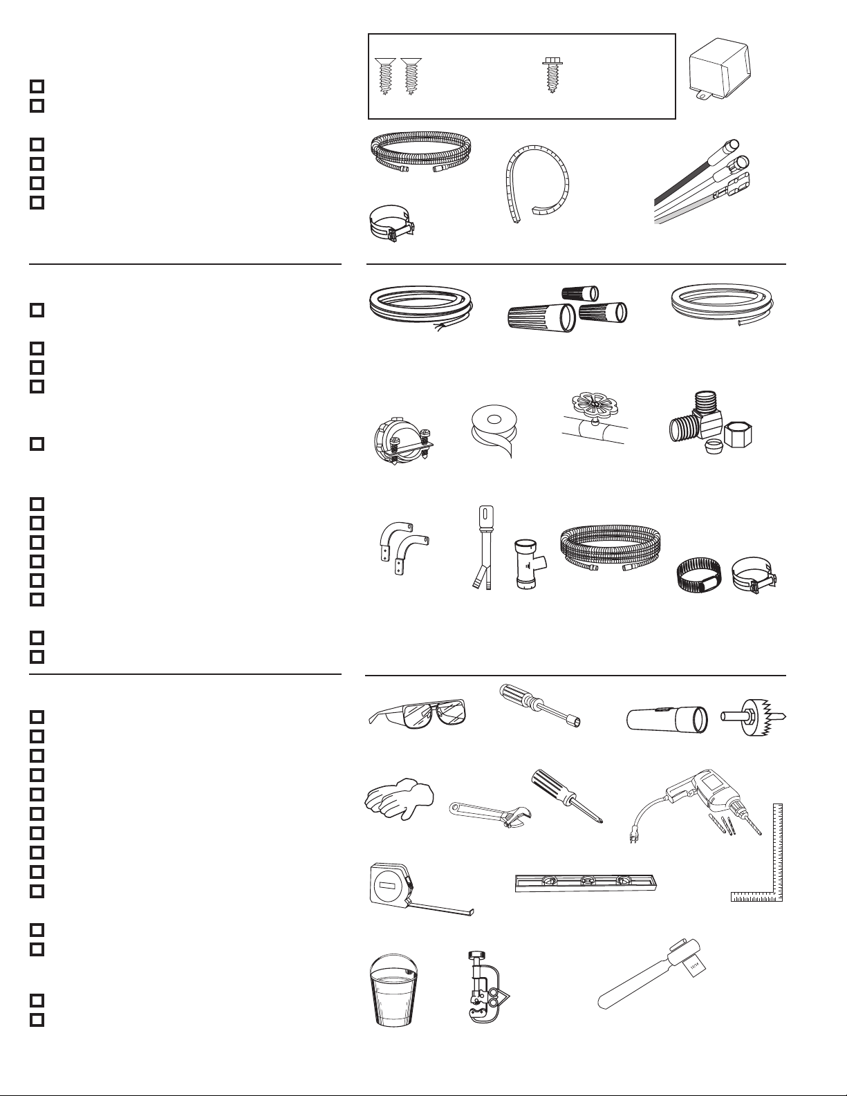
PARTS SUPPLIED IN INSTALLATION
PACKAGE:
■ Two 8-18 x 5/8" Phillips-head wood screws
■ Junction box cover and #10 hex head
screw
■ Drain hose (78" long) and hose clamp
■ Cord protector (Power Cord Models Only)
■ Conversion leads (Power Cord Models Only)
■ Literature, product samples and/or
coupons
MATERIALS YOU WILL NEED:
■ WX09X70910 power cord if applicable to
your installation
■ UL-Listed wire nuts (3)
■ Thread seal tape
■ 90° elbow, ferrule and compression nut –
(3/8" NPT external thread on one end and
opposite end sized to fit water supply)
■ GPF65 Side-mount bracket kit for use with
granite countertops
FOR NEW INSTALLATIONS:
■ Electrical cable
■ Water line–3/8" minimum copper tubing
■ Strain relief for electrical connection
■ Hand shut-off valve (recommended)
■ Air gap for drain hose, if required
■ Waste tee for house plumbing, if
applicable
■ GPF10S drain hose (10' long), if needed
■ Screw-type hose clamps
#8
Phillips-Head
Wood Screws
5/8" long
78" Drain Hose
Hose Clamp
Electrical Cable
or WR09X70910
Power Cord
Strain Relief
GPF65 Side-Mount
Bracket Kit
Screw Kit
Cord Protector
(Power Cord Models Only)
3 Wire Nuts
Thread
Seal Tape
Waste Tee
Air
Gap
#10
Hex Head
Junction Box Screw
1/2" long
Shut-Off
Valve
Optional 10'
Drain Hose
GPF10S
Junction Box Cover
Conversion Leads
(Power Cord Models Only)
Hot Water Line–3/8"
Minimum Copper
Tubing
90° Elbow, Ferrule and
Compression Nut
Screw-Type
Hose Clamps
TOOLS YOU WILL NEED:
■ Safety glasses
■ 1/4" and 5/16" nutdrivers
■ Flashlight
■ Gloves
■ Adjustable wrench (6”)
■ Phillips-head screwdriver
■ Measuring tape
■ Level
■ Carpenter’s square
■ Bucket to catch water when flushing
water line
■ Tubing cutter
■ 15/16" socket wrench
FOR NEW INSTALLATIONS:
■ Hole saw set
■ Drill and appropriate bits
2
Safety Glasses
Gloves
Measuring Tape
Bucket
1/4" and 5/16" Nutdrivers
Adjustable
Wrench
Level
Tubing
Cutter
Flashlight
Phillips-Head
Screwdriver
Hole Saw Set
Drill and
Bits
Carpenter’s
Square
15/16"
Socket Wrench
Page 3

Installation Preparation – Enclosure
2" Minimum
Countertop
Dishwasher
27" Minimum
PREPARE DISHWASHER ENCLOSURE
WARNING
ADVERTENCIA
• The rough cabinet opening must have a minimum
width and depth of 24" and height of 34-1/2" ± 1/4"
from the floor to the underside of the countertop.
• The back wall should be free of pipes or wires.
• Adjacent cabinets should be square and plumb to
ensure a good fit. Refer to Figure A.
• For a corner installation, allow 2" minimum
clearance between the dishwasher and the
adjacent wall.
• Provide at least 27" in front of the dishwasher to
allow the dishwasher door to open fully. Refer to
Figure B.
To reduce the risk of shock, fire, or injury
to persons, the installer must ensure that
the dishwasher is completely enclosed at
the time of installation.
Para reducir el riesgo de choque, incendio
o lesión a personas, el instalador se
debe cerciorar de que la lavadora esté
completamente cerrada en el momento
de la instalación.
• The dishwasher must be installed no more than
10 feet from sink for proper drainage.
• The dishwasher must be fully enclosed on the top,
sides and back.
• The dishwasher must not support any part of the
enclosure.
Clearances:
In a corner installation, provide
at least 2" clearance between
the dishwasher and the adjacent
cabinet, wall or other appliance.
Provide at least 27" of clearance
in front of the dishwasher.
Figure B
Figure A
• Make sure the oor is level inside the opening and
even with the finished floor of the kitchen. This will
facilitate removal of the dishwasher at a later date
for service, if needed.
3
Page 4

32"
Min.
18"
Min.
32"
Min.
18"
Min.
Installation Preparation – Drain
Remove
Drain
Plug
PREPARE DRAIN PLUMBING
Drain Requirements
• Follow local codes and ordinances.
• Drain hose must not exceed 10 feet in length.
• A high drain loop or air gap is required. See below.
Drain Method
The type of drain installation depends on the
following:
• Do local codes or ordinances require an air gap?
• Is waste tee less than 18" above the oor?
If the answer to either question is YES, an air gap
(Method 1) must be used. If both answers are NO,
either an air gap or a high drain loop (Method 2)
may be used.
Special consideration for a dishwasher installed
on a pedestal
lf the dishwasher is installed on an elevated
platform, a high drain loop of at least 32" above the
platform must be provided in addition to the air gap
requirement determined above. This is necessary for
proper drain performance.
METHOD 1 – Air Gap with Waste Tee or Disposer
Figure C
Waste Tee Installation
Disposer Installation
METHOD 2 – High Drain Loop with Waste Tee
or Disposer
Provide a method to attach the drain hose to the
underside of countertop. Attachment will be made in
a later step.
Figure D
Waste Tee Installation
Disposer Installation
Install waste tee or disposer and the air gap
according to the manufacturer’s instructions.
CAUTION
An air gap MUST BE USED if the drain hose is connected to
waste tee or disposer lower than 18" above the floor level.
Failure to provide the proper drain connection height with
an air gap or 32" minimum, high drain loop will result in
improper draining of the dishwasher, which may cause
damage.
PRECAUCIÓN
SE DEBE USAR un espacio de aire si la manguera
de drenaje se conecta a la T de desechos o al triturador
menos de 18" por encima del nivel del piso. No disponer
la altura correcta de la conexión del drenaje con
un espacio de aire o 32" de mínimo, una curva alta
de drenaje resultará en un drenaje incorrecto
de la lavadora, lo que pude causar daños.
4
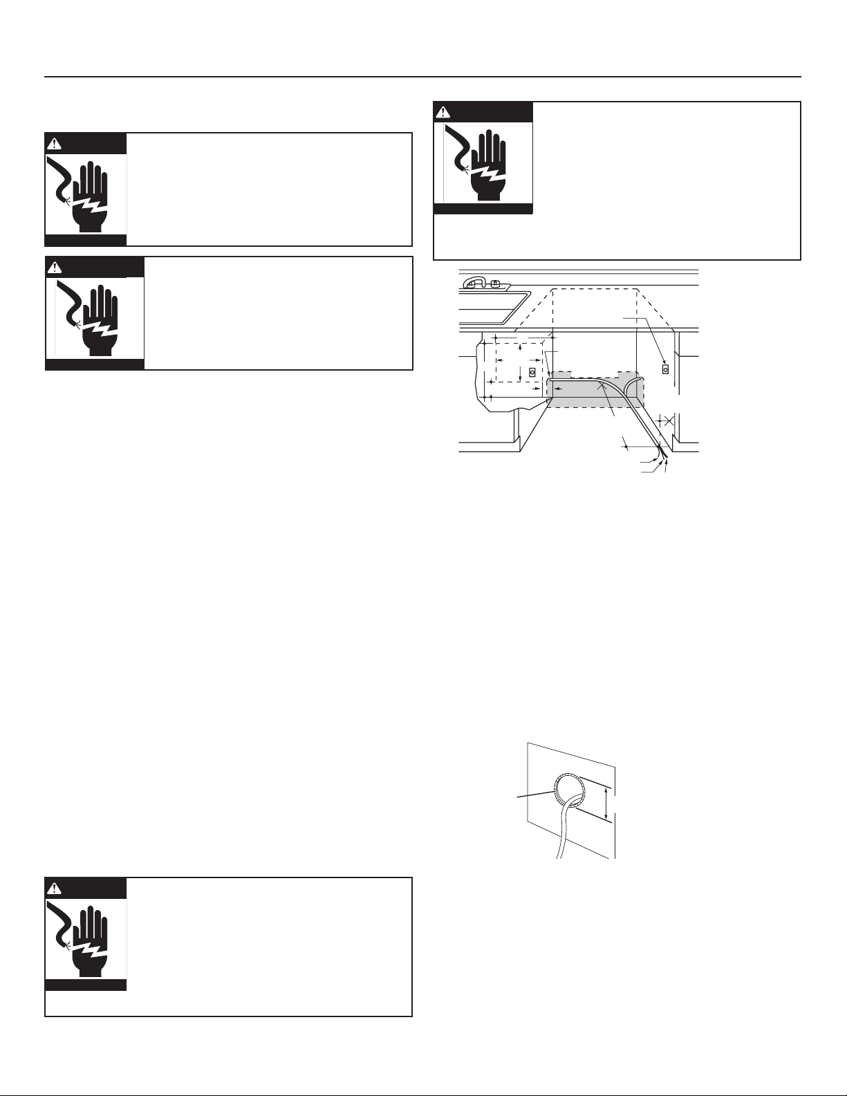
Cabinet Preparation
Drill a 1-1/2" diameter hole in the cabinet wall within
the shaded area shown in Figure A for the drain
hose. Make sure there are no sharp edges. The drain
hose will be passed through this hole and connected
to the drain in a later step.
IMPORTANT – When
connecting the drain line to a
disposer, check to be sure that
drain plug has been removed.
Dishwasher will not drain if
plug is left in place.
Page 5
White
18"
6"
24"
from Wall
3"
from
Cabinet
Alternate
Receptacle
Location
Ground
Black
1-1/2" Dia. Hole ( Max.)
18"
6"
Receptacle
Location
Area
Installation Preparation – Electrical Supply
Hole Diameter
1-1/2" Maximum
Cord
Protector
(Provided
with Power
Cord Models Only)
Metal Cabinet Wall
PREPARE ELECTRICAL WIRING
Electrical Requirements
• This appliance must be supplied with 120V, 60 Hz.,
and connected to an individual properly grounded
branch circuit, protected by a 15- or 20-ampere
circuit breaker or time-delay fuse.
• Wiring must be 2 wire with ground.
• If the electrical supply does not meet the above
requirements, call a licensed electrician before
proceeding.
Grounding Instructions – Permanent Connection
This appliance must be connected to a groundedmetal, permanent wiring system, or an equipmentgrounding conductor must be run with the circuit
conductors and be connected to the equipmentgrounding terminal or lead on the appliance.
Grounding Instructions – Power Cord Models
This appliance must be grounded. In the event of a
malfunction or breakdown, grounding will reduce
the risk of electric shock by providing a path of
least resistance for electric current. This appliance
is equipped with a cord having an equipmentgrounding conductor and a grounding plug. The plug
must be plugged into an appropriate outlet that is
installed and grounded in accordance with all local
codes and ordinances.
WARNING
ADVERTENCIA
WARNING
FOR PERSONAL SAFETY: Remove house fuse
or open circuit breaker before beginning
installation. Do not use an extension cord or
adapter plug with this appliance.
PARA SEGURIDAD PERSONAL: Retire el
fusible de la casa o abra el interruptor de
circuitos antes de empezar la instalación.
No use un cable de extensión o enchufe
adaptador con este aparato.
The improper connection of the equipmentgrounding conductor can result in electric
shock. Check with a qualified electrician or
service representative if you are in doubt that
the appliance is properly grounded.
Do not modify the plug provided with the
appliance; if it will not fit the outlet, have
a proper outlet installed by a qualified
technician.
ADVERTENCIA
Figure E
La conexión incorrecta del conductor
de conexión a tierra del equipo puede
resultar en choque eléctrico. Consulte con
un electricista calificado o representante
de servicio si tiene dudas de la conexión
a tierra del aparato. No modifique el
enchufe que se suministra con el aparato;
si no calza en el tomacorrientes, haga
que un técnico calificado le instale un
tomacorrientes adecuado.
Cabinet Preparation and Wire Routing
• The wiring may enter the opening from either side,
rear or floor within the shaded area illustrated
above in Figure E and defined in Figure A.
• Cut a 1-1/2" maximum diameter hole to insert the
electrical cable. Permanent wiring connections
may pass through the same hole as the drain
hose and hot water line, if convenient. Hole edges
must be smooth and rounded. If the cabinet wall is
metal, the hole edge must be covered with a cord
protector.
NOTE: Power cords with plug must pass through a
separate hole.
Electrical Connection to Dishwasher
Electrical connection is on the right front of
dishwasher.
• For permanent connections, the cable must be
routed as shown in Figure E. The cable must extend
a minimum of 24" from the rear wall.
• For power cord connections, install a 3-prong
grounding-type receptacle in the adjacent cabinet
rear wall, between 6" and 18" from the opening, 6"
to 18" above the floor as shown in Figure E.
5
Page 6

Installation Preparation – Hot Water Supply
6"
5"
5"
4"
Cabinet Face
Shut-off
Valve
4"
2" From Floor
19" From Wall
2"
From
Cabinet
1-1/2" Dia.
Hole
Hot
PREPARE HOT WATER SUPPLY
Hot Water Line
• The line may enter from either side, rear or floor
within the shaded area shown in Figure F.
• The line may pass through the same hole as the
electrical cable and drain hose, or cut an additional
1-1/2" diameter hole to accommodate the water
line. If a power cord with plug is used, the water line
must not pass through the power cord hole.
CAUTION
The hot water supply line pressure must be at least 20 PSI.
Lower pressures could cause the water valve to leak and
cause water damage.
PRECAUCIÓN
La línea de presión del suministro de agua caliente debe
ser al menos 20 PSI. Presiones inferiores podrían causar
que la válvula del agua gotee y causar daños por agua.
Figure F
Water Line Connection
• Turn off the water supply.
• Install a hand shut-off valve in an accessible
location, such as under the sink. (Optional, but
strongly recommended and may be required by
local codes.)
• The water connection is on the left side of the
dishwasher. Install the hot water inlet line, using
3/8" or larger copper tubing. Route the line as
shown in Figure F and extend forward at least 19"
from rear wall.
• Adjust the water heater to deliver water between
120°F and 150°F.
• Flush water line to clean out debris. Use a bucket
to catch water and debris.
• The hot water supply line pressure must be
between 20 and 120 PSI.
6
Page 7

Dishwasher Installation
Insert Hook Through
Hole from Inside of Frame
Link fully seated
in hinge arm
CAUTION
Do not remove the wood base until you are ready to
install the dishwasher. The dishwasher will tip over
when the door is opened if the base is removed.
PRECAUCIÓN
No retire la base de madera hasta que esté listo para
instalar la lavadora de platos. Cuando la puerta se abra,
la lavadora de platos se inclinará si la base se retira.
STEP 1: PREPARATION
Locate the items in the installation package and set
them aside for use in the listed steps.
• Screw kit – Steps 5 or 16 and 13
• Junction box cover – Steps 5 or 16
• Drain hose and drain hose clamp – Step 7
• Owners’ Manual – Steps 18 and 21
• Product Samples and/or coupons – Step 21
• Conversion leads (Factory-equipped power cord
models only) – Appendix
STEP 2: CHECK DOOR BALANCE
• With the dishwasher on the wood base, check the
door balance by opening and closing the door.
• The door is properly balanced if it gently drops
from a 1/2 open position and does not rise from
the full open position.
• If necessary, increase or decrease tension as
shown. Latch the door and adjust springs to
correct balance.
Figure G
Tip: Avoid service calls for door balance problems.
Make sure the spring end is fully engaged in a
frame hole and the spring link is fully seated in the
hinge arm.
STEP 3: REMOVE WOOD BASE
IMPORTANT – Do not kick off wood base!
Damage will occur.
• Move the dishwasher close to the installation
location and lay it on its back.
• Remove the four leveling
legs from the underside of
the wood base
with a 15/16"
socket wrench.
• Remove and
discard wood
base.
Figure H
• Screw leveling legs back into the dishwasher
frame, approximately 3/4" from the frame, as
shown.
STEP 4: REMOVE ACCESS PANEL
AND TOEKICK
The top mounting holes in the access panel are
slotted.
• Remove the lower two 10-16 x 3/8" sheet metal
screws. Do not remove the two top 8-32 x 1/4"
machine thread screws.
• Slide the access panel to the left as far as it will go.
• Gently pull the access panel forward to remove
it from the top screws.
Set access panel, toekick and screws aside for use
in Step 20.
Tip: Prevent
tub damage.
Remove only
the 3/8" sheet
metal screws
in this step.
This will help
prevent a mix-
up with the
1/4" machine
thread screws
in Step 20.
Figure I
7
Page 8

Dishwasher Installation
90° Elbow
Fill Hose
Water Valve
Bracket
Thread Seal
Tape
STEP 5: INSTALL POWER CORD
Skip this step if the dishwasher will be
permanently connected to the house electrical
system or has a factory-installed power cord.
In this step you will need the junction box cover and
the #10 x 1/2" hex-head screw from the screw kit set
aside in Step 1.
The power cord and connections must comply
with the National Electrical Code, Section 422 and/
or local codes and ordinances. Maximum power
cord length is 6 feet. Power Cord Kit WX09X70910,
available for purchase from an authorized GE
appliance dealer, meets these requirements.
STEP 6: INSTALL 90° ELBOW
• Wrap a 90° elbow with thread seal tape.
• Thead the 90° elbow into the water valve.
• Do not overtighten the elbow; water valve bracket
could bend or the valve fitting could break.
• Position the end of the elbow to face the rear
of the dishwasher.
Figure K
STEP 7:
INSTALL DRAIN HOSE TO
DISHWASHER DRAIN PORT
Skip this step if drain hose has been preinstalled.
In this step you will need the drain hose and clamp
set aside in Step 1.
Figure J
• Install strain relief in the junction box bracket.
• Insert the power cord through the strain relief and
tighten.
• Make sure black, white and green dishwasher
wires are threaded through the small hole in the
junction box bracket.
• Connect power cord white (or ribbed) to
dishwasher white, black (or smooth) to dishwasher
black and ground to dishwasher green wire. Use
UL-listed wire nuts of appropriate size.
• Install junction box cover using the #10 hex-head
screw. Be sure wires are not pinched under the
cover.
8
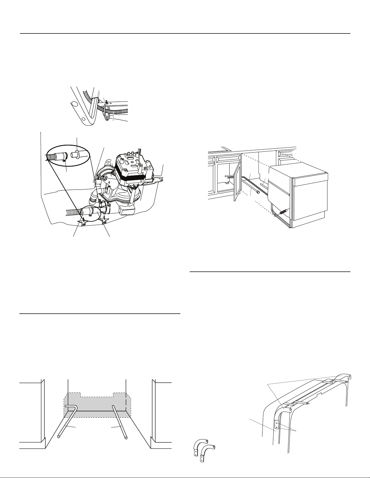
IMPORTANT – Prevent drain hose damage
and possible leaks. Be careful not to nick or cut
the drain hose.
• Route the small end of the drain hose from the left
side of the dishwasher through the strain relief
attached to the dishwasher frame and toward
the center of the dishwasher as shown in Figures
L and M.
• Place the hose clamp over the small end of the
drain hose.
• Push the small end of the drain hose over the drain
port on the collection chamber, making sure it is
fully seated against the hose stop.
• Tighten the hose clamp to at least 15 inch-pounds
of torque.
Page 9
Bracket
Attachment
Screws
(2 Each
Side)
Side-
Mounting
Brackets
Tub Frame
Water
Line
Power
Supply
Water
Power
Drain
Dishwasher Installation
Drain Hose
Do not use
this port if
present
Collection Chamber
Drain Port
Hose Clamp
Hose Stop
Strain
Relief
Drain Hose
Note: The drain hose supplied with the dishwasher
is approximately 78" long. If a longer hose is needed,
a 10-foot-long hose may be purchased from an
authorized GE appliance dealer. The 10-foot-long
hose is part number GPF10S.
Figure L
STEP 9: INSERT DRAIN HOSE AND POWER
CORD, IF USED, THROUGH CABINET
• Upright the dishwasher and position it in front of
the cabinet opening.
• Insert the drain hose into the hole previously drilled
in the cabinet wall.
• If a power cord is used, guide the end of the cord
through a separate hole cut for the power cord.
The power cord should be routed directly to the rear
of the junction box, avoiding contact with the door
spring and other dishwasher components.
Figure O
Figure M
Tip: Avoid unnecessary service charges for drain
issues.
Make sure the drain hose connection is leak-free
and the hose is routed through the strain relief so
it will not kink when the dishwasher is installed into
the cabinet.
STEP 8: POSITION WATER LINE AND
POWER SUPPLY
• Position the water supply line and house wiring on
the floor of the opening to avoid interference with
the base of the dishwasher and components under
the dishwasher.
Tip: Avoid unnecessary service charges for no fill,
drain or noise concerns.
Position utility lines so they do not interfere with
anything under or behind the dishwasher.
STEP 10: INSTALL OPTIONAL GPF65 SIDE
MOUNT BRACKETS
Skip this step if the underside of countertop is
wood or woodlike material.
• Purchase and install the GPF65 side-mount
bracket kit if the underside of counter is granite
or a similar material that will not accept wood
screws. The GPF65 kit is available from authorized
GE appliance dealers.
• Refer to Figure P and follow the instructions
included in
the kit.
Figure N
Optional
Side-Mount
Bracket Kit
Figure P
9
Page 10
Dishwasher Installation
Turn Legs
to Adjust
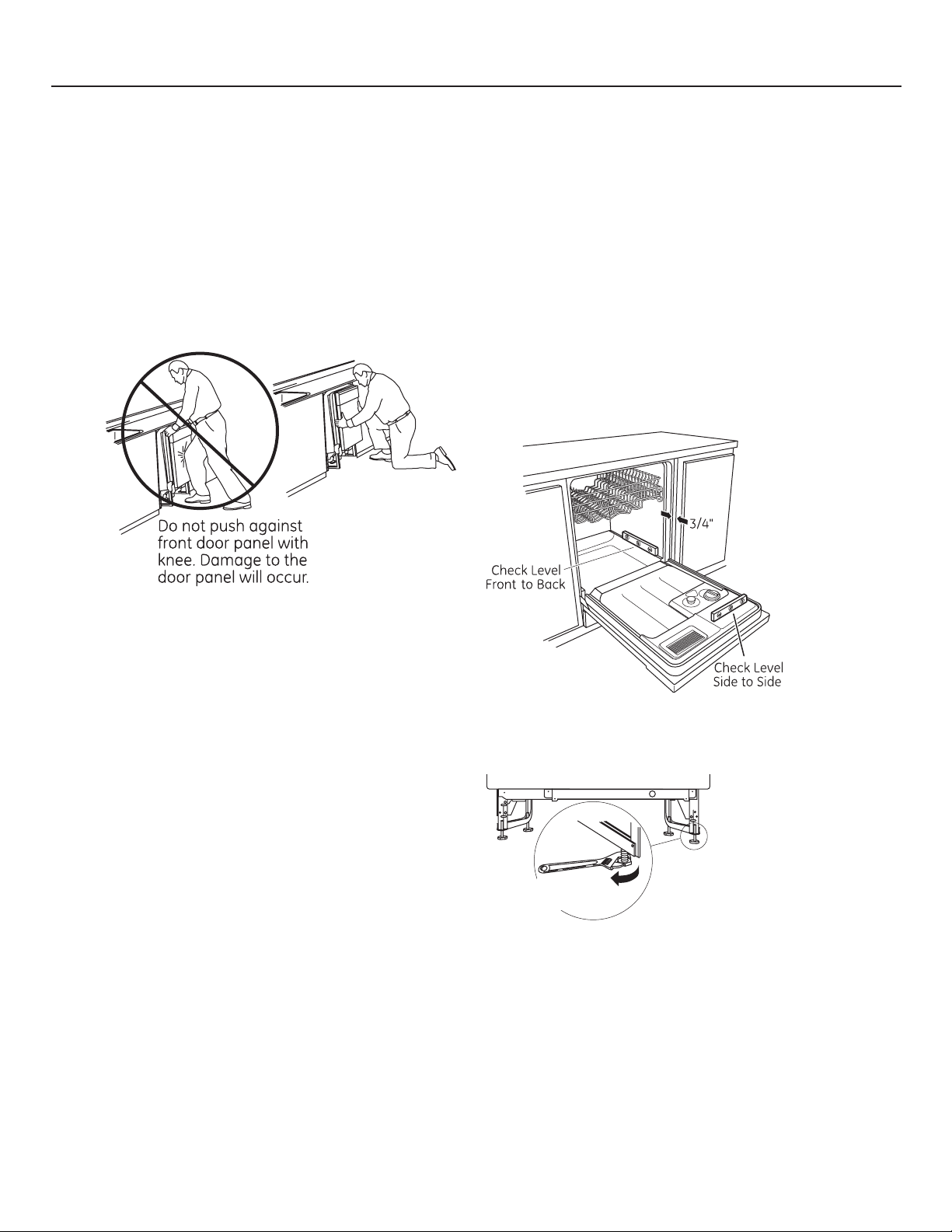
STEP 11: SLIDE DISHWASHER INTO CABINET
IMPORTANT – Do not push against the front
panel with knees. Damage will occur.
• Grasp the sides of the front panel and slide the
dishwasher into the opening a few inches at
a time. Pull the drain hose and power cord, if
equipped, through the holes in the adjacent
cabinet while sliding the dishwasher into position.
Figure Q
STEP 12: POSITION AND LEVEL
DISHWASHER
IMPORTANT – Dishwasher must be level for
proper dish rack operation, wash performance
and door operation. The dishwasher must be
leveled left to right and front to back. This ensures
that the dish racks will not roll in or out on their
own, circulation water will flow to the pump inlet,
and the door will close without hitting the side of
the tub.
• Remove the lower dish rack and place a level on
the door and lower rack track as shown in Figure R.
• Check the tub insulation blanket, if equipped, to
be sure it is smoothly wrapped around the tub.
It should not be “bunched up” and it must not
interfere with the door springs. If the insulation
is “bunched up” or interfering with the springs,
straighten and re-center the blanket prior to sliding
the dishwasher into its final position.
• Make sure the drain hose is not kinked under or
behind the dishwasher.
• Make certain the house wiring, drain line and
water line do not interfere with components under
the dishwasher.
• The dishwasher tub ange should be
approximately 3/4" behind the face of the adjacent
cabinet. Refer to Figure R.
Tip: Avoid unnecessary service charges for panel
damage.
Do not press on the center of panel with hands or
knees when sliding dishwasher into position.
10
Figure R
• Adjust the level of the dishwasher by individually
turning the four legs on the bottom of the
dishwasher as illustrated in Figure S.
Figure S
• The dishwasher is properly leveled when the level
indicator is centered left to right and front to back.
The dishwasher door should close without hitting
the sides of the tub.
• Replace the lower rack.
Tip: Avoid unnecessary service charges for poor
wash performance and rack operation.
Pull the dish racks half way out. They should remain
stationary. Open and close the door. The door should
fit in the tub opening without hitting the side of the
tub. If the racks roll on their own, or the door hits the
side of the tub, relevel the dishwasher.
Page 11

Dishwasher Installation
90° Elbow
Hot Water
Supply Line
Fill Hose
Water Valve Bracket
Ferrule
Hot Water
Supply Line
Compression Nut
90°
Elbow
STEP 13: FASTEN DISHWASHER TO
UNDERSIDE OF COUNTERTOP OR SIDES
OF CABINET
In this step you will need the two 5/8" Phillips-head
wood screws set aside in Step 1.
IMPORTANT – Dishwasher must be centered
in cabinet opening. Interference with cabinets or
countertop will cause leaks and damage to the
door panel and/or control panel.
• If countertop is wood or woodlike material, fasten
the dishwasher to the countertop by driving the
Phillips head screws through the countertop
brackets and into the countertop.
• If the countertop is granite or similar material,
drive Phillips screws through side mount brackets
and into the adjacent cabinets.
• Make sure screws are driven straight and ush
to prevent interference with door operation and
damage to the control panel. See Figure T.
STEP 14: CONNECT WATER SUPPLY
Connect the water supply line to the 90° elbow
installed in Step 6.
• Slide the compression nut and then the ferrule over
the end of the water line.
• Insert the water line into the 90° elbow.
• Slide the ferrule against the elbow and secure
with the compression nut.
Figure T
Tip: Avoid unnecessary service charges for leaks
or control panel damage.
Make sure the dishwasher is centered in the cabinet
and the door opens and closes freely without hitting
the adjacent cabinets. Drive mounting screws
straight and flush.
Figure U
IMPORTANT – Check to be sure the door
spring does not rub or contact the fill hose or
water supply line. Test by opening and closing the
door. Reroute the water supply lines or slightly
bend the water valve bracket if a rubbing noise or
interference occurs.
Tip: Avoid unnecessary service charges for noise
or leaks.
Make sure the door spring does not rub against the
fill hose or water supply line.
11
Page 12

Dishwasher Installation
Remove
Drain
Plug
STEP 15: CONNECT DRAIN LINE
The molded end of the drain hose will fit 5/8"
through 1" diameter inlet ports on the air gap, waste
tee or disposer.
• Determine the size of the inlet port
• Cut the drain hose connector on the marked line, if
required, to fit the inlet port.
Figure V
• If a longer drain hose is required, and you did not
purchase the GPF10S drain hose, add up to 42"
length, for a total of 120" (10 feet), to the factoryinstalled hose. Use 5/8" or 7/8" inside diameter
hose and a coupler to connect
the two hose ends.
Secure the
connection
with hose
clamps.
Figure W
IMPORTANT – Total drain hose length must
not exceed 10 feet for proper drain operation.
Method 1 – Air gap with waste tee or disposer
Waste Tee Installation
Figure X
Disposer Installation
Method 2 – “High drain loop” with waste tee
or disposer
Fasten the drain hose to the underside of the
countertop with a hanger.
Waste Tee Installation
Figure Y
Disposer Installation
IMPORTANT – When connecting the drain
line to a disposer, check to be sure that the drain
plug has been removed. Dishwasher will not drain
if plug is left in place.
• Connect drain line to air gap, waste tee, or disposer
using the previously determined method. Secure
the hose with a screw-type clamp.
12
Tip: Avoid unnecessary service call charges
for a “no drain” complaint.
Make sure any excess drain hose has been pulled
through the cabinet opening. This will prevent
excess hose in the dishwasher cavity from
becoming kinked or crushed by the dishwasher.
Make sure the disposer plug has been removed if
the drain hose is connected to a disposer.
Page 13

Dishwasher Installation
STEP 16: CONNECT POWER SUPPLY
If a power cord with plug is already installed,
proceed to Step 17.
If the dishwasher came with a factory-installed
power cord and you want to convert it to a
permanent connection, refer to the instructions on
page 16.
WARNING
If house wiring is not 2-wire with a ground
wire, a ground must be provided by the
installer.
When house wiring is aluminum, be sure
to use U.L. listed anti-oxidant compound
and aluminum-to-copper connectors.
ADVERTENCIA
• Secure house wiring to the back of the junction
box bracket with a strain relief.
• Locate the three dishwasher wires (white, black
and green) with stripped ends. Insert dishwasher
wires through the small hole in the junction box
bracket. Use UL-listed wire nuts of appropriate size
to connect incoming ground to green, white
to white and black to black.
Figure Z
Si el cableado de la casa no es de 2 cables
con un cable de conexión a tierra, el
instalador debe suministrar una conexión
a tierra.
Cuando el cableado de la casa es en
aluminio, cerciórese de usar un compuesto
anti-oxidante aprobado por U.L. y un
compuesto de aluminio a cobre.
STEP 17: INSTALL JUNCTION BOX COVER
If junction box cover is already installed, skip to
Step 18.
In this step you will need the junction box cover and
the #10 hex-head screw from the screw kit set aside
in Step 1.
• Install the junction box cover using the #10 hex-
head screw. Check to be sure that wires are not
pinched under the cover.
STEP 18: PRETEST CHECKLIST
■ Verify that power is turned off at the source.
■ Open the dishwasher door and remove all foam
and cardboard packaging.
■ Read the Owner’s Manual to familiarize yourself
with the operation of the dishwasher.
■ Check to be sure that the wiring is secure under
the dishwasher and not pinched or in contact
with door springs or other dishwasher
components.
■ Check that the door spring does not contact the
water line, fill hose, or adjacent cabinets. See
Steps 13 and 14.
■ Pull lower rack about halfway out. Check to be
sure it does not roll back into dishwasher or
further out. If it does, relevel the dishwasher.
See Step 12.
■ Check to be sure control panel does not touch
adjacent cabinets. If it does, reposition the
dishwasher. See Step 13.
■ Turn on the hot water faucet at the sink to verify
that the water temperature is at least 120°F
and not more than 150°F. Adjust water heater
if necessary.
■ Add two quarts of water to the bottom of the
dishwasher to lubricate the pump seal.
■ Turn on water supply.
■ Check for water leaks. Tighten connections
if necessary. See Step 14.
■ Remove the protective film, if present, from
the control panel, access panel and door panel.
13
Page 14

Dishwasher Installation
Flood Float
Cover
Hi- T emp
W ash
Heavy
W ash
P ots
& P ans
Cycles
Normal
W ash
Hot
S ta r t
Hea t ed
D r y
Hot Start
Option
S ta r t Delay
(HRS)
Cycle
on
Off
1
3
2
4
6
5
Pla t e W armer
(Heated D r y On)
Rinse Only
(Heated D r y Of f )
S ta r t
Light W ash
R eset
H
EAVY
W
ASH
P
OTS
&
P
ANS
Cycles
N
ORMAL
W
ASH
C
HINA
C
RYSTAL
R
INSE
O
NLY
S
TART
R
ESET
C
LEAN
C
LEAN
HI T
EMP
R
INSE
HI T
EMP
W
ASH
H
EATED
D
RY
D
ELAY
H
OURS
L
OCK
(2 T
IMES
)
248
Red Connector
STEP 19: DISHWASHER WET TEST
CHECKLIST
■ Turn on power supply or if power cord is used,
plug it into the wall outlet.
■ Latch dishwasher door.
■ For electronic dishwashers, select the NORMAL
WASH cycle and press the START pad one time.
■ For dial models, press the NORMAL and HOT
START pads, if model has them, and then turn the
control dial just enough to start the dishwasher.
Be careful not to turn the dial past the first water
fill. Dial should point to “Hot Start Option” or “Hot
Prewash Option” depending on model.
– Check the electrical connection to the water
valve. The red electrical connector should be
plugged into the dishwasher water valve. If it
is not plugged in, turn off electrical power to
the dishwasher. Plug the red connector into the
dish washer water valve and then restore power.
Appearance varies by model. Not all models have push buttons.
■ Check to be sure that water enters the
dishwasher. This could take up to 4 minutes.
If water does not enter the dishwasher:
– Check to be sure that the water is turned on.
– Lightly tap the flood float cover to dislodge
a stuck flood float.
■ Check for leaks under the dishwasher. If a leak is
found, turn off power, tighten connections and
restore power.
■ Check for leaks around the door. A leak around
the door could be caused by the dishwasher door
rubbing or hitting adjacent cabinets. Reposition
the dishwasher if necessary. See Steps 11, 12
and 13.
■ Most dishwasher models will drain about
3 minutes after the first fill. Check the drain line
for leaks when dishwasher drains. If leaks are
found, turn off power, correct as necessary
and then restore power.
■ Open the dishwasher door and make sure most
of the water has drained. If the water does not
drain, check to be sure disposer plug has been
removed and/or air gap is free of debris.
■ Let the dishwasher run through another fill and
drain cycle. Check again to be sure there are no
leaks.
■ At the end of the second drain, push the reset pad
on electronic models. For dial models, unlatch the
door and rotate the dial to the “Off” position.
14
Page 15

Dishwasher Installation
STEP 20: REPLACE ACCESS PANEL AND
TOEKICK
In this step you will need the panels and the two
screws set aside in Step 4.
There are two types of screws used. The 8-32 x 1/4"
screws are used at the top of the access panel and
should still be in place. The 10-16 x 3/8" screws are
used at the bottom of the access panel and secure
both the access panel and toekick.
IMPORTANT – Screws are not
interchangeable. To prevent damage to your
dishwasher, use the proper screw in the proper
location. Do not mix screw types or lengths.
• Place the toekick against the legs of the
dishwasher.
• Remove the two 8-32 x 1/4" machine-thread
screws.
• Align the access panel to the dishwasher.
• Select the two 8-32 x 1/4" machine-thread screws
just removed and insert them through the top
holes in the access panel and into the dishwasher
frame.
• Tighten these screws.
• Align the toekick and make sure the bottom edge
is against the floor.
• Insert and tighten the two 10-16 x 3/8" sheet metal
thread screws, making sure the bottom edge of
the toekick stays in contact with the floor.
STEP 21: LITERATURE
■ Leave the Owners’ Manual, Installation
Instructions, samples and/or coupons with
consumer.
Figure AA
Tip: Prevent tub damage and reduce sound from
under the dishwasher.
Use the machine-thread screws in the top holes and
the sheet metal-thread screws in the bottom holes.
Make sure the toekick is against the floor.
15
Page 16

Appendix
Conversion Harness
CONVERTING DISHWASHER WITH FACTORYEQUIPPED POWER CORD TO A PERMANENT
CONNECTION
This procedure requires the conversion leads set
aside in Step 1.
• Make sure the power cord for the dishwasher is
unplugged from the wall outlet.
• Remove screw from junction box cover and
remove cover if present.
• Disconnect the three power cord conductors from
the dishwasher harness. See Figure BB.
• Remove and discard the power cord.
• Connect the conversion harness (included with
dishwasher) to the dishwasher harness by
connecting like-colored wires. See Figure CC.
• Return to Step 16 in these instructions to complete
the conversion.
Figure BB
SPECIFICATIONS SUBJECT TO CHANGE WITHOUT NOTICE
GE Consumer & Industrial
General Electric Company
Louisville, Kentucky 40225
GEAppliances.com
Figure CC
206C1559P195 31-30255
07-09 JR
16
Page 17

GSD2000
Appareils ménagers GE
Consumer and Industrial
Instructions d’installation
Lave-vaisselle encastré
Pour toute question, composez le 1.800.561.3344 ou visitez notre site Web :
www.electromenagersge.ca
ARRÊT
AVANT DE COMMENCER
Veuillez lire attentivement toutes les
directives qui suivent.
IMPORTANT – Observez tous les codes
et ordonnances en vigueur.
• Note à l’installateur – Veuillez laisser les présentes
directives au consommateur pour l’inspecteur local.
• Note au consommateur – Veuillez conserver les
présentes directives avec votre Manuel d’utilisation
pour consultation ultérieure.
• Compétences requises – L’installation de ce
lave-vaisselle exige des compétences de base
en mécanique, en électricité et en plomberie.
L’installateur est responsable de la qualité
de l’installation. Toute défaillance du produit
attribuable à une installation inadéquate n’est
pas couverte par la garantie de GE. Reportezvous à la garantie du produit.
• Durée de l’installation – Entre 1 et 3 heures.
L’installation d’un nouveau lave-vaisselle exige
plus de temps que le remplacement d’un ancien
modèle.
IMPORTANT – Le lave-vaisselle DOIT être
installé de manière à ce qu’il puisse être sorti
de son emplacement si des réparations sont
nécessaires.
Si le lave-vaisselle que vous avez reçu est
endommagé, communiquez immédiatement avec
votre détaillant ou l’entrepreneur en construction.
Accessoires facultatifs – Reportez-vous au Manuel
d’utilisation pour connaître les ensembles pour
panneau décoratif personnalisé offerts.
POUR VOTRE SÉCURITÉ
Veuillez lire et observer toutes les mises en garde
(ATTENTION et AVERTISSEMENT) données dans les
présentes directives. Pour effectuer l’installation
décrite dans les présentes directives, il faut porter
des gants et des lunettes de sécurité.
VEUILLEZ LIRE ATTENTIVEMENT ET
CONSERVER CES DIRECTIVES.
206C1559P195 31-30255 07-09 JR
Page 18

PIÈCES FOURNIES :
■ Deux vis à bois Phillips n° 8-18 x 15,8 mm
(5/8 po)
■ Couvercle de la boîte de jonction et vis à tête
hexagonale n° 10
■ Boyau de vidange (198 cm [78 po] de long)
et collier
■ Protège-cordon d’alimentation (modèles dotés
d’un cordon d’alimentation seulement)
■ Fils pour la conversion (modèles dotés d’un
cordon d’alimentation seulement)
■ Documentation, échantillons et(ou) bons
MATÉRIEL NÉCESSAIRE :
■ Cordon d’alimentation WX09X70910,
si nécessaire pour votre installation
■ Connecteurs vissables homologués UL (3)
■ Ruban pour joints filetés
■ Coude de 90°, bague et écrou à compression
(filetage externe NPT de 9,5 mm [3/8 po]
à une extrémité et l'autre extrémité conçue
pour le raccordement à la conduite
d'alimentation en eau)
■ Ensemble de supports de montage latéraux
GPF65 si le comptoir est en granite
POUR UNE NOUVELLE INSTALLATION :
■ Câble électrique
■ Conduite d'alimentation en eau–tuyau
en cuivre d'au moins 9,5 mm (3/8 po)
■ Bague anti-traction pour le raccordement
électrique
■ Robinet d'arrêt (recommandé)
■ Coupure anti-refoulement pour le boyau
de vidange, si nécessaire
■ Raccord en T pour la plomberie de la résidence,
s'il y a lieu
■ Boyau de vidange GPF10S (3 m / 10 pi de long),
si nécessaire
■ Colliers à vis sans fin
OUTILS NÉCESSAIRES :
■ Lunettes de sécurité
■ Tourne-écrous de 6,3 mm (1/4 po) et de 7,9 mm
(5/16 po)
■ Lampe de poche
■ Gants
■ Clé à molette (15,2 cm [6 po])
■ Tournevis Phillips
■ Ruban à mesurer
■ Niveau
■ Équerre de charpentier
■ Seau pour recueillir l’eau lors du rinçage
de la conduite d’eau
■ Coupe-tubes
■ Clé à douille de 23,8 mm (15/16 po)
Ensemble de Vis
Vis à bois Phillips
n° 8 de 15,8 mm
(5/8 po) de long
Boyau de vidange
de 198 cm (78 po)
Collier
Câble électrique ou
cordon d'alimentation
WR09X70910
Bague
anti-traction
Ensemble
de supports
de montage
latéraux GPF65
Lunettes de sécurité
Gants
Ruban à mesurer
Coupure
anti-refoulement
Clé à molette
Vis à tête hexagonale n° 10
de 12,7 mm (1/2 po) de long
pour boîte de jonction
Protège-cordon
d'alimentation
(modèles dotés d'un
cordon d’alimentation
seulement)
3 connecteurs vissables
Ruban pour
joints filetés
Boyau de vidange
facultatif GPF10S
de 3 m (10 pi)
Tourne-écrous
de 6,3 mm (1/4 po)
et de 7,9 mm (5/16 po)
Niveau
Robinet
d'arrêt
Tournevis
Phillips
Fils pour la
conversion (modèles
dotés d’un cordon
d’alimentation
seulement)
Conduite d'eau chaude–
tuyau en cuivre d'au
moins 9,5 mm (3/8 po)
Coude de 90°, bague
et écrou à compression
Colliers à vis sans fin
Raccord en T
Lampe de poche
Perceuse
et forets
Couvercle
de la boîte
de jonction
Jeu de
scies-cloche
Équerre de
charpentier
POUR UNE NOUVELLE INSTALLATION :
■ Jeu de scies-clochet
■ Perceuse et forets appropriés
2
Seau
Coupe-tubes
Clé à douille de 23,8 mm
(15/16 po)
Page 19

Préparation pour l'installation – Ouverture dans les armoires
2" Minimum
Countertop
Dishwasher
27" Minimum
PRÉPARATION DE L'OUVERTURE DANS
LES ARMOIRES
AVERTISSEMENT
• L'ouverture dans les armoires doit mesurer au
moins 61,0 cm (24 po) de largeur et de profondeur,
et 87,6 cm ± 6,3 mm (34 1/2 po ± 1/4 po) de
hauteur à partir du plancher jusqu'au-dessous
du comptoir.
• Le mur du fond doit être exempt de tuyaux
ou de fils.
• Les armoires adjacentes doivent être à l'équerre
et d'aplomb pour une installation appropriée.
Reportez-vous à la Figure A.
• Dans le cas d'une installation dans un coin,
prévoyez un jeu d'au moins 5,1 cm (2 po) entre
le lave-vaisselle et le mur adjacent.
• Prévoyez au moins 69 cm (27 po) à l'avant
du lave-vaisselle pour ouvrir la porte
complètement. Reportez-vous à la Figure B.
Pour réduire les risques de choc
électrique, d'incendie ou de blessures,
l'installateur doit s'assurer que le lavevaisselle est complètement encastré
au moment de l'installation.
• Le lave-vaisselle doit être installé au maximum
à 3 mètres (10 pieds) de l’évier pour assurer une
vidange adéquate.
• Le dessus, les côtés et l’arrière du lave-vaisselle
doivent être complètement dissimulés à l’intérieur
de l’ouverture.
• Le lave-vaisselle ne doit soutenir aucune partie
de la structure des armoires.
Dégagements :
Comptoir
Lave-vaisselle
69 cm (27 po)
minimum
5,1 cm (2 po) minimum
Figure B
Dans le cas d’une installation
dans un coin, veuillez prévoir
un dégagement d’au moins
5,1 cm (2 po) entre le lavevaisselle et les armoires,
le mur ou un électroménager
adjacent.
Veuillez prévoir un
dégagement d’au moins
69 cm (27 po) à l’avant
du lave-vaisselle.
Le mur du fond
doit être exempt
87,6 cm ± 6,3 mm
(34 1/2 po ± 1/4 po)
du dessous
du comptoir
au plancher
Figure A
de tuyaux ou de fils
12,5 cm
10,1 cm
(5 po)
(4 po)
Le plancher DOIT
être au même niveau
que le plancher
de la pièce
12,5 cm
61,0 cm
(5 po)
(24 po)
min.
10,1 cm
(4 po)
Armoires
15,2 cm
(6 po)
La partie ombrée est réservée
à la plomberie et à l'électricité
à l'équerre
et d'aplomb
• Assurez-vous que le plancher est de niveau
à l'intérieur de l’ouverture et au même niveau
que le plancher fini de la cuisine afin de faciliter le
retrait du lave-vaisselle si jamais il faut le réparer
dans le futur.
3
Page 20

32"
Min.
18"
Min.
32"
Min.
18"
Min.
Préparation pour l’installation – Vidange
Remove
Drain
Plug
PRÉPARATION DE LA PLOMBERIE POUR
LA VIDANGE
Exigences relatives au système de vidange
• Veuillez observer les ordonnances et les codes
locaux en vigueur.
• Le boyau de vidange doit avoir une longueur
maximale de 3 mètres (10 pieds).
• Il faut prévoir une boucle de vidange élevée
ou l’installation d’une coupure anti-refoulement.
Voir ci-dessous.
Méthode de vidange
Le type d’installation de vidange dépend des
conditions suivantes :
• Les ordonnances ou codes locaux en vigueur
exigent-ils une coupure anti-refoulement?
• Le raccord en T se trouve-t-il à moins de 46 cm
(18 po) du plancher?
Si vous répondez OUI à l’une ou l’autre de ces
questions, vous devez installer une coupure antirefoulement (méthode n° 1). Si vous répondez
NON aux deux questions, vous pouvez installer
une coupure anti-refoulement ou aménager
une boucle de vidange élevée (méthode n° 2).
Considérations spéciales dans le cas d’un
lave-vaisselle installé sur une plateforme
Si le lave-vaisselle est installé sur une plateforme,
il faut aménager une boucle de vidange à une
hauteur d’au moins 82 cm (32 po) au-dessus de
la plateforme, en plus d’installer la coupure antirefoulement indiquée ci-dessus, afin d’assurer une
vidange adéquate.
ATTENTION
Il FAUT installer une coupure anti-refoulement si le boyau
de vidange est relié à un raccord en T ou à un broyeur
à déchets situé à moins de 46 cm (18 po) du plancher.
Si le boyau de vidange avec la coupure anti-refoulement
ne se trouve pas à une hauteur minimale de 82 cm (32 po)
au-dessus du plancher, la boucle de vidange élevée
ne pourra pas assurer une vidange appropriée du
lave-vaisselle, ce qui pourrait causer des dommages
à l'appareil.
MÉTHODE N° 1 – Coupure anti-refoulement avec
raccord en T ou broyeur à déchets
Figure C
Installation avec raccord en T
Installation avec broyeur à déchets
MÉTHODE N° 2 – Boucle de vidange élevée avec
raccord en T ou broyeur à déchets
Prévoyez une façon de fixer le boyau de vidange
au-dessous du comptoir. La fixation du boyau de
vidange sera effectuée à une étape ultérieure.
46 cm
(18 po)
min.
81 cm
(32 po)
min.
81 cm
(32 po)
46 cm
min.
(18 po)
min.
Installation avec raccord en T
Figure D
Installation avec broyeur à déchets
Installez le raccord en T ou le broyeur à déchets
et la coupure anti-refoulement en conformité avec
les directives du fabricant.
Préparation des armoires
Percez un trou de 3,8 cm (1 1/2 po) de diamètre
dans la paroi de l’armoire qui se trouve dans
la partie ombrée de la Figure A pour le boyau
de vidange. Assurez-vous que l’orifice ne présente
pas d’arêtes vives. Le boyau de vidange sera inséré
dans ce trou et raccordé au renvoi au cours d’une
étape ultérieure.
IMPORTANT – Lorsque vous
branchez le boyau de vidange
à un broyeur à déchets, assurez-
Enlevez le
bouchon
de vidange
vous d’enlever le bouchon
de vidange. Le lave-vaisselle
ne pourra pas se vider si vous
laissez le bouchon en place.
4
Page 21

7,6 cm (3 po)
des armoires
Autre emplacement
possible pour la prise
de courant
Mise à la terre
18"
Zone pour
la prise
de courant
46 cm
(18 po)
46 cm
(18 po)
15 cm
(6 po)
15 cm
(6 po)
Trou de 3,8 cm
(1 1/2 po) de dia. (max.)
61 cm
(24 po)
du mur
Noir
Blanc
Préparation pour l’installation – Alimentation électrique
PRÉPARATION DU CÂBLAGE ÉLECTRIQUE
AVERTISSEMENT
POUR VOTRE SÉCURITÉ PERSONNELLE :
Enlevez le fusible ou déclenchez le
disjoncteur au panneau de distribution
principal avant de commencer
l'installation. N'utilisez pas une rallonge
électrique ou un adaptateur de fiche avec
cet appareil.
Alimentation électrique
• Cet appareil doit être alimenté par un courant
de 120 V et 60 Hz, et branché à un circuit individuel
correctement mis à la terre et protégé par un
disjoncteur de 15 ou 20 ampères ou un fusible
temporisé.
• Le câble électrique doit posséder deux fils, plus
un fil de mise à la terre.
• Si votre alimentation électrique ne répond pas
à ces exigences, appelez un électricien agréé avant
de poursuivre l’installation.
Mise à la terre – Branchement permanent
Cet appareil doit être branché à un réseau électrique
permanent mis à la terre. Sinon, il faut installer un
conducteur de mise à la terre avec les conducteurs
du circuit et le brancher à la borne de mise à la terre
du réseau ou au fil de mise à la terre de l’appareil.
Mise à la terre – Modèles dotés d’un cordon
d’alimentation
Cet appareil doit être mis à la terre. En cas de
mauvais fonctionnement ou de défaillance, la mise
à la terre réduira les risques de choc électrique
en fournissant au courant électrique un circuit
de moindre résistance. Cet appareil est doté d’un
cordon d’alimentation possédant un conducteur
de mise à la terre et une fiche de mise à la terre.
La fiche doit être branchée dans une mise
appropriée, installée et mise à la terre en conformité
avec tous les codes locaux et ordonnances
en vigueur.
AVERTISSEMENT
Un branchement inadéquat du
conducteur de mise à la terre peut
présenter des risques de choc électrique.
Si vous n'êtes pas certain que l'appareil
est correctement mis à la terre, consultez
un réparateur ou un électricien qualifié.
Ne modifiez pas la fiche fournie avec
l'appareil; si vous ne pouvez pas la
brancher dans la prise de courant, faites
installer une prise de courant appropriée
par un technicien qualifié.
Figure E
Préparation des armoires et cheminement des fils
• Les fils peuvent entrer dans l’ouverture du côté
droit, du côté gauche, de l’arrière ou du plancher
dans la partie ombrée de la Figure E et de la
Figure A.
• Percez un trou de 3,8 cm (1 1/2 po) de diamètre
au maximum pour le passage du câble électrique.
Les fils électriques pour le branchement
permanent peuvent passer par le même trou que
le boyau de vidange et la conduite d’eau chaude,
si c’est plus pratique. Les bords de l’orifice doivent
être lisses et arrondis. Si le trou est pratiqué dans
une paroi en métal, les bords de l’orifice doivent
être recouverts d’un passe-fils pour protéger
les fils.
REMARQUE : Le cordon d’alimentation doté d’une
fiche doit passer par un autre trou.
Branchement électrique du lave-vaisselle
Le branchement électrique s’effectue du côté avant
droit du lave-vaisselle.
• Dans le cas d’un branchement permanent,
le câble doit être acheminé de la façon indiquée
à la Figure D. Le câble doit avoir une longueur
minimale de 61 cm (24 po) à partir du mur arrière.
• Dans le cas d’un branchement avec un cordon
d’alimentation, installez une prise de courant mise
à la terre à trois broches sur la paroi de l’armoire
adjacente, entre 15 cm (6 po) et 46 cm (18 po) de
l’ouverture, et entre 15 cm (6 po) et 46 cm (18 po)
du plancher, comme indiqué à la Figure E.
5
Page 22

Préparation pour l’installation – Alimentation en eau chaude
10,1 cm
(4 po)
12,7 cm
(5 po)
12,7 cm
(5 po)
15,2 cm
(6 po)
10,1 cm
(4 po)
Robinet
d'arrêt
Eau
chaude
5,0 cm
(2 po)
de l'armoire
Trou de
3,8 cm
(1 1/2 po)
de dia.
48,2 cm (19 po) du mur arrière
5,0 cm (2 po) de plancher
Devant des
armoires
PRÉPARATION DE L’ALIMENTATION
EN EAU CHAUDE
Conduite d’eau chaude
• La conduite peut entrer du côté gauche, du côté
droit, de l’arrière ou du plancher dans la partie
ombrée indiquée dans la Figure F.
• La conduite peut passer par le même trou que
le câble électrique et le boyau de vidange,
ou vous pouvez percer un trou supplémentaire
de 3,8 cm (1 1/2 po) de diamètre pour le passage
de la conduite d’eau. Si l’appareil est doté
d’un cordon d’alimentation pourvu d’une fiche,
la conduite d’eau chaude ne doit pas passer par
le même trou que le cordon d’alimentation.
ATTENTION
La pression de la conduite d’alimentation en eau chaude
doit être d’au moins 1,4 bar (20 lb/po²). Une pression plus
basse pourrait provoquer une fuite de l’électrovanne,
causant ainsi des dommages.
Figure F
Raccordement de la conduite d’eau chaude
• Coupez l’alimentation en eau.
• Installez un robinet d’arrêt à un endroit accessible,
par exemple sous l’évier. (Cette installation est
facultative, mais fortement recommandée, et peut
même être exigée par les codes locaux en vigueur.)
• Le raccordement de la conduite d’eau s’effectue
du côté gauche du lave-vaisselle. Installez la
conduite d’eau chaude en utilisant un tuyau
en cuivre de 9,5 mm (3/8 po) ou plus. Acheminez
la conduite d’eau de la façon indiquée dans
la Figure F et amenez-la vers l’avant à au moins
48,2 cm (19 po) du mur arrière.
• Réglez le chauffe-eau à une température variant
entre 49 °C (120 °F) et 65 °C (150 °F).
• Rincez la conduite d’eau pour éliminer tous les
débris. Recueillez l’eau et les débris à l’aide d’un
seau.
• La pression de la conduite d’alimentation
en eau chaude doit varier entre 1,4 bar (20 lb/po²)
et 8,3 bars (120 lb/po²).
6
Page 23

Installation du lave-vaisselle
Insert Hook Through
Hole from Inside of Frame
Link fully seated
in hinge arm
ATTENTION
N’enlevez pas la base de bois avant d’être prêt à installer
le lave-vaisselle. Si vous enlevez la base de bois, le lavevaisselle pourrait basculer lorsque vous ouvrez la porte.
ÉTAPE 3 : ENLÈVEMENT DE LA BASE DE BOIS
IMPORTANT – Ne frappez pas sur la base
de bois pour l’enlever! Vous endommagerez ainsi
l’appareil.
ÉTAPE 1 : PRÉPARATION
Prenez les pièces fournies dans l’emballage
et mettez-les de côté en vue de les utiliser au cours
des étapes indiquées ci-dessous.
• Ensemble de vis – étapes 5 ou 16 et 13
• Couvercle de la boîte de jonction – étape 5 ou 16
• Boyau de vidange et collier – étape 7
• Manuel d’utilisation – étapes 18 et 21
• Échantillons et(ou) bons – étape 21
• Fils pour la conversion (modèles dotés d’un cordon
d’alimentation installé à l’usine seulement) –
Annexe
ÉTAPE 2 : VÉRIFICATION DE L’ÉQUILIBRE
DE LA PORTE
• Sans enlever la base de bois du lave-vaisselle,
vérifiez l’équilibre de la porte en l’ouvrant
et en la fermant.
• La porte est correctement équilibrée lorsqu’elle
s’ouvre doucement et complètement lorsqu’elle
est à moitié ouverte, et qu’elle ne se relève pas
lorsqu’elle est totalement ouverte.
• Au besoin, augmentez ou diminuez la tension
de la façon indiquée dans l’illustration. Verrouillez
la porte et réglez les ressorts de manière à obtenir
un équilibre approprié.
Augmenter la tension Réduire la tension
Crochet bien installé
sur le bras de charnière
Insérez le crochet dans le trou
par l'intérieur du cadre
Figure G
Conseil : Pour éviter d’appeler un réparateur pour
un problème d’équilibre de porte.
Assurez-vous que l’extrémité du ressort est bien
insérée dans un trou du cadre et que le crochet
du ressort est bien installé sur le bras de charnière.
• Amenez le lave-vaisselle à proximité
de son emplacement définitif
et couchez-le sur le dos.
• Enlevez les quatre pieds
de nivellement sous
1,9 cm
(3/4 po)
approx.
la base de bois
à l’aide d’une clé
à douille de 23,8 cm
(15/16 po).
• Enlevez et jetez
Figure H
la base de bois.
• Remettez en place les pieds de nivellement sur
le lave-vaisselle, à 1,9 cm (3/4 po) environ du cadre,
comme indiqué dans l’illustration.
ÉTAPE 4 : ENLÈVEMENT DU PANNEAU
D’ACCÈS ET DU PANNEAU
INFÉRIEUR
Le panneau d’accès possède des trous de montage
allongés à la partie supérieure.
• Enlevez les deux vis à tôle n° 10-16 x 9,5 mm
(3/8 po) à la partie inférieure. N'enlevez pas les
deux vis à métaux n° 8-32 x 6,3 cm (1/4 po)
à la partie supérieure.
• Faites glisser le panneau d’accès le plus loin
possible vers la gauche.
• Tirez doucement sur le panneau d’accès pour
le dégager des vis supérieures.
Mettez de côté le panneau d’accès, le panneau
inférieur et les vis pour les réutiliser à l’étape 20.
Conseil : Pour éviter d’endommager la cuve.
Enlevez uniquement
les vis à tôle de
9,5 mm (3/8 po)
à cette étape.
Vous éviterez ainsi
de les mélanger avec
les vis à métaux
de 6,3 mm (1/4 po)
à l’étape 20.
N'enlevez pas les vis
à métaux de 6,3 mm
(1/4 po) à cette étape
Figure I
Faites glisser le panneau
vers la gauche et tirez
doucement pour l'enlever
Panneau inférieur
Enlevez les deux
vis à tôle de 9,5 mm
(3/8 po)
7
Page 24

Installation du lave-vaisselle
90° Elbow
Fill Hose
Water Valve
Bracket
Thread Seal
Tape
ÉTAPE 5 : INSTALLATION DU CORDON
D’ALIMENTATION
Sautez cette étape si le lave-vaisselle est branché
de façon permanente au circuit électrique
de la résidence ou s’il est doté d’un cordon
d’alimentation installé à l’usine.
Au cours de cette étape, vous aurez besoin du
couvercle de la boîte de jonction et de la vis à tête
hexagonale n° 10 x 12,7 m (1/2 po) provenant de
l’ensemble de vis que vous avez mis de côté à
l’étape 1.
Le cordon d’alimentation et les raccordements
doivent être conformes aux exigences de la section
422 du National Electrical Code des É.-U. et(ou)
aux ordonnances et aux codes locaux en vigueur.
Le cordon d’alimentation doit avoir une longueur
maximale de 1,8 m (6 pi). Le cordon d’alimentation
n° WX09X70910, que vous pouvez vous procurer
auprès d’un détaillant autorisé d’électroménagers
GE, répond à cette exigence.
ÉTAPE 6 : INSTALLATION DU COUDE DE 90°
• Appliquez du ruban pour joints letés sur les lets
du coude de 90°.
• Vissez le coude de 90° dans l’électrovanne.
• Ne serrez pas le coude de façon excessive; le
support de l’électrovanne pourrait se déformer
ou le raccord de l’électrovanne pourrait se casser.
• Tournez l’extrémité du coude pour qu’il pointe vers
l’arrière du lave-vaisselle.
Support de
l'électrovanne
Coude de 90°
Figure K
Ruban pour
joints filetés
Boyau de remplissage
Mise à la terre
Support de la boîte
de jonction
Figure J
Blanc
Noir
• Installez la bague anti-traction sur le support
de la boîte de jonction.
• Faites passer le cordon d’alimentation dans
la bague anti-traction, puis serrez la bague.
• Assurez-vous que les ls noir, blanc et vert
du lave-vaisselle ont été passés dans le petit trou
du support de la boîte de jonction.
• Raccordez le l blanc (ou nervuré) du cordon
d’alimentation au fil blanc du lave-vaisselle, le fil
noir (ou lisse) au fil noir du lave-vaisselle, et le fil
de mise à la terre au fil vert du lave-vaisselle.
Utilisez des connecteurs vissables homologués
UL de la grosseur appropriée.
• Installez le couvercle de la boîte de jonction à l’aide
de la vis à tête hexagonale n° 10. Assurez-vous
que les fils ne sont pas coincés sous le couvercle.
8
ÉTAPE 7 : RACCORDEMENT DU BOYAU DE
VIDANGE À L’ORIFICE DE VIDANGE
DU LAVE-VAISSELLE
Sautez cette étape si le boyau de vidange a été
installé à l’usine.
Au cours de cette étape, vous aurez besoin du boyau
de vidange et du collier mis de côté à l’étape 1.
IMPORTANT – Faites attention de ne pas
endommager le boyau de vidange afin d’éviter
toute fuite possible. Faites attention de ne pas
percer ou couper le boyau de vidange.
• Faites passer la petite extrémité du boyau
de vidange du côté gauche du lave-vaisselle,
dans la bague anti-traction fixée au cadre
du lave-vaisselle, vers le centre de l’appareil,
comme indiqué dans les Figures L et M.
• Installez le collier sur la petite extrémité du boyau
de vidange.
• Insérez la petite extrémité du boyau de vidange
sur l’orifice de vidange du collecteur, en vous
assurant que le boyau est bien appuyé contre
la butée du boyau.
• Serrez le collier à un couple d’au moins 15 po-lb.
Page 25

Bracket
Attachment
Screws
Side-
Mounting
Brackets
Tub Frame
Dishwasher Installation
Drain Hose
Do not use
this port if
present
Collection Chamber
Drain Port
Hose Clamp
Hose Stop
Strain
Relief
Drain Hose
Water
Power
Drain
Remarque : Le boyau de vidange fourni avec
le lave-vaisselle mesure environ 2 mètres (78 po)
de longueur. Si vous avez besoin d’un boyau plus
long, vous pouvez vous procurer un boyau de
3 mètres (10 pieds) auprès d’un détaillant autorisé
d’électroménagers GE. Le numéro de pièce
du boyau de 3 mètres de long est le GPF10S.
Bague anti-traction
Figure L
Butée du boyau
Collier
Boyau de vidange
N'utilisez pas cet orifice
si la pompe en possède un
ÉTAPE 9 : INSERTION DU BOYAU DE
VIDANGE ET DU CORDON
D’ALIMENTATION, S’IL Y A LIEU,
DANS L’ORIFICE DE L’ARMOIRE
• Remettez le lave-vaisselle sur ses pieds et
placez-le vis-à-vis de l’ouverture dans les armoires.
• Insérez le boyau de vidange dans l’orice que
vous avez précédemment percé dans la paroi des
armoires.
• Si l’appareil est doté d’un cordon d’alimentation,
faites passer l’extrémité du cordon dans un trou
distinct.
Le cordon d’alimentation
doit être acheminé
directement vers
l’arrière de la boîte
de jonction afin
d’éviter tout contact
avec le ressort de
la porte et d’autres
pièces du lave-vaisselle.
Conduite
Figure O
Boyau de
vidange
d'eau
Alimentation
électrique
Boyau de vidange
Figure M
Orifice de vidange
du collecteur
Conseil : Pour éviter des frais de réparation
inutiles pour des problèmes de vidange.
Assurez-vous que les raccordements du boyau de
vidange ne présentent pas de fuites et que le boyau
passe dans la bague anti-traction afin qu’il ne soit
pas plié lorsque vous installerez le lave-vaisselle
dans l’ouverture.
ÉTAPE 8 : POSITIONNEMENT DE LA
CONDUITE D’EAU ET DE
L’ALIMENTATION ÉLECTRIQUE
• Positionnez la conduite d’alimentation en eau
et le câblage de la résidence sur le plancher
de l’ouverture afin qu’ils n’entrent pas en contact
avec la base du lave-vaisselle et les pièces sous
l’appareil.
Conseil : Pour éviter des frais de réparation
inutiles pour des problèmes de remplissage,
de vidange ou de bruit.
Placez la conduite d’eau et le câble électrique
de manière à ce qu’ils n’entrent pas en contact
avec quoi que ce soit à l’arrière ou en dessous
du lave-vaisselle.
ÉTAPE 10 : INSTALLATION DES SUPPORTS
DE MONTAGE LATÉRAUX
FACULTATIFS GPF65
Sautez cette étape si le dessous du comptoir est
en bois ou fabriqué à l’aide d’un matériau similaire.
• Procurez-vous et installez l’ensemble de supports
de montage latéraux GPF65 si le dessous du
comptoir est en granite ou en un matériau
similaire qui n’accepte pas les vis à bois. Vous
pouvez vous procurer l’ensemble GPF65 auprès
d’un détaillant autorisé d'électroménagers GE.
• Reportez-vous à la Figure P et suivez les directives
données dans l’ensemble.
Supports de
montage latéraux
Figure N
Conduite
d'alimentation
en eau
Câble
d'alimentation
électrique
Ensemble facultatif
de supports de
montage latéraux
Cadre de la cuve
Figure P
Vis de fixation
du support (2 de
chaque côté)
9
Page 26

Installation du lave-vaisselle
Turn Legs
to Adjust
ÉTAPE 11 : INSTALLATION DU LAVE-
VAISSELLE DANS L’OUVERTURE
IMPORTANT – Ne poussez pas sur le
panneau avant avec vos genoux. Vous pourriez
endommager l’appareil.
• Saisissez le panneau avant de l’appareil par
les côtés et faites glisser le lave-vaisselle dans
l’ouverture de quelques centimètres ou pouces
à la fois. Tirez sur le boyau de vidange et le
cordon d'alimentation, s’il y a lieu, par les trous
des armoires adjacentes au fur et à mesure que
vous faites glisser le lave-vaisselle dans son
emplacement définitif.
Ne poussez pas sur le panneau avant
de la porte avec votre genou. Vous
risquez d'endommager le panneau
Figure Q
de porte.
ÉTAPE 12 : MISE DE NIVEAU DU LAVE-
VAISSELLE
IMPORTANT – Le lave-vaisselle doit être de
niveau pour assurer le bon fonctionnement des
paniers et de la porte du lave-vaisselle et obtenir
une bonne efficacité de lavage. Le lave-vaisselle
doit être mis de niveau de gauche à droite, et de
l’avant vers l’arrière. De cette façon, les paniers
de l’appareil ne rentreront pas ou ne sortiront
pas tout seuls, l’eau circulera correctement
vers l’orifice d’entrée de la pompe et la porte se
fermera sans frotter sur les côtés de la cuve.
• Enlevez le panier inférieur et placez un niveau sur
la porte et sur le rail du panier inférieur, comme
indiqué à la Figure R.
Vérifiez si
l'appareil est
de niveau de
l'avant vers
l'arrière
Figure R
1,9 cm (3/4 po)
Vérifiez si l'appareil est de
niveau de gauche à droite
• Vérifiez l’isolant de la cuve, s’il y a lieu, pour vous
assurer qu’il enveloppe complètement la cuve.
L’isolant ne doit pas «retrousser» ou entrer en
contact avec les ressorts de la porte. Si l’isolant est
«déplacé» ou entre en contact avec les ressorts,
replacez-le correctement avant de faire glisser
l’appareil dans son emplacement définitif.
• Assurez-vous que le boyau de vidange n’est pas
plié à l’arrière ou en dessous du lave-vaisselle.
• Assurez-vous que le câble électrique de la
résidence, le boyau de vidange et la conduite
d’eau n’entrent pas en contact avec des pièces
sous le lave-vaisselle.
• Les rebords de la cuve du lave-vaisselle doivent
être en retrait d'environ 19 mm (3/4 po) par
rapport au devant des armoires adjacentes.
Reportez-vous à la Figure R.
Conseils : Pour éviter des frais de réparation
inutiles pour des dommages au panneau avant.
Ne poussez pas sur le centre du panneau avant avec
vos mains ou vos genoux lorsque vous faites glisser
le lave-vaisselle dans son emplacement définitif.
10
• Mettez le lave-vaisselle de niveau en vissant ou
dévissant chacun des quatre pieds de nivellement
sous l’appareil, comme indiqué à la Figure S.
Vissez ou dévissez les
pieds pour mettre de niveau
Figure S
• Le lave-vaisselle est correctement de niveau
lorsque l’indicateur de niveau est centré de gauche
à droite et de l’avant vers l’arrière. La porte du
lave-vaisselle devrait se fermer sans frotter contre
les côtés de la cuve.
• Remettez en place le panier inférieur.
Conseil : Pour éviter des frais de réparation
inutiles pour des problèmes de fonctionnement
des paniers et d’efficacité de lavage.
Sortez les paniers à moitié. Ils doivent demeurer
immobiles. Ouvrez et fermez la porte. La porte doit
être bien ajustée à l’ouverture de la cuve sans frotter
sur les côtés. Si les paniers rentrent ou sortent tout
seuls ou si la porte frotte contre les côtés de la cuve,
remettez le lave-vaisselle de niveau.
Page 27

Installation du lave-vaisselle
90° Elbow
Hot Water
Supply Line
Fill Hose
Water Valve Bracket
Ferrule
Hot Water
Supply Line
Compression Nut
90°
Elbow
ÉTAPE 13 : FIXATION DU LAVE-VAISSELLE
AU-DESSOUS DU COMPTOIR
OU AUX CÔTÉS DES ARMOIRES
Au cours de cette étape, vous aurez besoin des deux
vis à bois Phillips de 15,8 mm (5/8 po) mises de côté
à l’étape 1.
IMPORTANT – Le lave-vaisselle doit être
bien centré dans l’ouverture. Si la porte frotte
contre les armoires ou le comptoir, cela pourrait
provoquer des fuites et endommager le panneau
de la porte et(ou) le tableau de commande.
• Si le comptoir est fabriqué en bois ou à l’aide
d’un matériau similaire, fixez le lave-vaisselle au
comptoir à l’aide des vis insérées dans les supports
du comptoir et vissez-les dans le comptoir.
• Si le comptoir est en granite ou en un matériau
similaire, vissez les vis Phillips dans les supports de
montage latéraux et dans les armoires adjacentes.
• Assurez-vous de visser complètement les vis
bien droites afin d’éviter toute interférence avec
l’ouverture de la porte et tout dommage au
tableau de commande. Reportez-vous
à la Figure T.
Support du comptoir
ÉTAPE 14 : RACCORDEMENT DE
L’ALIMENTATION EN EAU
Raccordez la conduite d’alimentation en eau
au coude de 90° installé à l’étape 6.
• Faites glisser l’écrou à compression et ensuite
la bague sur l’extrémité de la conduite
d’alimentation en eau.
• Insérez la conduite d’alimentation en eau dans
le coude de 90°.
• Faites glisser la bague contre le coude et serrez-la
à l’aide de l’écrou à compression.
Écrou à compression
Bague
Coude
de 90°
Support de l'électrovanne
Coude
de 90°
Conduite
d'alimentation
en eau chaude
Boyau de remplissage
Conduite
d'alimentation
en eau chaude
Supports de montage
latéraux (facultatifs)
Figure T
1,9 cm (3/4 po)
Conseil : Pour éviter des frais de réparation
inutiles pour des dommages au tableau de
commande ou des fuites.
Assurez-vous que le lave-vaisselle est bien centré
dans l’ouverture et que la porte s’ouvre et se
ferme facilement sans frotter contre les armoires
adjacentes. Vissez complètement les vis bien droites.
Figure U
IMPORTANT – Assurez-vous que les ressorts
de la porte n’entrent pas en contact avec le boyau
de remplissage ou la conduite d’alimentation
en eau. Pour vérifier, ouvrez et refermez la porte.
Déplacez la conduite d’alimentation en eau ou
pliez légèrement le support de l’électrovanne
si vous entendez un bruit de frottement ou s’il
y a de l’interférence lors de l’ouverture de la porte.
Conseil : Pour éviter des frais de réparation
inutiles pour les problèmes de fuites ou de bruit.
Assurez-vous que les ressorts de la porte ne frottent
pas contre la conduite d’alimentation en eau ou le
boyau de remplissage.
11
Page 28

Dishwasher Installation
Remove
Drain
Plug
ÉTAPE 15 : RACCORDEMENT DU BOYAU
DE VIDANGE
L’extrémité moulée du boyau de vidange est conçue
pour s’installer sur l’orifice d’entrée d’un diamètre
variant entre 15,8 mm (5/8 po) et 25,4 mm (1 po)
de la coupure anti-refoulement, du raccord en T
ou du broyeur à déchets.
• Mesurez le diamètre de l’orice d’entrée.
• Coupez le raccord du boyau de vidange à l’endroit
indiqué, au besoin, pour qu’il soit bien adapté à
l’orifice d’entrée.
Ligne de coupe
25,4 mm
(1 po)
IMPORTANT : Ne coupez pas la partie ondulée du boyau
Figure V
15,8 mm
(5/8 po)
• Si vous avez besoin d’un boyau de vidange plus
long mais n’avez pas acheté le boyau de vidange
GPF10S, ajoutez au boyau de vidange installé à
l’usine une longueur maximale de 106 cm (42 po)
pour une longueur totale de 3 mètres (120 po).
Pour ce faire, utilisez un boyau dont le diamètre
intérieur est de 15,8 mm (5/8 po) ou de 21,7 mm
(7/8 po) et un raccord pour relier l’extrémité des
deux boyaux. Fixez le raccord à l’aide de colliers.
Raccord
Collier
Collier
Figure W
IMPORTANT – Pour une vidange adéquate
de l’appareil, la longueur totale du boyau de
vidange ne doit pas dépasser 3 mètres (10 pieds).
• Branchez le boyau de vidange à la coupure
anti-refoulement, au raccord en T ou au
broyeur à déchets à l’aide de la méthode choisie
précédemment. Fixez solidement le boyau à l’aide
d’un collier à vis sans fin.
Méthode n° 1 – Coupure anti-refoulement avec
raccord en T ou broyeur à déchets
Installation avec raccord en T
Figure X
Installation avec broyeur à déchets
Méthode n° 2 – Boucle de vidange élevée avec
raccord en T ou broyeur à déchets
Fixez le boyau de vidange au-dessous du comptoir
à l’aide d’un crochet.
46 cm
(18 po)
min.
81 cm
(32 po)
min.
81 cm
(32 po)
46 cm
(18 po)
Installation avec raccord en T
Figure Y
min.
min.
Installation avec broyeur à déchets
IMPORTANT – Lorsque vous raccordez
le boyau de vidange à un broyeur à déchets,
assurez-vous d’enlever le bouchon de vidange.
Le lave-vaisselle ne se videra pas si le bouchon
est laissé en place.
Enlevez le
bouchon de
vidange
Conseil : Pour éviter les frais de réparation inutiles
pour un problème de vidange.
Tirez sur le boyau de vidange par l’ouverture
pratiquée dans les armoires afin d’empêcher le
lave-vaisselle d’écraser ou de plier une longueur
excessive de boyau dans l’ouverture de l’appareil.
Si le boyau de vidange est raccordé à un broyeur
à déchets, assurez-vous que le bouchon de vidange
du broyeur a été enlevé.
12
Page 29

Installation du lave-vaisselle
ÉTAPE 16 : BRANCHEMENT DE
L’ALIMENTATION ÉLECTRIQUE
Si un cordon d’alimentation pourvu d’une fiche est
déjà installé sur l’appareil, passez à l’étape 17.
Si le lave-vaisselle est doté d’un cordon
d’alimentation installé à l’usine et que vous désirez
le transformer en vue d’un branchement permanent,
reportez-vous aux directives données à la page 16.
AVERTISSEMENT
• Fixez le câblage de la résidence à l’arrière de la
boîte de jonction à l’aide d’une bague anti-traction.
• Repérez les trois ls du lave-vaisselle (blanc, noir
et vert) dont l’extrémité est dénudée. Faites-les
passer par le petit trou dans le support de la boîte
de jonction. Utilisez des connecteurs vissables
homologués UL de la grosseur appropriée pour
brancher le fil de mise à la terre au fil vert, le fil
blanc au fil blanc, et le fil noir au fil noir.
Remarque : Assurez-vous de faire passer les fils du faisceau
de conducteurs par le petit trou du support
Support
de la boîte
de jonction
Figure Z
Mise à
la terre
Si le câblage électrique de la résidence
n'est pas constitué de deux fils plus un
fil de mise à la terre, l'installateur doit
installer un fil de mise à la terre.
Si le câblage électrique de la résidence
est en aluminium, utilisez un agent
antioxydant et des connecteurs
pour raccords «aluminium-cuivre»
homologués UL.
Blanc
Noir
ÉTAPE 17 : INSTALLATION DU COUVERCLE
DE LA BOÎTE DE JONCTION
Si le couvercle de la boîte de jonction est déjà
installé, passez à l’étape 18.
Au cours de cette étape, vous aurez besoin du
couvercle de la boîte de jonction et de la vis à tête
hexagonale n° 10 de l’ensemble de vis mis de côté
à l’étape 1.
• Installez le couvercle de la boîte de jonction à l’aide
de la vis à tête hexagonale n° 10. Assurez-vous
que les fils ne sont pas coincés sous le couvercle.
ÉTAPE 18 : LISTE DE CONTRÔLE
PRÉLIMINAIRE
■ Assurez-vous que le courant électrique est coupé
à la source.
■ Ouvrez la porte du lave-vaisselle et enlevez tout
le matériel d’emballage en carton et en mousse.
■ Veuillez lire le Manuel d’utilisation pour vous
familiariser avec le fonctionnement du lavevaisselle.
■ Assurez-vous que le câblage électrique est bien
placé sous le lave-vaisselle, qu’il n’est pas coincé
ou qu’il n’entre pas en contact avec les ressorts
de la porte ou d’autres pièces de l’appareil.
■ Assurez-vous que les ressorts de la porte
n’entrent pas en contact avec la conduite
d’alimentation en eau, le boyau de remplissage
ou les armoires adjacentes. Reportez-vous aux
étapes 13 et 14.
■ Sortez le panier inférieur à moitié. Assurez-vous
qu’il ne sort pas complètement ou ne rentre pas
dans le lave-vaisselle. Si tel est le cas, remettez
le lave-vaisselle de niveau. Reportez-vous à
l’étape 12.
■ Assurez-vous que le tableau de commande
n’entre pas en contact avec les armoires
adjacentes. Si tel est le cas, repositionnez le lavevaisselle. Reportez-vous à l’étape 13.
■ Ouvrez le robinet d’eau chaude de l’évier
et vérifiez si la température de l’eau varie entre
49 °C (120 °F) et 65 °C (150 °F). Réglez le chauffeeau au besoin.
■ Versez deux litres d’eau dans le fond du lave-
vaisselle pour lubrifier le joint de la pompe.
■ Ouvrez l’alimentation en eau chaude.
■ Vérifiez s’il y a des fuites. Serrez les raccords
au besoin. Reportez-vous à l’étape 14.
■ Enlevez la pellicule protectrice, s’il y a lieu, sur
le tableau de commande, le panneau d’accès
et le panneau de la porte.
13
Page 30

Installation du lave-vaisselle
Flood Float
Cover
Hi- T emp
W ash
Heavy
W ash
P ots
& P ans
Cycles
Normal
W ash
Hot
S ta r t
Hea t ed
D r y
Hot Start
Option
S ta r t Delay
(HRS)
Cycle
on
Off
1
3
2
4
6
5
Pla t e W armer
(Heated D r y On)
Rinse Only
(Heated D r y Of f )
S ta r t
Light W ash
R eset
H
EAVY
W
ASH
P
OTS
&
P
ANS
Cycles
N
ORMAL
W
ASH
C
HINA
C
RYSTAL
R
INSE
O
NLY
S
TART
R
ESET
C
LEAN
C
LEAN
HI T
EMP
R
INSE
HI T
EMP
W
ASH
H
EATED
D
RY
D
ELAY
H
OURS
L
OCK
(2 T
IMES
)
248
Red Connector
ÉTAPE 19 : LISTE DE CONTRÔLE DE L’ESSAI
DU LAVE-VAISSELLE AVEC
DE L’EAU
■ Rétablissez l’alimentation électrique ou
si l’appareil est doté d’un cordon d’alimentation,
branchez-le dans la prise de courant murale.
■ Verrouillez la porte du lave-vaisselle.
■ Dans le cas des modèles électroniques,
sélectionnez le programme NORMAL WASH
(Saleté normale) et appuyez une fois sur
la touche START (Mise en marche).
■ Dans le cas des modèles dotés d’un sélecteur
rotatif, appuyez sur les touches NORMAL WASH
(Saleté normale) et HOT START (Lavage initial
à l’eau chaude), si votre modèle possède ces
touches, puis tournez le sélecteur juste assez
pour mettre le lave-vaisselle en marche. Faites
attention de ne pas tourner le sélecteur au-delà
du premier remplissage. L’indicateur du cadran
doit être vis-à-vis de «Hot Start Option» (Option
Lavage initial à l’eau chaude) ou «Hot Pre-wash
Option» (Option Lavage préliminaire à l’eau
chaude), selon le modèle.
L’apparence varie selon le modèle. Tous les modèles ne sont pas dotés
de boutons-poussoirs.
■ Assurez-vous que le lave-vaisselle se remplit.
Le remplissage peut prendre jusqu’à 4 minutes.
Si le lave-vaisselle ne se remplit pas d’eau :
– Vérifiez si le robinet de la conduite est ouvert.
– Frappez doucement sur le couvercle du
Couvercle du dispositif
antidébordement
dispositif antidébordement pour le débloquer.
14
– Vérifiez le raccordement électrique de
l’électrovanne. Le connecteur électrique rouge doit
être branché sur l’électrovanne du lave-vaisselle.
S’il n’est pas branché, coupez l’alimentation
électrique au lave-vaisselle. Branchez le
connecteur rouge sur l’électrovanne du lavevaisselle, puis rétablissez l’alimentation électrique.
Connecteur rouge
■ Vérifiez s’il y a des fuites sous le lave-vaisselle.
Si tel est le cas, coupez l’alimentation électrique,
serrez les raccords, puis rétablissez le courant.
■ Vérifiez s’il y a des fuites autour de la porte. Ces
fuites peuvent être causées par le frottement
de la porte du lave-vaisselle contre les armoires
adjacentes. Repositionnez le lave-vaisselle au
besoin. Reportez-vous aux étapes 11, 12 et 13.
■ La plupart des modèles de lave-vaisselle se
vidangent environ trois minutes après le
premier remplissage. Vérifiez si le boyau de
vidange présente des fuites pendant que le
lave-vaisselle se vide. Si tel est le cas, coupez
l’alimentation électrique, corrigez le problème,
puis rétablissez le courant.
■ Ouvrez la porte du lave-vaisselle et assurez-vous
que la majeure partie de l’eau a été vidangée. Si
l’appareil ne s’est pas vidé, assurez-vous que le
bouchon de vidange du broyeur à déchets a été
enlevé et(ou) que la coupure anti-refoulement est
exempte de débris.
■ Laissez le lave-vaisselle effectuer un autre cycle
de remplissage et de vidange. Vérifiez encore une
fois s’il y a des fuites.
■ À la fin de la deuxième vidange, appuyez sur la
touche RESET (Réinitialisation) dans le cas des
modèles électroniques. Sur les modèles dotés
d’un sélecteur rotatif, déverrouillez la porte et
tournez le sélecteur à la position OFF (Arrêt).
Page 31

Installation du lave-vaisselle
ÉTAPE 20 : RÉINSTALLATION DU PANNEAU
D’ACCÈS ET DU PANNEAU
INFÉRIEUR
Au cours de cette étape, vous aurez besoin des
panneaux et des deux vis mis de côté à l’étape 4.
Deux types de vis sont utilisés. Les vis n° 8-32 x
6,3 mm (1/4 po) sont utilisées à la partie supérieure
du panneau d’accès et doivent y être laissées. Les
vis n° 10-16 x 9,5 mm (3/8 po) sont utilisées à la
partie inférieure du panneau d’accès pour fixer
en place le panneau d’accès et le panneau inférieur.
IMPORTANT – Ces vis ne sont pas
interchangeables. Pour ne pas endommager votre
lave-vaisselle, utilisez les vis appropriées aux
bons endroits. Ne mélangez pas les types ou les
longueurs de vis.
• Appuyez le panneau inférieur contre les pieds
de nivellement du lave-vaisselle.
• Enlevez les deux vis à métaux n° 8-32 x 6,3 mm
(1/4 po).
• Alignez le panneau d’accès sur le lave-vaisselle.
• Prenez les deux vis à métaux n° 8-32 x 6,3 mm
(1/4 po) que vous venez d’enlever et vissez-les
dans les trous à la partie supérieure du panneau
d’accès et dans le cadre du lave-vaisselle.
• Serrez bien ces vis.
• Installez le panneau inférieur et assurez-vous que
sa partie inférieure repose sur le plancher.
• Insérez et vissez les deux vis à tôle n° 10-16 x
9,5 mm (3/8 po), en vous assurant que la partie
inférieure du panneau inférieur demeure en
contact avec le plancher.
Conseil : Pour éviter d’endommager la cuve
et atténuer le bruit provenant du dessous
du lave-vaisselle.
Installez les vis à métaux dans les trous supérieurs,
et les vis à tôle dans les trous inférieurs. Assurez-
vous que le panneau inférieur repose sur le plancher.
ÉTAPE 21 : DOCUMENTATION
■ Laissez le Manuel d’utilisation, les directives
d’installation, les échantillons et(ou) les bons
au consommateur.
Enlevez, puis remettez en place et serrez
les vis à métaux n° 8-32 x 6,3 mm (1/4 po)
Panneau d'accès
Panneau inférieur
Installez et serrez les vis à tôle
n° 10-16 x 9,5 mm (3/8 po)
Figure AA
15
Page 32

Annexe
Conversion Harness
TRANSFORMATION D’UN LAVE-VAISSELLE
DOTÉ D’UN CORDON D’ALIMENTATION
INSTALLÉ À L’USINE EN VUE D’UN
BRANCHEMENT PERMANENT
Pour accomplir cette procédure, vous avez besoin
des ls pour la conversion mis de côté à l’étape 1.
• Assurez-vous que le cordon d’alimentation
du lave-vaisselle est débranché de la prise
de courant murale.
• Enlevez la vis du couvercle de la boîte de jonction,
puis enlevez le couvercle, s’il y a lieu.
• Débranchez les trois conducteurs du cordon
d’alimentation du faisceau du lave-vaisselle.
Reportez-vous à la Figure BB.
• Enlevez et jetez le cordon d’alimentation.
• Branchez les ls pour la conversion (fournis avec
le lave-vaisselle) au faisceau du lave-vaisselle,
en branchant ensemble les fils de même couleur.
Reportez-vous à la Figure CC.
• Retournez à l’étape 16 des présentes directives
pour terminer la conversion.
Enlevez la bague
anti-traction
Débranchez le cordon
d'alimentation
Figure BB
LES SPÉCIFICATIONS PEUVENT ÊTRE MODIFIÉES SANS PRÉAVIS
GE Consumer & Industrial
General Electric Company
Louisville, Kentucky 40225
GEAppliances.com
Figure CC
Fils pour la conversion
206C1559P195 31-30255
07-09 JR
16
 Loading...