

Page 1

Speakerphone with
Liquid Crystal Display
User’s Guide
2-9382
We bring good things to life.
Page 2

FCC REGISTRATION INFORMATION
Your GE telephone equipment is registered with the Federal Communications Commission and is in compliance with
parts 15 and 68, FCC Rules and Regulations.
1 Notification to the Local Telephone Company
On the bottom of this equipment is a label indicating, among other information, the FCC Registration number and
Ringer Equivalence Number (REN) for the equipment. You must, upon request, provide this information to your
telephone company.
The REN is useful in determining the number of devices you may connect to your telephone line and still have all
of these devices ring when your telephone number is called. In most (but not all) areas, the sum of the RENs of all
devices connected to one line should not exceed 5. To be certain of the number of devices you may connect to your
line as determined by the REN, you should contact your local telephone company.
Notes
• This equipment may not be used on coin service provided by the telephone company.
• Party lines are subject to state tariffs, and therefore, you may not be able to use your own telephone equipment if
you are on a party line. Check with your local telephone company.
• Notice must be given to the telephone company upon permanent disconnection of your telephone from your line.
2 Rights of the Telephone Company
Should your equipment cause trouble on your line which may harm the telephone network, the telephone
company shall, where practicable, notify you that temporary discontinuance of service may be required. Where
prior notice is not practicable and the circumstances warrant such action, the telephone company may temporarily
discontinue service immediately. In case of such temporary discontinuance, the telephone company must: (1)
promptly notify you of such temporary discontinuance; (2) afford you the opportunity to correct the situation; and
(3) inform you of your right to bring a complaint to the Commission pursuant to procedures set forth in Subpart E
of Part 68, FCC Rules and Regulations.
The telephone company may make changes in its communications facilities, equipment, operations of procedures
where such action is required in the operation of its business and not inconsistent with FCC Rules and Regulations.
If these changes are expected to affect the use or performance of your telephone equipment, the telephone
company must give you adequate notice, in writing, to allow you to maintain uninterrupted service.
INTERFERENCE INFORMATION
This device complies with Part 15 of the FCC Rules. Operation is subject to the following two conditions: (1) This
device may not cause harmful interference; and (2) This device must accept any interference received, including
interference that may cause undesired operation.
This equipment has been tested and found to comply with the limits for a Class B digital device, pursuant to Part 15 of
the FCC Rules. These limits are designed to provide reasonable protection against harmful interference in a residential
installation.
This equipment generates, uses, and can radiate radio frequency energy and, if not installed and used in accordance
with the instructions, may cause harmful interference to radio communications. However, there is no guarantee that
interference will not occur in a particular installation.
If this equipment does cause harmful interference to radio or television reception, which can be determined by turning
the equipment off and on, the user is encouraged to try to correct the interference by one or more of the following
measures:
• Reorient or relocate the receiving antenna (that is, the antenna for radio or television that is “receiving” the
interference).
• Reorient or relocate and increase the separation between the telecommunications equipment and receiving antenna.
• Connect the telecommunications equipment into an outlet on a circuit different from that to which the receiving
antenna is connected.
• Consult the dealer or an experienced radio/TV technician for help.
If these measures do not eliminate the interference, please consult your dealer or an experienced radio/television
technician for additional suggestions. Also, the Federal Communications Commission has prepared a helpful
booklet, “How To Identify and Resolve Radio/TV Interference Problems.” This booklet is available from the U.S.
Government Printing Office, Washington, D.C. 20402. Please specify stock number 004-000-00345-4 when
ordering copies.
HEARING AID COMPATIBILITY
This telephone system meets FCC standards for Hearing Aid Compatiblility.
FCC NUMBER IS LOCATED ON THE CABINET BOTTOM
REN NUMBER IS LOCATED ON THE CABINET BOTTOM
Page 3

INTRODUCTION
Your GE Speakerphone is designed to give you flexibility in use and high quality
performance. To get the most from your new speakerphone, we suggest that
you take a few minutes right now to read through this instruction manual.
TABLE OF CONTENTS
INTRODUCTION ................................... 1
B
EFORE YOU BEGIN............................ 2
PARTS CHECKLIST ............................ 2
M
ODULAR JACK REQUIREMENTS ........ 2
LOSSARY OF TERMINOLOGY
G
USED IN THIS MANUAL ................ 2
BATTERY POWER ............................. 3
AA INSTALLATION/REPLACEMENT ....... 3
M
EMORY BACKUP BATTERY ............... 4
TELEPHONE INSTALLATION .................... 5
D
ESKTOP INSTALLATION.................... 5
W
ALL MOUNT INSTALLATION ............ 6
S
ETUP........................................... 7
SETTING THE RINGER VOLUME ........... 7
ETTING THE VOLUME LEVELS ........... 7
S
THE DISPLAY.................................. 7
SETTING THE DATE AND TIME ............ 8
TELEPHONE OPERATION ....................... 9
S
PEAKERPHONE LOCATION AND USE
GUIDELINES ................................ 9
U
SING THE SPEAKERPHONE............... 9
PLACING A CALL.............................. 9
WITCHING BETWEEN SPEAKER AND
S
HANDSET.................................. 10
USING THE FEATURES .................... 10
REDIAL ........................................ 10
USY REDIAL ................................ 11
B
H
OLD .......................................... 11
UTE .......................................... 12
M
LASH ......................................... 12
F
T
EMPORARY TONE ......................... 12
IMER.......................................... 13
T
ETTING THE ALARM ...................... 13
S
MEMORY DIALING ............................ 14
S
TORING A NUMBER
IN UPPER MEMORY ................... 14
S
TORING A NUMBER
IN
LOWER MEMORY ................... 15
INSERTING A PAUSE
IN THE DIALING SEQUENCE .......... 15
VIEWING A STORED NUMBER .......... 16
C
HANGING A STORED NUMBER ....... 16
C
LEARING A STORED NUMBER ........ 16
D
IALING A STORED NUMBER........... 16
T
ROUBLESHOOTING GUIDE ................. 17
S
ERVICE .......................................... 18
G
ENERAL PRODUCT CARE .................. 18
I
NDEX ............................................. 19
L
IMITED WARRANTY.......................... 20
Page 4
BEFORE YOU BEGIN
1
#
0
OPER
TONE
3
DEF2ABC
4
GHI5JKL6MNO
7
PQ
RS
8
TUV
9
WX
YZ
*
BUSY/REDIAL
REDIAL
ALARMPAUSEFLASH
MUTE HOLD
SPEAKER
STORE LOWER
AREA CODE PHONE NUMBER
SPEAKER PHONE30 MEMORY
LOWER SPEAKER ABR
LOW
This section gives you all of the information you need to know to install and set
up your phone.
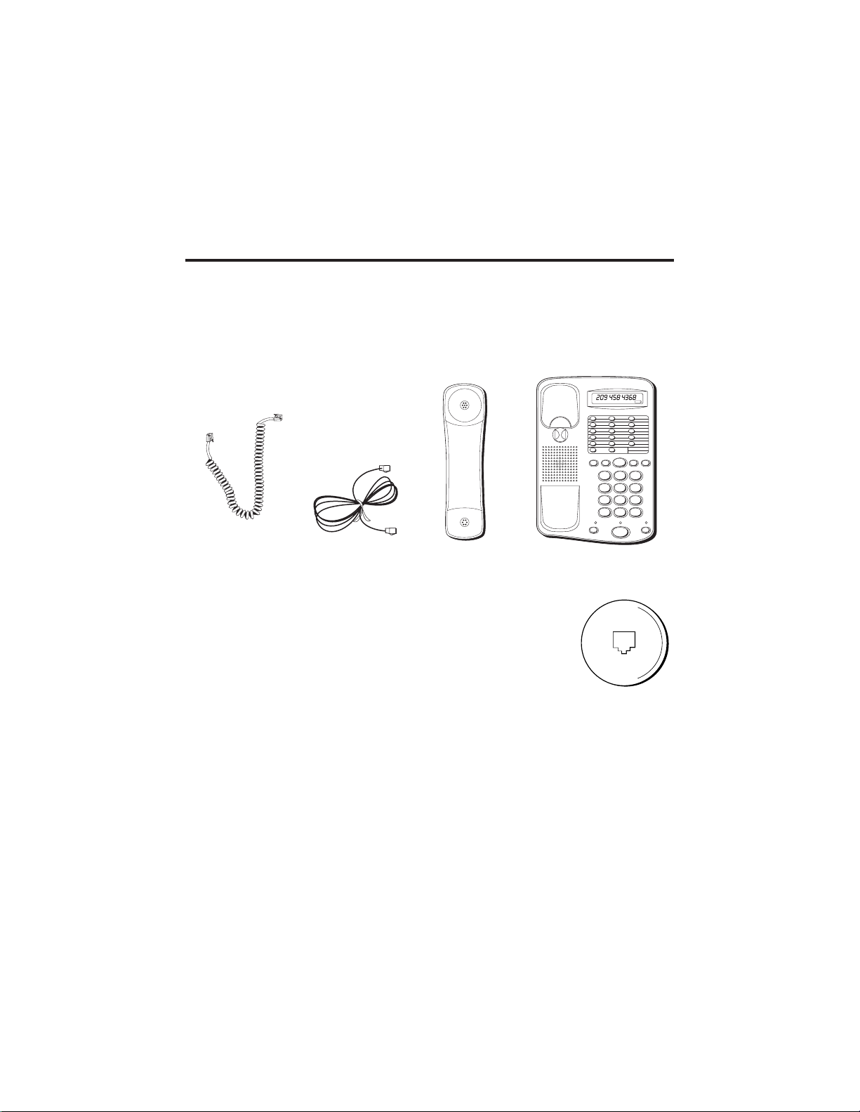
PARTS CHECKLIST
Your package should contain the following items:
Handset cord
Telephone line cord
Handset
Base unit
MODULAR JACK REQUIREMENTS
You need an RJ11 type modular jack, which is the most
common type of phone jack and might look like the one
pictured here. If you don’t have a modular jack, call your local
phone company to find out how to get one installed.
GLOSSARY OF TERMINOLOGY USED IN THIS MANUAL
Hook switch. The part of the phone that pops up to activate the phone line
when the handset is lifted from the base.
Indicator lights. The light located next to each of the function buttons; it shows
you the status of each button (MUTE, SPEAKER, HOLD).
Off-hook. The phone is active, i.e., the handset is out of the cradle.
On-hook. The phone is inactive, i.e., the handset is in the cradle.
2
Page 5
BATTERY POWER
–
+
–
+
–
+
–
+
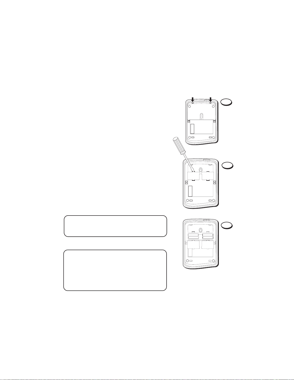
AA BATTERY INSTALLATION/REPLACEMENT
Install 4 AA-size batteries into the bottom of the
phone to provide power for the speakerphone,
the display, the busy redial feature, and in order
to store numbers in memory.
1. Disconnect the telephone line cord from the
LINE jack on the back of the phone.
2. Remove the base plate on the back of the
phone by pressing down on the tabs and
lifting the base plate from the base.
3. Open the compartment cover by putting a
coin or screwdriver behind the tabs of the top
of the cover, and twisting slightly to pop the
cover open.
4. Insert the batteries as shown in the diagram
inside the battery compartment.
5. Close the battery cover.
TIP: If the battery becomes weak and needs to be
replaced, the battery symbol appears in the
display.
1
2
3
NOTE: Periodically replace your batteries to
prevent battery leakage and damage to your
telephone. When discarding batteries, be sure to
dispose of them in the proper manner, according
to your state and local regulations. Remove
batteries when storing this unit for more than one
month.
3
Page 6
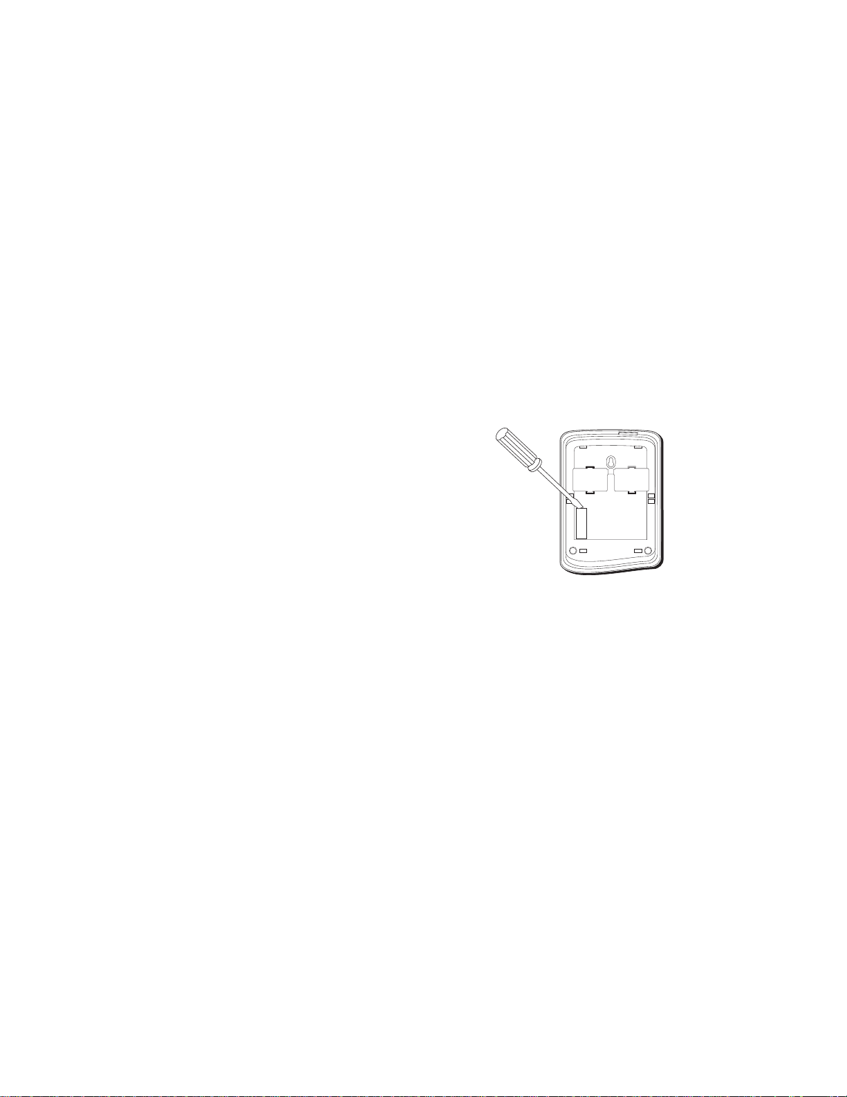
MEMORY BACKUP BATTERY
A 3V lithium battery has already been installed in
your phone to act as a backup when the AA-size
batteries lose their power. The 3V lithium battery
ensures that the numbers you’ve stored in
memory will be retained when the AA-size
batteries are removed or aren’t working properly.
You’ll know you need to replace the 3V lithium
backup battery if memory backup fails when you
remove the AA-size batteries. To replace the 3V
lithium battery:
1. Disconnect the telephone line cord from the
LINE jack on the back of the phone.
2. Remove the plastic cover with a screwdriver to
expose the black battery holder.
3. Use the screwdriver again to pop up either end
of the black battery holder out of the cabinet.
4. Slide the battery holder out of the
compartment and remove the battery from the
black holder.
5. Insert new battery and snap into the black
holder making sure you’ve matched the + and
– polarities on the battery and the holder.
6. Replace the battery holder and make sure that
the keyhole on the holder lines up with the tab
on the cabinet.
7. Replace the plastic cover and plug the
telephone line cord back into the phone.
4
Page 7
TELEPHONE INSTALLATION
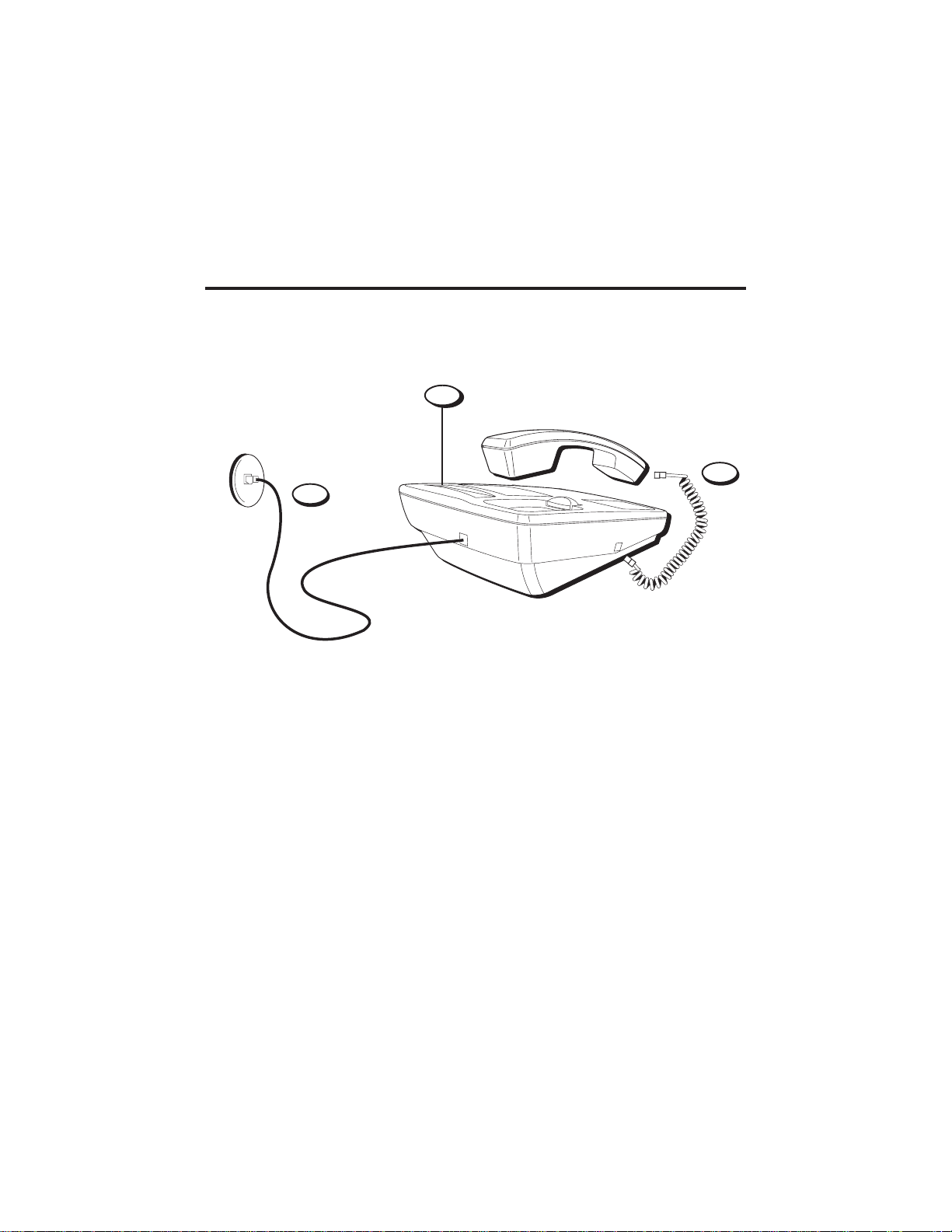
DESKTOP INSTALLATION
2
PULSE/TONE switch
1
3
1. Plug the handset cord into the handset and into the telephone jack on the left
side of the unit.
2. Set the PULSE/TONE switch (located on the side of the unit) to TONE if you
have touch-tone service; set it to PULSE if you have rotary service.
3. Plug the telephone line cord into a modular jack and into the LINE jack on
the back of the unit.
5
Page 8

WALL MOUNT INSTALLATION
1. Pull up the handset hook and rotate it one-half
turn.
2. Remove the base plate from the back by
pressing down on the snap tabs located at the
top, and then lifting the base plate off.
3. Open the battery compartment cover. Thread
telephone line cord through the battery
compartment cover. Plug the telephone line
cord into the LINE jack. Close the battery
compartment cover.
4. Reverse the direction of the base plate and
replace it by putting the tabs into the slots on
the unit first, and then snapping the bottom
tabs into place.
5. Connect the other end of the telephone line
cord into the modular jack on the wall.
6. Slip the mounting holes over the wall plate
posts and slide the unit down firmly into
place. (Wall plate not included.)
7. Set the PULSE/TONE switch (located on the
side of the unit) to TONE if you have touchtone service; set it to PULSE if you have rotary
service.
8. Plug the handset cord into the handset and
into the unit, and then hang up the handset.
1
7
PULSE/TONE switch
2
3
4
LOWER SPEAKER ABR
5
6
LOW
SPEAKER PHONE32 MEMORY
NOTE: The easiest way to fit the telephone line
cord into the base plate is to leave it wrapped
up. Just unwrap enough cord to reach the
LINE jack and the modular wall jack.
6
AREA CODE PHONE NUMBER
STORE LOWER
BUSY/REDIAL REDIAL ALARMPAUSEFLASH
DEF2ABC
1
3
GHI5JKL6MNO
4
PQ
8
TUV
RS
7
8
OPER
*
TONE
0
MUTE HOLD
SPEAKER
WX
YZ
9
#
Page 9

SETUP
SETTING THE RINGER VOLUME
The VOLUME HI/LO/OFF switch, located on the
left side of the unit controls the ringer volume.
• OFF — The phone does not ring. Use the OFF
setting when you don’t want to be disturbed.
If you have an answering system, it still
answers the call.
• LO — Use LO for a soft ring.
• HI — Use HI for a loud ring.
SETTING THE VOLUME LEVELS
The VOLUME switch, located on the right side of
LO VOLUME HI
• •
PULSE TONE
• •
the unit controls the speaker volume for the
handset and speaker. Set to desired level.
VOLUME HI/LO switch
THE DISPLAY
The display shows you information, such as the current time, the duration of a
call, or the phone number you are currently dialing (the last 12 digits dialed
appear in the display).
Display item Meaning
STORE Unit is storing a number in memory.
LOWER Unit is storing a number in lower memory.
ALARM Alarm is active.
SPEAKER Speakerphone is active.
HOLD Phone is on hold.
LOW
ABR Unit is Auto Busy Redialing.
7
Battery is dead or low and needs to be replaced.
Page 10

SETTING THE DATE AND TIME
You can set the clock by following these steps:
1. Press the STORE button.
2. Press the HOLD button.
3. Press the appropriate digits for the following:
Display item Setting date and time
XX Enter the month (must be
YY Enter the day (must be 2
*
# Enter for PM.
HH Enter the hour (must be 2
MM Enter minutes (must be 2
When you enter time and date settings, you
must use two digits. For example, to enter 2:05
April 2nd, you would enter 04, 02 for April 2nd
and 02, 05 for 2:05.
2 digits)
digits)
Enter for AM.
digits)
digits)
XX - YY_*/# HH-MM
HOLD
Enter the date and time information. Entries must be two digits.
STORE button
SPEAKER PHONE30 MEMORY
BUSY/REDIAL
ABC
2
TUV
8
OPER
0
SPEAKER
AREA CODE PHONE NUMBER
REDIAL
ALARMPAUSEFLASH
DEF
3
WX
YZ
9
#
STORE LOWER
1
GHI5JKL6MNO
4
PQ
RS
7
*
TONE
MUTE HOLD
NOTE: If the unit goes off-hook during
programming, the changes will be lost.
HOLD button
8
Page 11

TELEPHONE OPERATION
You can use the telephone by speaking and listening through the handset, or by
using the speakerphone feature.
SPEAKERPHONE LOCATION AND USE GUIDELINES
For best speakerphone performance, avoid the following:
• Areas with high background noise. (The microphone might pick up these
sounds and prevent the speakerphone from going into the receiving mode
when you finish talking.)
• Surfaces affected by vibration.
• Recessed areas such as in a corner, under a cupboard, or next to a cabinet,
which can generate an echo effect.
Note the following guidelines when you use the speakerphone:
• The speakerphone works similar to a two-way radio in that you can only
listen or talk at one time.
• Stay reasonably close to the phone so that you can be clearly heard by the
person to whom you are talking.
USING THE SPEAKERPHONE
To use the speakerphone, press the
SPEAKER button and the phone
automatically goes into speakerphone
mode.
PLACING A CALL
3. Press SPEAKER.
2. Dial the phone number you want to call.
3. Press SPEAKER again to hang up.
GHI5JKL6MNO
PQ
RS
*
TONE
MUTE HOLD
SPEAKER button
DEF
ABC
2
1
4
7
TUV
OPER
SPEAKER
3
WX
YZ
8
9
#
0
NOTE: You must install 4 AA-size
batteries in order for the speakerphone
to work.
9
Page 12

SWITCHING BETWEEN SPEAKER AND HANDSET
1
#
0
OPER
TONE
3
DEF
2
ABC
4
GHI5JKL6MNO
7
PQ
RS
8
TUV
9
WX
YZ
*
BUSY/REDIAL
REDIAL
ALARMPAUSEFLASH
MUTE HOLD
SPEAKER
STORE LOWER
AREA CODE PHONE NUMBER
SPEAKER PHONE30 MEMORY
LOWER SPEAKER ABR
LOW
You can switch between speakerphone and
handset after dialing a number, or anytime during
a conversation.
• Speaker to Handset — Pick up the handset.
• Handset to Speaker — Press SPEAKER; then
hang up the handset.
USING THE FEATURES
This section discusses all of the basic telephone
features.
REDIAL
To quickly redial the last number you called,
press the REDIAL button after you get a dial
tone.
NOTE: When you enter extra numbers after
dialing a phone number (i.e., to access voice menu
systems such as electronic banking), those numbers are also redialed automatically when you press
REDIAL (up to 32 numbers). If you enter more
than 32 numbers, the redial memory is cleared.
If you get a busy signal, you can press REDIAL
again without hanging up to save some time in
redialing the number. (See the following section
regarding the Busy Redial feature to learn how to
make the phone do the dialing for you).
REDIAL button
Page 13

BUSY REDIAL
The Busy Redial feature enables the phone to
automatically dial a number when you get a
busy signal.
When you call and get a busy signal, hang up
the phone and press the BUSY/REDIAL button.
The phone’s speakerphone is activated and the
phone automatically redials the phone number
every 30 seconds (up to 10 times). You’ll hear
the phone automatically dialing through the
speaker.
When the phone detects that the line isn’t busy,
you’ll hear the number ringing through the
speakerphone. You can pick up the handset or
talk through the speaker to talk to the person
you’re calling.
NOTE: The Busy/Redial feature is cancelled if
somebody calls you after you’ve pressed
BUSY/REDIAL
BUSY/REDIAL button
LOWER SPEAKER ABR
STORE LOWER
1
GHI5JKL6MNO
4
PQ
RS
7
*
TONE
MUTE HOLD
BUSY/REDIAL
ABC
2
TUV
8
OPER
0
SPEAKER
LOW
SPEAKER PHONE30 MEMORY
AREA CODE PHONE NUMBER
ALARMPAUSEFLASH
DEF
3
WX
YZ
9
#
REDIAL
HOLD
Use the HOLD button to interrupt a phone
conversation without hanging up; then resume
the conversation on the same phone or an
extension phone.
1. Press HOLD to place the line on hold and
hang up the handset (the HOLD indicator
lights).
2. Press the SPEAKER button or pick up the
handset to resume the conversation.
HOLD button
Page 14

MUTE
Use the MUTE button to interrupt a phone
conversation to talk privately with someone else
in the room.
1. To turn on MUTE, press MUTE on the handset
or speakerphone (the MUTE indicator lights).
2. To turn off MUTE, press MUTE again.
FLASH
Press the FLASH button instead of pressing the
hook switch to activate custom calling services
such as call waiting or call transfer, which are
provided by your local phone company.
TEMPORARY TONE
If you have pulse (rotary) service, and want to
access custom calling services that require tone
dialing (such as getting information from a local
bank), you can use this feature.
1. Dial the phone number.
2. Press the TONE button ( * ) to enable tone
dialing after you have connected to the
custom calling service.
3. When you hang up, the phone automatically
resumes pulse dialing.
LOWER SPEAKER ABR
STORE LOWER
1
GHI5JKL6MNO
4
PQ
RS
7
*
TONE
MUTE HOLD
TONE button
MUTE button
FLASH button
BUSY/REDIAL
ABC
2
TUV
8
OPER
0
SPEAKER
LOW
SPEAKER PHONE30 MEMORY
AREA CODE PHONE NUMBER
ALARMPAUSEFLASH
DEF
3
WX
YZ
9
#
REDIAL
NOTE: Temporary Tone can be stored into a
memory location. See the “Memory Dialing”
section.
12
Page 15

TIMER
BUSY/REDIAL
REDIAL
ALARMPAUSEFLASH
STORE
LOWER
AREA CODE PHONE NUMBER
SPEAKER PHONE30 MEMORY
LOWER SPEAKER ABR
LOW
Whenever you make a call, the elapsed time
appears in the display to show you the duration
of the call.
SETTING THE ALARM
You can set the alarm by following these steps:
1. Press STORE.
2. Press ALARM.
3. Press the appropriate digits for the following:
Display item Setting alarm
*
# Enter for PM.
HH Enter the hour (must be 2
MM Enter minutes (must be 2
NOTE: To set the alarm the phone must be
on-hook.
TURING ON THE ALARM
After you’ve set the alarm time, press the ALARM
button. The alarm time appears in the display for
several seconds and the alarm indicator remains
in the display.
Enter for AM.
digits).
digits.
00-45 P12-01-25
Call timer
Current time
* /# __ HH-MM
ALARM
Enter the alarm information.
TURING OFF THE ALARM
• To turn off the alarm before it rings: press
ALARM (the ALARM indicator turns off).
• To turn off the alarm after it rings: press any
button or pick up the handset. The alarm
sounds for one minute and automatically
stops if you don’t turn off the alarm.
ALARM button
13
Page 16

MEMORY DIALING
1
#
0
OPER
TONE
3
DEF
2
ABC
4
GHI5JKL6MNO
7
PQ
RS
8
TUV
9
WX
YZ
*
BUSY/REDIAL
REDIAL
ALARMPAUSEFLASH
MUTE HOLD
SPEAKER
STORE LOWER
AREA CODE PHONE NUMBER
SPEAKER PHONE30 MEMORY
LOWER SPEAKER ABR
LOW
Each of the 15 memory buttons on the phone contains an upper and lower
memory location. The lower memory is accessed by pressing the LOWER button
located on the memory directory.
Note that if no keys are pressed for 15 seconds, the memory feature
automatically turns off.
Be careful when you store numbers with the phone off-hook, because if you
don’t follow the correct procedures, you might actually call someone instead of
storing their number in memory.
STORING A NUMBER IN UPPER
MEMORY
You can store 15 numbers in upper memory by
following these steps:
1. Press the STORE button (the display clears).
2. Dial the number to be stored – up to 16 digits
(the STORE indicator lights).
3. Press the STORE button again.
4. Press a memory location button to store the
number.
5. Record whose phone number it is on the
memory directory (located under the plastic
cover on the front of the unit).
TIP: If you make a mistake while storing a number
into memory, wait 30 seconds for the feature to
turn off, or press SPEAKER or pick up handset to
get a dial tone and hang up again.
14
STORE button
Memory location buttons
Page 17

STORING A NUMBER
1
#
0
OPER
TONE
3
DEF
2
ABC
4
GHI5JKL6MNO
7
PQ
RS
8
TUV
9
WX
YZ
*
BUSY/REDIAL
REDIAL
ALARMPAUSEFLASH
MUTE HOLD
SPEAKER
STORE LOWER
AREA CODE PHONE NUMBER
SPEAKER PHONE30 MEMORY
LOWER SPEAKER ABR
LOW
IN
LOWER MEMORY
You can store another 15 numbers in lower
memory:
1. Press the STORE button.
2. Dial the number to be stored.
3. Press the STORE button again.
4. Press the LOWER button followed by a
memory location button to store the number
in that button’s lower memory.
5. Record whose phone number it is on the
memory directory located under the plastic
cover on the front of the unit.
INSERTING A PAUSE IN
DIALING SEQUENCE
THE
Press the PAUSE button while storing a number
in memory to insert a delay in the dialing
sequence when a pause is needed to wait for a
dial tone (for example after you dial 9 for an
outside line, or to wait for a computer access
tone). Each pause counts as 1 digit in the dialing
sequence.
LOWER button
PAUSE button
15
Page 18

VIEWING A STORED NUMBER
You can view a number stored in memory without completing the call:
• When you're not using the phone (handset in cradle, speakerphone is
inactive) — Press the memory location button or LOWER and the memory
location button.
CHANGING A STORED NUMBER
To change a stored number, replace it with a different number using the
procedure for storing a number. Remember to update your memory directory
when you make changes.
CLEARING A STORED NUMBER
To clear a stored number, press STORE twice and press the memory location
button that you want to clear.
DIALING A STORED NUMBER
Dial numbers from memory when using the handset or speakerphone.
When you get a dial tone, press the memory location button you want to dial for
upper memory numbers, or press LOWER and then the memory location button
for numbers in lower memory.
CAUTION: If you make test calls to emergency numbers, remain on the line and
explain the reason for the call to the dispatcher. Also, make these calls in off-peak
hours, such as early morning or late evening.
16
Page 19

TROUBLESHOOTING GUIDE
Problem Solution
No dial tone when • Check hook switch. Does it pop up when you pick up
is you pick up handset handset?
Can't hear other party • Check speaker volume.
Can’t be heard by • Make sure handset cord is securely plugged in.
other party
Phone doesn’t ring • Check RINGER volume.
Low speaker volume • Check the volume setting.
LOW Battery Symbol appears • Batteries are dead or not installed. Replace the batteries.
LOW
• Make sure phone line cord is connected.
• Make sure phone cord is securely plugged in.
• Make sure MUTE indicator is off.
• Could have too many phones on one line. (See FCC
registration information regarding REN)
Memory dialing • Make sure you entered numbers correctly. (See
“Memory Dialing.”)
17
Page 20

SERVICE
The FCC requires this product be serviced only by the manufacturer or its
authorized service agents. In accordance with FCC requirements, changes or
modifications not expressly approved by Thomson Consumer Electronics could
void the user’s authority to operate this product. For instructions on how to
obtain service, refer to the warranty included in this guide or call customer
service, telephone number: 800-448-0329.
Attach your sales receipt to the booklet for future reference or jot down the date
this product was purchased or received as a gift. This information will be
valuable if service should be required during the warranty period.
Purchase date _________________________________________________
Name of store_________________________________________________
GENERAL PRODUCT CARE
To keep your speakerphone working and looking good, follow these guidelines:
• Avoid putting it near heating appliances and devices that generate electrical
noise (for example, motors or fluorescent lamps).
• DO NOT expose to direct sunlight or moisture.
• Avoid dropping the unit and/or other rough treatment.
• Clean with a soft cloth.
• Never use a strong cleaning agent or abrasive powder because this will
damage the finish.
• Retain the original packaging in case you need to ship it at a later date.
18
Page 21

INDEX
A
Alarm 12
B
Base plate, removing 3, 5
BUSY REDIAL button 10
Busy Redial feature 9–10
C
Cleaning the phone 18
D
Display messages
ABR 6
Alarm 6
Hold 6
Low battery 6
Lower 6
Speaker 6
Store 6
Index will be updated for final
F
FLASH button 11
H
HOLD button 10
I
Installation
desktop 4
wallmount 5
L
LOWER button 14
lower memory,
storing in 14
M
Memory location, upper and
lower 13,14
O
Off-hook 2
On-hook 2
P
Product care 18
R
REDIAL button 9
Redial feature 9
S
SPEAKER button 8-10
STORE button 7,12,13, 14
Stored numbers,
changing 15
Stored numbers,
clearing 15
Stored numbers, dialing 15
Switching between speaker
and handset 8
T
Temporary Tone feature 11
TONE button 11
U
Upper memory, storing in
13
19
Page 22

LIMITED WARRANTY
What your warranty covers:
• Any defect in materials or workmanship.
For how long after your purchase:
• Two years.
(The warranty period for rental units begins with the first rental or 45 days from date of shipment to the rental
firm, whichever comes first.)
What we will do:
• Provide you with a new, or at our option, a refurbished unit.
• The exchange unit is under warranty for the remainder of the original product’s warranty period.
How to make a warranty claim:
• Properly pack your unit. Include any cables, etc., which were originally provided with the product. We
recommend using the original carton and packing materials.
• Include in the package evidence of purchase date such as the bill of sale. Also print your name and address
and a description of the defect. Send standard UPS or its equivalent to:
Thomson Consumer Electronics, Inc.
Product Exchange Center
32 Spur Drive
El Paso, Texas 79906
• Pay any charges billed to you by the Exchange Center for service not covered by the warranty.
• A new or refurbished unit will be shipped to you prepaid freight.
What your warranty
• Customer instruction. (Your Owner’s Manual provides information regarding operating instructions and user
controls. For additional information, ask your dealer.)
• Installation and set-up service adjustments.
• Batteries.
• Damage from misuse or neglect.
• Products which have been modified or incorporated into other products.
• Products purchased or serviced outside the USA.
• Acts of God, such as but not limited to lightning damage.
Product Registration:
• Please complete and mail the Product Registration Card packed with your unit. It will make it easier to contact
you should it ever be necessary. The return of the card is not required for warranty coverage.
How state law relates to this warranty:
• This warranty gives you specific legal rights, and you may have other rights which vary from state to state.
If you purchased your product outside the USA:
• This warranty does not apply. Contact your dealer for warranty information.
does not
cover:
Model 2-9382
20631670-0001 (Rev. 1 E/S)
97-10
Printed in China
P.O. Box 1976, Indianapolis, IN 46206
© 1997 Thomson Consumer Electronics, Inc.
Trademark(s) ® Registered
Marca(s) Registradas
 Loading...