

Page 1
User Manual
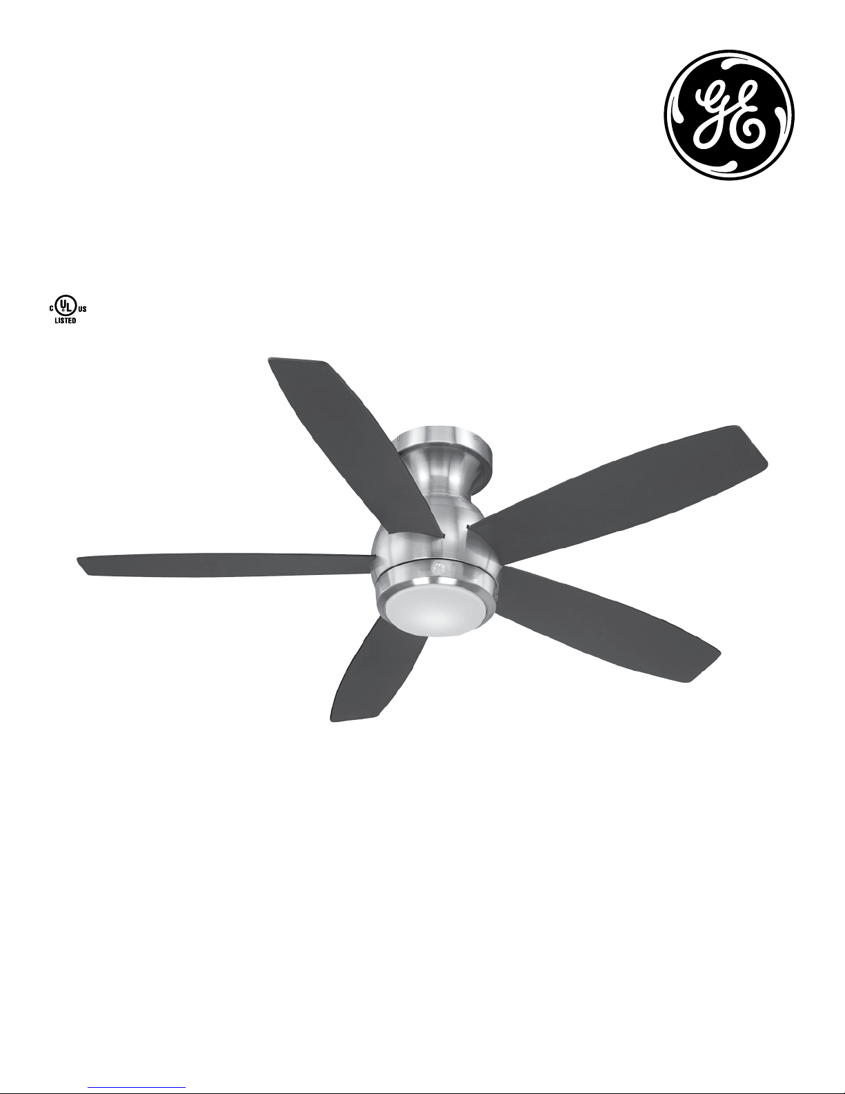
1.3 m (52 in.)
LED Lighted Ceiling Fan
MODEL: 20543
ITM./ART. 4751611
120V 60Hz, MADE IN CHINA
Customer Assistance
1-866-885-4649
Contact a qualified electrician or call the Customer Care Service Team at 1-866-885-4649
Customer Service hours of operation are 9:00AM-5:00PM EST -Monday-Friday
1
Page 2
Safety Rules
1. To reduce the risk of electric shock, insure electricity has
been turned off at the circuit breaker or fuse box before
beginning.
2. All wiring must be in accordance with the latest edition of
National Electrical Code “ANSI/NFPA 70” and local electrical
codes. Electrical installation should be performed by a
qualified licensed electrician.
3. WARNING: To reduce the risk of electrical shock or fire, do
not use this fan with any solid-state fan speed control device.
It will permanently damage the electronic circuitry.
4. CAUTION: To reduce the risk of personal injury, use only
the screws provided with the outlet box.
5. The outlet box and support structure must be securely
mounted and capable of reliably supporting a minimum of
15.9 kg (35 lb.). Use only cUL Listed outlet boxes marked “FOR
FAN SUPPORT.”
6. The fan must be mounted with a minimum of 2.13 m (7 ft.)
clearance from the trailing edge of the blades to the floor.
7. Avoid placing objects in the path of the blades.
8. To avoid personal injury or damage to the fan and other
items, be cautious when working around or cleaning the fan.
9. Do not use water or detergents when cleaning the fan or
fan blades. A dry dust cloth or lightly damped cloth will be
suitable for cleaning.
WARNING: to reduce the risk of
fire, electric shock or personal
injury, mount fan to outlet box
marked acceptable for fan
support the screws provided
with the outlet box.
WARNING: to reduce the risk
of personal injury, do not bend
the blade arms (also referred
to as flanges), when installing
the brackets, balancing the
blades or cleaning the fan. Do
not insert foreign objects in-
between rotating fan blades.
WARNING: to reduce the risk of
fire, electric shock or personal
injury, mount to outlet box
marked “acceptable for fan
support of 15.9 kg (35 lb.) or
less” and use mounting screws
provided with the outlet box.
Most outlet boxes commonly
used for the support of light
fixtures are not acceptable for
fan support and may need to be
replaced. Due to the complexity
of the installation of this fan, a
qualified licensed electrician is
strongly recommended.
10. After making electrical connections, spliced conductors
should be turned upward and pushed carefully up into
the outlet box. The wires should be spread apart with
the grounded conductor and the equipment-grounding
conductor on one side of the outlet box and ungrounded
conductor on the other side of the outlet box.
11. All screws must be checked and re-tightened where
necessary during installation.
2
Page 3
Basic Guidelines For Working With Electricity
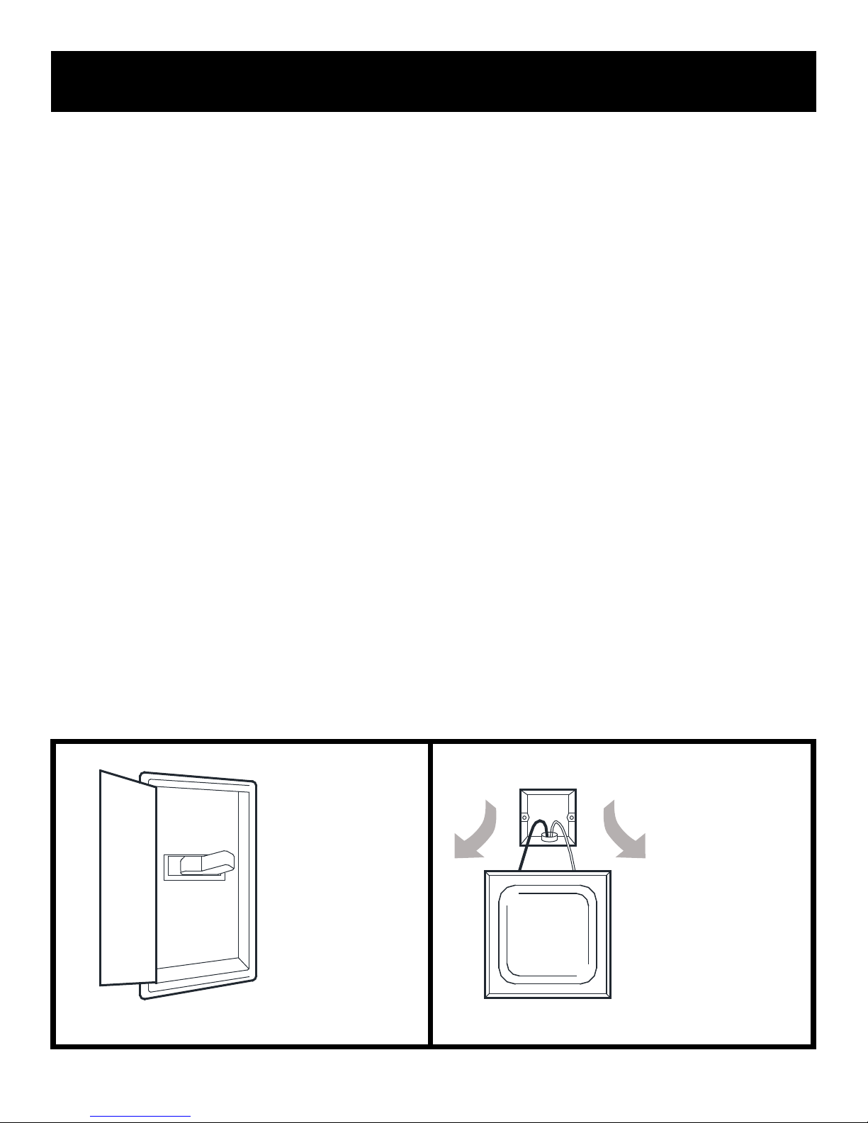
1. Before working on a circuit, go to the main service panel
and remove the fuse or trip the breaker that controls that
circuit.
2. Tape a sign to the panel warning others to leave the circuit
alone while you work.
3. Before touching any wire, use a voltage tester to make
sure it’s not live.
4. Whenever you check for voltage in a receptacle, check
both outlets; each may be controlled by a separate wiring
circuit.
5. When replacing fuses, turn off the main power first. Make
sure your hands and feet are dry, and place one hand behind
your back to prevent electricity from making a complete
circuit through your chest. Touch a plug fuse only by its
insulated rim.
6. Remove cartridge fuses with fuse puller.
7. Use tools with insulated handles and ladders made of
wood or fiberglass.
8. To protect children, place safety cover over any unused
outlets.
Shut off main
power at the
circuit breaker
OFF
MAIN
or fuse panel
before removing
old fixture.
POWER
Remove
old fixture.
Disconnect wire.
3
Page 4
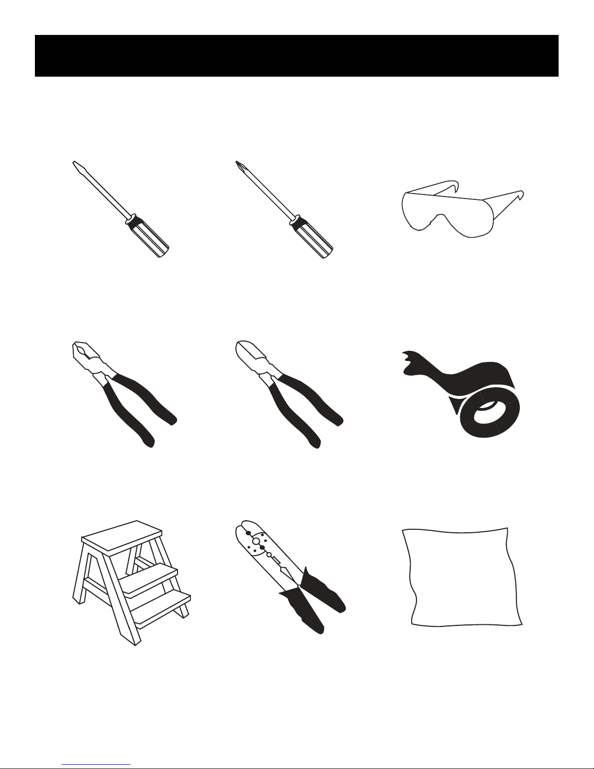
REQUIRED
To Begin / Tools Needed (Not Supplied)
Flathead
Screwdriver
Pliers
Phillips Screwdriver
(4" recommended)
Wire Cutters
Safety Glasses
Electrical Tape
Step Ladder
4
Wire Strippers
Soft Cloth
Page 5

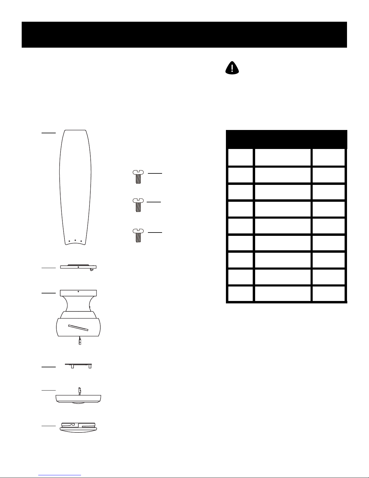
Hardware Included
Carefully unpack and identify each part to make sure you
have everything ready for installation. Lay out each part on
a clean flat area such as a table or floor. Check to make sure
you have the following:
Hardware Bag Remote Control
A
J
B
+
-
K
C
L
D
ATTENTION: parts are not to scale.
PART DESCRIPTION
A
B
C
D
E
F
Wood Screw (Long)
Mounting Screw
Star Washer
Spring Washer
Flat Washer
Blade Screw
QUANTITY
3
2
2
3
3
15+1
replacement
E
F
G
H
G
Fibre Washer
15+1
replacement
M
H
I
J
Plastic Wire Nut
Balance Kit
Transmitter
4
1
1
N
K
L
I
O
M
N
O
AAA Battery
Transmitter Holder
Receiver
Wood Screw (Short)
Plastic Wire Nut
2
1
1
2
6
5
Page 6
Package Contents
Carefully unpack and identify each part to make sure you
have everything ready for installation. Lay out each part on
a clean flat area such as a table or floor. Check to make sure
you have the following:
P
Functional Fasteners
V
W
X
ATTENTION: parts are not to scale.
PART DESCRIPTION
P
Q
R
S
T
U
Set Of Blades
Mounting Bracket
Fan Motor Assembly
Mounting Plate
LED light kit
Glass Shade
QUANTITY
5
1
1
1
1
1
Q
R
S
T
U
V
W
X
Mounting Bracket
Screw
Mounting Plate Screw
Light Kit Mounting
Screw
4
3
3
6
Page 7
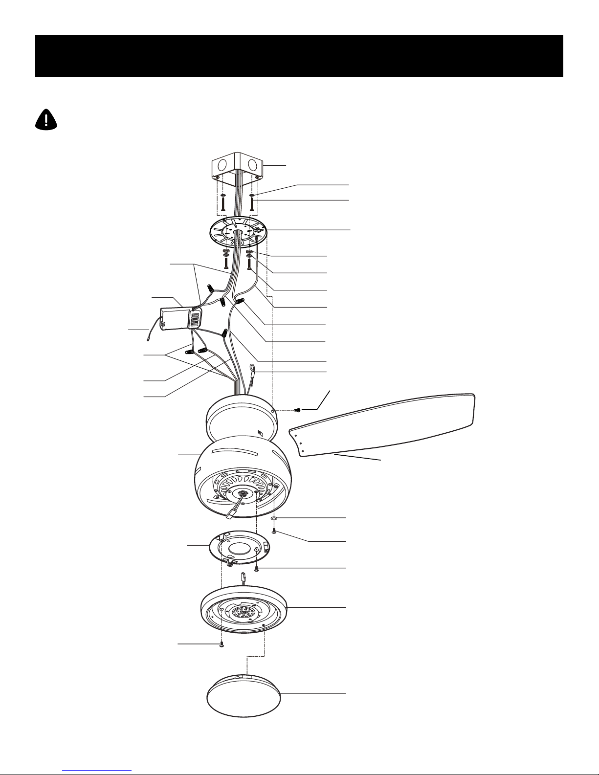
Fan Installation Drawing
WARNING: review important safety instructions before installation.
Outlet Box (Not Provided)
Star Washer
Wood Screw (Long)
Mounting Bracket
Black Wire
Receiver
Antenna Wire
White Wire
Blue Wire
Black Wire
Fan Motor Assembly
Flat Washer
Spring Washer
Mounting Screw
Ground Wire from Mounting Bracket
Plastic Wire Nut
Neutral White Wire
Ground Wire from the Fan Motor Assembly
Safety Cable
Mounting Bracket Mounting Screw
Blade
Fibre Washer
Mounting Plate
Light Kit Mounting Screw
Blade Screw
Mounting Plate Screw
LED Light Kit
Glass Shade
7
Page 8
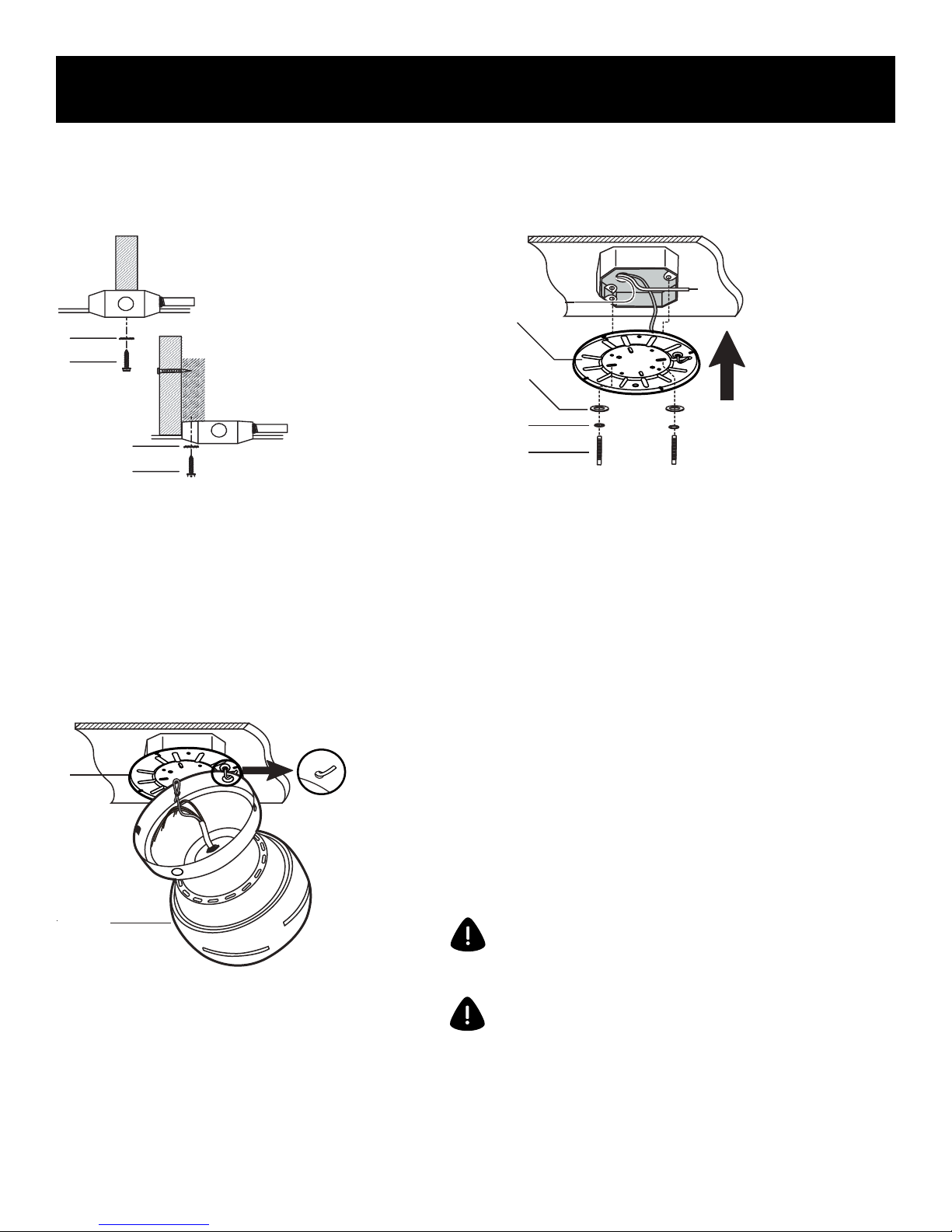
Fan Installation
INSTALLING THE MOUNTING BRACKET
C
A
C
A
Q
E
D
B
1. Use metal outlet box (sold separately)
suitable for fan support. Secure outlet box
directly to the building structure using wood
screws (A) and star washers (C). Outlet box
must support 15.9 kg (35 lb.) min.
HANGING THE FAN
Q
R
2. Install mounting bracket (Q) to the
outlet box in ceiling using the mounting
screws provided with the outlet box (two
additional mounting screws (B), spring
washers (D) and flat washers (E) provided in
the hardware bag).
WARNING: the hook on the mounting plate is only provided
to balance the fan while making the electrical connections.
Do not leave the fan unattended while the fan is hanging
from the hook.
1. Lift the fan into position by hanging the
fan motor assembly (R) onto the hook from
the ceiling mounting bracket (Q) allowing it
to hang freely.
8
WARNING: do not stand under the fan while fan is hanging
from the mounting hook and take necessary precautions to
protect floors during the fan installation.
Page 9
Fan Installation
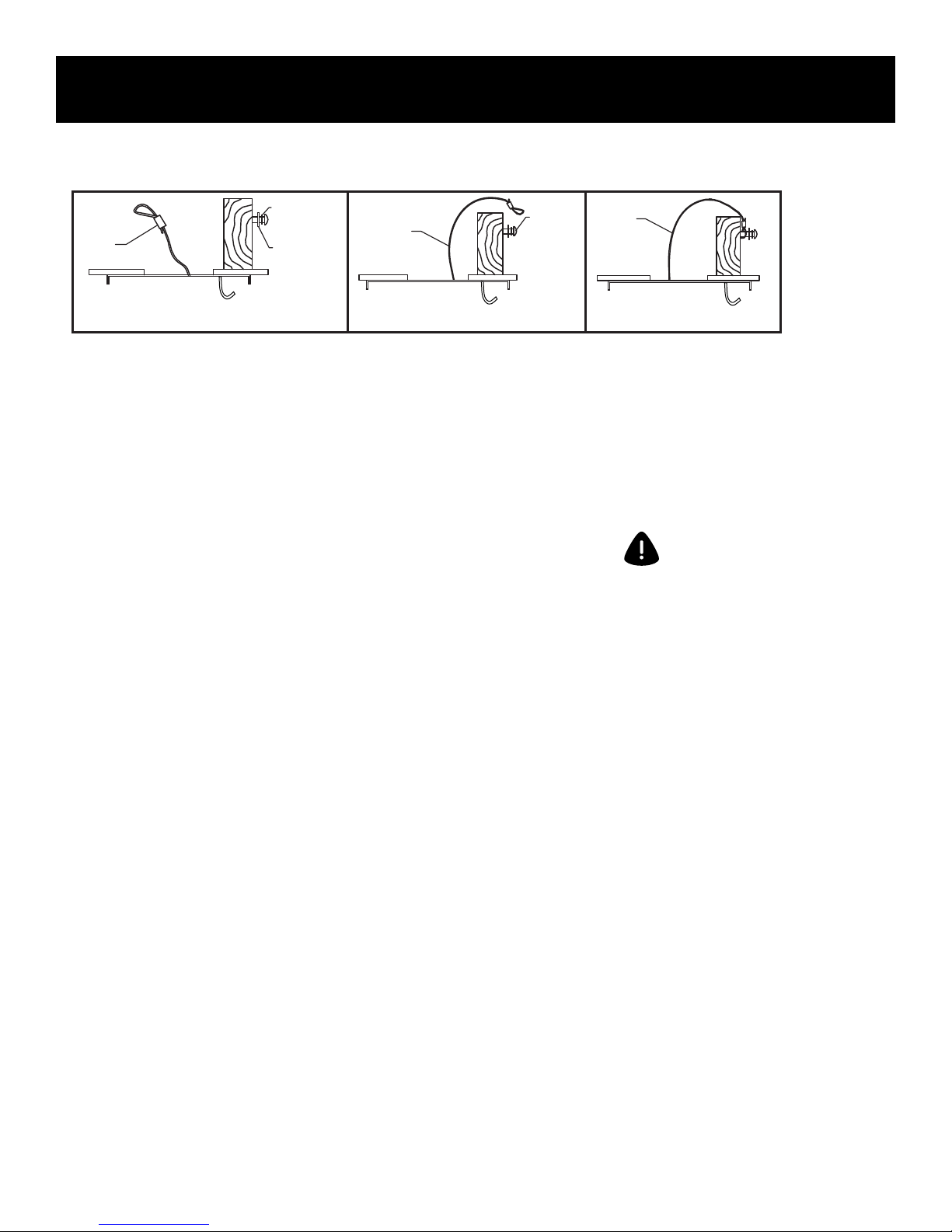
SECURING FAN TO SECONDARY SUPPORT SYSTEM
Spring
washer(D)
Safety
cable
Drive a wood screw (A) and spring washer (D) and flat washer (E) into the side of the brace that holds the outlet box. Leave the 3 mm (1/8 inch) of space
between the support brace and washer. Insert the safety cable through the mounting bracket and one of the holes in the outlet box into the ceiling.
Adjust the length of the safety cable to reach the screw and washers by pulling the extra cable through the cable clamp until the overall length is correct,
put the end of the cable back through the cable clamp, forming a loop at the end of the cable. Tighten the cable clamp securely. Now put the loop in the end
of the safety cable over the wood screw and under the washer. Tighten the wood screw (AA) securely. Make sure the screw, washers and safety cable are
installed using the order pictured above.
Flat
washer(E)
Safety
cable
Wood
screw
(A)
Safety
cable
PREPARING THE ELECTRICAL CONNECTIONS
If you feel you do not have enough electrical wiring
knowledge or experience, have your fan installed by a
licensed electrician.
Follow the steps below to prepare the electrical connections.
After that, conform with the descriptions and diagrams on
next pages to connect the fan to your household wiring. Use
the wire nuts supplied with your fan. Secure the wire nuts
with electrical tape. Make sure there are no loose strands or
connections.
WARNING: to avoid possible electric
shock, be sure electricity is turned
off at the main fuse box before wiring.
9
Page 10
Fan Installation
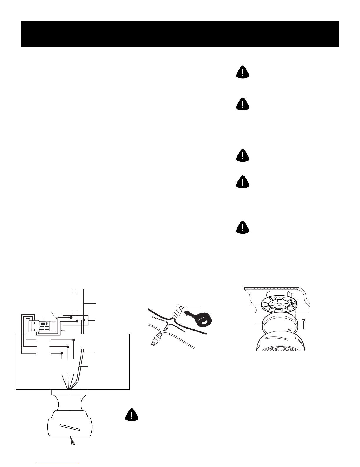
MAKING THE ELECTRICAL CONNECTIONS
Motor to receiver electrical connections: Connect the black
wire from the fan to black wire marked “TO MOTOR L” from
the receiver. Connect the white wire from the fan to the
white wire marked “TO MOTOR N” from the receiver. Connect
the blue wire from the fan to the blue wire marked “For Light”
from the receiver. Secure the wire connections with the
plastic wire nuts (O).
Receiver to house supply wires electrical connections:
Connect the black (hot) wire from the ceiling to the black
wire marked “AC in L” from the receiver. Connect the white
(neutral) wire from the ceiling to the white wire marked “AC
in N” from the receiver. Secure the wire connections with the
plastic wire nuts (H).
If your outlet box has a ground wire (green or bare copper),
connect it to the ground wire from mounting bracket and
ground wire from the fan motor assembly, secure the wire
connection with a plastic wire nut (H); otherwise connect
the ground wire from the fan motor assembly to the ground
wire from mounting bracket, secure the wire connection with
plastic wire nut (H).
WARNING: to avoid possible electric
shock, be sure electricity is turned
off at the main fuse box before wiring.
NOTE: fan must be installed at
a maximum distance of 6 m (20
ft.) from the transmitting unit for
proper signal transmission between
the transmitting unit and fan’s
receiving unit.
CAUTION: do not use wall switch
with dimmer function.
WARNING: check to see that all
connections are tight, including
ground wire, and that no bare wire
is visible at the wire nuts, except for
the ground wire.
WARNING: electrical diagrams are
for reference only. Optional use of
any light kit shall be cUL listed and
marked suitable for use with this fan.
BLACK
M
BLACK
BLUE
WHITE
BLACK for motor
BLUE for light
WHITE for neutral
10
Supply Circuit
BLACK
WHITE
WHITE
GREEN
Ground wire from
BLACK
the fan motor
assembly
BLUE
WHITE
Ground conductor
from ceiling
Outlet box
Ground wire from
mounting bracket
H
To install wire nuts, strip wires 1.9 cm (3/4
in). Line up wires in parallel, insert into
wire nut, hand tight wire nut by twisting
clockwise until snug. Tape around wires
and wire nut. After connecting the wires,
carefully tuck the wire connections and
wires into the canopy.
WARNING: after making the
electrical connections, carefully
unhook the fan and hold the fan
firmly while attaching the fan to the
mounting plate.
Q
R
V
Loosen two (one of each across) of the
four screws (V) from the mounting bracket
(Q) and remove the other two. Remove
the motor assembly (R) from the hook of
mounting bracket (Q) and push up the
motor assembly (R) until the two screws (V)
on mounting bracket (Q) are engaged with
L type slot holes on canopy of the motor
assembly (R). Rotate the motor assembly
(R) slightly until the two screw heads are
in the L type slot holes. Install the two
screws previously removed and tighten all
four screws.
Page 11
Fan Installation
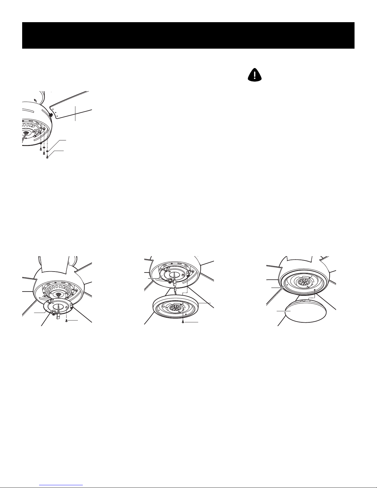
ATTACHING THE FAN BLADES
P
G
F
Insert the blade (P) through the slot in the
bottom band, align the holes in the blade
(P) and the bracket, secure with the blade
screws (F) and fibre washers (G) provided.
Repeat this procedure with the other
blades (P).
INSTALLING THE LIGHT KIT
NOTE: before starting installation,
disconnect the power by turning
off the circuit breaker or removing
the fuse at fuse box. Turning power
off using the fan switch may not be
sufficient to prevent electric shock.
S
W
Remove the 1 of 3 mounting plate screws
(W) from the bottom of motor assembly
(R) and keep it for future use. Loosen the
other 2 screws (do not remove). Place
the key holes on the mounting plate (S)
over the 2 mounting plate screws (W)
previously loosened, turn the mounting
plate (S) until it locks in place at the
narrow section of the key holes. Secure
by tightening the 2 screws previously
loosened and the one previously removed.
S
T
X
Remove the 1 of 3 light kit mounting
screws (X) from the mounting plate (S)
and keep it for future use. Loosen the
other 2 screws (do not remove). While
holding the LED light kit (T) under the fan
motor assembly, make the 2-pin wire
connections: Blue to blue and white to
white. Place the key holes on the LED light
kit (T) over the 2 light kit mounting screws
(X) previously loosened, turn the LED light
kit (T) until it locks in place at the narrow
section of key holes. Secure by tightening
the 2 screws previously loosened and the
one previously removed.
T
U
Raise glass shade (U) up against the light
kit (T) and secure it to fan by twisting glass
(U) clockwise until snug. Do not overtighten.
11
Page 12

Operation Instructions
J
AAA
AAA
1. "Sync" switch:
See " REMOTE CONTROL
PAIRING INSTRUCTIONS"
in Page 14 for details.
J
AAA
AAA
2. “ O " and " I " dip switch:
For this fan, the switch should
be in the " I " position, allowing
for dimming of the light. Place
the switch in the "O" position to
turn the dimming feature off.
J
K
-
+
+
-
3. Install two 1.5-volt AAA batteries (K) provided
in the remote control bag.
Note :
.
To prevent damage to transmitter (J), remove the
batteries if not used for long periods.
.
Replace batteries as a simultaneous set – always replace
the whole set of batteries at one time, taking care not to
mix old and new ones, or batteries of different types.
.
Ensure the batteries are installed correctly with regard to
polarity (+ and -).
.
Please contact your local batteries recycling centre for
proper battery disposal information.
AAA
AAA
Restore power to ceiling fan and test for
4.
proper operation.
7. " " button:
Test for proper operation.
This button controls the light on/off and
brightness settings. Press and release this
button to turn the light ON/OFF.
Press and hold the button to set the desired
brightness. The light will stop adjusting the
brightness when it reaches the maximum or
minimum light settings. Release this button
and press/hold again to adjust the brightness
again.
12
5. “ , , and ” buttons:
These three buttons are used to
set the fan speed as follows:
= low speed
= medium speed
= high speed
8. " " button:
This button delays the light turning off
for approximately 5 seconds, enabling
you to exit your room before the light
turns completely off.
6. " " button:
This button turns the fan off.
Forward Reverse
9. The reverse switch is located on the top
of motor housing. Slide reverse switch to
change fan rotation. Slide the switch to
the left for warm weather operation. Slide
the switch to the right for cool weather
operation.
Note: wait for fan to stop before reversing
the direction of the blade rotation.
Page 13

Operation Instructions
10. Warm weather - (Switch to the left -
Counterclockwise direction) A downward
air flow creates a cooling effect as shown.
This allows you to set your air conditioner
on a higher setting without affecting your
comfort.
IC ID: 11037A-FAN61T3SP
Operation is subject to the following two conditions:
1. The device may not cause interference, and
2. This device must accept any interference, including interference that may cause undesired operation of the device.
11. Cool weather - (Switch to the right -
Clockwise direction) An upward air flow
moves warm air off the ceiling are as
shown. This allows you to set your heating
unit on a lower setting without affecting
your comfort.
N
L
12. Select a location to install your
Transmitter holder (L). Attach the
transmitter holder (L) with the two short
wood screws (N) provided.
13
Page 14

Remote Control Pairing Instructions
REMOTE CONTROL PAIRING INSTRUCTIONS
Important Note : By default, every fan has been pre-programmed at the factory and should be fully
functional once installation is completed. There is no need to perform the paring process.
Should you find the fan or remote control not working or not fully functional after installation or
during use, pairing of the remote control can be done by following the below simple procedures.
Note, however, that there could be other reasons as to why a fan or a remote control is not working:
.
Make sure all wiring connections have been properly made and are secure
.
Make sure batteries are installed correctly in the transmitter
.
Make sure batteries have a full charge or replace with new batteries
.
Make sure all switches of the power supply to the fan motor are turned on
PROCEDURES FOR PAIRING RECEIVER AND TRANSMITTER
These procedures apply if:
.
The remote if not functioning properly, and you want to reset a fan remote control, or
.
You are replacing the original transmitter or receiver, or
You have multiple ceiling fans of the same model in one location and you wish
.
to be able to control them with one remote.
IF USING ONE REMOTE CONTROL TO CONTROL MULTIPLE FANS
1. Turn OFF the power/isolation switch to ALL fans that you would like to program to the same
hand held remote.
2. Remove the battery cover to access the "Sync" switch on the hand held remote.
3. Install two 1.5 V AAA batteries and make sure the polarity of the batteries is correct.
4. Turn on the power/isolation switch to ALL fans.
5. Press the "Sync" switch with the corner of battery cover (you can also use a small screwdriver or
ballpoint pen) to change the frequency settings within 30 seconds after restoring the power.
The lights will flash (on/off) 3 times and remain bright, then the pairing process is complete.
6. Try different speed setting on the transmitter to ensure all the fans are now fully functional. If not,
repeat the process starting from Step 1 again.
TO RESET INDIVIDUAL REMOTE CONTROL FOR EACH FAN / INSTALLING A NEW RECEIVER
Note: If you have more than one fan of the same model but wish to only perform the pairing on
one fan, follow the same steps starting from step 1 to step 6. Make sure to only power ON one
fan at a time, and power OFF all the nearby fans to avoid picking up the same signal.
1. Turn OFF the power/isolation switch to the fan.
2. Remove the battery cover to access the "Sync" switch on the hand held remote.
3. Install two 1.5 V AAA batteries and make sure the polarity of the batteries is correct.
4. Turn on the power/isolation switch to the fan.
5. Press the "Sync" switch with the corner of battery cover (you can also use a small screwdriver or
ballpoint pen) to change the frequency settings within 30 seconds after restoring the power.
The light will flash (on/off) 3 times and remain bright, then the pairing process is complete.
6. Try different speed setting on the transmitter to ensure the fan is now fully functional. if not, repeat
the process starting from Step 1 again.
14
Page 15

The following procedure should
correct most fan wobble. Check
after each step.
Check that all blade and blade
bracket screws are secure.
Most fan wobble problems are
caused when blade levels are
unequal. Check this level by
selecting a point on the ceiling
above the tip of one of the blades.
Measure from a point on the centre
of each blade to the point on the
ceiling. Measure this distance as
shown in figure. Rotate the fan
until the next blade is positioned
for measurement. Repeat for each
blade. Measurements deviation
should be within 3 mm (1/8 in.). Run
the fan for 10 minutes.
Blade Balancing
Use the enclosed Blade Balancing
Kit if the blade wobble is still
noticeable.
15
Page 16

Blade Balancing
The balancing kit should only be used if there is an
unacceptable amount of fan wobble after completing
all the steps in the user manual under “Fan Blades
Assembly.”
1. Turn the fan on and set the speed control setting to a
speed at which the wobble is the greatest.
2. Turn off the fan and allow it to come to a complete
stop. Mark the blades with masking tape number
1-5. Select one blade and place the balance clip on it
halfway between the blade holder and the blade tip on
the trailing edge of the blade.
3. Turn the fan on. Note whether the wobble has
increased or decreased. Turn the fan off, move the clip
to another blade, and retest. Repeat this procedure
on all blades noting the blade on which the greatest
improvement is achieved.
Attach the plastic
clip on blade
4. Adjust the clip on this blade as shown in the
illustration and operate the fan to find the position
where the clip gives the greatest improvement.
5. Remove the clip, clean the area where the weight is
to be added, and install a balancing weight to the top of
the blade along the centre line near the point where the
clip was positioned on the blade.
6. If the fan wobble problem has not been corrected,
you may wish to try to improve the balancing further by
using the balancing clip and additional weights.
Weight
balance
16
Page 17

Safety Instructions
PRODUCT MAINTENANCE
Here are some suggestions to help you maintain your fan.
Because of the fan’s natural movement, some connections
may become loose. Check the support connections, brackets,
and blade attachments twice a year. Make sure they are
secure. (It is not necessary to remove fan from ceiling.)
Clean your fan periodically to help maintain its new
appearance over the years. Use only a soft brush or lint-free
cloth to avoid scratching the finish. The plating is sealed with
a lacquer to minimize discolouration or tarnishing. Do not
use water when cleaning. This could damage the motor, the
wood, or possibly cause an electrical shock.
You can apply a light coat of furniture polish to the wood
blades for additional protection and enhanced beauty. Cover
small scratches with a light application of shoe polish.
There is no need to oil your fan. The motor has permanently
lubricated sealed ball bearings.
WARNING: make sure the power is
off at the electrical panel box before
you attempt any repairs. Refer
to the section “Making Electrical
Connections.”
TROUBESHOOTING
PROBLEM SOLUTION
Fan will not start
Fan sounds noisy
The LED will not light
Remote control
-Check main and branch circuit fuses or breakers.
-Check line wire connections to the fan and switch wire connections in the switch housing
-Check to make sure the dip switches from the transmitter and receiver are set to the same frequency
-Make sure all motor housing screws are snug
-Make sure the screws that attach the fan blade bracket to the motor hub is tight
-Make sure wire nut connections are not rattling against each other or the interior wall
of the switch housing
-Allow a 24-hour “breaking-in” period. Most noises associated with a new fan
disappear during this time.
-If using a ceiling fan light kit, make sure the screws securing the glassware are tight.
Check that the light bulb is also secure.
-Make sure there is a short distance from the ceiling to the canopy. It should not touch
the ceiling.
-Make sure your ceiling box is secure and rubber isolator pads are used between
mounting bracket and outlet box.
-Discontinue the use of the LED light kit.
-Ensure the power supply is turned on.
-Ensure the circuit beaker is to “ON” position.
-Do not connect the fan with a wall mounted variable speed control (s).
-Make sure the dip switches are set correctly.
is a trademark of General Electric Company
and is under license by Safety Quick Lighting & Fans Corp.
4400 North Point Parkway, Suite 154, Alpharetta, GA 30022
17
Page 18

Manuel de l'utilisateur
1,3 m (52 po)
Ventilateur de plafond à lumières DEL
MODÈLE : 20543
ITM./ART. 4751611
120 V 60 Hz, FABRIQUÉ EN CHINE
Service à la clientèle
1-866-885-4649
Veuillez joindre un maître électricien ou téléphoner à l’équipe du service à la clientèle au 1-866-885-4649
Les heures du service à la clientèle sont du lundi au vendredi de 9 h à 17 h HNE
1
Page 19

Consignes de sécurité
1. Afin de réduire le risque de décharge électrique, vous assurer que
l’alimentation électrique est fermée à partir du disjoncteur ou de la
boîte à fusibles avant de commencer.
2. Tous les câbles doivent être conformes au National Electrical
Code « ANSI/NFPA 70 » et aux autres normes d’électricité
appropriées. Toute installation électrique devrait être faite par
un maître électricien.
3. AVERTISSEMENT : Afin de réduire le risque de décharge
électrique ou d’incendie, ne pas utiliser ce ventilateur avec une
télécommande transistorisée pour régler la vitesse du ventilateur.
L’utilisation d’un tel appareil endommage les circuits électroniques
de façon permanente.
4.
MISE EN GARDE : Afin de réduire le risque de blessure corporelle,
utiliser seulement les vis comprises avec la boîte de sortie.
5. La boîte de sortie et la structure de soutien doivent être
solidement installées et capables de supporter un minimum
de 15,9 kg (35 lb). Utiliser seulement les boîtes de sortie classées
UL avec l’indication « FOR FAN SUPPORT. »
6. Le ventilateur doit présenter une distance minimale de 2,13 m
(7 pieds) entre l’extrémité la plus basse des pales et le plancher.
7. Éviter de placer des objets dans la trajectoire des pales.
8. Soyez prudent lors du nettoyage du ventilateur ou lorsque vous
travaillez en sa proximité afin d’éviter les blessures ou
d’endommager le ventilateur et d'autres articles.
9. Ne pas utiliser d’eau ou de détergent pour nettoyer le
ventilateur ou les pales. Un chiffon doux sec ou légèrement
humide est approprié pour le nettoyage.
AVERTISSEMENT : Afin de réduire
le risque d’incendie, de décharge
électrique ou de blessure
corporelle, fixer le ventilateur à
une boîte de sortie indiquant que
cette dernière peut supporter
un ventilateur et les vis comprises
avec la boîte de sortie.
AVERTISSEMENT : Afin de réduire
le risque de blessure corporelle,
ne pas plier les barres (aussi
appelées brides), lors de
l’installation des supports,
l’équilibrage des pales ou le
nettoyage du ventilateur. Ne pas
insérer d’objets entre les pales
en rotation.
AVERTISSEMENT : Afin de réduire
le risque d’incendie, de décharge
électrique, de blessure corporelle,
fixer à une boîte de sortie pouvant
supporter un ventilateur de 15,9 kg
(35 lb) ou moins et utiliser les vis
d’installation comprises avec la
boîte de sortie. La plupart des
boîtes de sortie utilisées pour
soutenir les luminaires sont
inadaptées au soutien d’un
ventilateur et pourraient exiger
un remplacement. À cause de
l’installation complexe de ce
ventilateur, nous recommandons
les services d’un maître électricien.
10. Une fois les connexions électriques complétées, les
jonctions de conducteurs devraient être tournées vers le haut
et insérées soigneusement dans la boîte de sortie. Les câbles
devraient être séparés avec le conducteur de mise à la terre
et le conducteur de protection d’un côté de la boîte de sortie
et le conducteur non mis à la terre de l’autre côté de la boîte
de sortie.
11. Toutes les vis de fixation doivent être vérifiées et resserrées
au besoin avant l’installation.
2
Page 20

Lignes directrices pour le travaux électriques
1. Avant d’entreprendre des travaux sur des circuits électriques,
aller au panneau électrique principal et retirer le fusible ou
déclencher le disjoncteur responsable du circuit.
2. Poser une affiche sur le panneau afin d’éviter que les gens
travaillent ou touchent aux circuits électriques pendant l’installation.
3. Avant de toucher les câbles, utiliser un détecteur de tension pour
vous assurer qu’ils ne sont pas sous tension.
4. Afin de confirmer si un réceptacle est sous tension, vérifier les
deux boîtes de sortie puisqu’elles peuvent être sous la commande
de circuits différents.
5. Fermer l’alimentation électrique principale pour remplacer les
fusibles. Vous assurer que vos mains et vos pieds sont secs et
placer une main derrière le dos afin d’éviter que l’électricité
marque un circuit complet par votre poitrine. Toucher seulement
le fusible de type bouchon par le rebord isolé.
6. Retirer les fusibles à cartouche à l’aide d’un porte-fusible.
7. Utiliser des outils munis de poignées isolées et des échelles
faites de bois ou de fibre de verre.
8. Afin de protéger les enfants, poser des cache-prises sur les sorties
électriques non utilisées.
Fermer
l’alimentation
électrique
principale à partir
OFF
ALIMENTATION
PRINCIPALE
du disjoncteur ou
du panneau à
fusibles avant de
retirer l’ancien
luminaire/
appareil.
Retirer l’ancien
appareil.
Déconnecter le
câble.
3
Page 21

Pour commencer / outils requis (non inclus)
OUTILS REQUIS
Tournevis à
tête plate
Pince
Tournevis à tête
cruciforme
(4 po. recommandé)
Coupe-câble
Lunettes de sécurité
Ruban isolant
Escabeau
4
Outil à dénuder
Chiffon doux
Page 22

Quincaillerie incluse
Déballer soigneusement chaque pièce et les identifier afin
de vous assurer que tous les éléments sont présents pour
l’installation. Disposer les pièces sur une surface plane et
propre comme une table ou un tapis. Vous assurer d’avoir
les éléments suivants :
Trousse de quincaillerie Télécommande
A
B
+
-
C
D
J
K
L
MISE EN GARDE : les pièces ne sont
pas à l'échelle.
Pièce DESCRIPTION QUANTITÉ
A
B
C
D
E
F
Longues vis en bois
Vis de montage
Rondelle étoile
Rondelle élastique
Rondelle plate
Vis à pale
3
2
2
3
3
15+1
remplacements
E
F
G
H
15+1
remplacements
4
1
1
M
G
H
I
J
Rondelle en fibre
Écrou serre-fils en
plastique
Trousse d’équilibrage
Transmetteur
N
K
L
I
O
M
N
O
Pile AAA
Support à émetteur
Récepteur
Vis courtes en bois
Écrou serre-fils en
plastique
2
1
1
2
6
5
Page 23

Contenu
Déballer soigneusement chaque pièce et les identifier afin
de vous assurer que tous les éléments sont présents pour
l’installation. Disposer les pièces sur une surface plane et
propre comme une table ou un tapis. Vous assurer d’avoir
les éléments suivants :
P
Attaches fonctionnelles
V
W
X
MISE EN GARDE : les pièces ne sont
pas à l'échelle.
Pièce DESCRIPTION QUANTITÉ
P
Q
R
S
T
U
Ensemble de pales
Support de fixation
Assemblage du moteur
du ventilateur
Plaque de fixation
Trousse de lumières
DEL
Abat-jour en verre
5
1
1
1
1
1
Q
R
S
T
U
V
W
X
Vis pour support de
fixation
Vis de plaque de
fixation
Trousse de montage
de lumière
4
3
3
6
Page 24

Diagramme d'installation du ventilateur
AVERTISSEMENT : réviser les instructions de sécurité avant de procéder à l’installation.
Boîte de sortie (non incluse)
Rondelle étoile
Longue vis en bois
Support de fixation
Câble noir
Récepteur
Câble d'antenne
Câble blanc
Câble bleu
Câble noir
Assemblage du moteur
du ventilateur
Rondelle plate
Rondelle élastique
Vis de montage
Câble de mise à la terre
Écrou serre-fils en plastique
Câble neutre blanc
Câble de mise à la terre de l’assemblage du moteur
Câble de sécurité
Vis pour le support de fixation
Pale
Rondelle en fibre
Plaque de fixation
Vis de montage de la trousse
de lumière
Vis de pale
Vis de plaque de fixation
Trousse de lumières DEL
Abat-jour en verre
7
Page 25

Installation du ventilateur
INSTALLER LE SUPPORT DE FIXATION
C
A
C
A
Q
E
D
B
1. Utiliser une boîte de sortie en métal (vendue
séparément) apte à soutenir un ventilateur.
Fixer la boîte de sortie directement à la
structure de l’édifice avec les vis à bois (A)
et les rondelles étoiles (C). La boîte de sortie
doit soutenir un minimum de 15,9 kg (35 lb).
SUSPENDRE LE VENTILATEUR
Q
R
2. Poser le support de fixation (Q) à la boîte de
sortie au plafond avec les vis de fixation fournies
avec la boîte de sortie (deux vis de fixation
supplémentaires (B), rondelles élastiques (D) et
les rondelles plates (E) fournies avec la trousse
de quincaillerie).
AVERTISSEMENT : le crochet sur la plaque de fixation sert à
équilibrer le ventilateur lors des connexions électriques.
Ne pas laisser le ventilateur sans surveillance lorsqu’il est
suspendu au crochet.
AVERTISSEMENT : ne pas rester sous le ventilateur lorsqu’il
est suspendu au crochet et prendre les précautions
nécessaires afin de protéger le plancher lors de l’installation
du ventilateur.
1. Soulever le ventilateur en position et fixer en accrochant
l’assemblage du moteur (R) au crochet du support de
fixation situé au plafond (Q) et laisser suspendre.
8
Page 26

Installation du ventilateur
FIXER LE VENTILATEUR AU SYSTÈME DE SOUTIEN SECONDAIRE
Rondelle à
ressort (D)
Câble de
sécurité
Visser une vis à bois (A) et poser une rondelle à ressort (D) et une rondelle plate (E) dans le contrevent qui soutien la boîte de sortie. Laisser un espace
de 3 mm (1/8 po) entre le contrevent de soutien et la rondelle. Passer le câble de sécurité dans le support de fixation et dans un trou de la boîte de sortie
dans le plafond. Régler la longueur du câble de sécurité afin d’atteindre la vis et les rondelles en tirant le câble excédentaire par le serre-câble jusqu’à ce
que la longueur adéquate soit déterminée. Repasser l’extrémité du câble de sécurité dans le serre-câble pour former une boucle. Resserrer solidement
le serre-câble. Maintenant, passer la boucle faite à l’extrémité du serre-câble par-dessus la vis à bois et sous les rondelles. Resserrer solidement la vis à
bois (AA). Vous assurer que la vis, les rondelles et le câble de sécurité sont dans l’ordre illustré ci-dessus.
Rondelle
plate (E)
Câble de
sécurité
Vis à
bois (A)
PRÉPARER LES CONNEXIONS ÉLECTRIQUES
Si vous croyez que vous n’avez pas les connaissances ou
l’expérience suffisantes pour l’installation, faites appel à
Câble de
sécurité
AVERTISSEMENT: Afin d’éviter la
possibilité de décharge électrique,
vous assurer que l’alimentation
électrique est fermée à partir de la
boîte à fusibles avant de procéder
aux connexions.
un maître électricien.
Suivre les étapes ci-dessous pour préparer les connexions
électriques. Respecter les descriptions et les diagrammes
aux pages indiquées pour brancher le ventilateur aux
câbles de la maison. Utiliser les écrous serre-fils en plastique
fournis avec le ventilateur. Fixer les écrous serre-fils avec le
ruban isolant. Vous assurer qu’il n’y a aucun câble ou
connexion de libres.
9
Page 27

Installation du ventilateur
BRANCHEMENTS ÉLECTRIQUES
Connexion électrique du moteur au récepteur : connecter le
câble noir du ventilateur au câble noir indiqué « TO MOTOR L »
du récepteur. Connecter le câble blanc du ventilateur au câble
blanc du récepteur indiqué « TO MOTOR N ». Connecter le câble
bleu du ventilateur au câble bleu du récepteur indiqué « For
Light ». Fixer les connexions avec les écrous serre-fils en
plastique (O).
Connexion électrique du récepteur aux câbles d’alimentation
de la maison : connecter le câble noir (sous tension) du plafond
au câble noir du récepteur indiqué « AC in L ». Connecter le
câble blanc (neutre) du plafond au câble blanc du récepteur
indiqué « AC in N ». Fixer les connexions avec les écrous
serre-fils en plastique (H).
Si la boîte de sortie possède un câble de mise à la terre (vert
ou en cuivre dénudé) connecter ce câble au câble de mise à
la terre du support de fixation et le câble de mise à la terre
de l’assemblage du moteur du ventilateur, fixer la connexion
avec les écrous serre-fils en plastique (H).
AVERTISSEMENT : Afin d’éviter la
possibilité de décharge électrique,
vous assurer que l’alimentation
électrique est fermée à partir de la
boîte à fusibles avant de procéder
aux connexions.
REMARQUE : le ventilateur doit être
installé à une distance maximale de
6 m (20 pieds) de l’unité de
transmission afin d’assurer un signal
optimal entre l’unité de transmission
et l’unité de réception du ventilateur.
MISE EN GARDE : ne pas utiliser un
interrupteur mural avec un gradateur.
AVERTISSEMENT : Vérifier que toutes
les connexions sont solides, incluant
le câble de mise à la terre. Vous assurer
qu’il n’y a aucun câble dénudé visible
par les coinceurs de câble, sauf le câble
de mise à la terre.
AVERTISSEMENT : Les diagrammes
électriques sont à titre de référence
seulement. Si vous utilisez une trousse
de lumière, cette dernière doit être
classée UL et doit comporter une
indication claire qu’elle peut s’utiliser
avec ce ventilateur.
Circuit d’alimentation électrique
Conducteur de
NOIR
M
NOIR
BLEU
BLANC
MOTOR = moteur
LIGHT = lumière
NEUTRAL = neutre
10
BLANC
BLEU
BLANC
NOIR
NOIR
BLANC
terre du plafond
Boîte de sortie
VERT
Câble de mise à la
terre du support
de fixation
Câble de mise à la
terre du moteur du
ventilateur
H
Pour fixer les écrous serre-fils, dénuder les
câbles de 1
en parallèle, insérer les câbles dans les
écrous serre-fils et resserrer solidement en
tournant dans le sens des aiguilles d’une
montre. Fixer le tout avec le ruban isolant.
Une fois les connexions faites, positionner
les câbles et les connexions dans le
couvercle.
AVERTISSEMENT : lorsque les connexions
électriques sont faites, décrocher
soigneusement le ventilateur et le
soutenir pendant que vous fixez le
ventilateur à la plaque de fixation.
9 cm (3/4 po). Aligner les câbles
Q
R
V
Desserrer deux (une opposée à l’autre) des
quatre vis (V) du support de fixation (Q) et
retirer les deux autres. Retirer l'assemblage
du moteur (R) du crochet du support de
fixation (Q) et soulever l’assemblage du
moteur (R) jusqu’à ce que les deux vis (V)
précédemment desserrées s’engagent dans
les ouvertures en forme de L situées sur le
couvercle de l’assemblage du moteur (R).
Pivoter doucement l’assemblage du
moteur (R) jusqu’à ce que la tête des vis soit
bien fixée dans les ouvertures. Poser les
deux vis retirées auparavant et bien serrer
les quatre vis.
Page 28

Installation du ventilateur
FIXER LES PALES
P
G
F
Insérer la pale (P) dans la fente au bas de la bande,
aligner les trous de la pale (P) avec ceux du support
de fixation, fixer avec les vis (F) de la pale et les
rondelles en fibre (G) fournies. Répéter ces étapes
avec les autres pales (P).
REMARQUE : Avant de procéder à l’installation,
débrancher l’alimentation électrique en
fermant le disjoncteur ou en retirant le
fusible de la boîte à fusibles. Simplement
fermer l’alimentation électrique à partir
de l’interrupteur du ventilateur pourrait
être insuffisant pour prévenir une
décharge électrique.
INSTALLER LA TROUSSE DE LUMIÈRE
S
S
W
Retirer 1 des 3 vis de la plaque de fixation (W)
de l’assemblage du moteur (R) et garder pour
usage ultérieur. Desserrer les 2 autres vis (ne
pas retirer les vis). Positionner les encoches
de la plaque de fixation (S) par-dessus les 2 vis
de la plaque de fixation (W) desserrée
précédemment. Tourner la plaque de fixation (S)
jusqu’à ce qu’elle soit fixée dans la partie étroite
des encoches. Fixer en resserrant les 2 vis
desserrées précédemment et la vis retirée
plus tôt.
Retirer 1 des 3 vis de fixation de la trousse de
lumière (X) de la plaque de fixation (S) et garder
pour usage ultérieur. Desserrer les 2 autres vis
(ne pas retirer les vis). En soutenant la trousse
de lumière DEL (T) sous l’assemblage du moteur
de ventilateur, effectuer les connexions de câbles
à 2 broches : bleu à bleu et blanc à blanc. Placer
les encoches de la trousse de lumière DEL (T) sur
les 2 vis de fixation de la trousse de lumière (X)
desserrées précédemment. Tourner la trousse
de lumière DEL (T) jusqu’à ce que le tout soit
engagé dans la partie étroite des encoches.
Fixer en resserrant les 2 vis desserrées
précédemment et la vis retirée plus tôt.
T
T
U
X
Soulever l’abat-jour en verre (U) jusqu’à la
trousse de lumière (T) et fixer au ventilateur
en tournant l’abat-jour de verre (U) dans
le sens des aiguilles d’une montre jusqu’à
ce que le tout soit solide. Ne pas serrer
excessivement.
11
Page 29

Fonctionnement
J
AAA
AAA
1. Touche de synchronisation :
Voir la section « INSTRUCTIONS
POUR JUMELER LA TÉLÉCOMMANDE »
à la page 14 pour les détails.
J
2. Interrupteurs « O » et « I » :
Pour ce ventilateur, l’interrupteur
devrait être à la position « I » afin
de permettre la gradation de
l’éclairage. Placer l’interrupteur à
la position « O » pour fermer le
mode gradateur.
J
K
-
+
+
-
3. Installer deux piles AAA de 1,5 volt (K)
fournies dans le sac de la télécommande.
Remarque :
.
Afin d’éviter d’endommager le transmetteur (J), enlever
les piles si l’appareil n’est pas utilisé pendant de longues
périodes.
.
Remplacer l’ensemble des piles simultanément – toujours
remplacer l’ensemble des piles au même moment, vous
assurer de ne pas mélanger les anciennes et nouvelles
piles ou les différents types de piles.
.
Vous assurer que les piles sont installées correctement
quant à la polarité (+ et -).
.
Veuillez joindre votre centre de recyclage de piles local
pour disposer de vos vieilles piles.
4. Réinitialiser l’alimentation électrique au
ventilateur de plafond et tester son
fonctionnement.
7.
Tester le fonctionnement.
Cette touche allume/éteint la lumière
et règle la gradation de la lumière.
Appuyer et relâcher le bouton pour
allumer ou éteindre la lumière. Appuyer
et maintenir la touche pour obtenir la
luminosité désirée. La lumière arrêtera
de s’ajuster lorsqu’elle aura atteint la
luminosité maximale ou minimale.
Relâcher la touche et appuyer et
maintenir pour régler la luminosité
12
de nouveau.
5. , , et
Ces trois touches sont utilisées pour
régler la vitesse du ventilateur :
= basse vitesse
= vitesse moyenne
= haute vitesse
8.
Cette touche propose un délai de
5 secondes avant d’éteindre la
lumière et vous permet de sortir
de la pièce avant que la lumière
ne s’éteigne.
6.
Cette touche éteint le ventilateur.
Forward Reverse
9. L’interrupteur de marche arrière est situé
sur le dessus du coffret du moteur. Glisser
l’interrupteur à marche arrière pour changer
la direction de la rotation des pales. Glisser
l’interrupteur vers la gauche par temps chaud
et glisser vers la droite par temps frais.
Remarque : attendre que le ventilateur s’arrête
avant de changer la direction de rotation du
ventilateur.
Page 30

Fonctionnement
10. Temps chaud - (interrupteur à gauche
Rotation dans le sens contraire des aiguilles
d’une montre). L’air circule vers les bas
créant ainsi un effet de fraîcheur tel qu’illustré.
Ceci permet de régler l’air conditionné à un
niveau plus élevé sans déranger le confort.
IC ID: 11037A-FAN61T3SP
Le fonctionnement est sujet aux deux conditions suivantes :
1. Cet appareil ne peut causer aucune interférence.
2. Cet appareil doit accepter toute interférence, incluant l’interférence qui peut causer un fonctionnement inattendu de l’appareil.
11. Temps frais - (interrupteur à droite Rotation
dans le sens des aiguilles d’une montre). L’air
chaud est poussé loin du plafond tel qu’illustré.
Ceci permet de régler le chauffage à un niveau
moins élevé sans déranger votre niveau de confort.
12. Choisir un emplacement pour installer
le support d’émetteur (L). Fixer le support
d’émetteur (L) avec deux vis à bois (N)
fournies.
N
L
13
Page 31

Instructions pour jumeler la télécommande
INSTRUCTIONS POUR JUMELER LA TÉLÉCOMMANDE
Important : Par défaut, tous les ventilateurs sont préprogrammés à l’usine et devraient être
fonctionnels une fois l’installation terminée. Le processus de jumelage n’est pas nécessaire.
Si un ventilateur ou une télécommande ne fonctionne pas ou n’est pas entièrement fonctionnel après
l’installation complète ou pendant son usage, vous pouvez jumeler la télécommande en suivant le
processus décrit ci-dessous. Cependant, d’autres éléments peuvent être responsables du mauvais
fonctionnement des appareils :
.
Vous assurer que les connexions de câbles sont bien établies et sécuritaires
.
Vous assurer que les piles sont posées correctement dans le transmetteur
.
Vous assurer que les piles sont entièrement chargées ou remplacer avec des piles neuves
Vous assurer que tous les interrupteurs de la source d’alimentation électrique du ventilateur sont allumés
.
PROCESSUS POUR JUMELER LE RÉCEPTEUR ET LE TRANSMETTEUR
Ces processus doivent être appliqués si :
.
la télécommande ne fonctionne pas correctement et que vous voulez réinitialiser la télécommande
du ventilateur;
.
si vous remplacer le transmetteur ou le récepteur original;
.
si vous possédez plusieurs ventilateurs de plafond d’un même modèle dans un seul endroit et que
vous voulez tous les régler avec une seule télécommande.
SI UNE SEULE TÉLÉCOMMANDE EST UTILISÉE POUR RÉGLER PLUSIEURS VENTILATEURS
1. Fermer l’interrupteur du courant / isolant pour tous les ventilateurs que vous voulez programmer
sur la même télécommande.
2. Enlever le couvercle pour accéder à l’interrupteur de synchronisation de la télécommande.
3. Installer deux piles AAA de 1,5 V et vous assurer que la polarité des piles est correcte.
4. Allumer l’interrupteur du courant / isolant pour tous les ventilateurs.
5. Appuyer sur l’interrupteur de synchronisation en utilisant le coin du couvercle (vous pouvez aussi
utiliser un petit tournevis ou la pointe d’un stylo) pour changer le réglage de la fréquence dans
les 30 secondes suivant la mise au courant. Les lumières clignoteront 3 fois et resteront allumées,
le processus de jumelage sera terminé.
6. Essayer les réglages de vitesse différents sur le transmetteur afin de vous assurer que tous les
ventilateurs sont fonctionnels. Sinon, répéter le processus à partir de l’étape 1.
RÉINITIALISER UNE TÉLÉCOMMANDE INDIVIDUELLE POUR CHACUN DES VENTILATEURS
/ INSTALLER UN NOUVEAU VENTILATEUR
Remarque : Si vous avez plus d’un ventilateur d’un même modèle et voulez seulement jumeler un
ventilateur à la télécommande, suivez les mêmes étapes, soit de 1 à 6. Vous assurer qu’un seul
ventilateur est allumé au même moment et que les autres sont éteints afin d’éviter que les autres
ventilateurs captent le signal.
1. Fermer l’interrupteur du courant / isolant pour le ventilateur.
2. Enlever le couvercle pour accéder à l’interrupteur de synchronisation de la télécommande.
3. Installer deux piles AAA de 1,5 V et vous assurer que la polarité des piles est correcte.
4. Allumer l’interrupteur du courant / isolant pour le ventilateur.
5. Appuyer sur l’interrupteur de synchronisation en utilisant le coin du couvercle (vous pouvez aussi
utiliser un petit tournevis ou la pointe d’un stylo) pour changer le réglage de la fréquence dans les
30 secondes suivant la mise au courant. Les lumières clignoteront 3 fois et resteront allumées, le
processus de jumelage sera terminé.
6. Essayer les réglages de vitesse différents sur le transmetteur afin de vous assurer que tous les
ventilateurs sont fonctionnels. Sinon, répéter le processus à partir de l’étape 1.
14
Page 32

Équilibrage des pales
Ce procédé devrait corriger la
plupart des déséquilibres.
Vérifier suite à chaque étape.
Vous assurer que chaque pale et
que les vis du support de fixation
des pales sont bien fixées.
Les problèmes de déséquilibre sont
causés quand les niveaux des pales
sont inégaux. Vérifier ce niveau en
choisissant un point au plafond
situé au-dessus de l’extrémité
d’une des pales. Mesurer à partir
d’un point au centre de chaque
pale au point au plafond. Mesurer
cette distance comme indiqué au
diagramme. Tourner le ventilateur
jusqu’à ce que la prochaine pale
soit en position pour mesurer.
Répéter le processus pour chacune
des pales. Les déviations de mesures
ne devraient pas dépasser 3 mm (1/8 po).
Faire fonctionner le ventilateur pendant
10 minutes.
Utiliser la trousse d’équilibrage de pales
comprise si le déséquilibre persiste.
15
Page 33

Équilibrage des pales
Utiliser seulement la trousse d’équilibrage si le
ventilateur de plafond oscille excessivement et
que vous avez effectué toutes les étapes notées
dans le manuel de l’utilisateur sous la rubrique
« Fixer les pales ».
1. Allumer le ventilateur et le faire fonctionner à la
vitesse où il oscille le plus.
2. Éteindre le ventilateur et le laisser s’arrêter
complètement. Marquer les pales de 1 à 5 avec du
ruban de masquage. Sélectionner une des pales et
placer la bride d’équilibrage à mi-chemin entre la
partie qui soutient la pale et l’extrémité la plus
proche du plancher.
Allumer le ventilateur de plafond. Observer si
3.
l’oscillation a augmenté ou diminué. Éteindre le
ventilateur, déplacer la bride d’équilibrage et refaire
le test. Répéter ce processus avec chacune des
pales et noter laquelle subit la plus grande
amélioration.
Fixer la bride de
plastique à la pale
4. Replacer la bride d’équilibrage à la pale qui a
démontré la plus grande amélioration. Déplacer
la bride vers l’intérieur ou l’extérieur et faire
fonctionner le ventilateur afin de déterminer la
position optimale de la bride pour réduire l’oscillation.
5. Enlever la bride d’équilibrage et placer un poids
compensateur sur le dessus de la pale à proximité
de l'endroit où la bride était positionnée.
6. Si le problème d’oscillation n’a pas été corrigé, tenter
d’améliorer l’équilibre davantage avec la bride
d’équilibrage et des poids compensateurs supplémentaires.
Poids compensateur
16
Page 34

Consignes de sécurité
ENTRETIEN DU PRODUIT
Quelques suggestions pour bien entretenir votre ventilateur.
À cause du mouvement naturel du ventilateur, il se peut qu’il
y ait un relâchement des connexions. Vérifier les supports de
fixation, la plaque de fixation, et les fixations des pales deux
fois l’an. Vous assurer que tout est sécuritaire. (Il n’est pas
nécessaire d’enlever le ventilateur du plafond.)
Un nettoyage périodique du ventilateur entretiendra son
apparence des années durant. Utiliser un balai doux ou un
chiffon non-pelucheux pour éviter d’égratigner le fini. Le
placage est scellé avec une laque afin de minimiser la
décoloration ou le ternissement. Ne pas nettoyer avec de
l’eau, ceci pourrait endommager le moteur, le bois ou
possiblement causer une décharge électrique.
Appliquer une mince couche de cire à meuble afin de
rehausser la beauté des pales de bois et fournir une
protection supplémentaire. Dissimuler les petites égratignures
avec une application parcimonieuse de cire à chaussures.
Votre ventilateur n’a pas besoin d’être lubrifié. Le moteur
est équipé d’un roulement à bille scellé et lubrifié de façon
permanente.
AVERTISSEMENT : vous assurer
que l’alimentation électrique
est fermée à partir du panneau
électrique avant d’entreprendre
des réparations. Vous référer à la
section « Établir les connexions
électriques ».
DÉPANNAGE
PROBLÈME SOLUTION
Le ventilateur ne
démarre pas
Le ventilateur est
très bruyant
Les lumières DEL ne
s’allument pas
Télécommande
-Vérifier les disjoncteurs et les fusibles de circuits principaux.
-Vérifier la connexion des câbles allant au ventilateur et inverser les connexions dans le coffrage
des interrupteurs.
-Vous assurer que les interrupteurs de l’émetteur et du récepteur sont réglés à la même fréquence.
-Vous assurer que les vis du bâti du moteur sont solidement fixées.
-Vous assurer que les vis qui fixent la plaque de fixation de la pale au moyeu du moteur sont
serrées.
-Vous assurer que les connexions des coinceurs de câble ne s’entrechoquent ni ne touchent
aux côtés du coffrage des interrupteurs.
-Une période de rodage de 24 heures est requise. La plupart des bruits associés à un nouveau
ventilateur disparaîtront.
-Si vous utilisez la trousse de lumière, vous assurer que les vis qui fixent l’abat-jour de verre sont
serrées. Vérifier aussi si l’ampoule est solidement insérée.
-Vous assurer qu’il n’y a qu’une courte distance entre le plafond et le couvercle. Ce dernier ne
doit pas toucher au plafond.
-Vous assurer que la boîte du plafond est solide et que des tampons de caoutchouc isolants
sont bien placés entre le support de fixation et la boîte de sortie.
-Cesser l’utilisation de la trousse de lumières DEL.
-Vous assurer qu’il y a du courant à l’alimentation électrique.
-Vous assurer que le disjoncteur est bien à la position « ON ».
-Ne pas connecter le ventilateur à une commande de vitesses murale.
-Vous assurer que les interrupteurs de l’émetteur et du récepteur sont bien réglés.
est une marque de commerce de la compagnie General Electric
et est utilisée sous licence par Safety Quick Lighting & Fans Corp.
4400 North Point Parkway, Suite 154, Alpharetta, GA 30022
17
 Loading...