

Page 1
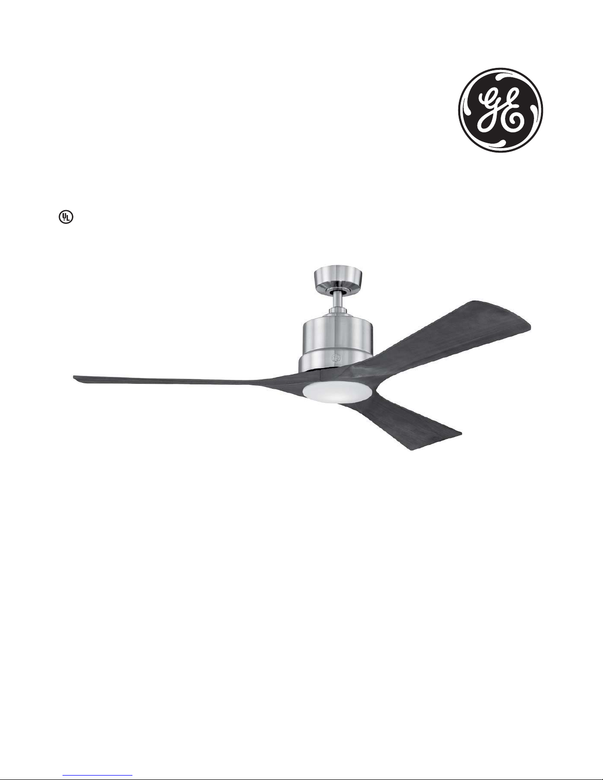
Phantom LED Ceiling Fan
54in (1.37m)
MODEL: 20338
120V 60Hz, MADE IN CHINA
User Manual
Customer Assistance
1-866-885-4649
Contact a qualified electrician or call the Customer Care Service Team at 1-866-885-4649
Customer Service hours of operation are 9:00AM-5:00PM EST -Monday-Friday
customer. service@skyplug.com
Page 2

2
Safety rules
1. To reduce the risk of electric shock, ensure electricity has
been turned off at the circuit breaker or fuse box before
beginning.
2. All wiring must be in accordance with the latest edition of
National Electrical Code “ANSI / NFPA 70” and local electrical
codes.
3. WARNING: to reduce the risk of electrical shock or fire, do
not use this fan with any solid-state fan speed control device.
It will permanently damage the electronic circuitry.
4. CAUTION: to reduce the risk of personal injury, use only the
screws provided with the outlet box.
5. The outlet box and support structure must be securely
mounted and capable of reliably supporting a minimum of
15.9 kg (35 lb.). Use only UL Listed outlet boxes marked “FOR
FAN SUPPORT”
6. The fan must be mounted with a minimum of 7 feet (2.13 m)
clearance from the trailing edge of the blades to the floor.
7. Avoid placing objects in the path of the blades.
8. To avoid personal injury or damage to the fan and other
items, be cautious when working around or cleaning the fan.
9. Do not use water or detergents when cleaning the fan or
fan blades. A dry dust cloth or lightly damped cloth will be
suitable for cleaning.
10. After making electrical connections, spliced conductors
should be turned upward and pushed carefully up into
the outlet box. The wires should be spread apart with the
grounded conductor and the equipment-grounding conductor
on one side of the outlet box and ungrounded conductor on
the other side of the outlet box.
11. All set screws must be checked and re-tightened where
necessary before installation.
WARNING: To reduce the risk of
fire, electric shock or personal
injury, mount fan to outlet box
marked acceptable for fan support
the screws provided with the outlet
box.
WARNING: To reduce the risk
of personal injury, do not bend
the blade arms (also referred to
as flanges), when installing the
brackets, balancing the blades
or cleaning the fan. Do not insert
foreign objects in-between rotating
fan blades.
WARNING: To reduce the risk of
fire, electric shock or personal
injury, mount to outlet box marked
“acceptable for fan support of
15.9 kg (35 lbs.) or less” and use
mounting screws provided with
the outlet box. Most outlet boxes
commonly used for the support of
light fixtures are not acceptable
for fan support and may need to
be replaced. Due to the complexity
of the installation of this fan, a
qualified licensed electrician is
strongly recommended.
Read and Save These Instructions
12. This fan is suitable for room sizes up to 225 square feet
(20.9 square meters).
Vaulted ceiling
angle is not to
exceed 11 degrees.
blade edge
7 feet
(2.13m)
(76 cm)
30
inches
Page 3
3
Basic guidelines for working with electricity
1. Before working on a circuit, go to the main service panel
and remove the fuse or trip the breaker that controls that
circuit.
2. Tape a sign to the panel warning others to leave the circuit
alone while you work
3. Before touching any wire, use a voltage tester to make
sure it’s not live.
4. Whenever you check for voltage in a receptacle, check
both outlets-each may be controlled by a separate wiring
circuit.
5. When replacing fuses, turn off the main power first. Make
sure your hands and feet are dry, and place one hand behind
your back to prevent electricity from making a complete
circuit through your chest. Touch a plug fuse only by its
insulated rim.
6. Remove cartridge fuses with fuse puller.
7. Use tools with insulated handles and ladders made of
wood or fiber glass.
8. To protect children, place safety cover over any unused
outlets.
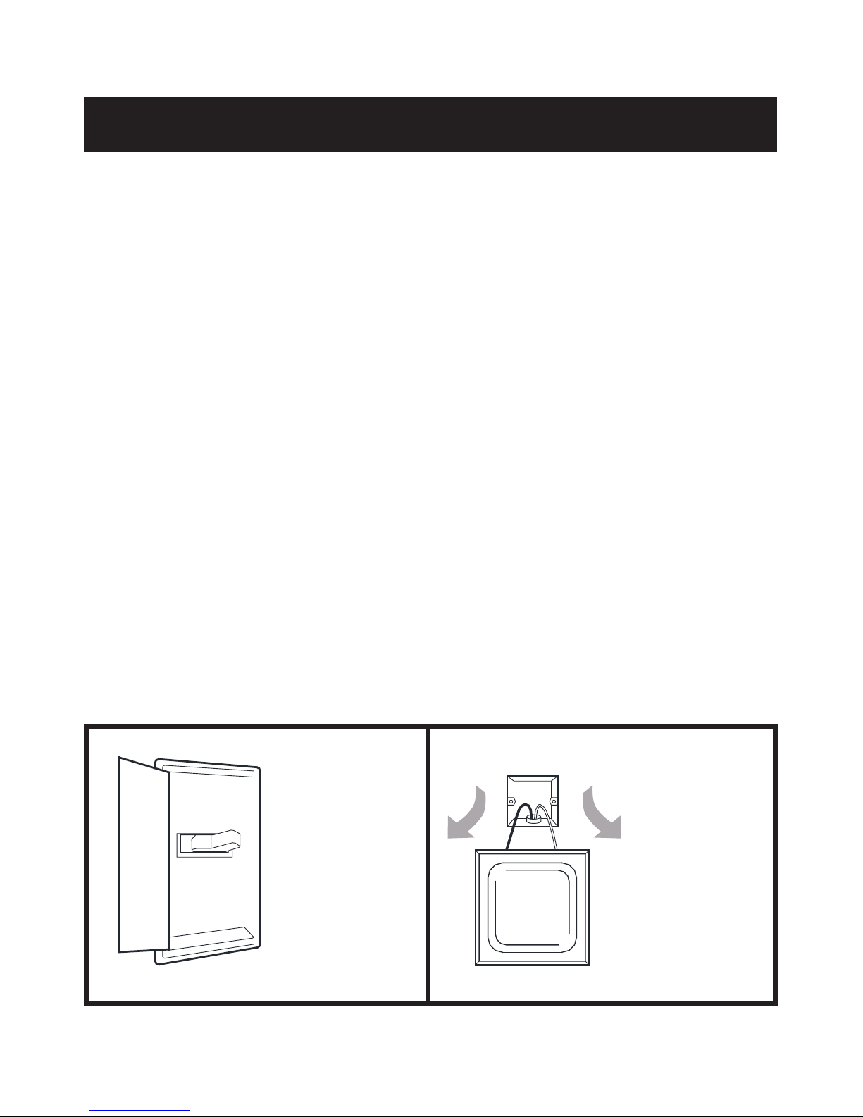
Shut off main
power at the
circuit breaker
or fuse panel
before removing
old fixture.
Remove
old fixture.
Disconnect wire.
OFF
MAIN
POWER
Page 4

4
To begin / tools needed (not supplied)
REQUIRED
Flathead
Screwdriver
Pliers
Step Ladder
Phillips Screwdriver
(4" recommended)
Wire Cutters
Wire Strippers
Safety Glasses
Electrical Tape
Soft Cloth
Page 5
5
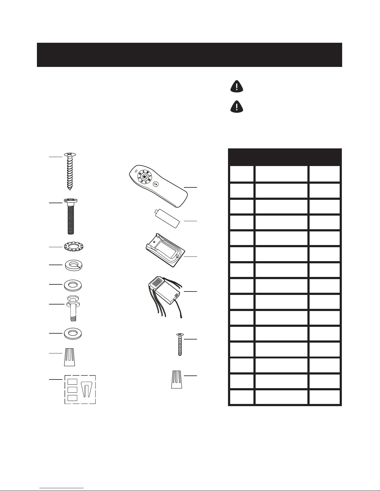
Hardware included
Carefully unpack and identify each part to make sure you
have everything ready for installation. Lay out each par t on
a clean flat area such as a table or floor. Check to make sure
you have the following:
A
A
2
E
E
2
I
I
1
C
C
2
G
G
9+1
9+1
K
K
2
N
N
2
B
B
2
F
F
J
J
1
M
M
1
D
D
2
H
H
4
L
L
1
O
O
5+1
Hardware Bag Remote Control
PART DESCRIPTION
Wood Screw (Long)
Spring Washer
Blade Flat Washer
Transmitter
Receiver
Mounting Screw
Flat Washer
Plastic Wire Nut
AAA Battery
Wood Screw (Short)
Star Washer
Blade Screw
with Spring Washer
Balance Kit
Transmitter Holder
Plastic Wire Nut
QUANTITY
ATTENTION: Parts are not to scale.
NOTE: +1 = Extra quantity supplied
for future use if needed
+
-
Page 6

6
Package contents
Carefully unpack and identify each part to make sure you
have everything ready for installation. Lay out each part on
a clean flat area such as a table or fl oor. (Parts AA-FF are
pre-installed.) Check to make sure you have the following:
P
P
3
T
T
1
Y
Y
1
R
R
1
V
V
1
1
AA
AA
2
DD
DD
1
Q
Q
1
U
U
Z
Z
1
CC
CC
1
S
S
1
W
W
1
BB
BB
2
EE
FF
EE
FF
3
3
Functional Fasteners
PART DESCRIPTION
Set of Blades
Canopy Cover
(preassembled)
Fan Motor Assembly
Glass Shade
Clevis Pin
Mounting Bracket
Ball / 4.5” Downrod
Assembly
Mounting Plate
Canopy Mounting
Screw
Cotter Pin
Canopy (preassembled)
Coupling Cover
LED Light Kit
Collar Set Screw
Mounting Plate Screw
Light Kit Mounting
Screw
QUANTITY
ATTENTION: Parts are not to scale.
Page 7
7
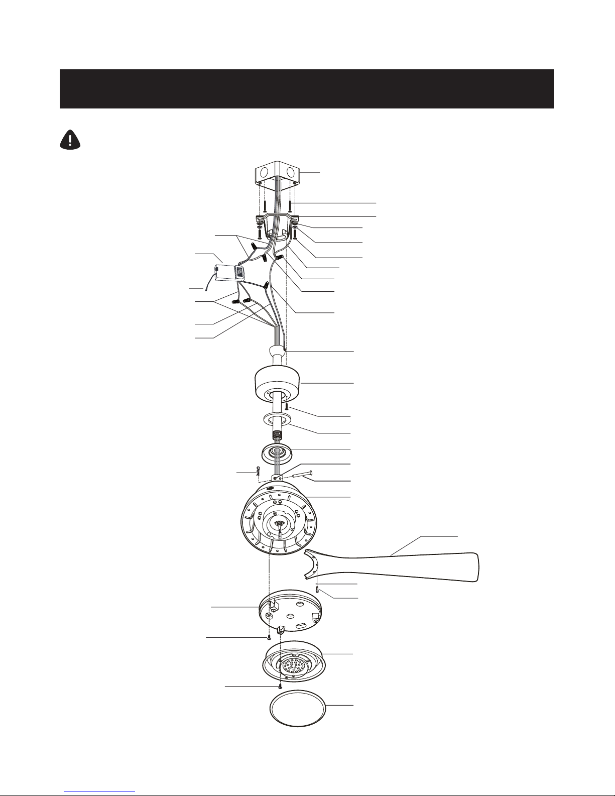
Fan installation drawing
WARNING: Review important safety instructions before installation
Outlet Box (Not Provided)
Hot Wire - Black
Receiver
White Wire
Blue Wire
Black Wire
Cotter Pin
Mounting Plate
Mounting Plate Screw
Light Kit Mounting Screw
Wood Screw (Long)
Mounting Bracket
Flat Washer
Spring Washer
Mounting Screw
Ground Wire from Mounting Bracket
Plastic Wire Nut
Neutral White Wire
Ground Wire from the Fan Motor Assembly
Ball/4.5” (11.4 cm) Downrod Assembly
Canopy
Canopy Mounting Sc rew
Canopy Bottom Co ver
Coupling Cover
Clevis Pin
Collar Set Screw
Fan Motor Assembly
LED Light Kit
Glass Shade
Blade
Blade Screw
w/spring washer
Blade flat washer
Antenna wire
Page 8

8
Fan installation
INSTALLING THE MOUNTING BRACKET
1.
Use metal outlet box (sold separately) suitable
for fan support. Secure outlet box directly to the
building structure using wood screws (A) and star
washers (C). Outlet box must support 15.9 kg (35 lb.)
min.
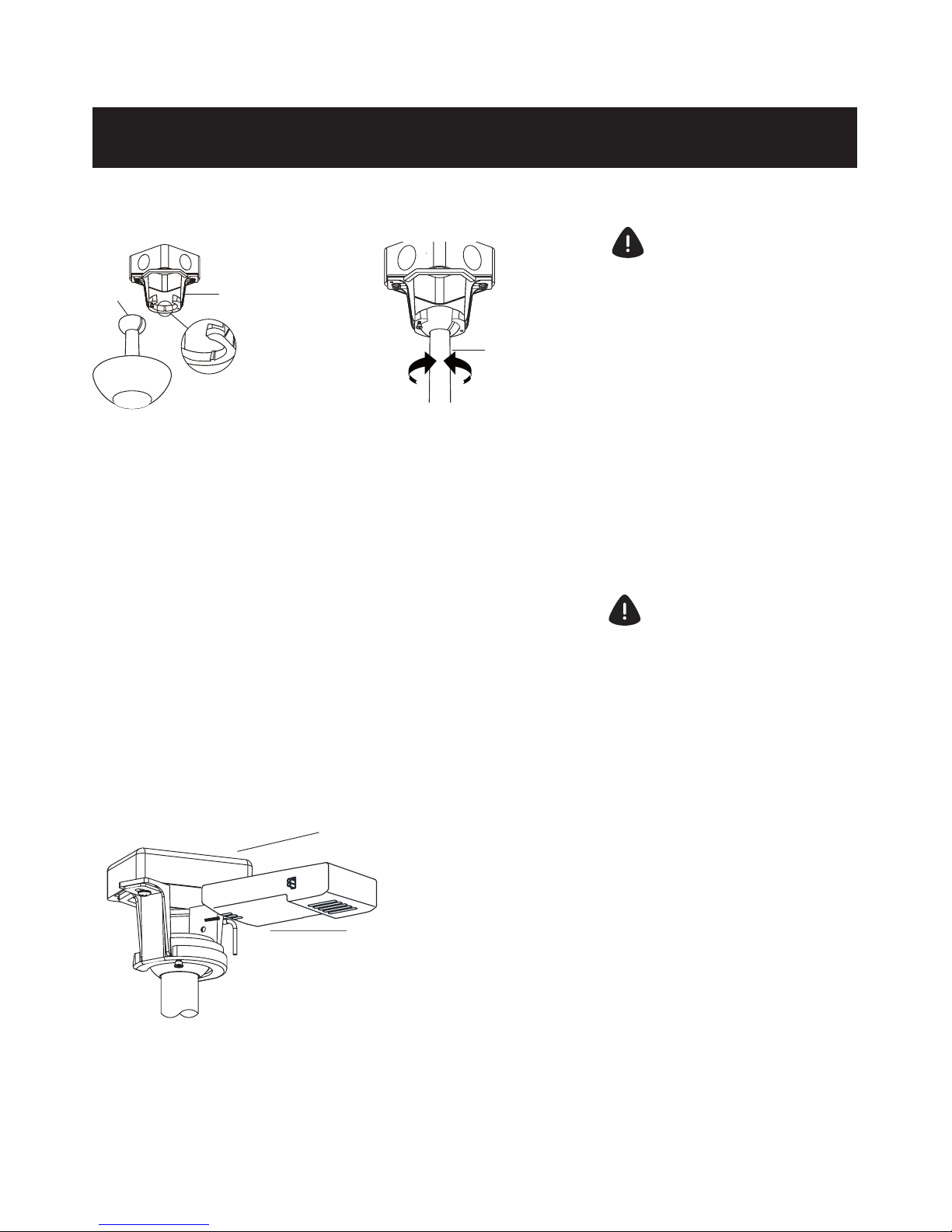
3.
Remove the mounting bracket (Q) from the canopy
(R) by removing the 1 of 2 screws (AA) from the
bottom of the mounting bracket (Q) and loosening
the other one a half turn from the screw head. Next,
turn the canopy (R) counter clockwise to remove the
mounting bracket (Q) from the canopy.
2.
Remove the canopy cover (S) from the canopy (R)
by turning the canopy cov er (S) counter clockwise.
WARNING: do not use an existing mounting bracket
in the outlet box, replace it with the new mounting
bracket that is included with the fan.
4.
Install the mounting bracket (Q) to outlet box in
ceiling using spring washers (D), flat washers (E) and
the mounting screws (B) provided with the outlet box
(two mounting screws, spring and fl at washers are
provided in the hardware bag).
R
S
CC
AA
Q
Q
E
R
AA
D
B
Page 9

9
Fan Installation
HANGING THE FAN
WARNING: Failure to properly
install cotter pin as noted in step
4 could result in fan loosening
and possibly falling.
Remove the clevis pin (CC),
cotter pin (DD) and loosen 2 collar
set screws (BB) from the top of the
fan motor assembly (V).
Take out the setscrew located in
the hanger ball, lower the hanger
ball and remove the cross pin.
Remove the hanger ball from the
hanger ball/downrod assembly (T).
Carefully feed the motor wires
up through the downrod (T).
Thread the downrod (T) into
the collar.
Align the holes at the bottom
of the downrod (T) with the holes
in the collar on top of the fan
motor assembly (V). Caref
ully
insert the clevis pin (CC) through
the holes in the collar and
downrod (T). Be careful not to
jam the clevis pin (CC) against
the wiring inside the downrod (T).
Slip the coupling cover (U),
canopy cover (S) and canopy (R)
onto the downrod (T).
Carefully reinstall the hanger
ball onto the downrod (T), being
sure that the cross pin is in the
correct position, the setscrew
is tightened and wires are not
twisted.
Tighten two set screws (BB)
at top of the fan motor collar
firmly and evenly until fully
engaged. Once set scr
ews have
been installed, tighten each
nut (located on set screws)
completely against motor collar.
Insert the cotter pin (DD)
through the hole near the end of
the clevis pin (CC) until it snaps
into its locked position.
T
CC
DD
BB
V
CC
DD
BB
CC
V
DD
BB
T
T
R
S
U
1.
2.
3.
4.
5.
Page 10
10
Fan installation
HANGING THE FAN
Carefully lift the fan assembly
up to the mounting bracket
(Q) and sit the hanger ball /
downrod assembly (T) in the
mounting bracket (Q) socket.
Make sure the tab on the
mounting bracket socket is
properly seated in the groove
in the hanger ball / downrod
assembly (T). This will help to
balance the ceiling fan.
WARNING: Failure to properly
seat the tab in the groove could
cause damage to wiring.
Q
T
T
If you feel you do not have enough electrical wiring
knowledge or experience, have your fan installed by a
licensed electrician.
Follow the steps below to prepare the electrical connections.
After that, conform with the descriptions and diagrams on
next pages to connect the fan to your household wiring. Use
the wire nuts supplied with your fan. Secure the wire nuts
with electrical tape. Make sure there are no loose strands or
connections.
PREPARING THE ELECTRICAL CONNECTIONS
1.
Insert the receiver (M) into the mounting
bracket (Q) with the fl at side of the receiver
(M) facing the ceiling.
WARNING: To avoid possible
electric shock, be sure electricity
is turned off at the main fuse box
before wiring.
M
Q
6.
7.
Page 11
11
WARNING: To avoid possible electric
shock, be sure electricity is turned
off at the main fuse box before wiring.
NOTE: Fan must be installed at a
maximum distance of 6.1 m (20
ft.) from the transmitting unit for
proper signal transmission between
the transmitting unit and fan’s
receiving unit.
CAUTION: Do not use wall switch
with dimmer function.
WARNING: Check to see that all
connections are tight, including
ground wire, and that no bare wire
is visible at the wire nuts, except for
the ground wire.
WARNING: Electrical diagrams are
for reference only. Optional use of
any light kit shall be UL listed and
marked suitable for use with this fan.
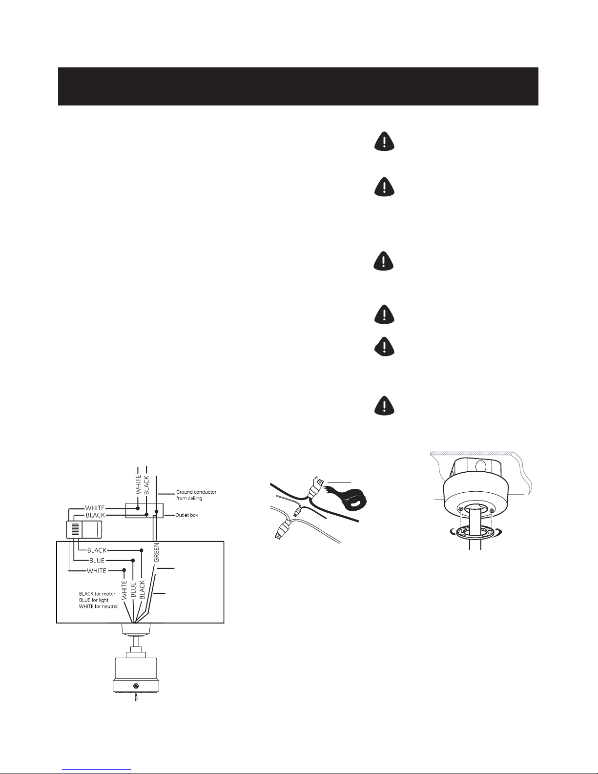
MAKING THE ELECTRICAL CONNECTIONS
Supply Circuit
Motor to receiver electrical connections: Connect the black
wire from the fan to black wire marked “TO MOTOR L” from
the receiver. Connect the white wire from the fan to the
white wire marked “TO MOTOR N” from the receiver. Connect
the blue wire from the fan to the blue wire marked “For Light”
from the receiver. Secure the wire connections with the
plastic wire nuts (H) and electrical tape.
Receiver to house supply wires electrical connections:
Connect the black (hot) wire from the ceiling to the black
wire marked “AC in L” from the receiver. Connect the white
(neutral) wire from the ceiling to the white wire marked “AC
in N” from the receiver. Secure the wire connections with the
plastic wire nuts (H) and electrical tape.
If your outlet box has a ground wire (green or bare copper),
connect it to the ground wire from mounting bracket and
the ground wire from downrod assembly, secure the wire
connection with a plastic wire nut (H); otherwise connect the
ground wire from mounting bracket to the ground wire from
downrod assembly, secure the wire connection with plastic
wire nut (H) and electrical tape.
After connecting the wires, spread them
apart so the green and white wires are on
one side of the outlet box and the black
and blue wires are on the other side.
Carefully tuck the wire connections up into
the outlet box.
Lift the canopy (R) up to the ceiling and
install the canopy (R) to the mounting
bracket (Q) by using the canopy mounting
screws (AA). Attach the canopy bottom
cover (S) to the canopy mounting screw
(AA) heads by inserting the screw heads
into the key slots in the canopy bottom
cover (S) and rotating the canopy bottom
cover (S) clockwise.
NOTE: Adjust the canopy mounting screws
(AA) as necessary until the canopy (R) and
canopy bottom cover (S) are snug.
Fan installation
H
R
AA
S
NOTE : For best remote control
reception, make sure the brown antenna
wire is placed away from the electrial
wires (blue, white and black colors).
Ground wire
from downrod
assembly
Ground wire
from mounting
bracket
Page 12

12
Fan installation
ATTACHING THE FAN BLADES
INSTALLING THE LIGHT KIT
1.
Remove and discard the preassembled plastic motor blocks and screws.
Fasten blade (P) to fan motor assembly (V) using the screws (with spring
washer) (F) and blade flat
washer (G) supplied.
Repeat this procedure with remaining blade assemblies.
1.
Remove 1 of 3 mounting plate screws
(EE) from the mounting ring and loosen
the other 2 screws. (Do not remove)
Place the keyholes on the mounting
plate (W) over the 2 screws previously
loosened from the mounting ring. Turn the
mounting plate (W) until it locks in place at the
narrow section of the key holes. Secure
by tightening the 2 s crews previously
loosened and the one previously removed.
2.
Remove 1 of 3 light kit mounting screws
(FF) from the mounting plate (W) and
loosen the other 2 screws. (Do not remove)
Lift the light kit (Y) up to the framed
mounting plate (W), make the 2-pin wire
connections:
-Blue to blue
-White to white
Place the key holes on the LED light kit
(Y) over the 2 screws previously loosened
from the mounting plate (W), turn LED
light kit (Y) until it locks in place at the
narrow section of the key holes. Secure
by tightening the 2 s crews previously
loosened and the one previously removed.
3.
Raise the glass shade (Z) up against the
LED light kit (Y) and secure it to the fan by
twisting the glass shade (Z) clockwise until
snug. Do not overtighten.
NOTE: Before starting
installation, disconnect the
power by turning off the circuit
breaker or removing the fuse
at fuse box. Turning power
off using the fan switch is not
sufficient to prevent electric
shock.
Z
Y
EE
W
EE
W
FF
Y
WARNING: Make sure to fully secure
the glass shade in place by turning
the shade clockwise until it is locked
in place and can no longer be rotated.
V
G
P
F
G
F
Page 13

Operation Instructions
13
REMOTE CONTROL OPERATIONS
Step 1. Restore power to
ceiling fan.
Step 2. Install two 1.5-volt
AAA batteries provided.
Step 3. Press the “ ” button
located on the front of the
transmitter to operate the fan.
Step 4: Press the “ ” button
to operate the light . A dimmer
feature is provided on the light .
Press and release the button
to turn the light ON or OFF.
Press and hold the button to
set the desired brightness.
In Case Of Interference with Several Fans, You Can
Change the Transmitter Code to Operate This Fan
Only.
Step 1. Switch off the power of the fan.
Step 2. Switch on the power of the fan.
Step 3. Within 30 sec, switch the lock/
unlock switch on the back of the
transmitter to lock " “ position, and
then push the sync “ ” button for
about 5-10 sec, until the fan light kit
flashes 3 times.
See next page for Remote Functions
Operate Fan using Transmitter Code
Pre-Set by Factory
FAN REVERSE FUNCTION
The reversible motor provides upward and downrod air flow for desired air circulation to save energy, see below for the details.
FCC ID: 2AAZPFAN61T3SP1
This device complies with part 15 of the FCC Rules. Operation is subject to the following two conditions:
1. This device may not cause harmful interference, and
2. this device must accept any interference received, including interference that may cause undesired operation.
CAUTION: Any changes or modifications not expressly approved by the party responsible for compliance could void the user’s authority
to operate the equipment.
Note: This equipment has been tested and found to comply with the limits for a Class B digital device, pursuant to part 15 of the FCC Rules.
These limits are designed to provide reasonable protection against harmful interference in a residential installation. This equipment generates,
uses and can radiate radio frequency energy and, if not installed and used in accordance with the instructions, may cause harmf ul interference
to radio communications. However, there is no guarantee that interference will not occur in a particular installation. If this equipment does cause
harmful interference to radio or television reception, which can be determined by turning the equipment off and on, the user is encouraged to try
to correct the interference by one or more of the following measures:
Reorient or relocate the receiving antena.
rease the separation between the equipment and the receiver.
rcuit different from that to which the receiver is connected.
TV technician for help.
Warm weather - Switch to the “Forward”
position: A downward air flow creates a
cooling effect as shown. This allows you
to set your air conditioner on a higher
setting without affecting your comfort.
Cool weather - Switch to the “Reverse”
position: An upward air flow moves warm
air off the ceiling as shown.This allows you
to set your heating unit on a lower setting
without affecting your comfort.
The reverse switch is located on the top
of motor housing. Slide reverse switch to
change fan rotation. Slide the switch to
the left for warm weather operation. Slide
the switch to the right for cool weather
operation.
Note: wait for fan to stop before reversing
the direction of the blade rotation.
Page 14

Operation Instructions
This button turns the fan ON or OFF.
" " button
This button delays the light turning off
for approximately 5 seconds, enabling
you to exit your room before the light
turns completely off.
" " button
This button controls the light and also
controls the brightness setting. Press and
release the button to turn the light ON or OFF.
Press and hold the button to set the desired
brightness: the light will slowly illuminate to
maximum light output and then stop when
holding the button, then release the button
and hold it again until it reaches minimal
illumination where it will automatically stop
again.The light button has an auto-resume,
it will stay at the same brightness as the
last time it was turned off.
Low speed
Medium speed
High speed
Note :
.
To prevent damage to transmitter, remove the batteries if not used for long periods.
.
Replace batteries as a simultaneous set – always replace the whole set of batteries at one time, taking care not to mix old and new ones, or batteries of
different types.
Operation indicator
REMOTE FUNCTIONS
"Lock/unlock" switch
“
O ” and “ I ” dim switch
For this fan, the dim switch should be in the
“I” position, allowing for dimming of the light .
Place the switch in the “0” position to turn the
dimming feature off if you do not want the
dimming feature.
“ Sync ” butt
on
This button allows receiver to pair with the code
assigned by the transmitter.
NOTE: For convenience, the transmitter has been preset
by the factory and is placed in unlock position
initially. The receiver has been preset with a common
code. The fan is ready for use. This transmitter can
control any fan with this same initial setting.
In the unlock position : The transmitter will send a common code, this transmitter will operate all other GE FANS with the same
receiver configuration. But the condition is the receiver has been pre-synced with the common code, otherwise the fan will not work.
In lock position : Allows a unique code to be sent to the receiver in the fan. Only the receiver of this fan will be synced with this transmitter in
lock position. More than one fan can be synced with one transmitter, in this case-follow sync instruction for each fan.
Changing the ulock/lock position will cause the code to change, and the receiver will need synchronizing again to have the same code as the
transmitter.
-Lock/unlock switch when placed in the unlock position allows a common code to be sent.
14
.
Please contact your local batteries recycling center for proper battery disposal information.
Page 15

Remote Control Pairing Instructions
15
Important Note : By default, every fan has been pre-programmed at the factory and should be fully
functional once installation is completed. There is no need to perform the pairing process.
Make sure all wiring connections have been properly made and are secure
Make sure batteries are installed correctly in the transmitter
Make sure batteries have a full charge or replace with new batteries
Make sure all switches of the power supply to the fan motor are turned on
Should you find the fan or remote control not working or not fully functional after installation or
during use, pairing of the remote control can be done by following the below simple procedures.
Note, however, that there could be other reasons as to why a fan or a remote control is not working:
REMOTE CONTROL PAIRING INSTRUCTIONS
.
.
.
.
The remote is not functioning properly, andyou want to reset a fan remote control, or
You are replacing the original transmitter or receiver, or
You have multiple ceiling fans of the same model in one location and you wish
to be able to control them with one remote.
These procedures apply if:
PROCEDURES FOR PAIRING RECEIVER AND TRANSMITTER
.
.
.
1. Turn OFF the power/isolation switch to ALL fans that you would like to program to the same
hand held remote.
2. Remove the battery cover to access the "Sync" switch on the hand held remote.
3. Install two 1.5 V AAA batteries and make sure the polarity of the batteries is correct.
4. Turn on the power/isolation switch to ALL fans.
5. Press the "Sync" switch with the corner of battery
cover (you can also use a small screwdriver or
ballpoint pen) to change the frequency settings within 30 seconds after restoring the power.
The lights will flash (on/off) 3 times and remain bright, then the pairing process is complete.
6.
Try different speed settings on the transmitter to ensure all the fans are now fully functional. If
not, repeat the process starting from Step 1 again.
IF USING ONE REMOTE CONTROL TO CONTROL MULTIPLE FANS
1. Turn OFF the power/isolation switch to the fan.
2. Remove the battery cover to access the "Sync" switch on the hand held remote.
3. Install two 1.5 V AAA batteries and make sure the polarity of the batteries is correct.
4. Turn on the power/isolation switch to the fan.
5. Press the "Sync" switch with the corner of battery
cover (you can also use a small screwdriver or
ballpoint pen) to change the frequency settings within 30 seconds after restoring the power.
The light will flash (on/off) 3 times and remain bright, then the pairing process is complete.
6.
Try different speed settings on the transmitter to ensure the fan is now fully functional. if not,
repeat the process starting from Step 1 again.
TO RESET INDIVIDUAL REMOTE CONTROL FOR EACH FAN / INSTALLING A NEW RECEIVER
Note: If you have more than one fan of the same model but wish to only perform the pairing on
one fan, follow the same steps starting from step 1 to step 6. Make sure to only power ON one
fan at a time, and power OFF all the nearby fans to avoid picking up the same signal.
Page 16

16
Blade balancing
The following procedure should
correct most fan wobble. Check
after each step.
Check that all blade and blade
bracket screws are secure.
Most fan wobble problems are
caused when blade levels are
unequal. Check this level by
selecting a point on the ceiling
above the tip of one of the blades.
Measure from a point on the center
of each blade to the point on the
ceiling. Measure this distance as
shown in
gure. Rotate the fan
until the next blade is positioned
for measurement. Repeat for each
blade. Measurements deviation
should be within 3 mm (1/8 in.). Run
the fan for 10 minutes.
Use the enclosed Blade Balancing
Kit if the blade wobble is still
noticeable.
Warning: Do not bend blades if the
measurement is off.
Page 17

17
Attach the plastic
clip on blade
weight
balance
Blade balancing kit
The balancing kit should only be used if there is an
unacceptable amount of fan wobble after completing
all the steps in the user manual under “Attaching the
Fan Blades”.
1. Turn the fan on and set the speed control setting to a
speed at which the wobble is the greatest.
2. Turn off the fan and allow it to come to a complete
stop. Mark the blades with masking tape number
1-3. Select one blade and place the balance clip on it
halfway between the blade holder and the blade tip on
the trailing edge of the blade (fig. a) .
3. Turn the fan on. Note whether the wobble has
increased or decreased. Turn the fan off, move the clip
to another blade, and retest. Repeat this procedure
on all blades noting the blade on which the greatest
improvement is achieved.
4. Adjust the clip on this blade as shown in the
noitisopehtdnifotnafehtetarepodnanoitartsulli
where the clip gives the greatest improvement
6. If the fan wobble problem has not been corrected,
you may wish to try to improve the balancing further by
using the balancing clip and additional weights.
5. Clean the area on top of the blade near where the clip
is located. Install a balancing weight to the top of the
blade along the centre line (fig c).
(fig. b).
fig. a
fig. b
fig. c
Page 18

Safety Instructions
18
PRODUCT MAINTENANCE
Here are some suggestions to help you maintain your fan.
Because of the fan’s natural movement, some connections
may become loose. Check the support connections, brackets,
and blade attachments twice a year. Make sure they are
secure. (It is not necessary to remove fan from ceiling.)
Clean your fan periodically to help maintain its new
appearance over the years. Use only a soft brush or lint-free
cloth to avoid scratching the fi nish. The plating is sealed with
a lacquer to minimize discolouration or tarnishing. Do not
use water when cleaning. This could damage the motor, the
wood, or possibly cause an electrical shock.
You can apply a light coat of furniture polish to the wood
blades for additional protection and enhanced beauty. Cover
small scratches with a light application of shoe polish.
There is no need to oil your fan. The motor has permanently
lubricated sealed ball bearings.
TROUBESHOOTING
WARNING: Make sure the power is
off at the electrical panel box before
you attempt any repairs. Refer
to the section “Making Electrical
Connections.”, page 11.
is a trademark of General Electric Company
and is under license by
SQL Lighting and Fans, LLC
4400 North Point Parkway, Suite 265, Alpharetta, GA 30022
-Make sure all motor housing screws are snug.
-Make sure the screws that attach the fan blade bracket to the motor hub is tight.
-Make sure wire nut connections are not rattling against each other or the interior wall
of the switch housing.
-Allow a 24-hour “breaking-in” period. Most noises associated with a new fan
disappear during this time.
-If using a ceiling fan light kit, make sure the screws securing the glassware are tight.
Check that the light bulb is also secure.
-Make sure there is a short distance from the ceiling to the canopy. It should not touch
the ceiling.
-Make sure your ceiling box is secure and rubber isolator pads are used between
mounting bracket and outlet box.
62/87,21
)DQVRXQGVQRLV\
7KH/('ZLOOQRWOLJKW
5HPRWHFRQWURO
-Ensure the 2-pin connector is attached/inserted correctly.
-Ensure the power supply is turned on.
-Ensure the circuit beaker is to “ON” position.
V4.2017
-Ensure batteries are new and installed correctly.
-Pairing the remote control by following the pairing procedure on page 15 item 5.
-Check main and branch circuit fuses or breakers.
-Check line wire connections to the fan in the switch housing.
-Check to make sure the wall switch is in the on position.
352%/(0
)DQ not work
Page 19

Ventilador de techo LED Phantom
54pulg. (1.37m)
Modelo: 20338
120V 60Hz, HECHO EN CHINA
Manual del Usuario
Atención al cliente
1-866-885-4649
Comuníquese con un electricista calificado o llame al Servicio de Atención al cliente al 1-866-885-4649
El horario del Servicio de Atención al cliente es de 9:00 a. m. a 5:00 p. m. EST, de lunes a viernes.
customer. service@skyplug.com
Page 20

2
Para su seguridad
1. Para reducir el riesgo de descarga eléctrica, asegúrese de
que la electricidad se haya apagado en el disyuntor o caja de
fusibles antes de comenzar.
2. Todo el cableado debe ajustarse al Código Eléctrico Nacional
“ANSI/NFPA 70” y los códigos eléctricos locales. Un electricista
calificado y certificado debe realizar la instalación eléctrica. fi
3. ADVERTENCIA: para reducir el riesgo de descargas eléctricas
o incendios, no utilice este ventilador con ningún dispositivo de
estado sólido de control de velocidad del ventilador. Esto puede
dañar de forma permanente los circuitos electrónicos.
4. PRECAUCIÓN: para reducir el riesgo de lesiones personales,
utilice solo los tornillos suministrados con la caja eléctrica.
5. La caja del tomacorriente y la estructura de soporte se
deben
jar con seguridad y sopo rtar un mínimo de 15,9 kg
(35 lb). Use solo cajas con certi
cación UL “PARA SOPORTE DE
VENTILADORES”.
6. El ventilador debe montarse con un espacio mínimo de 7 pies
(2,13 m) desde el borde posterior de las aspas al suelo.
7. Evite colocar objetos en el paso de las aspas.
8. Para evitar lesiones personales o daños en el ventilador y
otros elementos, tenga cuidado al trabajar cerca del ventilador
o al limpiarlo.
9. No utilice agua ni detergentes al limpiar el ventilador o las
aspas. Un trapo seco o un paño ligeramente humedecido será
adecuado para la may or parte de limpieza.
10. Después de realizar las conexiones eléctricas, los
conductores empalmados se deben voltear hacia arriba y
empujarse con cuidado dentro de la caja eléctrica. Los cables
deben separarse poniendo el conductor de puesta a tierra y
el conductor de conexión a tierra del equipo en un lado de la
caja eléctrica y el conductor ene rgizado al otro lado de la caja
eléctrica.
11. Todos los tornillos de
jación deben comprobarse y volver a
apretarse cuando sea necesario antes de la instalación.
ADVERTENCIA: Para reducir el
riesgo de incendios, descargas
eléctricas o lesiones personales,
monte el ventilador en una caja
eléctrica marcada como aceptable
para el soporte de ventiladores,
con los tornillos suministrados con
la caja eléctrica.
ADVERTENCIA: Para reducir el
riesgo de lesiones personales,
no doble los brazos de las aspas
(también conocidos como bridas),
al instalar los soportes, balancear
las aspas o limpiar el ventilador.
No inserte objetos extraños entre
las aspas giratorias del ventilador.
ADVERTENCIA: Para reducir el
riesgo de incendios, descargas
eléctricas o lesiones personales,
monte el ventilador en una
caja eléctrica marcada como
“aceptable para el soporte de
ventiladores de 15,9 kg (35lb) o
menos” y utilice los tornillos de
montaje suministrados con la
caja eléctrica. La mayoría de las
cajas eléctricas de uso común
para el soporte de dispositivos
de iluminación no son adecuadas
para el soporte de ventiladores
y es posible que sea necesario
reemplazarlas. Debido a la
complejidad de la instalación de
este ventilador, se recomienda que
lo instale un electricista cali cado
y certi cado.
Lea y Guarde estas Instrucciones
fi
fi
12. Este ventilador es ideal para habitaciones de hasta 225
pies cuadrados (20,9 metros cuadrados)
borde del aspa
7
pies
( 2,13 m)
( 76 cm)
30
pulgadas
El ángulo de un techo
de tipo inclinado, no
debe exceder los 11
grados.
Page 21

3
Para su seguridad
1. Antes de trabajar en un circuito, vaya al panel de servicio
principal y retire el fusible o active el disyuntor que controla
ese circuito.
2. Pegue una señal en el panel que advierta a otras personas
que se ale jen del circuito mientras usted trabaja
3. Antes de tocar cualquier cable, use un voltímetro para
asegurarse de que no esté bajo tensión.
4. Al comprobar el voltaje en un recept áculo, compruebe
ambas salidas. Cada una puede controlarse mediante un
circuito de cableado separado.
5. Al sustituir los fusibles, apague primero el cable de
corriente. Asegúrese de que sus manos y sus pies estén
secos y coloque una mano detrás de la espalda para evitar
que la electricidad haga un circuito completo a través de su
pecho. Toque un fusible del enchufe solamente por medio de
su borde aislado.
6. Retire los fusibles de cartucho con un extractor de fusibles.
7. Utilice herramientas con mangos aislados y escaleras de
madera o fibra de vidrio.
8. Para proteger a los niños, coloque la cubierta de
seguridad sobre cualquier salidas no utilizada.
Desconecte
la corriente
principal en
el disyuntor o
panel de fusibles
antes de retirar
el accesorio
anterior.
Retire el
accesorio
anterior.
Desconecte el
cable.
OFF
PANEL
PRINCIPAL
Page 22

4
Herramientas Necesarias (no suministradas)
NECESARIO
Destornillador de
cabeza plana
Alicates
Escalera
Destornillador de
estrella
(4” recomendado)
Cortadores de
cable
Pelacables
Gafas de seguridad
Cinta eléctrica
Paño suave
Page 23

5
Herrajes incluidos
Desempaque con cuidado e identifique cada una de las
piezas para que se asegure de que tiene todo listo para la
instalación. Coloque todas las piezas en una superficie limpia
y plana, como una mesa o alfombra. Revise para asegurarse
de que tiene lo siguiente.
A 2
E 2
I 1
C 2
G
9+1
9+1
K
K
2
N
N
2
B 2
F
J
J
1
M
M
1
D 2
H 4
L
L
1
O
O
Bolsa de herrajes Control remoto
PIEZA DESCRIPCIÓN
Tornillo para madera
(largo)
Arandela de resorte
Arandela de plana
del aspa
Transmisor
Receptor
Tornillo de montaje
Arandela plana
Tuerca de plástico
para cable
BaterÍa AAA
Tornillo para madera
(corto)
Arandela de estrella
Tornillo del aspa con
arandela de resorte
Kit de balanceo
Soporte de transmisor
Tuerca de plástico
para cable
CANTIDAD
A
E
I
C
G
B
F
D
H
ATENCIÓN: Las piezas no están a
escala.
NOTA: +1 = Cantidad extra provista
para uso futuro si se necesita
5+1
+
-
Page 24

6
Contenidos del paquete
Desempaque con cuidado e identi que cada una de las piezas
para que se asegure de que tiene todo listo para la instalación.
Coloque todas las piezas en una super
cie limpia y plana, como
una mesa o alfombra. (Los ítems (AA-FF) vienen preinstala-
dos). Revise para asegurarse de que tiene lo siguiente.
P
P
3
T
T
1
Y
Y
1
R
R
1
V
V
1
1
AA
AA
2
DD
DD
1
Q
Q
1
U
U
Z
Z
1
CC
CC
1
S
S
1
W
W
1
BB
BB
2
EE
FF
EE
FF
3
3
Sujetadores funcionales
PIEZA DESCRIPCIÓN
Juego de aspas
Cubierta del florón
(preensamblado)
Pantalla de vidrio
Pasador de horquilla
Pasador de chaveta
Soporte de montaje
Conjunto de bola /
vástago de 4,5”
Placa de montaje
Tornillo de montaje
del florón
Tornillo de fijación
del collar
Tornillo de la placa
de montaje
Tornillo del montaje
del juego de luces
Dosel (preensamblado)
Cubierta de
acoplamiento
Conjunto del motor del
ventilador
Juego de luces LED
CANTIDAD
ATENCIÓN: Las piezas no están
a escala.
Page 25

7
Dibujo de la instalación del ventilador
ADVERTENCIA: Revise las instrucciones de seguridad importantes antes de la instlación.
Caja electrica (no suministrada)
Cable blanco de alimentación
Receptor
Cable blanco
Cable azul
Cable negro
Pasador de chaveta
Placa de montaje
Tornillo de la placa
de montataje
Tornillo del montaje del
juego de luces
Tornillo para madera (largo)
Soporte de montaje
Arandela plana
Arandela de resorte
Tornillo de montaje
Cable de puesta a tierra del soporte de montaje
Tuerca de plástica para cable
Cable blanco de alimentación
Cable de puesta a tierra del conjunto del vástago
Conjunto de bola / vástago de 4,5” (11.4 cm)
Dosel
Tornillo de montaje del
orón
Cubierta inferior del
orón
Cubierta de acoplamiento
Pasador de horquilla
Tornillo del cuello
Conjunto del motor del ventilador
Tornillo del aspa con
arandela de resorte
Juego de luces LED
Pantalla de vidrio
Aspa
Arandela plana del aspa
Cable de antena
Page 26

8
INSTALACIÓN DEL SOPORTE MONTAJE
1.
Utilice la caja eléctrica metálica (se vende por
separado) adecuada para el soporte de ventilador.
Asegure la caja eléctrica directamente a la
estructura de construcción utilizando tornillos
para madera (A) y arandelas de est rella (C). La caja
eléctrica debe soportar 15,9 kg (35 lb) como mínimo.
3.
Retire el soporte de montaje (
) del orón (R)
retirando 1 de los 2 tornillos de la parte inferior del
soporte de montaje (
) y a ojando el otro media
vuelta de la cabeza del tornillo. A continuación, gire
el
orón (R) hacia la izquierda para retirar el soporte
de montaje (
) del orón.
2.
Retire la cubierta del
orón (S) del orón (R)
girándola en sentido antihorario.
ADVERTENCIA: no utilice un soporte de montaje
existente en la caja eléctrica, reemplácelo con el
nuevo soporte de montaje que se incluy e con el
ventilador.
4.
Instale el soporte de montaje (Q) en la caja
eléctrica en el techo con arandelas de resorte (D),
arandelas planas (E) y los tornillos de montaje (B)
suministrados con la caja eléctrica (dos tornillos
de montaje, arandelas planas y de resorte se
proporcionan en la bolsa de accesorios).
R
S
Q
Q
E
R
AA
D
B
Instalación del ventilador
CC
AA
Page 27

9
Instalación del ventilador
COLGAR EL VENTILADOR
ADVERTENCIA: No instalar
el pasador de aletas
correctamente como se indica
en el paso 4 podría hacer que
el ventilador se desajuste y que
posiblemente se caiga.
1.
Quite el pasador de horquilla (CC), el
pasador de aletas (DD) y los 2 tornillos
del set de embalaje (BB) de la parte
de arriba del montaje del motor del
ventilador(V).
Quite el tornillo de fi jación ubicado
en la bola de suspensión, baje
la bola de suspensión y quite el
pasador transversal. Quite la bola de
suspensión del montaje (T).
2.
Cuidadosamente meta los cables del
motor a través de la varilla (T). Meta la
varilla (T) en el collar.
Alinee los agujeros de la parte
de debajo de la varilla (T) con los
agujeros en el collar arriba del motor
del ventilador (V). Cuidadosamente
inserte el pasador de horquilla (CC) a
través de los agujeros en el collar y
la varilla (T). Tenga cuidado de no
atascar el pasador (CC) con el
cableado dentro de la varilla (T).
3.
Deslice la cubierta de conexión
(U), la cubierta del dosel (S) y el dosel
(R) en la varilla (T).
Cuidadosamente reinstale la pelota de
colgado en la varilla (T), asegurándose
de que el pasador transversal esté en
la posición correcta, que el tornillo de
ajuste esté asegurado y que los
cables no estén retorcidos.
5.
Apriete los dos tornillos del
set de embalaje (BB) en la parte
de arriba del collar del motor del
ventilador fi rme y uniformemente
hasta que queden completamente
presionados. Una vez que los
tornillos hayan sido instalados,
apriete cada tuerca (ubicadas en los
tornillos) completamente contra el
collar del motor.
4.
Inserte el pasador de aletas (DD) a
través del agujero cerca del fi nal del
pasador de horquilla (CC) hasta que
encaje en la posición de bloqueo.
T
CC
DD
BB
V
CC
DD
BB
CC
V
DD
BB
T
T
R
S
U
Page 28

10
CÓMO COLGAR EL VENTILADOR
6.
Levante con cuidado el
conjunto del ventilador hasta el
soporte de montaje (Q) y coloque
el conjunto bola / vástago de
suspensión (T) en el zócalo del
soporte de montaje (Q).
7.
Asegúrese de que la lengüeta
de la ranura del soporte
de montaje esté colocada
correctamente en la ranura en
el conjunto de bola / vástago de
suspensión (T). Esto ayudará a
equilibrar el ventilador de techo.
ADVERTENCIA: El hecho de
no colocar correctamente la
lengüeta en la ranura podría
provocar daños al cableado.
Q
T
T
Instalación del ventilador
Si usted cree que no tiene suficiente experiencia o
conocimiento de cableados eléctricos haga que su
ventilador sea instalado por un electicista autorizado.
Siga los siguentes pasos para preparar las conexiones
eléctricas. Después de eso adjústese a las descripciones y el
diagrama de la página siguiente para conectar el ventilador
al cableado de su hogar. Utilice las tuercas de cable
suministradas con el ventilador. Asegure las tuercas de cable
con cinta aislante. Asegúrese de que no haya conexiones ni
hilos sueltos.
CÓMO PREPARAR LAS CONEXIONES ELÉCTRICAS
1.
Inserte el receptor (M) en el soporte de
montaje (Q) con el lado plano del receptor
(M) mirando hacia el techo.
ADVERTENCIA: Para evitar
posibles descargas eléctricas,
asegúrese de que la electricidad
esté apagada en la caja de
fusibles principal antes de
realizar conexiones.
M
Q
Page 29

11
ADVERTENCIA: Para evitar posibles
descargas eléctricas, asegúrese de que
la electricidad esté apaga da en la caja
de fusibles principal antes de realizar
conexiones.
NOTA: El ventilador debe instalarse a
una distancia máxima de 20 pies (6,1
m) de la unidad transmisora para tener
una transmisión de señal adecuada
entre la unidad transmisora y la unidad
receptora del ventilador.
PRECAUCIÓN: No utilice ningún
interruptor de pared con función de
atenuación.
ADVERTENCIA: Compruebe que todas las
conexiones estén apretadas, incluido el
cable de puesta a tierra, y que ningún
cable pelado sea visible en las tuercas
para cable. Excepto en el caso del cable
de puesta a tierra.
ADVERTENCIA: Los diagramas eléctricos
solo sirven de referencia. El uso opcional
de cualquier juego de luces deberá estar
aprobado por UL y deberá estar marcado
como adecuado para su uso con este
ventilador.
CÓMO HACER LAS CONEXIONES ELÉCTRICAS
Circuito de alimentación
Conexiones eléctricas del motor al receptor: Conecte el cable
negro del ventilador al cable negro marcado “AL MOTOR L”
de receptor. Conecte el cable blanco del ventilador al cable
blanco marcado “AL MOTOR N” del receptor. Conecte el
cable azul del ventilador al cable azul marcado “Para la luz”
del receptor. Asegure las conexiones del cableado con las
tuercas plásticas para cable (H)
y cinta electrica.
Conexiones eléctricas del receptor al cableado eléctrico del
hogar: Conecte el cable negro (caliente) del techo al cable
negro marcado “AC en L” del receptor. Conecte el cable
blanco (neutro) del techo al cable blanco marcado “AC en N”
del receptor. Asegure las conexiones del cableado con las
tuercas plásticas para cable (H)
y cinta electrica.
Después de connectar los cables
sepárelos de manera que los cables
verde y blanco estén en un lado de la caja
eléctrica y los cables negro y azul estén
en el otro lado. Meta con cuidado las
conexiones de los cables dentro de la caja
eléctrica.
Levante el fl
orón (R) hasta el techo e
instale el fl orón (R) en el soporte de
montaje (Q) utilizando los tornillos de
montaje del fl orón (AA). Fije la cubierta
inferior del fl orón (S) en las cabezas de
los tornillos (AA) de montaje del florón
insertando las cabezas de los tornillos
en las ranuras principales de la cubierta
inferior del fl orón (S) y girando la cubierta
inferior del or
ón (S) hacia la derecha.
NOTA: Ajuste los tornillos de montaje del
florón (AA) según sea necesario hasta que
el florón (R) y cubierta inferior del florón (S)
estén bien ajustados.
H
R
AA
S
Instalación del ventilador
Conductor de
tierra del techo
Cable de tierra del
conjunto de bola /
vástago de
suspensión
Cable de tierra
del soporte de
montaje
Caja tomacorriente
NEGRO
NEGRO
BLANCO
BLANCO
BLANCO
AZUL
AZUL
VERDE
NOTA: Para mejor recepción del Control
Remoto, asegúrese de colocar el cable
antena marrón lejos de los cables
eléctricos (de color azul, blanco y negro).
fl
Si su caja eléctrica tiene un cable a tierra (verde o de cobre
pelado), conéctelo al cable de tierra del soporte de montaje y al
cable de tierra del conjunto de bola / vástago de suspensión,
asegure las conexiones del cableado con una tuerca plástica
para cable (H), sino conecte el cable de tierra del conjunto de
bola / vástago de suspensión al cable de tierra del soporte de
montaje, y asegure la conexión del cableado con una tuerca
plástica para cable (H) y cinta electrica.
NEGRO
NEGRO
NEGRO for motor
AZUL for luz
BLANCO for neutro
BLANCO
Page 30

12
CÓMO COLOGAR LAS ASPAS DEL VENTILADOR
CÓMO INSTALAR EL JUEGO DE LUCES
1.
Retire y bote los bloques de plástico que y los tornillos se encuentran en el motor.
Fija el aspa (P) al conjunto del motor del ventilador (V) utilizando los tornillos (con
arandela de resorte) (F) y la arandela plana del aspa (G) que se suministran.
Repita este procedimiento con lod montajes de aspas restantes.
1.
Retire 1 de los 3 tornillos de la placa de
montaje (EE) del anillo de montaje y afloje
lose otros 2 tornillos. (No los quite)
Coloque los orificios de la placa de
montaje (W) en los 2 tornillos aflojados
anteriormente del anillo de montaje, gire
la placa de montaje (W) hasta que encaje
en su lugar en la parte estrecha de los
orificios. Asegure apretando los 2 tornillos
aflojados anteriormente y también el que
se retiró anteriormente.
2.
Retire 1 de los 3 tornillos del montaje
del juego de luces (FF) de la placa de
montaje (W) y afl oje los otros 2 tornillos.
(No los quite)
Levante el juego de luces (Y) hasta la placa
de montaje enmarcado (W) y realice las
conexiones de cable de 2 pines:
- Azul con azul
- Blanco con blanco
Coloque los orificios del juego de luces
LED (Y) en los 2 tornillos previamente
aflojados de la placa de montaje (W), gire
el juego de luces LED (Y) hasra que encaje
en su lugar en la parte estrecha de los
agujeros. Asegure apretando los 2 tornillos
aflojados anteriormente y también el que
se retiró anteriormente.
3.
Levante la pantalla de vidrio (Z) contra
el juego de luces LED (Y) y asegúrela al
ventilador girando la pantalla de vidrio
(Z) hacia la derecha hasta que quede
ajustada. No apriete demasiado.
NOTA: Antes de comenzar la
instalación, desconecte la
energía apagando el disyuntor
o retirando el fusible de la caja
de fusibles. Apagar la energía
utilizando el interruptor del
ventilador no es suficiente para
evitar una descarga eléctrica.
Z
Y
Instalación del ventilador
EE
W
EE
W
FF
Y
CUIDADO: Asegúrese de que la
campana de vidrio este sostenida
girándola a favor de las manecillas
del reloj hasta que tranque en el
lugar y no se pueda rotar mas.
V
G
P
F
G
F
Page 31

Instrucciones de Operacion
13
FUNCION DE REVERSA DEL VENTILADOR
El motor reversible provee un flujo de aire descendente or ascendente para la circulacion de aire deseada para ahorrar energia, vea a continuacion
para mas detalles.
)&&,'$$=3)$1763
Este artículo cumple con la parte 15 de la Reglas FCC. El funcionamiento esta sujeto a las siguientes 2 condiciones:
Este articulo no debe causar interferencia dañina, y
Este artículo deberá aceptar cualquier interferencia recibida,
incluyendo interferencia que pueda causar un funcionamiento no deseado.
CUIDADO: Cualquier cambio o modificación no aprobada por el equipo de regulaciones podrá cancelar la autoridad del usuario de operar este artículo.
Nota: Este artículo ha sido probado y se determino que cumple con las limitaciones de la Clase B de los artículos digitales, de la parte 15 de las Reglas
FCC. Estas limitaciones están designadas para proveer una protección adecuada contra cualquier interferencia dañina en la instalación residencial.
Este equipo genera, utiliza e irradia energía de frecuencia radial y, si no se instala o se usa de acuerdo a las instrucciones, puede causar interferencia
dañina a las comunicaciones de radio. Sin embargo, no hay garantía de que la interferencia no ocurrirá en determinada instalación. Si este equipo
causara alguna interferencia dañina a la recepción radial o televisiva, lo que se pued e determinar apagando el equipo y encendiéndolo, el usuario es
requerido a tratar de corregir dicha interferencia usando unos de los siguientes métodos:
• Reoriente o coloque la antena receptora en otra posición.
• Incremente la separación entre el equipo y el receptor.
• Conecte el equipo directamente a un tomacorriente o a un circuito diferente al cual esta conectado.
• Consulte con el proveedor o un técnico de radio / TV para asistencia adicional.
23(5$&,21'(/&21752/5(0272
(Q&DVRGH,QWHUIHUHQFLDFRQ2WURV9HQWLODGRUHV
8VWHG3XHGH&DPELDUHO&yGLJRGHO7UDQVPLVRU
3DUD2SHUDU(VWH9HQWLODGRU6RODPHQWH
2SHUHHO9HQWLODGRU8VDQGRHO&yGLJR
GHO7UDQVPLVRU4XH<D+D6LGR3UH
SURJUDPDGRGHOD)iEULFD
Paso 1. Restablezca la electricidad
del ventilador.
Paso 2. Instale dos baterías AAA de
1,5 -vatios provistas.
Paso 3. Presione el " " botón
localizado en la parte delantera del
transmisor para operar el ventilador.
Paso 4. Presione el “ ” botón para
operar la luz. Esta luz viene equipada
con regulacion de intensidad
ajustable. Presione y suelte el boton
para APAGAR o ENCENDER la luz.
presione y sostenga el boton para
ajustar la intensidad deseada.
Paso 1. Apague el interruptor del ventilador.
Paso 2. Encienda el interruptor del ventilador.
Paso 3. Durante los primeros 30 segundos,
mueva el interruptor de seguridad en la parte de
atrás del transmisor poniéndolo en la posición de
bloqueado " ". y luego apriete el botón de
sincronización " " or 5 - 10 segundos, hasta
que la luz del ventilador parpadee 3 veces.
9HDODSUy[LPDSiJLQDSDUDODV
)XQFLRQHVGHO5HPRWR
El botón reversa se encuentra en la cubierta del
LED. Deslice el interruptor de reversa para cambiar
el sentido de dirección de las aspas. Deslice el
interruptor a la izquierda para que funcione con
clima cálido. Deslice el interruptor a la derecha para
que funcione con clima fresco.
NOTA: espere que el ventilador se detenga para
modificar el sentido de dirección de las aspas y el
ventilador no funcionará si el interruptor está en el
medio.
Clima cálido - Cambie a la pocision "Adelante".
Un flujo de aire descendente crea un efecto
refrescante tal como se muestra. Esto permite
ajustar el aire acondicionado en una posicion
mas alta sin afectar su comodidad.
Clima frío - Cambie a la posicion de "Reverso":
Un flujo de aire ascendente desde el techo tal
como se muestra, crea un efecto caliente. Esto
permite ajustar la calefacción en una posición
mas baja sin afectar su comodidad.
Page 32

Instrucciones de Operacion
14
)81&,21(6'(/&21752/5(0272
" " botón
Este botón retrasa que la luz se
apague por aproximadamente 5
segundos, permitiéndole salir de
la habitación antes que la luz se
apague completamente.
" " botón
Este botón controla la luz encendida/
apagada y las funciones de intensidad
ajustable. Presione y suelte este botón
para encender o apagar la luz. 3UHVLRQH\
PDQWHQJDSUHVLRQDGRHOERWyQSDUD
HOHJLUODLQWHQVLGDGGHVHDGD: La
intensidad de la luz para de ajustarse
cuando llegue al nivel mas alto o mas
bajo. Suelte este botón y presiónelo/
sosténgalo para ajustar la intensidad
nuevamente. Este boton tiene una
reanudación automática, y se mantendrá
en a misma intensidad que tenía la última
vez antes de haber sido apagdo.
Velocidad baja
Velocidad media
Este boton enciende y apaga
el ventilador
Velocidad alta
Indicador de Funcionamiento
(QODSRVLFLyQGHGHVEORTXHR El transmisor emitirá un código común, el transmisor podrá operar otros ventiladores GE con la
misma configuración del receptor, de lo contrario el ventilador no funcionará.
(QODSRVLFLyQGHEORTXHR Permite que un código uñico sea emitido al receptor del ventilador. Sólo el receptor de este ventilador estará
sincronizado con este transmisor en la posición de bloqueo. Mas de un ventilador se podrá sincronizar con un mismo transmisor, en este caso
siga las instrucciones de sincronización para cada ventilador.
Al cambiar la posición de bloqueo / desbloqueo puede causar que el código cambie, y el receptor necesitará ser sincronizado nuevamente
para que tenga el mismo código del transmisor.
-Cuando el interruptor de bloqueo / desbloqueo está en la posición de desbloqueo , permite que se envíe un código común.
1RWD
.
Para prevenir que el cotrol remoto se dañe, retire las baterías si no las va a usar por largos períodos de tiempo.
.
Remplace las baterías a la vez - siempre remplace el juego completo de las baterías al mismo tiempo, con cuidado
de no juntar baterías nuevas con las viejas, o baterías de diferentes tipos.
.
Favor de contactar el centro local de reciclaje para obtener la información apropiada para desechar las baterías.
,QWHUUXSWRUGH%ORTXHRGHVEORTXHR
,QWHUUXSWRU2H,
Interruptor "O" e "I" : Para este ventilador, este
interruptor debe estar en la posición "I", para
que permita la regulación de la luz. Coloque el
interruptor en la posición "O" para desactivar
el regulador de la intensidad de la luz si así lo
desea.
%RWyQGHVLQFURQL]DFLyQ
Este botón permite al receptor acoplarse con el
código asignado al transmisor.
127$3RUFRQYHQLHQFLDHOWUDQVPLVRUKDVLGRSUH
SURJUDPDGRGHIDEULFD\FRORFDGRHQXQDSRVLFLyQ
LQLFLDOGHGHVEORTXHR(OUHFHSWRUKDVLGRSUH
SURJUDPDGRFRQXQFyGLJRFRP~Q(OYHQWLODGRUHVWi
OLEUHGHVHUXVDGR(OWUDQVPLVRUSXHGHRSHUDU
FXDOTXLHUYHQWLODGRUFRQODPLVPDSUyJUDPDFLRQLQLFLDO
Page 33

INSTRUCCIONSE PARA LA SINCRONIZACIÓN CONTROL REMOTO
15
Nota Importante: De manera estandar cada ventilador ha sido configurado en la fábrica y debe
funcionar sin problemas una vez este haya sido instalado completamente. No se require el processo
de sincronización.
Asegúrese que todas las conexiones eléctricas se han realizado correctamente y están aseguradas.
Asegúrese que el control remoto tiene sus baterías.
Asegúrese que las baterías están cargadas o reemplazelas con baterías nuevas.
Asegúrese que todos los interruptores de alimentación para el motor del ventilador están encendidos.
Si encuentra que el ventilador o el control remoto no funciona completamente después de la
instalación o durante su uso, la sincronización del control remoto puede hacerse siguiendo los pasos
a continuación. Tenga en cuenta que puede haber otras razones por las que el ventilador o el control
remote no funcionen:
INSTRUCCIONSE PARA LA SINCRONIZACIÓN DEL CONTROL REMOTO
.
.
.
.
El control remoto no está funcionando apropiadamente, o si simplemente desea reiniciar el control
remoto, o
Se está reemplazando el receptor, o
Se tiene 2 o más ventiladores del mismo modelo cerca el uno del otro y desea controlar ambos
ventiladorescon un solo control remoto.
Estos procedimientos aplican si:
PROCEDIMIENTOS PARA LA SINCRONIZACION DEL RECEPTOR Y EL TRANSMISOR
.
1. Apague el interruptor del alimentación/aislador de todos los ventiladores ubicados en la misma
área o cercana.
2. Retire la cubierta de la batería para accesar el interruptor de sincronización "Sync".
3. Instale 2 baterías AAA de 1,5 volts y asegúrese que la polaridad de la batería es correcta.
4. Encienda el interruptor de alimentación/aislador para todos los ventiladores.
5.
Presione el interruptor de sincronización “Sync” con la esquina de la cubierta de la batería
(también puede usar un bolígrafo o un destornillador pequeño) para cambiar la frequencia de las
configuraciones dentro de 30 segundos luego de reestablecer la electricidad. Las luces se pondrán
intermitentes 3 veces y luego permanecerán encendidas, cuando el proceso de sincronización ha
finalizado.
6. Intente diferentes configuraciones de velocidad en el transmisor para segurarse que le ventilador
funciona completamente, si no es así, repita el proceso anterior desde el paso 1.
SI ESTA USANDO UN CONTROL REMOTO PARA CONTROLAR VARIOS VENTILADORES
1. Apague el interruptor del alimentación/aislador del ventilador.
2. Retire la cubierta de la batería para accesar el interruptor de sincronización “Sync”.
3. Instale 2 baterías AAA de 1,5 volts y asegúrese que la polaridad de la batería es correcta.
4. Encienda el interruptor de alimentación/aislador del ventilador.
5.
Presione el interruptor de sincronización “Sync” con la esquina de la cubierta de la batería
(también puede usar un bolígrafo o un destornillador pequeño) para cambiar la frequencia de las
configuraciones dentro de 30 segundos luego de reestablecer la electricidad. Las luces se pondrán
intermitentes 3 veces y luego permanecerán encendidas, cuando el proceso de sincronización ha
finalizado.
6. Intente diferentes configuraciones de velocidad en el transmisor para segurarse que le ventilador
funciona completamente, si no es así, repita el proceso anterior desde le paso 1.
PARA REINICIAR UN CONTROL REMOTO INDIVIDUAL PARA CADA VENTILADOR / INSTALANDO UN NUEVO
RECEPTOR
Nota: Si usted tiene más de un ventilador del mismo modelo pero desea realizar la sincronización
para un solo ventilador, siga los mismos pasos desde el paso 1 hasta el 6. Asegúrese de solo
encender un ventilador a la vez, y apagar todos los demás ventiladores cercanos para evitar que se
capte la misma señal.
.
.
Page 34

16
Equipo de balanceo
El siguiente procedimiento
debe corregir la mayor parte
del tambaleo del ventilador.
Compruebe después de cada paso.
Compruebe que todos los tornillos
de las aspas y de los sopo rtes de
las aspas estén asegurados.
La may oría de los problemas del
tambaleo se originan cuando
los niveles de las aspas son
desiguales. Compruebe este nivel
seleccionando un punto en el
techo por encima de la punta de
una de las aspas. Mida desde un
punto en el centro de cada aspa
hasta el punto en el techo. Mida
esta distancia tal como se muestra
en la
gura. Gire el ventilador
hasta que la siguiente aspa esté
situada para la medición. Repita
el procedimiento para cada aspa.
La desviación de la medición debe
estar dentro de 1/8
(3 mm). Ponga
a funcionar el ventilador durante 10
minutos.
Utilice el kit de balanceo de aspas
que se adjunta si el bamboleo
de las aspas sigue siendo
considerable.
CUIDADO: No doble las aspas si las
dimensiones no son correctas.
Page 35

17
Equipo de balanceo
Fije el clip plastico
en aspa
Equilibrar
peso
El kit de balanceo de las aspas solo se debe usar si hay
tambaleos del ventilador luego de haber terminado
todos los pasos de la instalación del ventilador en el
manual bajo "Colocación de las aspas"
3. Encienda el ventilador. Note si el tambaleo a
disminuido o incrementado. Apaque el ventilador,
mueva la presilla a otra aspa, y vuelva a probar el
ventilador. Repita este procedimiento en todas las aspas
anotando cual de ellas tiene la mayor mejoría.
4. Ajuste la presilla de esta aspa como se muestra
en la ilustración y encienda el ventilador para determinar
en que posicion la presilla provee un mejor resultado
(fig. b).
5. Retire la presilla, limpie el area donde el peso debe ser
adicionado, e instale el peso de balance en la parte de
arriba del aspa por la línea central cerca del punto donde
estaba puesta la presilla en el aspa
(fig. c).
6. Si el tambaleo continúa y no se soluciona, trate de
seguir intentando balancear las aspas usando las presillas
y los pesos de balance.
fig. a
fig. b
fig. c
1. Encienda el ventilador y póngalo en la velocidad donde
el tambaleo es mayor.
2. Apaque el ventilador y espere a que pare
completamente. Marque las aspas con cinta adhesiva de
pintor con los números 1 - 3. Seleccione un aspa y coloque
la presilla a la mitad entre el soporte del aspa y la punta
del aspa en el borde delantero
(fig. a).
Page 36

Intrucciones de Seguridad
18
CUIDADO DE SU VENTILADOR
SOLUCION DE PROBLEMAS
Aquí hay algunas sugerencias para ayudarle a mantener
su ventilador.
Debido al movimiento natural del ventilador, algunas conexiones
pueden aflojarse. Compruebe las conexiones de soporte, enchufes
y adjuntos de las aspas dos veces al año. Asegúrese de que no
están flojos. No es necesario quitar el ventilador.
Limpie periódicamente su ventilador para ayudar a mantener su
apariencia conforme pasan los años. Use solamente un cepillo
suave o un paño que no suelte pelusa para no rayar el acabado.
El chapado se sella con una laca para minimizar la decoloración o
el deslustre. No utilice agua para limpiar. Esto podría dañar el
motor, la madera, o posiblemente causar una descarga eléctrica.
Se puede aplicar una ligera capa de cera para muebles a las aspas
de madera para una protección adicional y aumentar la belleza.
Cubra pequeños arañazos con una ligera aplicación de pintura.
No hay necesidad de aceitar su ventilador. El motor lubrica
permanentemente los rodamientos.
-Verifique los fusibles de los circuitos central y derivado.
-Revise las líneas de las conexiones de los cables al ventilador en la cubierta de los interruptores.
-
Verifique que los interruptores del transmisor y el receptor estén en la misma frecuencia.
-Verifique que todos los tornillos de la carcasa del motor estén bien ajustados.
-Verifique que los tornillos que fijan el soporte de las aspas al buje del motor estén ajustados.
-Verifique que los casquillos no choquen entre sí o que contra las paredes internas de
la caja del interruptor.
-Deje “funcionar” durante un periodo de 24 horas. La mayoría de los ruidos asociados
a un ventilador nuevo suelen desaparecer después de este periodo.
-Si usa un kit de iluminación con el ventilador de techo, verifique que los tornillos que
sujetan el cristal estén ajustados.
-Verifique también que la lámpara esté bien ajustada. Cerciórese de que haya una
pequeña distancia entre el techo y la roseta. Esta no debe tocar el techo.
-Verifique que la caja del techo esté segura y que haya aislantes de goma entre el
disco de fijación y la caja tomacorriente.
62/8&,Ï1352%/(0$
(OYHQWLODGRUQR
HQFLHQGH
+DFHPXFKRUXLGR
(O/('QRHQFLHQGH
-Asegúrese que la baterías son nuevas y estén instaladas correctamente.
-Sincronize el control remoto siquiendo las instrucciones de sincronizacion en la pagina 15 artículo 5.
&RQWURO5HPRWR
-Asegúrese que la conexión de 2 presillas este adjunta/insertada correctamente.
-Asegúrese que el suplemento de enrgia esta encendido.
-Asegúrese que el disyuntor del circuito este en la posicion de "ON" (encendido).
V4.2017
es una marca registrada de General Electric Company
y esta bajo la licencia de SQL Lighting and Fans, LLC
4400 North Point Parkway, Suite 265, Alpharetta, GA 30022
$'9(57(1&,$$VHJ~UHVHGHTXHOD
HQHUJtDHVWiDSDJDGDHQHOSDQHO
SULQFLSDODQWHVGHLQWHQWDUFXDOTXLHU
UHSDUDFLyQ&RQVXOWHODVHFFLyQ
´KDFHUODVFRQH[LRQHVHOpFWULFDVµ
SiJLQD11
 Loading...