

Page 1
GE
Digital Energy
Firmware Update
Installation Guide
Digital Energy™ Uninterruptible Power Supply
On-line VH Series UPS
700 - 1000 - 1500 - 2000 - 3000 VA
GE Consumer & Industrial SA
General Electric Company
CH – 6595 Riazzino (Locarno)
Switzerland
T +41 (0)91 / 850 51 51
F +41 (0)91 / 850 51 44
www.gedigitalenergy.com
Page 2

Contents
1 Safety rules .....................................................................................................................3
2 Introduction .................................................................................................................... 3
3 Switching off and unplug the battery................................................................. 4
4 Remove top cover of the UPS................................................................................. 5
5 Remove dangerous voltage .................................................................................... 6
6 Unplug the control board......................................................................................... 8
7 Programmer plug-in................................................................................................... 9
8 Firmware update .......................................................................................................11
9 Closing and testing....................................................................................................13
Modifications reserved 2 ISG_VHS_FRM_UPD_XGB_V010.doc
Page 3
1 Safety rules
This manual contains all necessary information about the correct use of the VH Programming Board for a
firmware update of the Digital Energy™ VH Series. Before attempting to install or operate the equipment,
carefully read this manual. Keep this manual together with the User manual next to the UPS for future
references.
Full understanding of and compliance with the safety instructions and warnings contained in this
manual are the
ONLY CONDITIONS
to avoid any dangerous situation during installation, operation and maintenance work, and to preserve the
maximum reliability of the UPS system.
NOTE
The “Firmware Update” must be performed by a QUALIFIED SERVICE PERSON*.
Please refer to the “Safety Rules” included in the “User Manual” of the UPS.
If any problems are encountered with the description of this installation guide, please
contact the nearest Service Centre before proceeding.
CAUTION!
These are sensitive electronic devices. Risk of electrostatic discharge!
Qualified, skilled personnel
are persons who (because of their training, experience, and position as well as their knowledge of appropriate
standards, regulations, health and safety requirements and working conditions) are authorized to be
responsible for the safety of the equipment, at all times whilst carrying out their normal duties and are
therefore aware of, and can report, possible hazards (observe IEC 60364 and national wiring regulations and
accident prevention rules).
GE refuses any responsibility in case of non-observance, unauthorized alterations or improper use of the
delivered UPS.
While every care has been taken to ensure the completeness and accuracy of this manual, GE accepts no
responsibility or liability for any loss or damage resulting from the use of the information contained in this
document.
This document shall not be copied nor reproduced without the permission of GE.
Due to technical improvements, some of the information contained in this manual may be changed without
notice.
2 Introduction
Description
The Firmware Update must be performed using the Programming Board that is an option required when the
Digital Energy™ UPS VH Series model should be updated. The correct use of the Programming Board must
be performed with the using of an E8a Programmer and an External Power Supply adjusted between 4.75
and 5.8 Volt.
Do not attempt the Digital Energy™ UPS VH Series if all the necessary equipment is not available.
Modifications reserved 3 ISG_VHS_FRM_UPD_XGB_V010.doc
Page 4
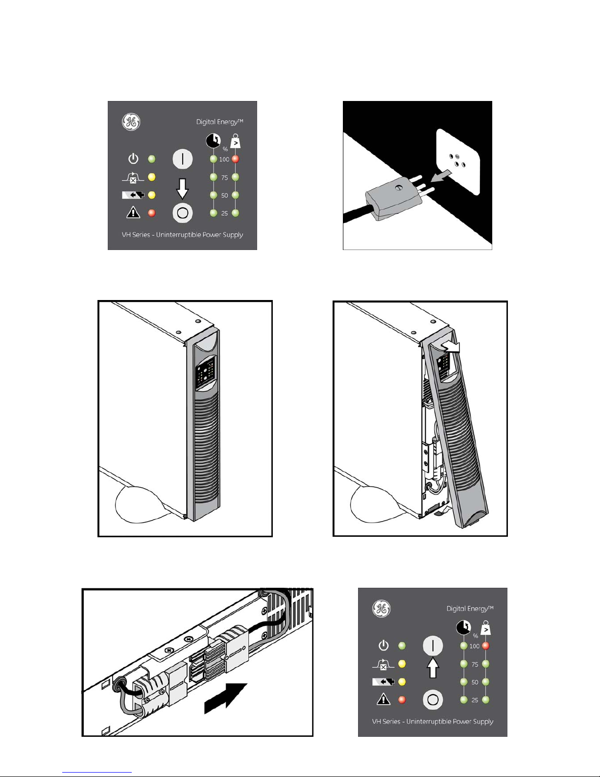
3 Switching off and unplug the battery
• 1 Press keypad ‘O’ for 1 second to switch off the UPS then disconnect the mains cable.
• 2 Pull out the lower part of the front panel to remove it.
• 3 Disconnect the DC connector of the internal batteries, then press the keypad ‘I ’ to discharge the capacitors.
Modifications reserved 4 ISG_VHS_FRM_UPD_XGB_V010.doc
Page 5
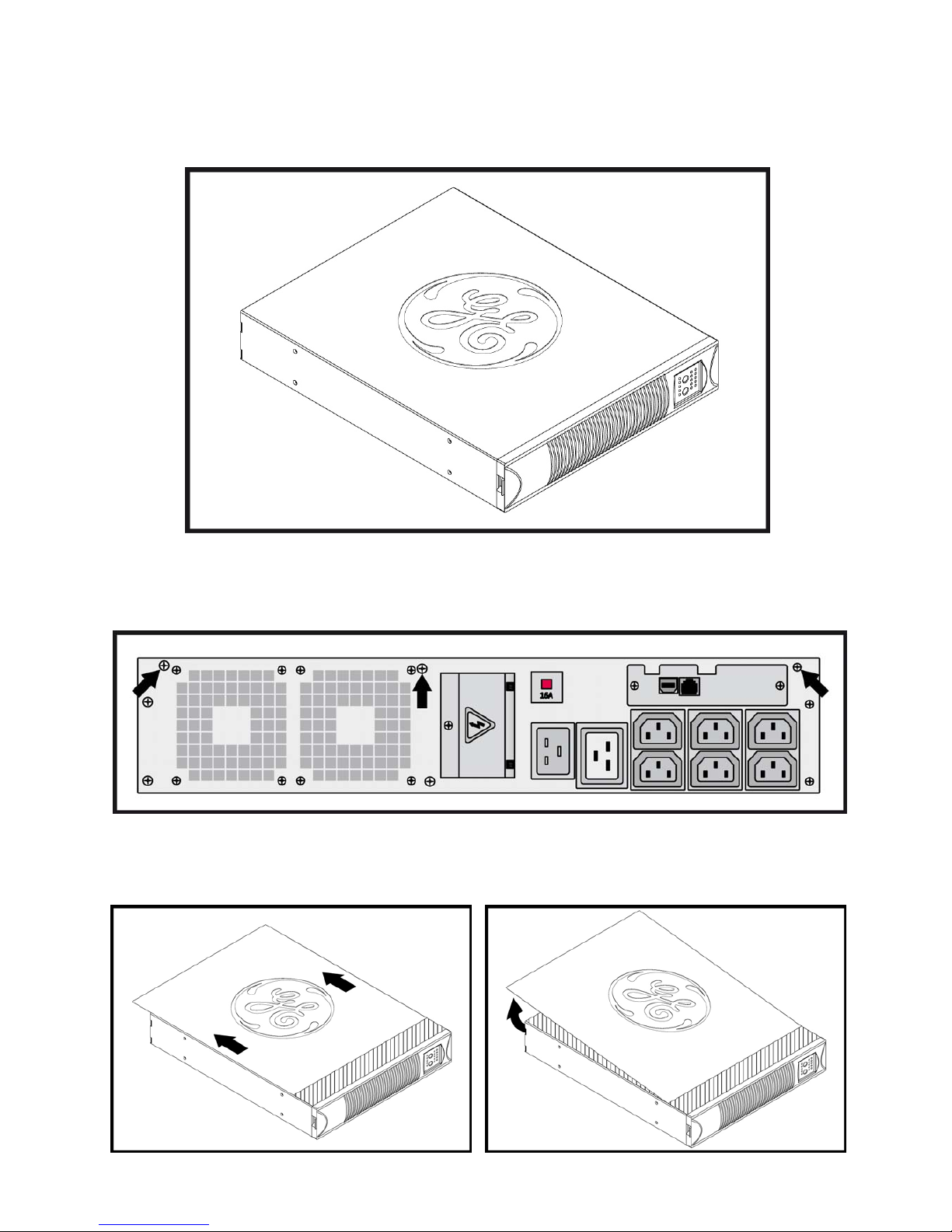
4 Remove top cover of the UPS
• 1 Place the UPS horizontally on a table or desk.
• 2 Remove the 3 screws how indicated on the picture.
• 3 Slide out the cover in the indicated direction and Pull up the cover to remove it from the UPS.
Modifications reserved 5 ISG_VHS_FRM_UPD_XGB_V010.doc
Page 6

5 Remove dangerous voltage
CAUTION
To avoid damage due to ESD (ElectroStatic Discharge) be sure that maintenance work is
performed under ESD-safe conditions: work on an anti-static mat; ground yourself and the unit
when it is opened.
CAUTION
When the UPS is uncovered use the proper caution to not damage the board and all the
electrical parts.
• 1 Wait 10 Minutes to allow discharge of the DC-Capacitors.
Put a multimeter on the 2 indicated points to check if the capacitor is discharged.
(remaining voltage has to be less than <20V)
Use a 100 Ohm / 10 Watt resistor to discharge the capacitor on the correct indicated points how
shown in the picture.
Modifications reserved 6 ISG_VHS_FRM_UPD_XGB_V010.doc
Page 7

• 2 Procedure:
•
Shut the UPS
down by pressing key ‘0’ on the Operating panel.
•
Remove Mains
voltage from the input socket.
•
Remove the Front Panel
and
disconnect the Battery plug.
•
Wait 10 Minutes to
allow discharge of the DC-Capacitors.
•
Remove dangerous voltage
and then
remove the UPS cover
, following instructions on page 5.
•
Measure the voltage across R316/R345* and R317/R346*.
( < 20 Volt )
*(For
VH700-VH1500
measure voltage on resistor
R345/R346
, and for
VH2000/VH3000
on
R316/R317
)
Modifications reserved 7 ISG_VHS_FRM_UPD_XGB_V010.doc
Page 8

6 Unplug the control board
• 1 Remove the 3 cables and the small board how indicated on the picture.
• 2 Remove the 2 screws that keep the lock tab for the control board.
• 3 Slide up the control board out of the VH cabinet.
Modifications reserved 8 ISG_VHS_FRM_UPD_XGB_V010.doc
Page 9

7 Programmer plug-in
Top view of the VH Prog. Board Top view of the E8a Programmer
Top view of the IM0128A5 Board
• 1 Insert the J1 connector of the VH Prog. Board in mid-position of J4 connector of the IM0128A5.
NOTE
: Pay attention that J1 pins are correctly fixed on J4 connector.
Fig. 1
Modifications reserved 9 ISG_VHS_FRM_UPD_XGB_V010.doc
Page 10

• 2 Insert the flat cable on J2 connector of the VH Prog. Board.
Fig. 2
• 3 Connect USB and the flat cable to the E8a Programmer.
Fig. 3
• 4 Top view of the final cabling for the firmware update with the VH Programming Board for
Digital Energy™ VH Series.
NOTE
: Pins 13 and 14 are 5V plug-in, and pins 15 and 16 are GND plug-in.
Fig. 4
Modifications reserved 10 ISG_VHS_FRM_UPD_XGB_V010.doc
Page 11

8 Firmware update
• 1 Download and Install HEW tool from renesas homepage (if not already installed).
Open the folder where you placed the Software Update.
Double click on the File named: VHSeriesV6RX.hws (Where X is the firmware version).
HEW tool will automatically open.
• 2 Configure settings in popup screen as follows:
• 3 After pressing the OK button, confirm 20 MHz selection and the Firmware will automatically be uploaded.
Modifications reserved 11 ISG_VHS_FRM_UPD_XGB_V010.doc
Page 12

• 4 Confirm Upload by pressing OK buttons.
• 5 Then Disconnect if you desire to program more than one Unit or exit if programming procedure is
finished.
• 6 Once that the UPS has been replaced and E8a is connected to the new Control board, connect again by
pressing Connect button (as shown in following picture) and restart from point 1.
Modifications reserved 12 ISG_VHS_FRM_UPD_XGB_V010.doc
Page 13

9 Testing and closing
• 1 Run UPS Configuration tool to check if the new firmware it is correctly installed.
• 2 Slide in the control board into the VH cabinet.
Modifications reserved 13 ISG_VHS_FRM_UPD_XGB_V010.doc
Page 14

• 3 Lock the 2 screws that keep the lock tab for the control board.
• 4 Reconnect the 3 cables and the small board on the control board how indicated in the picture.
• 5 Put the cover on the VH cabinet and Slide in the cover on the indicated direction.
Modifications reserved 14 ISG_VHS_FRM_UPD_XGB_V010.doc
Page 15

• 6 Lock the 3 screws how indicated on the picture.
• 7 Reconnect the DC connector of the internal batteries.
• 8 Pull in the lower part of the front panel to cover it.
• 9 The UPS it is now ready to operate.
Modifications reserved 15 ISG_VHS_FRM_UPD_XGB_V010.doc
Page 16

GE imagination at work
GE Consumer & Industrial SA
General Electric Company
CH – 6595 Riazzino (Locarno)
Switzerland
T +41 (0)91 / 850 51 51
F +41 (0)91 / 850 51 44
www.gedigitalenergy.com
Modifications reserved 16 ISG_VHS_FRM_UPD_XGB_V010.doc
 Loading...