

Page 1
Use this product only after carefully reading this manual and
understanding the contents.
Keep this manual close to the display.
Confirmity according to the Council Directive 93/42/EEC concerning
Medical Devices.
MODEL NO. 1926A-1AN
Resistive - Touch
Technical MANUAL
19 Inch Color LCD
Page 2

1. Revision History
•••••••••••••••••••••••••••••••••••••••
2. Equipment Symbols
••••••••••••••••••••••••••••••••••
3. Safety Precautions
•••••••••••••••••••••••••••••••••••
4. EMC Table
•••••••••••••••••••••••••••••••••••••••••••••
5. Connection Method
•••••••••••••••••••••••••••••••••••
6. Adjustment Method
•••••••••••••••••••••••••••••••••••
7. Compatible Signals
•••••••••••••••••••••••••••••••••••
8. Specifications
•••••••••••••••••••••••••••••••••••••••••
9. Cleaning Instruction
••••••••••••••••••••••••••••••••••
10. FCC Information
•••••••••••••••••••••••••••••••••••••
TABLE OF CONTENTS
1
2
6
9
15
19
28
31
32
33
Page 3

Revision Comment
1 Initial release of this document
The revision changes with related comments each time the document is updated.
RMF NO.: DOC1765836
1
Revision History
Page 4

Electrical and electronic equipment symbols
Alternating current.
Atmospheric pressure limitations.
p
u
European Union Declaration of Conformity.
FCC. USA only. Complies with applicable US government
(Federal Communications Commission) radio-frequency
interference regulations.
Indicates front.
Fragile. Handle with care.
i
FRONT
w
v
Humidity limitations.
Keep dry. Protect from rain.
y
p
Date of manufacture. This symbol indicates the date of manufacture
of this device. The first four digits identify the year, the following two
digits identify the month, and the last two digits identify the day.
Eurasian Economic Union countries only. Eurasian Conformity
mark. Conformity to applicable technical regulations of
Customs Union.
2
Equipment Symbols
Page 5
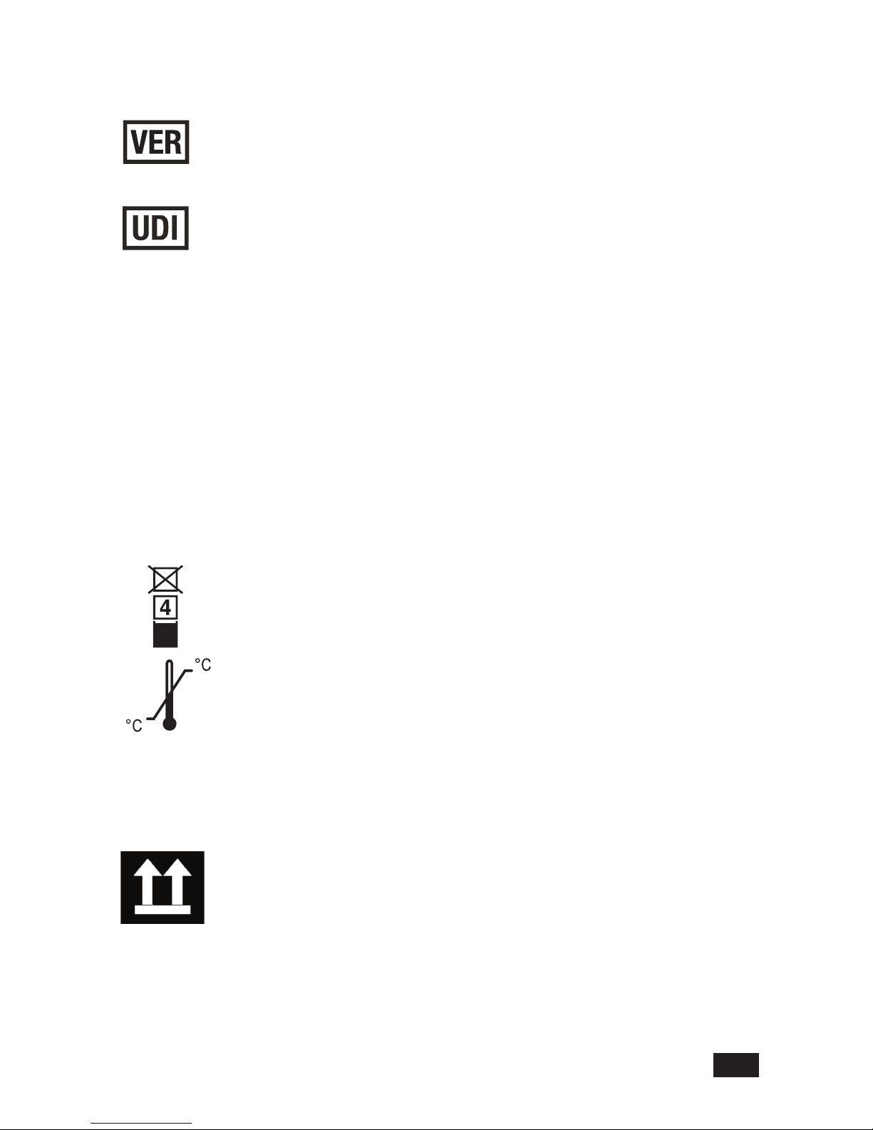
Recycled materials or may be recycled.
Device serial number.
Stacking limit by number.
Temperature limitations.
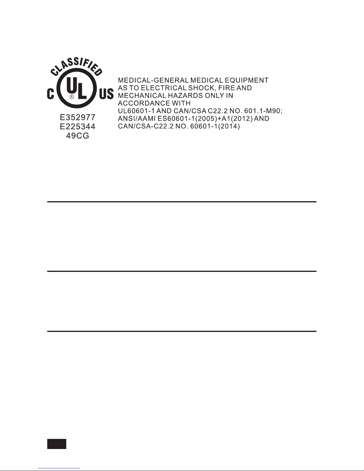
Underwriters Laboratories product certication mark.
Catalogue or orderable part number.
6
[
7
e
This way up.
Device hardware version.
Every device has a unique marking for identification.
The UDI marking appears on the device label
3
Page 6

This symbol indicates that the waste of electrical and electronic equipment
must not be disposed a s u n sorted m u n i cipal w a s t e and mus t b e
collected separately. Please contact an authorized representative of the
manufacturer for information concerning the decommissioning of your
equipment
k
h
g
f
The LCD display complies with the China Compulsory Certification
(GB4943.1-2001, GB9254-2008, GB17625 1-2012). CCC China only.
NOTE: The following symbols (required by China law only) are
representative of what you may see on your equipment. The number
in the symbol indicates the EFUP period in years, as explained below.
Check the symbol on your equipment for its EFUP period.This symbol
indicates the product contains hazardous materials in excess of the
limits established by the Chinese standard (January 2016): GB/T
26572 Requirements for Concentration Limits for Certain Hazardous
Substances in Electronic Information Products. The number in the
symbol is the Environment-friendly User Period (EFUP), which indicates
the period during which the hazardous substances or elements
contained in electronic information products will not leak or mutate under
normal operating conditions so that the use of such electronic information
products will not result in any severe environmental pollution, any bodily
injury or damage to any assets. The unit of the period is “Year”. In order
to maintain the declared EFUP, the product shall be operated normally
according to the instructions and environmental conditions as dened in
the product manual, and periodic maintenance schedules specified in
Product Maintenance Procedures shall be followed strictly. Consumables
or certain parts may have their own label with an EFUP value less
than the product. Periodic replacement of those consumables or parts
to maintain the declared EFUP shall be done in accordance with the
Product Maintenance Procedures. This product must not be disposed
of as unsorted municipal waste, and must be collected separately and
handled properly after decommissioning.
4
Page 7
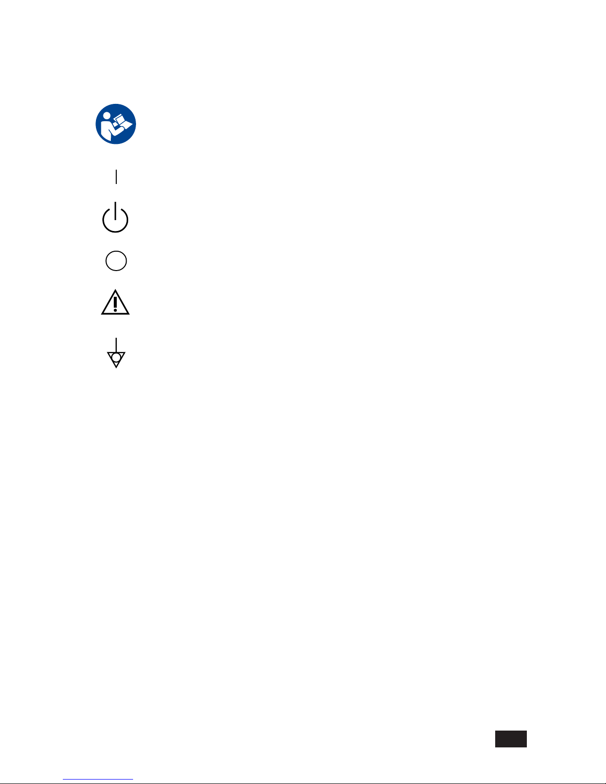
ON. Power connection to the mains.
Follow instructions for use.
Standby or power indicator.
ATTENTION: Consult accompanying documents.
Power OFF.
Equipotentiality. Connect device to a potential equalization conductor.
5
Page 8

6
●
Make sure to carefully read the User Manual that accompanies the patient display prior
to using this display to ensure proper operation of the devices.
●
Note that, excluding those cases where a responsibility for legal compensation is
recognized, the manufacturer shall bear absolutely no responsibility for damage to this
product by a customer or a third party that results in improper use from the ignoring of the
contents entered in this Technical Manual.
●
Follow the instructions below for safe use of the LCD Display.
- To avoid electric shock, do not attempt to remove any cover or touch the inside of the
LCD Display. Only a qualied service technician should open the LCD Display case.
- Do not insert metal objects or spill liquid into the LCD Display through cabinet slots.
They may cause accidental fire, electric shock or failure. In case a foreign object was
inserted or water has penetrated, unplug the AC cable and have the LCD Display serviced.
- Do not cover or block the vent holes in the case.
- Disconnect the power plug from the AC outlet if you will not use it for an indenite period
of time.
- Do not apply pressure to the screen. The LCD Display is very delicate.
● No modification of this equipment is allowed. Safe use of the equipment cannot be
guaranteed if unauthorized modications are made to the display.
● If this equipment is modied, appropriate inspection and testing must be conducted to
ensure continued safe use of the equipment.
● OPERATOR must not touch the enclosure and PATIENT simultaneously.
● Do not connect to multiple socket outlets.
● To avoid the risk of electric shock this equipment must only be connected to a supply
mains with protective earth.
●
If your LCD Display uses an AC/DC Adapter: Only use the Adapter, which accompanied
this device. Use of another AC/DC Adapter may cause a malfunction or electrical shock
or re hazard.
●
If your LCD Display does not operate normally. In particular, if there are any unusual
sounds or smells coming from it-unplug the AC cable immediately and contact the
manufacturer, or authorized service center.
Safety Precautions
Page 9

7
●
POWER SUPPLY. The device must be connected to a properly installed power outlet
with protective earth contacts only. If the integrity of the protective earth conductors is in
doubt, disconnect the LCD Display from the power line and use it with the battery option if
available). If the installation does not provide for a protective earth conductor, disconnect
the LCD Display from the power line. All devices in a system must be connected to the
same power supply circuit. Devices which are not connected to the same circuit must be
electrically isolated when operated.
●
GE is responsible for the effects on safety, readability, and performance of the equipment
only if:
-
Assembly operations, extensions, readjustments, modications, servicing, or repairs are
carried out by authorized service personnel.
-
The electrical installation of the relevant room complies with the requirements of the
appropriate regulations.
-
The equipment is used in accordance with the instructions for use of the patient display
and this Technical manual.
●
Grounding reliability can only be achieved when the equipment is connected to an
equivalent receptacle marked “Hospital Only” or “Hospital Grade”.
●
DO NOT position the LCD Display so that it is difficult to operate or to connect and
disconnect the AC power cord.
●DO NOT touch the patient simultaneously with connection or disconnection of cables.
●Installation and OSD adjusting should only be carried by manufacturer trained and
authorized personnel.
Page 10
I
CLASSIFICATION
II
External Equipment
External equipment intended for connection to signal input / output or other connectors, shall
comply with IEC 60601-1 for medical electrical equipment. In addition, all such combination
systems shall comply with the standard IEC 60601-1-1, Safety requirements for medical electrical
systems. Equipment not complying with IEC 60601-1 shall be kept outside the patient
environment, as dened in the systems standard.
III
Intended Use
Class I :
No applied parts
Protection against harmful ingress of water is IPX1
Not suitable for use in the presence of ammable anesthetics or oxygen.
Mode of operation: Continuous.
8
The single device output analog signals through ADC element (Analog Digital Convert)
conversion to become a digital signal and the video signal is via Video Decorder
conversion. I t has become the same digital signal, these signals via Scaler IC as zoom
in or out action and digital image processing, then through the cable line transmission
LVDS signals to one of the LCD module. The last by the clock controller (Timing Controller,
TCON), the clock signal is transmitted to the drive IC on the panel and turn on Backlight for
LCD module light source by Scaler control.
The equipment is intended to be used as a component of a medical patient monitoring
system for infant or adults by professional physician. The display shall be classified as
NON-LIFE SUPPORTING.
IV
Operating Principle
Page 11
EMC Table
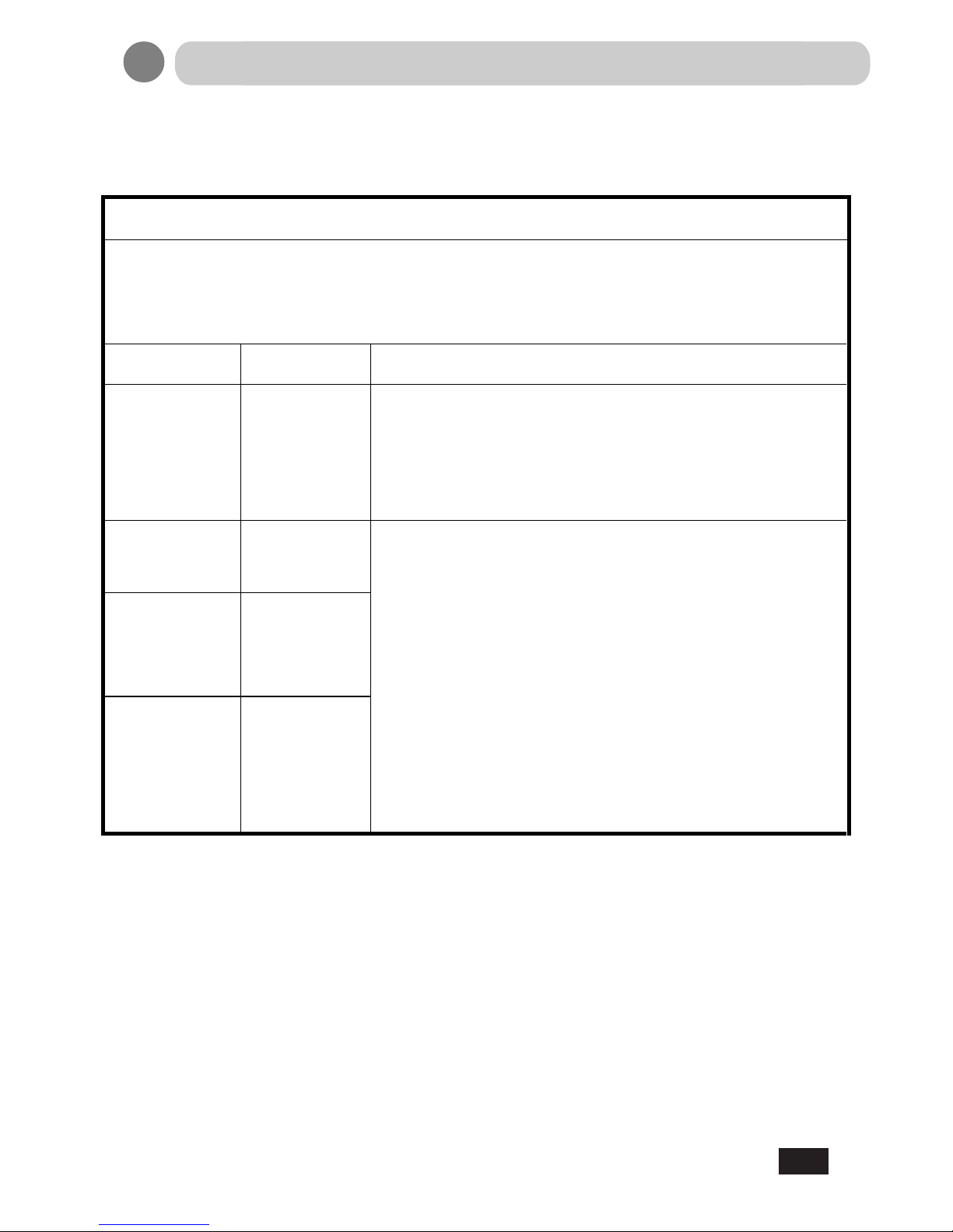
Guidance and manufacturer’s declaration-electromagnetic immunity for all
EQUIPMENT AND SYSTEMS
Guidance and manufacturer’s declaration-electromagnetic emissions
The LCD display for Healthcare Applications is intended for use in the electromagnetic
environment specified below. The customer or the user of the LCD display for Healthcare
Applications should assure that it is used in such an environment.
Emissions test Compliance Electromagnetic environment-guidelines
RF emissions
CISPR 11
Group 1
The LCD display for Healthcare Applications uses RF
energy only for its internal function. Therefore, its RF emissions
are very low and are not likely to cause any interference in nearby
electronic equipment.
RF emissions
CISPR 11
Class A
The LCD display for Healthcare Applications is suitable
for use in all establishments other than domestic and
those directly connected to a low voltage power supply network
which supplies buildings used for domestic purposes.
Harmonics
emissions
IEC 61000-3-2
Class D
Voltage
fluctuations/flicker
emissions
IEC 61000-3-3
Complies
9
EMC Table
Page 12
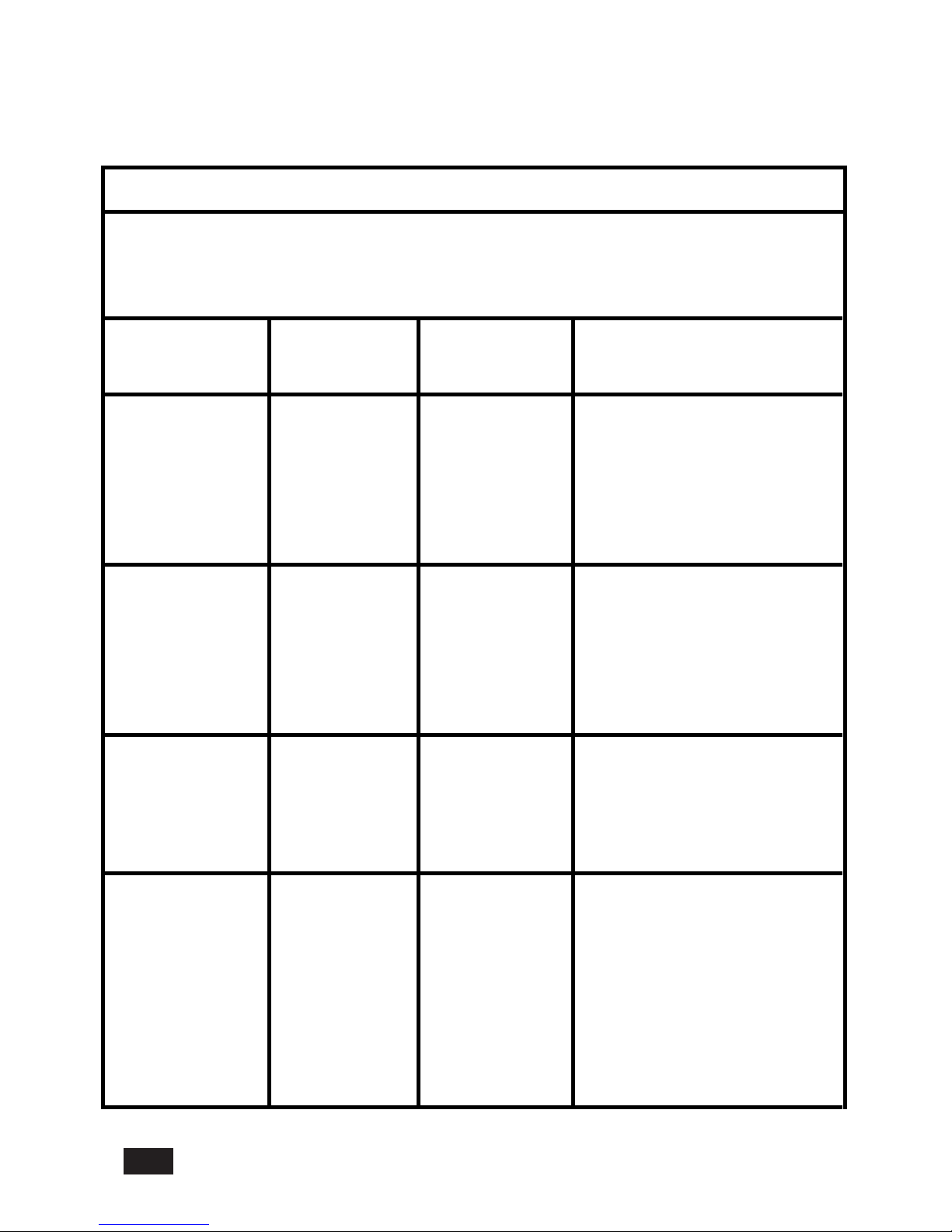
Guidance and manufacturer’s declaration-electromagnetic immunity for all EQUIPMENT
AND SYSTEMS
Guidance and manufacturer’s declaration-electromagnetic immunity
The LCD display for Healthcare Applications is intended for use in the
electromagnetic environment specified below. The customer, or the user of the LCD display for
Healthcare Applications, should assure that it is used in such an environment.
Immunity Test
Level
IEC 60601 Compliance Level Electromagnetic Environment -
Guidelines
Electrostatic
Discharge (ESD)
IEC 61000-4-2
± 8 kV contact
± 15 kV air
± 8 kV contact
± 15 kV air
Floors should be wood, concrete
or ceramic tile. If floors are
covered with synthetic material,
the relative humidity should be at
least 30%.
Electrical Fast
Transient/Burst
IEC 61000-4-4
± 2 kV for power
supply lines
± 1 kV for
input/output lines
± 2 kV for power
supply lines
± 1 kV for
input/output
Lines
Mains power quality should be
that of a typical commercial or
hospital environment.
Surge
IEC 61000-4-5
± 1 kVline(s) to
line(s)
± 2 kV line(s) to
earth
±1kVline(s)to
line(s)
± 2 kV line(s) to
earth
Mains power quality should be
that of a typical commercial or
hospital environment.
Voltage Dips, Short
Interruption and
Voltage Variations
on Power Supply
Input Lines
IEC 61000-4-11
<5% UT
(>95% dip in UT)
for 0.5 cycle
40% UT
(60% dip in UT)
for 5 cycles
70% UT
<5% UT
(>95% dip in UT)
for 0.5 cycle
40% UT
(60 % dip in UT)
for 5 cycles
70% UT
Mains power quality should be
that of a typical commercial or
hospital environment.
If the user of the LCD display for
Healthcare Applications requires
continued operation during power
mains interruptions, It is
10
Page 13
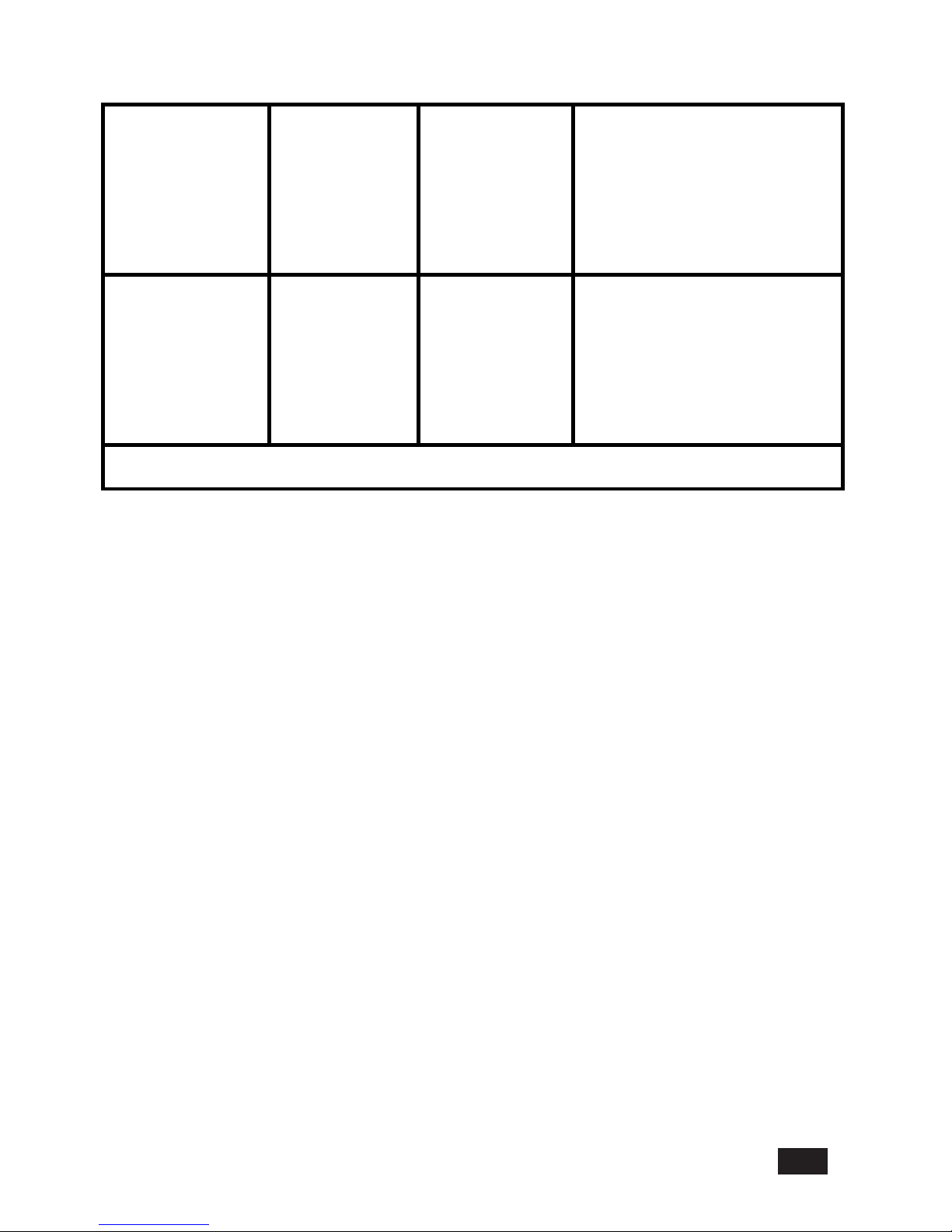
(30% dip in UT)
for 25 cycles
<5% UT
(>95% dip in UT)
for 250 cycles
(30% dip in UT)
for 25 cycles
<5% UT
(>95% dip in UT)
for 250 cycles
recommended that the LCD
display for Healthcare
Applications be powered from an
uninterruptible power supply or a
battery.
Power Frequency
(50/60 Hz)
Magnetic Field
IEC 61000-4-8
3 A/m 3 A/m Power frequency magnetic fields
should be at levels characteristic
of a typical location in a typical
commercial or hospital
environment.
NOTE UT is the A.C. mains voltage prior to application of the test level.
11
Page 14
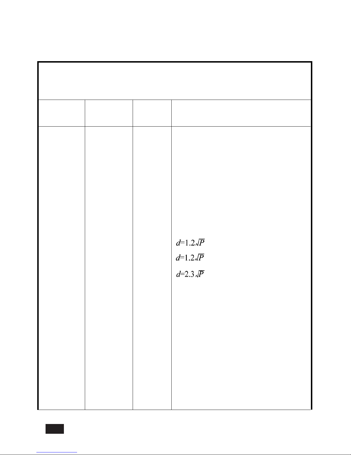
Guidance and manufacturer’s declaration-electromagnetic immunity for all EQUIPMENT
AND SYSTEMS that are not LIFE-SUPPORTING
The LCD display for Healthcare Applications is intended for use in the electromagnetic
environment specified below. The user of the LCD display for Healthcare Applications should
assure that it is used in such an environment.
Immunity Test IEC 60601 Test
Level
Compliance
Level
Electromagnetic Environment-Guidelines
Conducted RF
Radiated RF
IEC 61000-4-3
3 Vrms
3 V/m
80 MHz to 2.5
GHz
3 Vrms
3 Vrms
Portable and mobile RF communications
equipment should be used no closer to any part
of the LCD display for Healthcare Applications
and should assure that it is used in such an
environment, including cables, than the
recommended separation distance calculated
from the equation applicabl
e to the frequency of
the transmitter. Recommended separation
distance
80MHz to 800 MHz
800 MHz to 2.5GHz
where P is the maximum output power rating of
the transmitter in watts (W) according to the
Field strengths from fixed RF transmitters, as
determined by an electromagnetic site survey*1,
should be less than the compliance level in
each frequency range*2.
Interference may occur in the vicinity of
equipment marked with the following symbol:
12
transmitter manufacturer and d is the
recommended separation distance in metres(m)
Page 15
* 1: At 80 MHz and 800 MHz, the higher frequency range applies.
* 2: These guidelines may not apply in all situations. Electromagnetic propagation is
affected by absorption and reflection from structures, objects and people.
1.Field strengths from fixed transmitters, such as base stations for radio (cellular/cordless)
telephones and land mobile radios, amateur radio, AM and FM radio broadcast and TV
broadcast cannot be predicted theoretically with accuracy. To assess the elec
tromagnetic
environment due to fixed RF transmitters, an electromagnetic site survey should be
considered. If the measured field strength in the location in which the LCD display for
Healthcare Applications is used exceeds the applicable RF compliance leve
l above, the LCD
display for Healthcare Applications should be observed to verify normal operation. If abnormal
performance is observed, additional measures may be n ecessary, such as reorienting or
relocating the LCD display for Healthcare Applications.
2.Over the frequency range 150 kHz to 80 MHz, field strengths should be less than 3 Vrms.
13
Page 16
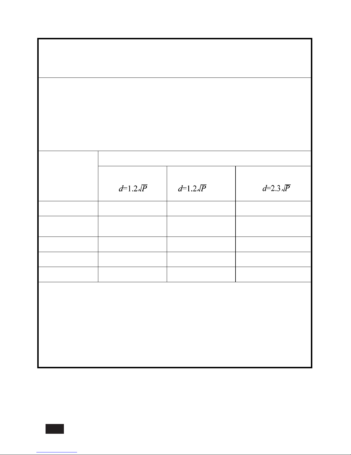
Recommended separation distances between portable and mobile RF communications
equipment and the LCD display for Healthcare Applications for all EQUIPTMENT AND
SYSTEMS that are not LIFE-SUPPORTING
The LCD display for Healthcare Applications is intended for use in an electromagnetic
environment in which radiated RF disturbances are controlled. The customer or the user of the
LCD display for Healthcare Applications can help prevent electromagnetic interference by
maintaining a minimum distance between portable and mobile RF communications
(equipment) and the LCD display for Healthcare Applications as recommended below
according to the maximum output power of the communications equipment.
Rated Maximum
Output Power of
Transmitter
(W)
Separation Distance According to Frequency of Transmitter
150 kHz to 80 MHz 80MHzto800MHz 800MHz to 2.5 GHz
0.01
0.12 0.12 0.23
0.1 0.37 0.37 0.74
1 1.2 1.2 2.3
10 3.7 3.7 7.4
100 12 12 23
For transmitters rated at a maximum output power not listed above, the recommended separation
distanced in metres (m) can be estimated using the equation applicable to the frequency of the
transmitter, where P is the maximum output po
wer rating of the transmitter in watts (W) according to the
transmitter manufacturer.
14
Page 17
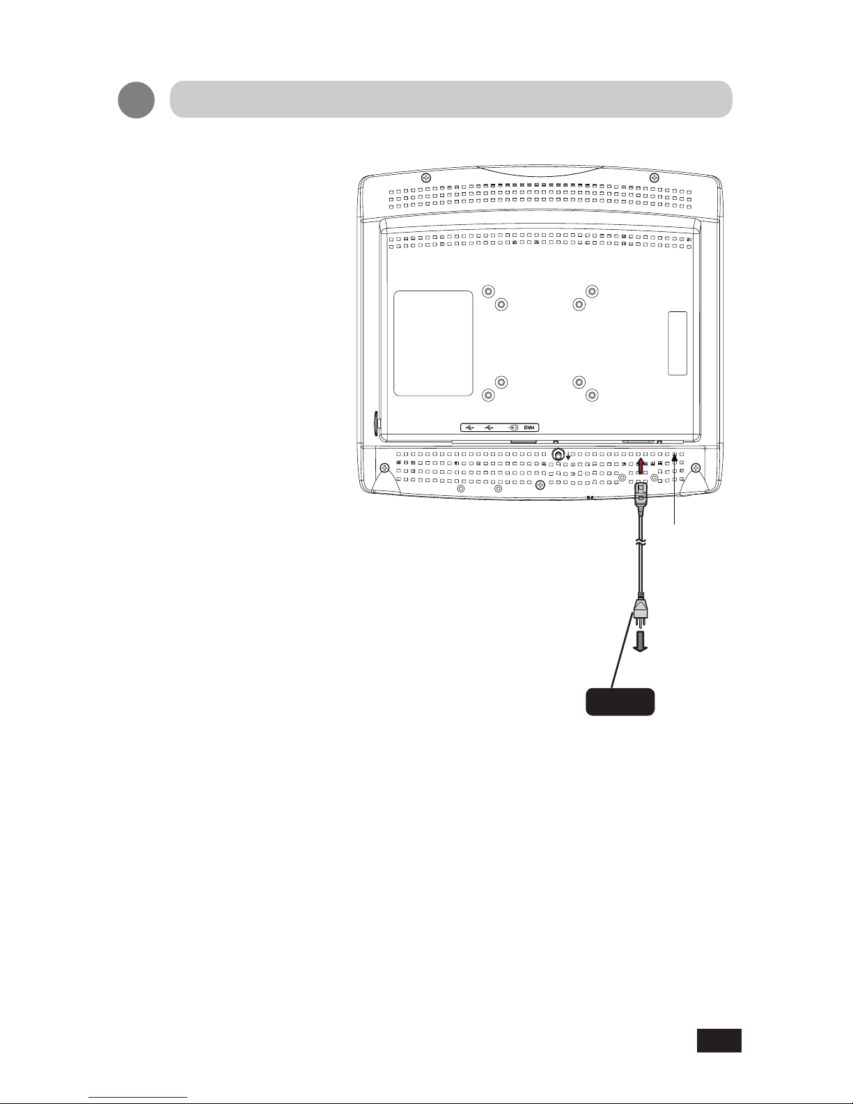
1.
Connect the AC power cord
provided into the display's power
input. Then, connect the plug
into an outlet.
Note
When connecting the AC power
cable, do not forget to install the
cable supplied in the accessory
box.
Connection Method
Power cord
(Accessory)
Main Power
Supply Switch
To power outlet
15
Page 18
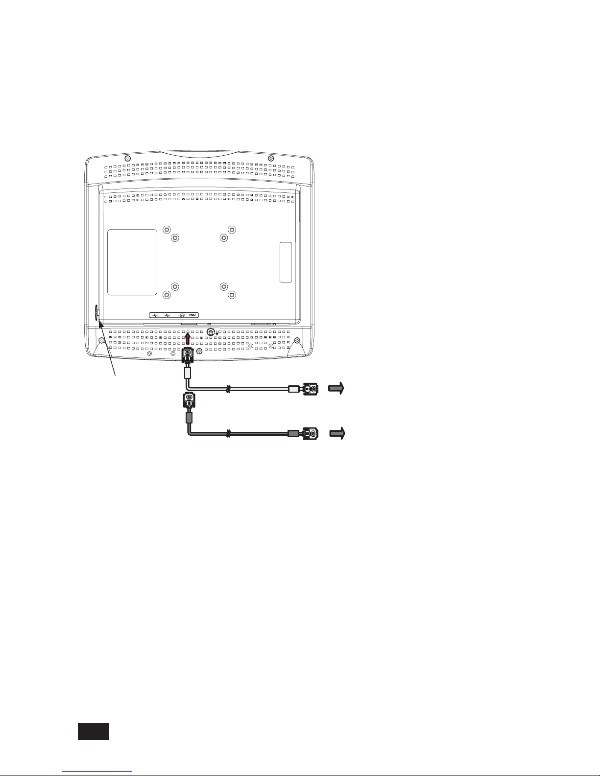
3
.Connect the signal cable (for SYSTEM input).
Connect the DVI-I connector of the display and the digital output of the system with the provided
DVI-D to DVI-D cable. Do not forget to tighten the screws of the cable. The display is shipped
with the default input selected to DVI-D. The user can also select the DVI-A option if necessary.
If the NO SYNC message appears, the wrong input signal is selected. Please check the video
input and change the source input. See Page 23 for details (OSD Source Select Menu).
Use the display's DVI-I connector to make this connection. Do not forget to tighten the
screws of the cable. See Page 23 for details (OSD Source Select Menu).
Digital output of SYSTEM
Analog output of SYSTEM
OSD knob
16
Page 19
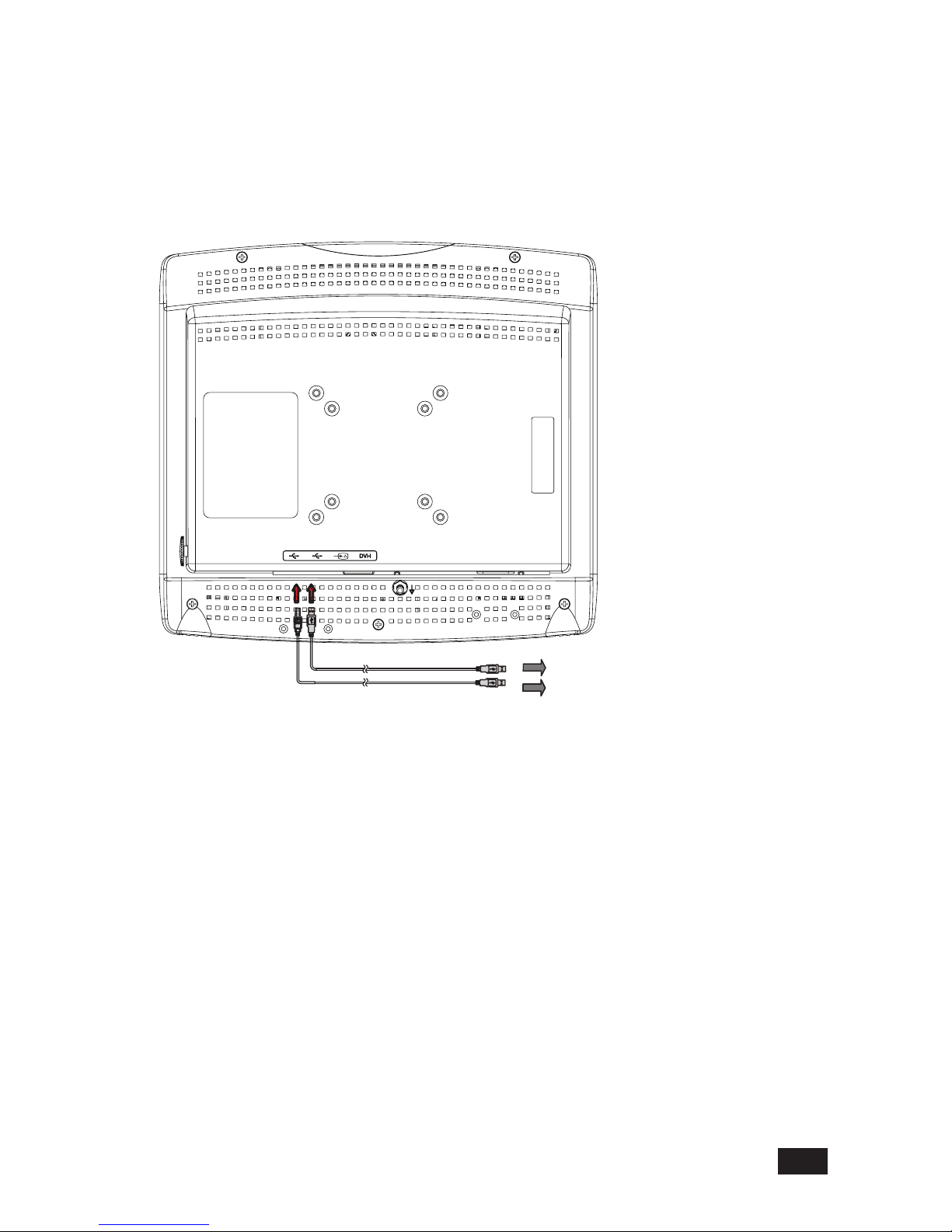
4.
Connect USB Cable.
Connect the system's USB TYPE A port and the displays USB TYPE B port with the
provided USB cable.
Downstream ports shall be used for accessories such as a mouse, keyboard, barcode
scanner or a remote input device. Such accessories are permitted to be connected directly
to the USB downstream port of this display.
Note:
When connecting the USB Cables do not forget to install the USB Cable Holder, as supplied in
the accessory box.
To USB Downstream port TYPE A
To USB Upstream port TYPE B
17
Page 20
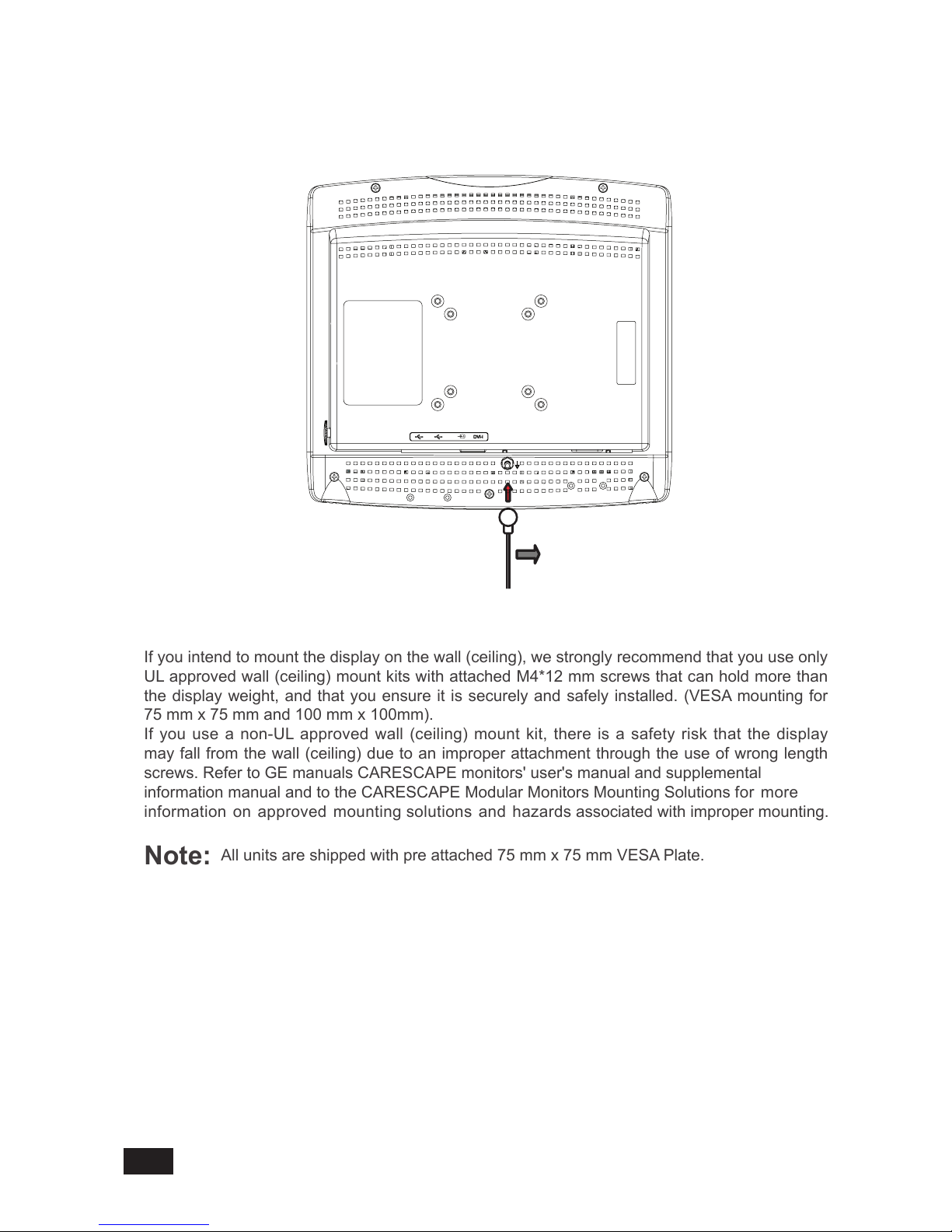
5. Potential Equalization Connector
If you intend to mount the display on the wall (ceiling), we strongly recommend that you use only
UL approved wall (ceiling) mount kits with attached M4*12 mm screws that can hold more than
the display weight, and that you ensure it is securely and safely installed. (VESA mounting for
75 mm x 75 mm and 100 mm x 100mm).
If you use a non-UL approved wall (ceiling) mount kit, there is a safety risk that the display
may fall from the wall (ceiling) due to an improper attachment through the use of wrong length
screws. Refer to GE manuals CARESCAPE monitors' user's manual and supplemental
information manual and to the CARESCAPE Modular Monitors Mounting Solutions for more
information on approved mounting solutions and hazards associated with improper mounting.
Note:
All units are shipped with pre attached 75 mm x 75 mm VESA Plate.
Display is equipped with an equipotential connector.
6. Wall (Ceiling) VESA mounting the display.
Equipotential cable
18
Page 21
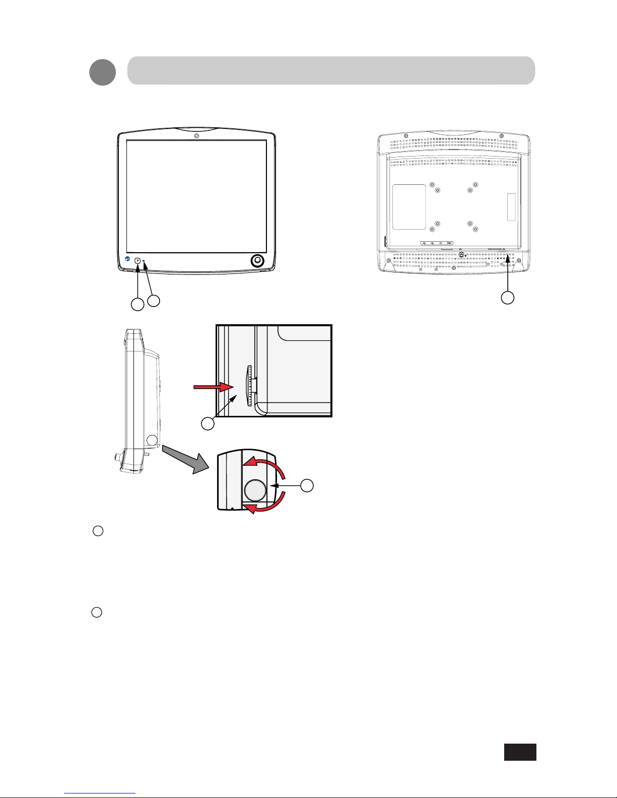
1.0 Names and Function of Each Section
2
2
1
Power Switch Button (Power ON/OFF)
2
On Screen Display (OSD) Control
•
Pressing the power button for more than one second, and then releasing, turns on the
color LCD display. Pressing the same button again turns the display off. The display shall
recall the On/Off status even if the external power source is removed.
•
When the OSD control dial is pressed while the display is on, the OSD display window
appears on screen.
• OSD stands for On Screen Display. Its function is to display information for conguring
the display. The OSD display window cannot be activated if the display is presently
displaying an error message such as "NO SYNC". The user must wait for the message to
extinguish. Error messages are self-generated by the display and indicate invalid video
input conditions.
Adjustment Method
4
3
1
19
Page 22

•
When the OSD is displayed, execution of selected items and display of submenus can
be performed.
• Control dial functions are as follows:
Rotate clockwise or counterclockwise: up-and-down movement / left-and-right
movement / increasing and decreasing etc.
Press the control dial inward briey and then release to: execute / select items / save
data.
3
4
Power Indicator
•
The indicator illuminates green when power is normally on.
• The indicator goes out when power is off.
The AC main power supply switch interrupts the AC input to the display. Placing the switch
in the ON( | ) position allows display to power-up, if the AC input is connected.
Placing the switch in the OFF( O ) position shall cause the display to power down if
powered by AC input.
AC Main Power Supply Switch
20
Page 23

The OSD menu is displayed with lcons, adjustment items, and setting values as shown below.
The gure below is the main menu.
OSD adjustment screen has "main menu" and "sub menus".
MAIN M E N U
Exit
Auto Setup
Brightness
Contrast
Clock / Phase
Display
Management
Auto Setup
Adjustment item Icons
lcons of adjustable items
Cursor display
Rotati n g the OSD c o n t ro l dia l ,
scr o lls th e curs o r th ro ugh th e
lis t of item s , and dis p l ays it as
"highlighted".
Message windows
Shows information about the
highlighted icon.
2.0 OSD Adjustments
This section shows how to make adjustments to the LCD screen that is displaying a valid video
input. Operating the control dial on the back of the display enables the user to make settings and
adjustments for the selected items. See Drawing on page 19 item number (2) for location of the
OSD Control dial.
OSD display
Adjustable items and setting values are
shown on screen. OSD stands for onscreen-display. Its function is to display
information for conguring the display.
Thi s OS D is no r ma ll y disp l ay ed in
the center of the screen, but its exact
location can be moved. However the size
of the OSD display can not be changed.
Notes
MAIN M E N U
Exit
Auto Setup
Brightness
Contrast
Clock / Phase
Display
Management
Auto Setup
2.1 OSD Display
21
Page 24

Adjustment examples from the main menu below.
e.g.,"Brightness" adjustment
Adjustment 1...from the main menu
1.Press the control dial and display the OSD
menu (See Fig.1).
2.Rotate the dial to select "Brightness" and press
the dial (See Fig.2).
("Brightness" display will appear) (See Fig.3).
3.Rotate the dial to make Brightness adjustments
(See Fig.4).
Adjustable within the range from 0 to 100
4.Press the dial to nish adjustments (return to
Fig.1).
5.Rotate the dial to select "Exit". Press Control dial
to close the OSD main menu.
Fig.1 Main menu
Fig. 2 Select "Brightness"
Fig. 3 "Brightness" display
Fig. 4 "Brightness" adjustment
Brightness
- +
90
Brightness
- +
100
MAIN M E N U
Exit
Auto Setup
Brightness
Contrast
Clock / Phase
Display
Management
: Enter
: +/-
DVI-I Analog
MAIN M E N U
Exit
Auto Setup
Brightness
Contrast
Clock / Phase
Display
Management
9090
2.2 How to Operate
22
Page 25

During power up after first configuring your
display, the display may show the NO SYNC
message ( See figure 1). This may be due to
the wrong source input "saved" in the display.
The display does not auto-select source inputs.
To change the display's source input see below.
gure 1
gure 2
2.3 OSD Source Select Menu
Briefly press in the OSD Control dial. The
OSD shall display the Source Select Menu.
See gure 2.
Rotate the OSD Control dial to select the
desired source input. In the case of figure 3,
DVI-I digital has been selected. Then briefly
press in the OSD Control dial to save and
execute your selection.
gure 3
23
Page 26

2.4 OSD adjustment function
●
OSD adjustment function
The OSD hierarchy and functions are outlined below.
Main menu display
• Auto Setup
• Brightness
• Contrast
• Clock/Phase
• Management
• Display
Auto Setup........Automatic screen size/position/freq./phase adjustment (Analog only).
Brightness.........Adjust the brightness of the full screen within the range of 0 to 100.
Contrast ...........Adjust the Contrast of the full screen within the range of 0 to 100.
Clock ......................Fine adjustment of on horizontal position of video input (Analog only).
OSD Display
H.Position........Adjust horizontal position of image (Analog Only).
V.Position.........Adjust vertical position of image (Analog Only).
Language
Source...................Selects between Analog and Digital when both inputs are applied.
Recall..............................Restores factory settings.
Exit..............................Return to main menu.
OSD H. Pos................Adjust horizontal position of OSD.
OSD V. Pos................Adjust vertical position of OSD.
DVI-I Analog
DVI-I Digital
Exit.....................Return to main menu.
Italiano................Display OSD in Italiano.
Francais..............Display OSD in Francais.
Espanol...............Display OSD in Espanol.
Deutsch...............Display OSD in Deutsch.
日本語
................Display OSD in Japanese.
OSD H. Pos................Adjust the OSD H. Pos of the full screen within
the range of 0 to 100.
OSD V. Pos................Adjust the OSD V. Pos of the full screen within
the range of 0 to 100.
Phase .....................ADC (analog to digital conversion) phase adjustments (Analog only).
English................Display OSD in English.
............Display OSD in Simplified Chinese.
24
Page 27

2.5 Details of Adjustment Items
Exit
Auto setup
Brightness
Contrast
Display
The adjustment functions are described as follows.
Close the OSD main menu.
Automatically adjusts the size, position and contrast of the screen. When rst using this
color display or inputting new timings, perform this adjustment.
Adjusts brightness of the screen. Increasing the value provides more brightness to the screen.
Adjustment is within the range of 0 to 100.
Adjusts contrast of the screen. Increasing the value provides more contrast to the screen.
Adjustment is within the range of 0 to 100.
Clock / Phase
When using the analog input make "Phase" adjustments, if any ickers, blurs, or horizontal
stripes show on the screen. Adjustment is within the range of 0 to 63. For the digital input
(DVI), this function is not available.
Phase (phase adjustment)
Adjusts the horizontal position of the display image. Adjustment range is 0 to 100
(Analog Only).
Adjusts the vertical position of the display image. Adjustment range is 0 to 100
(Analog Only).
V.Position
H.Position
25
Page 28

Management
Exit
•OSD H. Pos....................Adjust horizontal position of OSD
•
DVI-I Analog
•OSD V. Pos....................Adjust vertical position of OSD
•
DVI-I Digital
•OSD H. Pos....................Adjust the OSD H.Pos of the full screen within the range of
0 to 100
•OSD V. Pos...................Adjust the OSD V. Pos of the full screen within the range
of 0 to100
Make "Clock" adjustments whenever the "Auto-adjustment" does not adequately center the
screen. Rotating the control dial will adjust the position of the video display with respect to the
Horizontal Sync signal. Adjustment is within the range of 0 to 100. As the value gets larger,
the screen moves to the right, and vice versa. For the digital input (DVI), this function is not
available.
Select this control, then rotate the control dial to select the language you want. Press
the control dial to execute when selected.
Selects between Analog and Digital when both inputs are applied.
Restores factory settings.
Return to the main menu.
Close the OSD main menu.
OSD Display
Language
Source
Recall
Exit
Clock (clock adjustment)
26
Page 29

2.6 Brightness Only Control Display Window
The brightness only control is available whenever the other menus are not on the display. View
the brightness scale by rotating the OSD control dial. See the drawing on page 22 item number
(2).
2.7 OSD Error Messages
The OSD shall automatically display "Error Messages" when faults with the video input are
detected by the display unit. The messages are as described below.
NO SYNC
No video signal is present or wrong input source is "saved" in the dis
play ( See section 2.3).
No Support
Vertical refresh frequency of the input video signal is less than or greater than the values
specied in "Compatible Signals".
Out of Range
Horizontal refresh frequency is less than or greater than the values specied in "Compatible
Signals".
27
Page 30

1.0 Timing of Compatible Signals
The display may not work properly if the timings are other than those below.
Recommended timing — Not Supported
Display Mode H-Frequency V-Frequency Pixel Frequency Anaiog input Digital input
V
E
S
A
VGA
640 x 480
31.47kHz 60.00Hz 25.175MHz
37.50kHz 75.00Hz 31.50MHz —
37.86kHz 72.00Hz 31.50MHz —
SVGA
800 x 600
35.16kHz 56.25Hz 36.00MHz —
37.88kHz 60.00Hz 40.00MHz
48.08kHz 72.00Hz 50.00MHz —
46.88kHz 75.00Hz 49.00MHz —
XGA
1024 x 768
48.36kHz 60.00Hz 65.00MHz
56.48kHz 70.00Hz 75.00MHz —
60.02kHz 75.00Hz 78.00MHz —
SXGA
1280 x1024
63.98kHz 60.00Hz 108.00MHz
79.98kHz 75.00Hz 135.00MHz
—
VGATEXT
720 x 400
31.47kHz 70.00Hz 28.32MHz
1024 x 512 34.38kHz 60.00Hz 46.76MHz
640 x 350 31.47kHz 70.00Hz 28.32MHz —
Compatible Signals
28
Page 31

2.0 Arrangement of Connector Pins
Pin Number Signal Name
1 T.M.D.S Data2-
2 T.M.D.S Data2+
3 T.M.D.S Data2/4 Shield
4 NC
5 NC
6 DDC Clock
7 DDC Data
8 Analog Vertical sync
9 T.M.D.S Data110 T.M.D.S Data1+
11 T.M.D.S Data1/3 Shield
12 NC
13 NC
14 +5V Power
15 Ground
16 Hot Plug Detect
17 T.M.D.S Data018 T.M.D.S Data0+
19 T.M.D.S Data0/5 Shield
20 NC
21 NC
22 T.M.D.S Clock Shield
23 T.M.D.S Clock+
24 T.M.D.S Clock-
C1 Analog Red video out
C2 Analog Green video out
C3 Analog Blue video out
C4 Analog Horizontal sync
C5 Analog Common Ground Return
Pin Number Signal Name
1 VBUS
2 D 3 D +
4 GND
2. 4 pin USB-B TYPE Upstream Connector
29
Page 32

Pin Number Signal Name
1 VBUS
2 D 3 D +
4 GND
3. 4 pin USB-A TYPE Downstream Connector
30
Page 33

31
Specications
Items Specications
LCD display device 19 inch Color TFT Normally Black
Pixel pitch Horizontal 0.294mm x Vertical 0.294mm
Display area Horizontal 376.32mm x Vertical 301.06mm
Pixel 1280 x 1024 pixels
Display gradation 16.7 M colors (True)
Standard viewing
angle
Conditions
Min Max
Horizontal (Right)
75 89
CR=10 (Left)
75 89
Vertical (Up)
75 89
CR=10 (Down)
75 89
Input signal
(1) DVI-I (29-pin) Connector
(2) USB B Type connector:
compliant with USB 2.0
(3) USB A Type*2 connector:
compliant with USB 2.0
Environment
Operation Transport / Storage
Temperature
0~40°C -20~60°C
Humidity 10~90
% 10~90%
Air pressure
700~1060hPa 500~1060hPa
Input Voltage 100-240Vac, 50-60Hz, 1.2-0.6A
Power Consumption 45W (MAX.)
External dimensions Width 430mm x Depth 107mm x Height 399mm
Mass Approx. 6.3 kg
International
standards
UL/CUL (UL60601-1, CAN/CSA C22.2 NO.601.1-M90, ANSI/AAMI
ES 60601-1 and CAN/CSA C22.2 No.60601-1); CE(IEC/EN 60601-
1; EN60601-1-2); FCC-B; CCC; EAC
VESA Mounting 75x 75 mm, 100 x 100 mm
Page 34

Cleaning Instruction
32
Using a spray applicator, apply any of the approved cleaning agents from the list below
and use a soft lint free cloth to clean the screen.
●
Cloth dampen with water
●
Cloth dampen with mild soap
●
Cloth dampen with Ethanol (max. 99.7% by volume)
●
Cloth dampen with Ethanol (max. 70% by volume)
●
Cloth dampen with Isopropyl alcohol (max. 60% by weight)
●
Cloth dampen with Chloramine (max. 5% by volume)
●
Cloth dampen with Glutaraldehyde (max. 2% by volume)
●
Cloth dampen with Phenol (max 2% by volume)
●
Exposed surfaces of the system, excluding touch displays, shall tolerate wiping with cloth
dampen with Sodium hypochlorite (5.25% by volume mixed with H
2
O in ration of 1:10)
●
Cloth dampen Tartaric acid (75mg per 100ml solution)
Page 35

FCC Information
FCC (U.S.Federal Communications Commission)
This equipment has been tested and found to comply with the limits for a Class B digital device,
pursuant to part 15 of the FCC Rules. These limits are designed to provide reasonable protection
against harmful interference in a residential installation. This equipment generates, uses, and can
radiate radio frequency energy, and if not installed and used in accordance with the instructions,
may cause harmful interference to radio communications. However, there is no guarantee that
interference will not occur in a particular installation. If this equipment does cause unacceptable
interference to radio or television reception, which can be determined by turning the equipment o
and on, the user is encouraged to try to correct the interference by one or more of the following
measures:
• Reorient or relocate the receiving antenna.
• Increase the separation between the equipment and receiver.
• Connect the equipment into an outlet on a circuit dierent from that to which the receiver is
connected.
• Consult your dealer or an experienced radio/TV technician for help.
FCC Warning:
To assure continued FCC compliance, the user must use a grounded power supply cord and the provided
shielded video interface cable with bonded ferrite cores. Also, any unauthorized changes or modications to
this display would void the user's authority to operate this device.
The Responsible party pertaining to FCC Compliance
DIVA Laboratories, Ltd.
9F, No.351, Sec.2, Zhongshan Road,
Zhonghe District, New Taipei City,
235 Taiwan
Tel: +886-2-22268631
Fax: +886-2-22262423
33
Page 36

CE Certication
This device complies with the requirements of the EEC directive 93/42/EEC with
regard to “Medical Device”.
1926A-1AN
GE p/n: 2091761-001
DIVA p/n: 3MD163PR010
Page 37

19 英寸彩色 LCD
电阻式触摸屏
符合欧洲理事会指令 93/42/EEC 关于医疗设备的规定。
只有仔细阅读本手册并理解其内容后,方可使用本产品。
本手册应存放于显示器附近。
技术手册
型号1926A-1AN
Page 38

目录
1. 修订记录 2
2. 设备符号 3
3. 安全预防措施 7
4. EMC 表 9
5. 连接方式 13
6. 调节方式 17
7. 兼容信号 26
8. 规格 28
9. 清洁说明 29
10. FCC 信息 30
Page 39

2
修订记录
文档每次更新时的修订内容及相关注释。
RMF 编号:DOC1765836
修订 注释
1 本文档首次发布
Page 40

3
设备符号
交流电。
FCC。仅限美国。符合适用的美国政府(联邦通信委员会)射频干扰规
范。
制造日期。此符号指示本产品的制造日期。前四位数字代表年,后两位
数字代表月,最后两位数字代表日。
表示正面。
保持干燥。避免淋雨。
气压限制。
易碎。小心搬运。
欧盟符合性声明。
湿度限制。
仅限欧亚经济联盟国家/地区。欧亚符合性标志。符合关税同盟的适用
技术规范。
电气和电子设备符号
Page 41

4
设备硬件版本。
设备序列号。
目录或可订购部件号。
温度限制。
每一设备具有一个唯一身份标记。UDI 标记印于设备铭牌上。
通过数字标明堆放限制。
回收材料或可以回收。
美国保险商实验室 (UL) 产品认证标志。
此面朝上。
Page 42

5
此符号表明电气和电子设备废弃物不得作为未分类城市垃圾处置,必须
另外收集。有关弃用本设备的信息,请联系制造商的授权代表。
本 LCD 显示器符合中国强制性认证 (GB4943.1-2001、GB9254-2008、
GB17625 1-2012) 的要求。CCC 认证仅在中国有效。
注:下列符号(仅中国法律要求)代表您可能在设备上看到的。符号
中的数字表示 EFUP 期限的年数,如下文所述。请检查设备上的符号,
以了解其 EFUP 期限。此符号表示产品包含的有害物质超过了中国标准
(2016 年 1 月)规定的限值,即GB/T 26572 电子信息产品中有毒有害
物质的限量要求。符号中的数字为环保使用期限 (EFUP),它表示电子
信息产品中包含的有毒有害物质或元素在正常工作条件下不会泄漏或突
变的期限,在这一期限中使用此类电子信息产品不会造成严重的环境
污染、人身伤害或财产损失。期限的单位是“年”。为了保持所声明的
EFUP,本产品应当按照产品手册中规定的说明和环境条件进行正常操
作,并且严格遵循产品维护程序中的规定进行定期维护。耗材或特定部
件可能有自己的标签,其 EFUP 值可能低于本产品。应遵循产品维护程
序定期更换这些耗材或部件,从而保持所声明的 EFUP 期限。本产品不
得按照未分类城市生活垃圾处置,弃用时必须单独收集并妥善处置。
Page 43

6
遵循使用说明。
注意:请参考随附文档。
待机或通电指示灯。
开。电源连接至主电网。
等位性。将设备连接至电位均衡导线。
关机。
Page 44

7
安全预防措施
•务必仔细阅读患者显示器附带的用户手册,然后再使用本显示器,以确保正确操作设备。
•请注意,除了能够确定法定赔偿责任的情形外,对于客户或第三方因忽视本技术手册中所
述内容导致使用不当而对本产品造成的损坏,制造商概不承担任何责任。
•遵循下方的说明,以便安全使用本 LCD 显示器。
-为避免触电,请勿试图拆卸任何封盖,也不要触碰 LCD 显示器内部。仅合格的维修技术
人员方可拆开 LCD 显示器外壳。
-请勿通过箱体插槽向 LCD 显示器插入金属物体或溅入液体,否则可能会导致意外火灾、
触电或故障。如果插入了异物或渗水,请拔掉 AC 线缆并将 LCD 显示器送修。
-不要遮盖或堵塞外壳中的通风孔。
-如果长时间不使用显示器,请将其电源插头从 AC 电源插座上拔下。
-不要向屏幕施加压力。LCD 显示器非常脆弱。
•不得对本设备进行任何改装。如果擅自改装本显示器,则无法保证可安全使用设备。
•若本设备已经过改装,必须进行适当的检查和测试后,才能确保持续安全使用设备。
•操作员不得同时触摸外壳和患者。
•请勿连接到多个电源插座。
•为避免触电风险,本设备必须仅连接到具有接地保护的电源。
•如果您的 LCD 显示器使用 AC/DC 适配器:仅可使用本设备附带的适配器。使用其他 AC/
DC 适配器可能会造成故障或导致触电或火灾危险。
•如果您的 LCD 显示器运行不正常,尤其是,如果它发出任何异常声音或气味,请立即拔
下 AC 线缆,并联系制造商或授权服务中心。
•电源。本设备仅可连接到安装妥当且具有接地线的电源插座。如果对接地线导体的完整性
存有疑虑,请将 LCD 显示器从电源上拔下,并将它搭配电池选件(若有)使用。如果安装
中不提供接地线导体,请将 LCD 显示器从电源上拔下。系统中的所有设备必须连接到同一
供电电路。未连接到同一电路的设备在运行时必须在电气上隔离。
•只有满足以下条件时,GE 才对设备的安全性、可靠性和性能的影响负责:
-组装操作、扩展、调节、改装、服务或维修由授权维修人员执行。
-相关房间的电气安装符合相应规范的要求。
-设备的使用遵循患者显示器使用说明及本技术手册。
•只有在设备连接至标有“仅医院”或“医院级”的等同插座时方可实现接地可靠性。
•LCD 显示器的位置摆放不可妨碍操作和连接/断开 AC 电源线。
•在连接或断开线缆时,请勿同时触碰患者。
•安装和 OSD 调节应当仅由制造商培训和授权的人员执行。
Page 45

8
普通医疗型医用设备在电击、火灾和机械危害方面必须遵循
UL60601-1 ANDCAN/CSAC22.2NO.601.1-M90、ANSI/AAMIES606011(2005)+A1(2012) 及 CAN/CSA-C22.2 NO.60601-1(2014) 的规定
本设备的设计用途是作为医疗患者监控系统的组件,由专业医师用于婴幼儿或成人。本显示
器应归类为“非生命支持”。
单一设备输出模拟信号通过 ADC 元件(模拟数字转换)转换变为数字信号,其视频信号透
过视频解码器转换。变成相同的数字信号,这些信号在放大或缩小操作及数字图像处理时
通过放大器 IC,然后通过线缆传输 LVDS 信号进入其中一个 LCD 模块。最后由时钟控制器
(时序控制器,TCON)处理,时钟信号传输到面板上的驱动 IC,再由放大器控件打开 LCD
模块光源的背光。
用于连接至信号输入/输出或其他接口的外置设备应符合 IEC 60601-1 针对医疗电气设备的相
关规定。此外,所有此类组合系统应符合 IEC 60601-1-1 标准中有关医疗电气系统的安全性
要求。根据系统标准的定义,不符合 IEC 60601-1 规定的设备应置于患者环境之外。
I 类:
无应用部件
有害液体浸入保护为 IPX1
不适合在易燃麻醉剂或氧气周围使用。
运行模式:持续。
I 分类
II 外置设备
III 设计用途
IV 工作原理
Page 46

9
EMC 表
EMC 表
使用指南和制造商声明-所有设备及系统
电磁抗扰度
使用指南和制造商声明-电磁辐射
医用型 LCD 显示器旨在用于以下指定的电磁环境中。医用型 LCD 显示器的客户或用户应确
保在此类环境中使用设备。
辐射检测 合规性 电磁环境准则
RF 辐射
CISPR 11
Group 1 医用型 LCD 显示器仅在执行内部功能时使用 RF 能量。因
此,其 RF 辐射非常低,不太可能对附近的电子设备产生
干扰。
RF 辐射
CISPR 11
Class A 医用型 LCD 显示器适用于所有设施,但家用设施以及直接
连接到公共低电压电源网络(为住宅用建筑供电)的设施
除外。
谐波辐射
IEC 61000-3-2
D 类
电压波动/闪变辐射
IEC 61000-3-3
符合
Page 47

10
使用指南和制造商声明-电磁抗扰度
医用型 LCD 显示器旨在用于以下
指定的电磁环境中。医用型 LCD 显示器的客户或用户
应确保在此类环境中使用设备。
抗扰度检测水平 IEC 60601 符合水平 电磁环境准则
静电放电 (ESD)
IEC 61000-4-2
± 8 kV 接触
± 15 kV 空气
± 8 kV 接触
± 15 kV 空气
地面应为木地板、混凝
土或瓷砖。如果地面覆
盖有合成材料,则相对
湿度不得小于 30%。
电气快速
瞬变/猝发
IEC 61000-4-4
± 2 kV,对于电源线
± 1 kV,对于输入/输出
线
± 2 kV,对于电源线
± 1 kV,对于输入/输出
线
电源供电品质应为典型
商用或医院环境。
电涌
IEC 61000-4-5
± 1 kV,线到线
± 2 kV,线到接地
± 1 kV,线到线
± 2 kV,线到接地
电源供电品质应为典型
商用或医院环境。
电源输入线上的
电压降、干扰和
电压变化
IEC 61000-4-11
<5% UT
(UT 中电压降>95%),
0.5 个周期
40% UT
(UT 中电压降 60%),
5 个周期
70% UT
(UT 中电压降 30%),
25 个周期
<5% UT
(UT 中电压降>95%),
250 个周期
<5% UT
(UT 中电压降 >95%),
0.5 个周期
40% UT
(UT 中电压降 60%),
5 个周期
70% UT
(UT 中电压降 30%),
25 个周期
<5% UT
(UT 中电压降 >95%),
250 个周期
电源供电品质应为典型
商用或医院环境。
如果医用型 LCD 显示
器用户希望在输电线受
干扰期间连续运行,建
议医用型 LCD 显示器
采用不间断电源或电池
供电。
工频 (50/60 Hz)
磁场
IEC 61000-4-8
3 A/m 3 A/m 工频磁场应为典型商用
或医院环境中典型地点
的特征水平。
注:UT 是应用测试水平之前的交流电源电压。
使用指南和制造商声明-所有设备及系统
电磁抗扰度
Page 48

11
医用型 LCD 显示器旨在用于以下指定的电磁环境中。医用型 LCD 显示器的用户应确保在此
类环境中使用设备。
抗扰度检测 IEC 60601 测试水平 符合级别 电磁环境准则
传导 RF
辐射 RF
IEC 61000-4-3
3 Vrms
3 V/m
80 MHz 至 2.5
GHz
3 Vrms
3 Vrms
在此类环境中使用时,便携式和
移动 RF 通信设备与医用型 LCD
显示器任何部分(包括电缆)的
距离应确保不小于根据发送器频
率适用的公式计算出的建议间隔
距离。建议间隔距离
80 MHz 到 800 MHz
800 MHz 到 2.5 GHz
其中 P 是发送器的最大输出功率
额定值(单位瓦,W),由发送
器制造商提供;d 是建议间隔距
离(单位米,m)。
固定 RF 发送器产生的磁场强
度,由电磁场现场测量*1 确定,
应小于每个频率范围*2 的符合水
平。在标有以下符号的设备附近
可能发生干扰:
* 1:在 80 MHz 和 800 MHz 处,适用较大频率范围。
* 2:这些指南并非适用于所有情况。电磁传播受结构、物体和人体的吸收和反射作用的影
响。
1. 固定发送器产生的磁场强度——如无线电(移动/无绳)电话和地面移动电台、业余电
台、AM 和 FM 无线电广播和 TV 广播——的准确性理论上无法预测。要评估固定 RF 发送
器导致的电磁环境,应考虑进行电磁场现场测量。如果在使用医用型 LCD 显示器的地点测
得的磁场强度超出了上述适用 RF 符合水平,则应观察并检验医用型 LCD 显示器是否能够
正常操作。如果观察到性能异常,则有必要采取额外措施,如重新设定医用型 LCD 显示器
的朝向或位置。
2. 超出 150 kHz 到 80 MHz 频率范围时,磁场强度应小于 3 Vrm。
使用指南和制造商声明-所有非生命支持设备
及系统电磁抗扰度
Page 49

12
便携式和移动 RF 通信设备与供所有非生命支持设备及系统使用的医用型 LCD 显示器之间
的建议间隔距离
医用型 LCD 显示器设计用于辐射 RF 干扰受控的电磁环境中。通过维持便携式和移动 RF 通
信设备与医用型 LCD 显示器之间的最小距离(建议如下),医用型 LCD 显示器的客户或用
户可帮助防止电磁干扰,该距离根据通信设备的最大输出功率而定。
发送器的额定最大
输出功率 (W)
基于发送器频率的间隔距离
150 kHz 到 80 MHz 80 MHz 到 800 MHz 800 MHz 到 2.5 GHz
0.01 0.12 0.12 0.23
0.1 0.37 0.37 0.74
1 1.2 1.2 2.3
10 3.7 3.7 7.4
100 12 12 23
对于额定最大输出功率未在以上列出的发送器,建议间隔距离(单位米,m)可使用发送器
的频率适用的公式估算出,其中 P 是发送器的最大输出功率额定值(单位瓦,W),由发
送器制造商提供。
Page 50

13
连接方式
1. 将随附的 AC 电源线连接到显示器的电源输入口。然后,将插头插入电源插座。
注意
在连接 AC 电源线时,请勿忘
记安装配件盒中提供的线缆。
主电源
开关
至电源
插座
电源线
(配件)
Page 51

14
2. 连接信号线(系统输入)。
通过随附的 DVI-D 至 DVI-D 连接线,将显示器的 DVI-I 接口与系统的数字输出口连接。不
要忘记拧紧线缆的螺丝。显示器在出厂时默认输入选定为 DVI-D。用户也可根据需要选择
DVI-A 选项。如果显示“不同步 (NO SYNC)”消息,这表示输入信号选择错误。请检查视频
输入并更改输入源。如需详细信息,请参见第 21 页(OSD 输入源选择菜单)。
系统的数字输出
OSD 拨盘
系统的模拟输出
使用显示器的 DVI-I 接口进行此连接。不要忘记拧紧线缆的螺丝。如需详细信息,请参见第
21 页(OSD 输入源选择菜单)。
Page 52

15
3. 连接 USB 线缆。
通过随附的 USB 线缆,将系统的 USB TYPE A 端口与显示器的 USB TYPE B 端口连接。
下游端口用于鼠标、键盘、条形码扫描器或远程输入设备等配件。此类配件允许直接连接至
本显示器的 USB 下游端口。
至 USB 下游端口 (TYPE A)
至 USB 上游端口 (TYPE B)
注意:
在连接 USB 线缆时,请勿忘记安装配件盒中提供的 USB 线缆支架。
Page 53

16
4. 电位均衡接口
本显示器配有等电位接口。
注意
5. 壁挂(吊顶)VESA 安装显示器。
若要将显示器安装于墙壁(天花板),强烈建议您仅使用 UL 核准壁挂(吊顶)安装套件
(配有承重大于显示器重量的 M4*12 毫米螺丝),并确保其安装牢固且安全。(VESA 安装
为 75 毫米 x 75 毫米和 100 毫米 x 100 毫米)
如果使用非 UL 核准壁挂(吊顶)安装套件,可能会因为使用长度错误的螺丝而导致安装不
当,存在显示器从墙壁(天花板)掉落的安全隐患。请参见 GE 手册(CARESCAPE 显示器用
户手册和补充信息手册)以及 CARESCAPE 模块化显示器安装解决方案,了解关于核准安装
解决方案及安装不当相关危害的更多信息。
:所有设备在出厂时均预装有 75 毫米 x 75 毫米 VESA 板。
等电位线缆
Page 54

17
调节方式
1.0 每一部分的名称和功能
•按住电源按钮一秒以上再松开,可打开 LCD 彩色显示器。再次按下同一按钮可关闭显示
器。即使断开外部电源连接后,显示器也可记住开/关状态。
•在显示器开机后,如果按下 OSD 控制拨盘,屏幕上将出现 OSD 显示窗口。
•OSD 代表屏幕显示。其功能是显示用于配置显示器的信息。显示器显示错误消息(如“不
同步 (NO SYNC)”)时,OSD 显示窗口无法激活。用户必须等待消息消失。错误消息由显示
器自动生成,指示无效的视频输入状况。
电源开关按钮(开机/关机)
屏幕显示 (OSD) 控件
Page 55

18
•显示 OSD 时,可以进行执行所选项目和显示子菜单等操作。
•控制拨盘功能如下:
顺时针或逆时针转动:上下运动/左右运动/增大和减小等。
向内按一下控制拨盘再松开:执行/选择项目或保存数据等。
•电源正常开启时指示灯亮绿色光。
•关闭电源时指示灯熄灭
AC 主电源开关可中断显示器的 AC 电源输入。连接有 AC 输入时,将开关置于 ON ( | ) 位置
可打开显示器电源。由 AC 输入供电时,将开关置于 OFF ( O ) 位置可关闭显示器电源。
电源指示灯
AC 主电源开关
Page 56

19
2.0 OSD 调节
2.1 OSD 显示
此部分说明如何在显示有效视频输入时调节 LCD 屏幕。通过操作显示器背面的控制拨盘,
用户可以对选定项目进行设置和调节。如需了解 OSD 控制拨盘的位置,请参见第 17 页上
(2) 号插图。
OSD 菜单中显示有图标、调节项和设置值,如下图所示。下图显示的是主菜单。
可调节项目和设置值显示于屏幕
中。OSD 代表屏幕显示。其功能
是显示用于配置显示器的信息。
此 OSD 通常显示在屏幕的中央,
但可以移动其确切位置。不过,
无法更改 OSD 显示的大小。
OSD 调节屏幕中包含“主菜单”和“子菜单”。
调节项图标
可调节项目的图标
消息窗口
显示关于高亮显示图标
的信息。
光标显示
转动 OSD 控制拨盘可将光标在
项目列表中滚动,并将它显示为
“高亮”状态。
OSD 显示
注意
Page 57

20
2.2 如何操作
下方为主菜单调节示例。
示例:“亮度 (Brightness)”调节
调节 1... 从主菜单
1. 按控制拨盘并显示 OSD 菜单(见图 1)。
2. 转动拨盘以显示“亮度 (Brightness)”,再
按一下拨盘(见图 2)。(此时将显示“亮度
(Brightness)”画面)(见图 3)。
3. 转动拨盘进行亮度调节(见图 4)。可调节
范围为 0 到 100。
4. 按一下拨盘以完成调节(返回到图 1)。
5. 转动拨盘以显示“退出 (Exit)”。按一下控
制拨盘以关闭 OSD 主菜单。
图 1:主菜单
图 2:选择“亮度 (Brightness)”
图 3:“亮度 (Brightness)”显示
图 4:“亮度 (Brightness)”调节
Page 58

21
2.3 OSD 输入源选择菜单
在第一次配置显示器后开机时,屏幕中可能会
显示“不同步 (NO SYNC)”消息(见图 1)。
其原因可能是显示器中“保存”了错误的输入
源。显示器不会自动选择输入源。要更改显示
器输入源,请见下方说明。
按一下 OSD 控制拨盘。OSD 将显示输入源选
择菜单。见图 2。
转动 OSD 控制拨盘来选择所需的输入源。图
3 所示为选择了 DVI-I 数字输入。然后,按一
下 OSD 控制拨盘来保存并执行您的选择。
图 1
图 2
图 3
Page 59

22
2.4 OSD 调节功能
下方概述了 OSD 层次结构和功能。
•OSD 调节功能
•自动设置 (Auto Setup)
自动设置 (Auto Setup).......... 自动调节屏幕尺寸/位置/频率/相位(仅模拟输入)。
•亮度 (Brightness)
亮度 (Brightness)....... 调节整个屏幕的亮度,范围为 0 到 100。
•对比度 (Contrast)
对比度 (Contrast)...... 调节整个屏幕的对比度,范围为 0 到 100。
•显示 (Display)
水平位置 (H.Position)........... 调节图像的水平位置(仅模拟输入)。
垂直位置 (V.Position)........... 调节图像的垂直位置(仅模拟输入)。
•时钟/相位 (Clock/phase)
时钟 (Clock)................细调视频输入的水平位置(仅模拟输入)。
相位 (Phase)...............ADC(模拟至数字转换)相位调节(仅模拟输入)。
•管理 (Management)
OSD 显示 (OSD Display)
OSD 水平位置 (OSD H. Pos) 调节 OSD 的水平位置。
OSD 水平位置 (OSD H. Pos) 调节整个屏幕的 OSD 水平位置,范围是
0 到 100。
OSD 垂直位置 (OSD V. Pos) 调节 OSD 的垂直位置。
OSD 垂直位置 (OSD V. Pos) 调节整个屏幕的 OSD 垂直位置,范围是
0 到 100。
语言 (Language)
简体中文........以简体中文显示 OSD。
English............. 以英语显示 OSD。
Francais.......... 以法语显示 OSD。
Deutsch........... 以荷兰语显示 OSD。
ltaliano............ 以意大利语显示 OSD。
Espanol............以西班牙语显示 OSD。
日本語........... 以日语显示 OSD。
输入源 (Source)......... 同时应用了两种输入时,在模拟输入和数字输入之间选择。
DVI-I...............模拟 (DVI-I Analog)
DVI-I...............数字 (DVI-I Digital)
退出 (Exit)......返回到主菜单。
撤消 (Recall)................恢复出厂设置。
退出 (Exit)..................返回到主菜单。
主菜单显示
Page 60

23
2.5 调节项详细信息
下面介绍各个调节功能。
关闭 OSD 主菜单。
调节屏幕的亮度。增大此值可提高屏幕的亮度。
调节范围为 0 到 100。
调节显示图像的水平位置。调节范围为 0 到 100(模拟输入)。
在使用模拟输入时,如果屏幕闪烁、模糊或显示水平条纹,可进行“相位 (Phase)”调节。
调节范围为 0 到 63。对于数字输入 (DVI),此功能不可用。
调节显示图像的垂直位置。调节范围为 0 到 100(模拟输入)。
当自动调节无法使屏幕画面恰当居中时,可进行“时钟 (Clock)”调节。转动控制拨盘将调节
与水平同步信号相关的视频显示位置。调节范围为 0 到 100。值增大时,屏幕画面会向右移
动,反之亦然。对于数字输入 (DVI),此功能不可用。
自动调节屏幕的尺寸、位置和对比度。第一次使用此彩色显示器或输入新的时序时,请执行
此调节。
调节屏幕的对比度。增大此值可提高屏幕的对比度。
调节范围为 0 到 100。
退出 (Exit)
亮度 (Brightness)
显示 (Display)
时钟/相位 (Clock/phase)
自动设置 (Auto Setup)
对比度 (Contrast)
水平位置 (H.Position)
相位 (Phase)(相位调节)
时钟 (Clock)(时钟调节)
垂直位置 (V.Position)
Page 61

24
•OSD 水平位置 (OSD H. Pos).....调节 OSD 的水平位置
•OSD 水平位置 (OSD H. Pos).....调节整个屏幕的 OSD 水平位置,范围为 0 到 100
•OSD 垂直位置 (OSD V. Pos).....调节 OSD 的垂直位置
•OSD 垂直位置 (OSD V. Pos).....调节整个屏幕的 OSD 垂直位置,范围为 0 到 100
同时应用了两种输入时,在模拟输入和数字输入之间选择。
•DVI-I 模拟 (DVI-I Analog)
•DVI-I 数字 (DVI-I Digital)
选择此控件,然后转动控制拨盘来选择需要的语言。按一下控制拨盘以执行所选项。
恢复出厂设置。
返回到主菜单。
关闭 OSD 主菜单。
管理 (Management)
退出 (Exit)
OSD 显示 (OSD Display)
输入源 (Source)
语言 (Language)
撤消 (Recall)
退出 (Exit)
Page 62

25
2.6 仅亮度控制显示窗口
2.7 OSD 错误消息
只要显示中没有其他菜单,即可使用仅亮度控制。转动 OSD 控制拨盘即可查看亮度标尺。
请参见第 20 页上 (2) 号插图。
显示器检测到与视频输入相关的错误时,OSD 将自动显示错误消息。具体消息如下文所述。
水平刷新频率低于或高于“兼容信号”中指定的值。
没有视频信号,或者显示器中“保存”了错误的输入源(见第 2.3 节)。
输入视频信号的垂直刷新频率低于或高于“兼容信号”中指定的值。
超出范围 (Out of Range)
不同步 (NO SYNC)
不支持 (No Support)
Page 63

26
兼容信号
如果时序与下方所示不同,显示器可能无法正常工作。
○ 建议时序 — 不支持
1.0 兼容信号时序
显示模式 H-频率 V-频率 像素频率 模拟输入 数字输入
V
E
S
A
VGA
640 x 480
31.47 kHz 60.00 Hz 25.175 MHz ○ ○
37.50 kHz 75.00 Hz 31.50 MHz ○ —
37.86 kHz 72.00 Hz 31.50 MHz ○ —
SVGA
800 x 600
35.16 kHz 56.25 Hz 36.00 MHz ○ —
37.88 kHz 60.00 Hz 40.00 MHz ○ ○
48.08 kHz 72.00 Hz 50.00 MHz ○ —
46.88 kHz 75.00 Hz 49.00 MHz ○ —
XGA
1024 x 768
48.36 kHz 60.00 Hz 65.00 MHz ○ ○
56.48 kHz 70.00 Hz 75.00 MHz ○ —
60.02 kHz 75.00 Hz 78.00 MHz ○ —
SXGA
1280 x 1024
63.98 kHz 60.00 Hz 108.00 MHz ○ ○
79.98 kHz 75.00 Hz 135.00 MHz ○ —
VGATEXT
720 x 400
31.47 kHz 70.00 Hz 28.32 MHz ○ ○
1024 x 512 34.38 kHz 60.00 Hz 46.76 MHz ○ ○
640 x 350 31.47 kHz 70.00 Hz 28.32 MHz ○ —
Page 64

27
2.0 接口针脚布局
针脚编号 信号名称
1 T.M.D.S Data22 T.M.D.S Data2+
3 T.M.D.S Data2/4 屏蔽
4 NC
5 NC
6 DDC 时钟
7 DDC 数据
8 模拟垂直同步
9 T.M.D.S Data110 T.M.D.S Data1+
11 T.M.D.S Data1/3 屏蔽
12 NC
13 NC
14 +5 V 电源
15 接地
16 热插拔检测
17 T.M.D.S Data018 T.M.D.S Data0+
19 T.M.D.S Data0/5 屏蔽
20 NC
21 NC
22 T.M.D.S 时钟屏蔽
23 T.M.D.S Clock+
24 T.M.D.S ClockC1 模拟红视频输出
C2 模拟绿视频输出
C3 模拟蓝视频输出
C4 模拟水平同步
C5 模拟公共接地回路
针脚编号 信号名称
1 VBUS
2 D 3 D +
4 GND
针脚编号 信号名称
1 VBUS
2 D 3 D +
4 GND
1. 29 针 DVI-I 接口(母口)
2. 4 针 USB-B TYPE 上游接口
3. 4 针 USB-A TYPE 下游接口
数字信号接口
Page 65

28
规格
项目 规格
LCD 显示设备 19 英寸彩色 TFT(普通黑色)
像素间距 水平 0.294 毫米 x 垂直 0.294 毫米
显示区域 水平 376.32 毫米 x 垂直 301.06 毫米
像素 1280 x 1024 像素
显示等级 1670 万色(全彩)
视角 条件 最小 最大
水平(右) 75 89
CR=10(左) 75 89
垂直(上) 75 89
CR=10(下) 75 89
输入信号 (1) DVI-I(29 针)接口
(2) USB B 型接口:兼容 USB 2.0
(3) USB A 型*2 接口:兼容 USB 2.0
环境条件 工作 运输/储藏
温度 0~40°C -20~60°C
湿度 0~90% 10~90%
气压 700~1060 hPa 500~1060 hPa
输入电压 交流 100-240 V,50-60 Hz,1.2-0.6 A
功耗 45 W(最大)
外部尺寸 宽 430 毫米 x 深 107 毫米 x 高 399 毫米
质量 约 6.3 千克
国际标准 UL/CUL (UL60601-1、CAN/CSA C22.2 NO.601.1-M90、ANSI/
AAMI ES 60601-1 及 CAN/CSA C22.2 No.60601-1);CE(IEC/
EN 60601-1;EN60601-1-2);FCC-B;CCC;EAC
VESA 安装 75 x 75 毫米,100 x 100 毫米
Page 66

29
清洁说明
使用喷雾器和下列任何核准清洁溶液,以及无绒软布清洁屏幕。
•蘸有清水的布块
•蘸有温和皂液的布块
•蘸有酒精(体积浓度最高 99.7%)的布块
•蘸有酒精(体积浓度最高 70%)的布块
•蘸有异丙醇(质量浓度最高 60%)的布块
•蘸有氯胺(体积浓度最高 5%)的布块
•蘸有戊二醛(体积浓度最高 2%)的布块
•蘸有苯酚(体积浓度最高 2%)的布块
•系统暴露面(触控屏幕除外)可以使用蘸有次氯酸钠溶液(体积浓度 5.25%,与 H2O 按
1:10 混合)的布块擦拭
•蘸有酒石酸溶液(75 毫克/100 毫升)的布块
Page 67

30
FCC 信息
FCC(美国联邦通信委员会)
本设备已根据 FCC 规则第 15 部分进行了测试,符合 B 类数字设备的限制。这些限
制旨在为室内安装提供合理保护,防止有害干扰。本设备会产生、使用并能够辐射
射频能量,如果未遵照说明进行安装和使用,可能会对无线电通信造成有害干扰。
但是,不保证在特定的安装中不会发生干扰。如果本设备确对无线电或电视信号的
接收产生不可接受的干扰(通过关闭再打开本设备即可确定),则建议用户采取以
下一项或多项措施来纠正干扰:
•调整接收天线的方向或位置。
•增加设备和接收器之间的距离。
•将本设备与接收器连接到不同电路的插座上。
•咨询经销商或有经验的无线电或电视技术人员以获取帮助。
FCC 警告:
为确保始终符合 FCC 规范,用户必须使用接地电源线,以及设备随附的带有粘结铁
氧体磁心的屏蔽式视频接口线缆。此外,未经授权对本显示器进行的任何变动或改
装都将使用户丧失操作本设备的权利。
FCC 规范符合性责任方
钰纬科技开发股份有限公司
(235) 台湾新北市中和区中山路二段 351 号 9 楼
电话:+886-2-22268631
传真:+886-2-22262423
Page 68

GE Healthcare Finland Oy
Kuortaneenkatu 2
FI-00510 Helsinki
Finland
电话:+358 10 39411
传真:+358 9 1463310
1926A-1AN
GE 部件号:2091761-001
DIVA 部件号:3MD163PR010
CE 认证
本设备符合 EEC 指令 93/42/EEC 关于“医疗设备”的要求。
www.gehealthcare.com
总部
GE Medical Systems
Information Technologies, Inc.
8200 West Tower Avenue
Milwaukee, Wl 53223 USA
电话:+1414 355 5000
1 800 558 5120 (仅美国)
传真:+1414 355 3790
亚洲总部
GE Medical Systems
Information Technologies
Asia:GE(China) Co., Ltd.
中国上海浦东张江高科园区华佗
路 1 号 (201203)
电话:+86 21 5257 4650
传真:+86 21 5208 2008
 Loading...