

Page 1
169
MOTOR MANAGEMENT RELAY
Instruction Manual
Software Rev: 169.E7.5
Manual P/N: 1601-0003-A4
Copyright 2000 GE Power Management
g
215 Anderson Avenue, Markham, Ontario, L6E 1B3
Tel: (905) 294-6222 Fax: (905) 294-8512
www.GEindustrial.com/pm
GE Power Management
Page 2

INTENT
This manual describes the function, operation and use of the GE Power Management Model 169 and 169 Plus Motor
Management Relays.
REVISION HISTORY
Manual Part No. 169 / 169 Plus Software Revision Release Date (M/D/Y)
M17/03/86 - all Rev. A, B, C, Rev. D1 3/17/86
M01/08/86 - Rev. D2 8/1/86
M21/08/86 - Rev. E1 8/21/86
M14/10/86 - Rev. E2, E3 10/14/86
M17/07/87-E4 - Rev. E4 (preliminary) 7/17/87
M05/08/87-E4 - Rev. E4 8/5/87
M02/11/87-E4 - Rev. E4 (D/O hardware rev.) 11/2/87
M04/11/87-E4 - Rev. E4 11/4/87
M22/01/89-E5 - Rev. E5 1/22/89
M01/02/90-E5 - Rev. E5 1/2/90
M23/02/90-E6 - Rev. E6 2/23/90
M18/09/91-E7 - Rev. 169.E7.0 9/18/91
M30/10/91-E7.1 - Rev. 169.E7.1 10/30/91
M02/12/91-E7.2 - Rev. 169.E7.2 12/2/91
1601-0003-A1 - Rev. 169.E7.2 10/12/93
1601-0003-A2 - Rev. 169.E7.2 01/23/95
1601-0003-A3 - Rev. 169.E7.3 08/22/95
1601-0003-A4 - Rev. 169.E7.4 03/11/98
1601-0003-A4 - Rev. 169.E7.5 12/14/99
Page 3

TABLE OF CONTENTS
g
GE Power Management
1.1 Motor Protection Requirements
1.2 169 Relay Features
1.3 Typical Applications
1.4 Technical Specifications
2.1 Physical Dimensions
2.2 Mounting
2.3 External Connections
2.4 Control Power
2.5 Phase C.T.s
2.6 Ground Fault C.T.
2.7 Trip Relay Contacts
2.8 Alarm Relay Contacts
2.9 Auxiliary Relay #1 Contacts (169 Plus)
2.10 Auxiliary Relay #2 Contacts (169 Plus)
2.11 RTD Sensor Connections
2.12 Emergency Restart Terminals
2.13 External Reset Terminals
................................................................................................................................................. 9
............................................................................................................................................ 15
................................................................................................................................. 1
............................................................................................................................... 3
....................................................................................................................... 4
............................................................................................................................. 7
.......................................................................................................................... 10
....................................................................................................................................... 15
................................................................................................................................. 16
.............................................................................................................................. 16
.......................................................................................................................... 16
........................................................................................................... 1
.................................................................................................................. 17
.......................................................................................................... 18
.................................................................................................................. 18
.............................................................................................. 17
............................................................................................ 17
2.14 Analog Output Terminals
2.15 Differential Relay Terminals (169 Plus)
2.16 Speed Switch Terminals (169 Plus)
2.17 Programming Access Terminals
2.18 RS-422 Serial Communications Terminals (169 Plus)
2.19 Display Adjustment
2.20 Front Panel Faceplate
2.21 Spare Input Terminals (169 Plus)
2.22 169 Drawout Relay
3.1 Controls and Indicators
3.2 169 Relay Display Modes
3.3 ACTUAL VALUES Mode......................................................................................................... ...............30
3.4 SETPOINTS Mode
3.5 HELP Mode
3.6 TRIP/ALARM Mode
3.7 Phase C.T. and Motor Full Load Current Setpoints
3.8 Acceleration Time Setpoint
................................................................................................................................41
.......................................................................................................................................... 58
................................................................................................................... 18
............................................................................................ 19
.................................................................................................. 19
...................................................................................................... 19
................................................................... 19
............................................................................................................................ 20
........................................................................................................................ 20
..................................................................................................... 20
............................................................................................................................. 21
....................................................................................................................... 26
.................................................................................................................... 30
............................................................................................................................... 58
.......................................................................... 61
................................................................................................................. 61
3.9 Number of Starts/Hour Setpoint
......................................................................................................... 61
i
Page 4

TABLE OF CONTENTS
g
GE Power Management
3.10 Unbalance Setpoints
3.11 Ground Fault (Earth Leakage) Setpoints
3.12 Undercurrent Setpoints
3.13 Rapid Trip / Mechanical Jam Setpoints
3.14 Short Circuit Setpoints
3.15 Immediate Overload Alarm Level Setpoint
3.16 Stator RTD Setpoints
3.17 Other RTD Setpoints
3.18 Overload Curve Setpoints
3.19 Phase Reversal Protection
3.20 Thermal Memory
3.21 Emergency Restart
3.22 Resetting The 169 Relay
3.23 169 Relay Self-Test
3.24 Statistical Data Features
3.25 Factory Setpoints
4.1 Primary Injection Testing
.......................................................................................................................... 62
..................................................................................................................... 63
........................................................................................... 64
...................................................................................................................... 64
......................................................................................................................... 64
.......................................................................................................................... 65
................................................................................................................. 65
................................................................................................................ 69
................................................................................................................................69
............................................................................................................................. 71
.................................................................................................................... 71
............................................................................................................................. 72
................................................................................................................... 72
............................................................................................................................... 73
..................................................................................................................... 76
......................................................................................... 63
...................................................................................... 64
4.2 Secondary Injection T esting
4.3 Phase Current Input Functions
4.4 Ground Fault Current Functions
4.5 RTD Measurement Tests
4.6 Power Failure Testing
4.7 Analog Current Output
4.8 Routine Maintenance Verification
5.1 Hardware
5.2 Firmware
6.1 169 Relay Powered from One of Motor Phase Inputs
6.2 Loss of Control Power Due to Short Circuit or Ground Fault
6.3 Example Using FLC Thermal Capacity Reduction Setpoint
............................................................................................................................................... 81
............................................................................................................................................... 83
............................................................................................................... 76
.......................................................................................................... 76
........................................................................................................ 79
..................................................................................................................... 79
.......................................................................................................................... 79
........................................................................................................................ 80
...................................................................................................... 80
...................................................................... 85
......................................................... 85
........................................................... 86
ii
Page 5

LIST OF TABLES
Table 1-1 Model 169 and 169 Plus Relay Features..................................................................................................... 2
Table 2-1 169 External Connections.......................................................................................................................... 10
Table 3-1 Controls and Indicators............................................................................................................................... 26
Table 3-1 Controls and Indicators............................................................................................................................... 31
Table 3-3 SETPOINTS ............................................................................................................................................... 42
Table 3-5 Standard Overload Curve Trip Times (in seconds).................................................................................... 66
Table 3-6 PRE-STORED FACTORY SETPOINTS (169 SETPOINT PAGES 1-3)................................................... 74
Table 3-7 Preset Factory Relay Configurations and Functions .................................................................................75
Table 4-1 RTD Resistance vs. Temperature.............................................................................................................. 79
g
GE Power Management
Page 6

1 INTRODUCTION
g
GE Power Management
1.1 Motor Protection Requirements
Three phase AC motors have become standard in modern industry. These motors are generally rugged and very
reliable when used within their rated limits. Newer motors, however, tend to be designed to run much closer to these
operational limits and thus, there is less margin available for any type of abnormal supply, load, or operating
conditions.
To fully protect these motors, a modern protective device is required. Accurate stator and rotor thermal modeling is
necessary to allow the motor to operate within its thermal limits and still give the maximum desired output. As well,
other features can be incorporated into a modern relay to fully protect the motor, the associated mechanical system,
and the motor operator from all types of faults or overloads.
Motor thermal limits can be exceeded due to increased current from mechanical overloads or supply unbalance.
Unbalance can greatly increase heating in the rotor because of the large negative sequence current components
present during even small voltage unbalances. A locked or stalled rotor can cause severe heating because of the
associated large currents drawn from the supply. Many motor starts over a short period of time can cause
overheating as well. Phase-to-phase and phase-to-ground faults can also cause damage to motors and hazards to
personnel. Bearing overheating, loss of load, and phase reversal can cause damage to the mechanical load being
driven by the motor.
The ideal motor protection relay should monitor the rotor and stator winding temperatures exactly and shut off the
motor when thermal limits are reached. This relay should have an exact knowledge of the temperature and proper
operating characteristics of the motor and should shut down the motor on the occurrence of any potentially
damaging or hazardous condition.
The Multilin Model 169 Motor Management Relay uses motor phase current readings combined with stator RTD
temperature readings to thermally model the motor being protected. In addition, the 169 takes into account the
heating effects of negative sequence currents in the rotor, and calculates the cooling times of the motor. The relay
also monitors the motor and mechanical load for faults and problems.
1.2 169 Relay Features
The Multilin Model 169 Motor Management Relay is a modern microcomputer-based product designed to provide
complete, accurate protection for industrial motors and their associated mechanical systems. The 169 offers a wide
range of protection, monitoring, and diagnostic features in a single, integrated package. All of the relay setpoints
may be programmed in the field using a simple 12 position keypad and 48 character alphanumeric display. A built-in
"HELP" function can instruct the user on the proper function of each of the programming keys and on the meaning of
each displayed message.
One 169 relay is required per motor. Phase and ground fault currents are monitored through current transformers so
that motors of any line voltage can be protected. The relay is used as a pilot device to cause a contactor or breaker
to open under fault conditions; that is, it does not carry the primary motor current.
The relay comes in two different models, thus allowing for choice of the most cost effective relay for each application.
The 169 Plus has the following features which the model 169 does not: custom curve selectability, motor statistical
records, speed switch input, differential relay input, two auxiliary output relays, two additional RTD inputs, single shot
emergency restart feature, an RS 422 communications port, unbalance input to thermal memory, start inhibit feature,
and spare input terminals.
The custom curve feature of the model 169 Plus gives the user additional flexibility. If one of the eight standard
overload curves is not suitable for the application under consideration, the user can enter his own breakpoints to
form a custom curve. This means that the 169 Plus can offer optimum motor protection in situations where other
relays cannot. Such applications include induced fan drives where the motor stator and rotor thermal capacities can
differ significantly.
An important feature of the Multilin 169 Plus relay, is its ability to "learn" individual motor parameters. The relay
actually adapts itself to each application by "learning" values of motor inrush current, negative sequence current K
factor, cooldown rates, and acceleration time. These values may be used to improve the 169's protective
capabilities (when enabled) and are continually updated. The model 169 learns inrush current only.
The 169 Plus calculates both positive and negative sequence currents. The equivalent motor heating current is
calculated based on the "learned" K factor. This, combined with RTD temperature readings by a motor thermal
modeling algorithm, gives the 169 Plus a complete thermal model of the motor being protected. Thus, the 169 Plus
will allow maximum motor power output while providing complete thermal protection.
1
Page 7

1 INTRODUCTION
The 169 Plus relay provides a complete statistical record of the motor being protected. The total motor running
hours, the number of motor starts, and the total number of relay trips since the last commissioning are stored and
can be viewed on the display. As well, the number of short circuit, RTD, ground fault, unbalance, overload, start, and
rapid trips can be recalled by simple keypad commands. These values are stored along with all of the relay
setpoints in a non-volatile memory within the relay. Thus, even when control power is removed from the 169 Plus,
the statistical record and all relay setpoints will remain intact.
The 169 can provide one of various output signals for remote metering or programmable controller attachment.
Analog signals of motor current as a percentage of full load, hottest stator RTD temperature, percentage of phase
CT secondary current, or motor thermal capacity are available by simple field programming. A total of four output
relays are provided on the 169 Plus, including a latched trip relay, an alarm relay, and two auxiliary relays. The
model 169 provides a latched trip relay and an alarm relay. All output relays may be programmed via the keypad to
trip on specific types of faults or overloads.
When an output relay becomes active, the 169 will display the cause of the trip, and if applicable, the lock-out time
remaining. Pre-trip values of motor current, unbalance, ground fault current, and maximum stator RTD temperature
are stored by the 169 and may be recalled using the keypad.
The correct operation of the Multilin 169 relay is continually checked by a built-in firmware self-test routine. If any
part of the relay malfunctions under this self-test, an alarm indication will tell the operator that service is required.
Table 1-1 Model 169 and 169 Plus Relay Features
Protection Features
Overloads
•
Stator Winding Overtemperature (Alarm and Trip)
•
Multiple Starts
•
Short Circuit
•
Locked Rotor
•
Rapid Trip/Mechanical Jam
•
Unbalance/Single Phasing
•
Ground Fault (Alarm and Trip)
•
Phase Reversal
•
Bearing Overtemperature (Alarm and Trip)
•
Undercurrent
•
Variable Lock-Out Time
•
g
GE Power Management
Operational Features
Microcomputer controlled
•
Keypad programmable
•
48 character alphanumeric display
•
Built-in "HELP" function
•
Eight selectable standard overload curves
•
User defined custom overload curve capability (169 Plus)
•
Continual relay circuitry self-check
•
Monitoring and Display Features
Negative sequence phase current unbalance measurement
•
Ground fault (earth leakage) current measurement
•
Up to six stator RTD inputs
•
Two additional RTD inputs on the model 169, four on the 169 Plus
•
Monitoring of motor ambient air temperature
•
Display of all SETPOINTS or ACTUAL VALUES upon request
•
Display of relay TRIP/ALARM and HELP messages
•
2
Page 8

1 INTRODUCTION
Communications and Control Features
One latched, main trip relay
•
One alarm relay
•
Emergency restart capability
•
Pre-trip alarm warnings
•
4-20mA output of motor current as a percentage of full load, motor thermal capacity, hottest stator RTD
•
temperature, or percentage of phase CT secondary current
Two auxiliary relays (169 Plus)
•
Optional single-shot restart on running overload trip (169 Plus)
•
Speed switch, differential relay, and spare input (169 Plus)
•
RS 422 port for connection to programmable controllers and computers (169 Plus)
•
Statistical and Memory Features
Recall of all pre-trip motor values
•
Tamperproof setpoints stored in non-volatile memory
•
Microcomputer "learns" motor inrush current, acceleration time
•
current heating K factor* (* 169 Plus only)
Complete record of motor statistical data: motor running hours, number of starts, number and type of relay trips
•
(169 Plus)
*
, cooldown rates*, and negative sequence
g
GE Power Management
1.3 Typical Applications
The many features of the 169 make it an ideal choice for a wide range of motor protection applications. Versatile
features and controls allow the relay to protect associated mechanical equipment as well as the motor. The 169
should be considered for the following and other typical uses:
1. Protection of motors and equipment from operator abuse.
2. Protection of personnel from shock hazards due to winding shorts or earth leakage current from moisture.
3. Protection of gears, pumps, fans, saw mills, cutters, and compressors from mechanical jam.
4. Indication of loss of suction for pumps or loss of air flow for fans using the undercurrent feature.
5. Protection of motor and load bearings from excessive heat buildup due to mechanical wear.
6. Protection of motors operated in environments with varying ambient temperatures.
7. Communication with programmable controllers and computers for integrated plant control.
8. Protection of high inertia, long acceleration drive systems using a custom overload curve.
9. Statistical record-keeping for effective maintenance programs.
10. Complete protection, allowing maximum motor utilization with minimum downtime, for all AC motors.
3
Page 9

1 INTRODUCTION
g
1.4 Technical Specifications
Phase Current Inputs
conversion: calibrated RMS
range: 0.05 to 12 × phase CT primary amps setpoint
full scale: 12 × phase CT primary amps setpoint
accuracy: ±0.5% of full scale (0.05 to 2 X phase CT primary amps setpoint)
±1.0% of full scale (over 2 X phase CT primary amps setpoint)
Ground Fault Current Input
conversion: calibrated RMS
range: 0.1 to 1.0 X G/F CT primary amps setpoint (5 Amp secondary CT)
1.0 to 10.0 amps (2000:1 CT)
full scale: 1 × G/F CT primary amps setpoint (5 Amp secondary CT)
10 amps (2000:1 CT)
accuracy: ±4% of G/F CT primary amps setpoint (5 Amp secondary CT)
± 0.3 amps primary (2000:1 CT)
Overload Curves
trip time accuracy: ±1 sec. up to 13 sec.
±8% of trip time over 13 sec.
detection level: ±1% of primary CT amps
GE Power Management
Unbalance
display accuracy: ±2 percentage points of true negative sequence unbalance (In/Ip)
Relay Lock-out Time
accuracy: +/- 1 minute with control power applied
+/- 20% of total lock-out time with no control power applied
Trip/Alarm Delay Times
accuracy: ±0.5 sec. or 2% of total time, whichever is greater with the exception of:
1. "INST."setpoints: less than 50 msec.
2. Ground Fault 0.5 Second delay: ±150 msec.
3. Ground Fault 250 msec delay: +75 msec, -150 msec.
Phase Reversal Trip Time
relay response time: within 3.5 sec. of motor start attempt
Differential Relay Input
relay response time: 100 msec. maximum (contact closure to output relay activation)
4
Page 10

1 INTRODUCTION
RTD Inputs
sensor types: 10 Ω copper
100 Ω nickel
120 Ω nickel
100 Ω platinum (specified with order)
display accuracy: ±2 C
trip/alarm setpoint range: 0 to 200°C
dead band: 3°C
maximum lead resistance: 25% of RTD 0°C resistance
Relay Contacts
type: form C
rated load: 10 A @ 250 VAC / 10 A @ 30 VDC (resistive load)
7.5 A @ 250 VAC / 5 A @ 30 VDC (inductive load)
0.5 A @ 125 VDC (resistive load)
0.3 A @ 125 VDC (inductive load)
maximum operating voltage: 380 VAC, 125 VDC
maximum operating current: 10 Amps
minimum permissible load: 5 VDC, 100 mA
NOTE: AC inductive load PF = 0.4
DC inductive load L/R = 7 msec.
g
GE Power Management
Analog Current Output (4-20 mA standard)
output: 4-20 mA / 0-20 mA / 0-1 mA
maximum load resistance: 300
maximum output (saturation): 20.2 mA 20.2 mA 1.01 mA
accuracy: ±1% of full scale reading
polarity: terminal 58 ("-") must be at ground potential (ie. output is not isolated)
Control Power
AC nominal: 120 VAC, range: 90-150 VAC
240 VAC, range: 180-270 VAC
frequency: 50/60 Hz
maximum power consumption: 40 VA
DC nominal: 24 VDC, range: 20-30 VDC
48 VDC, range: 30-55 VDC
125 VDC, range: 80-150 VDC
250 VDC, range: 160-300 VDC
maximum power consumption: 30 W
Environment
operating temperature range: –10°C to +60°C
display operational range: 0°C to +55°C
Ω
300
Ω
2000
Ω
5
Page 11

1 INTRODUCTION
CT Burden Due to Connection of 169 Relay
phase CT: 1 amp or 5 amp input: less than 0.50 VA at rated load
ground fault CT: 5 amp input: less than 0.50 VA at rated load
2000:1 input: can be driven by GE Power Management 2000:1 CT
Running Hours Counter
accuracy: ±1%
Note: It is recommended that all 169 relays be powered up at least once per year to avoid deterioration of
electrolytic capacitors in the power supply.
Due to updating technology, specifications may be improved without notice.
g
GE Power Management
6
Page 12
Page 13

2 INSTALLATION
g
GE Power Management
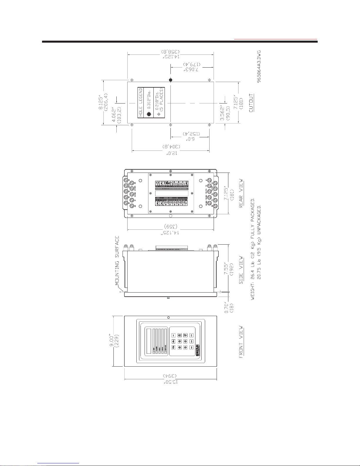
2.1 Physical Dimensions
The 169 relay is contained in a compact plastic and metal housing with the keypad, display, and all indicators located
on the front panel. The physical dimensions of the 169 unit are given in Figure 2-1.
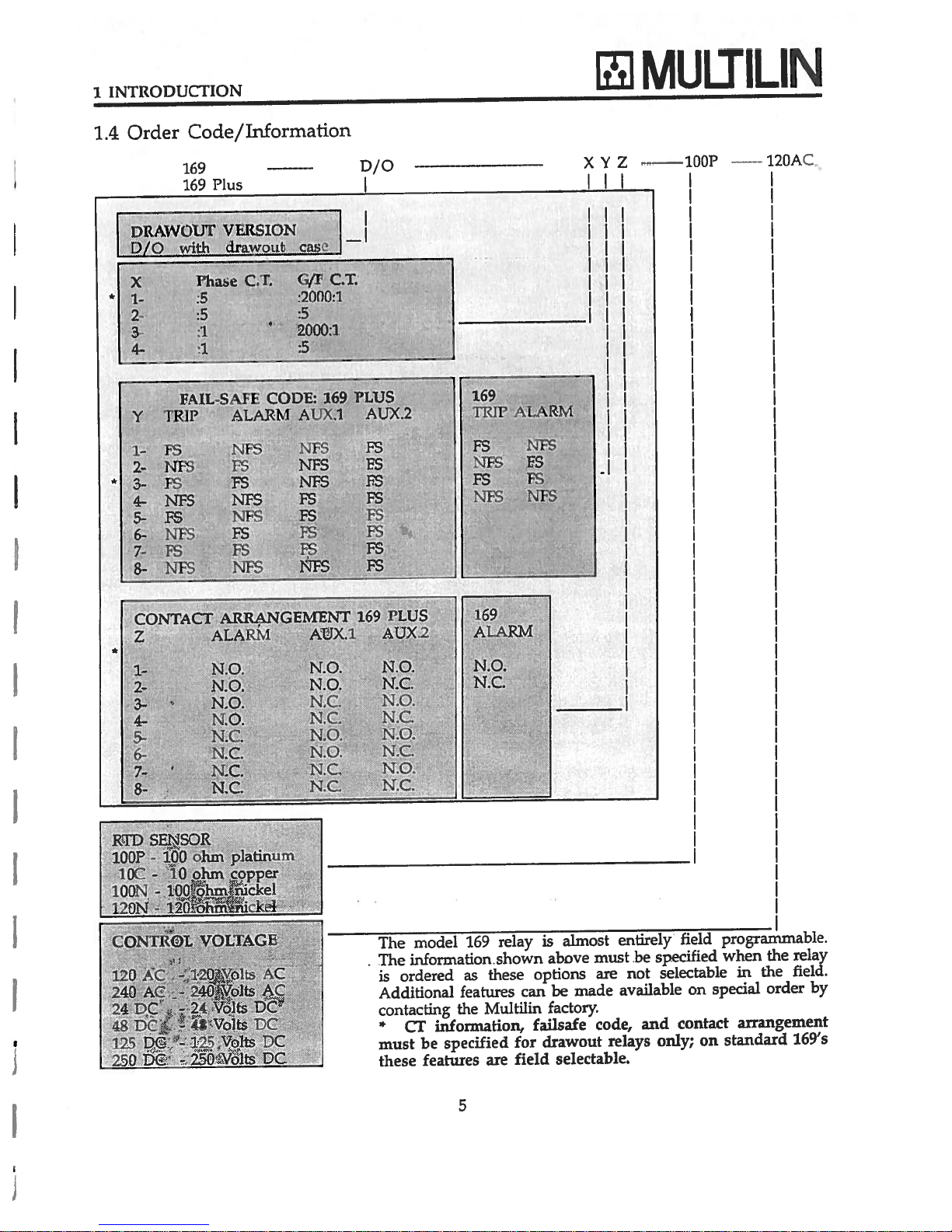
Multilin also provides phase and ground fault CTs if required. Dimensions for these are shown in Figure 2-2. Note:
Dimensions of Figure 2-2 are for 100:5 to 1000:5 phase CT's, for the dimensions of 50:5 and 75:5 CT's, consult
factory.
Figure 2-1 Physical Dimensions
7
Page 14
2 INSTALLATION
g
GE Power Management
Figure 2-2 CT Dimensions
8
Page 15
2 INSTALLATION
g
GE Power Management
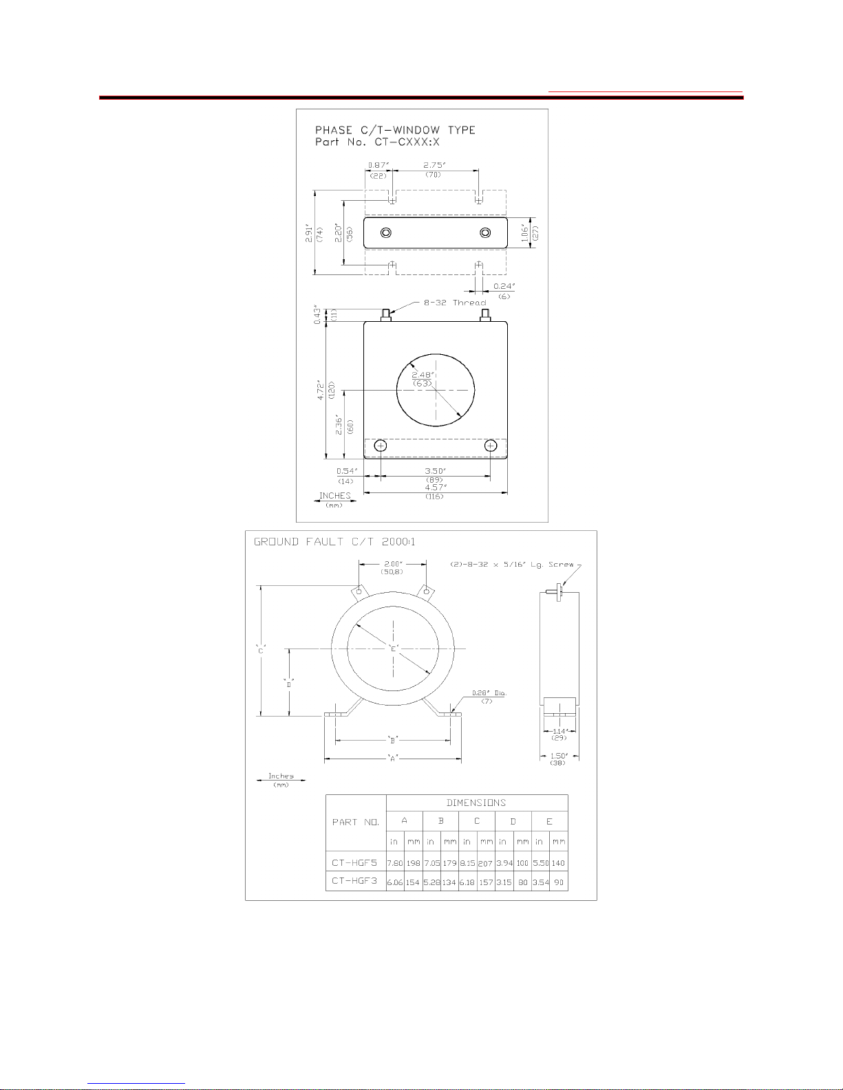
2.2 Mounting
The 169 should be positioned so that the display is visible and the front panel keypad is accessible. A cut-out is
made in the mounting panel and the unit is mounted as shown in Figure 2-3. Four washers and 10-32 X 3/8"
mounting screws are provided.
Although the 169 circuitry is internally shielded, to minimize noise pickup and interference the relay should be placed
away from high current conductors or sources of strong magnetic fields.
Connections to the relay are made through terminal blocks and CTs located on the rear of the unit.
Figure 2-3 Relay Mounting
9
Page 16

2 INSTALLATION
g
GE Power Management
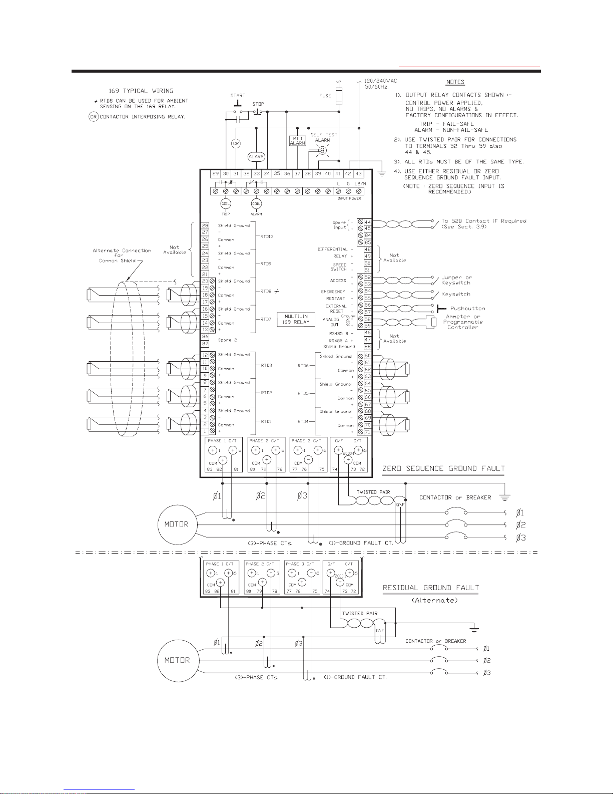
2.3 External Connections
The connections made to the 169 relay will vary depending on the programming of the unit. It is not necessary to
use all of the connections provided; a minimal configuration would include supply power, three phase current CT
inputs and the Trip relay contacts wired in series with the contactor control relay or circuit breaker shunt trip coil.
Connections to these and the other terminals outlined below will be explained in the following sections. Figures 2-4,
2-6, 2-7 show typical connections to the 169 relay.
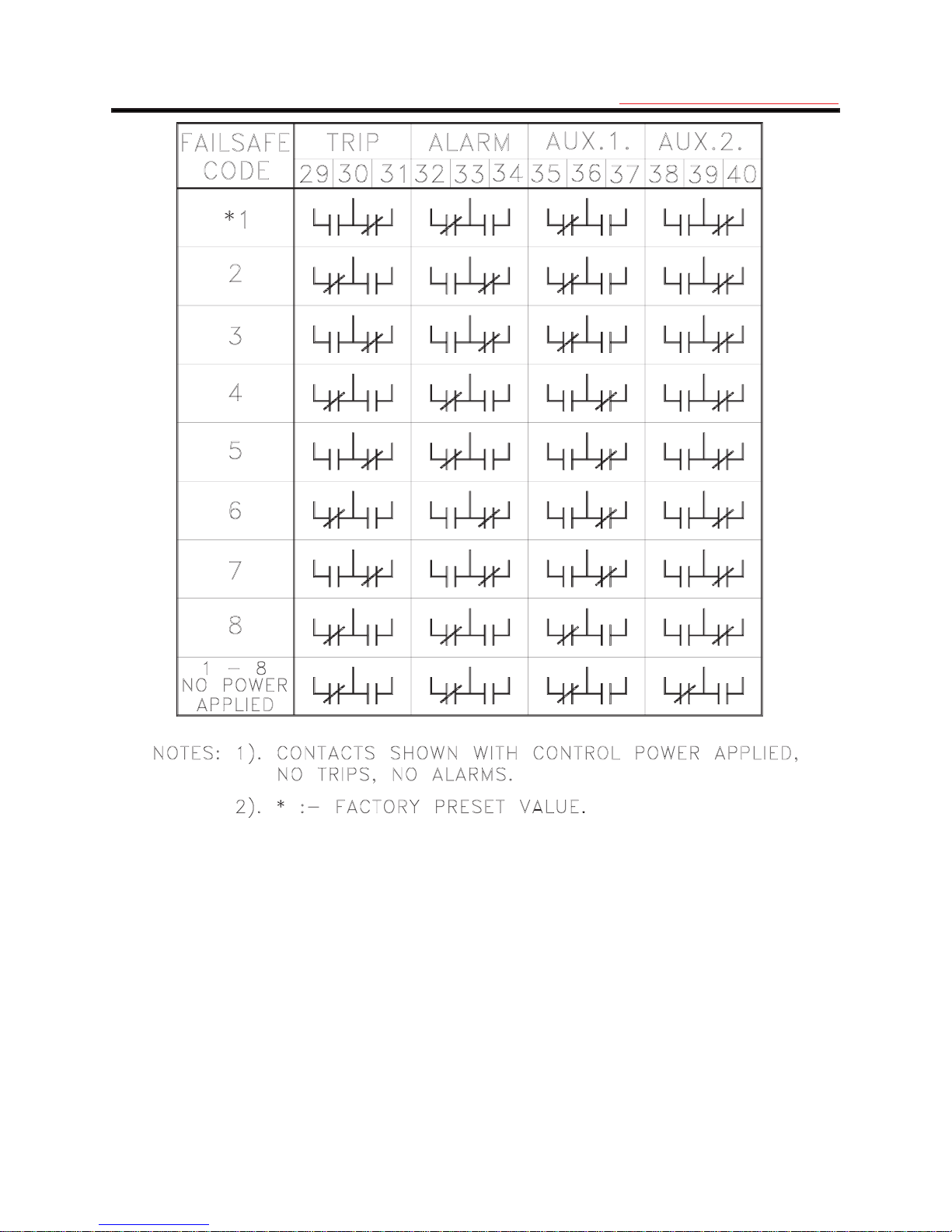
NOTE: The rear of the 169 relay shows output relay contacts in their power down state. Figures 2-4, 2-6, 2-7 show
output relay contacts with power applied, no trips or alarms, Factory Configurations, i.e. TRIP - fail-safe, ALARM non-fail-safe, AUX.1 - non-fail-safe, AUX.2 - fail-safe). See Figure 2-5 for a complete list of all possible output relay
contact states. See page 62 for a description of the RELAY FAILSAFE CODE.
Table 2-1 169 External Connections
Inputs
Supply Power L, G, N
•
Phase CTs
•
Ground Fault CTs
•
6 Stator RTDs
•
2 additional RTDs on the 169, 4 on the 169 Plus
•
Emergency Restart keyswitch
•
External Reset pushbutton
•
Programming Access jumper or keyswitch
•
Speed Switch input on the 169 Plus
•
Differential Relay input on the 169 Plus
•
Spare Input on the 169 Plus
•
Outputs
2 Sets of Relay Contacts (NO/NC) on the 169, 4 on the 169 Plus
•
Programmable Analog Current Output Terminals
•
RS 422 Serial Communication Port on the 169 Plus
•
10
Page 17
2 INSTALLATION
g
GE Power Management
Figure 2-4 Relay Wiring Diagram (AC control power)
11
Page 18
2 INSTALLATION
g
GE Power Management
WARNING: In locations where system voltage disturbances cause voltage levels to dip below the range
specified in specifications (1.5), any relay contact programmed failsafe may change state. To avoid tripping
the motor in this case, trip relay contacts should be programmed non-failsafe.
Figure 2-5 Output Relay Contact States
12
Page 19
2 INSTALLATION
g
GE Power Management
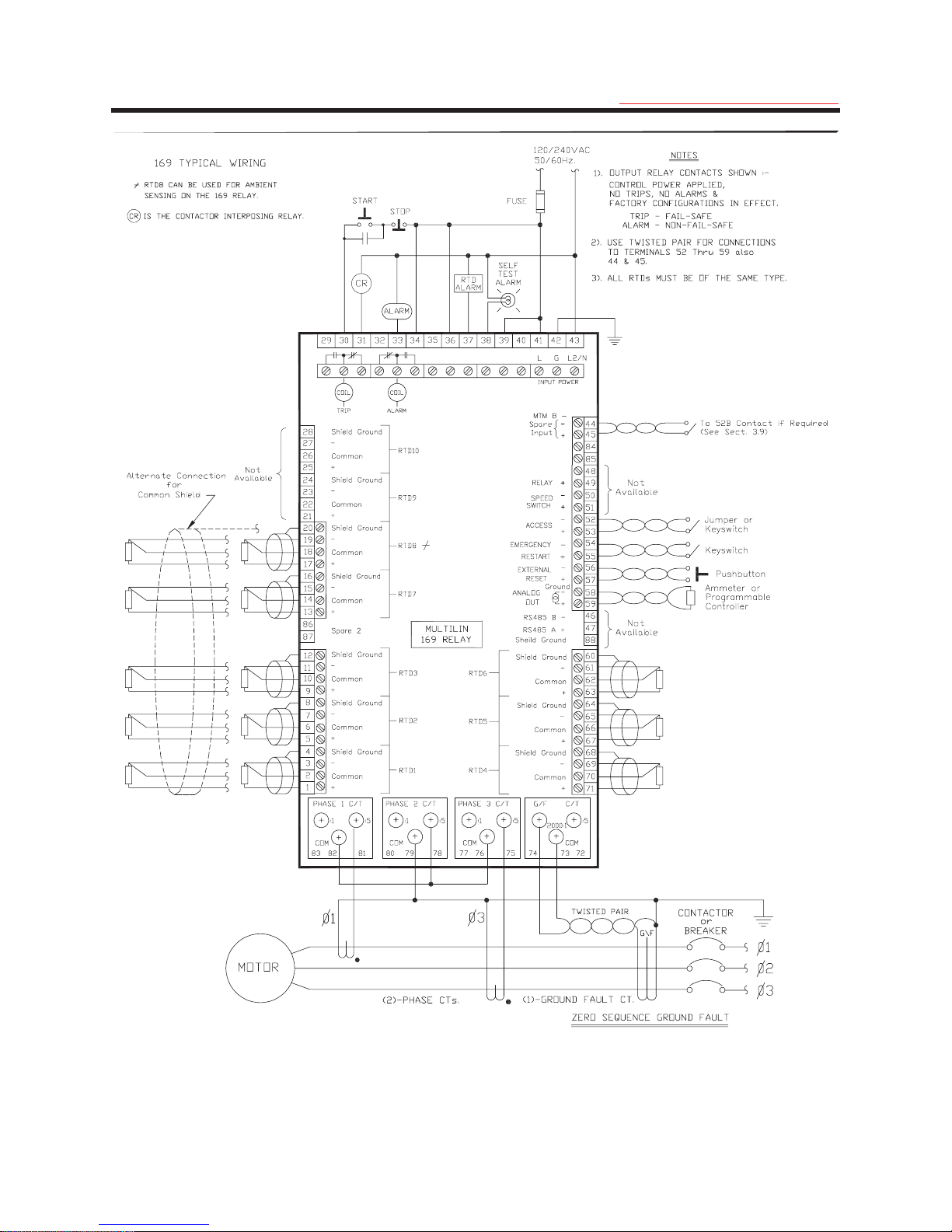
Figure 2-6 Relay Wiring Diagram (Two Phase CTs)
13
Page 20
2 INSTALLATION
g
GE Power Management
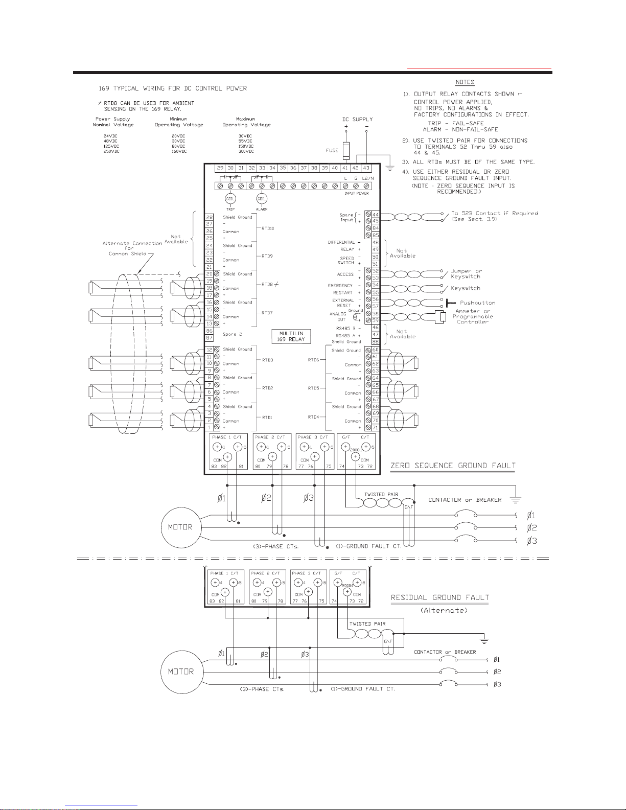
Figure 2-7 Relay Wiring Diagram (DC Control Power)
14
Page 21

2 INSTALLATION
g
GE Power Management
2.4 Control Power
Control power for the relay is nominally either 120/240 VAC at 50 Hz/60 Hz or either 24, 48, 125, or 250 VDC. The
AC voltage is selected by means of a slide switch on the power supply circuit board as shown in Figure 2-8. If an
alternative voltage is selected, ensure that the control power label on the back of the 169 Relay reflects the change.
This board is accessed by removing the perforated cover on the rear of the unit. The switch must be correctly set
before control power is applied to the 169. Maximum power consumption for the unit is 40 VA (AC version) or 30 W
(DC version).
The 169 will operate properly over a wide range of supply voltages typically found in industrial environments (see
control power specifications in section 1.5). When the supply voltage drops below the minimum, the output relays
will return to their power down states but all setpoints and statistical data will remain stored in the relay memory.
Motor lock-out time will be adhered to with or without control power applied.
Control power must be applied to the 169 relay, and the relay programmed, before the motor is energized. Power is
applied at terminals 41, 42, and 43 which is a terminal block having #6 screws.
NOTE: Chassis ground terminal 42 must be connected directly to the dedicated cubicle ground conductor to
prevent transients from damaging the 169/169 Plus resulting from changes in ground potential within the
cubicle.
Figure 2-8 AC Voltage Selection (120/240 VAC models only)
2.5 Phase CTs
One CT for each of the three motor phases is required to input a current into the relay proportional to the motor
phase current. The phase sequence must be as shown in Figures 2-4 and 2-7 in order for the phase reversal
function to operate properly. If two phase CTs are used as shown in Figure 2-6 the phase reversal function cannot
be used (see section 3.19). The CTs used can have either a 1 amp or 5 amp secondary and should be chosen so
that the motor full load current is between 50 and 95 percent of the rated CT primary amps. The CT ratio should
thus be of the form n:1 or n:5 where n is between 20 and 1500. The ratio of the CT used must be programmed into
the 169 (see section 3.7).
The CT connections to the relay are made between the ":1" and "COM" terminals for 1 amp CTs or between the ":5"
and "COM" terminals for CTs with a 5 amp secondary. The connections to the 169 internal phase CTs are made
directly via #10 screws.
AC VOLTAGE SELECTION SWITCH
A100 PC BOARD
15
Page 22

2 INSTALLATION
g
GE Power Management
2.6 Ground Fault CT
All current carrying conductors must pass through a separate ground fault CT in order for the ground fault function to
operate correctly. If a safety ground is used it should pass outside the CT window.
The ground fault CT is connected to terminals 73 and 72 for 5 amp secondary CTs or to terminals 73 and 74 for
Multilin 2000:1 CTs. as shown in Figures 2-4, 2-6, 2-7. The polarity of the ground fault CT connection is not
important. It is recommended that the two CT leads be twisted together to minimize noise pickup. If a 2000:1 ground
fault CT is used, the secondary output will be a low level signal which allows for sensitive ground fault detection.
The zero sequence ground fault connection is recommended. If the residual ground fault method is used the 169
relay will not display ground fault current in direct primary amps.
The connections to the 169 internal ground fault CT are made directly via #10 screws.
2.7 Trip Relay Contacts
The main control relay or shunt trip coil of the motor starter or circuit breaker should be connected to the Trip relay
contacts of the 169. These contacts are available as normally open (NO), normally closed (NC), and can switch up
to 10 amps at either 250 VAC or 30 VDC with a resistive load. Silver cadmium oxide contacts are used because of
their ability to handle high inrush currents on inductive loads. Contact Multilin if these contacts are to be used for
carrying low currents since they are not recommended for use below 0.1 amps. Connection to the motor contactor
or breaker is shown in Figures 2-4, 2-6, 2-7.
The Trip output relay will remain latched after a trip. This means that once this relay has been activated it will remain
in the active state until the 169 is manually reset. The Trip relay contacts may be reset by pressing the RESET key
(see section 3.1) if motor conditions allow, or by using the Emergency Restart feature (see section 2.12). An
optional single shot restart can be selected on the 169 Plus to automatically reset the relay after a running
OVERLOAD TRIP. This feature is selected or defeated in page 5 of SETPOINTS mode.
The Trip relay may be programmed to be fail-safe or non-fail-safe. W hen in the fail-safe mode, relay activation or a
loss of power condition will cause the relay contacts to go to their power down state. Thus, in order to cause a trip
on loss of power to the 169, output relays should be programmed as fail-safe.
The Trip relay cannot be reset if a lock-out is in effect. Lock-out time will be adhered to regardless of whether control
power is present or not.
The Trip relay can be programmed to activate on any combination of the following trip conditions: overload, stator
RTD overtemperature, rapid trip, unbalance, ground fault, short circuit, RTD overtemperature, phase reversal,
acceleration time, number of starts per hour, single phase, speed switch closure on start, differential relay closure,
spare input closure, and start inhibit (see section 3.4 for factory preset configurations). Connections to the Trip relay
contacts are made via a terminal block which uses #6 screws.
NOTE: The rear of the 169 relay shows output relay contacts in their power down state. Figures 2-4, 2-6, 2-7
show output relay contacts with power applied, no trips or alarms, and Factory Configurations in effect (i.e.
TRIP - fail-safe, ALARM - non-fail-safe, AUX.1 - non-fail-safe, AUX.2 - fail-safe). See Figure 2-5 for a list of all
possible contact states.
2.8 Alarm Relay Contacts
These contacts are available as normally open (NO), normally closed (NC), with the same ratings as the Trip relay
but can only be programmed to activate when alarm setpoint levels are reached. (On a Draw-out version of 169,
only one set of alarm contacts is available and the user must specify normally open or normally closed when
ordering). Thus these contacts may be used to signal a low level fault condition prior to motor shut-down.
Conditions which can be programmed to activate the relay are alarm levels for the following functions: immediate
overload, unbalance, undercurrent, ground fault, stator RTD overtemperature, RTD overtemperature, broken RTD
sensor, spare input alarm, self-test alarm, and start inhibit (see section 3.4 for factory preset configurations). The
relay can be configured as latched or unlatched and fail-safe or non-fail-safe. Connections to the Alarm relay
contacts are made via a terminal block which uses #6 screws.
NOTE: The rear of the 169 relay shows output relay contacts in their power down state. Figures 2-4, 2-6, 2-7 show
output relay contacts with power applied, no trips or alarms, and Factory Configurations in effect (i.e. TRIP - fail-safe,
ALARM - non-fail-safe, AUX.1 - non-fail-safe, AUX.2 - fail-safe). See Figure 2-5 for a list of all possible contact
states.
16
Page 23

2 INSTALLATION
g
GE Power Management
2.9 Auxiliary Relay #1 Contacts (169 Plus)
Auxiliary relay #1 is provided to give an extra set of NO/NC contacts which operate independently of the other relay
contacts. (On a Draw-out version of 169, only one set of Aux.1 contacts is available and the user must specify
normally open or normally closed when ordering). This auxiliary relay has the same ratings as the Trip relay.
Auxiliary relay #1 can be configured as latched or unlatched and fail-safe or non-fail-safe. The conditions that will
activate this relay can be any trip or alarm indications (see section 3.4 for factory preset configurations).
These contacts may be used for alarm purposes or to trip devices other than the motor contactor. For example, the
ground fault and short circuit functions may be directed to Auxiliary relay #1 to trip the main circuit breaker rather
than the motor starter.
Connections to the relay contacts are made via a terminal block which uses #6 screws.
NOTE: The rear of the 169 relay shows output relay contacts in their power down state. Figures 2-4, 2-6, 2-7
show output relay contacts with power applied, no trips or alarms, and Factory Configurations in effect (i.e.
TRIP - fail-safe, ALARM - non-fail-safe, AUX.1 - non-fail-safe, AUX.2 - fail-safe). See Figure 2-5 for a list of all
possible contact states.
2.10 Auxiliary Relay #2 Contacts (169 Plus)
This relay provides another set of NO/NC contacts with the same ratings as the other relays. (On a Draw-out version
of 169, only one set of Aux.2 contacts is available and the user must specify normally open or normally closed when
ordering). This relay is different from the others in the fact that it is permanently programmed as latched and failsafe.
This relay may be programmed to activate on any combination of alarm conditions (see section 3.4 for factory preset
configurations). The feature assignment programming is thus the same as for the Alarm relay.
Connections to the relay contacts are made via a terminal block which uses #6 screws.
NOTE: The rear of the 169 relay shows output relay contacts in their power down state. Figures 2-4, 2-6, 2-7
show output relay contacts with power applied, no trips or alarms, and Factory Configurations in effect (i.e.
TRIP - fail-safe, ALARM - non-fail-safe, AUX.1 - non-fail-safe, AUX.2 - fail-safe). See Figure 2-5 for a list of all
possible contact states.
2.11 RTD Sensor Connections
Up to six resistance temperature detectors (RTDs) may be used for motor stator temperature monitoring. The
remaining RTD inputs may be used for motor and load bearing, or other temperature monitoring functions. All RTDs
must be of the same type. RTD #8 (RTD #10 on the 169 Plus) may be used to monitor ambient air temperature.
This is done to enhance protection in environments where the ambient temperature varies considerably. Use of
stator RTDs will allow the 169 to "learn" the actual cooling times of the motor. W hen no stator RTDs are used the
169 will not learn the actual motor cooling times, but will rely on the user defined preset values. The number of
stator RTDs used together with RTD trip and alarm temperatures must be programmed into the 169 (see sections
3.16, 3.17). The RTD type to be used must be specified when ordering the 169 relay. If the type of RTD in use is to
be changed, the 169 must be returned to the factory.
Each RTD has four connections to the 169 relay as shown in Figures 2-4, 2-6, 2-7. Since the RTD indicates
temperature by the value of its resistance, it is necessary to compensate for the resistance of the connecting wires,
which is dependent on lead length and ambient temperature. The 169 uses a circuit to cancel this resistance and
read only the actual RTD resistance. Correct operation will occur providing all three wires are of the same length and
the lead resistance is not greater than 25% of the RTD 0 C resistance. This can be accomplished by using identical
lengths of the same type of wire. If 10 copper RTDs are to be used special care should be taken to keep the lead
resistance as low as possible.
If RTD #8 (RTD #10 on the 169 Plus) is to be used for ambient air temperature measurement the RTD should be
placed and mounted somewhere in the motor cooling air intake flow. The sensor should be in direct contact with the
cooling air but not with any surface that is at a temperature other than the cooling air. This RTD is selected for
ambient temperature use in page 5 of SETPOINTS mode.
If no RTD sensor is to be connected to any of the RTD terminals on the 169, the terminals may be left open.
If fewer than 6 stator RTDs are to be employed, they should be connected to the lowest numbered relay RTD
connections. For example, if 3 stator RTDs are to be used they should be connected to the terminals for RTD1,
17
Page 24

2 INSTALLATION
RTD2, and RTD3 (terminals #1-12). Other RTDs should be connected to the terminals for RTD7-RTD10 (terminals
#13-28) as shown in Figure 2-4.
The connections are made via terminal blocks which can accommodate up to #12 AWG multi-strand wire.
Note: Shielded, three wire cable must be used in industrial environments to prevent noise pickup. Wherever
possible, the RTD leads should be kept close to grounded metal casings and avoid areas of high
electromagnetic or radio frequency fields. RTD leads should not run adjacent to, or in the same conduit as
high current carrying wires. It is recommended to use a three wire shielded cable of #18 AWG copper
conductors. The shield connection of the RTD should not be grounded at the sensor end as there is an
internal ground on the 169. This arrangement prevents noise pickup that would otherwise occur from
circulating currents due to differences in ground potentials on a doubly grounded shield.
g
GE Power Management
2.12 Emergency Restart Terminals
If it is desired to occasionally override relay trips or lock-outs and restart the motor, a normally open keyswitch
should be installed between terminals 54 and 55. Momentarily shorting these terminals together will cause the
thermal memory of the 169 to discharge to 0% (if RTD input to thermal memory is enabled, thermal memory can be
reduced to 0% by keeping terminals 54 and 55 shorted together for more than 11 seconds; see section 3.20). The
Emergency Restart terminals can thus be used to override an OVERLOAD TRIP. Shorting the Emergency Restart
terminals together will also decrement the relay's internal starts/hour counter by 1 and therefore allow the operator to
override a STARTS/HOUR TRIP.
Note: This option should be used only when an immediate restart after a lock-out trip is required for process
integrity or personnel safety. Discharging the thermal memory of the 169 gives the relay an unrealistic value
for the thermal capacity remaining in the motor and it is possible to thermally damage the motor by
restarting it. Thus, complete protection may be compromised in order to restart the motor using this feature.
A twisted pair of wires should be used. Connection to the 169 is made via a terminal block which can accommodate
up to #12 AWG multi-strand wire.
2.13 External Reset Terminals
An external reset switch, which operates similarly to the keypad RESET key (see section 3.1), can be connected to
terminals 56 and 57 for remote reset operation. The switch should have normally open contacts. Upon closure of
these contacts the relay will be reset. This external reset is normally equivalent to pressing the keypad RESET key
but a special reset feature can be selected on page 5 of setpoints mode, so that the keypad RESET key will not
cause Auxiliary relay #1 to be reset (see section 3.22). Keeping the External Reset terminals shorted together will
cause the 169 to be reset whenever motor conditions allow.
A twisted pair of wires should be used. Connection to the 169 is made via a terminal block which can accommodate
up to #12 AWG multi-strand wire.
2.14 Analog Output Terminals (Non-Isolated)
Terminals 58 and 59 of the 169 are available for an analog current output representing one of percentage of motor
thermal capacity used, motor current as a percentage of full load (i.e. 0-1 XFLC), hottest stator RTD temperature as
a percentage of 200 C or CT secondary current as a percentage of CT secondary amps rating. The choice of output
is selected in page 5 of SETPOINTS mode. This selection can be made or changed at any time without affecting the
protective features of the relay.
The output current range is standard at 4-20 mA. Contact Multilin if a different current range is required. 4 mA
output corresponds to a low scale reading (i.e. 0% thermal capacity used, 0 XFLC phase current, 0 C hottest stator
RTD temperature, or 0 A phase CT secondary current). 20 mA output current corresponds to a high scale reading
(i.e. 100% thermal capacity used, 1 XFLC or greater phase current, 200 C or greater hottest stator RTD temperature,
or either 1 A (or greater) or 5 A (or greater) phase CT secondary depending on the CT used).
This output is a current source suitable for connection to a remote meter, chart recorder, programmable controller, or
computer load. Current levels are not affected by the total lead and load resistance as long as it does not exceed
300 for the 4-20 mA range. For readings greater than 100% of full scale the output will saturate at 20.2 mA.
This analog output is not isolated. Terminal 58 is internally connected to system ground. Consequently the negative
terminal of the connected load device must be at ground potential.
18
Page 25

2 INSTALLATION
A twisted pair of wires should be used. Connection to the 169 is made via a terminal block which can accommodate
up to #12 AWG multi-strand wire.
g
GE Power Management
2.15 Differential Relay Terminals (169 Plus)
Terminals 48 and 49 are provided for connection to a differential relay. This allows an external differential relay to be
connected to a 169 Plus relay. A contact closure between these terminals will cause an immediate activation of the
output relay assigned to the differential relay input function. After a DIFFERENTIAL INPUT TRIP terminals 48 and
49 must be open circuited in order to reset the relay.
If no differential relay is to be used terminals 48 and 49 should be left open.
A twisted pair of wires should be used. Connection to the 169 is made via a terminal block which can accommodate
up to #12 AWG multi-strand wire.
2.16 Speed Switch Terminals (169 Plus)
Terminals 50 and 51 are provided for connection to an external speed switch. This allows the 169 Plus relay to
utilize a speed device for locked rotor protection.
terminals 50 and 51 occurs within the "SPEED SWITCH TIME DELAY" (SETPOINTS, page 5) the output relay
assigned to the speed switch function will activate. This function must be enabled in order for operation to occur
(SETPOINTS, page 5). After a SPEED SWITCH TRIP terminals 50 and 51 must be open circuited in order to reset
the relay.
If no speed switch is to be used terminals 50 and 51 should be left open.
A twisted pair of wires should be used. Connection to the 169 is made via a terminal block which can accommodate
up to #12 AWG multi-strand wire.
During a motor start attempt
if no contact closure between
2.17 Programming Access Terminals
When a jumper wire is connected between ACCESS terminals 52 and 53 all setpoints and configurations can be
programmed using the keypad. Once programming is complete the jumper will normally be removed from these
terminals. When this is done all actual and setpoint values can still be accessed for viewing; however, if an attempt
is made to store a new setpoint value the message "ILLEGAL ACCESS" will appear on the display and the previous
setpoint will remain intact. In this way all of the programmed setpoints will remain secure and tamperproof.
Alternatively, these terminals can be wired to an external keyswitch to permit setpoint programming upon closure of
the switch.
A twisted pair of wires should be used for connection to an external switch. Connection to the 169 is made via a
terminal block which can accommodate up to #12 AWG multi-strand wire.
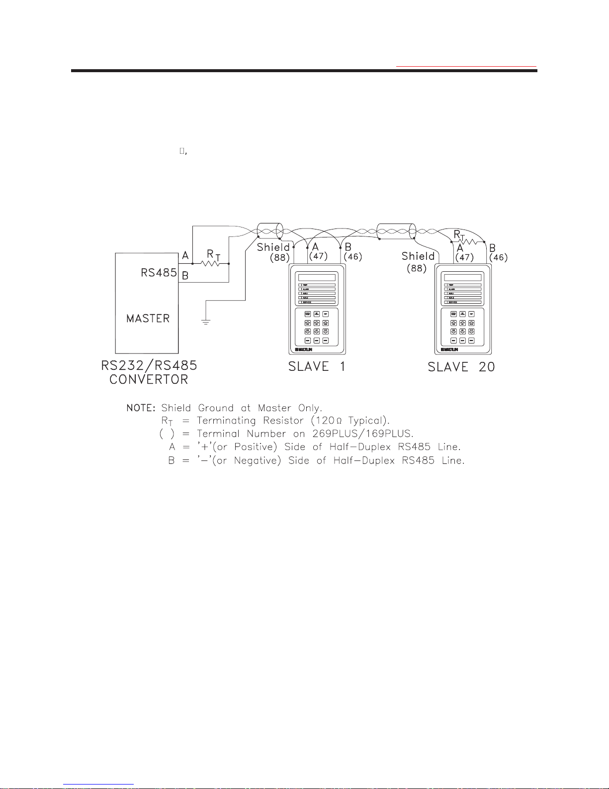
2.18 RS-422 Serial Communications Terminals (169 Plus)
Terminals 46 and 47 are provided for a digital serial communication link with other 169 Plus relays, computers, or
programmable controllers. Up to 20 169 Plus "SLAVES" can be connected to one "MASTER" (169 Plus or other
device) as shown in Figure 2-9. If devices other than 169 Plus relays are to be connected in the serial link a copy of
the "Multilin 169 Plus Relay Communication Protocol" will be required. This can be obtained by contacting Multilin.
Note that when using a device other than a 169 Plus to program a 169 Plus SLAVE, setpoints sent to the SLAVE
must be within the ranges listed in Table 3-3.
Each communication link must have only one MASTER. If the MASTER is a 169 Plus this relay cannot be used for
motor protection. Only relays programmed as SLAVEs can be used for motor protection. The MASTER should be
centrally located and can be used to view ACTUAL VALUES and SETPOINTS from each relay SLAVE. SETPOINTS
in each SLAVE can also be changed from the MASTER. In order to do this the MASTER relay must have its Access
terminals (52,53) shorted together.
Relays are programmed as MASTER or SLAVE using the last 2 setpoints of page 5 of SETPOINTS mode (see
section 3.4). Each SLAVE in the communication link must be programmed with a different SLAVE ADDRESS.
When a relay is programmed as a MASTER it will display all of the ACTUAL VALUES and SETPOINTS of the SLAVE
relay it is addressing. To view data from a different SLAVE the ADDRESSED SLAVE setpoint must be changed.
To avoid contention and improper reading of data ensure that the following conditions are met:
1. Each communication link has only one MASTER.
2. Each 169 Plus SLAVE in the link has a different SLAVE ADDRESS.
19
Page 26
2 INSTALLATION
The wires joining relays in the communication link should be a twisted pair. These wires should be routed away from
high power AC lines and other sources of electrical noise. The total length of the communications link should not
exceed 4000 feet. When connecting units in a communication link each 169 Plus relay must have terminal 47
connected to terminal 47 of the next unit in the link, and terminal 46 connected to terminal 46.
As shown in Figure 2-9 the first and last devices in the link should have a terminating resistor placed across
terminals 46 and 47. The value of these resistors should match the characteristic impedance of the line wire being
used. A typical value is 50 , 1/4 watt.
Connection to the 169 is made via a terminal block which can accommodate up to #12 AWG multi-strand wire.
Note: The difference in potentials between serial master ground and the 169 Plus slave (terminal 42) must
not exceed 10 volts. If a large difference in ground potentials does exist, communication on the serial
communication link will not be possible. In addition damage to the 169 Plus may result.
g
GE Power Management
Figure 2-9 Serial Communication Link Wiring
2.19 Display Adjustment
Once the 169 relay has been installed and input power applied, the contrast of the LCD display may have to be
adjusted. This adjustment has been made at the factory for average lighting conditions and a standard viewing
angle but can be changed to optimize the display readability in different environments. To alter the display contrast
the trimpot on the rear of the unit marked "CONTRAST" must be adjusted with a small slotted screwdriver.
2.20 Front Panel Faceplate
The front panel faceplate is composed of a polycarbonate material that can be cleaned with isopropyl or denatured
alcohol, freon, naphtha, or mild soap and water.
2.21 Spare Input Terminals (169 Plus)
Terminals 44 and 45 are provided for an additional relay contact input. A contact closure between these terminals
will cause a "SPARE INPUT TRIP" and/or a "SPARE INPUT ALARM" after the appropriate time delay (page 5 of
SETPOINTS). These terminals must be open circuited in order to reset the relay after a SPARE INPUT TRIP or
ALARM.
A twisted pair of wires should be used. Connection to the 169 is made via a terminal block which can accommodate
up to #12 AWG multi-strand wire.
20
Page 27

2 INSTALLATION
g
GE Power Management
2.22 169 Drawout Relay
The model 169 and 169 Plus relays are available in a drawout case option. The operation of the relay is the same
as described elsewhere in this manual except for the differences noted in this section. The physical dimensions of
the drawout relay are as shown in Figure 2-10. The relay should be mounted as shown in Figure 2-11.
The drawout 169 relay can be removed from service without causing motor shut-down. This can be useful for
replacing, calibrating, or testing units.
RELAY MOUNTING - Make cutout as shown and drill six 7/32" holes on mounting panel. Approximately 2-1/2"
should be clear at the top and bottom of the cutout in the panel for the hinged door. Ensure that the five #6-32 nuts
are removed from the threaded studs in the mounting flange and that the drawout chassis has been removed from
the drawout case. Install the case from the rear of the mounting panel by aligning the five #6-32 threaded case
studs to the previously drilled holes. With the studs protruding through the holes secure the case on the right hand
side with two #6-32 nuts provided. Install the hinged door on the front of the mounting panel using three #6-32 nuts
provided. There must be at least 1/2" clearance on the hinged side of the drawout relay to allow the door to open.
RELAY REMOVAL - Open the hinged door. Next remove the two ten finger connecting plugs making sure the top
one is removed first. Swivel the cradle-to-case hinged levers at each end of the 169 cradle assembly and slide the
assembly out of the case.
RELAY INSTALLATION - Slide the 169 cradle assembly completely into the case. Swivel the hinged levers in to lock
the 169 cradle assembly into the drawout case. Install the two ten finger connecting plugs making sure the bottom
plug is installed first. Close the hinged door and secure with the captive screw.
IMPORTANT NOTE:
withdrawn first. This isolates the 169 output relay contacts before power is removed from the relay. When installing
the drawout relay cradle assembly the bottom ten finger connecting plug must be installed first. This causes power
to be applied to the 169 relay before the output relay contacts are placed in the circuit.
After a 169 relay cradle assembly has been removed from the drawout case it is recommended that the hinged door
be closed in order to reduce the risk of electric shock.
Due to the hardware configuration of the drawout relay shorting bars, the RELAY FAILSAFE CODE (SETPOINTS,
page 5) should not be changed without consulting the factory. Wiring for the 169 Plus drawout is shown in Figure 2-
12. If it is required that any of the output relay configurations in Figure 2-12 be different than shown, this information
must be stated when the relay is ordered.
When removing the drawout relay cradle assembly the top ten finger connecting plug must be
21
Page 28
2 INSTALLATION
g
GE Power Management
Figure 2-10 169 Drawout Relay Physical Dimensions
22
Page 29

2 INSTALLATION
g
GE Power Management
Figure 2-11 169 Drawout Relay Mounting
23
Page 30

2 INSTALLATION
g
GE Power Management
Figure 2-12 169 Plus Drawout Relay Typical Wiring Diagram
24
Page 31

3 SETUP AND USE
g
GE Power Management
Figure 3-1 Front Panel Controls and Indicators
25
Page 32

3 SETUP AND USE
g
GE Power Management
3.1 Controls and Indicators
Once the 169 relay has been wired and control power applied, it is ready to be programmed for the given application.
Programming is accomplished using the 12 position keypad and 48 character alphanumeric display shown in Figure
3-1. The function of each key on the keypad and each of the indicators is briefly explained in Table 3-1.
Table 3-1 Controls and Indicators
No. Name Description
1 ACTUAL
VALUES
2 SET
POINTS
FUNCTION:
operating parameters. There are six pages of ACTUAL VALUES data:
page 1: Phase Current Data
•
page 2: RTD Temperature Data
•
page 3: Motor Capacity Data
•
page 4: Statistical Data
•
page 5: Pre-trip Data
•
page 6: Learned Parameters
•
EFFECT:
message
ACTUAL VALUES HAS SIX
PAGES OF DATA
will be displayed for 2 seconds. The beginning of page 1 of ACTUAL VALUES mode will
then be shown:
PAGE 1: ACTUAL VAL UES
PHASE CURRENT DATA
USE:
from page to page the PAGE UP and PAGE DOWN keys can be used. To go from line to
line within a page the LINE UP and LINE DOWN keys can be used.
FUNCTION:
other relay setpoints. There are six pages of setpoints data:
page 1: Motor Amps Setpoints
•
page 2: RTD Setpoints
•
page 3: O/L Curve Setpoints
•
page 4: Relay Configuration
•
page 5: System Configuration
•
page 6: Multilin Service Codes
•
The ACTUAL VALUES key allows the user to examine all of the actual motor
Pressing this key will put the relay into ACTUAL VALUES mode. The flash
This key can be pressed at any time, in any mode to view actual motor values. To go
The SET POINTS key allows the user to examine and alter all trip, alarm, and
26
Page 33

3 SETUP AND USE
No. Name Description
g
GE Power Management
EFFECT:
SETPOINTS HAS SIX
PAGES OF DATA
is displayed for 2 seconds. The beginning of page 1 of SETPOINTS mode is then shown:
PAGE 1: SETPOINT VALUES
MOTOR AMPS SETPOINTS
USE:
go from page to page the PAGE UP and PAGE DOWN keys can be used. To go from line to
line within a page the LINE UP and LINE DOWN keys can be used. To alter a setpoint, the
VALUE UP and VALUE DOWN keys can be used. All setpoints will increment and
decrement to pre-determined limits. When the desired value is reached, the STORE key
must be used to save the new setpoint. If an altered setpoint is not stored the previous
value will still be in effect. If the Access jumper is not installed a STORE will not be allowed
and the flash message "ILLEGAL ACCESS" will be displayed for 2 seconds.
3HELP
FUNCTION:
each of the other keys on the keypad and on each of the ACTUAL VALUES, SETPOINTS,
and TRIP/ALARM messages.
EFFECT:
the first line of a page (i.e. a page header) on the display the message,
Press KEY of interest or
HELP again for details
will be displayed. To obtain information on the function of a particular key, the key must be
pressed. To obtain information on the previously displayed ACTUAL VALUES,
SETPOINTS, or TRIP/ALARM message the HELP key should be pressed again. If this key
is pressed with any other message shown on the display, only information on the previous
line will be available.
Pressing this key will put the relay into SETPOINTS mode. The flash message,
This key can be pressed at any time, in any mode, to view or alter relay setpoints. To
The HELP key allows the user to obtain information on the function and use of
Pressing this key will put the relay into HELP mode. If this key is pressed with
4,5 PAGE
UP
PAGE
DOWN
6, 7 LINE UP
LINE DOWN
This key will have no effect when a flash message or HELP message is shown on
USE:
the display. Once HELP mode is entered the LINE UP and LINE DOWN keys can be used
to view the HELP message. The CLEAR key is used to exit from HELP mode and return to
the previous display mode. The ACTUAL VALUES and SET POINTS keys can also be
used to exit HELP mode.
FUNCTION:
previous pages of either ACTUAL VALUES or SETPOINTS modes. If either key is held for
more than 1/2 second the next or previous pages will be selected at a fast rate.
EFFECT:
next page of information. Pressing the PAGE UP key will cause the display to show the first
line of the previous page.
USE:
SETPOINTS modes.
FUNCTION:
previous lines of the currently selected page. If either key is held for more than 1/2 second
the next or previous lines will be selected at a fast rate.
The PAGE DOWN and PAGE UP keys allow the user to scan the next or
Pressing the PAGE DOWN key will cause the display to show the first line of the
These keys can be used any time the relay is in either the ACTUAL VALUES or
The LINE DOWN, and LINE UP keys allow the user to scan the next or
27
Page 34

3 SETUP AND USE
No. Name Description
g
GE Power Management
8,9 VALUE
UP
VALUE
DOWN
10 RESET
EFFECT:
currently selected page of information. Pressing the LINE UP key will cause the display to
show the line immediately in front of the currently displayed line.
USE:
shows the last line of a page the LINE DOWN key will have no effect. If the display shows
the first line of a page the LINE UP key will have no effect.
FUNCTION:
selected setpoint. If either key is held for more than 1/2 second the setpoint selected will
increment or decrement at a fast rate. If either key is held for more than 2 seconds the
setpoint selected will increment or decrement at a very fast rate.
EFFECT:
increment. Pressing the VALUE DOWN key will cause the currently displayed setpoint
value to decrement. For YES/NO questions, pressing either key will cause the answer to
change. Any changed setpoint will not be used internally until the STORE key is pressed.
USE:
when a YES/NO question is displayed in ACTUAL VALUES mode (see STORE key). When
the desired setpoint value is reached the STORE key is used to save it. If an altered
setpoint is not stored the previous value will still be in effect.
FUNCTION:
output relays have become active so that a motor start can be attempted.
EFFECT:
output relay contacts if motor conditions allow (see below). The message,
Pressing the LINE DOWN key will cause the display to show the next line of the
These keys can be used at any time in any relay mode of operation. If the display
The VALUE UP and VALUE DOWN keys allow the user to alter the currently
Pressing the VALUE UP key will cause the currently displayed setpoint value to
These keys can be pressed any time a setpoint is displayed in SETPOINTS mode or
The RESET key allows the user to reset the 169 after any of the latched
Pressing this key will reset (i.e. return to an inactive state) any of the active
11 CLEAR
RESET NOT POSSIBLE Condition still present
will be displayed if any active output relays cannot be reset
A latched relay cannot be reset if the trip/alarm condition persists (e.g. an
USE:
OVERLOAD TRIP lock-out or a high RTD temperature). Pre-trip motor values may be
viewed in ACTUAL VALUES mode page 5 (Pre-trip Data). If an immediate restart is
required after an OVERLOAD or STARTS/HOUR TRIP the Emergency Restart terminals
(see section 2.12) may be shorted together. This will reduce the lock-out time to 0 minutes.
FUNCTION:
non-stored setpoint to its original value. In HELP mode the CLEAR key allows the user to
return to the previous display mode.
EFFECT:
setpoint will be returned to its original value. When this key is pressed in HELP mode the
relay will return to the line and page of the mode active when the HELP key was pressed.
USE:
can only be used when a displayed setpoint has been changed with the VALUE UP/VALUE
DOWN keys but has not yet been stored. After a setpoint has been stored the CLEAR key
will have no effect. In HELP mode the CLEAR key can be used any time there is a HELP
message on the display.
In SETPOINTS mode the CLEAR key allows the user to return an altered,
When this key is pressed in SETPOINTS mode any altered, currently displayed
This key can be used in SETPOINTS or HELP modes only. In SETPOINTS mode it
28
Page 35

3 SETUP AND USE
No. Name Description
g
GE Power Management
12 STORE
FUNCTION:
internal memory.
EFFECT:
will be stored and will immediately come into effect. W hen a setpoint is stored the flash
message,
new setpoint stored
will appear on the display.
The STORE key can be pressed in ACTUAL VALUES mode to clear the maximum actual
temperature data. To do this the following message from page 2 of ACTUAL VALUES
mode must be displayed after the "NO" value is altered to say "YES" by pressing the
VALUE UP/VALUE DOWN key:
CLEAR LAST ACCESS DATA ?
YES
Then when the STORE key is pressed the following flash message will appear on the
display:
last access data cleared
The maximum actual temperature data (see section 3.24) will then be cleared. The STORE
key can be pressed in ACTUAL VALUES mode to start a new motor commissioning (i.e.
clear statistical data). To do this the following message from page 4 of ACTUAL VALUES
mode must be displayed after the "NO" value is altered to say "YES" by pressing the
VALUE UP/VALUE DOWN key:
The STORE key allows the user to store new setpoints into the 169 relay's
When this key is pressed in SETPOINTS mode the currently displayed setpoint
START COMMISSIONING?
YES
Then when the STORE key is pressed the following flash message will appear on the
display:
COMMISSIONI NG data
cleared
All statistical data (see section 3.24) will then be cleared.
The STORE key can be used only in SETPOINTS mode to store new setpoints, or in
USE:
ACTUAL VALUES mode to clear the maximum actual temperature data or start a new
commissioning (i.e. clear statistical data). This key will have no effect unless the Access
terminals are shorted together.
13 TRIP LED indicator used to show the state of the Trip output relay. W hen on, the trip relay is
active. When off, the Trip relay is inactive.
14 ALARM LED indicator used to show the state of the Alarm output relay. When on, the Alarm relay is
active. When off, the Alarm relay is inactive.
15 AUX. 1 LED indicator used to show the state of Auxiliary relay #1. When on, Aux. relay #1 is
active. When off, Aux. relay #1 is inactive.
16 AUX. 2 LED indicator used to show the state of Auxiliary relay #2. When on, Aux. relay #2 is
active. When off, Aux. relay #2 is inactive.
29
Page 36

3 SETUP AND USE
No. Name Description
17 SERVICE LED indicator used to show the result of the 169 self-test feature. When flashing, the relay
has failed the self-test and service is required. When on steady, the supply voltage may be
too low. This LED may be on momentarily during relay power up.
g
GE Power Management
3.2 169 Relay Display Modes
The 169 relay display is used for viewing actual motor values, setpoint values, HELP messages, and TRIP/ALARM
messages. This is accomplished by having the relay in one of four possible modes of operation:
1. ACTUAL VALUES mode
2. SETPOINTS mode
3. HELP mode
4. TRIP/ALARM mode
The relay will operate correctly, giving full motor protection, regardless of which display mode is currently in effect.
The different modes affect only the data that appears on the 169 relay's 48 character alphanumeric display.
TRIP/ALARM mode can only be entered by having one or more of the trip or alarm level setpoints exceeded. The
other display modes can be entered using the ACTUAL VALUES, SET POINTS, or HELP keys (see section 3.1).
The ACTUAL VALUES and SETPOINTS modes are based on a book-like system of "pages" and "lines". One line
from any page may be displayed at any given time. To "turn" a page, the PAGE UP and PAGE DOW N keys are
used. To scan the lines on a page the LINE UP and LINE DOWN keys are used. In the HELP and TRIP/ALARM
modes only the LINE UP and LINE DOWN keys are needed.
When control power is applied to the relay the following power up message will be displayed:
MULTILIN 169 RELAY
REVISION XXX XX/XX
or
MULTILIN 169 PLUS RELAY
REVISION XXX XX/XX
After this the display will show, (factory default settings)
I1= XXX I2= XXX
I3= XXX (AMPS) ---
which is in page 1 of ACTUAL VALUES mode.
A description of each display mode is given in the following sections.
3.3 ACTUAL VALUES Mode
In ACTUAL VALUES mode, any of the parameters monitored or calculated by the 169 relay may be viewed by the
user. This mode is divided into six separate pages of data each of which contains a different group of actual motor
values. The six pages and the lines in each page are as shown in Table 3-2.
30
Page 37

3 SETUP AND USE
Table 3-2 Actual Values
3$*( /,1( '(6&5,37,21
g
GE Power Management
11
12
13
14
15
16
PAGE 1: ACTUAL VALUES
PHASE CURRENT DATA
ACTUAL VALUES page 1 header.
MOTOR STARTING
###1###2###3###4###5###6
Motor starting current level (seen only during a motor start).
I1= XXXX I2= XXXX
I3= XXXX (AMPS) ---
Motor phase current data. ("---" becomes "RUN" when motor is running).
I(3 ph avg) = XXXX AMPS
Max Stator RTD = XXX C
Average of 3 phase currents. Maximum of 6 stator RTDs.
UNBALANCE RATIO (In/Ip)
U/B = XXX PERCENT
Ratio of negative to positive sequence currents.
GROUND FAULT CURRENT
G/F = XX.X AMPS
17
Actual ground fault current.
END OF PAGE ONE
ACTUAL VALUES
Last line of page 1.
31
Page 38

3 SETUP AND USE
3$*( /,1( '(6&5,37,21
g
GE Power Management
21
22
23
24
PAGE 2: ACTUAL VALUES
RTD TEMPERATURE DATA
ACTUAL VALUES page 2 header.
HOTTEST STATOR RTD
RTD # X = XXX C
Maximum stator RTD temperature.
STATOR TEMPERATURE
RTD #1= XXX DEGREES C
or
RTD TEMPERATURE
RTD #1= XXX DEGREES C
RTD #1 temperature.
STATOR TEMPERATURE
RTD #2= XXX DEGREES C
or
RTD TEMPERATURE
RTD #2= XXX DEGREES C
25
26
RTD #2 temperature.
STATOR TEMPERATURE
RTD #3= XXX DEGREES C
or
RTD TEMPERATURE
RTD #3= XXX DEGREES
RTD #3 temperature.
STATOR TEMPERATURE
RTD #4= XXX DEGREES C
or
RTD TEMPERATURE
RTD #4= XXX DEGREES C
RTD #4 temperature.
32
Page 39

3 SETUP AND USE
3$*( /,1( '(6&5,37,21
g
GE Power Management
27
28
29
210
STATOR TEMPERATURE
RTD #5= XXX DEGREES C
or
RTD TEMPERATURE
RTD #5= XXX DEGREES C
RTD #5 temperature.
STATOR TEMPERATURE
RTD #6= XXX DEGREES C
or
RTD TEMPERATURE
RTD #6= XXX DEGREES C
RTD #6 temperature.
RTD TEMPERATURE
RTD #7= XXX DEGREES C
RTD #7 temperature.
RTD TEMPERATURE
RTD #8= XXX DEGREES C
211
212
213
or
AMBIENT TEMPERATURE
RTD #8= XXX DEGREES C
RTD #8 temperature. Ambient seen when RTD #8 is used for ambient sensing on model 169.
RTD TEMPERATURE
RTD #9= XXX DEGREES C
RTD #9 temperature.
RTD TEMPERATURE
RTD #10= XXX DEGREES C
or
AMBIENT TEMPERATURE
RTD #10= XXX DEGREES C
RTD #10 temperature. Ambient seen when RTD #10 is used for ambient sensing on model 169.
MAX. STATOR SINCE LAST
ACCESS: RTD# X = XXX
Maximum stator RTD temperature since last access.
33
Page 40

3 SETUP AND USE
3$*( /,1( '(6&5,37,21
g
GE Power Management
214
215
216
217
218
219
MAXIMUM RTD#7 TEMP SINCE
LAST ACCESS: RTD# X = XXX
Maximum RTD #7 temperature since last access.
MAXIMUM RTD#8 TEMP SINCE
LAST ACCESS = XXX C
Maximum RTD #8 temperature since last access.
MAXIMUM RTD#9 TEMP SINCE
LAST ACCESS = XXX C
Maximum RTD #9 temperature since last access.
MAX. RTD# 10 TEMP SINCE
LAST ACCESS = XXX C
Maximum RTD #10 temperature since last access.
CLEAR LAST ACCESS DATA?
XXX
Used to clear the data in the last 5 lines (see section 3.1, STORE key).
END OF PAGE TWO
ACTUAL VALUES
Last line of page 2.
34
Page 41

3 SETUP AND USE
3$*( /,1( '(6&5,37,21
1
3
PAGE 3: ACTUAL VALUES
MOTOR CAPACITY DATA
ACTUAL VALUES page 3 header.
g
GE Power Management
32
33
34
35
ESTIMATED TIME TO
TRIP = XXX SECONDS
Estimated time to overload trip under present conditions (seen only during overloads).
MOTOR LOAD AS A PERCENT
FULL LOAD = XXX PERCENT
Actual motor current as a percentage of full load.
THERMAL CAPACITY
USED = XXX PERCENT
Percentage of motor thermal capacity used.
END OF PAGE THREE
ACTUAL VALUES
Last line of page 3.
35
Page 42

3 SETUP AND USE
3$*( /,1( '(6&5,37,21
g
GE Power Management
41
42
43
44
45
46
PAGE 4: ACTUAL VALUES
STATISTICAL DATA
ACTUAL VALUES page 4 header.
RUNNING HRS SINCE LAST
COMMISSIONING XXXXX HRS
Total motor running hours since last commissioning.
# OF STARTS SINCE LAST
COMMISSIONING XXX
Total number of motor starts since last commissioning.
# OF TRIPS SINCE LAST
COMMISSIONING XXX
Total number of relay trips since last commissioning.
# O/L TRIPS SINCE LAST
COMMISSIONING XXX
Total number of relay overload trips since last commissioning.
# RAPID TRIPS SINCE LAST
COMMISSIONING XXX
47
48
49
410
411
Total number of relay rapid trips since last commissioning.
# U/B TRIPS SINCE LAST
COMMISSIONING XXX
Total number of relay unbalance trips since last commissioning.
# G/F TRIPS SINCE LAST
COMMISSIONING XXX
Total number of relay ground fault and differential input trips since last commissioning.
# RTD TRIPS SINCE LAST
COMMISSIONING XXX
Total number of relay RTD trips since last commissioning.
# S/C TRIPS SINCE LAST
COMMISSIONING XXX
Total number of relay short circuit trips since last commissioning.
#START TRIPS SINCE LAST
COMMISSIONING XXX
Total number of acceleration time, phase reversal and speed switch trips since last commissioning.
36
Page 43

3 SETUP AND USE
3$*( /,1( '(6&5,37,21
g
GE Power Management
412
413
START NEW COMMISSIONING?
XXX
Used to clear the data in the last 10 lines (see section 3.1, STORE key).
END OF PAGE FOUR
ACTUAL VALUES
Last line of page 4.
37
Page 44

3 SETUP AND USE
3$*( /,1( '(6&5,37,21
g
GE Power Management
51
52
53
54
55
56
PAGE 5: ACTUAL VALUES
PRE-TRIP DATA
ACTUAL VALUES page 5 header.
PRE-TRIP AVERAGE MOTOR
CURRENT = XXXXX AMPS
Average motor phase current prior to last relay trip.
PRE-TRIP U/B RATIO
(In/Ip) XXX PERCENT
Ratio of negative to positive sequence currents prior to last relay trip.
PRE-TRIP G/F CURRENT
G/F = XXX AMPS
Ground fault current prior to last relay trip.
PRE-TRIP MAX STATOR RTD
RTD # X = XXX C
Maximum stator RTD temperature prior to last relay trip.
END OF PAGE FIVE
ACTUAL VALUES
Last line of page 5.
38
Page 45

3 SETUP AND USE
3$*( /,1( '(6&5,37,21
g
GE Power Management
61
62
63
64
65
66
PAGE 6: ACTUAL VALUES
LEARNED PARAMETERS
ACTUAL VALUES page 6 header.
LEARNED Istart (AVG.OF 4
STARTS) = XXX AMPS
Learned average motor starting current over past 4 starts.
LEARNED Istart (last one)
= XXX AMPS
Learned motor starting current from last start.
LEARNED K FACTOR
K = XX.X
Learned value of negative sequence K factor.
LEARNED RUNNING COOL
TIME= XXX MIN.
Learned motor cooling time with motor running (see section 3.20).
LEARNED STOPPED COOL
TIME= XXX MIN.
67
68
69
* 169 Plus only
Learned motor cooling time with motor stopped (see section 3.20).
LEARNED ACCEL. TIME
ACCEL. TIME = XX.X SEC.
Learned motor acceleration time.
LEARNED Start Capacity
required = XX PERCENT
Learned motor thermal capacity used during a start.
END OF PAGE SIX
ACTUAL VALUES
Last line of page 6.
39
Page 46

3 SETUP AND USE
To place the relay in ACTUAL VALUES mode, the ACTUAL VALUES key must be pressed. When this is done the
following flash message will appear for 2 seconds,
ACTUAL VALUES HAS SIX
PAGES OF DATA
The display will then show,
PAGE 1: ACTUAL VAL UES
PHASE CURRENT DATA
which is the beginning of page 1.
If the relay is in SETPOINTS mode or ACTUAL VALUES mode and no key is pressed for more than four minutes the
display will change to, (factory default settings)
I1= XXX I2= XXX
I3= XXX (AMPS) ---
which is the third line in page 1 of ACTUAL VALUES mode. This default display line can be changed in page 5 of
SETPOINTS mode.
When in this mode the PAGE UP, PAGE DOW N, LINE UP, and LINE DOWN keys (see section 3.1) can be used to
examine all of the actual motor data outlined above.
g
GE Power Management
40
Page 47

3 SETUP AND USE
g
GE Power Management
3.4 SETPOINTS Mode
In SETPOINTS mode any or all of the motor trip/alarm setpoints may be either viewed or altered. This mode is
divided into six separate pages of data each of which contains a different group of relay setpoints.
To enter SETPOINTS mode the SET POINTS key must be pressed. When in this mode, if no key is pressed for
more than four minutes, the display will automatically go into ACTUAL VALUES mode as explained in section 3.3.
To return to SETPOINTS mode the SET POINTS key must be pressed. W hen this key is pressed the following flash
message will appear on the display,
SETPOINTS HAS SIX
PAGES OF DATA
Then the display will show,
PAGE 1: SETPOINT VALUES
MOTOR AMPS SETPOINTS
which is the first line of the first page of SETPOINTS mode. The PAGE UP, PAGE DOWN, LINE UP, and LINE
DOWN keys (see section 3.1) may then be used to view all of the SETPOINTS data.
When setpoints are to be changed, the VALUE UP, VALUE DOWN, STORE, and CLEAR keys (see section 3.1) are
used. The Access terminals must first be shorted together (see section 2.17). The PAGE UP, PAGE DOWN, LINE
UP, and LINE DOWN keys are used to display the setpoints that are to be changed. The setpoints themselves are
changed by pressing the VALUE UP or VALUE DOWN keys until the desired setpoint value is reached. To return the
setpoint to its original value the CLEAR key can be used. When the setpoint is adjusted to its proper value the
STORE key should be pressed in order to store the setpoint into the 169's internal memory. Once the STORE key is
pressed the flash message,
new setpoint stored
will appear on the display and the new setpoint value will be used by the 169 relay.
If an attempt is made to store a new setpoint value without the Access terminals shorted together the new value will
not be stored and the flash message,
ILLEGAL ACCESS
will appear on the display. To make the setpoints tamperproof the Access terminals should be shorted together only
when setpoints are to be changed.
Setpoints may be changed while the motor is running; however it is not recommended to change important
protection parameters without first stopping the motor.
Setpoints will remain stored indefinitely in the 169 relay's internal non-volatile memory even when control power to
the unit is removed.
All six pages of data and the lines in each page are as shown in Table 3-3. Also shown are the ranges and
increments for each setpoint. It should be noted that the 169 relay's motor protection parameters are based on the
data entered by the user. Thus this data must be complete and accurate for the given system.
41
Page 48

3 SETUP AND USE
Table 3-3 SETPOINTS
3$*( ,1)250$7,21 /,1( 5$1*( 0$18$/ 5()
1
PAGE 1: SETPOINTS VALUES
MOTOR AMPS SETPOINTS
g
GE Power Management
1
PHASE CT RATIO
SECONDARY = X AMP
1
PHASE CT RATIO
CT RATIO = XXXX:x
1
MOTOR FULL LOAD CURRENT
FLC= XXXX AMPS
1
ACCEL.TIME= XXX.X SECONDS
Consult motor data sheet
1
STARTS/HOUR= X
Consult motor data sheet
1
UNBALANCE ALARM LEVEL
U/B ALARM= XX PERCENT
1
U/B ALARM TIME DELAY
TIME DELAY = XXX SEC
1
UNBALANCE TRIP LEVEL
U/B TRIP= XX PERCENT
1
U/B TRIP TIME DELAY
U/B DELAY= XXX SECONDS
:1 or :5 3.7
20-1500 (increments of 1) 3.7
10-1500 amps (increments of 1) 3.7
0.5-125.0 or OFF (increments of 0.5) 3.8
1-5 starts or OFF (increments of 1) 3.9
4-30 % or OFF (increments of 1) 3.10
3-255 seconds (increments of 1) 3.10
4-30 % or OFF (increments of 1) 3.10
3-255 seconds (increments of 1) 3.10
1
G/F CT RATIO :5 ? XXX
(NO indicates 2000:1)
1
G/F CT RATIO
G/F CT = XXX:5
1
GROUND FAULT ALARM LEVEL
G/F ALARM= XXX AMPS
1
G/F ALARM TIME DELAY
TIME DELAY = XXX SEC
1
GROUND FAULT TRIP LEVEL
G/F TRIP = XXX AMPS
YES (5 amp secondary) or NO (2000:1) 3.11
50-250 (increments of 50)
(Not seen if ratio is 2000:1)
2000:1 CT: 1.0-10.0 amps or OFF (steps of 1.0)
5 A secondary CT: 10-100% of primary amps or
OFF (increments of 10%)
1-255 seconds (increments of 1) 3.11
2000:1 CT: 1.0-10.0 A or OFF (steps of 1.0)
5 A secondary CT: 10-100% of primary amps or
OFF (increments of 10% )
42
3.11
3.11
3.11
Page 49

3 SETUP AND USE
3$*( ,1)250$7,21 /,1( 5$1*( 0$18$/ 5()
g
GE Power Management
1
G/F TRIP TIME DELAY
G/F DELAY= XX.X SECONDS
1
UNDERCURRENT ALARM LEVEL
U/C ALARM= XXXX AMPS
1
UNDERCURRENT TIME DELAY
U/C DELAY= XXX SECONDS
1
RAPID TRIP / MECH. JAM
TRIP LEVEL= X.X X FLC
1
RAPID TRIP TIME DELAY
DELAY= XXX.X SECONDS
1
SHORT CIRCUIT TRIP LEVEL
S/C TRIP= XX X FLC
1
SHORT CIRCUIT TIME DELAY
S/C DELAY= XX.X SECONDS
1
IMMEDIATE OVERLOAD
LEVEL = X.XX X FLC
0.0 (Instantaneous) – 20.0 seconds (increments
of 0.5). Additional time delay of 0.25 seconds
following 20.0.
1-1000 amps or OFF (increments of 1) 3.12
1-255 seconds (increments of 1) 3.12
1.5xFLC-4.5xFLC or OFF (steps of 0.5xFLC) 3.13
0.5-125.0 seconds (increments of 0.5) 3.13
4xFLC-12xFLC or OFF (increments of 1xFLC) 3.14
Instantaneous or 0.5-20.5 sec. (steps of 0.5) 3.14
1.01xFLC-1.50xFLC or OFF (steps of 0.01xFLC) 3.15
3.11
1
END OF PAGE ONE
SETPOINT VALUES
43
Page 50

3 SETUP AND USE
3$*( ,1)250$7,21 /,1( 5$1*( 0$18$/ 5()
2
PAGE 2: SETPOINT VALUES
RTD SETPOINTS
g
GE Power Management
2
# OF STATOR RTDS USED
# OF RTDs = X
2
RTD #1 ALARM LEVEL
= XXX DEGREES C
or
STATOR #1 ALARM LEVEL
= XXX DEGREES C
2
RTD #1 TRIP LEVEL
= XXX DEGREES C
or
STATOR #1 TRIP LEVEL
= XXX DEGREES C
2
RTD #2 ALARM LEVEL
= XXX DEGREES C
or
STATOR #2 ALARM LEVEL
= XXX DEGREES C
0-6 (increments of 1) 3.16
0-200 degrees C or OFF (increments of 1) 3.16
0-200 degrees C or OFF (increments of 1) 3.16
0-200 degrees C or OFF (increments of 1) 3.16
2
RTD #2 TRIP LEVEL
= XXX DEGREES C
or
STATOR #2 TRIP LEVEL
= XXX DEGREES C
2
RTD #3 ALARM LEVEL
= XXX DEGREES C
or
STATOR #3 ALARM LEVEL
= XXX DEGREES C
2
RTD #3 TRIP LEVEL
= XXX DEGREES C
or
STATOR #3 TRIP LEVEL
= XXX DEGREES C
0-200 degrees C or OFF (increments of 1) 3.16
0-200 degrees C or OFF (increments of 1) 3.16
0-200 degrees C or OFF (increments of 1) 3.16
44
Page 51

3 SETUP AND USE
3$*( ,1)250$7,21 /,1( 5$1*( 0$18$/ 5()
g
GE Power Management
2
RTD #4 ALARM LEVEL
= XXX DEGREES C
or
STATOR #4 ALARM LEVEL
= XXX DEGREES C
2
RTD #4 TRIP LEVEL
= XXX DEGREES C
or
STATOR #4 TRIP LEVEL
= XXX DEGREES C
2
RTD #5 ALARM LEVEL
= XXX DEGREES C
or
STATOR #5 ALARM LEVEL
= XXX DEGREES C
2
RTD #5 TRIP LEVEL
= XXX DEGREES C
or
0-200 degrees C or OFF (increments of 1) 3.16
0-200 degrees C or OFF (increments of 1) 3.16
0-200 degrees C or OFF (increments of 1) 3.16
0-200 degrees C or OFF (increments of 1) 3.16
STATOR #5 TRIP LEVEL
= XXX DEGREES C
2
RTD #6 ALARM LEVEL
= XXX DEGREES C
or
STATOR #6 ALARM LEVEL
= XXX DEGREES C
2
RTD #6 TRIP LEVEL
= XXX DEGREES C
or
STATOR #6 TRIP LEVEL
= XXX DEGREES C
2
RTD #7 ALARM LEVEL
= XXX DEGREES C
2
RTD #7 TRIP LEVEL
= XXX DEGREES C
0-200 degrees C or OFF (increments of 1) 3.16
0-200 degrees C or OFF (increments of 1) 3.16
0-200 degrees C or OFF (increments of 1) 3.17
0-200 degrees C or OFF (increments of 1) 3.17
45
Page 52

3 SETUP AND USE
3$*( ,1)250$7,21 /,1( 5$1*( 0$18$/ 5()
g
GE Power Management
2
RTD #8 ALARM LEVEL
= XXX DEGREES C
2
RTD #8 TRIP LEVEL
= XXX DEGREES C
2
RTD #9 ALARM LEVEL
= XXX DEGREES C
2
RTD #9 TRIP LEVEL
= XXX DEGREES C
2
RTD #10 ALARM LEVEL
= XXX DEGREES C
*2
RTD #10 TRIP LEVEL
= XXX DEGREES C
2
END OF PAGE TWO
SETPOINT VALUES
0-200 degrees C or OFF (increments of 1) 3.17
0-200 degrees C or OFF (increments of 1) 3.17
0-200 degrees C or OFF (increments of 1) 3.17
0-200 degrees C or OFF (increments of 1) 3.17
0-200 degrees C or OFF (increments of 1) 3.17
0-200 degrees C or OFF (increments of 1) 3.17
0-200 degrees C or OFF (increments of 1)
46
Page 53

3 SETUP AND USE
3$*( ,1)250$7,21 /,1( 5$1*( 0$18$/ 5()
3
PAGE 3: SETPOINT VALUES
O/L CURVE SETPOINTS
g
GE Power Management
*3
CUSTOM CURVE? XXX
YES voids selected curve
3
SELECTED CURVE NUMBER
CURVE # = X
3
Check all custom curve
entries before exiting
*3
TRIP TIME @ 1.05 X FLC
= XXXXX SECONDS
*3
TRIP TIME @ 1.10 X FLC
= XXXXX SECONDS
*3
TRIP TIME @ 1.20 X FLC
= XXXXX SECONDS
*3
TRIP TIME @ 1.30 X FLC
= XXXXX SECONDS
*3
TRIP TIME @ 1.40 X FLC
= XXXXX SECONDS
*3
TRIP TIME @ 1.50 X FLC
= XXXXX SECONDS
YES or NO 3.18
1-8 (this line is not seen when using a custom
curve on a 169 Plus)
(The following lines are not seen when using
standard curves)
1-12000 seconds (increments of 1) 3.18
1-12000 seconds (increments of 1) 3.18
1-12000 seconds (increments of 1) 3.18
1-12000 seconds (increments of 1) 3.18
1-12000 seconds (increments of 1) 3.18
1-12000 seconds (increments of 1) 3.18
3.18
3.18
*3
TRIP TIME @ 1.75 X FLC
= XXXX SECONDS
*3
TRIP TIME @ 2.00 X FLC
= XXXX SECONDS
*3
TRIP TIME @ 2.25 X FLC
= XXXX SECONDS
*3
TRIP TIME @ 2.50 X FLC
= XXXX SECONDS
*3
TRIP TIME @ 2.75 X FLC
= XXXX SECONDS
*3
TRIP TIME @ 3.00 X FLC
= XXXX SECONDS
1-2000 seconds (increments of 1) 3.18
1-2000 seconds (increments of 1) 3.18
1-2000 seconds (increments of 1) 3.18
1-2000 seconds (increments of 1) 3.18
1-2000 seconds (increments of 1) 3.18
1-2000 seconds (increments of 1) 3.18
47
Page 54

3 SETUP AND USE
3$*( ,1)250$7,21 /,1( 5$1*( 0$18$/ 5()
g
GE Power Management
*3
TRIP TIME @ 3.50 X FLC
= XXXX SECONDS
*3
TRIP TIME @ 4.00 X FLC
= XXXX SECONDS
*3
TRIP TIME @ 4.50 X FLC
= XXXX SECONDS
*3
TRIP TIME @ 5.00 X FLC
= XXXX SECONDS
*3
TRIP TIME @ 5.50 X FLC
= XXXX SECONDS
*3
TRIP TIME @ 6.00 X FLC
= XXXX SECONDS
*3
TRIP TIME @ 6.50 X FLC
= XXXX SECONDS
*3
TRIP TIME @ 7.00 X FLC
= XXXX SECONDS
*3
TRIP TIME @ 7.50 X FLC
= XXXX SECONDS
1-2000 seconds (increments of 1) 3.18
1-2000 seconds (increments of 1) 3.18
1-2000 seconds (increments of 1) 3.18
1-2000 seconds (increments of 1) 3.18
1-2000 seconds (increments of 1) 3.18
1-2000 seconds (increments of 1) 3.18
1-2000 seconds (increments of 1) 3.18
1-2000 seconds (increments of 1) 3.18
1-2000 seconds (increments of 1) 3.18
*3
TRIP TIME @ 8.00 X FLC
= XXXX SECONDS
3
END OF PAGE THREE
SETPOINT VALUES
169 Plus only
*
1-2000 seconds (increments of 1) 3.18
48
Page 55

3 SETUP AND USE
3$*( '(6&5,37,21
4
PAGE 4: SETPOINT VALUES
RELAY CONFIGURATION
This page assigns trip and alarm functions to specific output relays (i.e. TRIP, ALARM, AUX. 1, AUX. 2
on the 169 Plus, or TRIP and ALARM on the model 169). Each trip/alarm function is assigned
separately to the appropriate relay or to "NO" relay. If an alarm feature is assigned to no relay, it can still
become active (i.e. cause the appropriate alarm message to be displayed if setpoints are exceeded) but
no output relay activation will occur. Possible assignments and factory values are shown below.
one TRIP may occur at any one time. TRIP functions must therefore be used to trip the motor.
Once one TRIP function is active, no other trip may occur.
4
Assign XXXXXXXXXXXXXXXX
to XXXXXXXXXXXX relay
For the model 169 Plus:
Feature Possible Assignments Factory Value
O/L TRIP TRIP or AUX. 1 or TRIP & AUX.1 TRIP RELAY
U/B TRIP TRIP or AUX. 1 or TRIP & AUX.1 TRIP RELAY
S/C TRIP TRIP or AUX. 1 or TRIP & AUX.1 TRIP RELAY
RAPID TRIP TRIP or AUX. 1 or TRIP & AUX.1 TRIP RELAY
STATOR RTD TRIP TRIP or AUX. 1 or TRIP & AUX.1 TRIP RELAY
RTD TRIP TRIP or AUX. 1 or TRIP & AUX.1 TRIP RELAY
G/F TRIP TRIP or AUX. 1 or TRIP & AUX.1 TRIP RELAY
ACCEL. TIME TRIP TRIP or AUX. 1 or TRIP & AUX.1 TRIP RELAY
PHASE REV. TRIP TRIP or AUX. 1 or TRIP & AUX.1 TRIP RELAY
STARTS/HOUR TRIP TRIP or AUX. 1 or TRIP & AUX.1 TRIP RELAY
SPEED SWITCH TRIP TRIP or AUX. 1 or TRIP & AUX.1 TRIP RELAY
DIFFERENTIAL TRIP TRIP or AUX. 1 or TRIP & AUX.1 TRIP RELAY
SINGLE PHASE TRIP TRIP or AUX. 1 or TRIP & AUX.1 TRIP RELAY
SPARE INPUT TRIP TRIP or AUX. 1 or TRIP & AUX.1 TRIP RELAY
START INHIBIT TRIP or AUX. 1 or TRIP & AUX.1 TRIP RELAY
O/L WARNING ALARM or AUX. 1 or AUX. 2 or NO ALARM RELAY
G/F ALARM ALARM or AUX. 1 or AUX. 2 or NO ALARM RELAY
U/B ALARM ALARM or AUX. 1 or AUX. 2 or NO ALARM RELAY
U/C ALARM ALARM or AUX. 1 or AUX. 2 or NO ALARM RELAY
STATOR RTD ALARM ALARM or AUX. 1 or AUX. 2 or NO AUX. 1 RELAY
RTD ALARM ALARM or AUX. 1 or AUX. 2 or NO AUX. 1 RELAY
NO SENSOR ALARM ALARM or AUX. 1 or AUX. 2 or NO AUX. 1 RELAY
SELF-TEST FAIL ALARM or AUX. 1 or AUX. 2 or NO AUX. 2 RELAY
SPARE INPUT ALARM ALARM or AUX. 1 or AUX. 2 or NO NO RELAY
For the model 169:
Feature Possible Assignments Factory Value
O/L TRIP (not shown) TRIP RELAY
U/B TRIP (not shown) TRIP RELAY
S/C TRIP (not shown) TRIP RELAY
RAPID TRIP (not shown) TRIP RELAY
STATOR RTD TRIP (not shown) TRIP RELAY
RTD TRIP (not shown) TRIP RELAY
G/F TRIP (not shown) TRIP RELAY
ACCEL. TIME TRIP (not shown) TRIP RELAY
PHASE REV. TRIP (not shown) TRIP RELAY
STARTS/HOUR TRIP (not shown) TRIP RELAY
SINGLE PHASE TRIP (not shown) TRIP RELAY
O/L WARNING ALARM or NO ALARM RELAY
G/F ALARM ALARM or NO ALARM RELAY
U/B ALARM ALARM or NO ALARM RELAY
U/C ALARM ALARM or NO ALARM RELAY
STATOR RTD ALARM ALARM or NO ALARM RELAY
RTD ALARM ALARM or NO ALARM RELAY
NO SENSOR ALARM ALARM or NO ALARM RELAY
SELF-TEST FAIL ALARM or NO ALARM RELAY
g
GE Power Management
Only
49
Page 56

3 SETUP AND USE
3$*( '(6&5,37,21
5
PAGE 5: SETPOINT VALUES
SYSTEM CONFIGURATION
This page is used to configure the 169 relay to exactly match the motor and motor system being
protected. Various special features can be selected, defeated, or adjusted in this page of setpoints.
5
NORMAL RUN DISPLAY SHOWS
LINE = LINE XX
This code determines the line of the selected page in ACTUAL VALUES MODE to which the display will
return if no key is pressed for more than four minutes and no trips or alarms are present:
1-40 - line number in selected page (see Table 3-2); Factory Value = 2
5
NORMAL RUN DISPLAY SHOWS
PAGE = PAGE XX
This code determines the page in ACTUAL VALUES mode to which the display will return if no key is
pressed for more than four minutes and no trips or alarms are present:
1 or 7 - page 1 (see Table 3-2)
2 or 8 - page 2
3 or 9 - page 3
4 or 10 - page 4
5 - page 5
6 - page 6
Factory Value = 1
g
GE Power Management
5
DEFEAT NO SENSOR ALARM?
XXX
This code is used to enable or defeat the Broken RTD Sensor Alarm. This alarm will only become active
for open circuit RTDs chosen for use:
YES - RTD Broken Sensor Alarm defeated; NO - RTD Broken Sensor Alarm enabled.
Factory Value = YES
5
DEFEAT RTD INPUT TO
THERMAL MEMORY ? XXX
This code is used to enable or defeat the thermal memory RTD bias feature of the relay (see section
3.20). With this feature defeated the effect of the stator RTD temperature is not included in the thermal
memory:
YES - RTD bias defeated (RTD temperature does not affect thermal memory);
NO - RTD bias enabled (thermal memory reduced as per figure 3-4)
Factory Value = YES
5
RTD BIAS CURVE MINIMUM
VALUE = XXX C
Not seen when RTD input to thermal memory is defeated. This code is used to set the RTD bias
minimum value (see figure 3-4):
0-200 - RTD bias curve minimum value in degrees C; Factory Value = 90
50
Page 57

3 SETUP AND USE
3$*( '(6&5,37,21
5
RTD BIAS CURVE MAXIMUM
VALUE = XXX C
Not seen when RTD bias is defeated. This code sets the RTD bias maximum value (see figure 3-4):
0-200 - RTD bias maximum value in degrees C.; Factory Value = 190
5
DEFEAT U/B INPUT TO
THERMAL MEMORY ? XXX
(model 169 Plus only) This code is used to defeat or enable the unbalance bias function. W ith this
feature defeated the effect of negative sequence unbalance is not included in the thermal memory:
YES - Unbalance bias defeated, thermal memory affected by average of three phase currents.
NO - Unbalance bias enabled, thermal memory affected by equivalent motor heating current (including
negative sequence contribution).
Note: This setpoint should not be changed to NO until the 169 Plus relay has learned a value for
K. The learned K factor is used to bias the thermal memory as explained in section 3.20. The
learned K value can be examined in ACTUAL VALUES mode, page 6.
Factory Value = YES
5
DEFAULT K VALUE = XX
(OFF selects learned K)
g
GE Power Management
Seen only when U/B input to thermal memory is enabled (model 169 Plus only). This setpoint is used to
select a value for the negative sequence unbalance K factor (see section 3.20):
1-19 (increments of 1) or OFF - OFF indicates learned K value is to be used. Factory Value = 6
5
DEFEAT LEARNED
COOL TIME ? XX
(model 169 Plus only) This code is used to tell the 169 relay to use the learned motor cooling time
values. These times can be examined in ACTUAL VALUES mode, page 6. When learned values are
not used, the user entered default times will be used:
YES - Relay uses default cool times; NO - uses learned cool times from page 6 of ACTUAL VALUES
Note: This setpoint should be set to "YES" (relay uses default cool times) until the 169 relay has
learned reasonable motor cooldown times.
Factory Value = YES
5
ENTER RUNNING
COOL TIME = XXX MINUTES
Not seen if cooldown time learned values are used. This code is seen when the learned motor cooling
times are not used. This value represents the time for the thermal memory to discharge from 100% to
0% with the motor running in a non-overload condition:
1-45 - cooling time in minutes; Factory Value = 15
51
Page 58

3 SETUP AND USE
3$*( '(6&5,37,21
5
ENTER STOPPED
COOL TIME = XXX MINUTES
Not seen if cooldown time learned values are used. This code is seen when the learned motor cooling
times are not used by the 169. This value represents the time for the thermal memory to discharge from
100% to 0% with the motor stopped. The OVERLOAD TRIP lockout time is 85% of this value (see
section 3.20).
5-135 - cooling time in minutes. Factory Value = 30
5
RTD 8 AMBIENT SENSOR ?
XXX
or
RTD10 AMBIENT SENSOR ?
XXX
(RTD 8 – model 169; RTD 10 – model 169 Plus). This code is used to select one of the bearing RTDs as
an ambient air temperature sensor. When stored as YES, trip and alarm levels for the selected RTD will
be automatically set to "OFF". See section 3.20.
YES - Indicated RTD will be used for ambient air temperature measurement
NO - Indicated RTD will be used for other (non-stator) temperature measurement
Factory Value = NO
g
GE Power Management
5
DEFEAT SPEED SWITCH?
XXX
(model 169 Plus only) This setpoint is used to defeat or enable the Speed Switch Trip.
YES - Speed Switch function disabled, no speed switch used
NO - Speed Switch function enabled, speed switch can be used
Factory Value = YES
5
SPEED SWITCH
TIME DELAY = XXX.X SEC.
Not seen if speed switch function is disabled (model 169 Plus only). This setpoint is used to set the time
delay for the operation of the speed switch function.
0.5-100.0 (increments of 0.5) - time delay in seconds; Factory Value = 2.0
5
ANALOG OUTPUT PARAMETER
= XXXXXXXXXXXXXX
This setpoint is used to select the analog current output function.
Thermal Memory - Motor thermal capacity used
Motor Load - Motor current as a percentage of full load
Max Stator RTD - Hottest stator RTD temperature (0-200 C)
CT secondary - CT secondary current as a percentage of CT secondary amps rating
Factory Value = Max Stator RTD
52
Page 59

3 SETUP AND USE
3$*( '(6&5,37,21
5
Enable Single-shot
restart ? XXX
(model 169 Plus only) This setpoint is used to enable or defeat the single-shot restart feature described
in section 3.22.
YES - Single-shot restart enabled; NO - Single-shot restart disabled. Factory Value = NO
5
Enable start inhibit?
XXX
(model 169 Plus only) This setpoint is used to enable or defeat the Start Inhibit feature of the relay
described in section 3.20:
YES - Start Inhibit enabled; NO – Start Inhibit disabled
Note: This setpoint should not be changed until the 169 relay has obtained a reasonable value
for the "LEARNED Start Capacity required" (SETPOINTS mode, page 6).
Factory Value = NO
5
Enable special external
reset function? XXX
(model 169 Plus only) This setpoint is used to enable or defeat the special external reset feature
described in sections 2.13, 3.22.
YES - special external reset enabled; NO - special external reset disabled. Factory Value = NO
g
GE Power Management
5
Enable phase reversal?
XXX
This code is used to defeat or enable the Phase Reversal Trip function.
YES - Phase Reversal Trip function enabled; NO - Phase Reversal Trip function disabled
Note: If only two phase CTs are used, as shown in Figure 2-6, this setpoint must be set to NO.
Factory Value = NO
53
Page 60

3 SETUP AND USE
3$*( '(6&5,37,21
5
RELAY ALARM
LATCHCODE = XX
This setpoint allows the choice of output relay latch attributes. A latched output relay must be manually
reset. An unlatched relay will be automatically reset when the condition that caused the relay activation
goes away.
Note: Trip functions must always be manually reset regardless of the Latchcode value chosen
This setpoint allows Alarm functions to be either manually or automatically resetable. The
here.
Immediate O/L Alarm function will always be automatically reset regardless of the Latchcode.
latched = manual reset, unlatched = automatic reset
(see Table 3-6 for complete relay functions/configurations)
For the model 169 Plus:
Value Trip Alarm Aux. 1 Aux. 2
1 latched unlatched unlatched latched
2 or 3 latched latched unlatched latched
4 or 5 latched unlatched latched latched
6 or 7 latched latched latched latched
For the model 169:
Value Trip Alarm
1 or 4 or 5 latched unlatched
2 or 3 or 6 or 7 latched latched
Factory Value = 1
g
GE Power Management
5
RELAY FAILSAFE
CODE = X
This code allows the choice of output relay fail-safe attributes. FS = fail-safe, NFS = non-fail-safe (see
Glossary). See Table 3-7 for complete relay functions/configurations.
For the model 169 Plus:
Value Trip Alarm Aux. 1 Aux. 2
1 FS NFS NFS FS (see Figure 2-5)
2 NFS FS NFS FS
3 FSFSNFSFS
4NFSNFSFSFS
5 FS NFS FS FS
6 NFS FS FS FS
7 FSFSFSFS
8 NFS NFS NFS FS
For the model 169:
Value Trip Alarm
1 or 5 FS NFS (see Figure 2-5)
2 or 6 NFS FS
3 or 7 FS FS
4 or 8 NFS NFS
Factory Value = 1
Note: Due to the hardware configuration of the 169/169 Plus drawout relay this code cannot be
changed on any drawout models without corresponding hardware change.
54
Page 61

3 SETUP AND USE
3$*( '(6&5,37,21
5
SPARE INPUT ALARM
TIME DELAY = XXX SEC.
(model 169 Plus only) This setpoint is used to set the time delay for the Spare Input Alarm:
1-254 (increments of 1) or OFF - time delay in seconds (OFF disables this function)
Factory Value = OFF
5
SPARE INPUT TRIP
TIME DELAY = XXX SEC.
(model 169 Plus only) This setpoint is used to set the time delay for the operation of the Spare Input Trip
function:
1-254 (increments of 1) or OFF - time delay in seconds (OFF disables this function)
Factory Value = OFF
5
ENABLE AUTO-RESET OF
START TRIPS ? XXX
This setpoint is used to automatically reset either STARTS/HOUR or START INHIBIT trips when
conditions permit.
YES – relay automatically resets after the STARTS/HOUR or START INHIBIT lockout time has run out.;
NO - relay must be manually reset after the STARTS/HOUR or START INHIBIT lockout time has run out.
Factory Value = NO
g
GE Power Management
5
FLC THERMAL CAPACITY
REDUCTION = XX PERCENT
This setpoint is used to set the level to which the thermal memory will discharge to when the motor is
running at full load current. This level may be set as the percentage difference of the hot motor thermal
damage curve to the cold motor thermal damage curve.
Range: 5% - 50% increments of 1%; Factory Value = 15%
5
SERIAL = MASTER ? XXX
(No Indicates Slave)
(model 169 Plus only) This setpoint is used to select the relay as either a MASTER or a SLAVE for
connection in a serial communication link. When a relay is configured as a MASTER
for motor protection (see section 2.18):
YES - relay is configured as a MASTER; NO - relay is configured as a SLAVE. Factory Value = NO
Note: If this setpoint is changed to YES and phase currents are injected relay failure will occur.
5
SLAVE ADDRESS = XXX
Seen only when relay is chosen as a SLAVE (model 169 Plus only). This setpoint is used to set the
address of the relay to distinguish it from other devices in a serial communication link (see section 2.18):
1-254 or OFF - relay SLAVE address (OFF indicates no address). Factory Value = OFF
it cannot be used
55
Page 62

3 SETUP AND USE
3$*( '(6&5,37,21
5
ADDRESSED SLAVE = XXX
Seen only when relay is chosen as a MASTER (model 169 Plus only). This setpoint is used to set the
address of the SLAVE relay with which the MASTER will communicate (see section 2.18):
1-254 or OFF - address of SLAVE relay (OFF indicates no address). Factory Value = OFF
5
END OF PAGE FIVE
SETPOINT VALUES
g
GE Power Management
56
Page 63

3 SETUP AND USE
3$*( '(6&5,37,21
6
PAGE 6: SETPOINT VALUES
MULTILIN SERVICE CODES
This page is used for 169 relay testing both in the field and at the Multilin factory. The first four lines of
this page are available to the user for testing the relay once it is installed. The other lines in this page
are only accessible to Multilin service personnel by entering an access code.
6
EXERCISE RELAY :
XXXXXX
This line is used to test the operation of the 169 output relay contacts and to test any connected
switchgear. This can only be done when the motor is stopped. Pressing the VALUE UP or VALUE
DOWN keys, followed by the STORE key, will cause different output relays to change state:
NO - No output relays activated; TRIP - Trip relay activated; ALARM - Alarm relay activated
AUX.1 - Aux. 1 relay activated (169 Plus only)
AUX.2 - Aux. 2 relay activated (169 Plus only)
ALL - All output relays activated (169 Plus only)
6
TEMPERATURE= XXX C FOR
FORCED RTD # X
This line is used to force the 169 relay to read a single RTD. The RTD number is chosen by pressing
the VALUE UP or VALUE DOWN keys. This will only work when the motor is stopped:
1-8 (169), 1-10 (169 Plus) - RTD number to be read continuously
6
ANALOG OUT FORCED
TO: XXXXXX SCALE
g
GE Power Management
This line is used to force the analog current output of the 169 relay to a certain value to test the relay
and any associated meters. This will only work when the motor is stopped:
NORMAL - Analog current output left unchanged
ZERO - Analog current output forced to zero
MID - Analog current output forced to the middle of the scale
FULL - Analog current output forced to a full scale output
6
STATUS = XXXXXX
FOR: XXXXXXXXXXXX SWITCH
This line can be used to check the status (either OPEN or SHORT) of any of the following terminals:
EXT.RESET, EMG.RESTART, or ACCESS (169)
EXT.RESET, EMG.RESTART, ACCESS, SPEED, DIFF. or SPARE (169 Plus)
6
SERVICE USE ONLY
CODE = XXX
This line is used by Multilin service personnel for calibration and service to the 169 relay.
6
MULTILIN 169 PLUS RELAY
REVISION XX XX/XX
or
MULTILIN 169 RELAY
REVISION XX XX/XX
This is the 169 relay firmware revision identifier line.
57
Page 64

3 SETUP AND USE
g
GE Power Management
3.5 HELP Mode
This display mode should be used whenever help is required in using the 169 relay. The HELP key can provide the
user with information on the proper function and use of each key on the keypad or can provide information about the
currently displayed ACTUAL VALUES, SETPOINTS, or TRIP/ALARM message. Pressing the HELP key has no
effect when a flash message or HELP message is on the display.
If the HELP key is pressed with the first line of a page (i.e. a page header) on the display the following message will
appear:
Press KEY of interest or
HELP again for details
The user should then press the key for which instruction is required or press the HELP key again to access
information on the previously displayed ACTUAL VALUES, SETPOINTS, or TRIP/ALARM message. When the
desired key is pressed the display will show the message:
Press LINE DOWN for
info or CLEAR to exit
The LINE DOWN key can then be used to display the requested HELP message.
If the HELP key is pressed with any line that is not a page header on the display the HELP message shown will be
for the previously displayed ACTUAL VALUES, SETPOINTS, or TRIP/ALARM message.
Pressing the CLEAR key at any time during the HELP message will return the display to the page and line of the
mode in effect when the HELP key was originally pressed. The ACTUAL VALUES and SET POINTS keys may also
be pressed to exit HELP mode.
3.6 TRIP/ALARM Mode
TRIP/ALARM mode can only be entered when an actual motor value exceeds a setpoint value or an alarm becomes
active. Every trip and alarm condition has a separate message so that the exact nature of the problem can be easily
identified.
TRIP/ALARM mode will be entered whenever a setpoint is exceeded or an alarm condition arises regardless of
whether an output relay activation occurs. For example, if the "STATOR RTD ALARM LEVEL" setpoint is exceeded,
but this function is assigned to "NO" output relay, the 169 will enter TRIP/ALARM mode but no output relay activation
will occur.
To leave TRIP/ALARM mode the ACTUAL VALUES, SET POINTS, or HELP keys can be pressed. Doing this will not
change the state of the output relays but will allow the user to access other motor and relay information to determine
the cause of the trip. The active TRIP/ALARM messages are found in ACTUAL VALUES mode, page 5, immediately
in front of the pre-trip motor data. If any trip/alarm function is active and no key is pressed for a time of 20 seconds,
the 169 relay display will return to the appropriate TRIP/ALARM message.
Only one type of relay trip can occur at any one time. However, a trip and an alarm or multiple alarms can occur at
the same time. If this is the case the 169 relay display will show the TRIP/ALARM message for the trip or alarm with
the highest priority. Any other active messages can be examined by using the LINE DOWN key. The complete set of
TRIP/ALARM messages is shown in Table 3-4 together with a description of the conditions causing the relay to enter
TRIP/ALARM mode. The messages are shown in order of display priority.
Note: Only one TRIP function can occur at any one time. TRIP functions must therefore be used to trip out
the motor. Once one TRIP function is active no other TRIPs can occur. If multiple ALARMs occur, the other
ALARM messages may be viewed by pressing the LINE DOWN key.
58
Page 65

3 SETUP AND USE
g
GE Power Management
Table 3-4: TRIP/ALARM MESSAGES AND FAULT DIAGNOSIS
/(9(/,1)250$7,21 /,1( (;3/$1$7,21 ',$*126,6 5()
1
SELF-TEST A LARM
A/D H/W FAIL
SELF-TEST A LARM
RTD H/W FAIL
SELF-TEST A LARM
RAM FAIL
SELF-TEST A LARM FAC T ORY
SETPOINTS LOADED
2
PHASE S/C TRIP
3
RAPID TRIP
4
SINGLE PHASE TRIP
5
G/F TRIP
Problem in A/D circuit detected by
internal self-test. Service
required.
Problem in RTD circuit detected
by internal self-test. Service
required.
Problem in RAM detected by
internal self-test. Service
required.
Problem in NOVRAM detected by
internal self-test. Service
required.
Short Circuit Trip Level exceeded
for a time greater than the Short
Circuit Time Delay.
Rapid trip / Mech. Jam Trip Level
exceeded for a time greater than
the Rapid Trip Time Delay.
Unbalance of over 30% present
for a time greater than 4 seconds.
Ground Fault Trip Level exceeded
for a time greater than the
Ground Fault Trip Time Delay .
Return relay for service.
Return relay for service.
Return relay for service.
Return relay for service.
Check for motor winding shorts.
Check system for jams /
excessive load.
Check continuity of incoming
three phase supply.
Check for motor winding to case
or ground shorts. Check motor for
moisture or conductive particles.
OVERLOAD TRIP
LOCKOUT TIME = XXX MIN.
7
START INHIBITED
LOCKOUT TIME = XXX MIN
8
U/B TRIP
9
STATOR RTD TRIP
RTD # X = XXX C
10
RTD TRIP
RTD # XX = XXX C
Motor thermal capacity exceeded.
Motor lock-out time is also shown.
Insufficient thermal capacity
available for motor to start (i.e.
capacity remaining is less than
Learned Start Capacity).
Unbalance Trip Level exceeded
for a time greater than the
Unbalance Trip Time Delay (all
phases > 0.1 XFLC).
Stator RTD Trip Level
temperature exceeded on at least
one stator RTD.
RTD Trip Level temperature
exceeded.
59
Excessive load with motor
running or locked rotor on start.
Wait for motor to cool.
Wait for motor to cool.
Check incoming supply phases
for unbalance. Check for motor
winding shorts. Increase Trip
Level if required.
Check motor ventilation and
ambient temperature. Allow motor
to cool.
Page 66

3 SETUP AND USE
g
GE Power Management
/(9(/,1)250$7,21 /,1( (;3/$1$7,21 ',$*126,6 5()
11
STARTS/ H OUR TRIP
LOCKOUT TIME = XXX MIN.
12
ACCEL. TIM E TRIP
13
PHASE REVERSAL TRIP
14
SPEED SWITCH TRIP
15
DIFFERENTIAL INPUT TRIP
16
SPARE INPUT TRIP
17
OVERLOAD WARNING
TIME TO TRIP = XXXXX
G/F ALARMS
18
G/F = XX.X AMPS
Total number of motor starts over
the past hour greater than
Reduce number of starts during
normal motor operation.
Number of Starts / Hour setpoint.
Motor did not enter a normal
running state (i.e. phase current <
Excessive load or locked rotor on
start.
FLC) within Acceleration Time
setpoint.
Phases not connected to motor
in proper sequence.
Non-closure of speed switch
Check incoming phase
sequence and CT polarity.
Locked rotor on start.
contacts within Speed Switch
Time Delay.
Closure of differential relay
Differential relay trip.
contacts.
Spare Input contact closure. Check device connected to
Spare Input terminals.
Phase current greater than
Reduce motor load.
Immediate O/L Level setpoint.
Ground Fault Alarm Level
exceeded for a time greater than
Check motor windings for shorts,
moisture, or conductive particles.
the Ground Fault Time Delay.
19
U/B ALARM
U/B = XX PERCENT
20
U/C ALARM
I(3 ph avg) = XXXX A RMS
21
STATOR RTD ALARM
RTD # X = XXX C
22
RTD ALA RM
RTD # XX = XXX C
23
BROKEN RTD LINE
see RTD ACTUAL VALUES
24
SPARE INPUT ALARM
25
SLAVE NUMBER XXX
NOT CONNECTED
Unbalance Alarm Level
exceeded for a time greater than
Check incoming phases for
unbalance.
the Unbalance Time Delay.
Phase current less than
Check system for loss of load.
Undercurrent Alarm Level for a
time greater than the
Undercurrent Time Delay.
Stator RTD Alarm Level
temperature exceeded on at
Check motor ventilation and
ambient temperature.
least one stator RTD.
RTD Alarm Level temperature
exceeded.
Open circuit on RTD. Check continuity of RTDs.
Spare Input contact closure. Check device connected to
Spare Input terminals.
Indicated relay SLAVE number is
not connected or not responding.
Check indicated relay SLAVE.
Check communication link wiring
60
Page 67

3 SETUP AND USE
g
GE Power Management
3.7 Phase CT and Motor Full Load Current Setpoints
The "PHASE CT RATIO" is entered into the 169 relay in SETPOINTS mode, page 1. This value must be entered
correctly in order for the relay to read the actual motor phase currents (this setpoint should be in a range from 50%
to 95% of FLC).
The "MOTOR FULL LOAD CURRENT" setpoint is used by the relay as the maximum continuous current that the
motor can draw without overheating and should be taken from the motor nameplate or data sheets. It is entered into
the relay in SETPOINTS mode, page 1.
If the motor has a service factor, this should be multiplied by the nameplate full load current and the result entered
into the 169 as the motor full load current.
When the relay detects a current greater than the full load current, the time/overload curve will come into effect, and
the Trip relay will activate after a time determined by the overload curve shape, the amount of phase current
unbalance present and the RTD bias (when enabled), and the thermal memory contents.
3.8 Acceleration Time Setpoint
The acceleration time of the drive system is entered into the 169 relay in SETPOINTS mode, page 1. This feature is
strictly a timer that can be used to protect the equipment driven by the motor. This time does not affect the thermal
memory calculated by the relay.
The acceleration time is used by the relay as the maximum allowable time between a motor start attempt and the
beginning of normal running operation. A motor start attempt is detected by the 169 when an average phase current
greater than one full load current is detected following a motor stop condition. A normal running condition will be
detected by the relay when the phase current drops to below one full load current for any length of time following a
start. When the phase current drops to below 5% of CT primary rated amps a motor stop will be detected.
To protect against a locked rotor condition the 169 relay allows its thermal memory (see section 3.20) to fill during a
start. Thus if the heat produced by a locked rotor condition causes the thermal capacity of the motor to be exceeded
an overload trip will be initiated. The acceleration time setpoint can only be used for driven load protection, not
locked rotor protection.
If the Acceleration Time function is not required the setpoint should be set to "OFF".
3.9 Number of Starts/Hour Setpoint
The allowable number of motor starts per hour is entered into the 169 relay in SETPOINTS mode, page 1.
The relay keeps a record of the number of motor starts over the past hour and will cause an output relay activation
when this value is equal to the setpoint value. A trip will occur only after the motor is stopped. This setpoint should
be obtained from the motor manufacturer's data sheets. If more than 5 starts/hour are allowed this setpoint should
be stored as "OFF". The relay starts/hour counter will be
must detect all motor start attempts (see section 3.8) in order for this function to operate correctly.
The "ENABLE AUTO-RESET OF START TRIPS?" setpoint, when enabled, will automatically reset a STARTS/HOUR
trip once the lockout time has elapsed.
61
if power is lost to the unit. Note that the 169 relay
saved
Page 68

3 SETUP AND USE
g
GE Power Management
3.10 Unbalance Setpoints
Unbalanced three phase supply voltages are a major cause of induction motor thermal damage. Unbalance can be
caused by a variety of factors and is common in industrial environments. Causes can include increased resistance
in one phase due to pitted or faulty contactors, transformer faults and unequal tap settings, or non-uniformly
distributed three phase loads. The incoming supply to a plant may be balanced but varying single phase loads
within the plant can cause voltage unbalance at the motor terminals. The most serious case of unbalance is single
phasing which is the complete loss of one phase of the incoming supply. This can be caused by a utility supply
problem or by a blown fuse in one phase and can seriously damage a three phase motor.
Unbalance at the motor terminals means an increase in the applied negative sequence voltage. This results in a
large increase in the negative sequence current drawn by the motor due to the relatively small negative sequence
impedance of the rotor. This current is normally at about twice the power supply frequency and produces a torque in
the opposite direction to the desired motor output. For small unbalances the overall output torque will remain
constant, but the motor will be developing a large positive torque to overcome the negative sequence torque. These
opposing torques and the high negative sequence current produce much higher rotor losses and consequently
greatly increased rotor heating effects. Stator heating is increased as well, but to a much smaller extent. The
amount of unbalance that a given motor can tolerate is therefore dependent on the rotor design and heat dissipation
characteristics.
Persistent, minor voltage unbalance can thus lead to rotor thermal damage while severe unbalance such as single
phasing can very quickly lead to a motor burnout.
For phase currents above 100% FLC, the 169 relay calculates the ratio of the negative to positive sequence currents
(In/Ip) and uses this ratio in two separate protective functions . It is used to bias the thermal memory of the relay
which represents the thermal capacity of the motor as a whole (this can be enabled in SETPOINTS mode, page 5,
169 Plus only), and it is used for separate unbalance protection. The method of determining In/Ip is independent of
actual line frequency or phase current lead/lag characteristics, and when enabled is used with the In/Ip ratio to bias
the thermal memory (see section 3.20). This negative sequence unbalance method provides readings similar to the
NEMA unbalance calculation but gives more realistic results for the thermal effect of unbalance on the motor. For
phase currents below 100% FLC, the relay calculates the ratio of In to full load current (In/IFLC) and uses this to
provide protection. This avoids nuisance trips due to relatively high levels of In with lower levels of Ip that may
create high U/B levels at low loads.
For separate unbalance protection, trip and alarm In/Ip ratios may be chosen along with appropriate persistence
times (time delays) in SETPOINTS mode, page 1. If no separate unbalance protection is desired the trip and alarm
levels should be set to "OFF". The delay times will then be disregarded by the relay. Above 100% FLC, if an
unbalance of more than 30% persists for more than 4 seconds, a "SINGLE PHASE TRIP" will result. Below 100%
FLC, if motor load is >25%, and any one phase reads zero, this will also be considered a single phase condition.
Note: If the "UNBALANCE TRIP LEVEL" is set to "OFF" single phase protection will be turned off.
62
Page 69

3 SETUP AND USE
g
GE Power Management
3.11 Ground Fault (Earth Leakage) Setpoints
Aging and thermal cycling can eventually cause a lowering of the dielectric strength of the insulation in the stator
winding. This can produce a low impedance path from the supply to ground resulting in ground fault currents which
can be quite high in solidly grounded systems. In resistance grounded systems there is a resistance in series with
the supply source to limit ground fault current and allow the system to continue operating for a short time under fault
conditions. The fault should be located and corrected as soon as possible, however, since a second fault on another
phase would result in a very high current flow. In addition to damaging the motor, a ground fault can place the motor
casing above ground potential thus presenting a safety hazard to personnel.
On the occurrence of a ground fault caused by insulation breakdown, an unprotected motor will commonly suffer
severe structural damage and have to be replaced. The fault could also shut down the power supply bus to which
the faulty motor is connected.
Ground faults can occur in otherwise good motors because of environmental conditions. Moisture or conductive
dust, which are often present in mines, can provide an electrical path to ground thus allowing ground fault current to
flow. In this case, ground fault protection should shut down the motor immediately so that it can be dried or cleaned
before being restarted.
For ground fault protection by the 169 relay, all three of the motor conductors must pass through a separate ground
fault CT (see section 2.6). The CT ratio may be either 2000:1 or 50:5 up to 250:5 (in increments of 50) and is
chosen in SETPOINTS mode, page 1. Separate ground fault trip and alarm levels (entered in actual ground fault
amps), and persistence times (time delays) may also be set. The ground fault trip can be instantaneous, or up to
20.0 seconds of time delay can be chosen to allow the 169 relay to be coordinated with other protective devices and
switchgear.
The amount of current that will flow due to a fault depends on where the fault occurs in the motor winding. A high
current flow will result if a short to ground occurs near the end of the stator winding nearest the terminal voltage. A
low ground fault current will flow if a fault occurs at the neutral end of the winding since this end should be a virtual
ground. Thus a low level of ground fault pickup is desirable to protect as much of the stator winding as possible and
to prevent the motor casing from becoming a shock hazard. In resistance grounded systems the ground fault trip
level must be set below the maximum current limited by the ground resistor or else the relay will not see a large
enough ground fault current to cause a trip.
The ground fault trip level should be set as low as possible, although too sensitive a setting may cause nuisance
trips due to capacitive current flow. If nuisance trips occur with no apparent cause the trip level should be increased;
conversely if no nuisance trips occur a lower fault setpoint may be desirable.
3.12 Undercurrent Setpoints
These setpoints are found in SETPOINTS mode, page 1 and are normally used to detect a decrease in motor
current flow caused by a loss of, or decrease in, motor load. This is especially useful for indication of loss of suction
for pumps, loss of airflow for fans, or a broken belt for conveyors. When the current falls below the setpoint value for
the setpoint time, the relay assigned to this alarm function will become active.
If this feature is used for loss of load detection, the "UNDERCURRENT ALARM LEVEL" setpoint should be chosen
to be just above the motor current level for the anticipated reduced load condition. If the feature is not desired, the
alarm level should be set to "OFF". The delay time setpoint will then be ignored by the relay.
If the motor is normally operated at a current level below its rated full load current, this feature may be used for a
pre-overload warning. This is accomplished by setting the "UNDERCURRENT ALARM LEVEL" to be above the
normal operating current of the motor but below the rated full load current. In this way the undercurrent function will
cause the relay assigned to it to become inactive if the motor current increases above the Undercurrent setpoint
level. This would indicate an abnormal loading condition prior to an actual motor overload.
The output relay assigned to this function will automatically reset itself when the motor stops (i.e. when the phase
current becomes zero) unless this relay is programmed as latched (see "RELAY ALARM LATCHCODE",
SETPOINTS, page 5).
63
Page 70

3 SETUP AND USE
g
GE Power Management
3.13 Rapid Trip / Mechanical Jam Setpoints
These setpoints are found in SETPOINTS mode, page 1 and are used to protect the driven mechanical system from
jams. If used, this feature is active only after the motor has successfully started, and will cause relay activation in
the event of a stall while the motor is running.
A current surge of 150% to 450% of motor full load for from 0.5 to 125.0 seconds during motor operation, depending
on the setpoints chosen, will cause the relay assigned to the Rapid Trip / Mechanical Jam function to become active.
To disable the Rapid Trip / Mechanical Jam function the "RAPID TRIP/MECH. JAM TRIP LEVEL" setpoint should be
set to "OFF". The "RAPID TRIP TIME DELAY" setpoint will then be disregarded by the relay.
Note: This feature is not recommended for use with systems that experience overloads as part of normal
operation.
3.14 Short Circuit Setpoints
The Short Circuit protective function provides overriding protection for any large phase current. Complete protection
from phase-to-phase and phase-to-ground faults is provided with this feature. This feature is active at all times,
including during motor starts, unless the "SHORT CIRCUIT TRIP LEVEL" is set to OFF. The setpoints are in
SETPOINTS mode, page 1.
The phase current short circuit trip level can be set from 4 to 12 times motor full load current. The trip can be
instantaneous or can be delayed by up to 20.5 seconds to facilitate coordination with system switchgear. If this
feature is not desired the "SHORT CIRCUIT TRIP LEVEL" setpoint should be set to "OFF". If this is done the relay
will disregard the "SHORT CIRCUIT TIME DELAY" setpoint.
3.15 Immediate Overload Alarm Level Setpoint
The Immediate Overload Alarm Level setpoint is found in SETPOINTS mode, page 1. It is adjustable from 1.01
XFLC to 1.50 XFLC. An output relay activation will occur immediately when the average phase current goes over the
setpoint value. This function can never cause latched (manual reset) relay operation.
3.16 Stator RTD Setpoints
The 169 relay has 6 sets of 4 terminals available for the connection of RTDs to monitor the temperature of the stator
windings. If fewer than 6 RTDs are to be used they should be connected to the lowest numbered RTD connections
on the rear of the relay. The stator RTD setpoints are found in SETPOINTS mode, page 2. The "# OF STATOR
RTDS USED" setpoint should be chosen to represent the number of RTDs actually connected to the motor stator
windings. Thus if 3 RTDs are connected to the stator, the "# OF STATOR RTDS USED" setpoint should be set to 3,
and the 3 RTDs should be connected to the terminals for RTD1, RTD2, and RTD3 (terminals #1-12).
There are individual trip and alarm setpoints for each RTD. A relay activation will occur when any one of the RTD
temperatures goes over its corresponding setpoint value. The maximum stator RTD temperature at any time will be
used for relay thermal calculations.
When the relay is in ACTUAL VALUES mode the temperature readings from all of the RTDs may be displayed. If no
connection has been made to any RTD terminals the display for that RTD will be "noRTD". If the "# OF STATOR
RTDS USED" setpoint is stored as 3, only the maximum temperature from RTD1, RTD2, and RTD3 will be used for
motor temperature calculations. Thus, in this case, RTD4, RTD5, and RTD6 may be used for any other RTD
temperature monitoring function desired.
If a stator RTD becomes open circuited during use, the ACTUAL VALUES display for that RTD will be "noRTD".
Readings from the disconnected RTD will then be ignored. The 169 relay will enter TRIP/ALARM mode to warn the
user of the faulty RTD if the "No Sensor Alarm" is enabled (SETPOINTS, page 5). After a stator RTD temperature
trip or alarm setpoint is exceeded the 169 relay will not allow the active output relays to be reset until the
temperature has fallen 4 C below the exceeded setpoint.
64
Page 71

3 SETUP AND USE
g
GE Power Management
3.17 Other RTD Setpoints
A total of 8 RTD inputs is provided on the model 169 with 10 on the 169 Plus. Any RTD inputs not used for stator
RTD protection can be used for other temperature monitoring functions. These will commonly be used for motor and
load bearings. Separate alarm and trip level temperatures can be selected for each RTD in SETPOINTS mode,
page 2.
Trip and alarm level setpoints should be set to "OFF" for any unused RTD terminals. When no connection is made
to a set of RTD terminals or if a sensor becomes damaged, the ACTUAL VALUES display for that RTD will be
"noRTD". If the "No Sensor Alarm" is enabled (SETPOINTS, page 5) the relay will enter TRIP/ALARM mode to warn
the user of any open RTD connection that does not have its trip and alarm level setpoints stored as "OFF".
RTDs connected to the RTD terminals of the 169 relay must all be of the same type. After an RTD temperature trip
or alarm setpoint is exceeded, the 169 relay will not allow the activated output relays to be reset until the
temperature has fallen 4 C below the exceeded setpoint.
To use RTD #8 (RTD #10 on the 169 Plus) for ambient air temperature sensing a setpoint in page 5 of SETPOINTS
mode must be changed (see sections 3.4, 3.20).
3.18 Overload Curve Setpoints
The running overload curve is chosen in SETPOINTS mode, page 3. The curve will come into effect when the motor
phase current goes over the full load value. When this is true the motor thermal capacity will be decreased
accordingly; the output relay assigned to the OVERLOAD TRIP function will activate when this capacity has been
exhausted. Thermal capacity may be reduced by the presence of unbalance and RTD bias as well as overload (if
the U/B and RTD inputs to TC are enabled). Thus the times on the overload curve may be reduced due to phase
current unbalance (see section 3.20). A choice of eight standard curves, as shown in figure 3-2, is available on both
the model 169 and 169 Plus.
If one of the standard curves shown in figure 3-2 is desired for the given application, the answer to the SETPOINTS
question, "CUSTOM CURVE?", should be "NO". In this case the desired curve can be chosen from the 8 standard
curves available. If it is required to have a different curve the answer to the "CUSTOM CURVE?" question should be
"YES". In this case the following lines in SETPOINTS mode will be the choice of breakpoints as shown in section
3.4. These points should be entered carefully and checked since motor overload protection is based largely on this
curve. After a standard curve has been chosen, the numerical values for the breakpoints can be viewed by storing a
"YES" for the "CUSTOM CURVE?" question and then examining the next few lines of setpoint values. The overload
levels and trip times for the standard overload curves are as shown in Table 3-5.
If none of the standard curves match the motor data well enough the model 169 Plus relay allows the formation of a
custom overload curve. Motors with non-standard overload characteristics can be fully protected since almost any
shape of curve can be entered into the relay. The 169 Plus will accept 22 points and will internally form a curve
through these points.
If it is required to have a discontinuity in a custom overload curve, as shown in figure 3-3 (b), the 169 Plus will insert
it at the appropriate place. A discontinuity will occur when a time is entered that is greater than the time entered for
the previous overload level. Examples of custom curves formed by the 169 Plus relay with the breakpoints given are
shown in figure 3-3.
Note: If a new standard curve number or a custom curve point is stored when the motor is running the new
curve or point will not come into effect until the motor stops.
65
Page 72

3 SETUP AND USE
Table 3-5 Standard Overload Curve Trip Times (in seconds)
MULTILIN STANDARD CURVE NUMBERSOverload
Level
1.05 853 1707 2560 3414 5975 7682 10243 12804
1.10 416 833 1250 1666 2916 3750 5000 6250
1.20 198 397 596 795 1392 1789 2386 2982
1.30 126 253 380 507 887 1141 1521 1902
1.40 91 182 273 364 638 820 1093 1367
1.50 70 140 210 280 490 630 840 1050
1.75 42 84 127 169 297 381 509 636
2.00 29 58 87 116 204 262 350 437
2.25 21 43 64 86 150 193 258 323
2.50 16 33 50 66 116 150 200 250
2.75 13 26 39 53 93 119 159 199
3.00 10 21 32 43 76 98 131 164
3.50 7 152331546993116
4.00 5 11172340526987
4.50 4 9 13 18 31 40 54 68
5.00 3 7 10 14 25 32 43 54
5.50 2 5 8 11 20 26 35 44
6.00 2 5 7 10 17 22 30 37
6.50 2 4 6 8 14 19 25 31
7.00 1 3 5 7 12 16 21 27
7.50 1 3 4 6 11 14 19 23
8.00 1 2 4 5 9 12 16 20
1 2 3 4
g
*
5 6 7 8
GE Power Management
Factory preset value
*
66
Page 73

3 SETUP AND USE
g
GE Power Management
Figure 3-2 Standard Overload Curves
67
Page 74

3 SETUP AND USE
A
g
GE Power Management
B
Figure 3-3 Custom Curve Examples
68
Page 75

3 SETUP AND USE
g
GE Power Management
3.19 Phase Reversal Protection
Phase reversal protection is provided on the 169 to detect improper connection of incoming phases. The order of
the incoming phases must be as shown in figure 2-4 in order for the proper sequence to be detected. This feature
can be enabled or disabled by a setpoint in page 5 of SETPOINTS mode. A phase reversal trip will occur when the
motor is started, if the phases are out of sequence, within 3.5 seconds.
3.20 Thermal Memory
The 169 relay uses an internal thermal memory register to represent the thermal capacity of the motor. To "fill" this
register, the square of the equivalent motor heating current is integrated over time. This equivalent current is a
biased average of the 3 phase currents. The biasing factor is derived from the amount of negative sequence current
flowing in the motor (on a 169 Plus if the U/B input to TC is enabled). The rate at which the memory fills is thus
dependent on the amount of overload, unbalance present, as well as RTD bias. The unbalance input to thermal
memory as well as RTD bias can be defeated using a setpoint in page 5 of SETPOINTS mode. When the thermal
memory register fills to a value corresponding to 100% motor thermal capacity used, an OVERLOAD TRIP will be
initiated. This value is determined from the overload curve.
Thermal memory is emptied in certain situations. If the motor is in a stopped state the memory will discharge within
the motor STOPPED COOL TIME (factory value = 30 min.). If the motor is running at less than full load, thermal
memory will discharge at a programmed rate to a certain value. This value is determined by the "FLC Thermal
Capacity Reduction" setpoint. For example, a value of 25% may be chosen for this setpoint. If the current being
drawn by the motor drops below full load current to 80%, then the thermal memory will empty to 80% of the FLC
Thermal Capacity Reduction setpoint, namely, 20% (0.8 x 25%). In this way the thermal memory will discharge to an
amount related to the present motor current in order to represent the actual temperature of the motor closely.
Thermal memory will discharge at the correct rate which is approximately exponential, even if control power is
removed from the 169. Thermal memory can be cleared to 0% by using the Emergency Restart feature (see section
3.21).
U/B INPUT TO THERMAL MEMORY - When U/B input to thermal memory is defeated the 169 Plus relay will use the
average of the three phase currents for all overload calculations (i.e. any time the overload curve is active). W hen
U/B input to thermal memory is enabled the 169 Plus relay will use the equivalent motor heating current calculated
as shown:
Ieq = I
where:K = (Istart/Iflc)2 / 7.41 or user entered value (negative sequence current heating factor; see below)
Thus the larger the value for K the greater the effect of current unbalance on the thermal memory of the 169 relay.
RTD INPUT TO THERMAL MEMORY - The RTD Input to Thermal Memory may be used to protect against loss of
motor cooling and also to serve as a double check for the thermal model. For example, the thermal model is based
on motor running currents. This model does not take into account loss of motor cooling, therefore the RTD bias may
be used for this function.
When the hottest stator RTD temperature is included in the thermal memory (SETPOINTS mode, page 5; factory
preset disabled) the maximum measured stator RTD temperature is used to bias the thermal memory. The thermal
capacity available in the relay is reduced proportional to the RTD stator temperature. When the stator temperature
is at the RTD bias curve maximum value (SETPOINTS mode, page 5) the remaining thermal capacity available will
be reduced to 0%. The capacity will not be reduced at all when the RTD stator temperature is at the RTD bias curve
minimum value or below (SETPOINTS mode, page 5). Between these extremes thermal capacity reduction
increases linearly with the maximum stator temperature, as shown in Figure 3-4. The RTD temperature input to
thermal memory can be enabled in SETPOINTS mode, page 5.
An example of how the RTD input to thermal memory affects the thermal capacity available is described below and
illustrated in Figure 3-4. If curve 1 is used (i.e. factory preset values) and the stator temperature is 130 C, the
available thermal capacity will be reduced to 59%. If the RTD bias curve minimum and maximum values are
(with U/B input to thermal memory disabled; factory preset)
avg
22
(with U/B input to thermal memory enabled)
+=
KIII
npeq
I
= equivalent motor heating current
eq
I
= average of three phase currents
avg
I
= positive sequence component of phase current
p
I
= negative sequence component of phase current
n
69
Page 76

3 SETUP AND USE
changed to correspond to curve 2 in Figure 3-4 the result will be somewhat different. The thermal capacity available
will be approximately 71% at 130 C. The thermal capacity available at any temperature between the RTD bias curve
minimum and maximum values can be determined from the graph or calculated as follows:
−
×−=
100100Capacity Thermal Average
where: Temp.= Hottest Stator RTD temperature
RTD Min. = RTD bias curve minimum value
RTD Max. = RTD bias curve maximum value
If the hottest stator RTD temperature is below the RTD bias curve minimum value the total thermal capacity available
will be 100%.
Min. RTDTemp
−
Min. RTDMax RTD
g
GE Power Management
Figure 3-4 Hot Motor Thermal Capacity Reduction
The effect of reducing the thermal capacity available when the motor is hot is equivalent to shifting the overload
curve down resulting in a shorter time to trip. Using the example above when the total thermal capacity available is
reduced to 59% the trip time at any overload level will also be reduced to 59% of its original value.
LEARNED COOLING TIMES - Through various measurement and averaging techniques the 169 relay "learns" a
number of motor parameters. All learned values can be examined in page 6 of ACTUAL VALUES mode. If RTDs
are used to monitor the temperature of the motor stator the relay will learn the running and stopped cooling times of
the motor. In this way the 169 provides increased accuracy in the thermal modeling of the protected motor. When
RTD #8 (RTD #10 on the 169 Plus) is used for ambient air temperature monitoring even greater thermal protection is
provided since the cooling air temperature is known. In this case the learned cool times are based on the difference
between the ambient temperature and the average stator RTD temperature. W hen no ambient sensing is used the
learned cool times are based only on the average stator RTD temperature. If no stator RTDs are used, or if the
DEFEAT LEARNED COOL TIME setpoint (SETPOINTS mode, page 5) is left as "YES", the relay will use the default
times as described above.
Note: The learned cooling times should not be enabled until the 169 Plus relay has had sufficient time to
learn the actual motor cooling times. The time required will vary between motors, however several start/stop
cycles will be necessary.
The 169 Plus relay learns the motor cooling times over various temperature ranges. Thus the times shown in page 6
of ACTUAL VALUES mode (LEARNED RUNNING COOL TIME, LEARNED STOPPED COOL TIME) will reflect the
total cooling time as a combination of the cooling times over each temperature range.
70
Page 77

3 SETUP AND USE
LEARNED START CAPACITY - An OVERLOAD TRIP caused by the exhaustion of motor thermal capacity will cause
a lock-out. A relay reset will not be allowed until the memory has discharged to 15% thermal capacity used. At this
point the relay can be reset.
If the Start Inhibit feature is enabled (SETPOINTS, page 5) a motor start will not be allowed until the thermal memory
has discharged sufficiently to make the start possible. The 169 relay uses the "LEARNED Start Capacity required"
(ACTUAL VALUES, page 6) to determine if a start is possible. If sufficient thermal capacity is available for a start,
the start will be successful. Thus the START INHIBIT lock-out time is adjusted to allow for optimum motor usage. To
override a START INHIBIT or OVERLOAD TRIP lock-out condition the Emergency Restart feature can be used. If
the Start Inhibit feature is disabled the OVERLOAD TRIP lock-out time will not be adjusted by the learned starting
capacity value and will represent the time for the thermal memory to discharge to 15% thermal capacity used. Thus
the lockout time will equal 85% of the STOPPED COOL TIME when Start Inhibit is disabled. When Start Inhibit is
enabled the OVERLOAD TRIP lock-out time will represent the time for the thermal memory to discharge to the
"LEARNED Start Capacity required" value.
If the "ENABLE AUTO-RESET OF START TRIPS?" setpoint is enabled then the relay will automatically reset once
the lockout time has elapsed.
Before the 169 Plus relay has learned the actual Start Capacity required by the motor this value will default to 40%.
g
GE Power Management
3.21 Emergency Restart
When production or safety considerations become more important than motor protection requirements it may be
necessary to restart a faulted motor. Momentarily shorting together the Emergency Restart terminals will discharge
the thermal memory to 0% so that the relay can be reset after an OVERLOAD TRIP. In this way the lock-out is
avoided. The Emergency Restart feature will also reduce the relay's starts/hour counter by one each time to
terminals are shorted together, so that a STARTS/HOUR TRIP can be defeated.
When RTD input to thermal memory (SETPOINTS, page 5) is enabled and the Emergency Restart feature is used,
thermal capacity will be reduced to 0% only for as long as the Emergency Restart terminals are held shorted (note:
it may take up to 11 seconds for the "Thermal Capacity Used" display to change to 0%). W hen the Emergency
Restart terminals are opened again the thermal capacity will change to what is used according to the maximum
stator RTD temperature and Figure 3-4. Thus, momentarily shorting the Emergency Restart terminals with RTD
input to thermal memory enabled may not reduce the thermal capacity used to 0% when the motor is hot.
Shorting the Emergency Restart terminals together will have no effect unless the motor is stopped. Thus having
these terminals permanently shorted together will cause the memory to be cleared when the motor stops. This will
allow for an immediate restart after an OVERLOAD TRIP.
Caution is recommended in the use of this feature since the 169 relay's thermal protective functions will be
overridden and it is possible to damage the motor if Emergency Restart is used.
3.22 Resetting The 169 Relay
Resetting the 169 relay after a trip must be done manually by pressing the RESET key, or by shorting together the
External Reset terminals. Alarm functions can cause latched (manual reset) or unlatched (automatic reset) output
relay operation depending on the RELAY ALARM LATCHCODE (SETPOINTS mode, page 5). A latched relay will
stay activated until the RESET key is pressed or the External Reset feature is used.
If a trip/alarm condition persists (e.g. a high RTD temperature), or if the relay has locked out the motor, pressing the
RESET key will cause the flash message,
RESET NOT POSSIBLE Condition still present.
to be displayed. However, shorting the Emergency Restart terminals together will reduce the lock-out time, allowing
the relay to be reset immediately.
Note: If RTD input to thermal memory is enabled (SETPOINTS, page 5) the lock-out time may not be reduced
to 0 minutes since the thermal capacity available is dependent on the RTD bias curve (Figure 3-4) and the
maximum stator RTD temperature (see section 3.21).
If the External Reset terminals are permanently shorted together the relay will be reset immediately when motor
conditions allow (e.g. when the lock-out time runs out). The 169 relay cannot be reset after a Differential Input Trip or
Spare Input Trip until the contacts connected across the Differential or Spare Input terminals have been opened.
71
Page 78

3 SETUP AND USE
The 169 Plus relay has a selectable single-shot restart feature which will allow the motor to be restarted immediately
after an overload trip. To allow the motor to be restarted the relay decreases its internal value for motor thermal
capacity used. However if two overload trips occur within a lock-out time delay, the 169 Plus will not allow an
immediate restart. The displayed lock-out time must be allowed to run out before the motor can be restarted. This
feature can be selected in page 5 of SETPOINTS mode and is factory preset as disabled.
The 169 Plus also has a special external reset feature which can be selected in page 5 of SETPOINTS mode. When
this feature is enabled, shorting the External Reset terminals together causes all output relays to reset, while
pressing the reset key causes all relays except AUX. 1 to reset. This feature is factory preset as disabled.
Note: This feature works for 169 Plus relay trip functions only. Trip functions assigned to the TRIP & AUX. 1
output relays cannot be reset using the reset key.
If the 169 relay trips and then loses control power, the trip function will become active again once control power is reapplied. For example, if a GROUND FAULT TRIP occurs and then control power for the relay is removed and later
returned, the message "GROUND FAULT TRIP" will appear on the display and the output relay assigned to the
Ground Fault Trip function will become active.
Note: If control power is removed for more than one hour after a trip the 169 relay will be reset when pow er
is re-applied (only on O/L trips).
g
GE Power Management
3.23 169 Relay Self-Test
The 169 relay's internal circuitry self-test consists of three separate tests. A/D, RTD, and memory circuitry tests are
continually performed. The A/D test involves sending a known, precise voltage level through the A/D circuitry and
seeing if it is converted correctly. The RTD test involves reading a known, internal resistance and checking to see if
the correct temperature is determined. To test the memory circuitry, test data is stored in the 169 relay's non-volatile
RAM and is then read and compared with the original data.
Should any of these tests indicate an internal circuitry failure, the "SERVICE" LED will start to flash and the output
relay programmed for the self-test feature will activate.
Note: When a relay A/D or memory self-test failure occurs all metering and protective functions will be
suspended. The ACTUAL VALUES display for all parameters will be zero in order to avoid nuisance tripping.
When in this state the relay will not provide motor protection. If a memory failure occurs the factory
setpoints will be reloaded into the 169. If an RTD hardware failure occurs the "# OF STATOR RTDS USED"
setpoint will be automatically set to 0 and the RTD ALARM and TRIP levels will be automatically set to OFF;
however all current-related functions will continue to operate.
3.24 Statistical Data Features
The model 169 relay offers a record of maximum RTD temperatures and pre-trip current and RTD values while the
model 169 Plus relay offers, in addition, a full range of motor statistical data. The maximum RTD temperature data is
found on page 2 of ACTUAL VALUES mode and can be cleared to zero by storing a YES in response to the "CLEAR
LAST ACCESS DATA?" question at the end of page 2. Pre-trip motor current and temperature values are found in
ACTUAL VALUES mode, page 5. These values will be updated only when a relay trip occurs. Note that if a trip
function setpoint is set to INST. (instantaneous) and this type of trip occurs, the values for pre-trip current will not be
recorded exactly. This is because the relay has tripped instantaneously and thus did not have enough time to
update the registers holding this information.
On the model 169 Plus statistical data is found on page 4 of ACTUAL VALUES mode. All of this data can be cleared
to zero by storing a value of YES in response to the "START NEW COMMISSIONING?" question at the end of page
4.
All of the statistics in this page will reset to zero after reaching 255. The running hours data will reset to zero after
65535 hours.
72
Page 79

3 SETUP AND USE
g
GE Power Management
3.25 Factory Setpoints
When the 169 relay is shipped it will have all setpoints stored in its non-volatile memory. The factory setpoints
represent values for an average large three phase motor. The preset Relay and System Configurations represent
the most common output relay configurations and attributes. These values are meant to be used as a starting point
for programming the relay and should be changed as each application requires.
In the event of a non-volatile memory failure, which will be detected by the self-test feature (see section 3.23), the
169 relay will reload the factory setpoints but will not provide motor protection.
A list of the motor current, RTD, and overload curve setpoints is given in Table 3-6. For other factory setpoints see
Tables 3-7 and 3-3.
73
Page 80

3 SETUP AND USE
Table 3-6 Pre-stored Factory Setpoints (169 Setpoint pages 1 to 3)
INFORMATION LINE
FACTORY
INFORMATION LINE
VALUE
FACTORY
VALUE
g
GE Power Management
INFORMATION LINE
FACTORY
VALUE
PAG E 1: SETPOINT VALUES
MOTOR AMPS SETPOINTS
PHASE CT RATIO
SECONDARY = X AMP
PHASE CT RATIO
CT RATIO = XXX:5
MOTOR FULL LOA D CURRENT
FLC = XXXX AMPS
ACCEL.TIME= XX.X SECONDS
Consult motor data sheet
STARTS/HOUR= X
Consult motor data sheet
UNBALANCE ALA RM LEVEL
U/B ALARM= XX PERCENT
U/B ALARM TIME DELAY
TIME DELAY = XXX SEC
UNBALANCE TRIP LEVEL
U/B TRIP= XX PERCENT
U/B TRIP TIME DELAY
U/B DELAY= XXX SECONDS
G/F CT RATIO :5 ? XXX
(No indicates 2000:1)
G/F CT RATIO
G/F C.T XXX :5
GROUND FAULT ALARM LEVEL
G/F AL ARM= XXX AMPS
G/F ALARM TIME DELAY
TIME DELAY = XXX SEC
GROUND FAULT TRIP LEVEL
G/F TRIP = XXX AMPS
G/F TRIP TIME DELAY
G/F DELAY= XX.X SECONDS
UNDERCURRENT ALARM LEVEL
U/C ALARM= XXX AMPS
UNDERCURRENT TIME DELAY
U/C DELAY= XXX SECONDS
RAPID TRIP / MECH. JAM
TRIP LEVEL= X.X X FL C
RAPID TRIP TIME DELAY
DELAY= X.X X FLC
SHORT CIRCUIT TRIP LEVEL
S/C TRIP= XX X FLC
5
100
90 A
10 s
3
10%
5 s
IMMEDIATE OVERLOAD
LEVEL = X.XX X FLC
PAG E 2: SETPOINT VALUES
RTD SETPOINTS
# OF STATOR RTDS USED
# OF RTDs = X
STATOR #1 ALARM LEVEL
= XXX DEGREES C
STATOR #1 TRIP LEVEL
= XXX DEGREES C
STATOR #2 ALARM LEVEL
= XXX DEGREES C
STATOR #2 TRIP LEVEL
= XXX DEGREES C
STATOR #3 ALARM LEVEL
= XXX DEGREES C
STATOR #3 TRIP LEVEL
= XXX DEGREES C
STATOR #4 ALARM LEVEL
= XXX DEGREES C
STATOR #4 TRIP LEVEL
= XXX DEGREES C
STATOR #5 ALARM LEVEL
= XXX DEGREES C
STATOR #5 TRIP LEVEL
= XXX DEGREES C
STATOR #6 ALARM LEVEL
= XXX DEGREES C
STATOR #6 TRIP LEVEL
= XXX DEGREES C
RTD #7 ALARM LEVEL
= XXX DEGREES C
RTD #7 TRIP LEVEL
= XXX DEGREES C
RTD #8 ALARM LEVEL
= XXX DEGREES C
RTD #8 TRIP LEVEL
= XXX DEGREES C
RTD #9 ALARM LEVEL
= XXX DEGREES C
RTD #9 TRIP LEVEL
= XXX DEGREES C
RTD #10 TRIP LEVEL
= XXX DEGREES C
PAG E 3: SETPOINT VALUES
O/L CURVE SETPOINTS
CUSTOM CURVE? XXX
YES voids selected curve
SELECTED CURVE NUMBER
CURVE # = XX
74
Page 81

3 SETUP AND USE
g
Table 3-7 Preset Factory Relay Configurations and Functions
CONFIGURATION/FUNCTION
TRIP ALARM AUX. 1 AUX. 2
OUTPUT RELAY
CONFIGURATION
Latched (Manual Reset) X X
Unlatched (Automatic Reset) X X
Fail-safe X X
Non-fail-safe X X
+
+
ALARM SIGNALS
Immediate O/L Warning #
G/F Alarm X
U/B Alarm X
U/C Alarm #
Stator RTD Alarm X
RTD Alarm X
Broken Sensor Alarm #
Self Test Alarm X
*
*
*
*
X
X
#
+
+
+
Spare Input Alarm
TRIP SIGNALS
O/L Trip X
U/B Trip X
Single Phase Trip X
S/C Trip #
Rapid Trip X
Stator RTD Trip X
RTD Trip X
G/F Trip X
Phase Reversal Trip #
Acceleration Time Trip X
Starts/Hour Trip X
Speed Switch Trip #
Differential Relay Trip #
Spare Input Trip #
Start Inhibit #
GE Power Management
+
+
+
X
*
Model 169 only X Function programmed ON
+
Model 169 Plus only # Function programmed OFF
75
Page 82

4 RELAY TESTING
g
GE Power Management
4.1 Primary Injection Testing
Prior to relay commissioning at an installation, complete system operation can be verified by injecting current
through the phase and ground fault CTs. To do this a primary (high current) injection test set is required.
Operation of the entire relay system, except the phase CTs can be checked by applying input signals to the 169 relay
from a secondary injection test set as described in the following sections.
4.2 Secondary Injection Testing
Single phase secondary injection testing can be performed using the test set up shown in figure 4-1. Tests should
be performed to verify correct operation of relay input (A/D), output, memory, and RTD circuitry. 169 relay functions
are firmware driven and thus testing is required only to verify correct firmware/hardware interaction.
All tests described in the following sections will be applicable with factory setpoints and configurations left
unchanged. Similar tests can be performed after new setpoints have been stored in the 169 relay.
NOTE: A three phase test set or an actual installation test is required to test the phase reversal function.
4.3 Phase Current Input Functions
All phase current functions use digital current information converted from the analog phase CT inputs. Functions
that use phase current readings are overload, unbalance, short circuit, rapid trip, and phase reversal. The 169 must
read the injected phase currents correctly in order for these functions to operate correctly. To determine if the relay
is reading the proper current values inject a phase current into the relay and view the three current readings in
ACTUAL VALUES mode, page 1. With factory setpoints stored in the relay the displayed current should be:
displayed current = actual injected current X 100/5 (phase CT ratio)
Various trip and alarm conditions can be simulated by adjusting the injected phase currents. All trip/alarm conditions
using phase current readings will operate as described in Section 3 providing the 169 relay reads the correct phase
current.
To simulate an overload condition turn to "ACCEL. TIME=" to "off" (SETPOINTS, page 1) and inject a current of 9
Amps in all three phases. This will be read by the relay as:
displayed current = 9 Amps X 100/5 = 180 Amps
which is two times the Full Load Current setpoint of 90 Amps. The trip output relay should activate after a time of
117 seconds which is the time to trip for a 200% overload using curve #4. This time may be less due to the charging
of thermal memory because of the presence of unbalance or previous overloads. Thermal memory may be
discharged to 0% by shorting together the Emergency Restart terminals (54, 55) momentarily.
To check the displayed negative to positive sequence unbalance ratio inject currents of 5.0 Amps, 5.0 Amps and 3.9
Amps into the relay and examine the "UNBALANCE RATIO (In/Ip)". The reading should be 15%. Other unbalance
conditions can be checked by calculating the negative to positive sequence current ratio for the injected phase
currents and comparing this to the ACTUAL VALUES display.
76
Page 83

4 RELAY TESTING
g
GE Power Management
Figure 4-1 Secondary Injection Test Set (AC input to 169 relay)
77
Page 84

4 RELAY TESTING
g
GE Power Management
Figure 4-2 Secondary Injection Test Set (DC input to 169 relay)
78
Page 85

4 RELAY TESTING
g
GE Power Management
4.4 Ground Fault Current Functions
The ground fault current function uses digital current information converted from the analog ground fault CT input.
The 169 relay must read the injected ground fault current correctly in order for the ground fault function to operate
properly. Using factory default setpoints to test the ground fault input circuitry, pass a phase current conductor
through the ground fault CT window as shown in figure 4-1. The actual injected current should then be the same as
the "GROUND FAULT CURRENT" display in ACTUAL VALUES mode. If the injected current is adjusted to over 4.0
Amps for longer than 10.0 seconds the ground fault alarm should become active. If over 8.0 Amps is injected for
more than 50 msec. a ground fault trip should occur. These tests can be performed for other CT ratios and
setpoints.
4.5 RTD Measurement Tests
The correct operation of each of the RTD inputs can be tested by simulating RTDs with potentiometers. To test a
169 relay configured for use with 100 platinum RTDs, 100 potentiometers and resistors can be used. These
should be connected to each RTD as shown in figure 4-1.
Table 4-1 shows RTD resistances for various temperatures. Individual, actual stator and bearing RTD temperatures
can be viewed in ACTUAL VALUES mode, page 2.
To test overtemperature trip/alarm functions the simulated RTD potentiometers should be adjusted to correspond to
high RTD temperatures.
Table 4-1 RTD Resistance vs. Temperature
TEMP °C
0 100.00 120.00 100.00 9.04
10 103.90 127.17 105.97 9.42
20 107.79 134.52 112.10 9.81
30 111.67 142.06 118.38 10.19
40 115.54 149.79 124.82 10.58
50 119.39 157.74 131.45 10.97
60 123.24 165.90 138.25 11.35
70 127.07 174.25 145.20 11.74
80 130.89 182.84 152.37 12.12
90 134.70 191.64 159.70 12.51
100 138.50 200.64 167.20 12.90
110 142.29 209.85 174.87 13.28
120 146.06 219.29 182.75 13.67
130 149.82 228.96 190.80 14.06
140 153.58 238.85 199.04 14.44
150 157.32 248.95 207.45 14.83
160 161.04 259.30 216.08 15.22
170 164.76 269.91 224.92 15.61
180 168.47 280.77 233.97 16.00
190 172.46 291.96 243.30 16.39
200 175.84 303.46 252.88 16.78
100 Ω Pt 120 Ω Ni 100 Ω Ni 100 Ω Cu
RESISTANCE (IN OHMS)
4.6 Power Failure Testing
When the AC voltage applied to the 169 relay decreases to below about 90 V the relay SERVICE L.E.D. should
become illuminated. All output relays will also go to their power down states. To test the memory circuitry of the
relay, remove and then re-apply control power. All stored setpoints and statistical data should be unchanged. The
displayed lock-out time after an overload trip should continue to decrease even when control power is removed.
79
Page 86

4 RELAY TESTING
g
GE Power Management
4.7 Analog Current Output
Using the factory default setpoints to test the analog current output, a 4-20 mA DC ammeter should be connected
between terminals 58 and 59. While viewing the "HOTTEST STATOR RTD" actual value adjust the resistance of the
simulated stator RTD potentiometers shown in figure 4-1. A displayed reading of 0 C should correspond to a 4 mA
output. A reading of 200 C should correspond to an output of 20 mA. The output should be a linear function of
temperature between these extremes. Similar tests can be performed for the other output options (thermal capacity
used, motor load as a percentage of full load).
4.8 Routine Maintenance Verification
Once a relay has been properly installed, periodic tests can be performed to check correct operation of the
protection system. Many conditions can be simulated without creating the actual trip/alarm conditions themselves.
This is done by changing relay setpoints to values that will initiate trips and alarms during normal motor operation.
Changed setpoints should be returned to their proper values when tests have been completed. The Access
terminals must be shorted together to allow setpoint changes. The Emergency Restart terminals should be shorted
together momentarily 5 times before each test to ensure that the relay thermal memory is fully discharged and starts
per hour counter is fully cleared.
To test relay functions using phase current data, with the motor running, change the "MOTOR FULL LOAD
CURRENT" setpoint to a value under the actual motor current. Stop the motor and short the Emergency Restart
terminals together momentarily to discharge the thermal memory in the relay. The trip relay should activate after a
time determined from the overload curve, amount of unbalance present, and motor RTD temperature. The time to
trip at a given overload level should never be greater than the time on the overload curve. Current unbalance and
high stator RTD temperatures will cause this time to be shorter (if the RTD bias and/or U/B bias functions are
enabled).
Larger overloads, representing short circuits or mechanical jams, can be simulated by changing the "MOTOR FULL
LOAD CURRENT" setpoint to a value much lower than the actual motor phase current.
Unbalance trip or alarm conditions can be simulated by changing the Unbalance Trip or Alarm Level setpoints to
values below the actual unbalance present at the motor terminals.
Other trip or alarm conditions using ground fault current data and RTD temperature data can be simulated using the
procedures outlined in the previous sections.
To test the operation of the 169 output relays and the switchgear connected to them the "EXERCISE: XXXXX
RELAY" setpoint in page 6 of SETPOINTS mode can be used. The motor must be stopped in order for this function
to operate. Any or all of the output relays can be toggled using this setpoint.
To test the analog output current hardware the "ANALOG OUT FORCED TO: XXXXXX SCALE" setpoint can be
used. The output current can be forced to "ZERO", "MID", or "FULL" scale. This feature can be used to test the
calibration of the 169 as well as the operation of any device through which the current is flowing.
The motor must be stopped in order for this function to operate.
To test the operation of devices connected to the Differential Input, Speed Switch Input, Access terminals,
Emergency Restart terminals, and External Reset terminals the "STATUS" setpoint can be used. This is in page 6 of
SETPOINTS mode. This line will give the status of each pair of terminals as either "OPEN" or "SHORT".
80
Page 87

5 THEORY OF OPERATION
g
GE Power Management
5.1 Hardware
All relay functions are controlled by an 8031 8-bit microcomputer. This IC contains internal RAM and timers, but all
firmware and display messages are stored in an external EPROM IC. A 12 key keypad and a 2 row X 24 character
display are used to enter relay setpoints and display all values and messages. A hardware block diagram is shown
in figure 5-1.
The power supply uses a dual primary / triple secondary transformer for connection to 120/240 VAC. A
24/48/125/250 VDC input switching power supply is also available as an option. Regulated +/-5 V supplies are
created for use by logic and analog ICs. An unregulated +10 V supply is used to drive the RTD selection relays and
L.E.D. indicators, and an isolated +10 V supply is used on the AC input versions to drive the output relays and read
the contact inputs. +2.5 V reference voltages are derived from temperature compensated precision voltage
reference diodes to provide stable, drift-free references for the analog circuitry. A power fail detector circuit is used
to reset the relay whenever the supply voltage goes out of the proper operational range. This hardware watchdog
circuit must be signaled regularly by a firmware-generated voltage or else the microcomputer will be reset.
Three phase CTs are used to scale the incoming current signals to the 169 relay. The currents are then rectified and
fed through fixed burdens to produce a voltage signal of 430 mV peak / FLC. This signal is then multiplexed. The
multiplexed signal is buffered and fed to an A/D converter. The digital signal is then fed to the microcomputer for
analysis. A separate ground fault CT is provided on the 169 relay to scale the input ground fault current. This
current signal is rectified and fed through a resistive burden to convert it to 1.25 V peak / secondary amps rating.
This is then fed to the same multiplexer as the phase input signals.
The temperature monitoring circuitry of the 169 relay consists of 10 RTD connections multiplexed by miniature relays
and a 4 to 10 decoder. Mechanical relays are used because of their excellent isolation, transient immunity, and
almost zero on-resistance. A stable current source feeds each of the RTDs in turn, and 128 readings are taken over
a period of one second for each RTD. This provides for stable averaging and good 50/60 Hz noise rejection. An
RTD lead compensation circuit subtracts the RTD lead resistance and then the analog RTD voltage is multiplexed
along with the phase and ground fault signals. A no sensor detector circuit indicates when no current flows in an
RTD in order to distinguish a faulty sensor from a high temperature reading.
The 8031 microcomputer interfaces with an 8155H I/O port and static RAM to drive an intelligent display module and
provide a digital output signal for a D/A converter. The analog output signal from the DAC is then converted to a
current and scaled to be 4-20 mA. The microcomputer also drives an 8255A I/O port which handles keypad inputs,
L.E.D. drivers, and external switch inputs. The data lines from the 8031 are latched before being passed to the
address lines of the EPROM and NOVRAM. NOVRAM store cycles are initiated every time control power goes out
of the recommended operating range. The output relays are controlled by the microcomputer through optoisolators
and are powered by a separate, isolated +10 V supply. A SN 75176 transceiver is used to provide an RS 422
communications interface for programmable controllers and computers for the 169 Plus.
All connections to the 169 relay are made on the I/O circuit board; transient protection and filtering are provided on
all inputs.
81
Page 88

5 THEORY OF OPERATION
Figure 5-1 Hardware Block Diagram
g
GE Power Management
82
Page 89

5 THEORY OF OPERATION
g
GE Power Management
5.2 Firmware
All mathematical, logic and control functions are performed on an 8031 microcomputer by a program stored on a
separate EPROM. The program execution flow is shown in the firmware block diagram of figure 5-2.
Every 2 ms the system clock generates an interrupt. At this time all timers are updated, the keypad is read and
debounced, and five A/D conversions are performed by the A/D module. These conversions are the ground fault
current reading, three phase current readings, and a single RTD, voltage reference, or power fail circuit reading. At
this point the RMS values of the currents are calculated, and short circuit and ground fault tests are made. The EOC
interrupt routine checks for a motor start condition and if this is true the phase sequence is checked, a start timer is
initiated, and the start register is updated.
The INITIALIZE module is performed whenever the relay is powered on to ensure that the system comes up in a
known state. Parts of this module are executed whenever the relay is reset as well. The SYSTEM EXECUTIVE then
causes execution to loop through a series of modules which perform most of the relay functions.
The O/L module uses the positive to negative sequence current ratio calculated by the U/B module, the learned K
factor, and the RMS phase currents to fill a thermal memory register. The O/L module discharges this register at
either a learned or preset cooling rate when no overload is present. The average stator RTD temperature calculated
in the RTD module is used to bias the thermal memory. This module also compares the RMS phase current values
to the Undercurrent and Rapid Trip / Mechanical Jam trip and alarm levels, and starts appropriate timers if the
current levels are out of range.
The U/B module computes the phase current ratios Ib/Ia and Ic/Ia, and uses them in conjunction with a look-up table
to determine the negative to positive sequence current unbalance ratio In/Ip. This value is compared to the
Unbalance trip and alarm levels and appropriate timers are initiated if trip/alarm conditions are met.
The RTD module uses the RTD voltage reading from each of the 10 RTD inputs and computes the average stator
RTD temperature. This is then used to bias the thermal memory. The RTD readings are compared to the trip and
alarm levels and relay activation is initiated if conditions are met. Each RTD is read 128 times over a one second
scan interval.
The KEYSERVICE/EXTERNAL SWITCH module takes in all of the data associated with the keypad and executes
the function of each key. Timers for the closure times of the VALUE UP/DOWN, PAGE UP/DOWN, and LINE
UP/DOWN keys are initiated and the display is updated accordingly. This module also reads the Emergency
Restart, External Reset, Differential Relay, and Speed Switch inputs and initiates appropriate action.
The MESSAGE module handles all of the message look-up functions and sends the message data to the display.
The displayed messages are made up of individual messages, common message strings, and variable data. Nondisplayed control bytes are used to indicate the message type, variable data type, decimal point placement, and
other control information.
The D/A module gives the DAC the current digital value for the selected option output for conversion to an analog
value. This analog voltage is then fed to a voltage-to-current converter circuit.
The SELF-TEST module causes the 8031 to send out regular voltage signals to indicate to the power supply
watchdog circuit that the system is operating properly. This module also performs all of the self-test features outlined
in section 3.23.
The TRIP/ALARM module is executed when any relay trip or alarm setpoint has been exceeded. This module
handles output relay activation and TRIP/ALARM message output.
Statistical data is updated whenever a statistical value changes. For example, the total number of motor starts value
is updated every time a motor start is detected.
83
Page 90

5 THEORY OF OPERATION
Figure 5-2 Firmware Block Diagram
g
GE Power Management
84
Page 91

6 APPLICATION EXAMPLES
g
GE Power Management
6.1 169 Relay Powered from One of Motor Phase Inputs
If a 169 relay is powered from one of the three motor phase inputs, a single-phase condition could cause control
power to be removed from the relay. In order to ensure that the motor is taken off-line if this condition arises, the 169
output relay (e.g. TRIP, AUX. 1) used to trip the motor must change state when control power is removed from the
169. This is accomplished by making this output relay fail-safe. Factory defaults are:
TRIP: Fail-Safe
•
ALARM: Non-fail-safe
•
AUX. 1: Non-fail-safe
•
AUX. 2: Non-fail-safe
•
These can be changed using the RELAY FAILSAFE CODE in page 5 of SETPOINTS mode.
6.2 Loss of Control Power Due to Short Circuit or Ground Fault
If the input voltage (terminals 41-43) to a 169 relay drops below the low-end specification (90 VAC on 120 VAC
units), the 169 output relays will return to their power down states. If the input voltage drops due to a short circuit or
ground fault on a motor, the 169 relay protecting the motor may or may not be able to trip out the motor. For
example, if a 120 VAC 169 relay is set to trip after 0.5 seconds of an 8.0 XFLC short circuit current, the input voltage
must remain above 90 VAC for at least 0.5 seconds after the short circuit has occurred or else the 169 relay will not
be able to trip. As explained in section 6.1 above, in order to trip the motor when control power for the 169 is lost,
the 169 output relay used to trip the motor must be configured as fail-safe.
85
Page 92

6 APPLICATION EXAMPLES
g
GE Power Management
6.3 Example Using FLC Thermal Capacity Reduction Setpoint
The purpose of the FLC Thermal Capacity Reduction Setpoint is to accurately reflect the reduction of thermal
capacity available (increase the thermal capacity used) in a motor that is running normally (100% of FLC or less).
This setpoint allows the user to define the amount of thermal capacity used by their motor running at 1 FLC. A motor
that is running at 10% of FLC will obviously use less thermal capacity than a motor at 100% FLC.
For example, if the FLC Thermal Capacity Reduction Setpoint is set at 30%, then with the motor running at 1 FLC,
the thermal capacity used will settle at 30%. Using the same example, with the motor running at 50% FLC, the
thermal capacity used will settle at 15% (50% of 30%). A practical example of implementation of this setpoint to
coordinate hot/cold damage curves is illustrated below.
Assume the motor manufacturer has provided the following information:
1. Maximum permissible locked rotor time (hot motor) = 15.4 seconds.
2. Maximum permissible locked rotor time (cold motor) = 22 seconds.
3. Recommended thermal limit curves are as shown in Figure 6-1.
Note: Hot motor is defined as a motor that has been running at 1 FLC, but not in an overload, for a period of time
such that the temperature remains constant (typical 90 C). Cold motor is defined as a motor which has been
stopped for a period of time such that the temperature remains constant (ambient temperature is defined by NEMA
standard as 40 C).
The hot motor locked rotor time is 30% less than the cold motor locked rotor time. Therefore the FLC Thermal
Capacity Reduction Setpoint should be set to 30%. The overload curve selected should lie below the cold thermal
damage curve. Once the motor has been running for a period of time at 1 FLC the thermal capacity used will remain
constant at 30%. The time to trip at any overload value will correspondingly be 30% less.
Once a motor comes out of an overload condition, the thermal capacity used will discharge at the correct rate which
is approximately exponential and settle at a value defined by the FLC Thermal Capacity Reduction Setpoint and the
present current value. Using the example above if the motor came out of an overload and the present current value
was 50% FLC the thermal capacity used would discharge to a value of 15% (50% of 30%).
Figure 6-1 Thermal Limit Curves
86
Page 93

GLOSSARY
- Refers to the state of an output relay. An output relay will become active (activate) when any of the
Active
functions assigned to that relay indicate a trip/alarm condition.
Inactive
assigned to that relay indicate trip/alarm conditions.
Latched
This can be done by using the Reset key or the External Reset terminals. Trip and Aux. 2 relays are always latched.
Unlatched
conditions causing its activation are removed.
Fail-safe
state its coil will be energized (i.e. have a voltage across it). Thus when control power is removed from the 169 all
fail-safe output relays will go to the active state. Aux. 2 relay is always fail-safe.
Non-fail-safe
state its coil will be de-energized (i.e. have no voltage across it). Thus when control power is removed from the 169
relay all non-fail-safe output relays will go to the inactive state.
Tripped
tripped the power to the motor will be removed. Normally the Trip relay of the 169 is used to control this operation.
Mode
ACTUAL VALUES, SETPOINTS, HELP, and TRIP/ALARM. The relay can be put into any one of these modes for
viewing specific information. The ACTUAL VALUES and SETPOINTS modes each contain many pages of data while
all four modes contain many lines.
Page
of information. Each page contains many lines, only one of which can be viewed on the display at any one time.
Line
characters. One line will always be visible on the 169 relay display.
Flash Message
closures or timer indications. Flash messages stay on the display for 2 seconds.
Thermal Memory
When this register reaches a value of 100% the entire thermal capacity of the motor has been used and an
OVERLOAD TRIP is initiated.
- Refers to the state of an output relay. An output relay will be inactive whenever none of the conditions
- Refers to the configuration of an output relay. Latched relays must be manually reset after activation.
- Refers to the configuration of an output relay. An unlatched relay will be automatically reset after the
- Refers to the configuration of an output relay. When a fail-safe relay is in the no trip/no alarm (inactive)
- Refers to the configuration of an output relay. When a non-fail-safe relay is in the no trip/no alarm
- Refers to the state of the motor controller, starter, or system circuit breaker. When one of these devices is
- The large amount of information that can be viewed on the 169 relay display is divided into four modes:
- The ACTUAL VALUES and SETPOINTS modes are divided into a number of pages containing different sets
- Each relay display mode is divided into a number of lines of data. Each line consists of 2 rows X 24
- Flash messages are one-line messages that appear on the display in response to certain key
- This is an internal 169 relay register which is used to thermally model the motor being protected.
g
GE Power Management
Page 94

GLOSSARY
g
GE Power Management
MULTILIN RELAY WARRANTY
Multilin warrants each relay it manufactures to be free from defects in
material and workmanship under normal use and service for a period of 24
months from date of shipment from factory.
In the event of a failure covered by warranty, Multilin will undertake to repair
or replace the relay providing the warrantor determined that it is defective
and it is returned with all transportation charges prepaid to an authorized
service centre or the factory. Repairs or replacement under warranty will be
made without charge.
Warranty shall not apply to any relay which has been subject to misuse,
negligence, accident, incorrect installation or use not in accordance with
instructions nor any unit that has been altered outside a Multilin authorized
factory outlet.
Multilin is not liable for contingent or consequential damages or expenses
sustained as a result of a relay malfunction, incorrect application or
adjustment.
 Loading...