

Page 1

www.GEAppliances.com
Refrigerators
Profile CustomStyle
™
162D9625P005 49-60111 06-01 JR
La section française commence à la page 42
La sección en español empieza en la página 79
Safety Instructions . . . . . . . . . . .2–4
Operating Instructions
Automatic Icemaker . . . . . . . . . . . .9
Care and Cleaning . . . . . . . . . .11, 12
Ice and Water Dispenser . . . . . . . .10
Replacing the Lightbulbs . . . . . . .12
Shelves, Bins and Racks . . . . . . . .6, 7
Crispers and Pans . . . . . . . . . . . . . .8
Temperature Controls . . . . . . . . . . .5
Water Filter . . . . . . . . . . . . . . . . . . .6
Installation Instructions
Preparing to Install
the Refrigerator . . . . . . . . . . . .17–19
Reversing the Door Swing . . . .25–30
Trim Kits and Panels . . . . . . . .13–16
Water Line Installation . . . . . .20–24
Troubleshooting Tips . . . . . . .31–34
Normal Operating Sounds . . . . . .31
Consumer Support
Consumer Support . . . . .Back Cover
Performance Data Sheet . . . . . . . .38
Product Registration . . . . . . . .35, 36
State of California Water
Treatment Device Certificate . . . . .39
Warranty (Canadian) . . . . . . . . . . .40
Warranty (U.S.) . . . . . . . . . . . . . . .41
Réfrigérateurs
Profile CustomStyle
™
Refrigeradores
Profile CustomStyle
™
Model 22
Write the model and serial numbers here:
Model # __________________________
Serial # __________________________
Find these numbers on a label inside
the refrigerator compartment at the top.
Owner’s Manual
and Installation
Manuel d’utilisation
et d’installation
Manual del propietario
e instalación
Page 2
WARNING!
Use this appliance only for its intended purpose as described in this Owner’s Manual.
SAFETY PRECAUTIONS
When using electrical appliances, basic safety precautions should be followed, including the following:
■
■This refrigerator must be properly installed
and located in accordance with the Installation
Instructions before it is used.
■
■Do not allow children to climb, stand or hang
on the shelves in the refrigerator. They could
damage the refrigerator and seriously injure
themselves.
■
■Do not touch the cold surfaces in the freezer
compartment, particularly when hands are
damp or wet. Skin may stick to these extremely
cold surfaces.
■
■In refrigerators with automatic icemakers,
avoid contact with the moving parts of the ejector
mechanism, or with the heating element located
on the bottom of the icemaker. Do not place
fingers or hands on the automatic icemaking
mechanism while the refrigerator is plugged in.
■
■Keep fingers out of the “pinch point” areas;
clearances between the doors and between
the doors and cabinet are necessarily small.
Be careful closing doors when children are
in the area.
■
■Unplug the refrigerator before cleaning and
making repairs.
NOTE: We strongly recommend that any servicing be performed
by a qualified individual.
■
■Turning the control to the
OFF
position does
not remove power to the light circuit, dispenser
or icemaker.
■
■Do not store or use gasoline or other flammable
vapors and liquids in the vicinity of this or any
other appliance.
■
■Do not refreeze frozen foods which have
thawed completely.
2
IMPORTANT SAFETY INFORMATION.
READ ALL INSTRUCTIONS BEFORE USING.
Consumer Support Troubleshooting Tips
Operating Instructions
Safety InstructionsInstallation InstructionsTroubleshooting Tips Installation Instructions Safety Instructions
Operating Instructions
Page 3
IMPORTANT SAFETY INFORMATION.
READ ALL INSTRUCTIONS BEFORE USING.
www.GEAppliances.com
Consumer SupportTroubleshooting Tips
Operating Instructions
Safety Instructions Installation Instructions
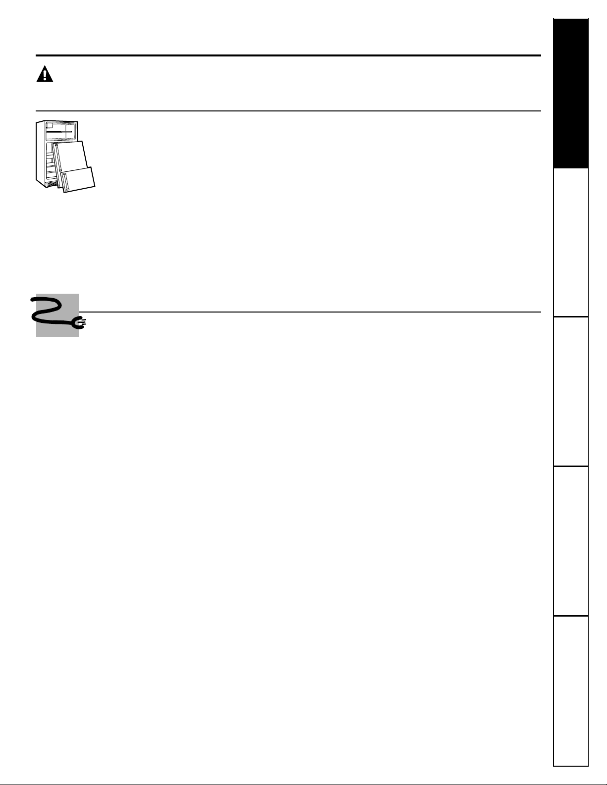
PROPER DISPOSAL OF THE REFRIGERATOR
Child entrapment and suffocation are not problems
of the past. Junked or abandoned refrigerators are
still dangerous…even if they will sit for “just a few
days.” If you are getting rid of your old refrigerator,
please follow the instructions below to help prevent
accidents.
Before You Throw Away Your Old Refrigerator
or Freezer:
■Take off the doors.
■Leave the shelves in place so that children may
not easily climb inside.
CFC Disposal
Your old refrigerator has a cooling system that used
CFCs (chlorofluorocarbons). CFCs are believed to
harm stratospheric ozone.
If you are throwing away your old refrigerator, make
sure the CFC refrigerant is removed for proper
disposal by a qualified servicer. If you intentionally
release this CFC refrigerant you can be subject to
fines and imprisonment under provisions of
environmental legislation.
USE OF EXTENSION CORDS
Because of potential safety hazards under certain conditions, we strongly recommend
against the use of an extension cord.
However, if you must use an extension cord, it is absolutely necessary that it be a UL-listed (in the United
States) or a CSA certified (in Canada), 3-wire grounding type appliance extension cord having a grounding
type plug and outlet and that the electrical rating of the cord be 15 amperes (minimum) and 120 volts.
DANGER! RISK OF CHILD ENTRAPMENT
3
Page 4
4
Consumer Support Troubleshooting Tips
Operating Instructions
Safety InstructionsInstallation InstructionsTroubleshooting Tips Installation Instructions Safety Instructions
Operating Instructions
IMPORTANT SAFETY INFORMATION.
READ ALL INSTRUCTIONS BEFORE USING.
WARNING!
HOW TO CONNECT ELECTRICITY
Do not, under any circumstances, cut or remove the third (ground) prong from the power cord.
For personal safety, this appliance must be properly grounded.
The power cord of this appliance is equipped
with a 3-prong (grounding) plug which mates
with a standard 3-prong (grounding) wall outlet
to minimize the possibility of electric shock hazard
from this appliance.
Have the wall outlet and circuit checked by a
qualified electrician to make sure the outlet is
properly grounded.
If the outlet is a standard 2-prong wall outlet,
it is your personal responsibility and obligation
to have it replaced with a properly grounded
3-prong wall outlet.
The refrigerator should always be plugged into its
own individual electrical outlet which has a voltage
rating that matches the rating plate.
This provides the best performance and also
prevents overloading house wiring circuits which
could cause a fire hazard from overheated wires.
Never unplug your refrigerator by pulling on the
power cord. Always grip plug firmly and pull
straight out from the outlet.
Repair or replace immediately all power cords that
have become frayed or otherwise damaged. Do not
use a cord that shows cracks or abrasion damage
along its length or at either end.
When moving the refrigerator away from the
wall, be careful not to roll over or damage the
power cord.
USE OF ADAPTER PLUGS
(Adapter plugs not permitted in Canada)
Because of potential safety hazards under certain conditions, we strongly recommend against the use of
an adapter plug.
However, if you must use an adapter, where local
codes permit, a
temporary connection
may be made
to a properly grounded 2-prong wall outlet by use
of a UL-listed adapter available at most local
hardware stores.
The larger slot in the adapter must be aligned with
the larger slot in the wall outlet to provide proper
polarity in the connection of the power cord.
When disconnecting the power cord from the
adapter, always hold the adapter in place with one
hand while pulling the power cord plug with the
other hand. If this is not done, the adapter ground
terminal is very likely to break with repeated use.
If the adapter ground terminal breaks,
DO NOT USE
the refrigerator until a proper ground has been
established.
Attaching the adapter ground terminal to a wall outlet
cover screw does not ground the appliance unless the
cover screw is metal, and not insulated, and the wall
outlet is grounded through the house wiring. You should
have the circuit checked by a qualified electrician to make
sure the outlet is properly grounded.
READ AND FOLLOW THIS SAFETY INFORMATION CAREFULLY.
SAVE THESE INSTRUCTIONS
Page 5
www.GEAppliances.com
Consumer SupportTroubleshooting Tips
Operating InstructionsSafety Instructions
Installation Instructions
About the controls on the refrigerator.
5
7
3
Freezer
5
4
6
Refrigerator
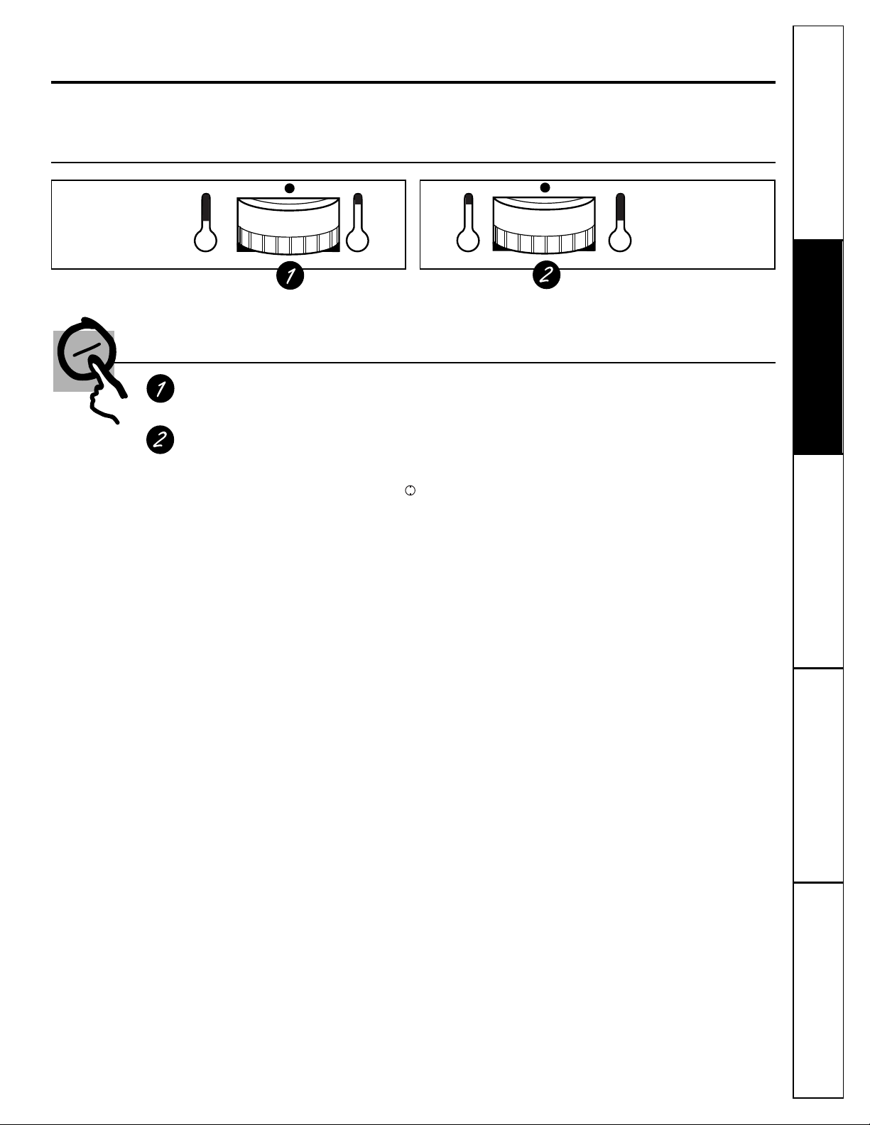
Control Settings
Freezer Control
The freezer control maintains the temperature in the freezer compartment.
Refrigerator Control
The refrigerator control maintains the temperature throughout the refrigerator compartment.
Moving the refrigerator control to
OFF
stops cooling in both areas— refrigerator and freezer—
but does not shut off power to the refrigerator.
After changing the controls, allow 24 hours for the refrigerator to reach the temperature you have set.
IMPORTANT!
When placing food packages in the refrigerator or freezer compartments, make sure that they
do not prevent the doors from fully closing. A partially open door will cause abnormally high
temperatures that may affect food preservation and will result in higher energy consumption.
Initially set the refrigerator and freezer controls at 5.
For refrigerator and freezer, 5 is normal, 9 is coldest.
Line up the setting with the dot.
If you want colder or warmer temperatures, adjust the
refrigerator temperature first. When satisfied with that
setting, adjust the freezer temperature.
5
Page 6
Consumer Support Troubleshooting Tips
Operating Instructions
Safety InstructionsInstallation InstructionsTroubleshooting Tips Installation Instructions Safety Instructions
Operating Instructions
Troubleshooting Tips Installation Instructions Safety Instructions
Operating Instructions
About the refrigerator shelves, bins and racks.
Not all features are on all models.
6
Bins on the Door
Bins can easily be rearranged or carried
from refrigerator to work area.
To remove:
Tilt the bin up and pull out on
the molded supports until it comes
completely out of the door.
To replace or relocate:
Select desired shelf
height, engage the bin in the molded
supports on the door and slide the bin in.
Bin will hook into place.
Fixed door shelf.
To install shelf, push it in,
then down to lock it in place.
The divider
helps prevent tipping, spilling or
sliding of small items stored on the door
shelf. Place a finger on either side of the
divider near the front and move it back and
forth to fit your needs.
Adjustable Bin
Fixed Door Shelf
Divider
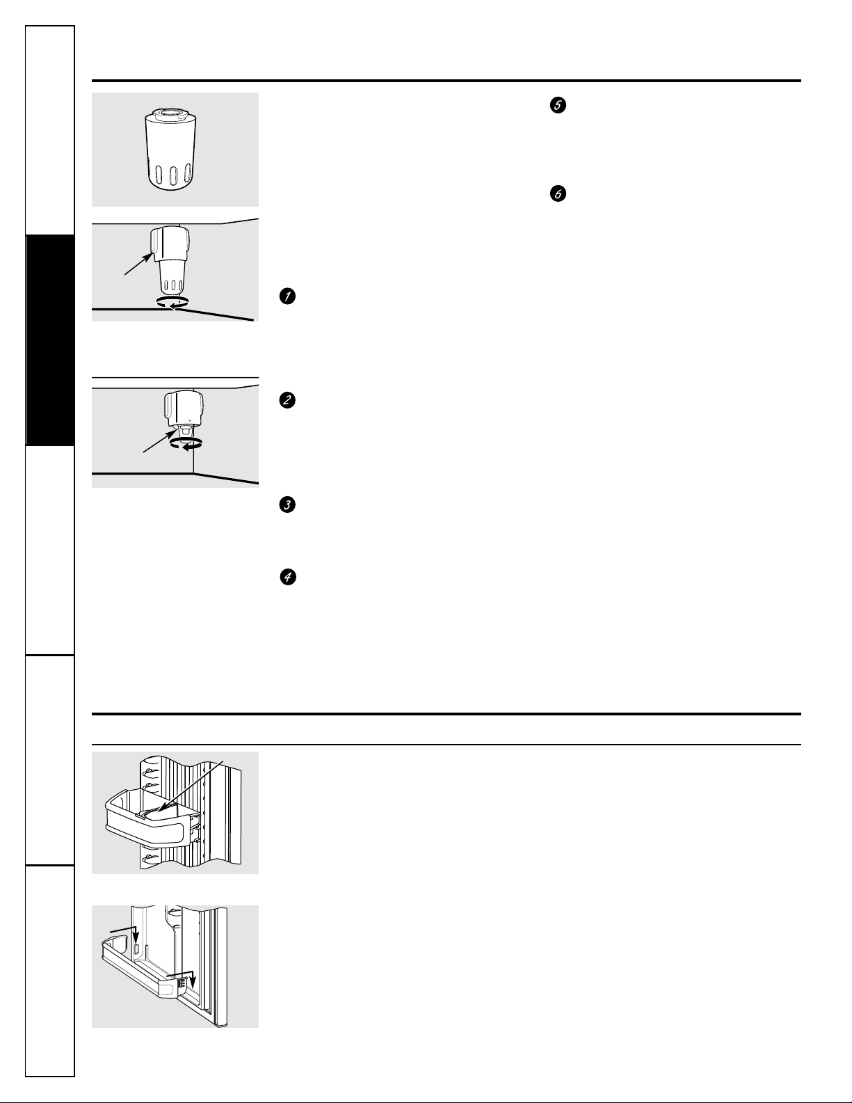
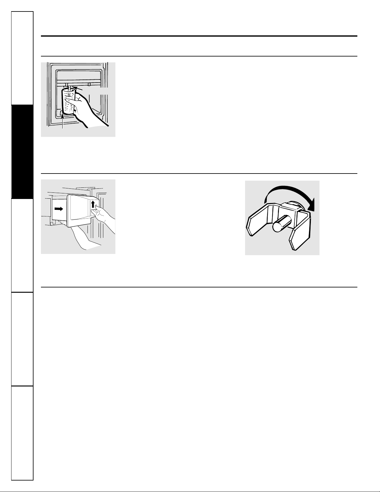
About the water filter.
Water Filter Cartridge
The water filter cartridge is located in the
back upper right corner of the refrigerator
compartment.
When to Replace the Filter
The water filter should be replaced every
6 months or earlier, depending on quantity
of use and water quality.
Installing the Filter Cartridge
If you are replacing the cartridge, first
remove the old one by slowly turning it
to the left.
Do not
pull down on the
cartridge. A small amount of water may
drip down. (Keep the filter bypass plug
in a safe place.)
Unpack the new filter. (Each new
refrigerator comes equipped with a
sample water filter that is taped to the
inside of the fresh food door.) Write on
the new filter the date (month/year)
when it was installed.
Fill the replacement cartridge with
water from the tap to allow for better
flow from the dispenser immediately
after installation.
Lining up the arrow on the cartridge
and the cartridge holder, place the
top of the new cartridge up inside
the holder.
Do not
push it up into
the holder.
Slowly turn it to the right until the filter
cartridge stops.
DO NOT OVERTIGHTEN.
As you turn the cartridge, it will
automatically raise itself into position.
Cartridge will rotate about 1/4 turn.
Run water from the dispenser for
3 minutes (about 11⁄2 gallons [6 liter])
to clear the system and prevent
sputtering.
NOTE:
A newly-installed water filter
cartridge may
cause water to spurt
from the dispenser.
Filter Bypass Plug
You must use the filter bypass plug
when a replacement filter cartridge is not
available. The dispenser and the icemaker
will not operate without the filter or filter
bypass plug.
Replacement Filters:
To order additional filter cartridges in
the United States, visit our Website,
www.GEAppliances.com, or call
GE Parts and Accessories, 800.626.2002.
GWF
Suggested Retail $34.95
Customers in Canada should consult
the yellow pages for the nearest Camco
Service Center, or visit our Website,
www.geappliances.ca.
Place the top of the cartridge up
inside the cartridge holder and
slowly turn it to the right.
Filter Bypass Plug
Cartridge
Holder
Page 7
www.GEAppliances.com
Consumer SupportTroubleshooting Tips
Operating InstructionsSafety Instructions
Installation Instructions
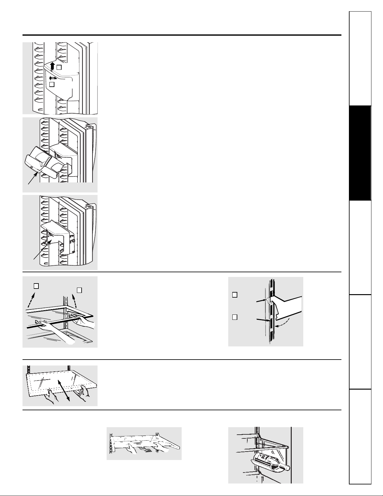
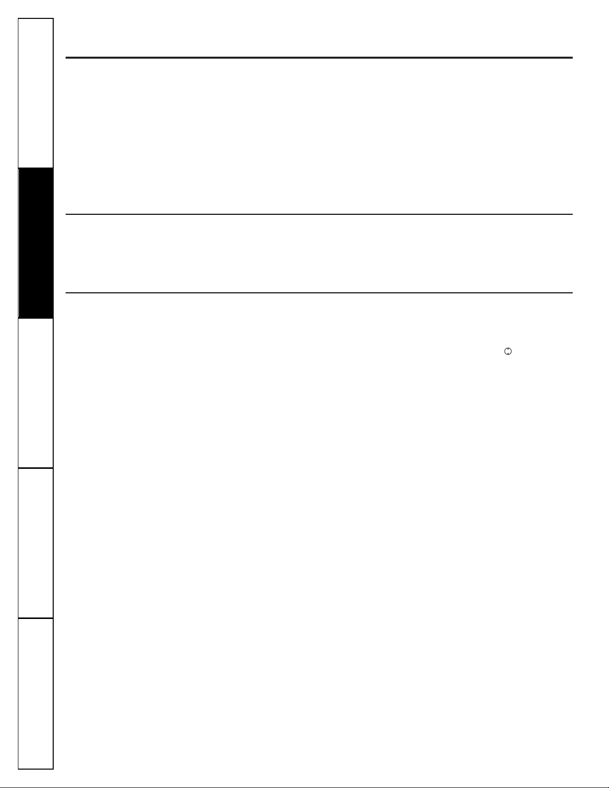
Slide-Out Spillproof Shelves
Spillproof shelves have special edges
to help prevent spills from dripping to
lower shelves. The shelves slide forward
and backward for ease of accessibility.
Rearranging the Shelves
Shelves in the fresh food and freezer
compartments are adjustable.
To Remove
To Replace
Lift up and out
2
Insert
top hook
1
Lower to
lock in place
2
Tilt up
1
Quick Space Shelf Removable Wine Rack
This shelf splits in half and slides under
itself for storage of tall items on the
shelf below.
7
Quick Store Bin
To avoid damaging the refrigerator, make sure the bin is closed and latched
before closing the refrigerator door.
This bin can be placed on the fresh food or freezer door.
To remove the bin,
push up on the thumb tab while lifting the bin up
and out of the housing.
To move,
lift the bin housing up and out of the supports on the door.
You do not have to remove the bin from the housing when moving it.
Pull forward
2
Push up
1
Quick Store Bin
Bin
Housing
Page 8
Consumer Support Troubleshooting Tips
Operating Instructions
Safety InstructionsInstallation InstructionsTroubleshooting Tips Installation Instructions Safety Instructions
Operating Instructions
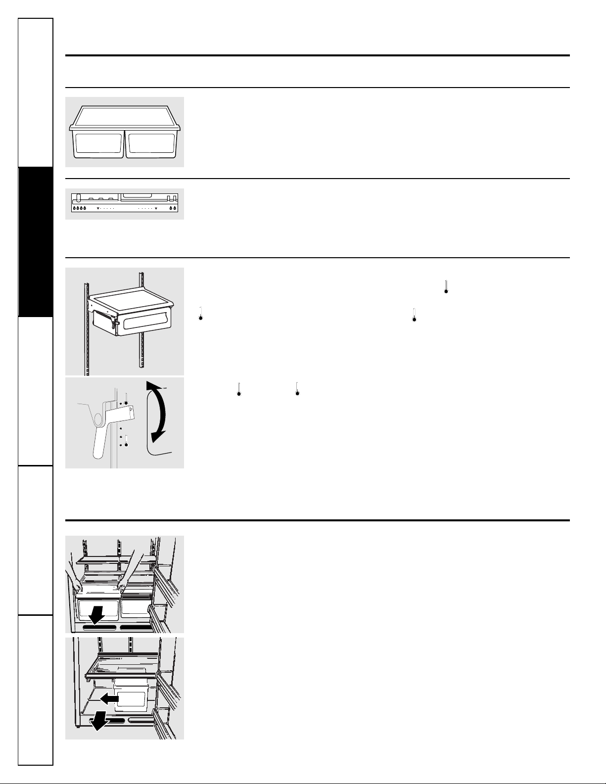
About crisper removal.
To remove:
These drawers can be removed easily
by lifting up slightly while pulling the
drawers forward past the
stop
location.
When the door cannot be fully opened,
remove the drawer farthest from the door
by pulling it straight out. Then slide the
other drawer toward the middle and
remove it.
8
When the pan is placed in the top 6 slots
on the left side and the lever is set at
(coldest), air from the freezer is forced
around the pan to keep it very cold.
You can move the pan to any location if you
don’t want the extra cold storage.
The settings can be adjusted anywhere
between (cold) and (coldest).
When set at (cold), the pan will stay at
the normal refrigerator temperature.
The (coldest) setting provides the
coldest storage area.
Adjustable Temperature Deli Pan
About the crispers and pans.
Not all features are on all models.
Fruit and Vegetable Crispers
Excess water that may accumulate in the
bottom of the drawers should be emptied
and the drawers wiped dry.
Adjustable Humidity Crispers
Slide the control all the way to the
Veg.
setting to provide high humidity
recommended for most vegetables.
Slide the control all the way to the
Fruit
setting to provide lower humidity levels
recommended for most fruits.
Crisper Removal
Veg.
Humidity
Fruit
Page 9
Consumer SupportTroubleshooting Tips
Operating InstructionsSafety Instructions
Installation Instructions
Icemaker Accessory Kit
If your refrigerator did not come already
equipped with an automatic icemaker,
an icemaker accessory kit (IM-4) is available
at extra cost.
Follow instructions in the installation
manual that is included in the kit.
P
9
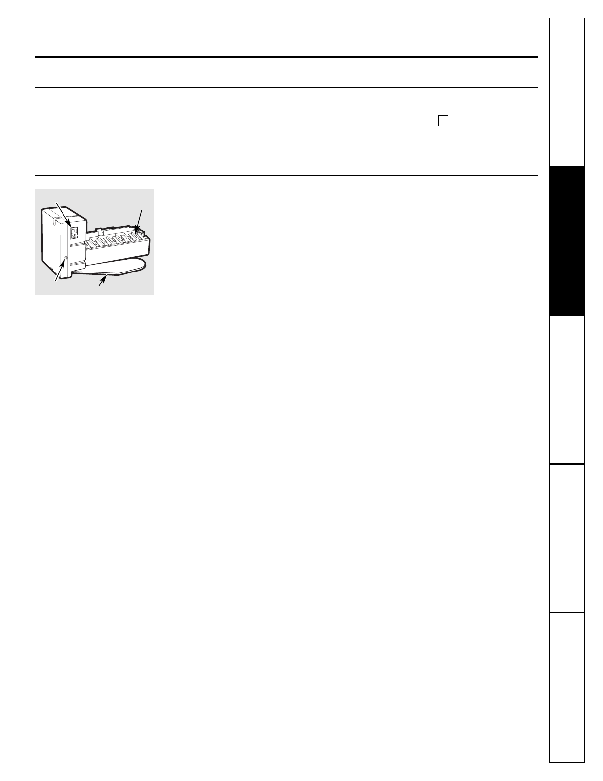
Automatic Icemaker
(on some models)
The icemaker will produce seven cubes
per cycle—approximately 100–130 cubes
in a 24-hour period, depending on freezer
compartment temperature, room
temperature, number of door openings
and other use conditions.
If the refrigerator is operated before the
water connection is made to the icemaker,
set the power switch to
O (off)
.
When the refrigerator has been connected
to the water supply, set the power switch to
I (on)
. The green light will come on.
The icemaker will fill with water when it
cools to 15°F (-10°C). A newly-installed
refrigerator may take 12 to 24 hours to
begin making ice cubes.
Throw away the first few batches of ice to
allow the water line to clear.
Be sure nothing interferes with the sweep
of the feeler arm.
When the bin fills to the level of the feeler
arm, the icemaker will stop producing ice.
It is normal for several cubes to be joined
together.
If ice is not used frequently, old ice cubes
will become cloudy, taste stale and shrink.
If ice cubes get stuck in the icemaker, the
green power light will blink. To correct this,
set the power switch to
O (off)
and remove
the cubes. Set the power switch to
I (on)
to
restart the icemaker.
After the icemaker has been turned on
again, there will be a delay of about
45 minutes before the icemaker resumes
operations.
NOTE: In homes with lower-than-average water
pressure, you may hear the icemaker cycle multiple
times when making one batch of ice.
About the automatic icemaker.
A newly-installed refrigerator may take 12–24 hours to begin making ice.
Icemaker
Feeler Arm
Power Switch
Green
Power Light
www.GEAppliances.com
Page 10
Consumer Support Troubleshooting Tips
Operating Instructions
Safety InstructionsInstallation InstructionsTroubleshooting Tips Installation Instructions Safety Instructions
Operating Instructions
10
About the ice and water dispenser.
On some models
To Use the Dispenser
Select
CUBES, CRUSHED ICE
or
WATER.
Press the rim of the glass gently against
the dispenser pad.
If no water is dispensed when the refrigerator
is first installed, there may be air in the water
line system. Press the dispenser pad for at least
2 minutes to remove trapped air from the water
line and to fill the system with water. To flush
out impurities in the water line, throw away the
first six glassfuls of water.
The spill shelf is not self-draining.
To reduce water spotting, the shelf and
its grille should be cleaned regularly.
A light switch turns the
night light
in the
dispenser on or off. The light also comes on
when the dispenser pad is pressed. The light
in the dispenser should be replaced with a
7-watt maximum bulb when it burns out.
CAUTION: Never put fingers or any other
objects into the ice crusher discharge
opening.
Spill Shelf
Dispenser Pad
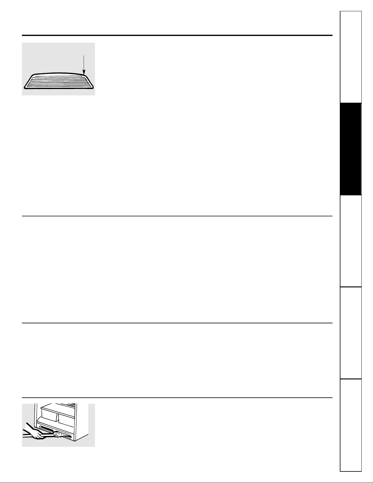
Dispenser Ice Storage Bin
To remove:
Lift the handle to free the bin from the
shelf and pull the bin straight out while
supporting it at front and rear.
To replace:
Slide the bin back until it clicks into place.
If the bin does not go all the way back,
remove it and rotate the drive mechanism
1/4 turn. Then push the bin back again.
Rotate
Drive
Mechanism
Important Facts About Your Dispenser
■Add ice before filling the glass with a
beverage. This will prevent splashing.
■Do not add ice from trays or bags to
the storage bin. It may not crush or
dispense well.
■Avoid overfilling a glass with ice or using
narrow or extra-tall glasses. Backed-up ice
can jam the chute or cause the door in
the chute to freeze shut. If ice is blocking
the chute, poke it through with a
wooden spoon.
■Beverages and foods should not be
quick-chilled in the ice storage bin. Cans,
bottles or food packages in the storage
bin may cause the dispenser to jam.
■Some crushed ice may be dispensed
even though you selected
CUBES.
This
happens occasionally when a few cubes
accidentally get directed to the crusher.
■After crushed ice is dispensed, some
water may drip from the chute.
■Sometimes a mound of snow will form
on the door in the ice chute. This
condition is normal and usually occurs
when you have dispensed crushed ice
repeatedly. The snow will eventually
evaporate.
■Dispensed water is not ice cold. For
colder water, simply add crushed ice or
cubes before dispensing water.
Page 11
Cleaning the Inside
To help prevent odors,
leave an open box of
baking soda in the fresh food and freezer
compartments.
Unplug the refrigerator before cleaning.
If this
is not practical, wring excess moisture out
of sponge or cloth when cleaning around
switches, lights or controls.
Use warm water and baking soda solution—
about a tablespoon (15 ml) of baking soda
to a quart (1 liter) of water. This both cleans
and neutralizes odors. Rinse and wipe dry.
After cleaning the door gaskets, apply a thin
layer of paraffin wax to the door gaskets at
the hinge side. This helps keep the gaskets
from sticking and bending out of shape.
Avoid cleaning cold glass shelves with hot
water because the extreme temperature
difference may cause them to break. Handle
glass shelves carefully. Bumping tempered glass
can cause it to shatter.
Do not wash any plastic refrigerator parts in the
dishwasher.
Behind the Refrigerator
Be careful when moving the refrigerator
away from the wall. All types of floor
coverings can be damaged, particularly
cushioned coverings and those with
embossed surfaces.
Pull the refrigerator straight out and return
it to position by pushing it straight in.
Moving the refrigerator in a side direction
may result in damage to the floor covering
or refrigerator.
When pushing the refrigerator back, make sure
you don’t roll over the power cord or icemaker
supply line (on some models).
Condenser
There is no need for routine condenser
cleanings in normal home operating
environments. However, in environments
that may be particularly dusty or greasy, the
condenser should be cleaned periodically
for efficient refrigerator operation.
Cleaning the condenser:
Sweep away or vacuum up dust.
For best results, use a brush specially
designed for this purpose. It is available at
most appliance parts stores.
www.GEAppliances.com
Consumer SupportTroubleshooting Tips
Operating InstructionsSafety Instructions
Installation Instructions
11
Care and cleaning of the refrigerator.
Cleaning the Outside
The dispenser spill shelf
(on some models),
should be wiped dry because it is not selfdraining. Water left under the grille may
leave deposits. Remove the deposits by
adding undiluted vinegar. Let it soak until
the deposits disappear or become loose
enough to rinse away.
The dispenser pad
(on some models).
Clean with warm water and baking soda
solution—about a tablespoon (15 ml)
of baking soda to a quart (1 liter) of water.
Rinse thoroughly and wipe dry.
HINT: Open the freezer door part way to prevent
dispensing of ice or water when cleaning.
The door handles and trim.
Clean with
a cloth dampened with soapy water.
Dry with a soft cloth.
Keep the outside clean.
Wipe with a clean
cloth lightly dampened with kitchen
appliance wax or mild liquid dish detergent.
Dry and polish with a clean, soft cloth.
The stainless steel panels and door handles
(on some models) can be cleaned with a
commercially available stainless steel
cleaner such as
Stainless Steel Magic™
.
Stainless Steel Magic™
is available at Ace,
True Value, Servistar, HWI and other
leading stores.
It can also be ordered by visiting our
Website, www.GEAppliances.com, or call
GE Parts and Accessories, 800.626.2002.
Order part number WX10X15.
Do not use appliance wax or polish on the
stainless steel.
Do not wipe the refrigerator with a soiled dish
cloth or wet towel. These may leave a residue
that can erode the paint. Do not use scouring
pads, powdered cleaners, bleach or cleaners
containing bleach because these products can
scratch and weaken the paint finish.
Press here to
remove grille.
Page 12
12
Care and cleaning of the refrigerator.
Preparing for Vacation
For long vacations or absences, remove
food and unplug the refrigerator. Clean
the interior with a baking soda solution
of one tablespoon (15 ml) of baking soda
to one quart (1 liter) of water. Leave the
doors open.
On automatic icemaker models,
set the
icemaker power switch to
0 (off)
and shut
off the water supply to the refrigerator.
If the temperature can drop below freezing,
have a qualified servicer drain the water
supply system (on some models) to prevent
serious property damage due to flooding.
Preparing to Move
Secure all loose items such as grille, shelves
and drawers by taping them securely in
place to prevent damage.
Be sure the refrigerator stays in an upright
position during moving.
Lightbulb Replacement
To replace a burned-out bulb, unplug
the refrigerator from its electrical outlet,
unscrew the bulb when cool and replace
it with an appliance bulb of the same or
lower wattage.
When changing the freezer light, first
remove the light shield.
Turning the control to the OFF position does
not remove power to the light circuit.
Consumer Support Troubleshooting Tips
Operating Instructions
Safety InstructionsInstallation InstructionsTroubleshooting Tips Installation Instructions Safety Instructions
Operating Instructions
Page 13
Consumer SupportTroubleshooting Tips
Operating InstructionsSafety Instructions
Installation Instructions
13
Trim kits and decorator panels.
For CustomStyle™ models
Read these instructions completely and carefully.
Before You Begin
Some models are equipped with trim kits that allow you to install door panels. You can order pre-cut
black or white acrylic decorator panels or stainless steel panels from GE Parts and Accessories,
800.626.2002, or visit our Website, www.GEAppliances.com. In Canada call 1.888.261.3055 or visit our
Website, www.geappliances.ca. Or you can add wood panels to match your kitchen cabinets.
Panels less than 1/4″(6 mm) thick
When installing wood panels less than 1/4″ (6 mm) thick, you need to create a filler panel, such as
1/8″ (3 mm) cardboard, that will fit between the face of the door and the wood panel. If you are installing
the pre-cut decorator panels, pre-cut filler panels are included in the kit. The combined thickness of the
decorator or wood panel and the filler panel should be 1/4″ (6 mm).
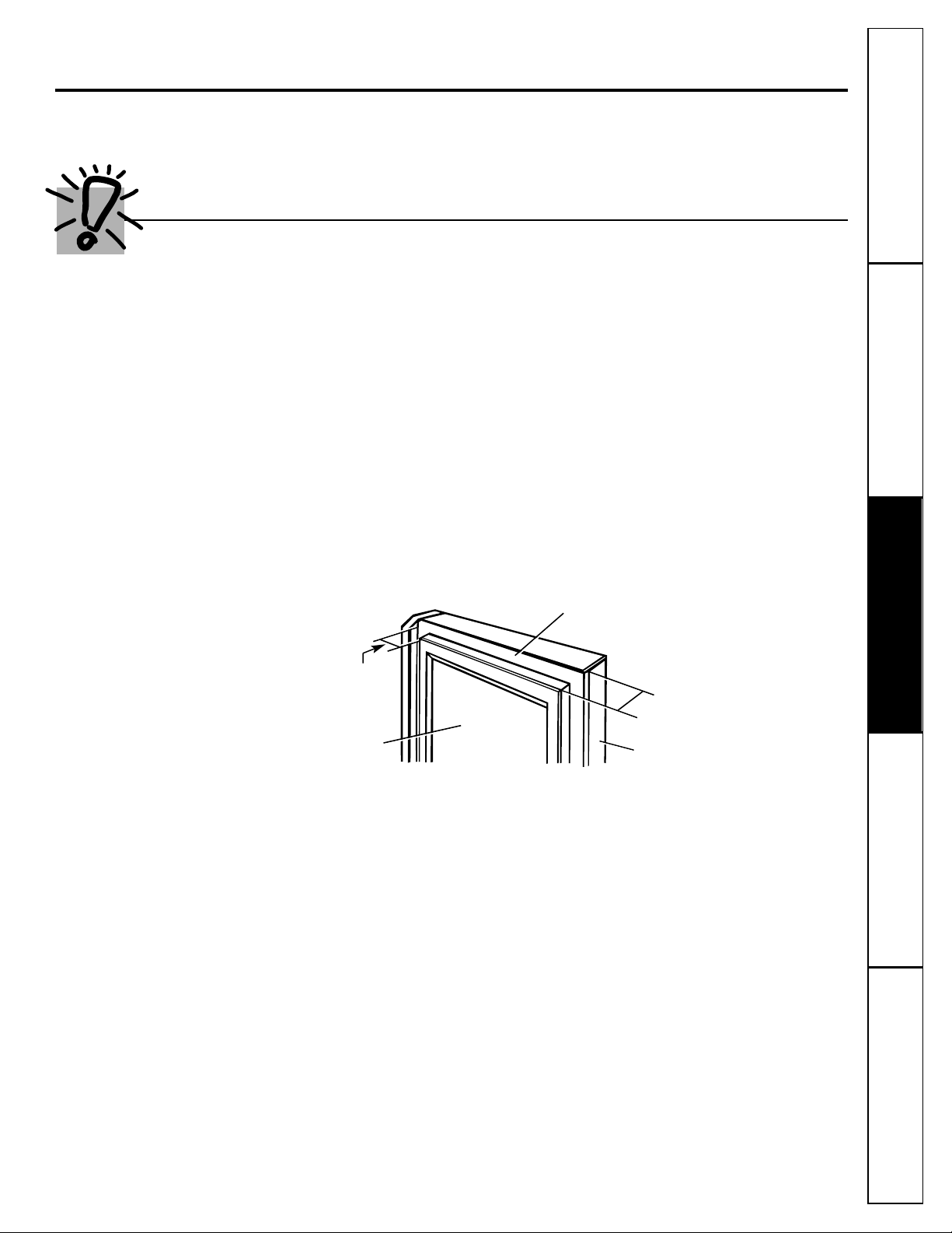
3/4″ (19 mm) or Raised Panel
A raised panel design screwed or glued to a 1/4″ (6 mm) thick backing, or a 3/4″ (19 mm) routed
board can be used. The raised portion of the panel must be fabricated to permit clearances of at least
2
5
⁄8″ (67 mm) from the handle side for fingertip clearance.
Weight limitations for custom panels:
Fresh Food 38 lb. (17 kg) max.
Freezer Door 22 lb. (10 kg) max.
2
5
⁄8″(67 mm)
Clearance
Handle Side
Appearance
Panel
Refrigerator
Door
1/4″(6 mm)
Thick Backing
3/4″
(19 mm)
Page 14
14
Consumer Support Troubleshooting Tips
Operating Instructions
Safety InstructionsInstallation InstructionsTroubleshooting Tips Installation Instructions Safety Instructions
Operating Instructions
Trim kits.
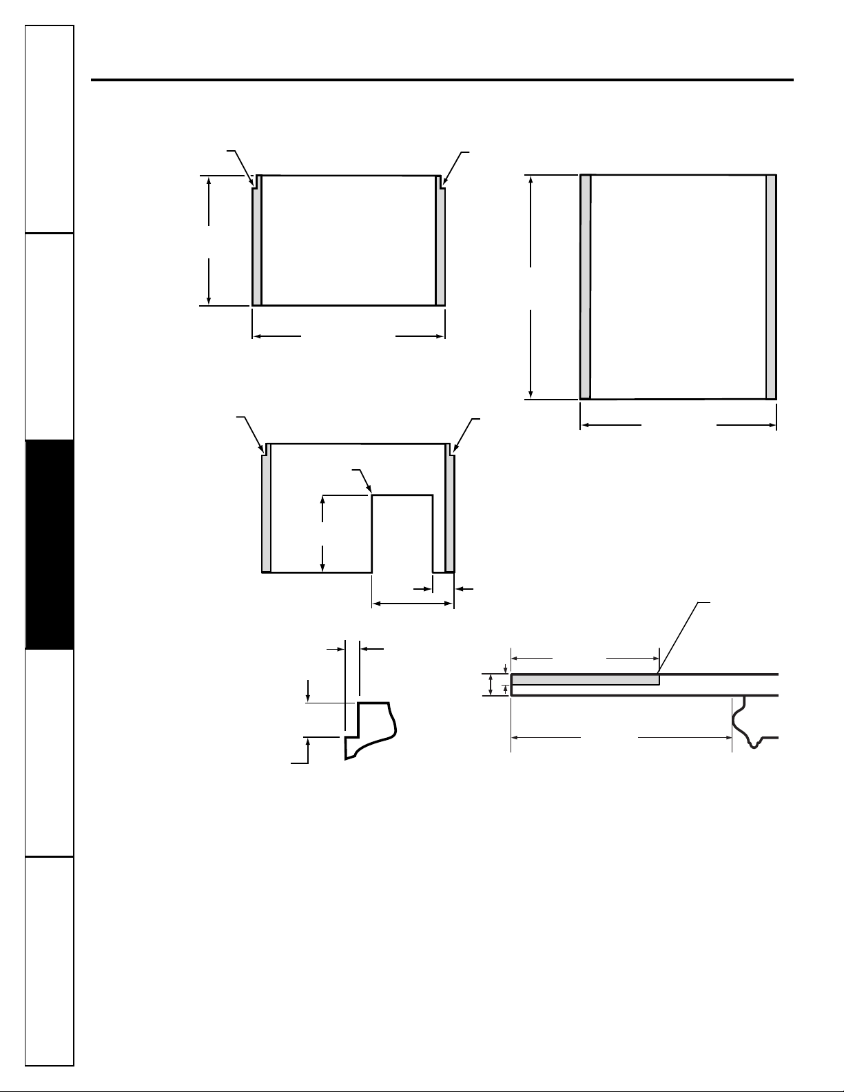
Dimensions for Custom Wood Panels
■The areas at the top of the freezer panels need to be cut out of the panels.
■The shaded areas indicate areas that must be routed out by 1/8″ (3 mm) on the backside
(handle side only) of the 1/4″ (6 mm) panel. For panels less than 1/8″ (3 mm) thick, these
areas can be cut out of the filler panels.
Cut-Out
Cut-Out
Cut-Out
24
1
/16″
(61.1 cm)
3/8″(10 mm)
35
3
/4″(90.8 cm)
14
7
/8″(37.8 cm)
15
7
/16″(39.2 cm)
1/8″(3 mm)
5/16″(8 mm)
Freezer Panel
Corner Cut-Out
3
15
/16″(10.1 cm)
1
3
/4″(4.4 cm)
Back of Panel
2
5
/8″(6.5 cm)
Fingertip Clearance
Area to be routed
on back handle
side to allow for
mounting screws
42
1
/4″
(107.3 cm)
35
3
/4″(90.8 cm)
Cut-Out
Freezer Panel
Without Dispenser
Freezer Panel
With Dispenser
Refrigerator Panel
FRONT
Front of
Panel
1
/4″
(6 mm)
1
/8″
(3 mm)
Top View–Handle Side
Page 15
Cut out
Cut out
Top Trim
Screw Holes
Blue
Tape Liner
Blue
Tape Liner
Refrigerator
Panel
Freezer
Panel
Side Trim
Freezer
Side Trim
Refrigerator
Consumer SupportTroubleshooting Tips
Operating InstructionsSafety Instructions
Installation Instructions
15
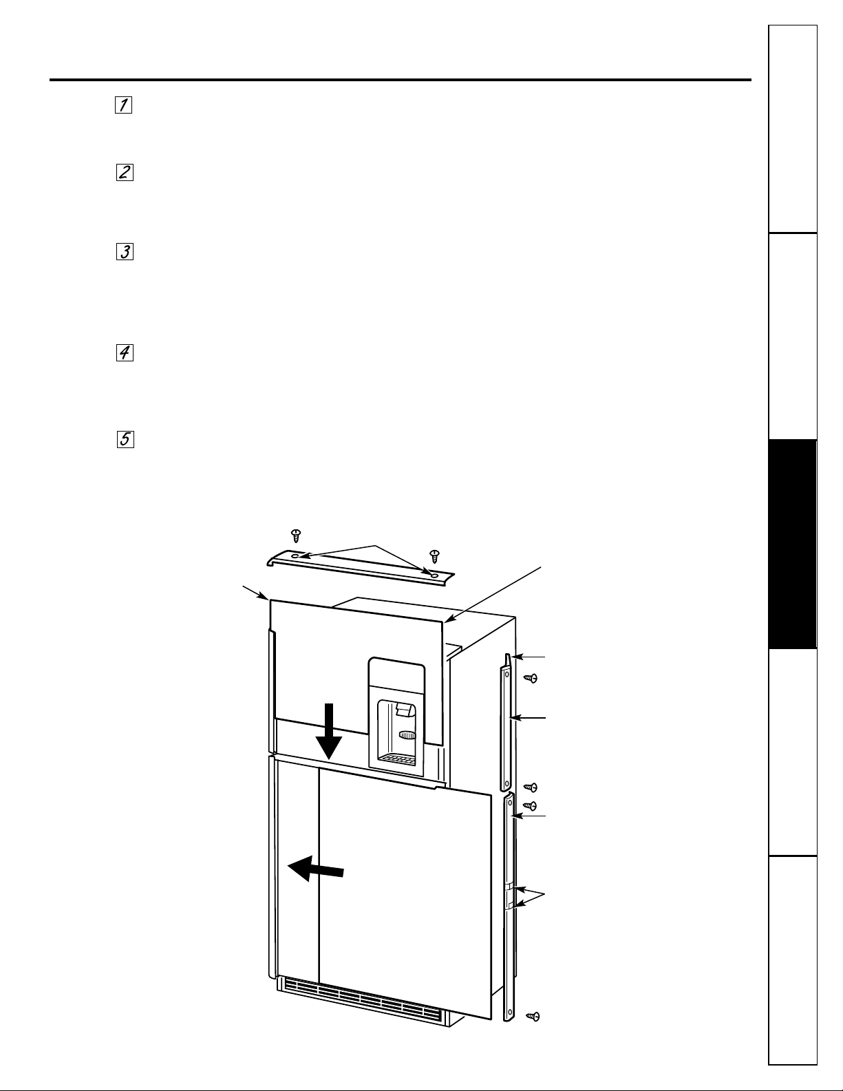
Inserting the door panels.
Remove the Top Trim on the Freezer Door
Using a T-20 Torx Driver, remove the two screws attaching the Top Trim.
Insert the Freezer Door Panel
Lower the freezer panel until it slides into the slot behind the door panel.
Push the filler panel (required with some door panels) in behind the
decorator panel.
Reinstall the Top Trim on the Freezer Door
Using a T-20 Torx Driver, reinstall the two screws attaching the Top Trim.
Tighten two screws to 30 in-lbs torque.
Carefully push the panel in until it slides into the slot behind the door
handle. Push the filler panel (required with some door panels) in behind
the decorator panel.
Insert the Refrigerator Panel
Remove the Side Trim
Using a Phillips screwdriver, remove the four screws attaching the Side Trim
to the refrigerator and freezer doors (2 screws on each door).
Page 16
16
Inserting the door panels.
Install the Freezer Door Side Trim
Do not remove the protective film on the outside
of the Side Trim until the Side Trim is installed.
Fit the top of the freezer door Side Trim under the
corner of the Top Trim and fit the bottom of the
Side Trim over the Bottom Trim as illustrated.
Attach the Side Trim to the door using the two
screws removed in Step 2. Make sure the Side trim
is fitting correctly and that you are satisfied with
the appearance of all parts before pulling the
blue tape liner.
Holding the trim in place with one hand, gradually
pull the blue tape liner out, perpendicular to the
trim. Pull about 3″ (80 mm) out at a time, pressing
the trim with your hand as the adhesive is exposed.
Install the Refrigerator Door Side Trim
Fit the Side Trim over the ends of the refrigerator
door Top and Bottom Trim as illustrated. Attach
the Side Trim to the door using the two screws
removed in Step 2. Make sure the Side Trim is
fitting correctly and that you are satisfied with
the appearance of all parts before pulling the
two pieces of blue tape liner.
Pull the top blue tape liner up about 3″ (80 mm),
pressing the trim with your hand as the adhesive is
exposed to the door. Then pull the bottom blue
tape liner down about 3″ (80 mm). Follow the tape
with your hand, pressing the trim adhesive against
the door.
Continue pulling the blue tape liner loose,
alternating between the top and bottom and
pressing the Side Trim against the door.
Remove the Protective Film From the Outside of the Side Trim
Consumer Support Troubleshooting Tips
Operating Instructions
Safety InstructionsInstallation InstructionsTroubleshooting Tips Installation Instructions Safety Instructions
Operating Instructions
Page 17
17
BEFORE YOU BEGIN
Read these instructions completely and carefully.
•
IMPORTANT
–
Save these
instructions for local inspector’s use.
•
IMPORTANT
–
Observe all
governing codes and ordinances.
• Note to Installer –Be sure to leave these
instructions with the Consumer.
• Note to Consumer –Keep these instructions
for future reference.
• Skill level – Installation of this appliance requires
basic mechanical skills.
• Completion time – Refrigerator Installation
15 minutes
• Proper installation is the responsibility of the
installer.
• Product failure due to improper installation is not
covered under the Warranty.
• Do not install the refrigerator where the temperature
will go below 60°F (16°C) because it will not run often
enough to maintain proper temperatures.
• Do not install the refrigerator where the temperature
will go above 100°F (37°C) because it will not perform
properly.
• Install the refrigerator on a floor strong enough to
support it when fully loaded.
REFRIGERATOR LOCATION
Installation
Refrigerator
Instructions
Profile
Model 22
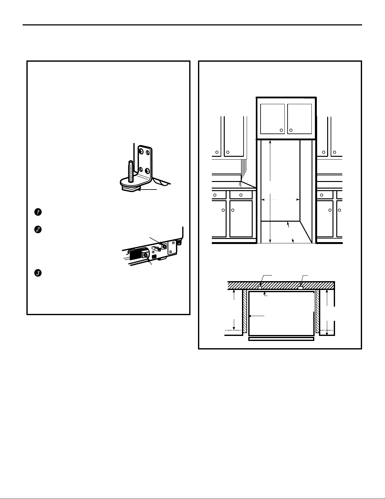
Allow the following clearances for ease of installation,
proper air circulation and plumbing and electrical
connections:
• Sides 1/8″ (3 mm)
• Top 1″ (25 mm)
• Back 1/2″ (13 mm)
If the refrigerator is against a wall on either side, allow a
1/8″ (3 mm) door clearance.
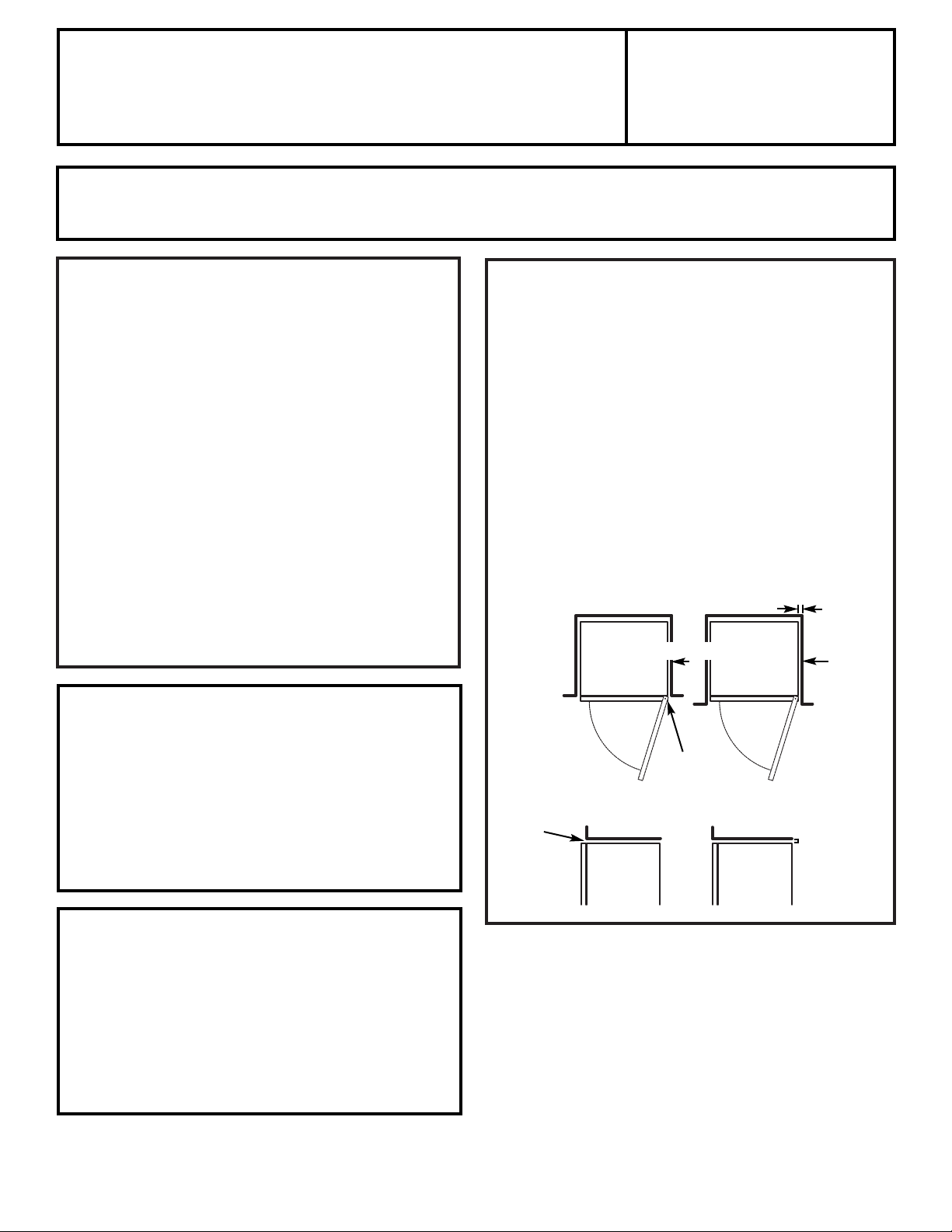
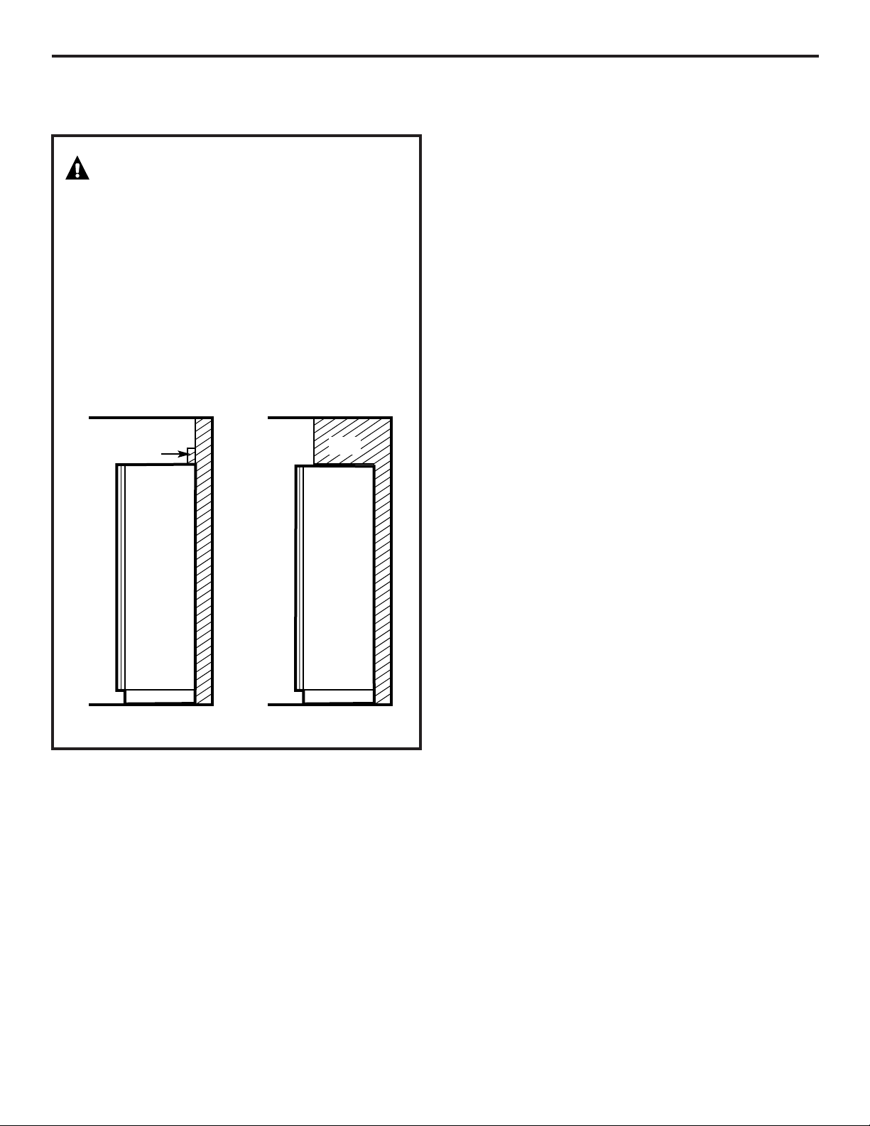
When using the trim kit:
If the cabinet is not flush with the enclosure or is
recessed, allow an additional clearance of 1/2″ (13 mm)
on the door hinge side and at the top. Ensure proper
door opening:
CLEARANCES
If the refrigerator has an icemaker, it will have to be
connected to a cold water line. A GE water supply kit
(containing tubing, shutoff valve, fittings and
instructions) is available at extra cost from your dealer,
by visiting our Website at www.GEAppliances.com (in
Canada at www.geappliances.ca) or from Parts and
Accessories, 800.626.2002 (in Canada 1.888.261.3055).
WATER SUPPLY TO THE ICEMAKER
(ON SOME MODELS)
Questions? Call 800.GE.CARES (800.432.2737)
or Visit our Website at:
www.GEAppliances.com
In Canada, call 1.800.361.3400
or Visit our Website at:
www.geappliances.ca
Preferred
Allow Additional
Clearance
Top of Cabinet
Top of Cabinet
Enclosure
Enclosure
Flush
Enclosure Enclosure
1
1
⁄2″(38 mm)
Flush
with
Cabinet
Door
Door
5/8″
(16 mm)
Page 18
Installation Instructions
18
BEFORE YOU BEGIN
The rollers have 2 purposes:
■ The rollers are used to level the refrigerator.
NOTE: The refrigerator must be completely level
for the icemaker to work.
■ Rollers allow you to move the refrigerator away from
the wall for cleaning.
■ Upon completion of leveling, adjust stability leg to
touch the floor.
To adjust the rollers:
Remove the base grille by pulling it out at the bottom.
Turn the two front roller
adjusting screws clockwise
to raise the refrigerator,
counterclockwise to lower it.
Use a 3/8″ socket wrench,
adjustable wrench or pliers.
CustomStyle™ models also
have rear adjustable rollers
so you can align the refrigerator with your kitchen
cabinets. Use a 5/16″ socket wrench to turn the
screws for the rear rollers—clockwise to raise it,
counterclockwise to lower it.
ROLLERS
Stability Leg
Front Roller
Adjusting Screw
Rear Roller
Adjusting Screw
DIMENSIONS AND SPECIFICATIONS
(for CustomStyle™ models)
70
1
/4″
(178.4 cm)
24
1
/2″
(62.2 cm)
36
1
/8″
(91.8 cm)
24
1
/2″(62.2 cm)
Side Panels
Electrical
Water
3/4″(19 mm) Airspace
(1/2″[8 mm] Gap +
1/4″[6 mm] Wall Plates)
25″(63.5 cm)
Countertop
24″
(61 cm)
Cabinet
Page 19
Installation Instructions
19
WARNING!
Stability Precaution for Models with Door
Trim Kit
The refrigerator is much heavier with decorator door
panels. To prevent the refrigerator from tipping over, you
must do one of the following:
• Install the refrigerator in an alcove or wall recess with
a soffit height of 70
1
/4″(178.4 cm).
• Install a 2″ (5.1 cm) x 4″ (10 cm) wood block, the full
width of the refrigerator. Secure the block with a
minimum of three (3) wood screws penetrating at least
3/4″ (19 mm) into wall studs.
Block
Soffit
Side ViewSide View
Page 20
20
Installation Instructions
Recommended copper water supply kits are WX8X2,
WX8X3 or WX8X4, depending on the amount of
tubing you need. Approved plastic water supply lines
are GE SmartConnect™ Refrigerator Tubing
(WX08X10002, WX08X10006, WX08X10015 and
WX08X10025).
When connecting your refrigerator to a GE Reverse
Osmosis Water System, the only approved installation
is with a GE RVKit. For other reverse osmosis water
systems, follow the manufacturer’s recommendations.
This water line installation is not warranted by the
refrigerator or icemaker manufacturer. Follow these
instructions carefully to minimize the risk of expensive
water damage.
Water hammer (water banging in the pipes) in house
plumbing can cause damage to refrigerator parts and
lead to water leakage or flooding. Call a qualified
plumber to correct water hammer before installing
the water supply line to the refrigerator.
To prevent burns and product damage, do not hook
up the water line to the hot water line.
If you use your refrigerator before connecting the
water line, make sure the icemaker power switch is
in the
O (off)
position.
Do not install the icemaker tubing in areas where
temperatures fall below freezing.
When using any electrical device (such as a power
drill) during installation, be sure the device is double
insulated or grounded in a manner to prevent the
hazard of electric shock, or is battery powered.
All installations must be in accordance with local
plumbing code requirements.
BEFORE YOU BEGIN
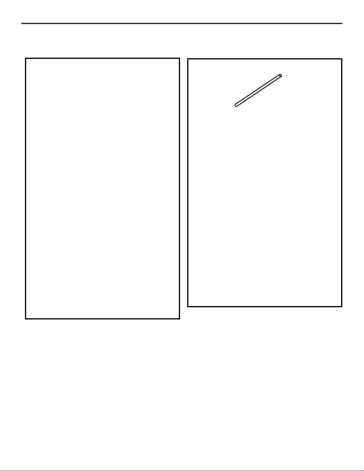
WHAT YOU WILL NEED
• Copper or GE SmartConnect™ Refrigerator Tubing
kit, 1/4″ outer diameter to connect the refrigerator
to the water supply. If using copper, be sure both ends
of the tubing are cut square.
To determine how much tubing you need: measure
the distance from the water valve on the back of the
refrigerator to the water supply pipe. Then add 8 feet
(2.4 m). Be sure there is sufficient extra tubing (about
8 feet [2.4 m] coiled into 3 turns of about 10 inches
[25 cm] diameter) to allow the refrigerator to move
out from the wall after installation.
GE SmartConnect™ Refrigerator Tubing Kits are
available in the following lengths:
2′ (.6 m) – WX08X10002
6′ (1.8 m) – WX08X10006
15′ (4.6 m) – WX08X10015
25′ (7.6 m) – WX08X10025
Be sure that the kit you select allows at least 8 feet
(2.4 m) as described above.
NOTE: The only GE approved plastic tubing is that
supplied in GE SmartConnect™ Refrigerator Tubing
kits. Do not use any other plastic water supply line
because the line is under pressure at all times. Certain
types of plastic will crack or rupture with age and cause
water damage to your home.
INSTALLING THE WATER LINE
(ON SOME MODELS)
Page 21
21
Installation Instructions
• A GE water supply kit (containing tubing, shutoff
valve and fittings listed below) is available at extra
cost from your dealer or from Parts and Accessories,
800.626.2002 (in Canada 1.888.261.3055).
• A cold water supply. The water pressure must be
between 20 and 120 p.s.i. (1.4–8.1 bar).
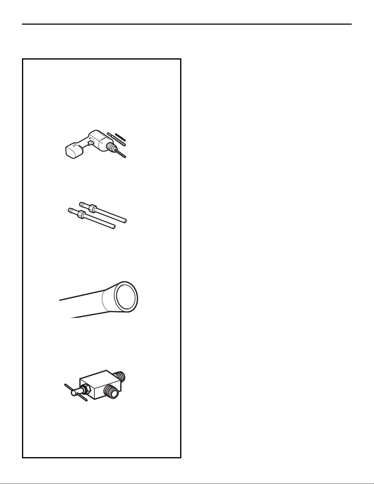
• Power drill.
• 1/2″ or adjustable wrench.
• Straight and Phillips blade screwdriver.
• Two 1/4″ outer diameter compression nuts and
2 ferrules (sleeves)—to connect the copper tubing
to the shutoff valve and the refrigerator water valve.
OR
• If you are using a GE SmartConnect™ Refrigerator
Tubing kit, the necessary fittings are preassembled
to the tubing.
• If your existing copper water line has a flared fitting
at the end, you will need an adapter (available at
plumbing supply stores) to connect the water line to
the refrigerator OR you can cut off the flared fitting
with a tube cutter and then use a compression fitting.
Do not cut formed end from GE SmartConnect™
Refrigerator tubing.
• Shutoff valve to connect to the cold water line.
The shutoff valve should have a water inlet with a
minimum inside diameter of 5/32″ at the point of
connection to the COLD WATER LINE. Saddle-type
shutoff valves are included in many water supply kits.
Before purchasing, make sure a saddle-type valve
complies with your local plumbing codes.
WHAT YOU WILL NEED (CONT.)
Page 22
22
Fasten the shutoff valve to the cold water pipe with
the pipe clamp.
NOTE: Commonwealth of Massachusetts Plumbing
Codes 248CMR shall be adhered to. Saddle valves
are illegal and use is not permitted in Massachusetts.
Consult with your licensed plumber.
Installation Instructions
SHUT OFF THE MAIN WATER
SUPPLY
Turn on the nearest faucet long enough to clear
the line of water.
Install the shutoff valve on the nearest frequently used
drinking water line.
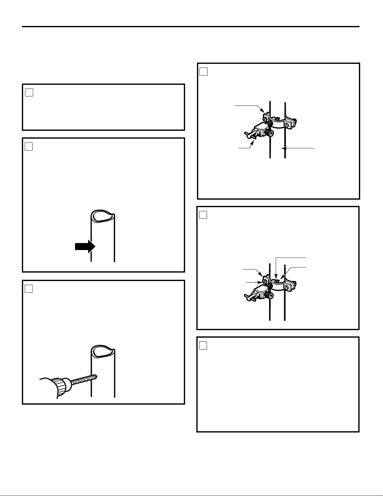
1
Choose a location for the valve that is easily
accessible. It is best to connect into the side of a
vertical water pipe. When it is necessary to connect
into a horizontal water pipe, make the connection
to the top or side, rather than at the bottom,
to avoid drawing off any sediment from the
water pipe.
CHOOSE THE VALVE LOCATION
2
Drill a 1/4″ hole in the water pipe (even if using a
self-piercing valve) using a sharp bit. Remove any
burrs resulting from drilling the hole in the pipe.
Take care not to allow water to drain into the drill.
Failure to drill a 1/4″ hole may result in reduced
ice production or smaller cubes.
DRILL THE HOLE FOR THE VALVE
3
FASTEN THE SHUTOFF VALVE
4
Tighten the clamp screws until the sealing washer
begins to swell.
NOTE: Do not overtighten or you may crush the
tubing.
TIGHTEN THE PIPE CLAMP
5
Vertical Cold
Water Pipe
Saddle-Type
Shutoff Valve
Washer
Inlet End
Pipe Clamp
Clamp Screw
Route the tubing between the cold water line and
the refrigerator.
Route the tubing through a hole drilled in the wall
or floor (behind the refrigerator or adjacent base
cabinet) as close to the wall as possible.
NOTE: Be sure there is sufficient extra tubing
(about 8 feet [2.4 m] coiled into 3 turns of about
10″ [25 cm] diameter) to allow the refrigerator to
move out from the wall after installation
.
ROUTE THE TUBING
6
Pipe Clamp
INSTALLING THE WATER LINE (CONT.)
Page 23
NOTES:
• Before making the connection to the refrigerator,
be sure the refrigerator power cord is not
plugged into the wall outlet.
• We recommend installing a water filter if your
water supply has sand or particles that could clog
the screen of the refrigerator’s water valve. Install
it in the water line near the refrigerator. If using
GE SmartConnect Refrigerator Tubing kit, you
will need an additional tube (WX08X10002) to
connect the filter. Do not cut plastic tube to
install filter.
Place the compression nut and ferrule (sleeve)
onto the end of the tubing as shown. On the GE
SmartConnect Refrigerator Tubing kit, the nuts
are already assembled to the tubing.
23
Place the compression nut and ferrule (sleeve)
for copper tubing onto the end of the tubing and
connect it to the shutoff valve.
Make sure the tubing is fully inserted into the valve.
Tighten the compression nut securely.
For plastic tubing from a GE SmartConnect™
Refrigerator Tubing kit, insert the molded end
of the tubing into the shutoff valve and tighten
compression nut until it is hand tight, then tighten
one additional turn with a wrench. Overtightening
may cause leaks.
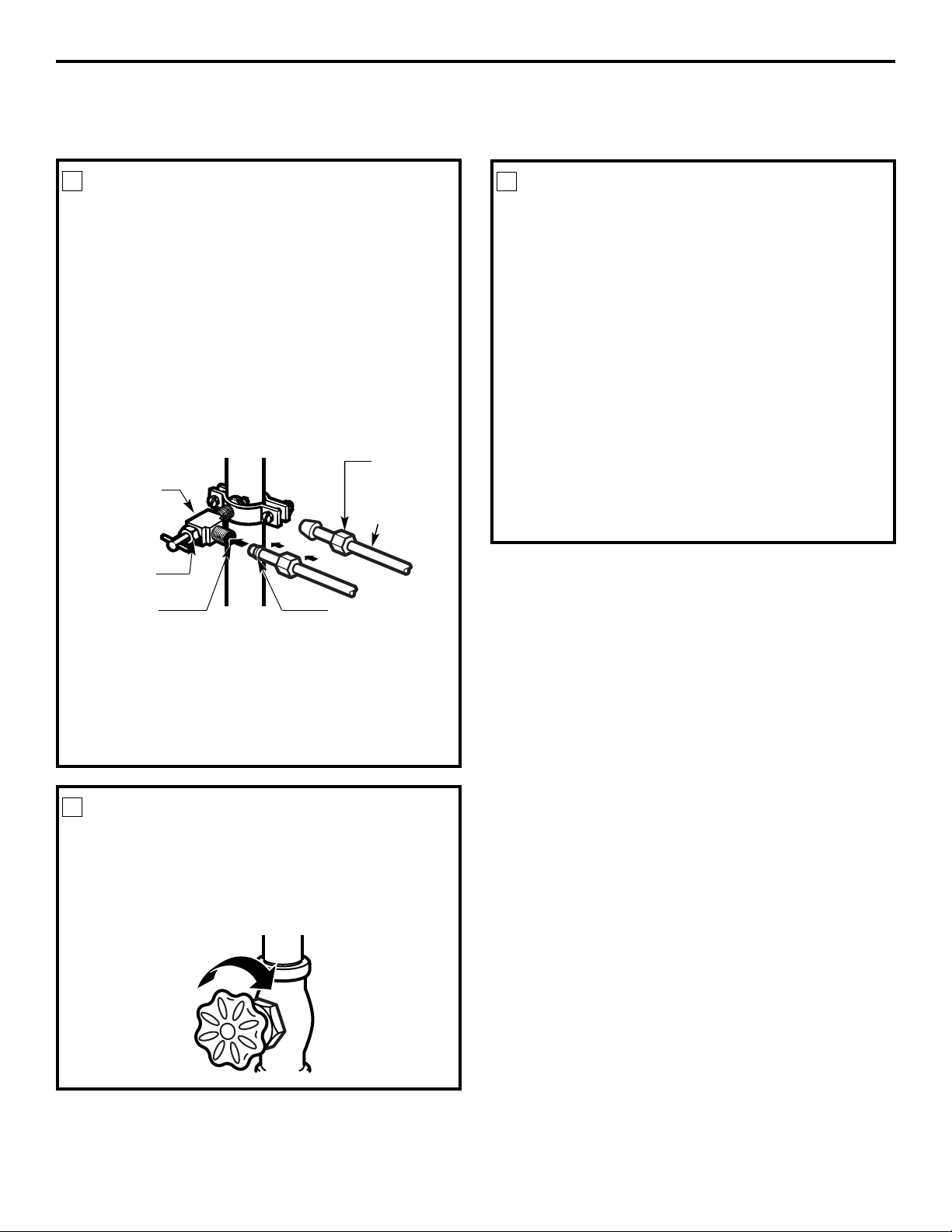
CONNECT THE TUBING TO THE
VALVE
7
Turn the main water supply on and flush out the
tubing until the water is clear.
Shut the water off at the water valve after about
one quart (1 liter) of water has been flushed
through the tubing.
FLUSH OUT THE TUBING
8
CONNECT THE TUBING TO THE
REFRIGERATOR
9
Installation Instructions
Check if the shutoff valve is closed before
advancing to the next step.
NOTE: Commonwealth of Massachusetts Plumbing
Codes 248CMR shall be adhered to. Saddle valves
are illegal and use is not permitted in Massachusetts.
Consult with your licensed plumber.
Saddle-Type
Shutoff Valve
Compression
Nut
SmartConnect™
Tubing
Packing Nut
Outlet Valve
Ferrule (sleeve)
Page 24
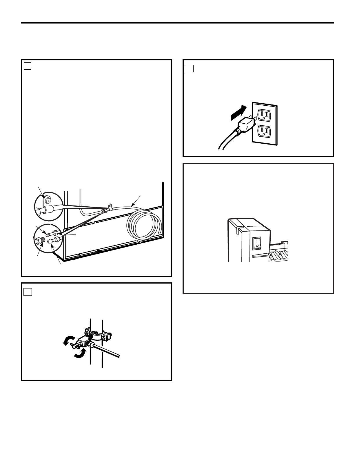
Tighten any connections that leak.
TURN THE WATER ON AT THE
SHUTOFF VALVE
10
Arrange the coil of tubing so that it does not vibrate
against the back of the refrigerator or against the
wall. Push the refrigerator back to the wall.
PLUG IN THE REFRIGERATOR
11
START THE ICEMAKER
Set the icemaker power switch to the
I (on)
position.
The icemaker will not begin to operate until it
reaches its operating temperature of 15°F (-9°C)
or below. It will then begin operation automatically
if the icemaker power switch is in the
I (on)
position.
NOTE: In lower water pressure conditions, the
water valve may turn on up to 3 times to deliver
enough water to the icemaker.
Installation Instructions
CONNECT THE TUBING TO THE
REFRIGERATOR
(CONT.)
9
Reattach the access cover.
Insert the end of the tubing into the water valve
connection as far as possible. While holding the
tubing, tighten the fitting.
For plastic tubing from a GE SmartConnect™
Refrigerator Tubing kit, insert the molded end of
the tubing into the refrigerator connection and
tighten compression nut until it is hand tight, then
tighten one additional turn with a wrench.
Overtightening may cause leaks.
Fasten the tubing into the clamp provided to hold
it in a vertical position. You may need to pry open
the clamp.
Tubing
Clamp
1/4″Compression
Nut
Ferrule
(sleeve)
SmartConnect™ Tubing
Refrigerator
Connection
1/4″Tubing
24
INSTALLING THE WATER LINE (CONT.)
Page 25
REVERSING THE DOOR SWING
When reversing the door swing:
• Read the instructions all the way through before
starting.
• Handle parts carefully to avoid scratching paint.
• Set screws down by their related parts to avoid using
them in the wrong places.
• Provide a non-scratching work surface for the doors.
IMPORTANT: Once you begin, do not move the
cabinet until door-swing reversal is completed.
These instructions are for changing the hinges from
the right side to the left side—if you ever want to
change the hinges back to the right side, follow these
same instructions and reverse all references to left
and right.
Unplug the refrigerator from its electrical outlet.
Empty all door shelves, including the dairy
compartment.
IMPORTANT NOTES
Installation Instructions
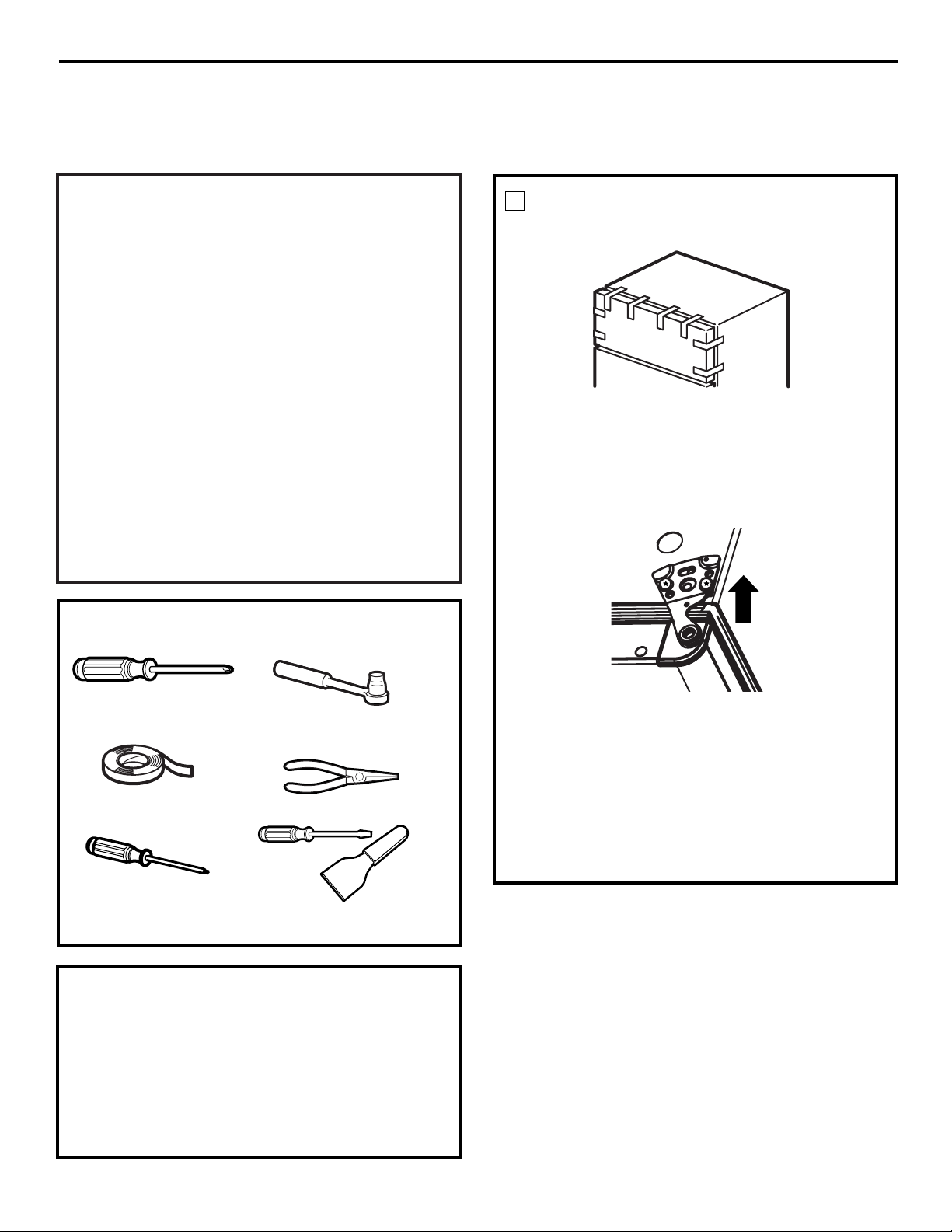
REMOVE THE FREEZER DOOR
1
7/16″ and 1/4″ socket
and ratchet
TOOLS YOU WILL NEED
Phillips screwdriver
Putty knife or
thin-blade screwdriver
Tape the door shut with masking tape.
Remove the tape and tilt the door away from the
cabinet. Lift it off the center hinge pin.
Set the door on a non-scratching surface with
the inside up.
Using a knife or putty knife with the end wrapped in
masking tape, pry out the four plug buttons from the
left top of the cabinet, and push them into the
corresponding holes on the right side.
With a 1/4″ socket and ratchet, remove the hinge
cover on top of the freezer door.
Remove the two Torx screws that hold the top hinge
to the cabinet. Then lift the hinge straight up to free
the hinge pin from the socket in the top of the door.
Masking tape
T-20 or T-25 Torx Driver,
whichever your model
requires
25
NOTE: Doors on dispenser models and doors with trim do not reverse.
PARTS YOU WILL NEED
NOTE: The parts listed below can be found in the
reversibility kit, which is taped into the bottom shelf of
the refrigerator door.
• Right end grille cap
• Left hand cam closure
• Two left hand door stops
Needle nose pliers
Page 26
26
Installation Instructions
REMOVE THE REFRIGERATOR
DOOR
2
Tape the door shut with masking tape.
Remove the center hinge pin with a 7/16″ socket
and ratchet.
Remove the tape and tilt the door away from the
cabinet. Lift the door straight up to free its bottom
socket from the pin in the bottom hinge bracket.
Set the door on a non-scratching surface, with the
inside up.
CAUTION: Do not let door drop to the floor.
To do so could damage the door stop.
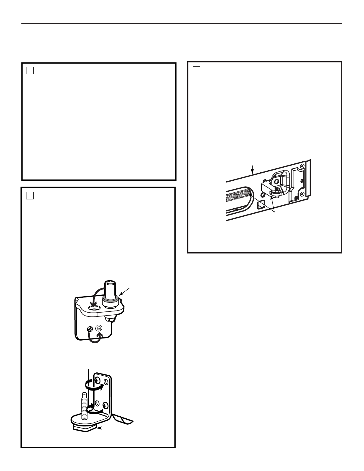
TRANSFER THE SPRING AND
WHEEL ASSEMBLY TO THE LEFT
Using needle nose pliers, tightly grip the spring and
unhook it from the bottom rail.
Pull the assembly out through the hole in the front
rail, being careful not to drop the spring.
Reinsert the assembly on the other side. This is done
by inserting the spring through the large slot in the
bottom rail, so that the end loop is visible through the
mounting hole for the mechanism. Hook this loop on
the wheel mechanism, then mount it in place.
4
REVERSING THE DOOR SWING (CONT.)
TRANSFER BOTTOM HINGE
BRACKET TO THE LEFT
Remove the base grille by pulling it straight out.
Using a Torx Driver, remove the bottom hinge
bracket.
With a 7/16″ ratchet, remove the bottom hinge pin,
along with the washer, and replace it on the other
side.
NOTE: If the washer is not on the hinge bracket, check to
see if it is stuck to the bottom of the door.
3
Using a T-20 Torx Driver, remove the stability leg from
the left side and reinstall it on the other side.
Washer
Stability Leg
Again, tightly grip the spring with the needle nose
pliers and hook it onto the bottom rail.
Spring and
Wheel Assembly
Install the bottom hinge bracket on the left side.
Bottom Rail
Page 27
Installation Instructions
27
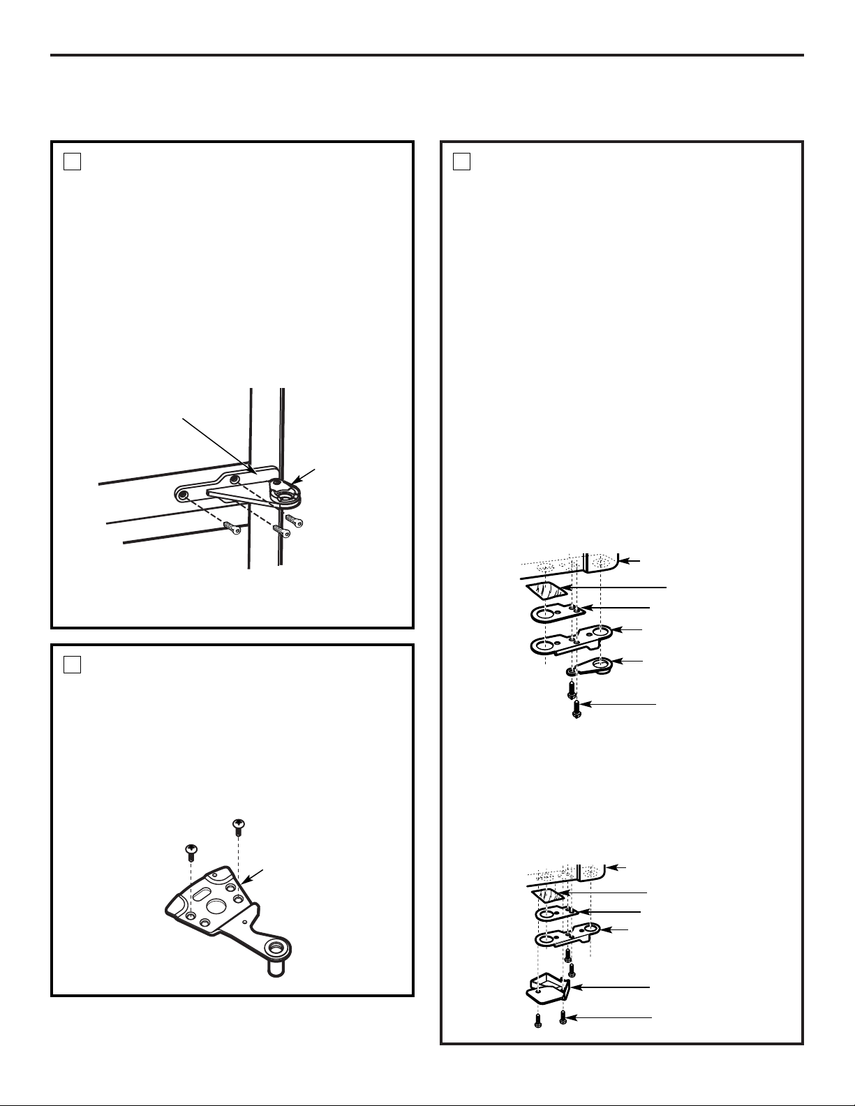
TRANSFER MIDDLE HINGE
BRACKET TO THE LEFT
With a Phillips screwdriver, remove the cam riser
from the middle hinge and place it aside.
Remove the middle hinge, along with the shim,
by removing the three Torx screws.
Remove the three Torx screws from the middle left
side of the cabinet. Screw them into the holes on the
right side. (Do not overtighten.)
Place the shim and middle hinge bracket over the
holes at the middle left side of the cabinet. Insert and
tighten the three screws.
5
TRANSFER TOP HINGE TO
THE LEFT
Position the top hinge over the screw holes in the top
left of the cabinet, ensuring that it is lined up with the
other two hinges.
Put the Torx screws two or three threads into the
holes that were not used when the hinge was on the
other side, but DO NOT tighten them at this time.
6
Reattach the cam riser to the top of the middle
hinge bracket.
Cam Riser
Middle Hinge
Bracket
Top Hinge
REMOVE DOOR STOPS, CAM
RISER AND CAM CLOSURE
Remove the left hand door stops and cam closure
from the reversibility kit. The reversibility kit is taped
onto the bottom shelf of the refrigerator door.
If you have misplaced the kit, a new one can be
ordered.
WR49M303, KIT LH White
WR49M306, KIT RH White
WR49M311, KIT LH Bisque
WR49M310, KIT RH Bisque
WR49M305, KIT LH Black
WR49M308, KIT RH Black
Contact GE Parts & Accessories 800.626.2002
or visit our Website, www.GEAppliances.com. In
Canada call 1.888.261.3055 or visit our Website,
www.geappliances.ca.
From the freezer door, remove the door stop, along
with the cam riser, spacer shims and aluminum foil
from the right side of the bottom flange, using the
T-20 Torx Driver.
7
From the refrigerator door, remove the door
stop, along with the cam closure, spacer shims and
aluminum foil from the right side of the bottom
flange using the T-20 Torx Driver.
The door stops and cam closure on the right side can
be placed in the reversibility kit bag, and the rest of
the parts can be put aside, along with the new left
hand cam closure and door stops.
Freezer Door
Tape, Aluminum
Shim, Door Stop
Door Stop
Cam Riser
Screw
Refrigerator Door
Tape, Aluminum
Shim, Door Stop
Door Stop
Closure Cam
Screw
Page 28
Installation Instructions
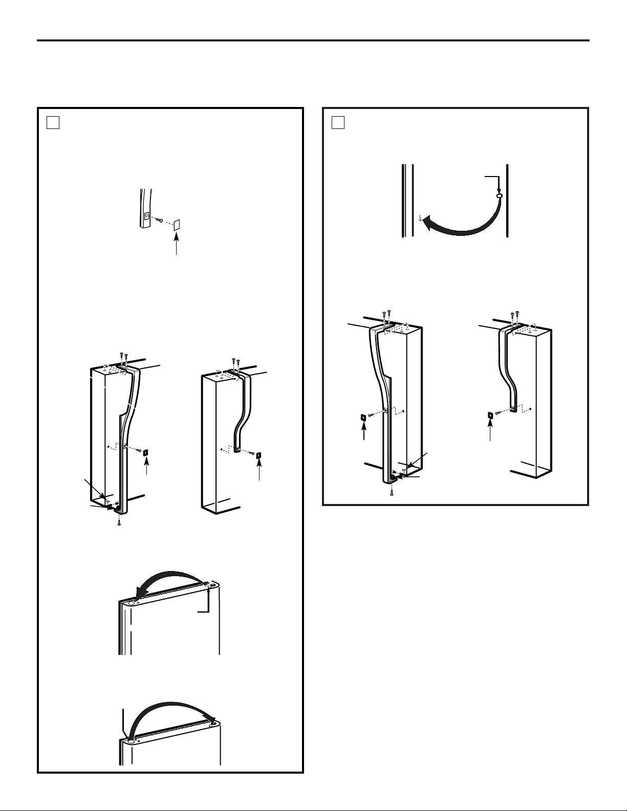
TRANSFER REFRIGERATOR
DOOR HANDLE TO THE RIGHT
To remove the handle: Remove the plug button by
carefully prying under the edge with a putty knife.
Remove the exposed screw holding the handle.
8
Remove the two screws holding the handle to the top
of the door. Pull the top of the handle away from the
door, unhook the bottom bracket from the door, and
place the assembly aside.
After removing the handle: Move the small plug
buttons from the top right side of the door top and
insert them into the holes on the opposite side.
Small Plug
Buttons
Move the large plug button from the left edge of the
door and insert it into the hole on the opposite side.
Plug Button
TRANSFER REFRIGERATOR DOOR
HANDLE TO THE RIGHT (CONT.)
Transfer the door plug button to the opposite side.
8
Button
Reinstalling the handle: Attach the handle to the
right side of the door. Reinstall the plug button.
28
Handle
Plug
Handle
Plug
Pin
Hole
Handle Plug
Short Handle
Long Handle
Long Handle
Handle
Plug
Handle
Plug
Pin
Hole
Short Handle
REVERSING THE DOOR SWING (CONT.)
Page 29
29
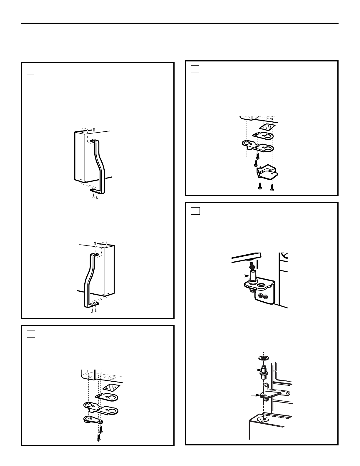
REHANG THE REFRIGERATOR
DOOR
Lower the refrigerator door onto the bottom
hinge pin.
Be sure the washer is in place.
Installation Instructions
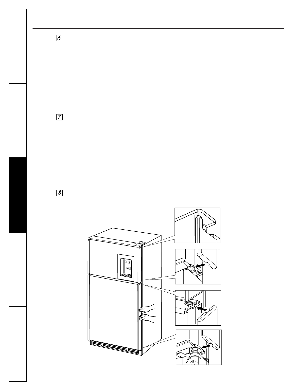
TRANSFER FREEZER DOOR
HANDLE TO THE RIGHT
CAUTION: Be careful not to scratch the door
when removing and replacing the handle.
The handle fits tightly on the door.
Remove the screws holding the handle to the top
and bottom of the door. Remove handle.
9
Move the plug button on the right side of the door
to the handle screw hole on the left side.
Reattach the handle on the opposite side using the
holes closest to the edge of the door.
11
Straighten the door and line it up with the center
hinge bracket.
Reinstall the center hinge pin with a 7/16″ socket.
Tighten it flush to the bracket.
Hinge Pin
Hinge Pin
Center Hinge
Bracket with
Cam Riser
Refrigerator Door
REINSTALL DOOR STOPS, CAM
RISER AND CAM CLOSURE
On the freezer door, install the left hand door stop,
cam riser, spacer shims and aluminum foil to the left
bottom flange.
10
REINSTALL DOOR STOPS, CAM
RISER AND CAM CLOSURE
(CONT.)
On the refrigerator door, install the left hand door
stop, cam closure, spacer shims and aluminum foil to
the left bottom flange.
10
Page 30
30
Installation Instructions
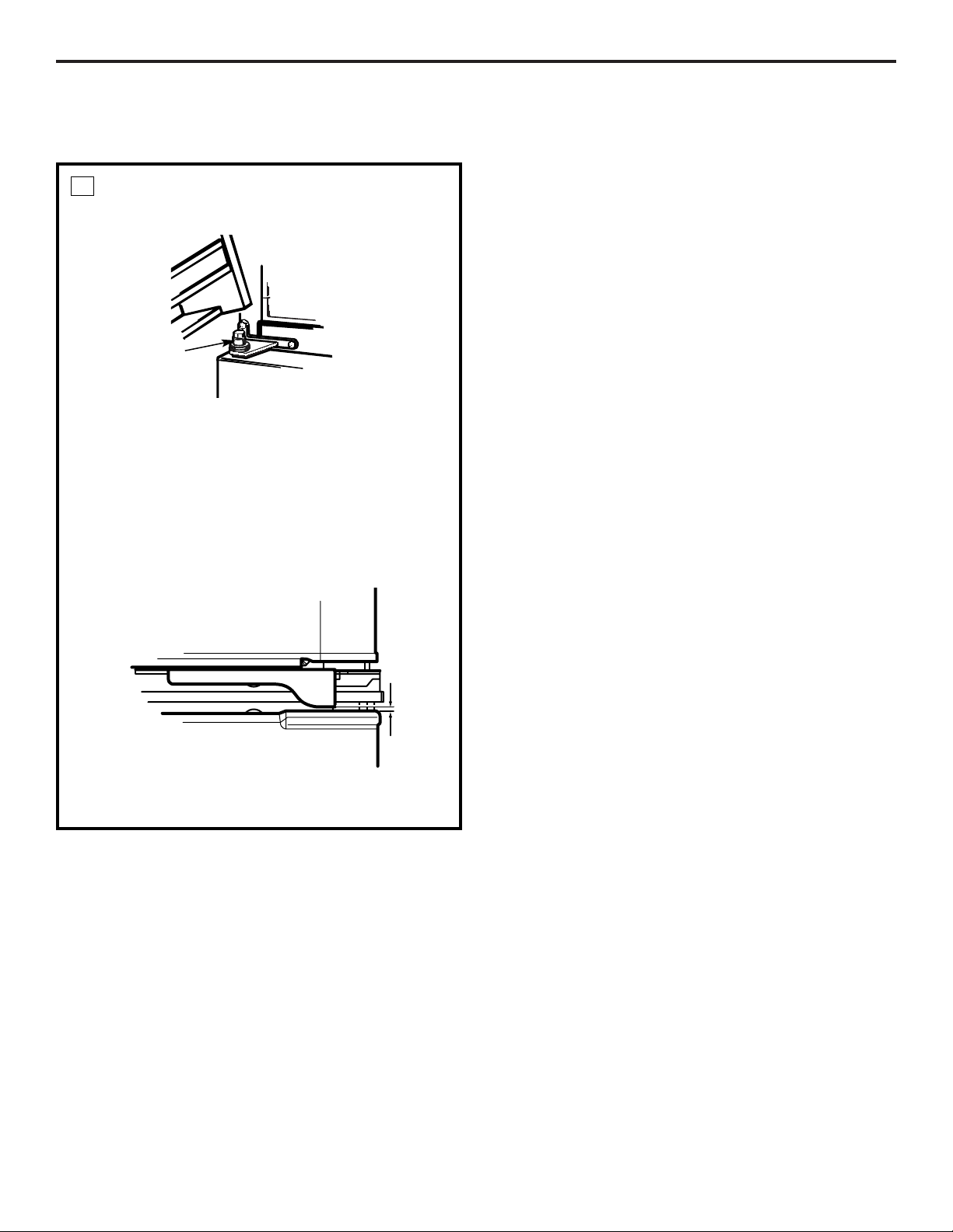
REHANG THE FREEZER DOOR
Lower the freezer door onto the center hinge pin.
12
Lift the top hinge so the pin fits into the door socket.
Support the door on the handle side and make sure
the door is straight and the gap between the doors is
even across the front. While holding the door in
place, tighten the top hinge screws.
To avoid scratching the corner cap, adjust the
bottom hinge pin so that there is a 1/16″ (1.5 mm)
gap between the door stop and the top of the door
corner cap.
Center Hinge Pin
REVERSING THE DOOR SWING (CONT.)
Reinstall the top hinge cover.
1/16″
(1.5 mm)
Gap
Page 31

Normal operating sounds.
Depending on the placement of the refrigerator in your kitchen,
you may want to place a piece of rubber-backed carpet under
the refrigerator to reduce noise.
Icemaker
(on some models). You will hear ice cubes rattle as they drop into
the ice bin. If this is your first icemaker, you’ll hear occasional sounds that
may be unfamiliar, such as the motor humming or water trickling. They are
normal icemaking sounds and are not a cause for concern.
Evaporator Fan.
You may hear air being forced through the cabinet by the fan.
Evaporator.
The flow of refrigerant through the evaporator may create a
boiling or gurgling sound.
Defrost Heater.
During defrost cycles, water dripping onto the heater may
cause a hissing or sizzling sound. After defrosting, a popping sound may
occur and the evaporator may create a boiling or gurgling sound.
Cold Control & Defrost Timer.
These parts can produce a snapping sound when
turning the refrigerator on or off. The timer also produces a sound similar to
an electric clock.
Plastic Liner.
Cracking or popping sounds may be heard due to expansion of
the plastic liner.
Water Valve
(on models equipped with an automatic icemaker). When the
icemaker fills with water you may hear a click, a buzzing sound or running
water.
Water Pan.
Water may be heard running into the drain pan during the
defrost cycle.
Compressor.
Modern, high efficiency compressors operate much faster
than older models. The compressor may have a high pitched hum or
pulsating sound.
Condenser Fan.
You may hear air being forced over the condenser by the fan.
9
8
7
6
5
4
3
2
1
Before you call for service…
Troubleshooting Tips
Save time and money! Review the charts on the following
pages first and you may not need to call for service.
Problem Possible Causes What To Do
Refrigerator does not
Refrigerator in defrost cycle. • Wait about 40 minutes for defrost cycle to end.
operate
Refrigerator control in
OFF
• Move the refrigerator control to a temperature setting.
position.
Refrigerator is unplugged. • Push the plug completely into the outlet.
The fuse is blown/circuit •Replace fuse or reset the breaker.
breaker is tripped.
Vibration or rattling
Front roller screws or •See
Leveling rollers.
(slight vibration
front leveling legs need
is normal)
adjusting.
These sounds are normal
and are due mostly to highly
efficient operation.
1
2
3
4
5
6
7
8
9
10
10
www.GEAppliances.com
Consumer SupportTroubleshooting Tips
Operating InstructionsSafety Instructions
Installation Instructions
31
Page 32

Problem Possible Causes What To Do
Normal when refrigerator •Wait 24 hours for the refrigerator to completely
is first plugged in. cool down.
Often occurs when large • This is normal.
amounts of food are
placed in refrigerator.
Door left open. • Check to see if package is holding door open or closing
mechanism is not engaged.
Hot weather or frequent • This is normal.
door openings.
Temperature controls • See
About the controls.
set at the coldest setting.
Grille and condenser •See
Care and cleaning.
need cleaning.
Fresh food or freezer
Temperature control not set • See
About the controls.
compartment too warm
cold enough.
Warm weather or frequent • Set the temperature control one step colder.
door openings. See
About the controls.
Door left open. • Check to see if package is holding door open or closing
mechanism is not engaged.
Frost or ice crystals
Door left open. • Check to see if package is holding door open or closing
on frozen food
mechanism is not engaged.
(frost within package
Too frequent or too long
is normal)
door openings.
Automatic icemaker
Icemaker power switch in • Set the power switch to the
l (on)
position.
does not work
the
0 (off)
position.
(on some models)
Water supply turned off or • See
Installing the water line.
not connected.
Freezer compartment • Wait 24 hours for the refrigerator to completely
too warm. cool down.
Piled up cubes in the storage •Level cubes by hand.
bin cause the icemaker
to shut off.
Ice cubes stuck in icemaker. •Turn off the icemaker, remove cubes and turn the
(Green power light on icemaker back on.
icemaker blinking.)
Ice cubes have
Ice storage bin needs cleaning. • Empty and wash bin. Discard old cubes.
odor/taste
Food transmitting odor/taste • Wrap foods well.
to ice cubes.
Interior of refrigerator • See
Care and cleaning.
needs cleaning.
Poor-tasting incoming water. •Install a water filter.
Slow ice cube freezing
Door left open. • Check to see if package is holding door open or closing
mechanism is not engaged.
Temperature control not set • See
About the controls.
cold enough.
Motor operates for
long periods or cycles
on and off frequently.
Consumer Support
Troubleshooting Tips
Operating Instructions
Safety InstructionsInstallation InstructionsTroubleshooting Tips Installation Instructions Safety Instructions
Operating Instructions
Before you call for service…
32
Page 33

Consumer SupportTroubleshooting Tips
Operating InstructionsSafety Instructions
Installation Instructions
Problem Possible Causes What To Do
Cube dispenser (on some
Icemaker turned off or • Turn on icemaker or water supply.
models) does not work
water supply turned off.
Ice cubes are frozen to •Remove cubes.
icemaker feeler arm.
Irregular ice clumps in • Break up with fingertip pressure and discard
storage container. remaining clumps.
•Freezer may be too warm. Adjust the freezer control
to a colder setting, one position at a time, until
clumps do not form.
Water filter clogged. •Replace filter cartridge or remove filter and install plug.
Dispensed water
Water dispenser has not been • Dispense 2 quarts (2 L) of water so that all water in
(on some models)
used for a long time. system is replenished.
has poor taste/odor
Poor-tasting incoming water. •Install a water filter.
Dirty water filter. •Replace filter.
Dispensed water
Normal when refrigerator •Wait 24 hours for the refrigerator to completely
is warm
is first installed. cool down.
Water dispenser has not been • Dispense more water. It is normal for the first half-glass
used for a period of time. of water to be warm because this water has been resting
in the tube between the chilling reservoir and the
dispenser.
Water dispenser does
Water supply line turned • See
Installing the water line.
not work
off or not connected.
Air may be trapped in the •Press the dispenser pad for at least two minutes.
water system.
Water filter clogged. •Replace filter cartridge or remove filter and install plug.
Water is not dispensed
Water in reservoir is •Call for service.
but icemaker is working
frozen.
Ice cubes stuck in icemaker. •Turn off the icemaker, remove cubes, and turn the
(Green power light on icemaker back on.
icemaker blinking.)
No water or ice cube
Supply line or shutoff •Call a plumber.
production
valve is clogged.
Water filter clogged. •Replace filter cartridge or remove filter and install plug.
Refrigerator has odor
Foods transmitting • Foods with strong odors should be tightly wrapped.
odor to refrigerator.
• Keep an open box of baking soda in the refrigerator;
replace every three months.
Interior needs cleaning. •See
Care and cleaning.
Moisture forms on
Not unusual during •Wipe surface dry.
outside of refrigerator
periods of high humidity.
Moisture collects inside
Too frequent or too
(in humid weather, air
long door openings.
carries moisture into
refrigerator when doors
are opened)
33
www.GEAppliances.com
Page 34

Before you call for service…
Problem Possible Causes What To Do
Interior light does
No power at outlet. •Replace fuse or reset the breaker.
not work
Lightbulb burned out. •See
Care and cleaning.
Water on kitchen floor or
Drain in the bottom of • See
Care and cleaning.
on bottom of freezer
the freezer clogged.
Cubes jammed in chute. •Poke ice through with a wooden spoon.
Water filter not tightened
properly.
Door not closing
Door gasket on hinge side •Apply paraffin wax on face of gasket.
properly
sticking or folding over.
Hot air from bottom
Normal air flow cooling •Your floor covering supplier should be consulted if you
of refrigerator
motor. In the refrigeration object to this discoloration.
process, it is normal that
heat be expelled in the
area under the refrigerator.
Some floor coverings will
discolor at these normal
and safe temperatures.
Orange glow in
Defrost heater is on. • This is normal.
the freezer
Small or hollow cubes
Water filter clogged. •Replace filter cartridge with new cartridge or with plug.
Water spurting from
Newly-installed filter cartridge. • Run water from the dispenser for 3 minutes (about
dispenser
11⁄2 gallons).
34
Consumer Support Troubleshooting Tips
Operating Instructions
Safety InstructionsInstallation InstructionsTroubleshooting Tips Installation Instructions Safety Instructions
Operating Instructions
Page 35

General Electric Company
Warranty Registration Department
P.O. Box 32150
Louisville, KY 40232-2150
GE Service Protection Plus
™
GE, a name recognized worldwide for quality and dependability, offers you
Service Protection Plus
™
—comprehensive protection on all your appliances—
No Matter What Brand!
Benefits Include:
• Backed by GE
• All brands covered
• Unlimited service calls
• All parts and labor costs included
• No out-of-pocket expenses
• No hidden deductibles
• One 800 number to call
You will be completely satisfied with our service protection or you may request your money back
on the remaining value of your contract. No questions asked. It’s that simple.
Protect your refrigerator, dishwasher, washer and dryer, range, TV, VCR and much more—any brand!
Plus there’s no extra charge for emergency service and low monthly financing is available. Even icemaker
coverage and food spoilage protection is offered. You can rest easy, knowing that all your valuable
household products are protected against expensive repairs.
Place your confidence in GE and call us in the U.S. toll-free at 800.626.2224
for more information.
*All brands covered, up to 20 years old, in the continental U.S.
We’ll Cover Any Appliance.
Anywhere. Anytime.*
Please place in envelope and mail to:
✁
Cut here
35
Page 36

Consumer Product Ownership Registration
Important
Mail
Today!
General Electric Company
Louisville, Kentucky
www.GEAppliances.com
First
Name
Mr. ■■ Ms. ■■ Mrs. ■■ Miss ■■
Street
Address
City
State
Date Placed
In Use
Month
Day
Year
Zip
Code
Apt. #
Last
Name
Phone
Number
_
_
Consumer Product Ownership Registration
Dear Customer:
Thank you for purchasing our product and thank you for placing your confidence in us.
We are proud to have you as a customer!
Follow these three steps to protect your new appliance investment:
Important: If you did not get a registration card with your
product, detach and return the form below to
ensure that your product is registered, or register
online at www.GEAppliances.com.
1
23
Model Number Serial Number
✁
Cut here
Complete and mail
your Consumer
Product Ownership
Registration today.
Have the peace of
mind of knowing we
can contact you in
the unlikely event of
a
safety modification.
After mailing the
registration below,
store this document
in a safe place. It
contains information
you will need should
you require service.
Our service number is
800.GE.CARES
(800.432.2737).
Read your Owner’s
Manual carefully.
It will help you
operate your new
appliance properly.
Model Number Serial Number
E-mail Address*
* Please provide your e-mail address to receive, via e-mail, discounts, special offers and other important
communications from GE Appliances (GEA).
■■ Check here if you do not want to receive communications from GEA’s carefully selected partners.
36
Page 37

37
Notes.
Consumer SupportTroubleshooting Tips
Operating Instructions
Safety Instructions Installation Instructions
www.GEAppliances.com
Page 38

38
Performance Data Sheet
GE SmartWater Filtration System
GWF Cartridge
Health Claim Performance Certified by NSF/ANSI*
(100% safety factors built in for unmetered usage)
Standard No. 42: Aesthetic Effects
Parameter USEPA Influent Effluent % Reduction
MCL Challenge Average Maximum Average Minimum
Chlorine – 1.9 ppm 0.02 ppm 0.05 ppm 98.90% 97.37%
T & O – – – – – –
Particulate** – 200,000 3,978 7,800 98.00% 96.10%
Standard No. 53: Health Effects
Parameter USEPA Influent Effluent % Reduction
MCL Challenge Average Maximum Average Minimum
Turbidity 1 NTU*** 24.3 NTU 0.07 NTU 0.1 NTU 99.71% 99.59%
Cysts 99.95% Reduction 105,750 26 55 99.97% 99.95%
Lead at PH 6.5 15 ppb 160 ppb 1 ppb 1 ppb 99.37% 99.37%
Lead at pH 8.5 15 ppb 150 ppb 1.8 ppb 4.3 ppb 98.80% 97.13%
Lindane 0.0002 ppm 0.00062 ppm 0.00005 ppm 0.00005 ppm 91.93% 91.93%
Atrazine 0.003 ppm 0.0084 ppm 0.002 ppm 0.003 ppm 76.19% 64.28%
2,4-D 0.100 ppm 0.272 ppm 0.042 ppm 0.090 ppm 84.89% 67.63%
Asbestos 99% 690 MFL/ml 0.32 MFL/ml 1.2 MFL/ml 99.95% 99.82%
* Tested using a flow rate of 0.5 gpm (1.8927 l/min); pressure of 120 psig (8.437 Kg/cm2); pH of 7.5±0.5; temp. of 68°±4.5°C (20°±2.5°C)
** Measurement in particles/ml
*** NTU = Nephelometric Units
Operating Specifications
■Capacity: certified for up to 300 gallons (1135 l); up to one year
■Pressure requirement: 40–120 psi (2.8–8.2 bar), non-shock
■Temperature: 33°–100°F (0.6°–38°C)
■Flow rate: 0.5 gpm (1.9 lpm)
General Installation/Operation/Maintenance Requirements
■Flush new cartridge at full flow for 3 minutes to purge out trapped air.
■Replace cartridge when flow becomes too slow.
Special Notices
■
Installation instructions; parts and service availability; and standard warranty are included with the product when shipped.
■This drinking water system must be maintained according to manufacturer’s instructions, including replacement of
filter cartridges.
■Do not use with water that is microbiologically unsafe or of unknown quality without adequate disinfection before or
after the system. Systems certified for cyst reduction may be used on disinfected water that may contain filterable cysts.
■
The contaminants or other substances removed or reduced by this water treatment system are not necessarily in your water.
■Check for compliance with the state and local laws and regulations.
Manufactured for: General Electric Company, Louisville, KY 40225
NSF
®
System Tested and Certified by NSF International against ANSI/NSF
Standard 42 & 53 for the reduction of:
Standard No. 42: Aesthetic Effects
Chemical Unit
Taste and Odor Reduction
Chlorine Reduction, Class I
Mechanical Filtration Unit
Particulate Reduction, Class I
Standard No. 53: Health Effects
Chemical Reduction Unit
Lead and Atrazine Reduction
Lindane and 2,4-D Reduction
Mechanical Filtration Unit
Turbidity Reduction
Cyst and Asbestos Reduction
Page 39

39
State of California
For Purchases Made In Iowa:
This form must be signed and dated by the buyer and seller prior to the consummation of
this sale. This form should be retained on file by the seller for a minimum of two years.
BUYER: SELLER:
Name Name
Address Address
City State Zip City State Zip
Signature Date Signature Date
Department of Health Services
Water Treatment Device
Certificate Number
1434
00-
Date Issued: May 30, 2000
Date Revised: February 9, 2001
GE Smart Water Filtration Systems - GWF06 GWF06
GE Smart Water Filtration Systems - GWF GWF
Hotpoint Refrigerator Systems - HWF HWF
General Electric Appliances
Cysts (protozoan)
Turbidity
Atrazine
Lindane
2,4-D
Asbestos
Lead
300 gallons* 0.5 gpm
Page 40

40
CUSTOMER WARRANTY
(for customers in Canada)
Your refrigerator is warranted to be free of defects in material and workmanship.
What is covered How Long Warranted Parts Labour
(From Date of Sale) Repair or Replace
at Camco’s Option
Compressor Five (5) Years Five (5) Years Five (5) Years
Sealed System (including Five (5) Years Five (5) Years Five (5) Years
evaporator, condenser
tubing and refrigerant)
All Other Parts One (1) Year One (1) Year One (1) Year
TERMS AND CONDITIONS:
1. This warranty applies only for single
family domestic use in Canada when the
Refrigerator has been properly installed
according to the instructions supplied by
Camco and is connected to an adequate
and proper utility service.
Damage due to abuse, accident,
commercial use, and alteration or
defacing of the serial plate cancels all
obligations of this warranty.
Service during this warranty period must
be performed by an Authorized Camco
Service Agent.
2. Neither Camco nor the Dealer is liable for
any claims or damages resulting from
failure of the Refrigerator or from service
delays beyond their reasonable control.
3.
To obtain warranty service, purchaser
must present the original Bill of Sale.
Components repaired or replaced are
warranted through the remainder of the
original warranty period only.
4. This warranty is in addition to any
statutory warranty.
WHAT IS NOT COVERED:
• Service trips to your home to teach you
how to use the product.
• Damage to finish after delivery.
• Improper installation—proper installation
includes adequate air circulation to the
refrigeration system, adequate electrical,
plumbing and other connecting facilities.
• Replacement of house fuses or resetting
of circuit breakers.
• Replacement of lightbulbs.
• Damage to product caused by accident,
fire, floods or acts of God.
• Loss of food due to spoilage.
• Proper use and care of product as listed
in the owner’s manual, proper setting of
controls.
• WARRANTOR IS NOT RESPONSIBLE
FOR CONSEQUENTIAL DAMAGES.
IMPORTANT
Keep this warranty and your bill of sale as proof of original purchase and purchase date.
Camco Service is available coast to coast.
If further help is needed concerning this
warranty, contact:
Manager, Consumer Relations
Camco Inc., Consumer Service
1 Factory Lane
Suite 310,
Moncton, New Brunswick
E1C 9M3
Staple your receipt here.
Proof of the original purchase
date is needed to obtain service
under the warranty.
Page 41

41
Refrigerator Warranty
(For customers in the United States)
All warranty service provided by our Factory Service
Centers, or an authorized Customer Care
®
technician.
To schedule service, on-line, 24 hours a day, visit us at
www.GEAppliances.com, or call 800.GE.CARES (800.432.2737).
For The Period Of: GE Will Replace:
One Year Any part
of the refrigerator which fails due to a defect in materials or workmanship.
From the date of the
During this
full one-year warranty,
GE will also provide,
free of charge,
all labor
original purchase
and in-home service to replace the defective part.
Five Years Any part of the sealed refrigerating system
(the compressor, condenser, evaporator
From the date of the
and all connecting tubing) which fails due to a defect in materials or workmanship.
original purchase
During this
full five-year sealed refrigerating system warranty,
GE will also provide,
free of charge,
all labor and in-home service to replace the defective part.
■Service trips to your home to teach you how to use the
product.
■Improper installation.
■Failure of the product if it is abused, misused, or used for
other than the intended purpose or used commercially.
■Loss of food due to spoilage.
■Replacement of house fuses or resetting of circuit
breakers.
■Damage to the product caused by accident, fire, floods or
acts of God.
■Incidental or consequential damage caused by possible
defects with this appliance.
What GE Will Not Cover:
This warranty is extended to the original purchaser and any succeeding owner for products purchased for home
use within the USA. In Alaska, the warranty excludes the cost of shipping or service calls to your home.
Some states do not allow the exclusion or limitation of incidental or consequential damages. This warranty gives
you specific legal rights, and you may also have other rights which vary from state to state. To know what your
legal rights are, consult your local or state consumer affairs office or your state’s Attorney General.
Warrantor: General Electric Company. Louisville, KY 40225
Consumer SupportTroubleshooting Tips
Operating Instructions
Safety Instructions Installation Instructions
Staple your receipt here.
Proof of the original purchase
date is needed to obtain service
under the warranty.
Page 42

42
Soutien au
consommateur
Conseils de dépannage
Fonctionnement
Mesures de sécuritéInstallation
Instructions de sécurité . . . . . . .43, 44
Instructions de fonctionnement
Clayettes, bacs et supports . . . . .47, 48
Commandes . . . . . . . . . . . . . . . . . . .45
Compartiments à fruits et
légumes et les contenants . . . . . .48, 49
Distributeur d’eau et de glaçons . . .51
Entretien et nettoyage . . . . . . . .52, 53
Filtre à eau . . . . . . . . . . . . . . . . . . . .46
Machine à glaçons automatique . . . .50
Remplacement des ampoules . . . . . .53
Instructions d’installation
Ensembles de moulures
et de panneaux décoratifs . . . . . .54–57
Installation de la
conduite d’eau . . . . . . . . . . . . . .61–65
Inversion du sens
d’ouverture des portes . . . . . . . .66–71
Préparation à l’installation
du réfrigérateur . . . . . . . . . . . . . .58–60
En cas de panne . . . . . . . . . . . .72–75
Bruits de fonctionnement
normaux . . . . . . . . . . . . . . . . . . . . .72
Soutien du consommateur
Feuillet de données relatives
à la performance . . . . . . . . . . . . . . .76
Garantie . . . . . . . . . . . . . . . . . . . . . .77
Soutien au consommateur . . . . . . . .78
Écrivez ici le numéro de modèle et le
numéro de série :
Modèle # ________________________
Série # __________________________
Vous les trouverez sur une étiquette située
dans la partie supérieure à l’intérieur du
compartiment réfrigérateur.
Page 43

Toutefois, si vous devez utiliser une rallonge électrique, il est absolument nécessaire qu’il s’agisse d’une rallonge
électrique pour électroménagers à trois fils avec mise à la terre homologuée par la CSA (au Canada) ou par
l’UL (aux États-Unis), pourvue d’une fiche et d’une prise mises à la terre, dont les valeurs nominales sont de
15 ampères (minimum) et 120 volts.
43
Soutien au
consommateur
Conseils de dépannage
Fonctionnement
Mesures de sécurité Installation
MESURES DE SÉCURITÉ IMPORTANTES.
VEUILLEZ D’ABORD LIRE LES MESURES DE SÉCURITÉ.
www.electromenagersge.
ca
MISE EN GARDE!
N’utilisez cet appareil que pour l’usage auquel il est destiné, comme expliqué dans le présent
Manuel d’utilisation.
MESURES DE SÉCURITÉ
Lorsque vous utilisez un électroménager, observez toujours les mesures de sécurité de base, notamment
les suivantes :
■
■Avant d’utiliser le réfrigérateur, assurez-vous qu’il
a été adéquatement installé conformément aux
directives d’installation.
■
■Ne laissez pas les enfants grimper ou monter sur
les clayettes du réfrigérateur, ou s’y agripper. Ils
pourraient endommager le réfrigérateur et se
blesser sérieusement.
■
■Ne touchez pas aux surfaces froides du
compartiment congélateur, surtout si vous avez
les mains moites ou mouillées. La peau risque
d’adhérer à ces surfaces extrêmement froides.
■
■Si votre réfrigérateur est doté d’une machine à
glaçons automatique, évitez tout contact avec les
pièces mobiles du mécanisme d’éjection ou avec
l’élément chauffant
situé à la partie inférieure de
la machine à glaçons. Ne mettez pas les doigts ou
les mains dans le méca-nisme de la machine à
glaçons lorsque le réfrigérateur est branché.
■
■Faites attention de ne pas vous pincer les doigts
entre les deux portes, ou entre les portes et la
carrosserie. Faites attention lorsque vous fermez
les portes et que des enfants se trouvent à
proximité de l’appareil.
■
■Débranchez le réfrigérateur avant de le nettoyer
ou de le réparer.
REMARQUE : Nous vous recommandons fortement de
confier toutes les réparations à un réparateur qualifié.
■
■Lorsque vous réglez la commande de
température à
OFF (arrêt)
, vous ne coupez
pas le courantélectrique qui alimente le circuit
de la lampe, du distributeur ou de la machine
à glaçons.
■
■Ne rangez pas ou n’utilisez pas d’essence ou
autres liquides et vapeurs inflammables à
proximité de cet appareil ou de tout autre
électroménager.
■
■Ne recongelez pas des aliments qui ont
complètement dégelé.
COMMENT VOUS DÉBARRASSER DU RÉFRIGÉRATEUR
Il arrive encore de nos jours que des enfants
s’enferment et suffoquent dans un vieux réfrigérateur.
Les réfrigérateurs abandonnés ou jetés aux rebuts
présentent encore des dangers, mêmes s’ils ne sont
laissés là «que pour quelques jours seulement». Si vous
vous débarrassez de votre ancien réfrigérateur, veuillez
suivre les directives ci-dessous pour éviter les accidents.
Avant de vous débarrasser de votre ancien
réfrigérateur ou congélateur :
■Enlevez les portes.
■Laissez les clayettes en place, de façon que les
enfants ne puissent pas facilement se glisser à
l’intérieur de l’appareil.
Élimination des CFC
Le système frigorifique de votre ancien réfrigérateur
contenait des CFC (chlorofluorocarbures). Les CFC,
croit-on, détruisent la couche d’ozone stratosphérique
qui entoure la terre.
Si vous jetez votre ancien réfrigérateur, faites enlever le
frigorigène CFC par un technicien qualifié qui en
assurera l’élimination appropriée. Si vous libérez
intentionnellement ce frigorigène CFC dans
l’atmosphère, vous vous exposez à des amendes et à
une peine d’emprisonnement en vertu des
dispositions de la législation provinciale en matière
d’environnement.
UTILISATION DE RALLONGES ÉLECTRIQUES
En raison des risques potentiels qu’elle présente dans certaines circonstances, nous déconseillons fortement
l’utilisation d’une rallonge électrique.
DANGER! RISQUE POUR LES ENFANTS
Page 44

MESURES DE SÉCURITÉ IMPORTANTES.
VEUILLEZ LIRE TOUTES LES DIRECTIVES AVANT D’UTILISER L’APPAREIL.
MISE EN GARDE!
COMMENT EFFECTUER LE RACCORDEMENT ÉLECTRIQUE
Il ne faut jamais couper ou enlever la troisième broche (mise à la terre) de la fiche du cordon
d’alimentation. Pour votre sécurité, cet appareil doit être adéquatement mis à la terre.
Le cordon d’alimentation de cet appareil est muni
d’une fiche à trois broches (mise à la terre) qui se
branche dans une prise de courant standard à trois
alvéoles (mise à la terre) afin de réduire au minimum
les risques de chocs électriques.
Faites examiner la prise de courant et le circuit par un
électricien qualifié pour vous assurer que la prise de
courant est adéquatement mise à la terre.
Si la prise de courant est du type standard à deux
alvéoles, il vous incombe de la faire remplacer par une
prise de courant à trois alvéoles, adéquatement mise à
la terre.
Votre réfrigérateur doit toujours être branché dans sa
propre prise de courant, dont la tension est identique
à celle indiquée sur la plaque signalétique.
Cette précaution garantit un rendement optimum
de votre appareil et prévient la surcharge des circuits
électriques de votre résidence, ce qui pourrait
présenter un risque d’incendie par surchauffe des fils.
Ne débranchez jamais votre réfrigérateur en tirant sur
le cordon d’alimentation. Saisissez fermement la fiche
et tirez-la bien droit de la prise de courant.
Réparez ou remplacez immédiatement tout cordon
d’alimentation effiloché ou endommagé. N’utilisez
jamais un cordon dont l’isolant est fendillé ou
présente des marques d’abrasion.
Lorsque vous éloignez le réfrigérateur du mur,
prenez garde de ne pas endommager le cordon
d’alimentation ou de faire rouler le réfrigérateur
dessus.
UTILISATION D’UN ADAPTATEUR
(adaptateurs interdits au Canada)
Nous vous recommandons fortement de ne pas utiliser un adaptateur à cause des risques potentiels
qu’il présente dans certaines circonstances.
Toutefois, si vous décidez d’utiliser tout de même un
adaptateur, vous pouvez effectuer un
raccordement
temporaire
, si les codes locaux le permettent, dans une
prise de courant à deux alvéoles adéquatement mise
à la terre en utilisant un adaptateur homologué UL,
en vente dans la plupart des quincailleries.
La fente la plus longue de l’adaptateur doit être
alignée avec la fente la plus longue de la prise murale
afin d’assurer la polarité appropriée pour le
branchement du cordon d’alimentation.
Lorsque vous débranchez le cordon d’alimentation
de l’adaptateur, saisissez toujours l’adaptateur d’une
main pendant que vous tirez sur la fiche du cordon
d’alimentation de l’autre. Sinon, la borne de mise à la
terre de l’adaptateur risque de casser avec le temps.
Si la borne de mise à la terre de la fiche casse,
N’UTILISEZ PAS
l’appareil tant qu’une mise à la terre
adéquate n’aura pas été rétablie.
Le fait de fixer la borne de mise à la terre de l’adaptateur à la plaque
de la prise de courant n’assure pas automatiquement la mise à la
terre de l’appareil. Il faut que la vis soit en métal, non isolée, et que
la prise de courant soit mise à la terre par l’entremise du câblage de
la résidence. Faites vérifiez le circuit par un électricien qualifié pour
vous assurer que la prise est adéquatement mise à la terre.
VEUILLEZ LIRE ET SUIVRE À LA LETTRE CES MESURES DE SÉCURITÉ.
CONSERVEZ CES DIRECTIVES
Soutien au
consommateur
Conseils de dépannage Fonctionnement Mesures de sécuritéInstallation
44
Page 45

45
Commandes du réfrigérateur.
www.electromenagersge.
ca
5
7
3
Freezer
5
4
6
Refrigerator
Réglage des commandes
Commande du compartiment congélateur
La commande du compartiment congélateur maintient la température dans le congélateur.
Commande du compartiment réfrigérateur
La commande du compartiment réfrigérateur maintient la température dans le réfrigérateur.
Lorsque vous tournez la commande du compartiment réfrigérateur à
OFF (arrêt)
,
le refroidissement cesse dans les deux compartiments—réfrigérateur et congélateur—
mais vous ne coupez pas le courant électrique qui alimente le réfrigérateur.
Après avoir modifié le réglage des commandes, attendez toujours 24 heures pour permettre au réfrigérateur
d’atteindre la température que vous avez réglée.
IMPORTANT!
Lorsque vous rangez des aliments dans le compartiment réfrigérateur ou congélateur, assurez-vous
qu’ils n’empêchent pas la fermature complète des portes. Lorsque la porte demeure entrouverte, la
température à l’intérieur augmente considérablement, ce qui peut avoir un effet sur la conservation
des aliments et entraîne une consommation beaucoup plus forte d’énergie.
Lorsque vous branchez l’appareil, réglez les commandes
du réfrigérateur et du congélateur à «5». Dans les
compartiments réfrigérateur et congélateur, «5» représente
le réglage normal et «9» le réglage le plus froid.
Alignez la
valeur correspondante au réglage avec le point.
Si vous désirez augmenter ou abaisser la température,
réglez d’abord la température du réfrigérateur. Lorsque la
température désirée aura été atteinte, réglez ensuite celle
du congélateur.
Congélateur
Réfrigérateur
Soutien au
consommateur
Conseils de dépannage
Fonctionnement
Mesures de sécurité Installation
Page 46

46
Soutien au
consommateur
Conseils de dépannage Fonctionnement Mesures de sécuritéInstallation
Le filtre à eau.
Cartouche du filtre à eau
La cartouche du filtre à eau se trouve
dans le coin droit arrière supérieur du
compartiment réfrigérateur, juste audessous des commandes de température.
Remplacement du filtre
Le filtre à eau doit être remplacé tous les
6 mois ou avant en fonction de la quantité
et de la qualité d’eau utilisée.
Installation de la cartouche
du filtre à eau
S’il s’agit d’une cartouche de
remplacement, enlevez d’abord
l’ancienne en la tournant lentement
vers la gauche.
Ne tirez pas
sur la
cartouche. Un peu d’eau peut s’écouler.
(Gardez le bouchon de dérivation du
filtre dans un endroit sûr).
Déballez le nouveau filtre.
(Chaque nouveau réfrigérateur est
livré avec un spécimen de filtre à eau
apposé à l’intérieur de la porte du
compartiment pour aliments frais).
Sur le filtre, marquez la date
(mois/année) du montage.
Remplissez la cartouche de
remplacement d’eau du robinet
immédiatement après l’installation
afin de permettre un meilleur débit
du distributeur.
Alignez la fleche sur la cartouche et
le support de cartouche. Placez le haut
de la nouvelle cartouche à l’intérieur
du support.
Ne l’enfoncez pas
dans le
porte-cartouche.
Tournez la cartouche lentement vers la
droite jusqu’au point où la cartouche
s’arrête.
NE SERREZ PAS TROP FORT.
Lorsque vous la tournez, elle se lèvera
en position automatiquement. La
cartouche fera approximativement une
1/4 rotation.
Faites couler l’eau du distributeur
pendant 3 minutes (environ 6 litres)
afin de dégager le système et empêcher
le bredouillement.
REMARQUE :
Une cartouche de
remplacement qui vient d’être installée
peut faire jaillir
l’eau du distributeur.
Bouchon de dérivation du filtre
Il faut utiliser le bouchon de dérivation
du filtre lorsqu’une cartouche de
remplacement n’est pas disponible. Le
distributeur et la machine à glaçons ne
peuvent pas fonctionner sans le filtre ou
sans le bouchon de dérivation du filtre.
Filtres de remplacement :
Pour commander des cartouches
supplémentaires aux États-Unis, visitez notre
site Web à l’adresse www.GEAppliances.com,
ou appelez le Service des pièces et
accessoires GE au 800.626.2002.
GWF
Prix suggéré pour la vente au détail $34.95
Les clients au Canada doivent consulter
les pages jaunes pour savoir où se trouve
le Centre de Service Camco le plus proche
ou encore visiter notre site Web à
www.electromenagersge.ca.
Insérez le dessus de la cartouche
dans le porte-cartouche et tourne-la
lentement vers la droite.
Bouchon de
dérivation
du filtre
Portecartouche
Page 47

47
Clayettes, bacs et supports du réfrigérateur.
www.electromenagersge.
ca
Toutes les caractéristiques ne sont pas offertes sur tous les modèles.
Bac «Quick Store»
Pour ne pas endommager le réfrigérateur, assurez-vous que le bac est fermé et verrouillé avant
de refermer la porte du réfrigérateur.
Ce bac peut être installé dans la porte du compartiment réfrigérateur ou congélateur.
Tirer
2
Pousser
1
Bac «Quick Store»
Boîtier du bac
Balconnets de porte
Les balconnets de porte sont réglables et
amovibles pour que vous puissiez facilement
les apporter à votre surface de travail.
Pour enlever un balconnet :
Soulevez le
balconnet et tirez-le pour le dégager
complètement des supports moulés
dans la porte.
Pour le remettre en place ou le déplacer :
Choisissez la hauteur désirée, insérez le
balconnet dans les supports moulés de la
porte, puis faites-le glisser en place. Le
balconnet doit être accroché sur la porte.
Balconnet de porte fixe.
Pour installer le
balconnet, poussez-le, puis abaissez-le pour
le bloquer en place.
La
cloison mobile
empêche les petits articles
rangés dans le balconnet de porte de tomber,
de basculer ou de se renverser. Placez un
doigt d’un côté ou de l’autre de la cloison,
près de l’avant, puis déplacez-la vers la gauche
ou la droite, selon vos besoins.
Balconnet réglable
Balconnet fixe
Cloison
mobile
Pour enlever le bac,
soulevez-le et sortez-le de son boîtier.
Pour le déplacer,
soulevez le boîtier du bac et dégagez-le de ses supports dans la porte.
Il n’est pas nécessaire d’enlever le bac du boîtier lorsque vous le déplacez.
Soutien au
consommateur
Conseils de dépannage
Fonctionnement
Mesures de sécurité Installation
Page 48

Clayettes, bacs et supports du réfrigérateur.
48
Au sujet des compartiments à fruits et légumes et les contenants.
Toutes les caractéristiques ne sont pas offertes sur tous les modèles.
Tablettes antidébordements
Les tablettes antidébordements sont munies
de rebords spéciaux qui empêchent les
liquides renversés de couler sur les tablettes
situées au-dessous.
Compartiments à légumes et à fruits
Lorsque de l’eau s’accumule au fond des
bacs, videz-les et essuyez-les.
Compartiments à humidité contrôlée
Poussez la commande complètement vers
le réglage
Veg
(Légumes) pour obtenir le
degré d’humi-dité élevé recommandé
pour la plupart des légumes.
Poussez la commande complètement vers
le réglage
Fruit
(Fruits) pour obtenir le degré
d’humidité plus faible recommandé pour
la plupart des fruits.
Réglage des clayettes
Les clayettes des compartiments
réfrigérateur et congélateur sont
réglables.
Pour enlever
Pour remettre en place
Soulever pour dégager
2
Insérer le
crochet
supérieur
1
Abaisser
pour bloquer
en place
2
Relever
1
Tablette «Quick Space» Support à bouteille de vin amovible
Cette tablette comporte deux sections,
dont l’une se glisse sous l’autre, pour
permettre le rangement d’articles hauts
sur la clayette qui se trouve au-dessous.
Soutien au
consommateur
Conseils de dépannage
Fonctionnement
Mesures de sécuritéInstallation
Veg.
Humidity
Fruit
Page 49

49
www.electromenagersge.
ca
Pour l’enlever :
Ces bacs s’enlèvent facilement. Soulevez-les
légèrement tout en les tirant jusqu’à ce qu’ils
dépassent la
butée
.
Lorsque vous ne pouvez pas ouvrir
complètement la porte,
retirez le tiroir
le plus éloigné de celle-ci en le tirant
complètement vers l’extérieur puis faites
glisser l’autre bac vers le milieu de l’appareil,
puis enlevez-le.
Températures réglables du contenant de charcuterie
Lorsque le contenant est installé dans les
6 fentes supérieures du côté gauche et que
le levier de la commande est réglé à (Très
froid), l’air du congélateur circule autour du
contenant pour le maintenir très froid.
Vous pouvez déplacer le contenant à
n’importe quel endroit si vous ne désirez
pas obtenir cette température très froide
de conservation.
Vous pouvez régler la commande à n’importe
quel réglage entre (Froid) et (Très
Froid).
Lorsque la commande est réglée à (Froid),
la température à l’intérieur du contenant est
identique à celle du réfrigérateur.
Le réglage (Très Froid) procure une
température de conservation plus froide.
Soutien au
consommateur
Conseils de dépannage
Fonctionnement
Mesures de sécurité Installation
Enlévement du compartiment à fruits et légumes.
Enlévement du compartiment à fruits et légumes
Page 50

50
Ensemble facultatif de machine à glaçons
Si votre réfrigérateur n’est pas déjà doté
d’une machine à glaçons automatique, vous
pouvez vous procurer, moyennant des frais
supplémentaires, un ensemble de machine
à glaçons facultatif (IM-4).
Suivez les instructions données
dans le manuel d’installation inclus dans
l’ensemble facultatif de machine à glaçons.
P
Soutien au
consommateur
Conseils de dépannage
Fonctionnement
Mesures de sécuritéInstallation
Machine à glaçons automatique.
Un réfrigérateur nouvellement installé prend de 12 à 24 heures pour commencer à produire des glaçons.
Machine
à glaçons
Bras palpeur
Commutateur de marche
Lumière
verte de
fonctionnement
Machine à glaçons automatique
(sur certains modèles)
La machine à glaçons produit sept glaçons
par cycle, soit environ 100 à 130 glaçons
par 24 heures, selon la température du
compartiment congélation, la température
de la pièce, le nombre de fois que la porte est
ouverte et les autres conditions d’utilisation.
Si vous faites fonctionner le réfrigérateur
avant de raccorder l’eau à la machine à
glaçons, mettez le commutateur de marche
en position
0 (arrêt)
.
Après avoir raccordé le réfrigérateur à
l’alimentation d’eau, mettez le commutateur
de marche en position
I (marche)
. La lumière
verte de marche s’allume.
La machine à glaçons se remplira d'eau si
sa température baisse à -10°C (15°F). Un
réfrigérateur nouvellement installé prend de
12 à 24 heures pour commencer à produire
des glaçons.
Jetez les premiers lots de glaçons pour
permettre à la conduite d’eau de se purger.
Assurez-vous que rien ne gène la course du
bras palpeur.
Quand le bac se remplit jusqu’au niveau du
bras palpeur, la machine à glaçons s’arrête
de produire des glaçons.
Il est normal de trouver des glaçons qui
soient soudés ensemble.
Si vous n’utilisez pas souvent vos glaçons,
les vieux glaçons deviennent opaques,
prennent un mauvais goût et rétrécissent.
Si des glaçons se coincent dans la machine
à glaçons, la lumière verte se met à clignoter.
Pour corriger cette situation, mettez le
commutateur de marche en position
0 (arrêt)
et enlevez les glaçons. Remettez
le commutateur de marche en position
I (marche)
pour remettre en marche la
machine à glaçons.
Quand vous remettez en marche la machine
à glaçons, vous devez attendre 45 minutes
avant qu’elle se remette à fabriquer des
glaçons.
NOTE : Dans les maisons qui ont une pression d’eau
plus faible que la moyenne, vous pouvez entendre la
machine à glaçons recommencer plusieurs fois son
cycle pour produire une livraison de glaçons.
Page 51

Distributeur d’eau et de glaçons.
www.electromenagersge.
ca
Sur certains modèles
Utilisation du distributeur
Réglez le sélecteur à
CUBES
(Glaçons),
CRUSHED ICE
(Glace concassée) ou
WATER
(Eau).
Appuyez le bord du verre doucement mais
fermement contre la touche du distributeur.
Lorsqu’il n’y a aucune distribution d’eau
après l’installation du réfrigérateur, il est
possible qu’il y ait de l’air dans la
conduite d’eau. Appuyez sur la touche
du distributeur pendant au moins deux
minutes pour éliminer l’air emprisonné
dans la conduite d’eau et permettre au
système de se remplir. Pour éliminer les
impuretés dans la conduite d’eau, jetez
les six premiers verres d’eau.
Le bac de trop-plein n’est pas muni d’un
système d’écoulement. Pour éviter les taches
d’eau, nettoyez régulièrement le bac de
trop-plein et sa grille.
Un interrupteur permet d’allumer ou
d’éteindre la veilleuse du distributeur. Cette
veilleuse s’allume aussi lorsque vous appuyez
sur la touche du distributeur. Lorsqu’elle est
grillée, remplacez l’ampoule du distributeur
par une autre d’une puissance maximale
de 7 watts.
ATTENTION :
Ne placez jamais vos
doigts ou d’autres objets dans l’orifice
de sortie du distributeur de glaçons.
Bac de trop-plein
Touche du
distributeur
Compartiment de rangement du
distributeur de glace
Pour l’enlever :
Soulevez le coin gauche du bac pour le
dégager de la clayette, puis tirez sur le bac
tout en le soutenant à l’avant et à l’arrière.
Pour le remettre en place :
Faites glisser le bac jusqu’à ce que la
languette du bac soit insérée dans la fente
de la clayette. Si le bac ne va pas jusqu’au
fond, retirez-le et faites tourner le mécanisme
d’entraînement de 1/4 tour. Faites glisser
ensuite le bac jusqu’au fond.
Tourner
Mécanisme
d’entraînement
Renseignements importants concernant votre distributeur
■Ajoutez les glaçons avant de remplir le
verre de liquide afin d’éviter les
éclaboussures.
■N’ajoutez pas dans le bac à glaçons des
glaçons non fabriqués dans votre machine
à glaçons. Ils risquent d’être difficiles à
concasser ou distribuer.
■Évitez de trop remplir les verres de glaçons
et d’utiliser des verres étroits ou très hauts.
Le conduit peut se bloquer et le volet peut
geler ou se coincer. Si le conduit est bloqué
par des glaçons, dégagez-les à l’aide d’une
cuillère en bois.
■Ne mettez pas de boissons ou d’aliments
dans le bac à glaçons pour les rafraîchir
rapidement. Les boîtes, bouteilles et
paquets d’aliments placés dans le bac à
glaçons peuvent provoquer un blocage du
distributeur.
■Même si vous avez sélectionné
CUBES
(Glaçons), il est possible que de la glace
concassée tombe dans votre verre. Cela se
produit de temps à autre quand plusieurs
glaçons sont acheminés accidentellement
vers le broyeur.
■Après la distribution de glace concassée,
il est possible qu’un peu d’eau s’écoule
du conduit de distribution.
■Un amas de givre se forme parfois sur le
volet du conduit à glaçons. Ce phénomène
est normal et se produit généralement
après la distribution répétée de glace
concassée. Le givre s’évaporera après
quelque temps.
■L’eau du distributeur n’est pas glacée.
Pour obtenir une eau plus froide, ajoutez
simplement des glaçons ou de la glace
concassée dans votre verre avant
d’actionner le distributeur d’eau.
Soutien au
consommateur
Conseils de dépannage
Fonctionnement
Mesures de sécurité Installation
51
Page 52

52
Entretien et nettoyage du réfrigérateur.
Nettoyage de l’intérieur
Pour empêcher l’apparition d’odeurs
, laissez
une boîte ouverte de bicarbonate de soude
dans les compartiments réfrigérateur et
congélateur.
Débranchez le réfrigérateur avant de le nettoyer.
S’il est trop difficile de le faire, essorez bien
votre linge ou votre éponge pour enlever
l’excès d’eau lorsque vous nettoyez autour des
interrupteurs, des lampes ou des commandes.
Utilisez une solution d’eau chaude et de
bicarbonate de soude - environ 1 cuillère à
soupe (15 ml) de bicarbonate par pinte
(1 litre) d’eau - pour nettoyer tout en neutralisant les odeurs. Rincez à fond, puis essuyez.
Après avoir nettoyé les joints des portes,
appliquez une mince couche de cire de
paraffine sur les joints du côté charnières afin
de les empêcher de coller et de se déformer.
Évitez de nettoyer les tablettes de verre (sur certains
modèles) encore froides dans de l’eau très chaude, car
elles risquent de se casser à cause de l’écart excessif
de température. Manipulez les tablettes de verre avec
soin. Le verre trempé peut se briser en éclats lorsqu’il
est cogné.
Ne lavez aucune pièce en plastique du réfrigérateur
dans le lave-vaisselle.
Derrière le réfrigérateur
Faites attention lorsque vous avancez le
réfrigérateur. Tous les types de revêtement
de sol peuvent être endommagés,
particulièrement ceux qui sont coussinés
ou dont la surface est gaufrée.
Tirez le réfrigérateur en ligne droite et,
lorsque vous le remettez en place, poussez-le
vers le mur en ligne droite. Les déplacements
latéraux du réfrigérateur pourraient
endommager le revêtement de sol ou le
réfrigérateur.
Lorsque vous remettez le réfrigérateur en place,
assurez-vous de ne pas le faire rouler sur le
cordon d’alimentation ou sur la conduite
d’alimentation en eau de la machine à glaçons
(sur certains modèles).
Nettoyage de l’extérieur
Essuyez soigneusement le
bac de trop-plein du
distributeur
(sur certains modèles), sous la
grille. L’eau laissée dans le bac de trop-plein
peut former des dépôts. Enlevez ces dépôts
en versant du vinaigre non dilué dans le bac
de trop-plein. Laissez-le tremper jusqu’à ce
que les dépôts disparaissent ou qu’ils soient
suffisamment ramollis pour être éliminés
par rinçage.
Touche du distributeur
(sur certains modèles).
Nettoyez-la avec une solution d’eau tiède et
de bicarbonate de soude - environ 1 cuillère
à soupe (15 ml) de bicarbonate par pinte
(1 litre) d’eau. Rincez à fond et essuyez.
CONSEIL: Entrouvrez la porte du congélateur pour
empêcher la distribution d’eau ou de glaçons pendant
le nettoyage.
Poignées et moulures de porte
. Nettoyez-les
avec un linge imbibé d’eau savonneuse.
Séchez avec un linge sec.
Gardez l’extérieur propre
. Essuyez-le avec un
linge propre légèrement imbibé de détergent
liquide doux pour la vaisselle ou de poli pour
électroménagers. Essuyez et polissez avec un
linge doux et propre.
Les panneaux en acier inoxydable et les
poignées de porte
(sur certains modèles)
peuvent être nettoyés avec un produit
réservé à cet effet disponible
commercialement, comme par exemple
le
Stainless Steel Magic™
.
Le produit
Stainless Steel Magic™
est
disponible aux magasins Ace, True Value,
Servistar HWI et autres magasins
équivalents.
Il est possible de le commander en visitant
notre site Web, www.GEAppliances.com ou
appelez le Service des pièces et accessoires
au 800.626.2002. Demandez la pièce
portant le no WX10X15.
N'utilisez pas de la cire pour appareil ménager ou
un produit pour polir sur l’acier inoxydable.
N’essuyez pas le réfrigérateur avec un linge à
vaisselle sale ou une serviette humide. Ils
pourraient laisser un résidu qui peut endommager
la peinture. N’utilisez pas de tampons à récurer, de
produits nettoyants en poudre, de javellisants ou de
produits nettoyants contenant un javellisant, car ces
produits peuvent égratigner la peinture et la rendre
moins résistante.
Appuyer ici
pour enlever
la grille.
Soutien au
consommateur
Conseils de dépannage
Fonctionnement
Mesures de sécuritéInstallation
Page 53

53
www.electromenagersge.
ca
Vous partez en vacances?
Lorsque vous vous absentez pour une
longue période, débranchez le cordon
d’alimentation de la prise de courant et
retirez tous les aliments de l’appareil.
Nettoyez l’intérieur avec une solution d’eau
et de bicarbonate de soude, à raison d’une
cuillère à soupe (15 ml) de bicarbonate par
pinte (1 litre) d’eau. Laissez les portes
ouvertes.
Sur les modèles équipés de machine à
glaçons automatique
, placez l’interrupteur
d’alimentation de la machine sur
0 (arrêt)
et
coupez l’alimentation d’eau du réfrigérateur.
Si la température de la pièce risque de
descendre sous le point de décongélation,
demandez à un réparateur qualifié de
vidanger le système d’alimentation en eau
(sur certains modèles) afin d’éviter tout
dommage imputable à une inondation.
Vous déménagez?
Immobilisez toutes les pièces amovibles,
comme la grille, les clayettes et les bacs
de rangement, à l’aide de ruban gommé
pour éviter de les endommager.
Assurez-vous que le réfrigérateur demeure debout
pendant le déménagement.
Remplacement des ampoules
Pour remplacer une ampoule grillée,
débranchez le cordon d’alimentation de la
prise de courant. Dévissez l’ampoule après
l’avoir laissé refroidir, et remplacez-la par une
ampoule pour électroménagers de puissance
identique ou moindre.
Lorsque vous remplacez l’ampoule du
congélateur, enlevez d’abord le capot de la
lampe.
Le fait de tourner la commande de température à
OFF
(
arrêt) ne coupe pas l’alimentation électrique
au circuit des lampes.
Soutien au
consommateur
Conseils de dépannage
Fonctionnement
Mesures de sécurité Installation
Le condenseur
Vous n’avez pas besoin de nettoyer souvent
le condenseur en milieu domestique normal.
Cependant, en milieu particulièrement
gras ou poussiéreux, vous devez nettoyer
périodiquement le condenseur pour
obtenir un foncionnement efficace
de votre réfrigérateur.
Nettoyage du condenseur :
Balayez la poussière ou éliminez-la à l’aide
d’un aspirateur.
Pour obtenir de bons résultats, utilisez une
brosse spécialiement conçue à cette fin.
Vous la trouverez en vente dans la plupart
des magasins de pièces d’appareils
électroménagers.
Page 54

54
Soutien au
consommateur
Conseils de dépannage
Fonctionnement
Mesures de sécuritéInstallation
Ensembles de moulures et de panneaux décoratifs.
Pour les modèles CustomStyle
Veuillez lire attentivement toutes les directives qui suivent.
Avant de commencer
Certains modèles sont dotés de moulures permettant l’installation de panneaux décoratifs. Vous pouvez
commander des panneaux décoratifs pré-coupés acrylique blancs ou noirs ou les panneaux en acier
inoxydable au service des Pièces et accessoires de GE au 800.626.2002 ou visitez notre site Web à
www.GEAppliances.com. Au Canada, appelez le 1.888.261.3055 ou visitez notre site Web à
www.electromenagersge.ca. Ou installer des panneaux de bois s’harmonisant à vos armoires de cuisine.
Panneaux de moins de 6 mm (1/4 po) d’épaisseur
Pour installer des panneaux de bois ayant moins de 6 mm (1/4 po) d’épaisseur, vous devez couper une
entretoise, par exemple un morceau de carton de 3 mm (1/8 po) d’épaisseur, que vous insérez entre la
porte du réfrigérateur et le panneau de bois. Si vous installez des panneaux décoratifs pré-coupés, vous
trouverez dans l’ensemble des entretoises pré-coupées. L’épaisseur totale du panneau décoratif ou de bois
et de l’entretoise doit être de 6 mm (1/4 po).
Panneau surélevé ou de 19 mm (3/4 po)
Vous pouvez utiliser un panneau surélevé vissé ou collé à un panneau de base de 6 mm (1/4 po)
d’épaisseur, ou un panneau fraisé de 19 mm (3/4 po). La partie surélevée du panneau doit être conçue
de manière à permettre un dégagement d’au moins 6,7 cm (25⁄8 po) pour les doigts du côté de la poignée.
Limites de poids pour les panneaux personnalisés :
Réfrigérateur : 17 kg (38 lb) max.
Congélateur : 10 kg (22 lb) max.
Dégagement de
6,7 cm (25⁄8 po) du
côté de la poignée
Panneau
décoratif
Porte du réfrigérateur
Panneau de base
de 6 mm (1/4 po)
d’épaisseur
19 mm
(3/4 po)
Page 55

55
Ensembles de moulures.
Dimensions des panneaux de bois personnalisés
■Les parties sur le dessus des panneaux du congélateur doivent être coupées à même les panneaux.
■Les parties ombrées désignent les parties qu’il faut fraiser de 3 mm (1/8 po) derrière le panneau de
6 mm (1/4 po) (côté des poignées seulement). Dans le cas des panneaux de moins de 3 mm (1/8 po)
d’épaisseur, ces parties peuvent être coupées dans les entretoises.
Encoche
Encoche
Encoche
61,1 cm
(24
1
/16 po)
10 mm
(3/8 po)
90,8 cm (35
3
/4 po)
37,8 cm (14
7
/8 po)
39,2 cm (157/16 po)
3 mm (1/8 po)
8 mm (5/16 po)
Encoche du coin du panneau
du congélateur
10 cm (3
15
/16 po)
107,3 cm
(421/4 po)
90,8 cm (35
3
/4 po)
Encoche
Panneau du congélateur
sans distributeur
Panneau du congélateur
avec distributeur
Panneau du réfrigérateur
AVANT
Soutien au
consommateur
Conseils de dépannage
Fonctionnement
Mesures de sécurité Installation
4,4 cm (13/4 po)
Partie arrière du panneau
6,5 cm (25/8 po)
Espace libre pour les doigts
Zone latérale de la
poignée arrière
devant être fraisée
pour l'insertion des
vis de montage
Partie
avant du
panneau
6 mm
(
1
/4 po)
3 mm
(
1
/8 po)
Partie supérieure côté poignée
Page 56

56
Soutien au
consommateur
Conseils de dépannage Fonctionnement Mesures de sécuritéInstallation
Inversion de l’ouverture des portes.
Enlevez la moulure supérieure de la porte du congélateur
À l’aide d’un tournevis Torx T-20, enlevez les deux vis de fixation de la moulure supérieure.
Insérez le panneau de porte du congélateur
Abaissez le panneau du congélateur jusqu’à ce qu’il soit inséré dans la fente derrière le panneau de porte.
Faites glisser l’entretoise (nécessaire avec certains panneaux de porte) derrière le panneau décoratif.
Réinstallez la moulure supérieure de la porte du congélateur
À l’aide d’un tournevis Torx T-20, réinstallez les deux vis de fixation de la moulure supérieure. Serrez les
deux vis à un couple de serrage de 30 po-lb.
Poussez délicatement sur le panneau jusqu’à ce qu’il soit inséré dans la fente derrière la poignée de porte.
Faites glisser l’entretoise (nécessaire avec certains panneaux de porte) derrière le panneau décoratif.
Insérez le panneau de porte du réfrigérateur
Encoche
Encoche
Trous des vis de la
moulure supérieure
Pellicule
protectrice bleue
Pellicule
protectrice bleue
Panneau du
réfrigérateur
Panneau
du congélateur
Moulure latérale
du congélateur
Moulure latérale
du réfrigérateur
Retirez la moulure latérale
À l’aide d’un tournevis Phillips, retirez les quatre vis fixant la moulure latérale aux portes du réfrigérateur
et du congélateur (2 vis par porte).
Page 57

57
Soutien au
consommateur
Conseils de dépannage
Fonctionnement
Mesures de sécurité Installation
Installez la moulure latérale de la porte du congélateur
N’enlevez pas la pellicule protectrice sur
l’extérieur de la moulure latérale avant que
la moulure soit installée.
Insérez l’extrémité de la moulure latérale de la
porte du congélateur sous le coin de la moulure
supérieure, puis insérez l’autre extrémité de la
moulure latérale au-dessus de la moulure
inférieure, comme illustré. Montez la moulure
latérale sur la porte à l’aide des deux vis retirées à
l’étape 2. Assurez-vous que la moulure latérale est
correctement installé et que vous êtes satisfait de
l’apparence de toutes les pièces avant d’enlever la
pellicule protectrice bleue du ruban gommé.
Tout en maintenant la moulure en place avec une
main, enlevez graduellement la pellicule protectrice
bleue du ruban gommé. Enlevez environ 80 mm
(3 po) de pellicule à la fois, tout en appuyant sur la
moulure avec votre main à mesure que le ruban
adhésif est exposé.
Installez la moulure latérale de la porte du réfrigérateur
Installez la moulure latérale aux extrémités des
moulures supérieure et inférieure de la porte du
réfrigérateur de la façon illustrée. Montez la
moulure latérale sur la porte à l’aide des deux vis
retirées à l’étape 2. Assurez-vous que la moulure
latérale est correctement insérée et que vous êtes
satisfait de l’apparence de toutes les pièces avant
d’enlever les deux pellicules protectrices bleues du
ruban gommé.
Enlevez une longueur d’environ 80 mm (3 po) de
la pellicule protectrice bleue du haut, en appuyant
sur la moulure avec votre main à mesure que le
ruban adhésif est exposé vis-à-vis de la porte. Tirez
ensuite la pellicule protectrice bleue au bas de la
moulure sur environ 80 mm (3 po). Suivez le ruban
gommé avec votre main, en appuyant la moulure
contre la porte.
Continuez d’enlever la pellicule protectrice bleue,
en alternant entre la partie supérieure et la partie
inférieure de la moulure et en appuyant la moulure
latérale contre la porte.
Enlevez la pellicule protectrice sur l’extérieur de la moulure latérale
Page 58

AVANT DE COMMENCER
Veuillez lire toutes les directives attentivement.
•
IMPORTANT
–
Conservez ces
instructions pour l’inspecteur local.
•
IMPORTANT
–
Respectez toutes les
ordonnances et les codes locaux.
• Note à l’installateur –Assurez-vous de laisser ces
instructions au consommateur.
• Note au consommateur –Conservez ces
instructions pour référence future.
• Niveau de compétence – L’installation de cet appareil
nécessite des compétences mécaniques de base.
• Temps d’installation – Installation du réfrigérateur
15 minutes
• L’installateur est responsable de bien installer ce
réfrigérateur.
• Toute panne du produit due à une mauvaise
installation n’est pas couverte par la garantie.
• N’installez jamais votre réfrigérateur dans un
emplacement où la température ambiante sera
inférieure à 16°C (60°F). Il ne se mettra pas en marche
suffisamment souvent pour maintenir des températures
convenables.
• N’installez jamais votre réfrigérateur dans un
emplacement où la température ambiante sera
supérieure à 37°C (100°F). Il ne fonctionnera pas bien.
• Installez votre réfrigérateur sur un plancher
suffisamment solide pour le porter lorsqu’il est plein.
EMPLACEMENT DU RÉFRIGÉRATEUR
Si vous avez des questions, appelez le 1.800.361.3400
ou
visitez notre site Web à l’adresse :
www.electromenagersge.ca
Instructions
Réfrigérateur
d’installation
Profile
Modèle 22
Prévoyez les dégagements suivants pour faciliter
l’installation, la bonne circulation d’air et les
raccordements de plomberie et d’électricité :
• Côtés : 3 mm (1/8 po)
• Haut : 25 mm (1 po)
• Arrière : 13 mm (1/2 po)
Si un côté ou l’autre de votre réfrigérateur est contre un
mur, laissez 3 mm (1/8″) de dégagement pour permettre
une bonne ouverture de la porte.
Lorsque vous utilisez la trousse de pose de moulure :
Si le placard n’est pas de niveau avec l’enceinte ou est
en retrait, ménagez un espace supplémentaire de 13 mm
(1/2 po) sur le côté de la charnière de porte et sur le
haut du réfrigérateur. Assurez-vous que la porte s’ouvre
correctement :
DÉGAGEMENTS
Si votre réfrigérateur a une machine à glaçons, il faut le
brancher à une conduite d’eau froide. Vous pouvez
acheter une trousse d’alimentation d’eau GE (contenant
la tuyauterie, le robinet d’arrêt, les joints et les
instructions) chez votre revendeur ou en vous adressant
à notre site Web à l’adresse www.electromenagersge.ca
ou à notre service de Pièces et accessoires au numéro
de téléphone 1.888.261.3055.
ALIMENTATION D’EAU DE
LA MACHINE À GLAÇONS
(SUR CERTAINS MODÈLES)
58
Montage
préférentiel
Ménagez un espace
supplémentaire
Partie
supérieure du
placard
Partie
supérieure du
placard
Enceinte
Enceinte
De niveau
Enceinte Enceinte
38 mm (1
1
⁄2 po)
De
niveau
avec le
placard
Porte
Porte
16 mm
(5/8 po)
Page 59

Pour régler les roulettes :
Enlevez la grille inférieure en la tirant par le bas.
Tournez les deux vis de
réglage des roulettes avant
dans le sens horaire pour
relever le réfrigérateur, et
tournez-les dans le sens
antihoraire pour l’abaisser.
Pour ce faire, utilisez une
clé à douille de 3/8 po, une
clé à molette ou des pinces.
Les modèles CustomStyle™ sont également dotés de
roulettes arrière réglables afin que vous puissiez
aligner le réfrigérateur avec vos armoires de cuisine.
À l’aide d’une clé à douille de 5/16 po, tournez les vis
des roulettes arrière – dans le sens horaire pour relever
le réfrigérateur et dans le sens antihoraire pour
l’abaisser.
Les roulettes jouent deux rôles :
■ Les roulettes donnent la possibilité de mettre le
réfrigérateur de niveau. REMARQUE : Le réfrigérateur
doit être parfaitement de niveau pour que la machine
à glaçons fonctionne.
■ Les roulettes vous permettent d’avancer le réfrigérateur
pour le nettoyage.
■ Après avoir mis l’appareil de niveau, réglez le pied de
stabilisation pour qu’il entre en contact avec le plancher.
59
Instructions d’installation
ROULETTES
Le pied de
stabilisation
Vis de réglage
de la roulette avant
Vis de réglage de la
roulette arrière
DIMENSIONS ET SPÉCIFICATIONS
(pour les modèles CustomStyle™)
62,2 cm
(241/2 po)
91,8 cm
(361/8 po)
Armoire de
61 cm
(24 po)
Panneaux latéraux
de 62,2 cm (241/2 po)
Électricité
Eau
Espace de 19 mm (3/4 po) (jeu
de 8 mm [1/2 po] + moulures
murales de 6 mm [1/4 po])
Comptoir de
63,5 cm (25 po)
178,4 cm
(701/4 po)
Page 60

AVANT DE COMMENCER
60
Instructions d’installation
MISE EN GARDE!
Précautions pour accroître la stabilité
Le réfrigérateur est beaucoup plus lourd avec des
panneaux de porte personnalisés. Pour empêcher le
réfrigérateur de basculer vers l’avant, vous devez prendre
l’une des mesures qui suivent :
• Installez le réfrigérateur dans une alcôve ou un
enfoncement du mur dont le soffite a une hauteur
de 178,4 cm (70 1⁄4 po).
• Installez un bloc de bois de 5,1 cm x 10,2 cm
(2 po x 4 po) à la pleine largeur du réfrigérateur.
Fixez la pièce de bois à l’aide d’au moins trois vis à bois
pénétrant à une profondeur d’au moins 19 mm (3/4 po)
dans les montants du mur.
Pièce
de bois
Soffite
Vue de côté
Vue de côté
Page 61

Instructions d’installation
61
INSTALLATION DE LA CONDUITE D’EAU (SUR CERTAINS MODÈLES)
Nous recommandons les trousses d’alimentation d’eau
en cuivre WX8X2, WX8X3, WX8X4, selon le montant de
conduite dont vous avez besoin. Nous approuvons les
conduites d’eau en matière plastique GE SmartConnect
™
Regrigerator Tubing (WX08X10002, WX08X10006,
WX08X10015 et WX08X10025).
Si vous installez un système d’eau GE Reverse Osmosis
dans votre réfrigérateur, la seule installation approuvée
est celle de la trousse GE RVKIT. Pour les autres systèmes
d’osmose de l’eau, suivez les recommandations du
fabricant.
Cette installation de conduite d’eau n’est pas garantie
par le fabricant de réfrigérateur ou de machine à glaçons.
Suivez soigneusement ces instructions pour minimiser le
risque de dommages onéreux d’inondation.
Les coups de bélier (eau qui donne des coups dans les
tuyaux) dans la tuyauterie de la maison peuvent
occasionner des dommages aux pièces de votre
réfrigérateur, ainsi que des fuites ou des inondations.
Appelez un plombier certifié pour corriger les coups de
bélier avant d’installer la conduite d’eau de votre
réfrigérateur.
Pour prévenir toute brûlure et tout dommage à votre
réfrigérateur, ne branchez jamais la conduite d’eau à
une canalisation d’eau chaude.
Si vous utilisez votre réfrigérateur avant de brancher la
conduite d’eau, assurez-vous de laisser le commutateur
de la machine à glaçon en position
0 (arrêt)
.
N’installez jamais les tuyaux de la machine à glaçon dans
des endroits où la température risque de descendre en
dessous du point de congélation.
Si vous utilisez un outil électrique (comme une perceuse
électrique) pendant l’installation, assurez-vous que
l’isolement ou le câblage de cet outil empêche tout
danger de secousse électrique.
Vous devez procéder à toutes vos installations
conformément aux exigences de votre code local de
plomberie.
AVANT DE COMMENCER
CE DONT VOUS AUREZ BESOIN
• Tuyaux en cuivre ou rousse GE SmartConnect
™
Refrigerator Tubing, diamètre extérieur de 1/4 po pour
brancher le réfrigérateur à l’alimentation d’eau. Si vous
utilisez un tuyau en cuivre, assurez-vous que les deux
extrémités du tuyau soient coupées bien droit.
Pour trouver la longueur de tuyau dont vous aurez besoin :
mesurez la distance qui va du robinet d’eau situé derrière
le réfrigérateur jusqu’au tuyau d’alimentation d’eau.
Ajoutez 2,4 m (8 pi). Assurez-vous qu’il y ait assez de tuyau
en trop (environ 2,4 m [8 pi] enroulés trois fois en cercles
d’environ 25 cm [10 po] de diamètre) pour vous
permettre de décoller le réfrigérateur du mur après
l’installation.
Les trousses GE SmartConnect™Refrigerator Tubing sont
disponibles dans les dimensions suivantes :
0,6 m (2 pi) – WX08X10002
1,8 m (6 pi) – WX08X10006
4,6 m (15 pi) – WX08X10015
7,6 m (25 pi) – WX08X10025
Assurez-vous que votre trousse ait au moins 2,4 m (8 pi)
comme indiqué ci-dessus.
NOTE : Les seuls tuyaux en matière plastique approuvés
par GE sont ceux qui font fournis dans les trousses
GE SmartConnect™Refrigerator Tubing. N’utilisez
jamais un autre tuyau en matière plastique, car le tuyau
d’alimentation d’eau est tout le temps sous pression.
Certaines catégories de tuyaux en matière plastique
peuvent devenir cassants avec l’âge et peuvent se fendre,
en occasionnant des dommages d’inondation dans votre
maison.
Page 62

62
INSTALLATION DE LA CONDUITE D’EAU (SUITE)
Instructions d’installation
• Vous pouvez acheter une trousse d’alimentation d’eau
GE (contenant un tuyau, un robinet d’arrêt
et les joints énumérés ci-dessous) chez votre distributeur
local ou en le commandant au service
de pièces et accessoires, au 1.888.261.3055.
• Une alimentation d’eau froide. La pression de l’eau doit
être entre 20 et 120 p.s.i. (1,4 et 8,1 bar).
• Une perceuse électrique.
• Une clé de 1/2 po ou une clé anglaise.
• Un tournevis à lame plate et un tournevis Phillips.
• Deux écrous à compression d’un diamètre extérieur
de 1/4 po et deux bagues (manchons)—pour brancher
le tuyau en cuivre au robinet d’arrêt et au robinet d’eau
du réfrigérateur.
OU BIEN
• Si vous utilisez une trousse GE SmartConnect
™
Refrigerator Tubing, les garnitures nécessaires sont
déjà montées au tuyau.
CE DONT VOUS AUREZ BESOIN
(SUITE)
• Un robinet d’arrêt pour brancher le tuyau d’eau froide.
Le robinet d’arrêt doit avoir une entrée d’eau avec un
diamètre intérieur minimal de 5/32 po au point de
jonction avec LA CONDUITE D’EAU FROIDE.
Des robinets d’arrêt à étrier sont souvent inclus dans les
trousses d’alimentation d’eau. Avant d’acheter, assurezvous que le robinet à étrier se conforme à vos codes de
plomberie locaux.
•
Si votre canalisation d’eau actuelle a un raccord évasé à
une extrémité, vous aurez besoin d’un adaptateur (que
vous trouverez dans votre magasin de matériel de
plomberie) pour brancher le tuyau d’eau au réfrigérateur,
OU BIEN vous pouvez couper le raccord évasé à l’aide
d’un coupe-tube, puis utiliser un raccord à compression.
Ne coupez jamais l’extrémité finie d’un tuyau de la trousse
GE SmartConnect™Refrigerator Tubing.
CE DONT VOUS AUREZ BESOIN
(SUITE)
Page 63

Fixez le robinet d’arrêt au tuyau d’eau froide à l’aide
du collier de serrage.
NOTE : Vous devez vous conformer aux Codes
de plomberie 248CMR du Commonwealth of
Massachusetts. Les robinets d’arrêt à étrier sont
illégaux et leur utilisation n’est pas autorisée au
Massachusetts. Consultez votre plombier local.
FERMEZ L’ALIMENTATION
PRINCIPALE D’EAU
Ouvrez le robinet le plus proche suffisamment
longtemps pour purger le tuyau.
Installez le robinet d’arrêt sur la canalisation d’eau
potable la plus fréquemment utilisée.
1
Choisissez, pour le robinet, un emplacement
facilement accessible. Il vaut mieux le brancher de
côté à un tuyau vertical. Si vous devez le brancher à un
tuyau horizontal, faites le branchement en haut ou de
côté, plutôt qu’en bas du tuyau, pour éviter de recevoir
des sédiments du tuyau d’alimentation d’eau.
CHOISISSEZ L’EMPLACEMENT
DU ROBINET
2
Percez un trou de 1/4 po dans le tuyau d’eau, à l’aide
d’un foret dur. Enlevez toute barbure due au perçage
du trou dans le tuyau. Faites attention de ne pas laisser
de l’eau couler dans votre perceuse électrique. Si vous
ne percez pas un trou de 1/4 po, vous obtiendrez une
alimentation d’eau réduite et des glaçons plus petits.
PERCEZ UN TROU POUR LE
ROBINET
3
FIXEZ LE ROBINET D’ARRÊT
4
Serrez les vis du collier jusqu’à ce que la rondelle
d’étanchéité commence à enfler.
NOTE : Ne serrez pas trop. Vous risquez d’écraser le
tuyau de cuivre.
SERREZ LE COLLIER DE SERRAGE
5
Tuyau vertical
d’eau froide
Robinet d’arrêt
à étrier
Rondelle
Entrée
Collier de serrage
Vis du collier
Acheminez le tuyau du tuyau d’eau froide au
réfrigérateur.
Faites passer le tuyau par un trou percé dans le mur
ou le plancher (derrière le réfrigérateur ou au niveau
de l’armoire de cuisine adjacente), aussi près du mur
que possible.
NOTE : Assurez-vous qu’il y ait assez de tuyau en trop
(environ 2,44 m [8 pieds] enroulés trois fois en cercles
d’environ 25 cm [10 po] de diamètre) pour vous
permettre de décoller le réfrigérateur du mur après
l’installation.
ACHEMINEZ LE TUYAU
6
Collier de serrage
Instructions d’installation
63
Page 64

64
INSTALLATION DE LA CONDUITE D’EAU (SUITE)
Instructions d’installation
Placez un écrou de compression et une bague
(manchon) à l’extrémité du tuyau et branchez-les
au robinet d’arrêt.
Assurez-vous que le tuyau soit bien inséré dans le
robinet. Serrez fort l’écrou de compression.
Pour le tuyau en matière plastique d’une trousse
GE SmartConnect™Refrigerator Tubing, insérez
l’extrémité moulée du tuyau dans le robinet d’arrêt et
serrez l’écrou de compression à la main, puis serrez un
autre demi tour avec une clé. Si vous serrez trop fort,
vous pouvez occasionner des fuites.
BRANCHEZ LE TUYAU AU ROBINET
Ouvrez le robinet d’alimentation principale d’eau et
purgez le tuyau jusqu’à ce que l’eau soit claire.
Fermez l’eau au niveau du robinet d’eau après
écoulement d’environ 1 litre ( 1 quart) d’eau par le
tuyau.
PURGEZ LE TUYAU
NOTES :
• Avant de brancher le tuyau à votre réfrigérateur,
assurez-vous que le cordon d’alimentation électrique
du réfrigérateur ne soit pas branché à la prise
murale.
• Nous vous recommandons de poser un filtre à eau si
votre alimentation d’eau contient du sable ou des
particules qui peuvent boucher la grille du robinet
d’eau de votre réfrigérateur. Installez-le sur la
conduite d’eau près de votre réfrigérateur. Si vous
utilisez une trousse GE SmartConnect™Refrigerator
Tubing, vous aurez besoin d’un tuyau additionnel
(WX08X10002) pour brancher le filtre. Ne coupez
jamais un tuyau en matière plastique pour installer
votre filtre.
Placez l’écrou de compression et la bague (manchon)
à l’extrémité du tuyau comme l’indique l’illustration.
Si vous utilisez une trousse GE SmartConnect
™
Refrigerator Tubing, les écrous sont déjà assemblés
au tuyau.
BRANCHEZ LE TUYAU À VOTRE
RÉFRIGÉRATEUR
9
Vérifiez que le robinet d’arrêt est fermé avant de
passer à l’étape suivante.
NOTE : Vous devez vous conformer aux Codes
de plomberie 248CMR du Commonwealth of
Massachusetts. Les robinets d’arrêt à étrier sont
illégaux et leur utilisation n’est pas autorisée au
Massachusetts. Consultez votre plombier local.
Robinet d’arrêt
à étrier
Écrou de
compression
Tuyau
SmartConnect
™
Presse-joint
Robinet de sortie
Bague (manchon)
Page 65

FERMEZ L’EAU AU NIVEAU DU
ROBINET D’ARRÊT
Collet à tuyau
Écrou de
compression
de 1/4 po
Collet
(manchon)
Tuyau
SmartConnect
™
Branchement
au réfrigérateur
Tuyau
de 1/4 po
Resserrez tout joint qui fuit.
10
Disposez la spirale de tuyau en cuivre de manière
à ce qu’elle ne vibre pas contre l’arrière de votre
réfrigérateur ou contre le mur. Mettez votre
réfrigérateur à sa place contre le mur en le poussant.
BRANCHEZ VOTRE
RÉFRIGÉRATEUR
11
METTEZ EN MARCHE LA
MACHINE À GLAÇONS
Mettez le commutateur de la machine à glaçon en
position
I (marche)
. La machine à glaçons ne se met
en marche que lorsqu’elle atteint une température
de fonctionnement de – 9 °C (15°F) ou moins.
Elle commence immédiatement à fonctionner si le
commutateur de la machine à glaçons est en position
I (marche)
.
NOTE : Si votre pression d’eau est trop faible, le
robinet peut se remettre en marche jusqu’à trois fois
pour envoyer suffisamment d’eau à la machine à
glaçons.
BRANCHEZ LE TUYAU À VOTRE
RÉFRIGÉRATEUR
(SUITE)
9
Remettez en place le couvercle d’accès.
Insérez l’extrémité du tuyau dans le branchement
du robinet d’arrêt d’eau, le plus loin que possible.
Tout en tenant le tuyau, serrez le raccord.
Si vous utilisez un tuyau en matière plastique d’une
trousse GE SmartConnect™Refrigerator Tubing,
insérez l’extrémité moulée du tuyau dans le
branchement au réfrigérateur et serrez l’écrou de
compression à la main, puis serrez un autre tour avec
une clé. Si vous serrez trop fort, vous pouvez
occasionner des fuites.
Fixez le tuyau au collet fourni pour le tenir en position
verticale. Il est possible que vous ayez à disjoindre le
collet.
65
Instructions d’installation
Page 66

Instructions d’installation
INVERSION DU SENS D’OUVERTURE DES PORTES
66
Pinces à extrémités pointues
OUTILS REQUIS
Tournevis Phillips
Couteau à mastic ou tournevis à lame mince
Ruban-cache
Tournevis à tête de force
T-20 ou T-25, selon votre
modèle de réfrigérateur
Pour inverser le sens d’ouverture des portes :
• Lisez toutes les directives avant de commencer.
• Manipulez les pièces avec précaution pour éviter de
rayer la peinture.
• Posez les vis à côté des pièces correspondantes pour ne
pas les utiliser aux mauvais endroits.
• Posez les portes sur un plan de travail qui ne risque pas
de rayer la peinture.
IMPORTANT : Une fois commencée votre inversion du
sens d’ouverture des portes, ne déplacez jamais votre
réfrigérateur avant d’avoir terminé.
Ces directives s’appliquent à l’inversion des charnières
du côté droit au côté gauche. Si vous voulez remettre
les charnières à droite, suivez les mêmes directives en
inversant toutes les références aux côtés gauche et droit.
Débranchez votre réfrigérateur de sa prise électrique.
Videz toutes les clayettes de porte, y compris le
compartiment de produits laitiers.
NOTES IMPORTANTES
ENLEVEZ LA PORTE DU
COMPARTIMENT CONGÉLATION
1
Attachez la porte à l’aide de ruban-cache.
Enlevez le ruban-cache et écartez la porte du cabinet
en la faisant basculer vers vous. Soulevez-la pour
l’enlever de l’axe de la charnière centrale.
Posez la porte sur une surface qui ne raye pas,
l’extérieur vers le haut.
À l’aide d’un couteau ordinaire ou à mastic dont la lame
est recouverte de ruban-cache, enlevez les quatre
capuchons situés du côté gauche, sur le dessus de
l’appareil, puis insérez-les dans les trous correspondants
qui se trouvent du côté droit.
À l’aide d’un clef à cliquet et à douilles de 1/4 po,
enlevez le couvre-charnière sur le dessus de la porte
du congélateur.
Retirez les deux vis Torx qui fixent la charnière
supérieure au meuble puis levez la charnière
verticalement pour libérer l’axe de la douille
située à la partie supérieure de la porte.
NOTE : Les portes des modèles équipés du distributeur et les portes des modèles avec motifs décoratifs ne sont pas
réversibles.
PIÈCES REQUIS
REMARQUE : Vous trouverez les pièces ci-dessous dans
l’ensemble d’inversion des portes, qui est collé sous le
balconnet inférieur de la porte du réfrigérateur.
• Capuchon de grille droit
• Dispositif de fermeture à came gauche
• Deux butées de porte gauches
Clef à cliquet et à douilles de
7/16 po et 1/4 po
Page 67

ENLEVEZ LA PORTE DU
COMPARTIMENT RÉFRIGÉRATION
2
Fermez la porte et attachez-la à l’aide de ruban-cache.
Retirez l’axe de la charnière centrale avec une clef à
douille et à cliquet de 7/16 po.
Retirez la bande et inclinez la porte en l’éloignant du
meuble. Levez la porte verticalement pour libérer la
douille inférieure de l’axe du support de la charnière
inférieure.
Posez la porte sur une surface qui ne raye pas.
MISE EN GARDE : Ne laissez jamais tomber la
porte sur le sol. Cela pourrait endommager la
butée de porte.
Instructions d’installation
67
FAITES PASSER LE SUPPORT
DE CHARNIÈRE INFÉRIEURE
À GAUCHE
Enlevez la grille de base en la tirant droit vers vous.
À l’aide du tournevis à tête de force, enlevez le
support de la charnière inférieure.
Avec une clef à cliquet de 7/16 po, retirez l’axe
de la charnière inférieure ainsi que la rondelle et
replacez-les sur le côté opposé.
NOTE : Si la rondelle n’est pas sur le support de
charnière, vérifiez s’il n’est pas collé en bas de la porte.
3
À l’aide d’un outil Torx T-20, retirez la patte de stabilisation
sur le côté gauche et remontez-la au côté opposé.
Rondelle
Pied de stabilisation
TRANSFERT À GAUCHE DE
L’ASSEMBLAGE DU RESSORT ET
DE LA ROULETTE
À l’aide d’une pince à becs pointus, saisissez fermement
le ressort et décrochez-le du rail inférieur.
Tirez sur l’assemblage par l’orifice aménagé dans le rail
avant, en faisant attention de ne pas échapper le ressort.
Réinstallez l’assemblage de l’autre côté. Pour ce faire,
insérez le ressort dans la fente large du rail inférieur de
sorte que la boucle d’extrémité soit visible par l’orifice de
montage pour le mécanisme. Accrochez cette boucle au
mécanisme de la roulette, puis installez la pièce en place.
4
Saisissez fermement le ressort à l’aide d’une pince à becs
pointus, puis accrochez-le au rail inférieur.
Assemblage du
ressort et de la
roulette
Montez le support de charnière inférieure sur le côté
gauche.
Rail inférieur
Page 68

68
Instructions d’installation
INVERSION DU SENS D’OUVERTURE DES PORTES (SUITE)
TRANSFERT À GAUCHE DE LA
CHARNIÈRE INTERMÉDIAIRE
À l’aide d’un tournevis à embout plat, enlevez l’appui
de came situé sur la charnière inférieure, et mettez-le
de côté.
Enlevez la charnière intermédiaire, ainsi que la cale, en
retirant les trois vis Torx.
Enlevez les trois vis Torx situées vers le milieu du côté
gauche de l’appareil. Vissez-les dans les trous situés du
côté droit. (Ne serrez pas avec excès.)
Placez la cale et la charnière intermédiaire vis-à-vis des
trous situés vers le milieu du côté gauche de l’appareil.
Insérez les trois vis, puis serrez-les.
5
TRANSFERT À GAUCHE DE LA
CHARNIÈRE SUPÉRIEURE
Placez la charnière supérieure vis-à-vis des trous situés du
côté gauche sur le dessus de l’appareil, en vous assurant
qu’elle est bien placée vis-à-vis des deux autres
charnières.
Vissez les vis Torx de deux ou trois tours dans les trous
quin’étaient pas utilisés lorsque la charnière était
installée de l’autre côté, mais ne les serrez PAS
complètement pour le moment.
6
Remettez en place l’appui de came sur la charnière
intermédiaire.
Appui
de came
Charnière
intermédiaire
Charnière
supérieure
ENLÈVEMENT DES BUTÉES DE
PORTE, DE L’APPUI DE CAME ET DU
DISPOSITIF DE FERMETURE À CAME
Démontez les butées de la porte gauche et le système
de fermeture à came de l’ensemble servant à l’inversion.
L’ensemble d’inversion des portes est collé sous le balconnet
inférieur de la porte du compartiment réfrigérateur.
Si vous avez égaré la trousse, il est possible d’en
commander une autre.
WR49M303, Trousse LH (côté gauche) Blanche
WR49M306, Trousse RH (côté droit) Blanche
WR49M311, Trousse LH (côté gauche) Bisque
WR49M310, Trousse RH (côté droit) Bisque
WR49M305, Trousse LH (côté gauche) Noire
WR49M308, Trousse RH (côté droit) Noire
Contactez le Service des Pièces et Accessoires de GE au
1.888.261.3055 ou visitez notre site Web à
www.electromenagersge.ca.
Sur la porte du congélateur, enlevez la butée de porte,
ainsi que l’appui de came, les cales et le morceau de ruban
d’aluminium situés du côté droit sous la porte à l’aide d’un
tournevis Torx T-20.
7
Sur la porte du réfrigérateur, enlevez la butée de porte, ainsi
que le dispositif de fermeture à came, les cales et le
morceau de ruban d’aluminium situés du côté droit sous la
porte à l’aide d’un tournevis Torx T-20.
Vous pouvez remettre dans le sac de l’ensembled’inversion
des portes les butées de porte et le dispositif de fermeture à
came qui étaient installés du côté droit. Mettez les autres
pièces de côté avec le nouveaudispositif de fermeture à
came et les nouvelles butées de porte gauches.
Porte du congélateur
Ruban d’aluminium
Cale de la butée de porte
Butée de porte
Appui de came
Vis
Porte du réfrigérateur
Ruban d’aluminium
Cale de la butée de porte
Butée de porte
Dispositif de
fermeture à came
Vis
Page 69

FAITES PASSER LA POIGNÉE
DE PORTE DU COMPARTIMENT
RÉFRIGÉRATION À DROITE
(SUITE)
Faites passer le bouton de porte dans le trou du côté
opposé.
8
Bouchon
Remontage de la poignée : Fixez la poignée du côté
droit de la porte. Remontez le bouchon.
Poignée longue
Bouchon de
poignée
Bouchon
de poignée
Goupille
Trou
Poignée courte
69
Instructions d’installation
FAITES PASSER LA POIGNÉE
DE PORTE DU COMPARTIMENT
RÉFRIGÉRATION À DROITE
Pour enlever la poignée : Enlevez le bouchon en
l’écartant avec soins en insérant avec soins la lame du
couteau à mastiquer. Enlevez la vis qui se trouve sous
ce bouchon et qui tient la porte.
8
Enlevez les deux vis qui tiennent la poignée au haut
de la porte. Tirez sur la partie supérieure de la
poignée en l’éloignant de la porte, décrochez le
support inférieur de la porte puis mettez l’ensemble
de côté.
Après avoir enlevé la poignée : Faites passer les petits
bouchons du haut du côté droit de la porte dans les
trous du côté opposé.
Petits
bouchons
Faites passer le gros bouchon de l’extrémité gauche
de la porte dans le trou du côté opposé.
Bouchon
Bouchon
de
poignée
Bouchon
de
poignée
Goupille
Trou
Bouchon de poignée
Poignée courte
Poignée longue
Page 70

70
Instructions d’installation
INVERSION DU SENS D’OUVERTURE DES PORTES (SUITE)
Charnière
intermédiaire
avec l’appui
de came
Porte du réfrigérateur
ACCROCHEZ À NOUVEAU LA
PORTE DU COMPARTIMENT
RÉFRIGÉRATION
Faites descendre la porte du compartiment
réfrigération sur l’axe de la charnière inférieure.
Assurez-vous que la rondelle est en place.
11
Redressez la porte et alignez-la au support de la
charnière centrale.
Remontez l’axe de la charnière centrale avec une
clef de 7/16 po et serrez jusqu’à ce qu’il soit dans le
profil du support.
FAITES PASSER LA POIGNÉE
DE PORTE DU COMPARTIMENT
CONGÉLATION À DROITE
MISE EN GARDE : Faites attention de ne pas
égratigner la porte lorsque vous enlevez ou
remettez la poignée en place. La poignée
s’adapte fermement à la porte.
Enlevez les vis qui tiennent la poignée en haut et en
bas de la porte. Enlevez la poignée.
9
Faites passer le bouton qui se trouve du côté droit
de la porte dans le trou de vis de poignée du côté
gauche.
Fixez la poignée du côté opposé en utilisant les trous
les plus proches de l’arête de la porte.
Axe de charnière
Axe de charnière
RÉINSTALLATION DES BUTÉES
DE PORTE, DE L’APPUI DE CAME
ET DU DISPOSITIF DE
FERMETURE À CAME
Sous la porte du congélateur, installez du côté gauche la
butée de porte gauche, l’appui de came, les cales, ainsi
que le morceau de papier d’aluminium.
10
RÉINSTALLATION DES BUTÉES
DE PORTE, DE L’APPUI DE CAME
ET DU DISPOSITIF DE
FERMETURE À CAME
(SUITE)
Sous la porte du réfrigérateur, installez du côté gauche
la butée de porte gauche, le dispositif de fermeture à
came, les cales, ainsi que le morceau de papier
d’aluminium.
10
Page 71

ACCROCHEZ À NOUVEAU LA
PORTE DU COMPARTIMENT
CONGÉLATION
Faites descendre la porte du compartiment
congélation sur l’axe de la charnière centrale.
12
Soulevez la charnière supérieure de manière à ce que
l’axe entre dans le trou de la porte.
Soutenez la porte du côté de la poignée et assurezvous que la porte est bien droite et que l’écart entre
les portes est régulier sur toute sa longueur à l’avant.
En tenant la porte en place, serrez les vis de la
charnière supérieure.
Pour ne pas égratigner le dessus du coin de la porte,
ajustez l’axe de la charnière inférieure de façon à ce
qu’il y ait un jeu de 1,5 mm (1/16 po) entre la butée
de porte et le dessus du coin de la porte.
Axe de charnière
centrale
Remettez en place le couvre-charnière supérieur.
Jeu de 1,5 mm
(1/16 po)
71
Instructions d’installation
Page 72

72
Soutien au
consommateur
Conseils de dépannage
Fonctionnement
Mesures de sécuritéInstallation
Bruits de fonctionnement normaux.
Selon l’emplacement de votre réfrigérateur dans la cuisine, vous aurez peut-être
envie d’installer un tapis caoutchouté sous l’appareil afin d’atténuer le bruit.
Machine à glaçons
(sur certains modèles). Vous entendrez les glaçons qui tombent
dans le bac à glaçons. S’il s’agit de votre première machine à glaçons, vous
entendrez à l’occasion des bruits qui peuvent vous sembler inhabituels, comme le
bourdonnement du moteur ou l’écoulement de l’eau. Ce sont des bruits normaux
produits par la fabrication des glaçons et il n’y a pas lieu de vous inquiéter.
Ventilateur de l’évaporateur.
Il est possible que vous entendiez l’air poussé dans
l’appareil par le ventilateur.
Évaporateur.
Le frigorigène qui circule dans l’évaporateur peut produire un bruit
de bouillonnement ou un gargouillement.
Élément de dégivrage.
Pendant les cycles de dégivrage, l’eau qui s’égoutte sur
l’élément de dégivrage peut produire un crépitement ou un sifflement. Après le
dégivrage, un bruit de craquement peut se faire entendre et l’évaporateur peut
produire un bruit de bouillonnement ou un gargouillement.
Commande de température et minuterie de dégivrage.
Ces pièces peuvent faire
entendre un bruit sec lorsque le réfrigérateur se met en marche ou s’arrête.
La minu-terie de dégivrage produit aussi un bruit similaire à celui d’une pendule
électrique.
Cuve intérieure en plastique.
Bruits de craquement provoqués par l’expansion
de la cuve intérieure en plastique.
Électrovanne
(sur les modèles dotés d’une machine à glaçons). Lorsque la machine
à glaçons se remplit d’eau, il est possible que vous entendiez un bourdonnement
et l’eau qui circule dans les tuyaux.
Plateau de dégivrage.
Il est possible que vous entendiez de l’eau qui s’écoule dans
le plateau de dégivrage pendant le cycle de dégivrage.
Compresseur.
Les compresseurs modernes hautement efficaces fonctionnent
beaucoup plus rapidement que les anciens modèles. Le compresseur peut faire
entendre un bourdonnement ou un bruit de pulsation.
Ventilateur du condenseur.
Il est possible que vous entendiez le ventilateur propulser
de l’air sur le condenseur.
9
8
7
6
5
4
3
2
1
Avant d’appeler un réparateur...
Conseils de dépannage
Économisez du temps et de l’argent! Consultez d’abord les
tableaux des pages qui suivent. Vous pourriez ainsi vous
éviter un appel de service.
Ces bruits sont normaux et imputables,
pour la plupart, au fonctionnement
hautement efficace du réfrigérateur.
1
2
3
4
5
6
7
8
9
10
10
Problème Causes possibles Correctifs
Le réfrigérateur ne
Cycle de dégivrage en cours. •Attendez environ 40 minutes que le cycle de dégivrage
fonctionne pas
soit terminé.
Commande de température du •Placez la commande du réfrigérateur à un réglage de
réfrigérateur réglée à
OFF
. température.
Le réfrigérateur n’est pas branché. •Branchez correctement la fiche dans la prise de courant.
Un fusible est grillé/un • Remplacez le fusible ou réenclenchez le disjoncteur.
disjoncteur est déclenché.
Vibrations ou cliquetis
Il faut régler les vis des roulettes •Voir la section
Roulettes.
(il est normal de constater
avant ou les pieds de nivellement
une légère vibration)
avant.
Page 73

Soutien au
consommateur
Conseils de dépannage
Fonctionnement
Mesures de sécurité Installation
www.electromenagersge.
ca
Problème Causes possibles Correctifs
Phénomène normal lorsque vous •Prévoyez 24 heures pour que le réfrigérateur se refroidisse
venez de brancher votre réfrigérateur. complètement.
Phénomène fréquent lorsque vous •Ce phénomène est normal.
avez placé dans le réfrigérateur une
grande quantité d’aliments.
Porte laissée ouverte. •Vérifiez si un paquet empêche la porte de se fermer ou si
le mécanisme de fermeture de la porte est engagé.
Temps chaud ou ouverture fréquente •Ce phénomène est normal.
des portes.
Commande de température placée •Voir la section
Commandes du réfrigérateur.
au réglage le plus froid.
Il faut nettoyer le condenseur •Voir la section
Entretien et nettoyage.
et la grille.
La commande n’est pas réglée à une • Voir la section
Commandes du réfrigérateur.
température assez basse.
Temps chaud ou ouverture • Abaissez d’un cran le réglage de la commande de
fréquente des portes. température. Voir la section
Commandes du réfrigérateur.
Porte laissée ouverte. •Vérifiez si un paquet empêche la porte de se fermer ou si
le mécanisme de fermeture de la porte est engagé.
Porte laissée ouverte. •Vérifiez si un paquet empêche la porte de se fermer ou si
le mécanisme de fermeture de la porte est engagé.
Ouverture trop fréquente ou
prolongée des portes.
L’interrupteur de la machine à •Placez l’interrupteur sur la position
l (marche)
.
glaçons est sur la position
0 (arrêt)
.
L’alimentation en eau est fermée ou •Voir la section
Installation de la conduite d’eau.
non raccordée.
Température trop élevée dans •Attendez 24 heures pour permettre au réfrigérateur de se
le congélateur. refroidir complètement.
Amoncellement de glaçons • Égalisez les glaçons avec votre main.
provoquant l’arrêt de la machine
à glaçons.
Les cubes de glace sont bloqués •Arrêtez la machine à glaçons, retirez les cubes de glace et
dans la machine à glaçons. (Voyant remettez la machine à glaçons en marche.
vert allumé. Clignotement du voyant
de la machine à glaçons).
Il faut nettoyer le bac à glaçons. •Videz et nettoyez le bac à glaçons. Jetez les vieux glaçons.
Les aliments transmettent un •Emballez soigneusement les aliments.
goût/une odeur aux glaçons.
Il faut nettoyer l’intérieur •Voir la section
Entretien et nettoyage.
du réfrigérateur
Mauvais goût de l’eau qui alimente • Installez un filtre à eau.
le réfrigérateur.
Fabrication lente
Porte laissée ouverte. •Vérifiez si un paquet empêche la porte de se fermer ou si
des glaçons
le mécanisme de fermeture de la porte est engagé.
Commande réglée à une température • Voir la section
Commandes du réfrigérateur.
trop élevée.
Le moteur fonctionne
pendant de longues
périodes ou se met
en marche et s’arrête
fréquemment.
Température trop élevée
dans le réfrigérateur ou
le congélateur
Givre ou cristaux de glace
sur les aliments surgelés
(il est normal qu’il y ait
du givre à l’intérieur des
emballages)
La machine à glaçons
ne fonctionne pas
(sur certains modèles)
Les glaçons ont un
goût/une odeur
73
Page 74

74
Soutien au
consommateur
Conseils de dépannage
Fonctionnement
Mesures de sécuritéInstallation
Problème Causes possibles Correctifs
Machine à glaçons arrêtée ou • Mettez la machine à glaçons en marche ou ouvrez le robinet
alimentation en eau fermée. d’alimentation en eau.
Des glaçons sont collés au bras •Enlevez les glaçons.
régulateur de la machine à glaçons.
Glaçons collés ensemble dans le • Séparez les glaçons avec vos doigts et jetez ceux que vous
bac à glaçons. ne pouvez décoller.
•La température est peut-être trop élevée dans le
congélateur. Réglez la commande du congélateur à une
température plus basse, un cran à la fois, jusqu’à ce que les
glaçons cessent de coller ensemble.
Filtre à eau bouché. •Remplacez le filtre.
Le distributeur d’eau n’a pas été •Avant usage du distributeur d'eau, vidanger au moins
utilisé pendant une longue période. 2 pintes (2L) d’eau de façon à renouveller le contenu.
Mauvais goût de l’eau qui alimente •Installez un filtre à eau.
le réfrigérateur.
Filtre à eau sale. • Remplacez le filtre.
L’eau du premier verre du
Phénomène normal lorsque vous •Prévoyez 24 heures pour que le réfrigérateur se refroidisse
distributeur est tiède
venez d’installer votre réfrigérateur. complètement.
Le distributeur d’eau n’a pas été •Augmentez la quantité d’eau. Il est normal que le premier
utilisé pendant une longue période. demi-verre d’eau soit chaud car cette eau est demeurée
dans le tube reliant le réservoir de refroidissement et le
distributeur.
Le distributeur d’eau ne
L’alimentation en eau est fermée •Voir la section
Installation de la conduite d’eau.
fonctionne pas
ou non raccordée.
Il peut y avoir de l’air dans la • Appuyez sur la touche du distributeur pendant au moins
conduite d’eau. deux minutes.
Filtre à eau bouché. • Remplacez la cartouche du filtre ou retirez le filtre et
montez le bouchon.
La machine à glaçons
L’eau est gelée dans le réservoir. •Appelez un réparateur.
fonctionne, mais pas le
Les cubes de glace sont bloqués •Arrêtez la machine à glaçons, retirez les cubes de glace et
distributeur d’eau
dans la machine à glaçons. (Voyant remettez la machine à glaçons en marche.
vert allumé. Clignotement du voyant
de la machine à glaçons).
Pas de distribution d’eau,
Conduite d’eau ou robinet d’arrêt •Appelez un plombier.
ni de fabrication de glaçons
bloqués.
Filtre à eau bouché. • Remplacez la cartouche du filtre ou retirez le filtre et
montez le bouchon.
Le réfrigérateur dégage
Les aliments transmettent des •Les aliments présentant une odeur forte doivent être
une odeur
odeurs au réfrigérateur. emballés hermétiquement.
•Gardez une boîte ouverte de bicarbonate de soude dans le
réfrigérateur; remplacez-la tous les trois mois.
Il faut nettoyer l’intérieur. •Voir la section
Entretien et nettoyage.
De la condensation se
Phénomène normal lorsque •Essuyez la carrosserie.
forme sur la carrosserie
le temps est très humide.
Le distributeur de glaçons
(sur certains modèles)
ne fonctionne pas
L’eau du distributeur
(sur certains modèles)
a un goût/une odeur
Avant d’appeler un réparateur…
Page 75

Problème Causes possibles Correctifs
Ouverture trop fréquente ou trop
prolongée des portes.
Aucun courant à la prise de courant. •Remplacez le fusible ou réenclenchez le disjoncteur.
Ampoule grillée. •Voir la section
Entretien et nettoyage.
Orifice d’écoulement bloqué dans •Voir la section
Entretien et nettoyage.
le fond du congélateur.
Glaçons coincés dans le conduit. •Dégagez-les à l’aide d’une cuillère en bois.
Filtre à eau incorrectement serré.
La porte ne se ferme
Le joint de la porte du côté des • Appliquez de la cire de paraffine sur la face du joint.
pas correctement
charnières est collé ou replié.
Dégagement d’air chaud
Circulation d’air normale pour •Si vous désirez éviter cette décoloration, consultez votre
au bas du réfrigérateur
refroidir le moteur. Dans le fournisseur de revêtement de sol.
processus de réfrigération, il
est normal que de la chaleur soit
expulsée sous le réfrigérateur.
Certains revêtements de sol
peuvent se décolorer sous l’action
de ces températures normales
et sécuritaires.
Lueur orange dans
L’élément de dégivrage est allumé. •Ce phénomène est normal.
le congélateur
Cubes de glace petits
Filtre à eau bouché. •Remplacez la cartouche du filtre par une nouvelle
ou creux
cartouche ou par un bouchon.
L’eau jaillit du distributeur
Cartouche du filtre nouvellement •Faites couler l’eau du distributeur pendant 3 minutes
montée
.
(environ un gallon et demi).
75
De la condensation se
forme à l’intérieur (par
temps humide, l’air
introduit de l’humidité dans
le réfrigérateur lorsque les
portes sont ouvertes)
La lampe intérieure ne
fonctionne pas
Eau sur le plancher de la
cuisine ou dans le fond du
congélateur
Soutien au
consommateur
Conseils de dépannage
Fonctionnement
Mesures de sécurité Installation
www.electromenagersge.
ca
Page 76

76
Feuillet de données relatives à la performance
Cartouche GWF du système de
Filtration d’eau GE SmartWater
Revendication de performance de santé certifiée par NSF/ANSI*
(facteurs intégrés de sécurité à 100% pour une utilisation sans compteur)
Norme NO42 : Effets esthétiques
Paramètre USEPA Qualité Effluent % de réduction
MCL influent Moyenne Maximum Moyenne Minimum
Chlore – 1,9 ppm 0,02 ppm 0,05 ppm 98,90% 97,37%
T & O – – – – – –
Particules** – 200.000 3.978 7.800 98,00% 96,10%
Norme NO53 : Effets de santé
Paramètre USEPA Qualité Effluent % de réduction
MCL influent Moyenne Maximum Moyenne Minimum
Turbidité 1 NTU*** 24,3 NTU 0,07 NTU 0,1 NTU 99,71% 99,59%
Spores 99,95% réduction 105.750 26 55 99,97% 99,95%
Plomb au pH 6,5 15 ppb 160 ppb 1 ppb 1 ppb 99,37% 99,37%
Plomb au pH 8,5 15 ppb 150 ppb 1,8 ppb 4,3 ppb 98,80% 97,13%
Lindane 0,0002 ppm 0,00062 ppm 0,00005 ppm 0,00005 ppm 91,93% 91,93%
Atrazine 0,003 ppm 0,0084 ppm 0,002 ppm 0,003 ppm 76,19% 64,28%
2,4-D 0,100 ppm 0,272 ppm 0,042 ppm 0,090 ppm 84,89% 67,63%
Asbestos 99% 690 MFL/ml 0,32 MFL/ml 1,2 MFL/ml 99,95% 99,82%
* Testé utilisant un débit de 1,8927 l/min (0,5 gpm); une pression de 8,437 Kg/cm2(120 psig); un pH de 7,5 ± 0,5; et une temp. de 20° ± 2,5°C (68° ± 4,5°F).
** Mesures en particules/ml
*** NTU = unités de turbidité néphélométrique
Spécifications d’opération
■ Capacité : certifiée jusqu’à maximum de 1135 l (300 gallons); jusqu’à maximum d’un an
■ Exigence en matière de pression : 2,8 à 8,2 bar (40 à 120 psi), sans choc
■ Température : 0,6°–38 °C (33°–100 °F)
■ Débit : 1,9 lpm (0,5 gpm)
Exigences générales d’installation/opération/entretien
■ Rincez la nouvelle cartouche à plein débit pendant 3 minutes afin de libérer de l’air.
■ Remplacez la cartouche lorsque le débit devient trop lent.
Avis spéciaux
■ Les directives d’installation, la disponibilité de pièces et de service ainsi que la garantie standard sont expédiées
avec le produit.
■ Ce système d’eau potable doit être entretenu conformément aux directives du fabricant, y compris le remplacement
des cartouches du filtre.
■ N’utilisez pas lorsque l’eau présente un danger microbiologique ou lorsque l’eau est d’une qualité inconnue sans désinfecter
adéquatement le système avant ou après; le système peut servir pour de l’eau désinfectée qui pourrait contenir des spores filtrables.
■ Les contaminants ou autres substances retirées ou réduites par ce système de traitement de l’eau ne sont pas nécessairement dans
votre eau.
■ Vérifiez pour vous assurer de vous conformer aux lois et règlements locaux et de l’état.
Fabriquée pour : General Electric Company, Louisville, KY 40225
NSF
®
Le système a été testé et homologué par NSF International conformément à la norme
42 et 53 de ANSI/NSF pour la réduction de :
Norme NO42 : Effets esthétiques
Unité chimique
Réduction d’odeur et de goût
Réduction de chlore, catégorie I
Unité de filtration mécanique
Réduction de particules, catégorie I
Norme NO53 : Effets de santé
Unité de réduction chimique
Réduction de plomb et Atrazine
Réduction de Lindane et 2,4-D
Unité de filtration mécanique
Réduction de spores
Réduction de turbidité
Page 77

GARANTIE DU CLIENT
Votre réfrigérateur est garanti contre tout défaut de matériau et de fabrication.
Ce que cette garantie Durée de garantie Pièces Réparation Main d’oeuvre
couvre (à partir de la date ou remplacement
d’achat) au choix de Camco
Compresseur Cinq (5) ans Cinq (5) ans Cinq (5) ans
Système scellé (y compris Cinq (5) ans Cinq (5) ans Cinq (5) ans
l’évaporateur, la tuyauterie
du condenseur et le
frigorigène)
Toutes les autres pièces Un (1) an Un (1) an Un (1) an
77
TERMES ET CONDITIONS :
1. La présente garantie ne s’applique qu’à l’utilisation
domestique par une seule famille au Canada,
lorsque le réfrigérateur a été installé conformément
aux instructions fournies par Camco et est
alimenté correctement en eau et en électricité.
Les dommages dûs à une utilisation abusive, un
accident, une exploitation commerciale, ainsi que
la modification, l’enlèvement ou l’altération de la
plaque signalétique annulent la présente garantie.
L’entretien effectué dans le cadre de la présente
garantie doit l’être par un réparateur agréé Camco.
2. Camco et le marchand ne peuvent être tenus
pour responsables en cas de réclamations ou
dommages résultant de toute panne du
réfrigérateur ou d’un entretien retardé pour des
raisons qui raisonnablement échappent à leur
contrôle.
3. L’acheteur doit, pour obtenir un service dans le
cadre de la garantie, présenter la facture originale.
Les éléments réparés ou remplacés ne sont
garantis que pendant le restant de la période de
garantie initiale.
4. Cette garantie est en sus de toute garantie
statutaire.
EXCLUSIONS DE LA GARANTIE :
• Visites à domicile pour vous apprendre à
vous servir de l’appareil.
• Dommages causés à la peinture ou à
l’émail après livraison.
• Installation incorrecte – l’installation
correcte inclut la bonne circulation d’air pour
le système de réfrigération, des possibilités
de branchement aux circuits électriques,
d’alimentation en eau et autres.
• Remplacement des fusibles ou réarmement
des disjoncteurs.
• Remplacement des ampoules élelctriques.
• Dommages subis par l’appareil à la suite
d’un accident, d’un incendie, d’inondations
ou en cas de force majeure.
• Perte des aliments dûe à la déterioration.
• Utilisation correcte et entretien adéquat
de l’appareil selon le manuel d’utilisation,
réglage correct des commandes.
• LE GARANT N’EST PAS RESPONSABLE
DES DOMMAGES INDIRECTS.
IMPORTANT
Gardez cette garantie et votre facture originale comme preuve d’achat et preuve de la date d’achat.
Camco vous offre ses services dans tout le pays.
Pour de plus amples renseignements sur la
présente garantie, veuillez prendre contact avec :
Directeur, Relations avec les consommateurs
Camco Inc., Bureau 310
1 Factory Lane
Moncton, N.B.
E1C 9M3
Agraphez votre reçu ici.
Vous devez fournir la preuve de
l’achat original pour obtenir des
services en vertu de la garantie.
Page 78

78
Soutien au consommateur.
Site Web appareils électroménagers GE
www.electromenagersge.ca
Vous avez une question ou vous avez besoin d’aide pour votre appareil électroménager? Contactez-nous
par Internet au site www.electromenagersge.ca 24 heures par jour, tous les jours de l’année.
Service de réparations
1.800.361.3400
Service de réparations GE est tout près de vous.
Pour faire réparer votre électroménager GE, il suffit de nous téléphoner.
Studio de conception réaliste
Sur demande, GE peut fournir une brochure sur l’aménagement d’une cuisine pour les personnes
à mobilité réduite.
Écrivez: Directeur, Relations avec les consommateurs, Camco, Inc.
Bureau 310, 1 Factory Lane
Moncton, N.B. E1C 9M3
Prolongation de garantie
www.electromenagersge.ca
Achetez un contrat d’entretien GE avant que votre garantie n’expire et bénéficiez d’un rabais substantiel.
Ainsi le service après-vente GE sera toujours là après expiration de la garantie.
Visitez notre site Web ou appelez-nous au 1.800.461.3636.
Pièces et accessories
Ceux qui désirent réparer eux-mêmes leurs électroménagers peuvent recevoir pièces et accessoires
directement à la maison (cartes VISA, MasterCard et Discover acceptées).
Les directives stipulées dans le présent manuel peuvent être effectuées par n’importe quel utilisateur. Les autres
réparations doivent généralement être effectuées par un technicien qualifié. Soyez prudent, car une réparation
inadéquate peut affecter le fonctionnement sécuritaire de l’appareil.
Vous trouverez dans les pages jaunes de votre annuaire le numéro du Centre de service Camco le plus
proche. Autrement, appelez-nous au 1.888.261.3055.
Contactez-nous
Si vous n’êtes pas satisfait du service après-vente dont vous avez bénéficié :
Premièrement, communiquez avec les gens qui ont réparé votre appareil.
Ensuite, si vous n’êtes toujours pas satisfait envoyez tous les détails—numéro de téléphone compris—au
Directeur, Relations avec les consommateurs, Camco, Inc.
Bureau 310, 1 Factory Lane
Moncton, N.B. E1C 9M3
Enregistrement de votre électroménager
www.electromenagersge.ca
Vous pouvez maintenant enregister votre appareil électroménager directement sur notre site internet.
Cela améliorera nos communications et notre service après-vente. Vous pouvez également nous envoyer
par la poste le formulaire d’inscription joint à votre documentation.
Page 79

79
Soporte al consumidorSolucionar problemas
OperaciónSeguridad
Instalación
Información de seguridad . . . .80, 81
Instrucciones de operación
Cómo reemplazar las bombillas . . . .89
Compartimiento de frutas
y verduras . . . . . . . . . . . . . . . . . . . . .85
Controles . . . . . . . . . . . . . . . . . . . . .82
Cuidado y limpieza . . . . . . . . . . .88, 89
Dispensador de hielo . . . . . . . . . . . .87
Entrepaños, cestas
y recipientes . . . . . . . . . . . . . . . .83, 84
Filtro de agua . . . . . . . . . . . . . . . . . .83
Máquina de hielos automática . . . . .86
Instrucciones para la instalación
Cómo invertir el vaivén
de la puerta . . . . . . . . . . . . . . .101–107
Instalación de la tubería
del agua . . . . . . . . . . . . . . . . . . .97–101
Molduras y panels decorativos . . .90–93
Preparación para instalar
el refrigerador . . . . . . . . . . . . . . .94–96
Consejos para la solución
de problemas . . . . . . . . . . . . .108–111
Sonidos normales de operación . . .108
Soporte al consumidor
Soporte al consumidor . . . . . . . . . .115
Garantía del refrigerator . . . . . . . .114
Hoja de datos de
funcionamiento . . . . . . . . . . . . . . .112
Escriba aquí el modelo y el número
de serie:
Modelo # ________________________
Serie # __________________________
Usted los verá en una etiqueta en el
interior del compartimiento de alimentos
frescos en la parte superior.
Page 80

INFORMACIONES IMPORTANTES DE SEGURIDAD.
LEA PRIMERO TODAS LAS INSTRUCCIONES.
¡ADVERTENCIA!
Use este aparato sólo para los fines que se describen en este Manual del propietario.
PRECAUCIONES DE SEGURIDAD
Cuando use electrodomésticos, siga las precauciones básicas de seguridad, incluyendo las siguientes:
■Antes de usarse, este refrigerador deberá estar
instalado y ubicado de acuerdo con las
instrucciones de instalación.
■No permita que los niños se suban, se paren o se
cuelguen de las charolas del refrigerador. Podría
dañarse el refrigerador y causarles serias lesiones.
■No toque las superficies frías del congelador,
sobre todo cuando tenga las manos húmedas
o mojadas. La piel se podría adherir a las
superficies extremadamente frías.
■Si su refrigerador tiene un dispositivo automático
para hacer hielo, evite el contacto con las partes
móviles del mecanismo de expulsión, o con el
elemento calefactor localizado en la parte inferior
de la máquina de hacer hielos. No ponga los
dedos ni las manos en el mecanismo automático
para hacer hielo mientras el refrigerador esté
conectado.
■Aleje los dedos fuera de las áreas donde se
puede pinchar los dedos; los espacios entre las
puertas y entre las puertas y los gabinetes son
necesariamente estrechos. Cierre las puertas con
cuidado en la presencia de los niños.
■Desconecte el refrigerador antes de limpiarlo o
efectuar reparaciones.
NOTA: Recomendamos enfáticamente encargar cualquier servicio
a un personal calificado.
■El colocar el control en posición
OFF
(apagado)
no quita la corriente del circuito de la luz.
■No guarde ni use gasolina u otros vapores o
líquidos inflamables cerca de este o cualquier
otro aparato.
■No vuelva a congelar los alimentos congelados
una vez que se hayan descongelado.
DESHACERSE DEBIDAMENTE DE SU REFRIGERADOR
El atrapamiento y la sofocación de los niños no son
un problema del pasado. Los refrigeradores
abandonados son un peligro…aunque sea sólo por
“pocos días.” Si se deshace de su viejo refrigerador,
por favor siga las instrucciones abajo para
ayudarnos a prevenir algún accidente.
Antes de deshacerse de su viejo refrigerador
o congelador:
■Quite las puertas.
■Deje los entrepaños en su sitio para que los niños
no se suban.
Deshacerse del CFC
Su antiguo refrigerador tiene un sistema de
refrigeración que usó CFC (clorofluorocarbonos).
Se cree que los CFC son nocivos para el ozono
estratosférico.
Si se deshace del antiguo refrigerador, asegúrese
de que se deshaga del refrigerante con CFC
correctamente por un técnico calificado. Si se libera
a propósito el refrigerante con CFC puede estar
sujeto a las multas y al encarcelamiento bajo las
estipulaciones de la legislación ambiental.
USO DE CABLES DE EXTENSION
Debido a los accidentes potenciales que pudieran ocurrir bajo determinadas condiciones, se recomienda
estrictamente no usar cables de extensión.
Sin embargo, si decidiera usarlos, es absolutamente necesario que sea del tipo UL trifilar para aparatos
y cuente con una clavija con conexión a tierra y que el cable eléctrico sea de 15 amperios (mínimo) y
120 voltios.
¡PELIGRO! RIESGO DE QUE
UN NIÑO PUEDA QUEDAR ATRAPADO
80
Soporte al consumidor Solucionar problemas
Operación
SeguridadInstalación
Page 81

Soporte al consumidorSolucionar problemas
OperaciónSeguridad
Instalación
81
www.GEAppliances.com
¡ADVERTENCIA!
COMO CONECTAR LA ELECTRICIDAD
Bajo ninguna circunstancia debe cortar o quitar la tercera punta (tierra) de la clavija. Para su seguridad
personal, este aparato deberá conectarse debidamente a tierra.
El cable eléctrico de este aparato está equipado con
una clavija de tres puntas (tierra) que enchufa en
un contacto estándar de pared de tres salidas
(tierra) para reducir al mínimo la posibilidad de
daños por un choque eléctrico con este aparato.
Haga que un electricista calificado verifique el
enchufe de la pared y el circuito para asegurarse
que la salida esté conectada debidamente a tierra.
Donde se disponga sólo de un contacto de pared con
salida para dos puntas, es su responsabilidad personal
y su obligación reemplazarlo por un contacto
adecuado para tres puntas con conexión a tierra.
El refrigerador deberá conectarse siempre en su
propio contacto eléctrico individual que tenga
un voltaje que vaya de acuerdo con la tabla de
clasificación.
Esto garantiza la mejor ejecución y evita la
sobrecarga del circuito eléctrico de la casa y los
daños a causa del sobrecalentamiento de los cables.
Nunca desconecte el refrigerador jalando el cable.
Tome siempre firmemente la clavija y sáquela del
contacto sin doblarla.
Repare o reemplace inmediatamente todos los
cables eléctricos de servicio que se hayan desgastado
o dañado en alguna otra forma. No utilice cables
que muestren roturas o daños por abrasión a lo
largo de éste ni en la clavija o en alguno de sus
extremos.
Al alejar su refrigerador de la pared, cuide que no
pase sobre el cable o lo dañe.
USO DE LOS ADAPTADORES
(No se permite usar enchufes adaptadores en Canadá)
Debido a los accidentes potenciales relacionados con la seguridad bajo determinadas circunstancias,
recomendamos estrictamente no utilizar un adaptador para clavija.
Sin embargo, si se decidiera usar un adaptador
donde los códigos locales lo permitan, es necesario
hacer una
conexión temporal
a un contacto de pared
para dos puntas debidamente conectado a tierra
utilizando un adaptador UL, mismo que puede
adquirirse en comercios locales especializados.
La punta más larga del adaptador se deberá alinear
con la entrada larga del contacto con el fin de tener
la polaridad adecuada en la conexión de la clavija.
Al desconectar el cable del adaptador, deténgalo
siempre con una mano tirando a la vez el cable
eléctrico con la otra mano. De no hacerlo puede
causar que el adaptador se rompiera después de
mucho uso.
Si se rompiera la terminal a tierra del adaptador,
NO USE
el aparato hasta que se haya reestablecido
la conexión a tierra de manera adecuada.
La conexión de la terminal de tierra del adaptador a la
salida del contacto de pared no conecta el aparato a tierra,
a no ser que el tornillo de la tapa sea de metal y no esté
aislado y que el contacto de la pared esté conectado a
tierra a través del cableado de la casa. Un electricista
calificado deberá revisar el circuito para asegurarse de
que el contacto esté debidamente conectado a tierra.
FAVOR DE LEER Y SEGUIR CUIDADOSAMENTE
LAS PRECAUCIONES DE SEGURIDAD.
GUARDE ESTAS INSTRUCCIONES
Page 82

Los controles del refrigerador.
El ajuste de los controles
Control del congelador
El control para el congelador mantiene las temperaturas en todas partes del congelador.
Control del compartimiento del refrigerador
El control para el refrigerador mantiene las temperaturas en todas partes del compartamiento del
refrigerador.
La colocación del control del compartimiento del refrigerador en
OFF
(apagado) interrumpe el
enfriamiento en ambos compartimientos—del refrigerador y el del congelador—pero no apaga el
refrigerador.
Después de cambiar los controles, permita que transcurran 24 horas para que el refrigerador alcance la
temperatura deseada.
¡IMPORTANTE!
Cuando coloque los paquetes de alimentos en los compartimentos del congelador o del refrigerador,
asegúrese de que esos paquetes no le impidan cerrar completamente las puertas. Si alguna de las
puertas quedara parcialmente abierta, las temperaturas serían anormalmente altas, afectando la
preservación de los alimentos y aumentando el consumo de manera innecesaria.
Inicialmente ajuste los controles del compartimiento del
refrigerador y del congelador en la graduación 5. Para
el compartimiento de refrigerador y el congelador, la
graduación 5 es la temperatura normal y la 9 es la
temperatura más fría. Alinee el número con el punto.
Si quiere temperaturas más frías o más cálidas, ajuste
primero la temperatura del compartimiento del
refrigerador. Cuando esté satisfecho con ésta, ajuste
la temperatura del congelador.
5
7
3
Freezer
5
4
6
Refrigerator
82
Soporte al consumidor Solucionar problemas
Operación
SeguridadInstalación
Page 83

83
Soporte al consumidorSolucionar problemas
OperaciónSeguridad
Instalación
www.GEAppliances.com
Entrepaños, cestas y recipientes del refrigerador.
No todos los modelos tienen todas las características.
Cestas en la puerta
Las cestas pueden cambiarse fácilmente de
lugar y llevarse al área de preparación de
alimentos de la cocina con igual facilidad.
Para sacarlas:
incline la cesta hacia arriba y
tire de ella hacia afuera deslizándola sobre
los soportes moldeados hasta que salga
completamente de la puerta.
Para colocarla nuevamente en su sitio o
cambiarla de lugar:
seleccione la altura
deseada del estante, trabe la cesta en los
soportes moldeados de la puerta y deslice la
cesta hacia dentro. La cesta se enganchará
en su lugar.
Estante fijo de la puerta.
Para instalar el
estante, empújelo hacia dentro y después
hacia abajo para dejarlo fijo en su lugar.
El divisor
ayuda a prevenir que se caigan, se
derramen o se deslicen artículos pequeños
guardados en la cesta de la puerta. Coloque
un dedo en ambos lados del divisor cerca
del frente y mueva hacia adelante y hacia
atrás según se requiera.
Cesta ajustable
Estante fijo de la puerta
Divisor
El filtro de agua.
Instalar el cartucho del filtro
El cartucho del filtro de agua está ubicado
en la esquina superior derecha trasera del
compartimiento del refrigerador.
¿Cuando se debe reemplazar el filtro?
El filtro del agua debiera ser cambiado cada
seis (6) meses o antes, dependiendo del uso
y la calidad del agua.
Instalar el cartucho del filtro
Si está cambiando el cartucho, remueva
primero el viejo girándolo lentamente
hacia la izquierda. Nojale el cartucho
directamente hacia abajo. Un poco de
agua puede gotear. (Mantenga el
interruptor alterno en un lugar
seguro.)
Desempaque el nuevo filtro. (Cada
refrigerador nuevo viene equipado con
una muestra del filtro de agua que está
pegado en la parte interior de la puerta
de alimentos frescos.) Escriba en el
nuevo filtro la fecha (mes/año) de
instalación.
Llene el cartucho de reemplazo con
agua de la llave para permitir que
ocurra un mejor flujo a partir del
dispensador inmediatamente después
de la instalación.
Situando la flecha en el cartucho a la
altura del soporte del mismo, coloque
la parte superior del nuevo cartucho
hacia arriba dentro del soporte.
No
empuje el cartucho hacia arriba a
dentro del soporte.
Gire el cartucho lentamente hacia la
derecha hasta que el cartucho se pare.
NO APRETAR MUY FUERTE.
Mientras está
girándolo, el se alzará por sí mismo en
su posición. El cartucho rotará
aproximadamente 1/4 de vuelta.
Deje correr el agua desde el
dispensador por 3 minutos (aprox.
11⁄2 galons) para aclarar el sistema y
para prevenir salpicaduras.
NOTA:
Un cartucho de filtro de agua recién
instalado puede
causar el agua de chorrear
del dispensador.
Tapón de derivación del filtro
Se debe usar el tapón de derivación del
filtro cuando un cartucho de filtro de
reemplazamiento no se puede encontrar.
El dispensador y el dispositivo para hacer
hielo no pueden funcionar sin el filtro o
sin el tapón de derivación del filtro.
Filtros de recambio:
Para pedir cartuchos adicionales en los
Estados Unidos, visite nuestro sitio Web,
www.GEAppliances.com, o llame a GE
para partes y accesorios al 800.626.2002.
GWF
Precio sugerido de venta al público $34.95.
Ponga la parte superior del cartucho
hacia arriba dentro del soporte del
cartucho y gírelo lentamente hacia
la derecha.
Tapón de
derivación
del filtro
Soporte
del cartucho
Page 84

Recipientes “Quick Store”
Para evitar dañar el refrigerador, asegúrese que el recipiente esté cerrado y ajustado
antes de cerrar la puerta del refrigerador.
Este recipiente puede colocarse en la puerta de los alimentos frescos o en la del
congelador.
Para sacar el recipiente,
ejerza presión hacia arriba sobre la lengüeta mientras levanta
el recipiente sacándolo de su contenedor.
Para mover,
levante el contenedor del recipiente hacia arriba y fuera de los soportes
de la puerta. No tiene que sacar el recipiente del contenedor cuando coloque la
unidad en otro lugar.
Tire hacia usted
2
Tire hacia arriba
1
Recipiente “Quick Store”
Contenedor del
recipiente
Entrepaños, cestas y recipientes del refrigerador.
Entrepaños deslizantes a prueba de derramamientos
Los entrepaños a prueba de
derramamientos tienen bordes especiales
que están diseñados para ayudar a prevenir
derramamientos o goteos a los entrepaños
que se encuentran más abajo. Los
entrepaños se deslizan hacia delante y
hacia atrás para facilitar el acceso a ellos.
Arreglar los entrepaños
Los entrepaños de los compartimientos
de alimentos frescos y del congelador son
ajustables.
Para sacar
Para volver a colocar
Levante y saque
2
Empotre
el gancho
superior
1
Suelte
para atorar
en la
posición
correcta
2
Incline
1
Entrepaño ajustable Portavinos detachable
Este entrepaño se divide a la mitad y
se desliza bajo sí mismo para guardar
artículos altos en el entrepaño inferior.
84
Soporte al consumidor Solucionar problemas
Operación
SeguridadInstalación
Page 85

Acerca del compartimiento de frutas
y verduras y las bandejas.
www.GEAppliances.com
85
Soporte al consumidorSolucionar problemas
OperaciónSeguridad
Instalación
Sacar del compartimiento de frutas y verduras.
Para sacar:
Pueden extraerse fácilmente levantándolas
ligeramente y tirando de ellas hasta pasar el
punto donde se
atrancan.
Cuando la puerta no pueda ser abierta
completamente,
remueva la gaveta que se
encuentra lo más retirada de la puerta,
tirando hacia el frente y hacia afuera.
Entonces deslice la otra gaveta hacia el
medio y sáquela.
Cuando el compartimiento se coloca
en los 6 primeros espacios—empezando
por arriba—del lado izquierdo,
y la palanca se pone en la posición
(máximo frío), aire proveniente
del congelador es forzado a moverse
alrededor del compartimiento para
mantenerla muy fría.
Puede poner el compartimiento en
cualquier otro lugar si no quiere este
almacenaje muy frío.
El ajuste se puede colocar a cualquier
punto entre (frío) y (máximo frío).
Cuando la palanca está en la posición
(frío), el compartimiento se quedará a la
temperatura normal del refrigerador.
El ajuste de (máximo frío) proporciona
la área de almacenamiento la más fría.
Temperatura ajustable en el compartimiento del Deli
No todos los modelos tienen todas las características.
Compartimientos para frutas y vegetales
El exceso de agua que pueda acumularse
en el fondo de las gavetas deben ser vaciado
y las gavetas deben ser secadas.
Compartimientos con humedad ajustable
Deslice el control hasta llegar a la posición
Veg.
(vegetales) para proporcionar el alto
nivel de humedad recomendado para la
mayoría de los vegetales.
Deslice el control hasta llegar a la posición
Fruit
(fruitas)para proporcionar el nivel de
baja humedad recomendado para la
mayoría de las frutas.
Sacar del compartimiento de frutas y verduras
Veg.
Humidity
Fruit
Page 86

Juego de accesorios para el dispositivo automático para hacer hielo
Si su refrigerador no venía ya equipado
con un dispositivo automático para hacer
hielo, puede obtener, a costo adicional, un
juego de accesorios para el dispositivo para
hacer hielo (IM-4).
Siga la instrucción en el manual de
instalación que se incluye en el kit.
P
Máquina de hielos automática
(en algunos modelos)
La máquina de hielos producirá siete cubos
por ciclo, aproximadamente entre 100 y
130 cubos en un periodo de 24 horas,
dependiendo de la temperatura del
compartimiento del congelador, la
temperatura del cuarto, el número
de veces que se abre la puerta y otras
condiciones de uso.
Si el refrigerador se opera antes de hacer
la conexión del agua hacia la máquina de
hielo, fije el interruptor de corriente en
la posición
0 (apagado)
.
Cuando se haya conectado el refrigerador
al suministro de agua, fije el interruptor
de corriente en la posición
I (encendido)
.
Se enciende la luz verde.
La máquina de hielos se llenará de agua
cuando se enfríe a -10°C (15° F). Un
refrigerador recién instalado se puede
tomar entre 12 y 24 horas para empezar
a hacer cubos de hielo.
Deseche los primeros cubos de hielo para
permitir que la línea del agua se limpie.
Asegúrese de que nada interfiera con el
movimiento del brazo indicador.
Cuando el contenedor se llene al nivel
del brazo indicador, la máquina de hielos
dejará de producir hielos.
Es normal que varios cubos de hielo se
junten.
Si el hielo no se usa con frecuencia, los
cubos de hielo viejo se volverán turbios,
con sabor rancio y se encogerán.
Si los cubos de hielo se atascan en la
máquina de hielos, la luz verde se volverá
intermitente. Para corregir esto, ponga el
interruptor de corriente en la posición
0 (apagado)
y retire los cubos. Regrese el
interruptor de corriente a la posición
I (encendido)
para reiniciar la máquina de
hielos.
Después de haber encendido de nuevo la
máquina de hielos, habrá una demora de
45 minutos antes de que la máquina de
hielos reinicie las operaciones.
NOTA: En hogares con presión de agua inferior al
promedio, es posible que escuche el ciclo de la
máquina de hielos varias veces al hacer un lote
de hielo.
Sobre la máquina de hielos automática.
Un refrigerador recientemente instalado puede tomar entre 12 y 24 horas para empezar a hacer hielo.
Máquina
de hielos
Brazo indicador
Interruptor de corriente
Luz verde de
la corriente
86
Soporte al consumidor Solucionar problemas
Operación
SeguridadInstalación
Page 87

Datos importantes de su dispensador
■Añada el hielo antes de llenar el vaso con
bebida. Eso evitará salpicaduras.
■No agregue hielo de charolas o de bolsas
en el recipiente. Podría provocar que no
salga bien o que no se triture
adecuadamente.
■Evite los vasos demasiado llenos de hielo
y el uso de vasos estrechos o demasiado
altos. El hielo amontonado podría
obstruir el orificio o hacer que se congele
la puerta del orifico de manera que
no se pueda abrir. Si hubiera hielo
bloqueándolo, desprenda con una
cuchara de madera.
■Las bebidas y los alimentos no se
deberán enfriar rápidamente en el
recipiente del hielo. Las latas, botellas o
paquetes de comida en el recipiente de
hielos podrían causar la obstrucción del
dispositivo para hacer hielo.
■Un poco de hielo triturado puede
surtir aunque había seleccionado
CUBES
(cubos de hielo). Esto sucede
en ocasiones cuando algunos cubos se
canalizan en el triturador.
■Después de usar hielo triturado, un poco
de agua puede gotear del vertedero.
■En ocasiones es posible que se forme
escarcha sobre la puerta del orificio del
hielo. Esto es normal y sucede
generalmente cuando se ha surtido
repetidamente hielo triturado. La escarcha
se evapora después de poco tiempo.
■El agua surtida no está helada. Para
agua más fría agregue simplemente
hielo triturado o cubos antes de
extraer agua.
87
Soporte al consumidorSolucionar problemas
Operación
Seguridad Instalación
Para usar el dispensador
Seleccione
CUBES
(cubos de hielo),
CRUSHED ICE
(hielo triturado) o
WATER
(agua).
Presione el borde del vaso suavemente
contra el botón del dispensador.
Si no hay distribución de agua cuando el
refrigerador está primeramente instalado, hay
posibilidad de aire en el sistema de la línea de agua.
Oprima el botón del dispensador durante al menos
dos minutos para eliminar el aire atrapado de la
línea de agua y llenar el sistema. Para eliminar las
impurezas de la línea de agua, deseche los primeros
seis vasos de agua.
El recogedor no se vacía solo. Para reducir
las manchas de agua, el recogedor y la
parrilla se deberán limpiar regularmente.
Un interruptor de luz (en algunos
modelos) enciende o apaga
la luz de noche
en el dispensador. La luz se enciende
también cuando se presiona el botón del
dispensador. Cuando se funda la bombilla
del dispensador, deberá reemplazarse con
una bombilla de máximo 7 vatio.
PRECAUCION: No introduzca nunca los
dedos ni otros objetos en la apertura del
dispensador de hielo triturado.
El dispensador de hielo.
www.GEAppliances.com
En algunos modelos
El recipiente de almacenamiento de
hielo de dispensador
Para sacar:
Levante el mango para liberar
el recipiente sacándolo del entrepaño y
tire directamente del recipiente hacia
fuera mientras lo sostiene por su parte
delantera y su parte posterior.
Para volver a colocar:
Deslice el recipiente
de vuelta a su posición hasta que se inserte
en su sitio haciendo clic. Si no entrara
completamente, vuelva a sacar y gire el
mecanismo de manejo 1/4 de vuelta.
Entonces vuelva a colocarlo otra vez.
Gire
Mecanismo
de manejo
Recogedor
Botón del
dispensador
Page 88

Cuidado y limpieza del refrigerador.
Limpiar el exterior
El entrepaño colector del dispensador
(en algunos modelos) debe limpiarse
secándolo porque no deja salir el agua por
sí mismo. El agua que queda debajo de la
parrilla puede dejar depósitos. Elimine los
depósitos añadiendo vinagre sin diluir. Deje
el vinagre actuando en reposo hasta que
desaparezcan los depósitos o se suelten lo
suficiente para eliminarlos con agua.
El botón del dispensador
(en algunos
modelos). Se limpia con una solución
de agua tibia y bicarbonato de sodio—
aproximadamente una cucharada (15 ml)
de bicarbonato de sodio por cada cuarto
(1 litro) de agua. Enjuague completamente
con agua y seque.
CONSEJO: Abra la puerta del congelador un poco
para evitar que salga hielo o agua durante la limpieza.
Las manijas de la puerta y los ornamentos.
Se limpian con un paño humedecido con
una solución de detergente suave y agua.
Seque con un paño suave.
Mantenga limpio el terminado.
Limpie con
un paño limpio ligeramente humedecido
con cera para aparatos de cocina o un
detergente suave y agua. Seque y pula con
un paño limpio y suave.
Los paneles y las empuñaduras de las puertas
de acero inoxidable
(en algunos modelos)
pueden ser limpiados con un limpiador
para acero inoxidable para usos
comerciales como
Stainless Steel Magic™
.
Stainless Steel Magic™
está disponible en
Ace, True Value, Servistar, HWI y otros
establecimientos como estos.
Éste también puede ser ordenado
visitando nuestro sitio a Web,
www.GEAppliances.com o llamando al
Departamento de Accesorios de GE al
800.626.2002.
Solicite la pieza No. WX10X15.
No utilice cera para electrodomésticos sobre el
acero inoxidable.
No limpie el refrigerador con un paño sucio para
trastes ni con un paño húmedo. Estos podrían dejar
residuos que afecten a la pintura. No use estropajos,
limpiadores en polvo, blanqueadores ni limpiadores
que contengan blanqueador, ya que estos productos
podrían rayar y desprender el terminado de pintura.
Presione aquí par
retirar la parrilla.
Limpiar el interior
Para evitar olores,
deje una caja abierta de
bicarbonato de sodio en los compartimientos
de alimentos frescos y del congelador.
Desconecte el refrigerador antes de limpiarlo.
Si no fuera posible, exprima el exceso de
humedad de la esponja o del paño cuando
se limpie alrededor de botones, bombillas
o controles.
Use agua caliente y una solución de
bicarbonato de sodio—aproximadamente
una cucharada (15 ml) de bicarbonato de
sodio por cada cuarto (1 litro) de agua.
Esta solución limpia y neutraliza olores.
Enjuague y seque.
Después de limpiar las juntas de las puertas,
aplique una capa parafina del lado de la
bisagra. Esto ayuda a evitar que las juntas se
doblen o se peguen.
Evite limpiar los entrepaños de vidrio (en algunos
modelos) fríos con agua caliente, ya que la extrema
diferencia de temperatura puede hacer que se
quiebren. Maneje los entrepaños de vidrio con
cuidado. Chocar vidrio templado puede hacer que
se rompe en pedazos.
No lave partes plásticas del refrigerador en el
lavaplatos.
Atrás del refrigerador
Se deberá tener cuidado al retirar el
refrigerador de la pared. Todos los tipos de
recubrimiento de pisos se pueden dañar,
sobre todo los recubrimientos acojinados y
los que tienen superficies repujadas.
Jale el refrigerador en forma recta y empuje
nuevamente para devolverlo a su posición.
Mover el refrigerador en dirección lateral
puede causar daños al recubrimiento del
piso o al refrigerador.
Al empujar el refrigerador a su lugar, asegúrese de
no pasar sobre el cable eléctrico ni sobre la línea de
alimentación del dispositivo para hacer hielos (en
algunos modelos).
88
Soporte al consumidor Solucionar problemas
Operación
SeguridadInstalación
Page 89

Soporte al consumidorSolucionar problemas
OperaciónSeguridad
Instalación
Condensador
No hay necesidad de una limpieza de
rutina del condensador en ambientes
de operación de hogares normales. Sin
embargo, en ambientes que puedan ser
particularmente polvorientos o grasosos,
el condensador debe limpiarse
periódicamente para una operación
eficiente del refrigerador.
Cómo limpiar el condensador:
Barra o aspire el polvo.
Para mejores resultados use un cepillo
especialmente diseñado para este fin.
Está disponible en la mayoría de tiendas
de partes de electrodomésticos.
89
www.GEAppliances.com
Preparación para vacaciones
En el caso de vacaciones o ausencias
prolongadas, quite los alimentos y
desenchufe el refrigerador. Limpie el
interior con solución de bicarbonato de
una cucharada (15 ml) de bicarbonato por
un cuarto (1 litro) de agua. Deje abiertas
las puertas.
En modelos con máquinas de hielo
automáticas,
fije el interruptor de potencia
en
0 (apagado)
y suspenda el suministro de
agua del refrigerador.
Si la temperatura pueda llegar al punto de
congelación, haya una persona calificada
para desaguar el sistema del suministro de
agua (en algunos modelos) para evitar
daños a la propiedad causados por
inundación.
En caso de mudanza
Asegure todos los elementos sueltos
como parrillas, entrepaños y recipientes
pegándolos con cinta adhesiva en su
lugar para evitar daños.
Asegúrese de que el refrigerador se coloque en
posición vertical durante la mudanza.
Cambio de foco (bombilla)
Para reemplazar un foco (bombilla)
quemada, desenchufe el refrigerador
de su toma de corriente, desenrosque
el foco (bombilla) cuando se enfríe y
reemplácela por un foco (bombilla)
para electrodomésticos de igual o
menor potencia en vatios.
Primero quite la pantalla del foco
(bombilla) antes de cambiar la luz del
congelador.
El colocar el control en posición OFF (apagado)
no quita la corriente de circuito de la luz.
Page 90

Molduras y paneles decorativos.
Lea las instrucciones completamente y debidamente.
Antes de que empiece
Algunos modelos están equipados con juegos de molduras que le permiten instalar paneles
en las puertas. Puede usted ordenar los paneles decorativos acrílico precortados en negro o blanco
o paneles de acero inoxidable en GE Parts and Accessories (partes y accesorios), 800.626.2002 o
visite nuestro Website, www.GEAppliances.com. O puede añadir paneles de madera para que
hagan juego con los gabinetes de su cocina.
Paneles de menos de 1/4″(6 mm) de espesor
Cuando instale paneles de madera de menos de 1/4″ (6 mm) de espesor, necesita crear un panel de
relleno, tal como un cartón de 1/8″ (3 mm) de espesor, que se ajuste entre el frente de la puerta y el panel
de madera para obtener un ajuste apropiado. Si usted está instalando los paneles decorativos precortados,
los paneles precortados de relleno se incluyen en el juego. El espesor combinado del panel decorativo o de
madera y del panel de relleno debe ser de 1/4″ (6 mm).
Panel de 3/4″(19 mm) o panel levantado
Puede utilizarse un diseño de panel levantado, atornillado o pegado a un soporte posterior de 1/4″(6 mm)
de espesor, o una tabla guía de 3/4″ (19 mm). La porción levantada del panel debe fabricarse de manera
que permita un espacio de por lo menos 2
5
⁄8″(6,7 cm) desde el lado de la manija para permitir que entren
las puntas de los dedos.
Limitaciones de peso para los paneles sobre medida:
Alimentos frescos 38 libras (17 kg) máximo
Puerta del congelador 22 libras (10 kg) máximo
Para los modelos “CustomStyle™”
Espacio de 25⁄8″
(6,7 cm) desde
el lado de la
manija
Panel
aparente
Puerta del
refrigerador
Soporte posterior de 1/4″(6 mm) de espesor
3/4″(19 mm)
90
Soporte al consumidor Solucionar problemas
Operación
SeguridadInstalación
Page 91

91
Molduras.
Dimensiones para paneles del congelaodr
■Deben recortarse las áreas en la parte superior de los paneles del congelador.
■Las áreas sombreadas indican las áreas que deben cortarse eliminando 1/8″ (3 mm) en el lado
posterior (sólo en el lado del mango) del panel de 1/4″ (6 mm) de espesor. Para los paneles que
tengan menos de 1/8″ (3 mm) de espesor, esas áreas pueden recortarse de los paneles de relleno.
Corte
Corte
Corte
24
1
/16″
(61,1 cm)
3/8″(10 mm)
35
3
/4″(90,8 cm)
14
7
/8″(37,8 cm)
157/16″(39,2 cm)
1/8″(3 mm)
5/16″(8 mm)
Recorte esquinero para los
paneles del congelador
3
15
/16″(10 cm)
421/4″
(107,3 cm)
35
3
/4″(90,8 cm)
Corte
Panel del congelador
sin dispensador
Paneles del congelador
con dispensador
Panel del
refrigerador
FRENTE
Soporte al consumidorSolucionar problemas
Operación
Seguridad Instalación
13/4″(4,4 cm)
Parte posterior del panel
25/8″(6,5 cm)
Espacio de protección
Área en la parte
posterior de la manija
lateral que se
necesita recorrer para
permitir la colocación
de los tornillos
Parte
frontal
del panel
1
/4″
(6 mm)
1
/8″
(3 mm)
Vista Superior–Manija Lateral
Page 92

Cómo insertar los paneles de la puerta.
Saque la guarnición superior en la puerta del congelador
Usando un destornillador de tornillos de cabeza tórica T-20 Torx, saque los dos tornillos que
sujetan la guarnición superior.
Inserte el panel de la puerta del congelador
Baje el panel del congelador hasta que se deslice entrando en la ranura situada detrás del
panel de la puerta. Empuje el panel de relleno (necesario en algunos paneles de puerta)
hacia dentro detrás del panel decorativo.
Vuelva a instalar la guarnición superior en la puerta del congelador
Usando un destornillador de tornillos de cabeza tórica T-20 Torx, vuelva a instalar los dos
tornillos que sujetan la guarnición superior. Apriete los dos tornillos aplicando una torsión
de 30 libras por pulgada.
Empuje cuidadosamente el panel hacia dentro hasta que se deslice entrando en la ranura
situada detrás del mango de la puerta. Empuje el panel de relleno (necesario en algunos
paneles de puerta) hacia dentro detrás del panel decorativo.
Inserte el panel del refrigerador
Corte
Corte
Huecos para tornillos
en la moldura superior
Revestimiento azul
de la cinta adhesiva
Revestimiento azul
de la cinta adhesiva
Panel del
compartimiento del
refrigerador
Panel del
congelador
Moldura lateral
del congelador
Moldura lateral del
compartimiento del
refrigerador
92
Soporte al consumidor Solucionar problemas
Operación
SeguridadInstalación
Retire el panel lateral
Usando un destornillador de estrella, remueva los cuatro tornillos que se encuentran fijando
el panel lateral al refrigerador y las puertas del congelador (2 tornillos en cada puerta).
Page 93

Soporte al consumidorSolucionar problemas
Operación
Seguridad Instalación
Instale la guarnición del lado de la puerta del congelador
No saque la película protectora en la parte
exterior de la guarnición lateral hasta que haya
instalado esta guarnición lateral.
Encaje la parte superior de la guarnición lateral de
la puerta del congelador debajo de la esquina de la
guarnición superior y encaje la parte inferior de la
guarnición lateral encima de la guarnición inferior
como se ilustra en la figura. Pegue el panel lateral a
la puerta usando los dos tornillos removidos en el
Paso 2. Asegúrese de que la guarnición lateral
encaja correctamente y que usted se siente
satisfecho con el aspecto de todas las piezas antes
de retirar el forro de cinta azul.
Sosteniendo la guarnición en su sitio con una
mano, desprenda gradualmente el forro de cinta
azul, con un movimiento perpendicular a la
guarnición. Desprenda cerca de 3″ (80 mm) a la
vez, oprimiendo la guarnición con su mano a
medida que el adhesivo va quedando al
descubierto.
Instale la guarnición lateral de la puerta del refrigerador
Encaje la guarnición lateral sobre los extremos
de la guarnición superior e inferior de la puerta del
refrigerador como se ilustra en la figura. Pegue el
panel lateral a la puerta usando los dos tornillos
removidos en el Paso 2. Asegúrese de que la
guarnición lateral quede correctamente encajada y
que usted se siente satisfecho con el aspecto de
todas las piezas antes de desprender los dos trozos
de forro de cinta azul.
Desprenda el forro superior de cinta azul cerca
de 3″ (80 mm), oprimiendo la guarnición con su
mano a medida que el adhesivo queda al
descubierto de cara a la puerta. Seguidamente
tirando hacia abajo desprenda el forro inferior de
cinta azul cerca de 3″ (80 mm). Siga la cinta con su
mano, oprimiendo el adhesivo de la guarnición
contra la puerta.
Siga tirando del forro de cinta azul
desprendiéndolo, alternando entre la parte
superior y la parte inferior del forro y oprimiendo
la guarnición lateral contra la puerta.
Retire la película protectora de la parte exterior de la guarnición lateral
93
Page 94

Permita el siguiente espacio para una fácil instalación,
apropiada circulación del aire y conexiones de plomería
y eléctricas:
• Lados 1/8″ (3 mm)
• Arriba 1″ (25 mm)
• Detrás 1/2″ (13 mm)
Si el refrigerador está contra una pared en cualquiera de los
costados, permita un espacio para la puerta de 1/8″(3 mm).
Cuando use el kit de los ribetes:
Si el gabinete no está pegado al perímetro o está
empotrado, permita un espacio de 1/2″ (13 mm) en el
lado de la bisagra de la puerta y en la parte superior del
refrigerador. Cerciórese de que la puerta abre
apropiadamente:
ANTES DE INICIAR
Lea estas instrucciones completa y cuidadosamente.
•
IMPORTANTE
–
Guarde estas
instrucciones para uso del inspector local.
•
IMPORTANTE
–
Observe todos los
códigos y órdenes de ley.
• Nota al instalador
–
Asegúrese de dejar estas
instrucciones con el consumidor.
• Nota al consumidor
–
Conserve estas
instrucciones para referencia futura.
• Nivel de destreza
–
La instalación de este aparato
requiere de destrezas mecánicas básicas.
• Tiempo de ejecución
–
Instalación del refrigerador
15 minutos
• La instalación apropiada es la responsabilidad
del instalador.
• La falla del producto debido a una instalación
inadecuada no está cubierta por la garantía.
• No instale el refrigerador donde la temperatura baje de
60°F (16°C) ya que no correrá con suficiente frecuencia
para mantener las temperaturas apropiadas.
• No instale el refrigerador donde la temperatura suba
por encima de 100°F (37°C) ya que no funcionará
correctamente.
• Instale el refrigerador sobre un piso suficientemente
firme para soportar un refrigerador completamente
lleno.
UBICACIÓN DEL REFRIGERADOR
¿Preguntas? Llame al 800.GE.CARES (800.432.2737)
o visite nuestro Website:
www.GEAppliances.com
Instrucciones para
Refrigerador
la Instalación
Profile
Modelo 22
ÁREA
Si el refrigerador tiene una máquina de hielos, se tendrá
que conectar a una tubería de agua potable fría. Un kit
de suministro de agua GE (contiene tubería, válvula de
cierre, accesorios e instrucciones) está disponible con un
costo adicional a través de su proveedor, visitando nuestra
página Web www.GEAppliances.com o bien a través de
Partes y Accesorios, 800.626.2002.
SUMINISTRO DE AGUA HACIA
LA MÁQUINA DE HIELOS
(EN ALGUNOS MODELOS)
94
Preferible
Permita espacio
adicional
Parte superior
del gabinete
Perímetro
Perímetro
Alineación
Perímetro Perímetro
1
1
⁄2″(38 mm)
Alineación
con el
gabinete
Puerta
Puerta
Parte superior
del gabinete
5/8″
(16 mm)
Page 95

Los rodillos tienen dos propósitos:
■ Los rodillos sirven para nivelar el refrigerador.
NOTA: Para que el fabricador de hielo pueda
funcionar, el refrigerador debe estar completamente
nivelado.
■ Los rodillos permiten mover el refrigerador para
retirarlo de la pared para su limpieza.
■ Dispués de nivelar, ajuste la
parrilla de la base, tirando
hacia afuera.
Para ajustar los rodillos:
Quite la parrilla de la base, tirando hacia afuera.
Haga girar los tornillos de
los dos rodillos ajustables del
frente en el sentido de las
manecillas del reloj para
levantar el refrigerador, y en
el sentido contrario al de las
manecillas del reloj para
bajarlo.Use una llave de
tuerca de 3/8″, llave ajustableo alicates.
Los modelos de estilo empotrado también tienen
rodillos ajustables en la parte trasera así que le
permiten nivelar el refrigerador con los gabinetes de
su cocina. Use una llave de copa de 5/16″ para girar
los tornillos traseros en el sentido de las manecillas
del reloj para levantarlo y en el sentido contrario al
de las manecillas del reloj para bajarlo.
RODILLOS
Parrilla de
la base
Tornillo ajustable del
rodillo delantero
Tornillo ajustable del
rodillo trasero
95
Instrucciones para la instalación
ANTES DE INICIAR
DIMENSIONES Y
ESPECIFICACIONES
(para modelos “CustomStyle™”)
701/4″
(178,4 cm)
241/2″
(62,2 cm)
361/8″
(91,8 cm)
241/2″(62,2 cm)
Paneles laterales
Electricidad
Agua
3/4″(19 mm) de espacio
libre (1/2″ [8 mm] de
separación + 1/4″ [6 mm]
de placas murales)
25″(63,5 cm)
Tope del
mostrador
24″
(61 cm)
Gabinete
Page 96

Instrucciones para la instalación
¡ADVERTENCIA!
Precaución para evitar volcamientos para
modelos con juegos de molduras
El refrigerador es mucho más pesado con los paneles
decorativos de puerta. Para impedir que el refrigerador
pueda volcarse, usted debe tomar una de estas medidas
de precaución:
• Instale el refrigerador en un entrante en la pared
con una altura de 70
1
/4″(178,4 cm) por el techo.
• Instale un bloque de madera de 2″(5,1 cm) x 4″ (10 cm),
que tenga todo el ancho del refrigerador. Sujete el bloque
de madera con un mínimo de tres (3) tornillos para
madera que penetren al menos 3/4″ (19 mm) dentro
de los espárragos en la pared.
Bloque
Sofito
Vista lateralVista lateral
96
ANTES DE INICIAR (CONT.)
Page 97

97
CÓMO INSTALAR LA TUBERÍA DEL AGUA (EN ALGUNOS MODELOS)
Instrucciones para la instalación
Los kits de cobre recomendados para el suministro de
agua son WX8X2, WX8X3 o WX8X4, dependiendo de
la cantidad de tubería necesaria. Las tuberías plásticas
aprobadas para el suministro de agua son las tuberías para
el refrigerador SmartConnect™ de GE (WX08X10002,
WX08X10006, WX08X10015 y WX08X10025).
Al conectar su refrigerador a un Sistema de Agua de
Ósmosis Inversa de GE, la única instalación aprobada es
con un kit de Ósmosis Inversa de GE. Para otros sistemas
de agua de ósmosis inversa, siga las instrucciones del
fabricante.
Esta instalación de la tubería del agua no está garantizada
por el fabricante del refrigerador o de la máquina de
hielos. Siga estas instrucciones cuidadosamente para
minimizar el riesgo de un daño costoso debido al agua.
El martilleo del agua (agua golpeando contra la tubería)
en la tubería de la casa puede causar daños a las partes del
refrigerador y conducir a un goteo o inundación por el
agua. Llame a un plomero calificado para corregir el
martilleo del agua antes de instalar la tubería del agua al
refrigerador.
Para evitar quemaduras y daños con el producto, no
conecte la tubería del agua a la tubería del agua caliente.
Si usa el refrigerador antes de conectar la tubería,
asegúrese de que el interruptor de corriente de la
máquina de hielos esté en la posición
0 (apagado)
.
No instale la tubería de la máquina de hielos en lugares
donde la temperatura caiga por debajo del nivel de
congelamiento.
Al usar cualquier aparato eléctrico (como un taladro
eléctrico) durante la instalación, asegúrese de que el
aparato esté aislado o conectado de manera que evite el
peligro de una descarga eléctrica, o se opere por baterías.
Desocupe los estantes de la puerta, incluyendo el
compartimiento de productos lácteos.
ANTES DE INICIAR QUÉ NECESITA
• Kit de tubería de cobre para el refrigerador o
SmartConnect™ de GE, 1/4″ de diámetro externo para
conectar el refrigerador al suministro de agua. Si usa
cobre, asegúrese de que ambos extremos de la tubería
se corten uniformemente.
Para determinar la cantidad de tubería que necesita: mida
la distancia desde la válvula del agua en la parte posterior
del refrigerador hasta el tubo de suministro de agua.
Luego agregue 8′ (2,4 m). Asegúrese de que haya
suficiente tubería adicional (unos 8′ [2,4 m] enrollado en
tres vueltas de unas 10″ [25 cm] de diámetro) para
permitir que el refrigerador se pueda mover de la pared
después de la instalación.
Los kits de tubería para el refrigerador SmartConnect™
de GE están disponibles en las siguientes longitudes:
2′ (,6 m) – WX08X10002
6′ (1,8 m) – WX08X10006
15′ (4,6 m) – WX08X10015
25′ (7,6 m) – WX08X10025
Asegúrese de que el kit que haya seleccionado permita al
menos 8′ (2,4 m) como se describe arriba.
NOTA: La única tubería de plástico aprobada de GE
es la que viene provista con los kits de tubería para el
refrigerador SmartConnect™ de GE. No use ninguna
otra tubería plástica para el suministro del agua ya que la
tubería está bajo presión todo el tiempo. Ciertos tipos de
plástico se fracturarán o se romperán con el tiempo y
causarán daños en su casa debido al agua.
Page 98

Instrucciones para la instalación
CIERRE EL SUMINISTRO
PRINCIPAL DE AGUA
Abra el grifo más cercano por suficiente tiempo para
limpiar la tubería del agua.
Instale la válvula de cierre en la tubería del agua de
consumo más frecuentemente utilizada.
1
Seleccione una ubicación para la válvula que sea
fácilmente accesible. Es mejor conectarla en el costado
de una tubería vertical de agua. Cuado sea necesario
conectarla en una tubería horizontal de agua, haga
la conexión en la parte superior o al lado, en vez de
hacerlo en la parte de abajo, para evitar retirar
cualquier sedimento de la tubería del agua.
SELECCIONE LA UBICACIÓN
DE LA VÁLVULA
2
Perfore un orificio de 1/4″ en la tubería del agua
(incluso si está usando una válvula auto perforadora),
usando una broca afilada. Retire cualquier sobrante
que resulte de perforar el orificio en la tubería. Tenga
cuidado de no permitir que se filtre agua hacia el
taladro. No perforar un orificio de 1/4″ puede resultar
en menor producción de hielo o cubos más pequeños.
PERFORE EL ORIFICIO PARA
LA VÁLVULA
3
• Un kit de suministro de agua de GE (contiene tubería,
válvula de cierre y accesorios enumerados abajo) está
disponible a un costo adicional en su tienda o por
medio de Partes y Accesorios, 800.626.2002.
• Un suministro de agua fría. La presión del agua debe
estar entre 20 y 120 p.s.i. (1,4-8,1 bar).
• Taladro eléctrico.
• Llave de 1/2″ ajustable.
• Destornillador plano y de estrella.
• Dos tuercas de compresión de 1/4″de diámetro exterior
y 2 férulas (mangas)—para conectar la tubería de cobre a
la válvula de cierre y la válvula del agua del refrigerador.
O BIEN
• Si está usando un kit de tubería para el refrigerador
SmartConnect™ de GE, los accesorios necesarios ya
vienen preinstalados en la tubería.
• Si su tubería existente de cobre para el agua tiene un
accesorio con vuelo en el extremo, necesitará un
adaptador (disponible en las tiendas de suministros de
plomería) para conectar la línea del agua al refrigerador
O BIEN, podrá cortar el accesorio con vuelo con un
cortador de tubos y luego usar un accesorio de
compresión. No corte el extremo formado de la tubería
para el refrigerador SmartConnect™ de GE.
• Válvula de cierre para conectar a la línea del agua fría.
La válvula de cierre deberá tener una entrada de agua
con un diámetro interno mínimo de 5/32″ en el punto
de conexión a la TUBERÍA DEL AGUA FRÍA. Las
válvulas de apagado tipo silla vienen incluidas en
muchos kits de suministro de agua. Antes de comprar,
asegúrese de que una válvula tipo silla cumple con los
códigos de plomería en su localidad.
QUÉ NECESITA (CONT.)
CÓMO INSTALAR LA TUBERÍA DEL AGUA (CONT.)
98
Page 99

Coloque la tuerca de compresión y férula para la
tubería de cobre (manga) en el extremo de la tubería
y conéctela a la válvula de cierre.
Asegúrese de que la tubería esté complemente
insertada en la válvula. Apriete la tuerca de compresión
firmemente.
Para tubería de plástico de un kit de tubería para el
refrigerador SmartConnect™ de GE, inserte el
extremo moldeado de la tubería en la válvula de cierre
y apriete la tuerca de compresión hasta que esté
firmemente apretada a mano, luego apriete otro giro
con una llave. Apretar demasiado puede causar fugas.
CONECTE LA TUBERÍA
A LA VÁLVULA
7
Abra el suministro principal de agua y lave la tubería
hasta que el agua esté limpia.
Cierre el agua en la válvula después de que un cuarto
(1 litro) de agua se haya eliminado por la tubería.
LAVE LA TUBERÍA
8
Instrucciones para la instalación
Verifique si la válvula de retención está cerrada antes
de proceder al siguiente paso.
NOTA: Se deberán seguir los Códigos 248CMR de
Plomería para el Estado de Massachusetts. Las válvulas
tipo silla son ilegales y su uso no está permitido en
Massachusetts. Consulte con un plomero licenciado.
Válvula de cierre
tipo silla
Tuerca de
compresión
Tubería
SmartConnect™
Tuerca de empaque
Válvula de salida
Férula (manga)
Una la válvula de cierre a la tubería de agua fría con la
abrazadera para el tubo.
NOTA: Se deberán seguir los Códigos 248CMR de
Plomería para el Estado de Massachusetts. Las válvulas
tipo silla son ilegales y su uso no está permitido en
Massachusetts. Consulte con un plomero licenciado.
INSTALE LA VÁLVULA DE CIERRE
4
Apriete los tornillos de la abrazadera hasta que la
arandela sellante empiece a hincharse.
NOTA: No apriete demasiado la tubería ya que podría
romperse.
APRIETE LA ABRAZADERA
DEL TUBO
5
Tubería vertical
de agua fría
Válvula de
cierre tipo silla
Arandela
Extremo de entrada
Abrazadera
del tubo
Tornillo de la
abrazadera
Dirija la tubería entre la línea del agua fría y el
refrigerador.
Dirija la tubería a través de un orificio perforado en la
pared o en el piso (detrás del refrigerador o del gabinete
de la base adyacente) lo más cerca posible a la pared.
NOTA: Asegúrese de que haya suficiente tubería
adicional (unos 8′[2,4 m] enrollada en tres vueltas de
alrededor de 10″ [25 cm] de diámetro) para permitir que
el refrigerador se pueda mover de la pared después de la
instalación.
DIRIJA LA TUBERÍA
6
Abrazadera
para el tubo
99
Page 100

Apriete cualquier conexión que pueda presentar fugas.
ABRA LA LLAVE DEL AGUA
EN LA VÁLVULA DE CIERRE
10
Instrucciones para la instalación
100
NOTAS:
• Antes de hacer la conexión al refrigerador, asegúrese
de que el cable de corriente del refrigerador no esté
conectado en el tomacorriente de la pared.
•
Recomendamos instalar un filtro de agua si su
suministro de agua tiene arena o partículas que
podrían obstruir la malla de la válvula de agua del
refrigerador. Instálelo en la tubería del agua cerca al
refrigerador. Si usa un kit de tubería para el
refrigerador SmartConnect™ de GE, necesitará un
tubo adicional (WX08X10002) para conectar el filtro.
No corte la tubería plástica para instalar el filtro.
Coloque la tuerca de compresión y la férula (manga)
en el extremo de la tubería como se muestra. En el kit
de tubería para el refrigerador SmartConnect™ de
GE, las tuercas ya vienen armadas con la tubería.
CONECTE LA TUBERÍA AL
REFRIGERADOR
CONECTE LA TUBERÍA AL
REFRIGERADOR
(CONT.)
9
Reemplace la cubierta de acceso.
Tubería
de 1/4″
Abrazadera
de la tubería
Tuerca de
compresión
de 1/4″
Férula
(manga)
Tubo de
SmartConnect™
Conexión del
refrigerador
Inserte el extremo de la tubería en la conexión de la
válvula del agua lo más que se pueda. Mientras
sostiene la tubería, apriete el accesorio.
Para tubería de plástico de un kit de tubería para el
refrigerador SmartConnect™ de GE, inserte el
extremo moldeado de la tubería en el
conexión del
refrigerador
y apriete la tuerca de compresión hasta
que esté firmemente apretada a mano, luego apriete
otra vuelta con una llave. Apretar demasiado puede
causar fugas.
Una la tubería a la abrazadera provista para sostenerla
en una posición vertical. Quizás necesite apalancar la
abrazadera.
CÓMO INSTALAR LA TUBERÍA DEL AGUA (CONT.)
9
 Loading...