

GE 12CEYG51B(-)D Instructions Manual

INSTRUCTIONS
GEK—
Insert
34169
Booklet—
GEK-26423
This
Instruction
ay.
re
1
The
target/seal-in
for
relay
12CEYG51B(-)D
the
contacts
contacts
more
for
DIRECTIO1AL
instruction
Book,
form
12CEYG51A(-)D
unit
no
are
must
never
16
than
milliseconds.
DISTANCE
1YPE
MODEL
12CEYG51B(-)D
INTRODUCTION
along
book
the
instructions
DESCRIPTiON
relay
circuitry.
its
and
internal
longer
protecect
inte’rut
CEY
with
except
connecLion
curren
RELAY
the
for
for
Rfu,’
by
or
LCEYG51A(-)D
12CEYGS1B(-)D
the
removal
the
figure
to
dgram.
n
ei
a
carv
trip
of
Since
unit,
current
relay
the
1
the
the
These
nor
to
operation
proble.s
matter
instructions
provide
or
arise
should
for
every
maintenance.
which
be
referred
purport
not
do
possible
Should
not
to
covered
the
General
SYSTEMS
are
POWER
GENERALS
to
cover
contingency
further
PUIIADLLPNIA.
information
sufficiently
Electric
MANAGEMENT
details
all
to
be
for
Company.
or
met
in
connection
be
desired
purchaser’s
the
DEPARTMENT
ELECTRIC
PA.
variations
or
with
should
purposes,
in
equipmtnt
installation,
particular
the
J

GEK-34169
Ml
M1TOP
M2=MIDDLE
M3=BOTTOM
FIG.
UNIT
UNIT
UNIT
1
B
A
1
(0246A3351-O)
GENEtAL
cV>
vi2
4
Internal
ELECTRIC
COMPANY,
1
57
Connection
Relay
Bb>
0
A
6
SHORT
Diagram
PHILADELPHIA,
M3
8
FINGER
The
For
PA
10
CEYG51B(-)D
INSTRUCTIONS
GEK-26423D
TYPE
GROUND
CEYG51A
DISTANCE
RELAY
GE
Protection
205
Great
Malvern,
and
Valley
19355-1337
PA
Control
Parkway

iNTRODUCTION
APPLICATION
RATINGS
Contacts
OPERATING
PRINCIPLES
CHARACTERISTICS
Pickup
Operating
Time
Burden
OF
CALCULATION
SETTINGS
CONSTRUCTION
RECEIVING,
ACCEPTANCE
Visual
HANDLING
TESTS
Inspection
Mechanical
Electrical
INSTALLATION
Relay
Tests
PROCEDURE
Settings
Mechanical
Electrical
EQUIPMENT
PORTABLE
TEST
SERVICING
Restraint
Circuit
Directional
Maximum
Torque
Pickup
Clutch
RENEWAL
Adjustment
PARTS
AND
Inspection
Checks
Checks
Angle
Characteristic
Angle
STORAGE
Adjustment
GEK-26423
S
NT
E
CONT
PAGE
3
3
4
4
5
6
6
6
7
9
9
10
10
10
10
11
11
11
11
11
14
15
15
15
15
15
16
MINIMUM
Zero
No
With
MAXIMUM
Zero
No
MAXIMUM
With
PERMISSIBLE
Sequence
Sequence
Zero
PERMISSIBLE
Sequence
PERMISSIBLE
Sequence
Zero
REACH
Current
Current
REACH
Current
REACH
Current
SETTING
Compensation
Compensation
SETTING
Compensation
SETTING
Compensation
FOR
FOR
FOR
THE
THE
THE
APPENDIX
CEYG51A
APPENDIX
CEYGS1A
APPENDIX
CEYG51A
I
17
17
18
II
18
18
III
20
20
2

GEK-2
6423
The
consists
target
reach
a
and
characteristic
first-zone
comparison
The
missive
tion.
The
faults.
be
will
ground
will also
faults
any
The
tion.
zero
sequence
to
phase
mho
unit
minimum
In
terminal.
against
trip
and
sequence
the
on
coordinate
must
should
carrier
In
minal.
protected
The
length
required
reach
proper
the
ditions
unit
mho
minimizes
pedance
CEYGSIA
three
of
seal-in
relay.
and
CEYGS1A
overreaching
ground
To
this
high
quite
faults.
respond
not
ground
tapped
A
current
ground
roach
permissible
directional
These
single
all
internal
for
current
carrier
set
be
as
signal
permissive
It
acts
line
choice
system
and
coverage.
or
on
reach
its
present
three
is
a
single-phase
unit
of
The
transferred
ground
units
rnho
end
and
this
For
to
involving
units
mho
auxiliary
faults
considerably
is
reach
comparison
relays
phase
compensation
starting
will
sensitively
block
will
overreaching
a
as
section.
whether
of
conditions.
be
may
swings.
power
setting
response
from
phase,
provides
the
CEYG51A
relay
tripping
relay
mho
transferred
the
of
are
they
relay
the
reason,
phase
three
ground
are
current
compensation
on
as
settings
operate
ground
to
faults
units.
operating
be
tripping.
combined
or
2
about
This
then
approximately
to
load
to
parallel
a
high
units
indication
specifically
was
is
tripping
CEYG51A
supplied
will
these
faults.
simply
provided
transformer
is
phase
three
foreshortened
under
schemes,
conjunction
in
faults
the
while
is
used
This
on
possible.
as
transferred
transferred
not
to
When
3
to
tends
The
use
power
or
line.
speed,
in
one
relay
schemes.
applied
relay
with
have
units
by
with
used,
faults.
both
two
other
the
on
will
the
sequence
use
zero
times
to
zero
of
1.2S
swings.
GROUND
CEYG51A
INTRODUCTION
single
L2—D
of
operation
not
has
designed
Figure
APPLICAT
as
the
schemes,
are
quadrature
high
a
are
this
If
adding
separate
is
ground
the
single
on
conditions.
CEYG51A
with
the
in
initiates
carrier
facilitate
same
torque
This
will
tripping
initiating
trip
sequence
the
positive
the
make
sequence
times
DISTANCE
RELAY
zone,
with
case
limited
been
for
shows
3
ION
primary
employing
specifically
voltage
operating
provided
not
objectionable,
is
a
non-directional
current
used
to
niho
If
zero
phase
relays
carrier
a
protected
carrier
stopping
the
level.
tend
schemes,
current
current
sequence
ground
current
positive
the
is
This
RELAY
type,
inho
facilities
three
all
for
to
as
use
the
internal
ground
separate
designed
polarization.
torque
with
circuits
unit
the
has
obtain
sequence
ground
to
connected
channel
section.
line
blocking
and
settings
unit
to
and
any
In
increase
CEYG5IA
one
permissive
a
compensation
compensation
impedance
unit
niho
compensation
sequence
provided
true
directional
for
distance
the
point
an
overreaching
in
relay
primary
to
even
level
memory
relay
the
sequence
zero
zero
for
proper
essentially
compensation
faults.
back—to-back
provide
to
on
tripping
and
event,
security
depends
is
sensitive
more
there
testing
distance
units.
where
connections.
directional
and
detect
Thus,
on
action.
can
sequence
ratio
the
is
See
One
relay
external
units,
insure
carrier
the
since
is
relay
relay
upon
NOT
used,
the
of
reduces
impedance
little
is
one
unit
it
is
device
comparison
separate
single
the
close
very
These
made
be
detector.
fault
current
compensation.
of
same
NOT
used,
Appendix
are
required
speed
high
acts
faults.
should
it
that
both
starting
the
required
ground
for
protected
the
the
in
line
to
operation
necessary
the
of
the
or
ground
atatime.
transient
The
suitable
in
directional
backup
phase
polarizing
in
ground
unresponsive
reach
the
I
protection
stop
to
If
also
units
presence
at
faults
ground
order
line
mutual
no
relay.
for
and
protec
ground
to
voltage
line
mho
compensa
When
single
on
ground
for
each
at
carrier
zero
be
that
unit
of
each
line
mho
provide
to
load
on
ground
and,
to
units
the
used
ter
in
unit
thus,
im
use
a
It
One
over
as
per
to
the
con
evero
fartn-r
tni
ut
These
pass:nle
purchaser’s
To
not
h?structlons
;nformation
the
extenL
assurance
sicn
contingency
r’Jrposes,
be
reaured
do
desired
s
not
to
the
7iven
purport
be
or
matter
the
wthrespect
met
shouM
;roducL-s
to
an
should
cover
connection
particular
described
all
details
with
be
to
problerrm
referred
herein
local
installation,
to
codes
or
the
meet
and
variations
arise
General
applicable
ordnan:esj,ecaue
which
operation
are
Electric
7’IS1,
in
equipment
not
or maintenance.
Company.
IEEE
nor
covcrci
and
ti?C5
to
suffic;enLlq
.VEM.4
car
provide
standards;
greatly.
for
Should
for

Whether
ccrrect
line
the
avoid
to
sequence
setting
The
N
and
behind
Fault
If
soquence
zero
permit
will
Figure
in
Since
pcrforiance
sired
The
operation
to-phase.
operation
impedance
this
current
when
system
111,
the
setting
Type
or
zero
are
the
reach
tripping
4.
the
will
CEYG51A
wye—wye
on
Current
zero
not
on
and
false
tripping.
compensation
sequence
conditions
rather
relay
of
directional
CEYG51A
be
used.
is
coil
sequence
ground
system
unusual.
is
unfaulted
the
only
is
obtained
relays
connected
ratings
faults
conditions.
Appendix
is
current
which
larger
overcurrent
when
extended
an
if
covered
current
immediately
NOT
compensation
require
They
than
phase
fault
the
the
potential
and
used
occur
the
relay
range
highest
these
by
ohmic
II
the
units
GLK-26423
compensation
behind
may
It
the
gives
Appendix
is
tdtion
limi
the
when
positive
the
in
(CFPG16A)
the
is
in
with
relay
basic
instructions
transformers
ranges
is
the
necessary
he
liniiatations
III
used.
of
zero
sequence
non-trip
may
forward
three
minimum
RATINGS
which
as
are
used,
relay
gives
the
sequence
current
used
be
direction.
basic
reach
are
supply
tabulated
ground
the
terminals.
to
1
of
the
unit
uho
direction
to
minimum
tap
available
below:
unit
the
mho
the
limitations
reach,
current
contribution.
is
supervise
The
setting
with
secondary
units
mho
This
mho
unit
of
as
contribution
application
an
the
external
reach
that
potential
voltage
may
will
unit
reach
the
described
CEYG51
settings,
will
be
subject
dependent
be
setting
reach
setting
inho
unit
by
over
limitation,
operation.
connections
the
accommodate
circuits
120
of
when
reach
Appendices
line
the
are
best
rated
volts
to
upon
in
zero
shown
overall
the
phase-
in
order
to
a
This
de
for
a
ohmic
The
by
steps
will
It
desired
the
positions
The
reach
ohmic
CONTACTS
The
tripping
always
by
amperes,
The
shown
as
•
reach
means
main
duty
opened
tripping
a
current
in
BASIC
OHMIC
(-N
1/2/3
0.5/1.0/1.5
be
basic
MINIMUM
MIN.
REACH
OHMS)
at
is
tapped
of
a
noted
minimum
the
of
setting
as
OHMIC
circuit-closing
control
at
by
carrying
I:
Table
Resistance
0-C
Continuously
Carry
30
Carry
10
Carry
the
that
two
an
relay
Amps
Amps
angle
autotransformner.
three
reach
of
sets
follows:
REACH
contacts
voltages
auxiliary
should
rating
for
for
RANGE
OHMIC
(p-N
1
0.5
maximum
of
basic
made
is
links,
SETTING
250V
of
switch
used.
be
the
of
REACH
OHMS)
30
-
15
—
torque
minimum
means
by
(for
(OHM
the
of
DC
or
main
TARGET
Amp
0.13
3.5
CONTIN.
CURRENT
AMPERES
degrees
of
60
settings
reach
each
of
M
links
unit),
on
PHASE-TO-NEUTRAL)
re1a
or
other
contacts
less.
AND
suitable
TABLE
SEAL-IN
The
determined
is
I
close
will
2.0
Tap
Ohms
Amps
Secs.
4
are
terminal
each
circuit
means.
UNIT
RATING
5
5
lag,
listed
identified
A
=
and
Amp
0.6
1.0
0.5
+
carry
breaker
If
by
0.6
Tap
Ohms
Amps
Secs.
and
boards
B
the
the
can
for
30
tripping
tap
[
be
the
located
as
A-B
amperes
trip
setting
ONE
CUR.
AMPERES
adjusted
mho
units.
determine
DC
coil
current
Amp
0.35
0.2
SEC.
RATING
225
225
in
rear
on
momentarily
should,
exceeds
the
of
0.2
Tap
Ohms
7
Amps
Secs.
percent
5
Selection
the
of
minimum
the
however,
seal—in
of
relay.
for
30
coil
4

0.3
The
normally
amperes
closed
in
non-inductive
contacts
circuits
between
up
terminals
to
250V
GEK-26423
and
19
DC.
20
will
close,
carry
continuously,
or
interrupt
inho
The
Fig.
with
6)
phase-to-phase
polarizing
vultaçje
in
i
z
of
rear
the
rig
i
flux
The
torque
following
where:
type
schematic
flux.
Lire
pole,
produce
to
equation:
Ebc
units
vol
tage
The
protected
which
at
the
Torque
K
design
=
Phase-A-to-neutral
PhaseBto
=
=
Phase
B=Angle
T=Restraint
=
Angle
in
the
connections
in
quadrature
flux
in
phase,
is
energized
operating
balance
=
A
by
by
C[YG51A
as
the
front
interacts
torque.
point for
0
=
KI’aEbc
constant
PhaseCvoltage
current,
which
tap
setting
which
relay
shown
with
by
at
Ea
‘a’
OPERATING
are
in
the
pole,
with
line
the
phase
the
cos
voltage
the
leads
leads
PRINCIPLES
of
the
Fig.
phase-
which
the
four—pole
3.
to—neutral
is
energized
polarizinq
current
starting
A
((
-30)
—
the
at
(Eb
relay
-
E)
relay location
(900
Ebc’
for
Eb
The
two
of
the
unit
TE’aEbC’
location
at
balanced
induction-cylinder
side
poles,
vol
tage
byapercentage
flux
to
produce
protected
can,
sin
8
the
relay
3-phase
which
of
the
phase,
therefore,
(1)
condition)
are
protected
of
restraint
interacts
be
construction
energized
phase,
phase-to-neutral
the
torque.
with
expressed
(see
by
produce
The
the
by
the
the
the
flux
polar
The
operating
impedance
diagram
rather specific
mho
The
diameter
line
there
this
voltage
which
not
special
the
selecting
applied
the tap
passing
current
essentially
is
maximum
by
diameter
The
would
compensated
case
positive
a
The
ohmic
to
block.
characteristics
as
shown
fault
conditions
unit
hasacircular
through
for
(a
torque
600,
be
of
example)
no
angle
is
which
of
the
the
basic
it
is
not
single-phase—to-ground
sequence
reach
setting.
redch
the
of
restraint
Ohmic
in
the
phase
(i.e.
the
impedance
minimum
an
impedance
inho
the
circuit,
Reuch
of
Fig.
described
characteristic
origin
leads
shift
maximum
condition
circle
reach
accurate
to
unit
=
7.
the
that
E
the
It
defines
the
the
in
represented
with
distance
faults
fault.
can
is
(Zi)
2
Tap
CHARACTERISTICS
mho
units
should
be
below:
which
the
angle
quadrature
line—to-neutral
angle)
reach
nonially
would
the
F
measuring
where
Instructions
extended
be
setting
by
100
Setting
in
the
noted
passes
of
polarizing
occurs
in
Fig.
tap
leads
the
by
reducing
theE2
()
CEYG51A
that
these
through
maximum
voltage
voltage
when
8.
be
considered
on
until
100
except
zero-sequence
are
given
the
leads
tap
(5)
relay
the
torque
for
the
percent.
percentage
mayberepresented
steady-state
origin
of
(Ebc
a
line
as
of
the
unit,
for
example)
single-phase-to-ground
current
the
ohmic
However,
3—phase
on
impedance
in
Appendices
to
of
onalower
characteristics
the
R-X
which
by
the
lags
reach
if
faults,
the
fault
II
and
the
faut
percentaoe
the
R-X
on
are
diagram.
occurs
30°.
when
Since
fault,
phase—to—neutral
of
the
unit,
mho
the
or
III
for
unit
the
equal
is
for
voltage
position
for
The
is
to
on
5
(60°).
from
ohmic
The
equation
The
reach
reduced
(5)
obtained
reach
by
cos
at
(60-0),
from
line
equation
angles
where
0
(5)
other
is
the
assumes
than
hne
GEK—26423
that
can
60°
angle.
line
be
angle
obtained
and
by
maximum
multiplying
torque
the
angle
reach
equal
are
obtained
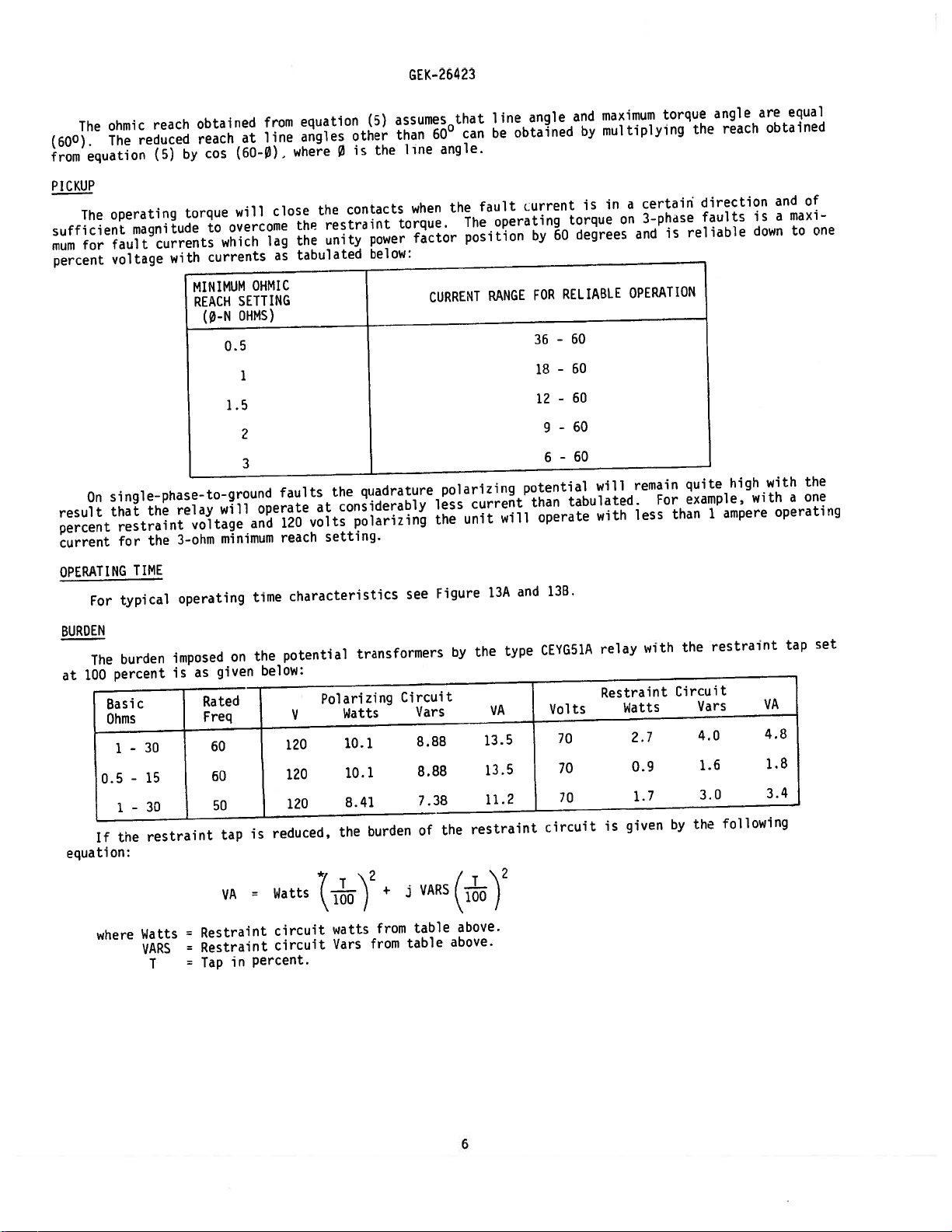
PICKUP
The
sufficient
for
mum
percent
single-phase-to-ground
On
result
percent
current
OPERATING
For
BURDEN
The
100
at
Basic
Ohms
0.5
If
equation:
operating
magnitude
fault
voltage
the
that
restraint
the
for
TIME
typical
burden
percent
30
-
1
15
-
30
-
1
restraint
the
torque
currents
with
relay
3-ohm
operating
imposed
is
will
overcome
to
which
currents
MINIMUM
SETTING
REACH
OHMS)
(0-N
0.5
1
1.5
2
will
voltage
minimum
on
given
as
Rated
Freq
60
60
50
tap
VA
close
lag
as
OHMIC
faults
operate
120
and
reach
time
potential
the
below:
reduced,
is
Watts
contacts
the
restraint
the
unity
the
tabulated
the
considerably
at
volts
setting.
characteristics
Polarizing
V
120
120
120
Watts
10.1
10.1
8.41
the
*()2
torque.
power
below:
quadrature
polarizing
see
transformers
Circuit
burden
+
,j
the
when
factor
CURRENT
polarizing
less
the
Figure
by
Vars
8.88
8.88
7.38
the
of
VARS(.j-)
fault
operating
The
position
RANGE
current
unit
13A
the
VA
13.5
13.5
11.2
restraint
will
type
urrent
by
FOR
36
18-60
1?
9
6
potential
than
operate
and
CEYG51A
circuit
is
torque
degrees
60
RELIABLE
60
-
60
-
60
-
60
-
tabulated.
13B.
Volts
70
70
70
a
in
on
OPERATION
will
with
relay
Restraint
Watts
given
is
certain
3-phase
and
remain
less
with
2.7
0.9
1.7
is
For
reliable
quite
example,
than
the
Circuit
the
by
direction
faults
high
ampere
1
restraint
Vars
4,0
1.6
3.0
following
is
down
with
with
VA
4.8
1.8
3.4
of
and
maxi
a
one
to
the
one
a
operating
set
tap
where
Watts
VARS
T
Restraint
=
Restraint
=
Tap
=
in
circuit
circuit
percent.
watts
Vars
from
from
table
table
above.
above.
6

The
burdens
Basic
Ohms
-
0.5
-
-
1
NOTE:
imposed
30
15
30
Above
for
the
Rated
Freq.
60
60
50
data
lower
on
GEK-26423
the
current
I
5
5
5
For
is
reach
3-4,
the
5-6,
0.070
0.007
0.058
mho
tap
transformers
7-8
or
R
units
settings
X
0.040
0.005
0.033
set
will
by
Circuit
on
be
the
their
0.080
0.008
0.067
less
current
Z
maximum
than
circuits
I
5
5
5
ohmic
the
9-10
P
0.210
0.021
0.175
reach
tabulated
are
given
Circuit
0.120
0.013
0.100
taps.
burdens.
below:
X
The
Z
0.240
0.024
0.200
burden
quently
be
followed
1.
2.
The
Consider
Assume
in
applying
do
not
to
Determine
the
necessary
line
Determine
relay
When
a.
further
When
b.
no
c.
If
determine
lay,
following
the
Z
1
the
materialize.
determine
power
if
terminal.
zero
zero
further
neither
Type
calculations
the
protected
following
=
=
relay
if
zero
rnho
loadings
there
sequence
evaluation
sequence
if
CFPH16A.
24.0
72.0
to
a
Therefore,
final
what
sequence
unit
and
is
a
evaluation
nor
a
b
is
it
line
characteristics:
/790
primary
/750
primary
particular
calculations
current
tap
settings
power
limitation
current
need
be
current
need
above
necessary
are
made
to
be
CALCULATION
line
it
is
compensation
and
swings.
in
compensation
made.
compensation
be
made.
applicable,
is
to
use
as
an
between
ohms
ohms
OF
and
system,
reconinended
may
be
the
relation
Appendix
See
application
the
is
Appendix
See
is
Appendix
See
evaluate
the
zero
example
of
breakers
SETTINGS
the
that
necessary
is
required.
I,
used:
iQi
II,
used:
sequence
determining
and
A
limitations
the
the
of
equations
for
equations
(3K
if
III,
equations
the
on
B
initial
and
how
This
resulting
incorrect
if
Coisequal
+
1)
equations
directional
the
portion
the
outlined
calculations
the
relay
will
mho
and
1b
operation
Ha,
lIb
Co
is
lila,
of
either
overcurrent
actual
of
under
maybeapplied.
depend
characteristic
I.
or
to
and
equal
Ilib
Appendix
tap
settings
system
a
APPLICATION
of
1
upon
on
faults
on
than
less
lIc.
or
less
to
and
IlIc.
supervising
showninFig.
and
2
evaluation
with
behind
C,
than
II
or
to
be
below
no
III
used.
fre
of
the
the
C,
to
re
5.
Checking
breaker
Z
CT
Ratio
PT
Ratio
Secondary
=
=
=
Zom
Appendix
detect
A
to
2.4
7.2
1.4
=
Ohms
/79°
/750
/75°
a
14.4
600/5
1200/1
=
I
single
L°
=
=
=
first
CT
PT
Ratio
Ratio
0.47
1.9
0.36
phase
primary
+
+
+
to
establish
x
j2.36
j5.95
jl.35
to
ohms
Primary
secondary
secondary
secondary
ground
Ohms
the
fault
ohms
ohms
ohms
maximum
(F2)
7
tap
at
setting
the
remote
that
bus,
would
still
Equation
permit
should
Tb
the
CEYGSIA
used.
be
at
GEK-26423
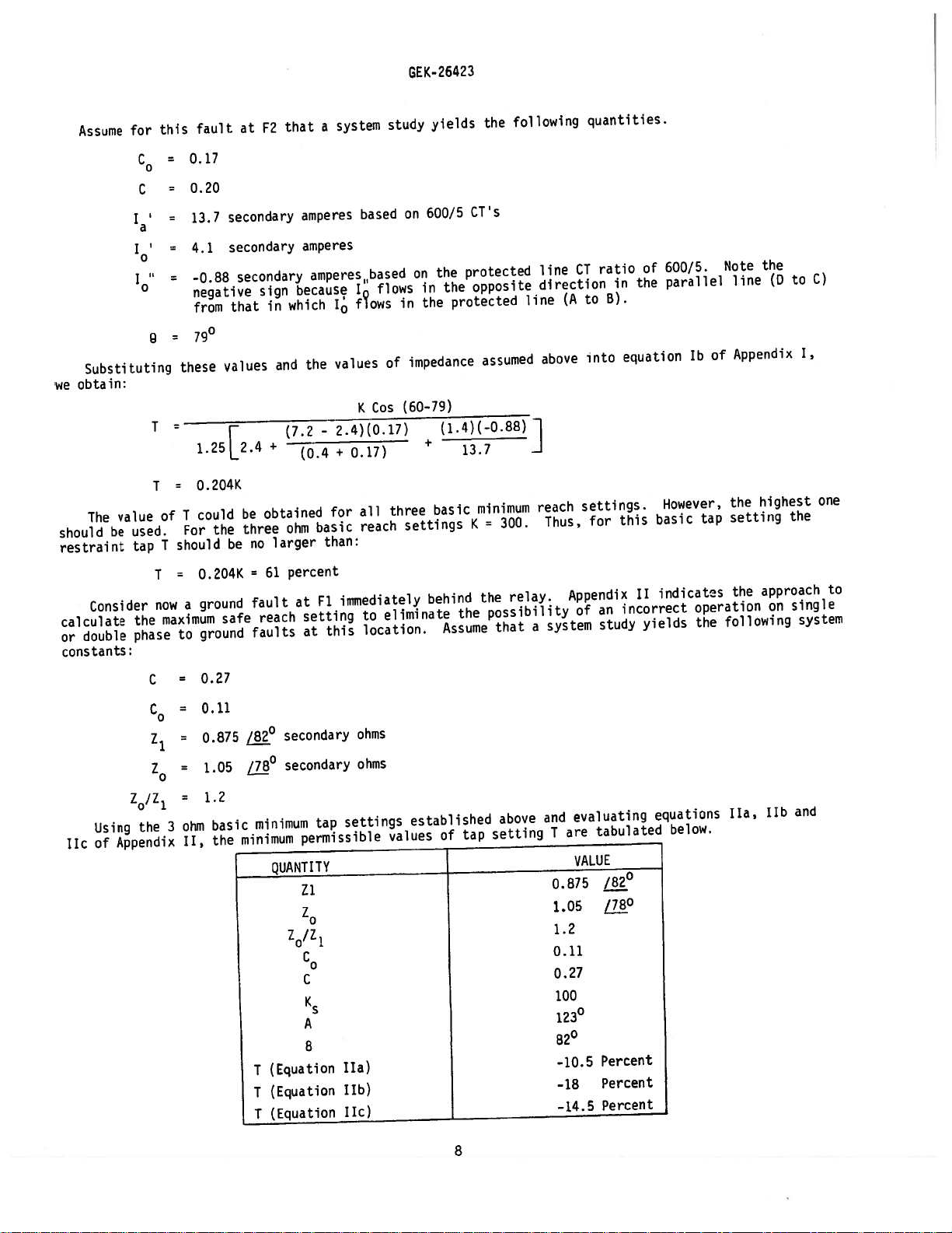
Assume
Substituting
obtain:
we
The
should
restraint
Consider
calculate
double
or
constants:
value
be
for
C
0
C
‘a’
10
used.
tap
the
phase
this
=
=
=
0
these
T
T
I
of
I
should
=
I
now
maximum
to
fault
0.17
0.20
13.7
4.1
-0.88
negative
from
790
‘25L
24
0.204K
could
For
0.204K
ground
a
ground
at
secondary
secondary
secondary
that
values
r
be
three
the
be
safe
F2
sign
in
+
obtained
no
61
=
fault
reach
faults
that
amperes
amperes
because
which
and
(7.2
(0.4
ohm
larger
percent
at
system
a
based
amperesbased
I
J
flows
values
the
K
-2.4)(0.17)
0.27)
+
all
for
reach
basic
than:
immediately
Fl
setting
this
at
study
flows
of
Cos
three
eliminate
to
location.
yields
600/5
on
the
on
in
the
in
impedance
(60—79)
(1.4)(-0.88)
+
basic
settings
behind
Assume
CT’s
protected
opposite
the
protected
13.7
K
the
following
the
assumed
minimum
300.
=
relay.
the
possibility
that
line
direction
line
above
reach
Thus,
system
a
quantities.
ratio
CT
to
(A
into
settings.
for
Appendix
an
of
study
in
8).
equation
this
incorrect
of
the
II
yields
600/5.
parallel
lb
However,
basic
indicatos
Note
line
Appendix
of
the
setting
tap
the
operation
following
the
the
to
(D
highest
the
approach
single
on
C)
1,
one
to
system
TIc
Using
Appendix
of
C
C
0
Z
1
ZQ/Z
1
the
0.27
0.11
=
ohms
ohms
/780
secondary
secondary
0.875
Z
0
1.05
1.2
evaluating
arid
settings
3
II,
the
minimum
minimum
basic
ohm
tap
permissible
established
values
of
QUANTITY
Zi
Z
0
Z0/Z
1
C
0
C
tap
above
setting
are
T
0.875
1.05
1.2
0.11
0.27
tabulated
VALUE
/820
LL8_°
equations
below.
ha,
and
JIb
100
123
82°
-10.5
-18
-14.5
Percent
Percent
Percent
(Equation
T
(Equation
T
(Equation
T
A
8
ha)
lib)
Tic)
8

GEK-2
64
23
Since
the
tap
Since
setting
remote
These
If
the
tings
be
at
the
carrier
terminal
be
set
In
setting.
reach
If
Thus,
all
setting
the
should
terminal.
same
application
of
the
least
and
sensitively
as
any
case,
Thus,
setting
zero
obtain.
we
the
for
percent
61
be
calculations
carrier
1.25
times
starting
they
ALWAYS
the
the
as
sequence
values
this
used.
Thus,
is
starting
relay
will,
carrier
tripping
current
of
application.
setting
It
for
T
Set
for
directional
the
therefore,
possible.
as
set
K
Tinthe
will
desirable
is
50
percent
61
=
-
tap
on
should
CEYG51A
setting
at
the
the
relays
start
CEYG51A
compensation
6.95
=
above
Thus,
insure
additional
41
percent
percent
40
repeated
be
comparison
relays
of
the
terminal
rear
coordinate
that
CEYG51A
relay
-
2.36
3(2.36)
table
to
set
tripping
must
relay
at
is
are
relays
the
that
the
for
carrier,
at
both
will
properly.
coordinate
at
terminal
used,
4.59
=
7.08
negative,
the
relay
reach
the
terminals.
relay
outreach
terminal
equation
maybeset
relay
to
the
relays
it
at
In
A.
0.65
=
these
will
reach
restraint
at
will
remote
the
the
any
event
with
should
B
should
Ic
per
in
reach
at
the
also
The
carrier
each
unit
equations
the range
only
least
setting
tap
remote
be
necessary
carrier
terminal.
tripping
carrier
the
other
be
set
be
used
to
25
end
start
on
with
impose
of
the
to
50
should
of
This
the
the
instead
no
10to61
remote
percent
the
line
determine
to
relay
will
relay
starting
same
same
of
restrictions
percent.
bus,
beyond
be:
at
settings
insure
at
the
units
minimum
basic
basic
equation
a
lower
terminal
the
should
that
remote
should
minimum
lb.
on
the
B.
set
tap
For
maximum
the
The
associated
restraint
tion
details
The
cradle
the
case block
plug
can
attaches
vent
the
Outline
These
protect
transit.
the
transportation
ground
the
safe
Type
CEYG51A
tapped
circuits
of
components
is
locked
be
inserted
the
to
cover
and
relays,
against
them
If injury
fault
reach
relay
autotransformer
for
the
relay.
are
the
in
cradle
and
in
from
case
being
from
drilling
panel
when
damage.
or
company
=
T
immediately
F2
setting
consists
adjustment
Internal
mounted
case
by
block
place
the
replaced
included
not
damage
and
0.33K
when
using
of
for
of
angle
connections
a
cradle
on
means
completed
are
of
the
front
connection
and
until
dimensions
RECEIVING,
as
Iriniediately
resulting
promptly
0.33
=
x
behind the
zero
three
mho—type,
controlling
and
assembly
latches
of
includes
the connection
are
part
a
upon
from
rough
notify
relay,
percent
use
current
300=99
sequence
CONSTRUCTION
4—pole
reach
basic
of
at
through
plig
the
and
minimum
the
relay
which
the
top
removable
a
to
permit
target
can
plug
in
shown
HANDLING
of
receipt
a
Figure
AND
control
ofarelay,
handling
the
nearest
the
compensation.
induction
adjustable
ohmic
are
be
bottom.
and
testing
reset
has
15.
STORAGE
panel,
evident,
is
General
equation
resistors
reach.
shown
easily
connection
the
mechanism
inserted.
been
will
be
examine
Electric
of
cylinder
Figures
in
Figure
removed
electrical
The
plug.
relay
and
shipped
it
file
a
Apparatus
Appendix
units.
in
1
3.
from
in
interlock
an
in
any
for
damage
the
and
the
A
separate
its
cartons
damage
claim
Sales
III
calculate
to
Each
unit
polarizing
2
show
relay
case.
connections
testing
case.
The
arm
designed
sustained
at
once
Office.
has
and
construc
between
cover
to
pre
with
an
The
to
in
Reasonable
immediately,
and
metallic
cover
is
they
chips.
removed
care
should
and
should
Foreign
cause
be
be
exercised
stored
matter
trouble
in
their
collected
in
the
unpacking
in
original
operation
on
the
the
cartons
outside
of
9
the
relay.
relay.
from
way
to
be
moisture,
inside
when
dust,
the
are
the
place
case
relays
that
may
If
in
a
of
the
is
find
not
free
its
installed
GEK—26423
Immediately
damage
no
ViSUAL
INSPECTION
Check
received
agree
Remove
molded
parts
NECHANICAL
is
It
There
1.
tact
2.
lower
shaft
3.
.012
4.
that
5.
assembly
contacts
There
The
inch
The
The
closed
The
the
to
so
6.
should
There
armature
the
should
There
that
check
7.
connection
blocks,
gram.
Note
high
the
Figure
that
enough
main
improper
circuited.
upon
been
has
nameplate
the
with
relay
the
other
or
INSPECTION
recoimnended
should
should
should
screw
jewel
locked
contact
clearance
spring
just
it
clutch
at
armature
The
be
by
be
target
the
the
Check
diagram
that
and
11
there
so
brush.
adjustment
receipt
sustained
the
its
by
gap
windup
touches
of
the
screw
a
hand
least
at
location
for
the
shows
is
that
This
stamping
requisition.
from
signs
that
rio
be
be
an
be
bearing
between
each
moving
and
and
resets
long
auxiliary
an
when
is
of
its
of
the
noticeable
closed
end
set
each
on
should
the
contacts
in
check
1/32’
the
and
sectional
a
the
especially
the
the
of
shipment
in
case
physical
following
play
of
screw.
the
solid
unit
contact.
only
positively
the
of
relay.
short
connecting
auxiliary
to
when
each
unit
be
should
one
that
wipe
brush
relay
insure
check
and
friction
the
from
of
unit
should
stationary
sufficient
stop
the
of
of
the
on
contact
Be
brushes
view
important
brush
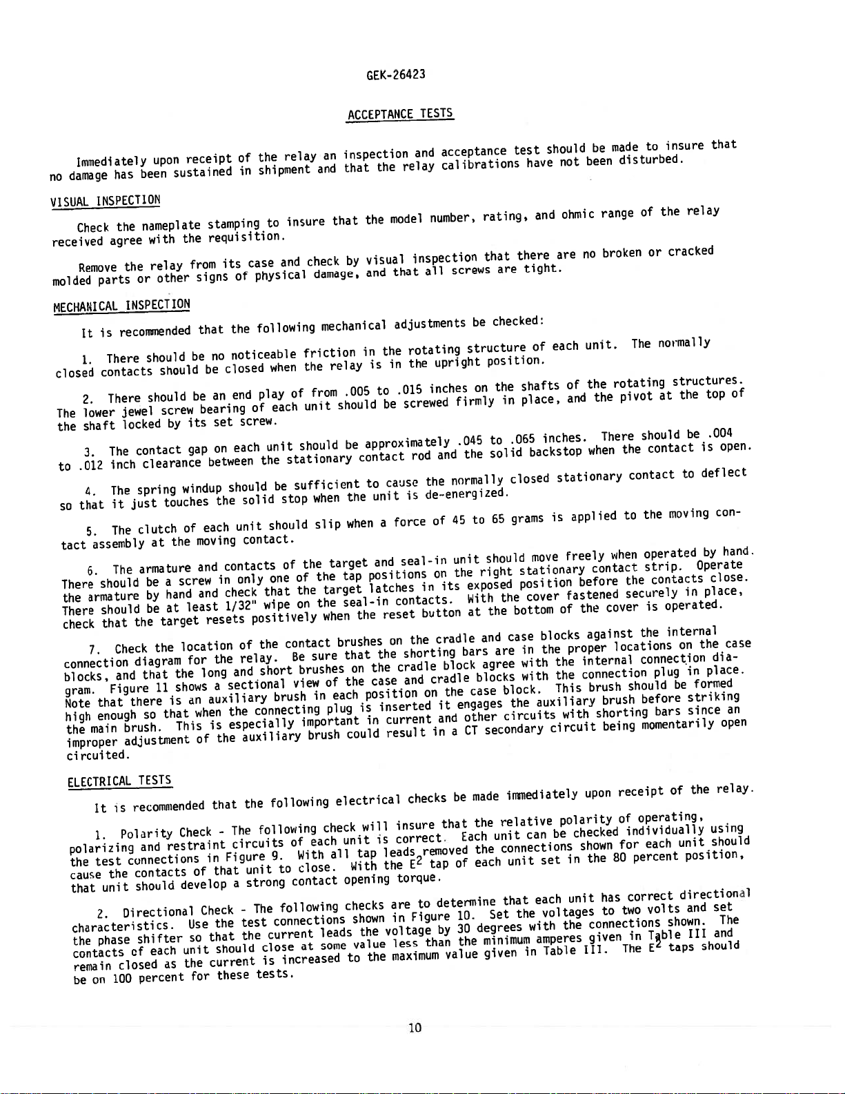
ACCEPTANCE
inspection
an
that
and
that
by
damage,
mechanical
relay
.005
should
be
tue
when
when
slip
target
tap
the
target
seal—in
the
when
brushes
that
sure
the
of
each
in
plug
could
the
model
the
visual
that
and
adjustments
the
in
in
is
to
be
approximately
contact
cause
to
unit
force
a
and
positions
latches
reset
the
on
the
the
on
case
position
inserted
is
current
in
result
TESTS
and
relay
inspection
all
rotating
the
.015
screwed
rod
the
de—energized.
is
seal-in
in
contacts.
button
the
shorting
cradle
and
on
acceptance
calibrations
number,
screws
upright
inches
firmly
.045
and
normally
45
of
unit
the
on
its
cradle
bars
block
cradle
the
engages
it
and
a
in
rating,
that
be
structure
pnsition.
on
the
to
should
right
exposed
With
the
at
and
agree
blocks
case
other
secondary
CT
test
there
are
checked:
the
in
.065
to
solid
closed
grams
65
the
bottom
case
are
block.
the
circuits
should
have
and
tight.
each
of
shafts
place,
inches.
backstop
is
move
stationary
position
cover
blocks
the
in
the
with
with
auxiliary
circuit
been
not
ohmic
no
are
unit.
the
of
and
when
stationary
applied
freely
before
fastened
the
of
against
proper
internal
connection
the
brush
This
with
made
be
range
broken
rotating
the
There
when
contact
cover
locations
brush
shorting
being
to
disturbed.
of
or
The
pivot
should
contact
the
contact
the
to
operated
strip.
contacts
the
securely
is
the
connection
plug
should
before
bars
momentarily
insure
relay
the
cracked
normally
structures.
the
at
be
to
moving
in
operated.
internal
on
in
be
striking
since
that
top
.004
is
deflect
con
by
Operate
close.
place,
the
dia
place.
formed
of
open.
hand.
case
an
open
ELECTRICAL
is
It
Polarity
1.
polarizina
connections
test
the
the
cause
unit
that
Directional
2.
characteristics.
phase
the
contacts
on
closed
100
remain
be
TESTS
recommended
Check
restraint
and
contacts
should
develop
shifter
of
the
dS
unit
each
percent
of
Use
so
for
that
-
in
that
Check
the
that
should
current
these
the
The
circuits
Figure
unit
a
-
test
the
following
strong
The
current
close
is
tests.
following
each
of
With
9.
close.
to
contact
following
connections
at
increased
electrical
check
all
leads
some
will
unit
tap
With
opening
checks
shown
the
value
the
to
insure
correct.
is
leads
the
torque.
are
in
voltage
less
maximum
checks
removed
E
2
to
Figure
than
10
be
that
of
tap
detennine
10.
30
by
the
value
made
Each
relative
the
unit
connections
the
each
Set
degrees
minimum
given
immediately
can
set
unit
each
that
voltages
the
with
amperes
Table
in
polarity
checked
be
in
unit
the
receipt
upon
of
shown
80
the
has
to
connections
given
III.
operating,
individually
each
for
percent
correct
volts
two
Tble
in
EL
The
the
of
unit
position,
directional
and
shown.
III
taps
relay.
using
shoulo
set
The
and
should

GEK-26423
Set
should
unit
3.
connections
amperes,
for
5
With
the
unit
of
contact
bisector
the
at
unit
the
phase
the
remain
Maximum
shown
phase
the
will
just
to
contact
left
Torque
with
be
open.
of
OHMIC
TAP
shifter
open
Figure
in
polarizing
shifter
closed.
the
just
REACH
SETTING
0.5
1.0
1.5
2.0
3.0
so
from
Angle
10,
set
These
angle
opens
(110
that
zero
The
-
but
voltage
so
Next
are
the
between
at
+
310)
current
the
to
60
maximum
with
at
operating
that
the
find
zero
the
110°
=
amperes.
torque
E
the
120
angles
torque
zero
two
3100.
and
210°,
TABLE
leads
tap
volts.
ie
MINIMUM
AMPERES
32
16
12
8
6
the
angle
disconnected.
current
either
on
angles
torque
The
300
lead
III
voltage
of
leads
of
lines.
angle
the
side
the
by
mho-type
The
polarizing
of
unit.
For
maximum
of
210
the
The
example,
degrees.
units
operating
voltage
3Q0
position
maximum
torque
MAXIMUM
AMPERES
60
60
60
60
60
The
contacts
be
can
checked
current
3Q0,
by
which
torque
will
that
be:
assume
using
should
the
cause
position
for
each
of
be
left
the
particular
a
the
set
contact
will
left
be
The
maximum
operating
Pickup
4.
+14
percent
at
with
Table
phase
5.
100
by
Compensating
set
and
voltage
in
the
compensating
but
connect
With
the
close
current
of
percent
the
30
IV.
angle
UNIT
0-N
0.5
1.0
1.5
2.0
3.0
windings
the
voltage,
left
torque
Check
the
relay
degrees,
Resistor
of
current
contact
angle
leads
-
The
minimum
the
and
connected
check
R11-R12-R
13
restraint
the
REACH
LINK
SETTING
Winding
between
UNIT
Ml
M2
M3
tap,
E
2
of
the
following
reach
voltage
0.5
1.0
1.5
2.0
3.0
circuits
and
each
the
of
polarizing
as
shown
as
that
circuit
Check
terminals
as
phase
unit.
units
voltage
check
given
adjusted
in
current
the
should
RESTRAINT
APPLIED
VOLTAGE
-
The
tabulated
Ii
STUD
angle
The
should
is
on
for
Figure
not
the
20V
25
35
35
70
following
9-10,
TO
3
5
7
set
current
for
to
the
the
10.
required
be
same
TABLE
is
in
as
30°
be
at
particular
a
determine
nameplate.
value
Set
to
used
to
the
as
IV
check
correct.
the
following:
the
in
should
lead,
that
These
shown
the
phase
close
adjust
angle
phase
POLAR.
APPLIED
VOLTAGE
1?OV
120
120
120
120
confirm
is
to
the
Use
12
STUD
10
10
10
be
check
one
pickup
±3°.
unit.
ohmic
the
checks
in
Table
shifter
the
contacts
pickup.
basic
TO
half
This
reach
should
IV
so
The
the
of
PICKUP
CURRENT
34.4
21.6
20.0
15.0
20.0
that
test
—
—
measure
(4),
the values
is
the
of
be
the
for
that
falls
resistors
polarizing
-
45.6
-
28.5
—
26.6
20.0
-
26.6
-
relative
the
connections
listed
angle
each
made
specific
current
within
JUMPER
STUDS
4-9
6-9
8-9
the
by
unit
with
are
circuit.
polarity
current
in
which
leads
the
used
PHASE
ANGLE
°LEAD
of
Table
witifl
is
the
ohmic
range
to
30°
300
300
300
300
Figure
required
1V.
the
E
range
make
of
taps
shown
the
10,
to
11
 Loading...