

GE 10266 GE Owner's Manual
Installation Instructions
Ribbed Side
Fig. 5
Smooth Side
Fig. 6
WARNINGS TO REDUCE THE RISK OF FIRE, ELECTRIC SHOCK
OR INJURY TO PERSONS:
WARNING
Risk of electric shock
-Use only insulated staples or plastic to secure the
cords
-Route and secure the cords so that they will not
be pinched or damaged
Risk of fire
-Keep away from materials that may burn
-Use only with a 12V, 10 watt Xenon bulb
-Not intended for installation in plastic cabinets
-Keep cord or combustibles such as plastic, paper
goods, and the like away from glass lens and
lamp. 12 in. minimum clearance recommended
-Position cabinet light with respect to cabinet to
permit reading of the lamp replacement
markings during relamping. Mount lamp facing
down
-Not intended for illumination of aquariums
-Do not conceal power supply cord inside a wall,
ceiling, soffit, kitchen cabinet , or similar
permanent structure
-Do not run the power supply cord through holes
in walls, ceilings, or floors
-Route and secure the cords so that they will not
be pinched or damaged when cabinet is pushed
to the wall
-Do not use an extension cord. Use power strip
SAVE THESE INSTRUCTIONS IN A LOCATION CLOSE TO YOUR
CABINET SO YOU CAN REFER TO THEM AT A LATER TIME.
We recommend you read through these instructions entirely before starting your installation in
order to help you understand all the steps and options pertaining to your particular installation.
The low voltage portable xenon light may be installed inside or under a kitchen cabinet, or other
built-in furniture when: 1) The low voltage Class 2 power supply is located outside the cabinet and
is not concealed; and 2) The line voltage (120V) power supply cord is not concealed or run through
openings in the cabinet, walls, ceilings, or floors. This requirement does not apply to the wiring
between the cabinet light and the power unit.The National Electrical Code (NEC) does not permit
cords to be concealed where damage to insulation may go unnoticed. To prevent fire danger, do
not run cord behind walls, ceilings, soffits, or cabinets where it may be inaccessible for
examination. Cords should be visually examined periodically and immediately replaced when any
damage is noted
with integral overcurrent protection to supply
other electrical devices or accessories in cabinet
-Do not locate puck lights closer than 2” (5.1 cm)
from cabinet wall or in a compartment smaller
than 12“ by 12” by 12” - one cubic foot (30.5 cm
by 30.5 cm by 30.5 cm) for each light fixture.
Three light fixtures require a minmum of three
cubic feet (0.085 cubic meters) of enclosed
space. Temperatures on the mounting surface
can reach 180˚ F (82˚C)
Risk of personal injury
-Turn off/unplug and allow to cool before
replacing the bulb
-Bulb and glass lens gets HOT quickly
-Lighted lamp and lens are HOT
-Do not touch hot lens or enclosure
-Do not remain in light if skin feels warm
-Do not look directly at lighted bulb
-Do not touch the bulb at any time. Use a soft
cloth. Oil from skin may damage the bulb
-Do not operate the unit with a missing or
damaged glass lens or UV filter
-Do not attempt to relocate any of the lights from
the installed location to a new location
-Do not install on walls or vertical surfaces
IMPORTANT SAFETY INSTRUCTIONS
This portable lamp has a polarized plug (one blade is wider than the other) as a feature to reduce
the risk of electric shock. This plug will fit in a polarized outlet only one way. If the plug does not fit
fully in the outlet, reverse the plug. If it still does not fit , contact a qualified electrician. Never use
with an extension cord. Do not alter the plug. Read entire installation procedure before you begin.
Mounting Preparation Instructions
3
Proceed to either Surface Mounting Installation or Recessed Mounting Installation based
4
on your desired method of installation.
Determine the location where you want the xenon light(s) to be
mounted, making sure the transformer wiring and housing will
reach the nearest outlet. Using a pencil or awl mark the
locations of the screw holes by holding the light head against
the mounting surface as shown (Fig. 3). Pre-drill holes in the
mounting surface with a 1/16” (1.6mm) drill bit.
You can trace the line voltage (120V) cord along the bottom
surface of the cabinet. Do NOT attempt to conceal the 120V
Fig. 3
power supply cord inside your cabinets.
Surface Mounting Installation
Please refer to the MOUNTING PREPARATION INSTRUCTION section for the first three (3) steps for
surface mount installation. This section only explains the mounting of the light fixtures, not
supplying the power to them.
1
OR
You can trace the low voltage (12V) cord along the bottom
surface of the cabinet or inside the cabinet (Fig. 1). To trace
your low voltage cord inside your cabinets, you must drill an
additional 1/4 in (6.35 mm), hole as shown in the illustration.
Do NOT attempt to conceal your transformer or the 120V
power supply cord inside your cabinets.
Fig. 1
Skirt
2
3
Mount remaining heads following Steps 1-3. Attach the re-lamping label (included in your
4
hardware kit) next to one of the heads for future reference when replacing.
While feeding both wires attached to the reflector cup
Fig. 2
through the housing, hold the reflector cup over the
pre-drilled holes you made earlier in the instructions (Fig. 2).
Using three (3) of the #2 x 1 in. screws (included), secure the
light reflector cup body to the mounting surface as shown.
Route the wires under the notched area of the housing.
NOTE: Make sure your wires are exiting on the side you want
them to. DO NOT install without skirt in place.
Re-attach the lens bezel to the light head by aligning the
Fig. 3
three (3) attachment legs in the cover with the
corresponding openings in the head (Fig. 3). Turn the lens
clockwise to lock it in place. Do NOT operate the xenon
lights without the lens bezels in place.
Recessed Mounting Installation
Your xenon lights can be recessed mounted into portable cabinets. Recessed mounting into fixed
kitchen cabinets is NOT recommended. Refer to the MOUNTING PREPARATION INSTRUCTIONS
section for the first three (3) steps for installation.
Mark the center point you wish the fixtures to be installed.
1
Fig. 1
Using a hole saw, drill a 2-1/8 in (5.40 cm). diameter hole
through the mounting surface (Fig. 1).
Mount remaining heads following Steps 1-3. Attach the re-lamping label (included in your
4
hardware kit) next to one of the heads for future reference when re-lamping.
Power Connections
DO NOT ATTEMPT TO TEST YOUR SYSTEM WITHOUT THE PLASTIC CONNECTOR PLUGS INSTALLED!
YOU CAN PERMANENTLY DAMAGE THE TRANSFORMER IF THE METAL TERMINALS ON LAMPS ARE
EXPOSED AND SHORTED. DOING SO WILL VOID YOUR WARRANTY.
Fig. 1
1
inside corners and edges for the neatest appearance, and to keep cords out of the way of
other items.
2
IMPORTANT: Once the connector plugs are attached, they
cannot be removed. If you plan to route the wires coming
from the heads through any additional cabinet walls or
surfaces, it is best to do the routing first, since routing holes
can be kept to a minimum size prior to attaching the
connectors. Install the plastic connector plugs over the
connection contacts on each head as shown (Fig. 1). For
routing of wires and power cords, we recommend following
Once the light heads are mounted to the cabinet surface, clip
the connectors together as shown (Fig. 2). To remove the
connector, depress the tab on the latching mechanism and pull
the connector away from the receptacle.
Fig. 2
First Light Connection
3
Line Transformer
4
3/4 in.
19 mm
Route the transformer power connectors to the individual
heads. If routing has to be done through adjoining cabinet
Fig. 3
walls, you will need to drill 3/4 in (1.91 cm). holes through
cabinet walls in order to route the power plugs to the individual
head locations (Fig. 3). Do NOT route the 120V power supply
cord through fixed cabinet walls.
After the power connector wires have been routed and in place,
Fig. 4
you can use the plastic nail-in wire guides to keep the wires
neatly in place and prevent them from sagging (Fig. 4).
Switch Installation
Transformer
Line Cord Switch
120V Power Cord
Fixtures being plugged into a switch controlled wall outlet will not require a line switch to be
installed. However, if the outlet is not switched, the line cord switch should be installed to switch
the light on and off. The line switch included in the hardware kit may differ from the one in the
illustrations, but it will be installed using the same basic instructions.
Choose a convenient, easy-to-reach location on the line cord
1
Fig. 1
to install the line cord switch. Mark the location on the smooth
side of the cord.
Low voltage transformer power connector cord
Put the other half of the switch body back on, and squeeze
the two halves together so the contact pins inside the switch
5
pierce the insulation on the cut wire (Fig 6). Replace the
attachment screw and nut, and tighten the switch body
back together.
Power Plug Instructions
If attached, slide the cover off the power plug as shown (Fig. 1). You can trim your 120V
1
supply cord to length to reduce excess cord length to your outlet.
Split the cord 1/8 in. from the end after you have adjusted the length to the outlet (Fig. 2).
2
Insert the blunt cut end of the power cord into the cavity on the inside end of the plug (Fig. 3).
Make sure that the ribbed side of the wire is in the position shown below.
Press the wire firmly into the plug and while holding the wire down, slide the cover back onto
3
the plug body (Fig. 4). Slide the cover completely over the plug so none of the wire inside the
plug is visible (Fig. 5). The cover will have a tight fit.
Fig. 2
Ribbed Side
Smooth Side
Ribbed Side
1/8 in.
3 mm
Fig. 1
Fig. 3
Fig. 4
Bulb Replacement Instructions
Relamp only with a 12V, 10W or less xenon bulb with G4 base.
Turn the light fixture off, and allow sufficient time for the
Fig. 1
Fig. 2
1
unit and bulb (lamp) to cool properly before handling.
Remove the lens cover from the Xenon heads by twisting
2
the lens cover counter-clockwise. Be careful not to drop
the lens, which can break.
Using a cloth or paper towel , grasp the bulb firmly and
3
pull bulb out of the socket. Re-insert a new bulb using a
paper towel or cloth to hold the bulb.
Rettach the lens cover to the head by aligning the three
4
(3) attachement legs in the cover with the corresponding
openings in the head. Turn the lens clockwise to lock it in
place. The lens cover is also the lamp and UV guard. Do
not operate the Xenon lights without the covers in place.
Fig. 3
Cleaning Instructions
Fig. 5
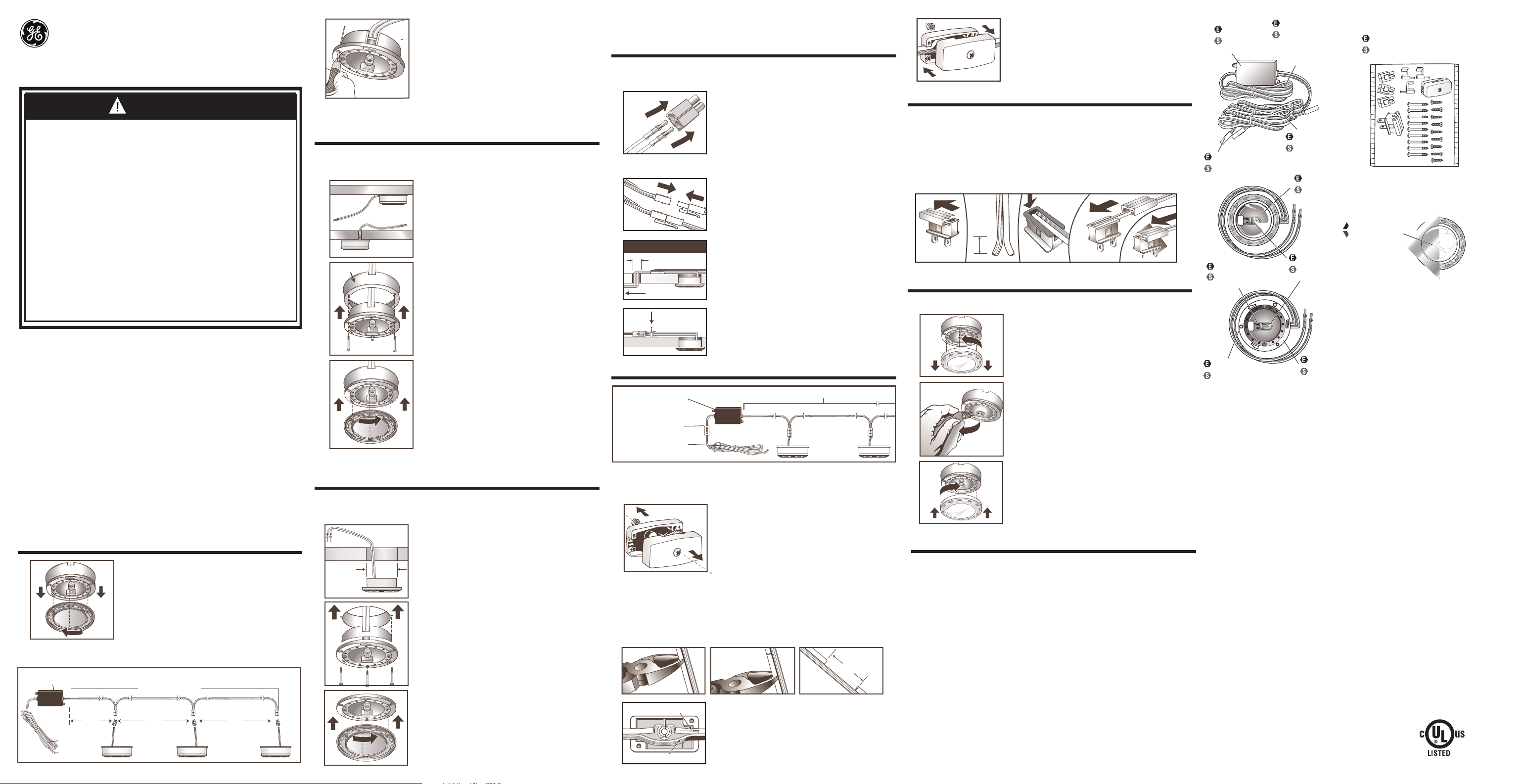
Transformer
Transformador
120V Line Cord
Cable de alimentación
(12 vatios)
3-Light Hardware Kit*
Juego de herrajería de 3 luces*
Low Voltage Cord
Cable de bajo voltaje
Connector Receptacle
de alimentación
Receptáculo de conector
Bezel/UV Filter
Chapa/Filtro UV
Bezel/UV Filter
Chapa/Filtro UV
Bulb
Reflector Cup
Bombilla
Copa del reflector
Mounting Hole
Agujero de montaje
Housing
Carcasa
*Actual hardware may differ from illustration.
*La tornillería puede variar de la que se muestra en la ilustración.
1
Remove the lens cover (bezel) from the xenon light by twisting
the bezel counter-clockwise (Fig. 1). Be careful not to drop the
lens, which can break.
Fig. 1
Determine the locations where you want the xenon light(s) to be mounted, making sure the
2
cords can reach the next subsequent Xenon light (Fig. 2).
Line Transformer
12 in.
30,5 cm
60 in. (1.52 m)
120V Power
Supply Cord
Minimum distance between lights
12V/Low Voltage Cord
12 in.
30,5 cm
12 in.
30,5 cm
Fig. 2
2
3
2-1/8 in.
5,4 cm
Fig. 3
Fig. 2
Using three (3) of the #2 x 1/2 in. screws, secure the head to
the mounting surface as shown (Fig. 2). Make sure you trace
the wires from the xenon light through the hole opening
prior to attaching the light to the mounting surface.
Re-attach the lens bezel to the light head by aligning the three
(3) attachment legs in the cover with the corresponding
openings in the head (Fig. 3). Turn the lens clockwise to lock it in
place. Do NOT operate the xenon lights without the lens bezels
in place.
Loosen the screw on the switch body, and separate the halves of the switch body. Make sure
2
not to lose the screw and small nut. (See Fig. 1)
In the area of the line cord where the switch is to be placed, cut a 5/8” (1.5 cm) slit in the
3
middle of the cord as shown (See Fig. 2, 3 and 4)
Cut through the smooth non-ribbed side of the line cord. CAUTION: DO NOT cut or damage
the insulation on the continuous side of the wire.
Fig. 2 Fig. 3
5/8 IN. (1.5 cm)
4
You will notice your line cord has one ribbed side and one
smooth side. The ribbed side is the neutral side of the wire.
Place the cord in the hollow half of the switch body as shown
(Fig 5). Make sure the cut sections of the wire do not touch
each other.
Fig. 4
Your fixture is made from quality materials that will last for many, many years with minimum
care. You may want to periodically clean the diffuser, or interior of the fixture using a mild,
non-abrasive glass cleaner and soft cloth. Do NOT use solvents, or cleaners containing abrasive
agents. When cleaning the inside of the fixture, make sure you have the power turned off, and do
not spray liquid cleaner directly onto the bulb, socket, transformer or wiring.
Xenon 3 Pack Puck Light
GE is a trademark of the
General Electric Company
and is used under license to
Jasco Products Company LLC,
10 E. Memorial Rd.,
Oklahoma City, OK 73114.
www.jascoproducts.com.
6/28/11
10266
 Loading...